EP3454080A1 - Single scatterer test using phase change - Google Patents
Single scatterer test using phase change Download PDFInfo
- Publication number
- EP3454080A1 EP3454080A1 EP17190579.7A EP17190579A EP3454080A1 EP 3454080 A1 EP3454080 A1 EP 3454080A1 EP 17190579 A EP17190579 A EP 17190579A EP 3454080 A1 EP3454080 A1 EP 3454080A1
- Authority
- EP
- European Patent Office
- Prior art keywords
- target object
- radar
- signal
- doppler
- bin
- Prior art date
- Legal status (The legal status is an assumption and is not a legal conclusion. Google has not performed a legal analysis and makes no representation as to the accuracy of the status listed.)
- Granted
Links
Images

Classifications
-
- G—PHYSICS
- G01—MEASURING; TESTING
- G01S—RADIO DIRECTION-FINDING; RADIO NAVIGATION; DETERMINING DISTANCE OR VELOCITY BY USE OF RADIO WAVES; LOCATING OR PRESENCE-DETECTING BY USE OF THE REFLECTION OR RERADIATION OF RADIO WAVES; ANALOGOUS ARRANGEMENTS USING OTHER WAVES
- G01S13/00—Systems using the reflection or reradiation of radio waves, e.g. radar systems; Analogous systems using reflection or reradiation of waves whose nature or wavelength is irrelevant or unspecified
- G01S13/006—Theoretical aspects
-
- G—PHYSICS
- G01—MEASURING; TESTING
- G01S—RADIO DIRECTION-FINDING; RADIO NAVIGATION; DETERMINING DISTANCE OR VELOCITY BY USE OF RADIO WAVES; LOCATING OR PRESENCE-DETECTING BY USE OF THE REFLECTION OR RERADIATION OF RADIO WAVES; ANALOGOUS ARRANGEMENTS USING OTHER WAVES
- G01S7/00—Details of systems according to groups G01S13/00, G01S15/00, G01S17/00
- G01S7/02—Details of systems according to groups G01S13/00, G01S15/00, G01S17/00 of systems according to group G01S13/00
- G01S7/41—Details of systems according to groups G01S13/00, G01S15/00, G01S17/00 of systems according to group G01S13/00 using analysis of echo signal for target characterisation; Target signature; Target cross-section
- G01S7/415—Identification of targets based on measurements of movement associated with the target
-
- G—PHYSICS
- G01—MEASURING; TESTING
- G01N—INVESTIGATING OR ANALYSING MATERIALS BY DETERMINING THEIR CHEMICAL OR PHYSICAL PROPERTIES
- G01N22/00—Investigating or analysing materials by the use of microwaves or radio waves, i.e. electromagnetic waves with a wavelength of one millimetre or more
-
- G—PHYSICS
- G01—MEASURING; TESTING
- G01S—RADIO DIRECTION-FINDING; RADIO NAVIGATION; DETERMINING DISTANCE OR VELOCITY BY USE OF RADIO WAVES; LOCATING OR PRESENCE-DETECTING BY USE OF THE REFLECTION OR RERADIATION OF RADIO WAVES; ANALOGOUS ARRANGEMENTS USING OTHER WAVES
- G01S13/00—Systems using the reflection or reradiation of radio waves, e.g. radar systems; Analogous systems using reflection or reradiation of waves whose nature or wavelength is irrelevant or unspecified
- G01S13/02—Systems using reflection of radio waves, e.g. primary radar systems; Analogous systems
- G01S13/06—Systems determining position data of a target
- G01S13/08—Systems for measuring distance only
-
- G—PHYSICS
- G01—MEASURING; TESTING
- G01S—RADIO DIRECTION-FINDING; RADIO NAVIGATION; DETERMINING DISTANCE OR VELOCITY BY USE OF RADIO WAVES; LOCATING OR PRESENCE-DETECTING BY USE OF THE REFLECTION OR RERADIATION OF RADIO WAVES; ANALOGOUS ARRANGEMENTS USING OTHER WAVES
- G01S13/00—Systems using the reflection or reradiation of radio waves, e.g. radar systems; Analogous systems using reflection or reradiation of waves whose nature or wavelength is irrelevant or unspecified
- G01S13/02—Systems using reflection of radio waves, e.g. primary radar systems; Analogous systems
- G01S13/06—Systems determining position data of a target
- G01S13/08—Systems for measuring distance only
- G01S13/10—Systems for measuring distance only using transmission of interrupted, pulse modulated waves
- G01S13/26—Systems for measuring distance only using transmission of interrupted, pulse modulated waves wherein the transmitted pulses use a frequency- or phase-modulated carrier wave
-
- G—PHYSICS
- G01—MEASURING; TESTING
- G01S—RADIO DIRECTION-FINDING; RADIO NAVIGATION; DETERMINING DISTANCE OR VELOCITY BY USE OF RADIO WAVES; LOCATING OR PRESENCE-DETECTING BY USE OF THE REFLECTION OR RERADIATION OF RADIO WAVES; ANALOGOUS ARRANGEMENTS USING OTHER WAVES
- G01S13/00—Systems using the reflection or reradiation of radio waves, e.g. radar systems; Analogous systems using reflection or reradiation of waves whose nature or wavelength is irrelevant or unspecified
- G01S13/02—Systems using reflection of radio waves, e.g. primary radar systems; Analogous systems
- G01S13/06—Systems determining position data of a target
- G01S13/42—Simultaneous measurement of distance and other co-ordinates
-
- G—PHYSICS
- G01—MEASURING; TESTING
- G01S—RADIO DIRECTION-FINDING; RADIO NAVIGATION; DETERMINING DISTANCE OR VELOCITY BY USE OF RADIO WAVES; LOCATING OR PRESENCE-DETECTING BY USE OF THE REFLECTION OR RERADIATION OF RADIO WAVES; ANALOGOUS ARRANGEMENTS USING OTHER WAVES
- G01S13/00—Systems using the reflection or reradiation of radio waves, e.g. radar systems; Analogous systems using reflection or reradiation of waves whose nature or wavelength is irrelevant or unspecified
- G01S13/88—Radar or analogous systems specially adapted for specific applications
- G01S13/93—Radar or analogous systems specially adapted for specific applications for anti-collision purposes
- G01S13/931—Radar or analogous systems specially adapted for specific applications for anti-collision purposes of land vehicles
-
- G—PHYSICS
- G01—MEASURING; TESTING
- G01N—INVESTIGATING OR ANALYSING MATERIALS BY DETERMINING THEIR CHEMICAL OR PHYSICAL PROPERTIES
- G01N2223/00—Investigating materials by wave or particle radiation
- G01N2223/05—Investigating materials by wave or particle radiation by diffraction, scatter or reflection
- G01N2223/052—Investigating materials by wave or particle radiation by diffraction, scatter or reflection reflection
-
- G—PHYSICS
- G01—MEASURING; TESTING
- G01S—RADIO DIRECTION-FINDING; RADIO NAVIGATION; DETERMINING DISTANCE OR VELOCITY BY USE OF RADIO WAVES; LOCATING OR PRESENCE-DETECTING BY USE OF THE REFLECTION OR RERADIATION OF RADIO WAVES; ANALOGOUS ARRANGEMENTS USING OTHER WAVES
- G01S13/00—Systems using the reflection or reradiation of radio waves, e.g. radar systems; Analogous systems using reflection or reradiation of waves whose nature or wavelength is irrelevant or unspecified
- G01S13/02—Systems using reflection of radio waves, e.g. primary radar systems; Analogous systems
- G01S13/50—Systems of measurement based on relative movement of target
- G01S13/58—Velocity or trajectory determination systems; Sense-of-movement determination systems
- G01S13/581—Velocity or trajectory determination systems; Sense-of-movement determination systems using transmission of interrupted pulse modulated waves and based upon the Doppler effect resulting from movement of targets
- G01S13/582—Velocity or trajectory determination systems; Sense-of-movement determination systems using transmission of interrupted pulse modulated waves and based upon the Doppler effect resulting from movement of targets adapted for simultaneous range and velocity measurements
-
- G—PHYSICS
- G01—MEASURING; TESTING
- G01S—RADIO DIRECTION-FINDING; RADIO NAVIGATION; DETERMINING DISTANCE OR VELOCITY BY USE OF RADIO WAVES; LOCATING OR PRESENCE-DETECTING BY USE OF THE REFLECTION OR RERADIATION OF RADIO WAVES; ANALOGOUS ARRANGEMENTS USING OTHER WAVES
- G01S13/00—Systems using the reflection or reradiation of radio waves, e.g. radar systems; Analogous systems using reflection or reradiation of waves whose nature or wavelength is irrelevant or unspecified
- G01S13/02—Systems using reflection of radio waves, e.g. primary radar systems; Analogous systems
- G01S13/50—Systems of measurement based on relative movement of target
- G01S13/58—Velocity or trajectory determination systems; Sense-of-movement determination systems
- G01S13/583—Velocity or trajectory determination systems; Sense-of-movement determination systems using transmission of continuous unmodulated waves, amplitude-, frequency-, or phase-modulated waves and based upon the Doppler effect resulting from movement of targets
- G01S13/584—Velocity or trajectory determination systems; Sense-of-movement determination systems using transmission of continuous unmodulated waves, amplitude-, frequency-, or phase-modulated waves and based upon the Doppler effect resulting from movement of targets adapted for simultaneous range and velocity measurements
-
- G—PHYSICS
- G01—MEASURING; TESTING
- G01S—RADIO DIRECTION-FINDING; RADIO NAVIGATION; DETERMINING DISTANCE OR VELOCITY BY USE OF RADIO WAVES; LOCATING OR PRESENCE-DETECTING BY USE OF THE REFLECTION OR RERADIATION OF RADIO WAVES; ANALOGOUS ARRANGEMENTS USING OTHER WAVES
- G01S13/00—Systems using the reflection or reradiation of radio waves, e.g. radar systems; Analogous systems using reflection or reradiation of waves whose nature or wavelength is irrelevant or unspecified
- G01S13/66—Radar-tracking systems; Analogous systems
- G01S13/72—Radar-tracking systems; Analogous systems for two-dimensional [2D] tracking, e.g. combination of angle and range tracking, track-while-scan radar
- G01S13/723—Radar-tracking systems; Analogous systems for two-dimensional [2D] tracking, e.g. combination of angle and range tracking, track-while-scan radar by using numerical data
- G01S13/726—Multiple target tracking
-
- G—PHYSICS
- G01—MEASURING; TESTING
- G01S—RADIO DIRECTION-FINDING; RADIO NAVIGATION; DETERMINING DISTANCE OR VELOCITY BY USE OF RADIO WAVES; LOCATING OR PRESENCE-DETECTING BY USE OF THE REFLECTION OR RERADIATION OF RADIO WAVES; ANALOGOUS ARRANGEMENTS USING OTHER WAVES
- G01S13/00—Systems using the reflection or reradiation of radio waves, e.g. radar systems; Analogous systems using reflection or reradiation of waves whose nature or wavelength is irrelevant or unspecified
- G01S13/02—Systems using reflection of radio waves, e.g. primary radar systems; Analogous systems
- G01S2013/0236—Special technical features
- G01S2013/0245—Radar with phased array antenna
-
- G—PHYSICS
- G01—MEASURING; TESTING
- G01S—RADIO DIRECTION-FINDING; RADIO NAVIGATION; DETERMINING DISTANCE OR VELOCITY BY USE OF RADIO WAVES; LOCATING OR PRESENCE-DETECTING BY USE OF THE REFLECTION OR RERADIATION OF RADIO WAVES; ANALOGOUS ARRANGEMENTS USING OTHER WAVES
- G01S7/00—Details of systems according to groups G01S13/00, G01S15/00, G01S17/00
- G01S7/02—Details of systems according to groups G01S13/00, G01S15/00, G01S17/00 of systems according to group G01S13/00
- G01S7/41—Details of systems according to groups G01S13/00, G01S15/00, G01S17/00 of systems according to group G01S13/00 using analysis of echo signal for target characterisation; Target signature; Target cross-section
- G01S7/414—Discriminating targets with respect to background clutter
Definitions
- This invention relates to a method of detection and subsequent characterization of objects using radar techniques and in particular determining whether an object is a single scatterer. It has application in determining a suitable landmark for geographical mapping for the purpose of determining the position of a host vehicle.
- Self-localization that is determining the precise location of a host vehicle is one of the most important functions for accurate automated driving or such driver assistance schemes such as collision prevention systems.
- Current car navigation systems generally use a GPS navigation system to estimate the vehicle position.
- GPS navigation system is insufficient for precise self-localization of road vehicles due to effects such as reflections caused by buildings and occlusions of GPS signals from satellites.
- many landmark-based ego localization approaches have been elaborated in the past.
- Such radar systems are able to detect radar reflections (i.e. radar detections) from objects in the vicinity and process the data with respect to said radar reflections.
- radar reflections i.e. radar detections
- the information needed for current self localization and mapping (SLAM) procedure is collected from such (reflection/detection) data provided by the radar modules over multiple consecutive scans to identify for example a fixed landmark.
- This mapping information is updated over time, and a precise superposition of the individual radar-based maps with the GPS maps is performed. In such a way, for example the geographical position determined by GPS is accurately refined by such local data from radar returns.
- landmark-based alignment of those radar images is a preferred solution.
- a key task is to determine one or more suitable landmarks (i.e. objects) in the environment, i.e. in the vicinity of the vehicle which could serve as suitable and quality positional references (anchors) for precise superposition of the individual maps.
- Determining whether an object is a single-scatterer can be helpful in determining whether a landmark is suitable so an aim is to determine the extent to which a scatterer under test (SUT) is a single scatterer (originates from a single scattering center).
- SUT scatterer under test
- pulse-Doppler radar signal processing can be used to separate reflected signals into a number of "peaks", which occur in the 2-D spectral domain (called range-Doppler map). This spectral data collected from multiple radar receiver channels is utilized to carry out the here proposed single scatterer test.
- the cross-correlation involves computational complexity. Aditionally, this method is not very sensitive.
- the current application relates to an improved method of determining whether a target object identified is a single scatterer.
- One object is to provide a method to determine the suitability of a landmark as a reference.
- the aim of the proposed method is to determine the extent to which a scatterer under test (SUT) is a single scatterer (originates from a single scattering center).
- SUT scatterer under test
- a vehicle based method of determining the extent to which a target object is a single scatterer said vehicle including a radar system including a radar transmit element, adapted to send a radar signal towards said target object, and an antenna receive element adapted to receive radars signals reflected from said target object, said method comprising :
- Step c) may comprise processing the data to provide phase data in relation to discrete bins comprising frequency ranges, and step d) comprises determining the phase difference between at least two bins.
- step c) signal data may be converted from the base time-domain to a range-Doppler frequency domain.
- Step c) may include providing a range-Doppler map in terms of range-Doppler frequency domain.
- Step c) may include providing phase data in term of (range-Doppler) frequency bins.
- Step d) may comprise determining bin-to-bin phase change.
- step e) if the phase change between two frequencies or frequency bins is above a threshold, the target object is considered to be a non-single scatterer.
- the target may be considered to be a non-single scatterer.
- Steps d) and e) may only performed the bins from the main-lobe (1-D or 2-D) region of the received radar point spread function.
- step c) only phase information from the (2-D) measured data in the range-Doppler domain is extracted for frequencies or bins where the amplitude or power exceeds a threshold or which have a minimum signal-to-noise ratio.
- Step d) may comprise measuring bin-to-bin phase change across the measured 2-D point spread function evaluated in the range-Doppler domain.
- the aim of the proposed method is to determine the extent to which a scatterer under test (SUT) is a single scatterer (originates from a single scattering center).
- SUT scatterer under test
- pulse-Doppler radar signal processing can be used to separate reflected signals into a number of "peaks", which occur in the 2-D spectral domain (called range-Doppler map). This spectral data is utilized to carry out the here proposed single scatterer test.
- the 2-D frequency-domain data (the range-Doppler map) is analysed.
- the data is arranged in terms of a set of frequency ranges or "bins".
- bins As it is a matter of interference between signals reflected from scattering centers located in relative close proximity to each other (in terms of range/Doppler frequencies), relative phase difference between signals can be directly evaluated in the frequency domain local to the superposed signal frequency bin.
- phase information from the (2-D) measured complex data is extracted at the position of the peak (considering only those bins where the amplitude exceeds some threshold or having a minimum SNR, respectively). Then, the bin-to-bin phase change across the (whole) measured 2-D PSF (corresponding to a detected target) is evaluated in the range-Doppler domain.
- the amount of the neighboring bins is not limited. Even having only two neighboring bins (offering the needed SNR), the test can be executed.
- the method is preferably executed on the bins from the main-lobe 2-D region of the PSF (also called "peak").
- the method may be reduced (for a better runtime performance) to the phase analysis of only the vectors in the two orthogonal dimensions (range and Doppler) going through the estimated amplitude peak position (as a function of range/Doppler frequency). This provides a sub-set of bins compared to the analysis of all bins of a 2-D PSF.
- the target is considered to be a non-single scatterer.
- phase of all bins belonging to the main lobe of an ideal single scatterer PSF would be namely equal/"flat" when the windowing function is symmetrical, the number of samples (processed by e.g. a Fourier transform) is odd, and (if zero padding is needed) the so-called zero-phase zero padding approach is applied.
- This methodology is applicable to a system which includes a single receiver channel (receiver element), but also on M range-Doppler responses (maps) from N receiver (RX) channels.
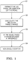
- Figure 1 shows a flow chart of the general methodology according to one aspect
- a (vehicle-based) radar system comprising an antenna transmit element and a receive element (or array) having at least one receive element sends out a radar signal and so the received reflected signal from a target object is received by the receiver element(s) and processed.
- the subsequent processing of the received radar signal i.e. analysis is described with reference to flowchart of figure 1 .
- 2-D frequency-domain data (a range-Doppler map) is analyzed.
- step S1 the phase of the signal is extracted from the 2-D frequency domain data at the position of the amplitude peak.
- the data is arranged in terms of a set of frequency ranges - so called Doppler "bins".
- Doppler "bins" As it is a matter of interference between signals reflected from scattering centers located in relative close proximity to each other in space (and/or having similar Doppler frequency), amplitude spectral information from the (2-D) measured complex data (in the range-Doppler domain) are evaluated at the position of the resulting "peak" to determine if the measured response originates from a single scattering center or not.
- step S2 the frequency (bin) to frequency (bin) phase is determined.
- step S3 the phase change from one frequency (bin) to a neighboring one frequency (bin) is compared with a threshold. If this phase difference (after phase unwrapping) exceeds the threshold in step S4, the target is identified as a non-single scatterer.
- Target 1 and 2 Two scattering centers
- PSF1 and PSF2 a non-single scatterer
- PSF 1,A and PSF 2 A may be close to each other and would overlap - see figure 2 .
- the amplitudes and the phases of the complex-valued PSFs have a strong influence on the resulting PSF due to complex superposition of the individual PSFs (see figure 2 ).
- the peak amplitude is shown at frequency fR1, A and fR2,A respectively for the PSF1,A and PSF 2, A.
- a 1-D case was simulated where two PSFs with a frequency distance of 1.0 frequency bin were put in a close proximity to each other.
- the first PSF (PSF1) has amplitude of 1.0 and phase of 0 degrees
- the second one (PSF2) has amplitude of 0.9 and phase of 30 degrees.
- Figure 3 shows the results of phase determined against frequency bin for the first PSF only (reference numeral 1) the second PSF only (reference numeral 2) and for the actual superposed signal (which is the signal that would be received in reality): reference numeral 3.
- phase vs. frequency bins shown as a 1-D cut through a 2-D frequency map.
- the phase of the superposed resulting peak is not flat.
- the peak under tests is determined to originate from a non-single scatterer.
- the method is very sensitive, can be executed on a single range-Doppler map (originating from a single RX channel), and has a low computational cost.
Landscapes
- Engineering & Computer Science (AREA)
- Radar, Positioning & Navigation (AREA)
- Remote Sensing (AREA)
- Physics & Mathematics (AREA)
- General Physics & Mathematics (AREA)
- Computer Networks & Wireless Communication (AREA)
- Electromagnetism (AREA)
- Life Sciences & Earth Sciences (AREA)
- Health & Medical Sciences (AREA)
- Chemical & Material Sciences (AREA)
- Analytical Chemistry (AREA)
- Biochemistry (AREA)
- General Health & Medical Sciences (AREA)
- Immunology (AREA)
- Pathology (AREA)
- Radar Systems Or Details Thereof (AREA)
Abstract
Description
- This invention relates to a method of detection and subsequent characterization of objects using radar techniques and in particular determining whether an object is a single scatterer. It has application in determining a suitable landmark for geographical mapping for the purpose of determining the position of a host vehicle.
- Self-localization, that is determining the precise location of a host vehicle is one of the most important functions for accurate automated driving or such driver assistance schemes such as collision prevention systems. Current car navigation systems generally use a GPS navigation system to estimate the vehicle position. However, such a GPS navigation system is insufficient for precise self-localization of road vehicles due to effects such as reflections caused by buildings and occlusions of GPS signals from satellites. To overcome this problem, many landmark-based ego localization approaches have been elaborated in the past.
- It is known to equip vehicles with radar systems/modules. Such radar systems are able to detect radar reflections (i.e. radar detections) from objects in the vicinity and process the data with respect to said radar reflections. Usually, the information needed for current self localization and mapping (SLAM) procedure is collected from such (reflection/detection) data provided by the radar modules over multiple consecutive scans to identify for example a fixed landmark. This mapping information is updated over time, and a precise superposition of the individual radar-based maps with the GPS maps is performed. In such a way, for example the geographical position determined by GPS is accurately refined by such local data from radar returns.
- Thus, in order to reduce the accumulation of errors introduced by non-precise superposition, landmark-based alignment of those radar images is a preferred solution. In the landmark-based SLAM procedure, a key task is to determine one or more suitable landmarks (i.e. objects) in the environment, i.e. in the vicinity of the vehicle which could serve as suitable and quality positional references (anchors) for precise superposition of the individual maps.
- Available landmark determination approaches are based on e.g. signal-to-clutter ratio, point spread function matching, image analysis (e.g. by gradient analysis, or template matching etc.), likelihood ratio test, range bin variance analysis or differential interferogram methodologies. However, those approaches are not intended for the automotive environment. Landmarks have been previously examined by single-scan observations from a certain view-angle. Those approaches are typically not robust enough due to complexity of the automotive environment.
- Determining whether an object is a single-scatterer can be helpful in determining whether a landmark is suitable so an aim is to determine the extent to which a scatterer under test (SUT) is a single scatterer (originates from a single scattering center). For example, pulse-Doppler radar signal processing can be used to separate reflected signals into a number of "peaks", which occur in the 2-D spectral domain (called range-Doppler map). This spectral data collected from multiple radar receiver channels is utilized to carry out the here proposed single scatterer test.
- Several state-of-the-art techniques are known which can be used to determine whether a target response originates from a single scatterer or not (e.g. the co-pending application
EP 16188715 - The cross-correlation involves computational complexity. Aditionally, this method is not very sensitive. The current application relates to an improved method of determining whether a target object identified is a single scatterer.
- It is an object of the invention to overcome these problems. One object is to provide a method to determine the suitability of a landmark as a reference. The aim of the proposed method is to determine the extent to which a scatterer under test (SUT) is a single scatterer (originates from a single scattering center).
- In one aspect is provided a vehicle based method of determining the extent to which a target object is a single scatterer, said vehicle including a radar system including a radar transmit element, adapted to send a radar signal towards said target object, and an antenna receive element adapted to receive radars signals reflected from said target object, said method comprising :
- a) transmitting a radar signal from said radar transmit element to said target object;
- b) receiving the reflected signal of the signal transmitted in step a) from the target object at said receiver element;
- c) processing the received signal to provide phase data in the frequency domain;
- d) determining a measure of the phase change between frequencies;
- e) determining whether the target object is a single scatterer based on the results of step d).
- Step c) may comprise processing the data to provide phase data in relation to discrete bins comprising frequency ranges, and step d) comprises determining the phase difference between at least two bins.
- In step c) signal data may be converted from the base time-domain to a range-Doppler frequency domain.
- Step c) may include providing a range-Doppler map in terms of range-Doppler frequency domain.
- Step c) may include providing phase data in term of (range-Doppler) frequency bins.
- Step d) may comprise determining bin-to-bin phase change.
- In step e) if the phase change between two frequencies or frequency bins is above a threshold, the target object is considered to be a non-single scatterer.
- If the absolute bin-to-bin phase change or the slope of the phase change to respective frequency exceeds a threshold, the target may be considered to be a non-single scatterer.
- Steps d) and e) may only performed the bins from the main-lobe (1-D or 2-D) region of the received radar point spread function.
- In step c) only phase information from the (2-D) measured data in the range-Doppler domain is extracted for frequencies or bins where the amplitude or power exceeds a threshold or which have a minimum signal-to-noise ratio.
- Step d) may comprise measuring bin-to-bin phase change across the measured 2-D point spread function evaluated in the range-Doppler domain.
- The present invention is now described by way of example with reference to the accompanying drawings in which:
-
Figure 1 shows a flowchart of basic methodology according to one example; -
Figure 2 shows a schematic showing two PSFs corresponding to two scattering centers located in a close proximity to each other in space/ in spectrum; -
Figure 3 shows the results of phase determined against frequency bin for a spectral response of a non-single-scatterer target (comprised as a superposition of two individual targets/responses). - The aim of the proposed method is to determine the extent to which a scatterer under test (SUT) is a single scatterer (originates from a single scattering center). For example, pulse-Doppler radar signal processing can be used to separate reflected signals into a number of "peaks", which occur in the 2-D spectral domain (called range-Doppler map). This spectral data is utilized to carry out the here proposed single scatterer test.
- The problem of determination if a radar backscatter return originates from a single scattering center is solved using an efficient method of a 2-D phase evaluation in the range-Doppler domain.
- The 2-D frequency-domain data (the range-Doppler map) is analysed. Typically the data is arranged in terms of a set of frequency ranges or "bins". As it is a matter of interference between signals reflected from scattering centers located in relative close proximity to each other (in terms of range/Doppler frequencies), relative phase difference between signals can be directly evaluated in the frequency domain local to the superposed signal frequency bin.
- In the proposed method, phase information from the (2-D) measured complex data (in the range-Doppler domain) is extracted at the position of the peak (considering only those bins where the amplitude exceeds some threshold or having a minimum SNR, respectively). Then, the bin-to-bin phase change across the (whole) measured 2-D PSF (corresponding to a detected target) is evaluated in the range-Doppler domain. The amount of the neighboring bins is not limited. Even having only two neighboring bins (offering the needed SNR), the test can be executed.
- The method is preferably executed on the bins from the main-lobe 2-D region of the PSF (also called "peak").
- In a preferred example, the method may be reduced (for a better runtime performance) to the phase analysis of only the vectors in the two orthogonal dimensions (range and Doppler) going through the estimated amplitude peak position (as a function of range/Doppler frequency). This provides a sub-set of bins compared to the analysis of all bins of a 2-D PSF.
- In the specifics of the methodology, if the absolute bin-to-bin phase change (slope) exceeds some known threshold (which may be different for the different bins of a PSF), then the target is considered to be a non-single scatterer.
- For example, the phase of all bins belonging to the main lobe of an ideal single scatterer PSF would be namely equal/"flat" when the windowing function is symmetrical, the number of samples (processed by e.g. a Fourier transform) is odd, and (if zero padding is needed) the so-called zero-phase zero padding approach is applied.
- This methodology is applicable to a system which includes a single receiver channel (receiver element), but also on M range-Doppler responses (maps) from N receiver (RX) channels.
-
Figure 1 shows a flow chart of the general methodology according to one aspect; - A (vehicle-based) radar system comprising an antenna transmit element and a receive element (or array) having at least one receive element sends out a radar signal and so the received reflected signal from a target object is received by the receiver element(s) and processed. The subsequent processing of the received radar signal, i.e. analysis is described with reference to flowchart of
figure 1 . - In the proposed method, 2-D frequency-domain data (a range-Doppler map) is analyzed. In step S1 the phase of the signal is extracted from the 2-D frequency domain data at the position of the amplitude peak. Typically, the data is arranged in terms of a set of frequency ranges - so called Doppler "bins". As it is a matter of interference between signals reflected from scattering centers located in relative close proximity to each other in space (and/or having similar Doppler frequency), amplitude spectral information from the (2-D) measured complex data (in the range-Doppler domain) are evaluated at the position of the resulting "peak" to determine if the measured response originates from a single scattering center or not.
- In step S2 the frequency (bin) to frequency (bin) phase is determined.
- In step S3 the phase change from one frequency (bin) to a neighboring one frequency (bin) is compared with a threshold. If this phase difference (after phase unwrapping) exceeds the threshold in step S4, the target is identified as a non-single scatterer.
- Consider a situation where two scattering centers (referred to as
Target 1 and 2) are located in a close proximity to each other in space (having the same Doppler frequency). Then, at the receiver antenna, a superposition of those two scattered signals occurs. In the range-Doppler map, the PSFs from two targets e.g. of a non-single scatterer (named PSF1 and PSF2) referenced asPSF 1,A andPSF 2, A may be close to each other and would overlap - seefigure 2 . Thus, the amplitudes and the phases of the complex-valued PSFs have a strong influence on the resulting PSF due to complex superposition of the individual PSFs (seefigure 2 ). The peak amplitude is shown at frequency fR1, A and fR2,A respectively for the PSF1,A andPSF 2, A. - Exemplarily, a 1-D case was simulated where two PSFs with a frequency distance of 1.0 frequency bin were put in a close proximity to each other. The first PSF (PSF1) has amplitude of 1.0 and phase of 0 degrees, and the second one (PSF2) has amplitude of 0.9 and phase of 30 degrees.
-
Figure 3 shows the results of phase determined against frequency bin for the first PSF only (reference numeral 1) the second PSF only (reference numeral 2) and for the actual superposed signal (which is the signal that would be received in reality): reference numeral 3. - So
figure 3 , shows the simulated phase spectrum (e.g. phase vs. frequency bins shown as a 1-D cut through a 2-D frequency map). As one can see, the phase of the superposed resulting peak is not flat. Thus, the peak under tests is determined to originate from a non-single scatterer. - In contrast to the method disclosed on European Patent Application
EP 16188715 EP 16188715 - The method is very sensitive, can be executed on a single range-Doppler map (originating from a single RX channel), and has a low computational cost.
Claims (11)
- A vehicle based method of determining the extent to which a target object is a single scatterer, said vehicle including a radar system including a radar transmit element, adapted to send a radar signal towards said target object, and an antenna receive element adapted to receive radars signals reflected from said target object, said method comprising :a) transmitting a radar signal from said radar transmit element to said target object;b) receiving the reflected signal of the signal transmitted in step a) from the target object at said receiver element;c) processing the received signal to provide phase data in the frequency domain;d) determining a measure of the phase change between frequencies;e) determining whether the target object is a single scatterer based on the results of step d).
- A method as claimed in claim 1 where step c) comprises processing the data to provide phase data in relation to discrete bins comprising frequency ranges, and step d) comprises determining the phase difference between at least two bins.
- A method as claimed in claims 1 or 2 wherein in step c) signal data is converted from the base time-domain to a range-Doppler frequency domain.
- A method as claimed in claims 1 to 3 wherein step c) includes providing a range-Doppler map in terms of range-Doppler frequency domain.
- A method as claimed in claims 2 to 4 wherein step c) includes providing phase data in term of (range-Doppler) frequency bins.
- A method as claimed in claims 2 to 5 wherein step d) comprises determining bin-to-bin phase change.
- A method as claimed in any previous claims wherein step e) if the phase change between tow frequencies or frequency bins is above a threshold, the target object is considered to be a non-single scatterer.
- A method as claimed in claims 1 to 7 wherein if the absolute bin-to-bin phase change or the slope of the phase change to respective frequency exceeds a threshold, the target is considered to be a non-single scatterer.
- A method as claimed in claims 2 to 6 wherein steps d) and e) are only performed the bins from the main-lobe (1-D or 2-D) region of the received radar point spread function.
- A method as claimed in claims 2 to 9 wherein in step c) only phase information from the (2-D) measured data in the range-Doppler domain is extracted for frequencies or bins where the amplitude or power exceeds a threshold or which have a minimum signal-to-noise ratio.
- A method as claimed in claims 1 to 10 wherein step d) comprises measuring bin-to-bin phase change across the measured 2-D point spread function evaluated in the range-Doppler domain.
Priority Applications (3)
| Application Number | Priority Date | Filing Date | Title |
|---|---|---|---|
| EP17190579.7A EP3454080B1 (en) | 2017-09-12 | 2017-09-12 | Single scatterer test using phase change |
| US16/106,474 US20190079026A1 (en) | 2017-09-12 | 2018-08-21 | Single scatterer test using phase |
| CN201811049102.7A CN109490870B (en) | 2017-09-12 | 2018-09-10 | Single scatterer test using phase |
Applications Claiming Priority (1)
| Application Number | Priority Date | Filing Date | Title |
|---|---|---|---|
| EP17190579.7A EP3454080B1 (en) | 2017-09-12 | 2017-09-12 | Single scatterer test using phase change |
Publications (2)
| Publication Number | Publication Date |
|---|---|
| EP3454080A1 true EP3454080A1 (en) | 2019-03-13 |
| EP3454080B1 EP3454080B1 (en) | 2023-11-01 |
Family
ID=59856453
Family Applications (1)
| Application Number | Title | Priority Date | Filing Date |
|---|---|---|---|
| EP17190579.7A Active EP3454080B1 (en) | 2017-09-12 | 2017-09-12 | Single scatterer test using phase change |
Country Status (3)
| Country | Link |
|---|---|
| US (1) | US20190079026A1 (en) |
| EP (1) | EP3454080B1 (en) |
| CN (1) | CN109490870B (en) |
Families Citing this family (5)
| Publication number | Priority date | Publication date | Assignee | Title |
|---|---|---|---|---|
| EP3546978B1 (en) | 2018-03-29 | 2021-12-08 | Aptiv Technologies Limited | Method for testing a target object as single point scattering center |
| CN110133661B (en) * | 2019-05-15 | 2021-10-29 | 成都锦江电子系统工程有限公司 | Phase process modeling compensation coherent accumulation signal-to-noise ratio loss method |
| WO2021009028A1 (en) | 2019-07-17 | 2021-01-21 | Vitesco Technologies GmbH | Method for opening a door of a motor vehicle by movement detection, using a doppler radar and associated detection device |
| CN114442080B (en) * | 2022-01-29 | 2023-10-20 | 南京隼眼电子科技有限公司 | Moving target speed defuzzification method, device, electronic equipment and storage medium |
| CN118731889B (en) * | 2024-08-02 | 2025-10-28 | 北京航空航天大学 | One-dimensional processing method for suppressing specific scatterer echoes in radar cross section measurement |
Citations (3)
| Publication number | Priority date | Publication date | Assignee | Title |
|---|---|---|---|---|
| EP2998761A1 (en) * | 2014-09-19 | 2016-03-23 | Delphi Technologies, Inc. | Radar system with phase based multi-target detection |
| US20160084943A1 (en) * | 2014-09-19 | 2016-03-24 | Delphi Technologies, Inc. | Radar System For Automated Vehicle With Phase Change Based Target Catagorization |
| EP3144696A1 (en) * | 2015-09-15 | 2017-03-22 | Delphi Technologies, Inc. | Radar system for automated vehicle with phase change based target categorization |
Family Cites Families (5)
| Publication number | Priority date | Publication date | Assignee | Title |
|---|---|---|---|---|
| US4203113A (en) * | 1975-02-24 | 1980-05-13 | Baghdady Elie J | Radar method and apparatus |
| JP3203600B2 (en) * | 1991-05-06 | 2001-08-27 | アイブイエイチエス テクノロジーズ インコーポレイテッド | Multi-frequency automotive radar system |
| US5606324A (en) * | 1995-12-07 | 1997-02-25 | Raytheon Company | Radar system |
| US7064702B1 (en) * | 2005-03-01 | 2006-06-20 | The Boeing Company | System, method and computer program product for reducing quadratic phase errors in synthetic aperture radar signals |
| JP5698942B2 (en) * | 2010-09-13 | 2015-04-08 | 株式会社ソニック | Phased array Doppler soda system |
-
2017
- 2017-09-12 EP EP17190579.7A patent/EP3454080B1/en active Active
-
2018
- 2018-08-21 US US16/106,474 patent/US20190079026A1/en not_active Abandoned
- 2018-09-10 CN CN201811049102.7A patent/CN109490870B/en active Active
Patent Citations (3)
| Publication number | Priority date | Publication date | Assignee | Title |
|---|---|---|---|---|
| EP2998761A1 (en) * | 2014-09-19 | 2016-03-23 | Delphi Technologies, Inc. | Radar system with phase based multi-target detection |
| US20160084943A1 (en) * | 2014-09-19 | 2016-03-24 | Delphi Technologies, Inc. | Radar System For Automated Vehicle With Phase Change Based Target Catagorization |
| EP3144696A1 (en) * | 2015-09-15 | 2017-03-22 | Delphi Technologies, Inc. | Radar system for automated vehicle with phase change based target categorization |
Also Published As
| Publication number | Publication date |
|---|---|
| EP3454080B1 (en) | 2023-11-01 |
| CN109490870A (en) | 2019-03-19 |
| CN109490870B (en) | 2023-08-15 |
| US20190079026A1 (en) | 2019-03-14 |
Similar Documents
| Publication | Publication Date | Title |
|---|---|---|
| CN109490874B (en) | Method for determining the suitability of a radar target as a location landmark | |
| US11215693B2 (en) | Method for testing a target object as single point scattering center | |
| US10989809B2 (en) | Single scatterer test using amplitude and a plurality of receive elements | |
| EP3746809B1 (en) | Systems and methods for virtual aperture radar tracking | |
| EP3454080B1 (en) | Single scatterer test using phase change | |
| JP7081046B2 (en) | How to detect angle measurement error in radar sensor | |
| US20190242972A1 (en) | Radar sensing with phase correction | |
| US11105919B2 (en) | Vehicle radar for environmental detection | |
| US20190391230A1 (en) | Mimo radar sensor for motor vehicles | |
| US20210132212A1 (en) | Method and device for ascertaining transverse relative velocity components of radar targets | |
| US11971472B2 (en) | Method for determining an ego-velocity estimated value and an angle estimated value of targets | |
| US11644564B2 (en) | Method for signal evaluation in a locating system that includes multiple radar sensors | |
| US6982668B1 (en) | Tangential velocity measurement using interferometric MTI radar | |
| CN118897267A (en) | Method for calibrating a radar sensor | |
| US20200241110A1 (en) | Method and device for generating a modulated continuous-wave radar signal | |
| Zaumseil et al. | Radar-based near field environment perception using back projection algorithm | |
| US20250012894A1 (en) | Method for calibrating a radar sensor | |
| US20250355112A1 (en) | Use of a radar sensor having a waveguide antenna array for a method for determining an estimated ego velocity value and an estimated angle value of targets | |
| US20260003072A1 (en) | Radar system with overlapping virtual antennas for out-of-field-of-view detection and multipath detection | |
| KR102751250B1 (en) | Phase comparison monopulse radar apparatus for detecting a target by indentifying information with low distortion among a plurality of targets and target detecting method of the same | |
| CN122072331A (en) | Carrier phase offset correction in coherent distributed radar systems | |
| CN118707464A (en) | Angle compensation device and method and radar device including the same | |
| CN119654573A (en) | Method for radar-based size classification of objects and radar device and correspondingly designed motor vehicle |
Legal Events
| Date | Code | Title | Description |
|---|---|---|---|
| PUAI | Public reference made under article 153(3) epc to a published international application that has entered the european phase |
Free format text: ORIGINAL CODE: 0009012 |
|
| STAA | Information on the status of an ep patent application or granted ep patent |
Free format text: STATUS: THE APPLICATION HAS BEEN PUBLISHED |
|
| AK | Designated contracting states |
Kind code of ref document: A1 Designated state(s): AL AT BE BG CH CY CZ DE DK EE ES FI FR GB GR HR HU IE IS IT LI LT LU LV MC MK MT NL NO PL PT RO RS SE SI SK SM TR |
|
| AX | Request for extension of the european patent |
Extension state: BA ME |
|
| STAA | Information on the status of an ep patent application or granted ep patent |
Free format text: STATUS: REQUEST FOR EXAMINATION WAS MADE |
|
| 17P | Request for examination filed |
Effective date: 20190913 |
|
| RBV | Designated contracting states (corrected) |
Designated state(s): AL AT BE BG CH CY CZ DE DK EE ES FI FR GB GR HR HU IE IS IT LI LT LU LV MC MK MT NL NO PL PT RO RS SE SI SK SM TR |
|
| STAA | Information on the status of an ep patent application or granted ep patent |
Free format text: STATUS: EXAMINATION IS IN PROGRESS |
|
| 17Q | First examination report despatched |
Effective date: 20210219 |
|
| RAP3 | Party data changed (applicant data changed or rights of an application transferred) |
Owner name: APTIV TECHNOLOGIES LIMITED |
|
| GRAP | Despatch of communication of intention to grant a patent |
Free format text: ORIGINAL CODE: EPIDOSNIGR1 |
|
| STAA | Information on the status of an ep patent application or granted ep patent |
Free format text: STATUS: GRANT OF PATENT IS INTENDED |
|
| RIC1 | Information provided on ipc code assigned before grant |
Ipc: G01S 13/02 20060101ALN20230428BHEP Ipc: G01S 13/72 20060101ALN20230428BHEP Ipc: G01S 13/58 20060101ALN20230428BHEP Ipc: G01S 13/931 20200101ALI20230428BHEP Ipc: G01S 13/42 20060101ALI20230428BHEP Ipc: G01S 7/41 20060101AFI20230428BHEP |
|
| RIC1 | Information provided on ipc code assigned before grant |
Ipc: G01S 13/02 20060101ALN20230505BHEP Ipc: G01S 13/72 20060101ALN20230505BHEP Ipc: G01S 13/58 20060101ALN20230505BHEP Ipc: G01S 13/931 20200101ALI20230505BHEP Ipc: G01S 13/42 20060101ALI20230505BHEP Ipc: G01S 7/41 20060101AFI20230505BHEP |
|
| INTG | Intention to grant announced |
Effective date: 20230524 |
|
| GRAS | Grant fee paid |
Free format text: ORIGINAL CODE: EPIDOSNIGR3 |
|
| GRAA | (expected) grant |
Free format text: ORIGINAL CODE: 0009210 |
|
| STAA | Information on the status of an ep patent application or granted ep patent |
Free format text: STATUS: THE PATENT HAS BEEN GRANTED |
|
| AK | Designated contracting states |
Kind code of ref document: B1 Designated state(s): AL AT BE BG CH CY CZ DE DK EE ES FI FR GB GR HR HU IE IS IT LI LT LU LV MC MK MT NL NO PL PT RO RS SE SI SK SM TR |
|
| REG | Reference to a national code |
Ref country code: GB Ref legal event code: FG4D |
|
| REG | Reference to a national code |
Ref country code: CH Ref legal event code: EP |
|
| REG | Reference to a national code |
Ref country code: IE Ref legal event code: FG4D |
|
| REG | Reference to a national code |
Ref country code: DE Ref legal event code: R096 Ref document number: 602017075929 Country of ref document: DE |
|
| P01 | Opt-out of the competence of the unified patent court (upc) registered |
Effective date: 20231114 |
|
| REG | Reference to a national code |
Ref country code: LT Ref legal event code: MG9D |
|
| REG | Reference to a national code |
Ref country code: NL Ref legal event code: MP Effective date: 20231101 |
|
| PG25 | Lapsed in a contracting state [announced via postgrant information from national office to epo] |
Ref country code: GR Free format text: LAPSE BECAUSE OF FAILURE TO SUBMIT A TRANSLATION OF THE DESCRIPTION OR TO PAY THE FEE WITHIN THE PRESCRIBED TIME-LIMIT Effective date: 20240202 |
|
| PG25 | Lapsed in a contracting state [announced via postgrant information from national office to epo] |
Ref country code: IS Free format text: LAPSE BECAUSE OF FAILURE TO SUBMIT A TRANSLATION OF THE DESCRIPTION OR TO PAY THE FEE WITHIN THE PRESCRIBED TIME-LIMIT Effective date: 20240301 |
|
| PG25 | Lapsed in a contracting state [announced via postgrant information from national office to epo] |
Ref country code: LT Free format text: LAPSE BECAUSE OF FAILURE TO SUBMIT A TRANSLATION OF THE DESCRIPTION OR TO PAY THE FEE WITHIN THE PRESCRIBED TIME-LIMIT Effective date: 20231101 |
|
| REG | Reference to a national code |
Ref country code: AT Ref legal event code: MK05 Ref document number: 1627825 Country of ref document: AT Kind code of ref document: T Effective date: 20231101 |
|
| PG25 | Lapsed in a contracting state [announced via postgrant information from national office to epo] |
Ref country code: NL Free format text: LAPSE BECAUSE OF FAILURE TO SUBMIT A TRANSLATION OF THE DESCRIPTION OR TO PAY THE FEE WITHIN THE PRESCRIBED TIME-LIMIT Effective date: 20231101 |
|
| PG25 | Lapsed in a contracting state [announced via postgrant information from national office to epo] |
Ref country code: AT Free format text: LAPSE BECAUSE OF FAILURE TO SUBMIT A TRANSLATION OF THE DESCRIPTION OR TO PAY THE FEE WITHIN THE PRESCRIBED TIME-LIMIT Effective date: 20231101 |
|
| PG25 | Lapsed in a contracting state [announced via postgrant information from national office to epo] |
Ref country code: ES Free format text: LAPSE BECAUSE OF FAILURE TO SUBMIT A TRANSLATION OF THE DESCRIPTION OR TO PAY THE FEE WITHIN THE PRESCRIBED TIME-LIMIT Effective date: 20231101 |
|
| PG25 | Lapsed in a contracting state [announced via postgrant information from national office to epo] |
Ref country code: NL Free format text: LAPSE BECAUSE OF FAILURE TO SUBMIT A TRANSLATION OF THE DESCRIPTION OR TO PAY THE FEE WITHIN THE PRESCRIBED TIME-LIMIT Effective date: 20231101 Ref country code: LT Free format text: LAPSE BECAUSE OF FAILURE TO SUBMIT A TRANSLATION OF THE DESCRIPTION OR TO PAY THE FEE WITHIN THE PRESCRIBED TIME-LIMIT Effective date: 20231101 Ref country code: IS Free format text: LAPSE BECAUSE OF FAILURE TO SUBMIT A TRANSLATION OF THE DESCRIPTION OR TO PAY THE FEE WITHIN THE PRESCRIBED TIME-LIMIT Effective date: 20240301 Ref country code: GR Free format text: LAPSE BECAUSE OF FAILURE TO SUBMIT A TRANSLATION OF THE DESCRIPTION OR TO PAY THE FEE WITHIN THE PRESCRIBED TIME-LIMIT Effective date: 20240202 Ref country code: ES Free format text: LAPSE BECAUSE OF FAILURE TO SUBMIT A TRANSLATION OF THE DESCRIPTION OR TO PAY THE FEE WITHIN THE PRESCRIBED TIME-LIMIT Effective date: 20231101 Ref country code: BG Free format text: LAPSE BECAUSE OF FAILURE TO SUBMIT A TRANSLATION OF THE DESCRIPTION OR TO PAY THE FEE WITHIN THE PRESCRIBED TIME-LIMIT Effective date: 20240201 Ref country code: AT Free format text: LAPSE BECAUSE OF FAILURE TO SUBMIT A TRANSLATION OF THE DESCRIPTION OR TO PAY THE FEE WITHIN THE PRESCRIBED TIME-LIMIT Effective date: 20231101 Ref country code: PT Free format text: LAPSE BECAUSE OF FAILURE TO SUBMIT A TRANSLATION OF THE DESCRIPTION OR TO PAY THE FEE WITHIN THE PRESCRIBED TIME-LIMIT Effective date: 20240301 |
|
| PG25 | Lapsed in a contracting state [announced via postgrant information from national office to epo] |
Ref country code: SE Free format text: LAPSE BECAUSE OF FAILURE TO SUBMIT A TRANSLATION OF THE DESCRIPTION OR TO PAY THE FEE WITHIN THE PRESCRIBED TIME-LIMIT Effective date: 20231101 Ref country code: RS Free format text: LAPSE BECAUSE OF FAILURE TO SUBMIT A TRANSLATION OF THE DESCRIPTION OR TO PAY THE FEE WITHIN THE PRESCRIBED TIME-LIMIT Effective date: 20231101 Ref country code: PL Free format text: LAPSE BECAUSE OF FAILURE TO SUBMIT A TRANSLATION OF THE DESCRIPTION OR TO PAY THE FEE WITHIN THE PRESCRIBED TIME-LIMIT Effective date: 20231101 Ref country code: NO Free format text: LAPSE BECAUSE OF FAILURE TO SUBMIT A TRANSLATION OF THE DESCRIPTION OR TO PAY THE FEE WITHIN THE PRESCRIBED TIME-LIMIT Effective date: 20240201 Ref country code: LV Free format text: LAPSE BECAUSE OF FAILURE TO SUBMIT A TRANSLATION OF THE DESCRIPTION OR TO PAY THE FEE WITHIN THE PRESCRIBED TIME-LIMIT Effective date: 20231101 Ref country code: HR Free format text: LAPSE BECAUSE OF FAILURE TO SUBMIT A TRANSLATION OF THE DESCRIPTION OR TO PAY THE FEE WITHIN THE PRESCRIBED TIME-LIMIT Effective date: 20231101 |
|
| PG25 | Lapsed in a contracting state [announced via postgrant information from national office to epo] |
Ref country code: DK Free format text: LAPSE BECAUSE OF FAILURE TO SUBMIT A TRANSLATION OF THE DESCRIPTION OR TO PAY THE FEE WITHIN THE PRESCRIBED TIME-LIMIT Effective date: 20231101 |
|
| PG25 | Lapsed in a contracting state [announced via postgrant information from national office to epo] |
Ref country code: CZ Free format text: LAPSE BECAUSE OF FAILURE TO SUBMIT A TRANSLATION OF THE DESCRIPTION OR TO PAY THE FEE WITHIN THE PRESCRIBED TIME-LIMIT Effective date: 20231101 |
|
| PG25 | Lapsed in a contracting state [announced via postgrant information from national office to epo] |
Ref country code: SK Free format text: LAPSE BECAUSE OF FAILURE TO SUBMIT A TRANSLATION OF THE DESCRIPTION OR TO PAY THE FEE WITHIN THE PRESCRIBED TIME-LIMIT Effective date: 20231101 |
|
| PG25 | Lapsed in a contracting state [announced via postgrant information from national office to epo] |
Ref country code: SM Free format text: LAPSE BECAUSE OF FAILURE TO SUBMIT A TRANSLATION OF THE DESCRIPTION OR TO PAY THE FEE WITHIN THE PRESCRIBED TIME-LIMIT Effective date: 20231101 Ref country code: SK Free format text: LAPSE BECAUSE OF FAILURE TO SUBMIT A TRANSLATION OF THE DESCRIPTION OR TO PAY THE FEE WITHIN THE PRESCRIBED TIME-LIMIT Effective date: 20231101 Ref country code: RO Free format text: LAPSE BECAUSE OF FAILURE TO SUBMIT A TRANSLATION OF THE DESCRIPTION OR TO PAY THE FEE WITHIN THE PRESCRIBED TIME-LIMIT Effective date: 20231101 Ref country code: IT Free format text: LAPSE BECAUSE OF FAILURE TO SUBMIT A TRANSLATION OF THE DESCRIPTION OR TO PAY THE FEE WITHIN THE PRESCRIBED TIME-LIMIT Effective date: 20231101 Ref country code: EE Free format text: LAPSE BECAUSE OF FAILURE TO SUBMIT A TRANSLATION OF THE DESCRIPTION OR TO PAY THE FEE WITHIN THE PRESCRIBED TIME-LIMIT Effective date: 20231101 Ref country code: DK Free format text: LAPSE BECAUSE OF FAILURE TO SUBMIT A TRANSLATION OF THE DESCRIPTION OR TO PAY THE FEE WITHIN THE PRESCRIBED TIME-LIMIT Effective date: 20231101 Ref country code: CZ Free format text: LAPSE BECAUSE OF FAILURE TO SUBMIT A TRANSLATION OF THE DESCRIPTION OR TO PAY THE FEE WITHIN THE PRESCRIBED TIME-LIMIT Effective date: 20231101 |
|
| REG | Reference to a national code |
Ref country code: DE Ref legal event code: R097 Ref document number: 602017075929 Country of ref document: DE |
|
| PLBE | No opposition filed within time limit |
Free format text: ORIGINAL CODE: 0009261 |
|
| STAA | Information on the status of an ep patent application or granted ep patent |
Free format text: STATUS: NO OPPOSITION FILED WITHIN TIME LIMIT |
|
| 26N | No opposition filed |
Effective date: 20240802 |
|
| PG25 | Lapsed in a contracting state [announced via postgrant information from national office to epo] |
Ref country code: SI Free format text: LAPSE BECAUSE OF FAILURE TO SUBMIT A TRANSLATION OF THE DESCRIPTION OR TO PAY THE FEE WITHIN THE PRESCRIBED TIME-LIMIT Effective date: 20231101 |
|
| PG25 | Lapsed in a contracting state [announced via postgrant information from national office to epo] |
Ref country code: SI Free format text: LAPSE BECAUSE OF FAILURE TO SUBMIT A TRANSLATION OF THE DESCRIPTION OR TO PAY THE FEE WITHIN THE PRESCRIBED TIME-LIMIT Effective date: 20231101 |
|
| PG25 | Lapsed in a contracting state [announced via postgrant information from national office to epo] |
Ref country code: MC Free format text: LAPSE BECAUSE OF FAILURE TO SUBMIT A TRANSLATION OF THE DESCRIPTION OR TO PAY THE FEE WITHIN THE PRESCRIBED TIME-LIMIT Effective date: 20231101 |
|
| REG | Reference to a national code |
Ref country code: DE Ref legal event code: R081 Ref document number: 602017075929 Country of ref document: DE Owner name: APTIV TECHNOLOGIES AG, CH Free format text: FORMER OWNER: APTIV TECHNOLOGIES LIMITED, ST. MICHAEL, BB Ref country code: CH Ref legal event code: PL |
|
| PG25 | Lapsed in a contracting state [announced via postgrant information from national office to epo] |
Ref country code: LU Free format text: LAPSE BECAUSE OF NON-PAYMENT OF DUE FEES Effective date: 20240912 |
|
| REG | Reference to a national code |
Ref country code: BE Ref legal event code: MM Effective date: 20240930 |
|
| PG25 | Lapsed in a contracting state [announced via postgrant information from national office to epo] |
Ref country code: BE Free format text: LAPSE BECAUSE OF NON-PAYMENT OF DUE FEES Effective date: 20240930 |
|
| PG25 | Lapsed in a contracting state [announced via postgrant information from national office to epo] |
Ref country code: CH Free format text: LAPSE BECAUSE OF NON-PAYMENT OF DUE FEES Effective date: 20240930 |
|
| PG25 | Lapsed in a contracting state [announced via postgrant information from national office to epo] |
Ref country code: IE Free format text: LAPSE BECAUSE OF NON-PAYMENT OF DUE FEES Effective date: 20240912 |
|
| PG25 | Lapsed in a contracting state [announced via postgrant information from national office to epo] |
Ref country code: FI Free format text: LAPSE BECAUSE OF FAILURE TO SUBMIT A TRANSLATION OF THE DESCRIPTION OR TO PAY THE FEE WITHIN THE PRESCRIBED TIME-LIMIT Effective date: 20231101 |
|
| PGFP | Annual fee paid to national office [announced via postgrant information from national office to epo] |
Ref country code: DE Payment date: 20250814 Year of fee payment: 9 |
|
| PGFP | Annual fee paid to national office [announced via postgrant information from national office to epo] |
Ref country code: GB Payment date: 20250818 Year of fee payment: 9 |
|
| PGFP | Annual fee paid to national office [announced via postgrant information from national office to epo] |
Ref country code: FR Payment date: 20250812 Year of fee payment: 9 |
|
| PG25 | Lapsed in a contracting state [announced via postgrant information from national office to epo] |
Ref country code: CY Free format text: LAPSE BECAUSE OF FAILURE TO SUBMIT A TRANSLATION OF THE DESCRIPTION OR TO PAY THE FEE WITHIN THE PRESCRIBED TIME-LIMIT; INVALID AB INITIO Effective date: 20170912 |
|
| PG25 | Lapsed in a contracting state [announced via postgrant information from national office to epo] |
Ref country code: HU Free format text: LAPSE BECAUSE OF FAILURE TO SUBMIT A TRANSLATION OF THE DESCRIPTION OR TO PAY THE FEE WITHIN THE PRESCRIBED TIME-LIMIT; INVALID AB INITIO Effective date: 20170912 |