EP3453996A1 - Method for producing a heat exchanger - Google Patents
Method for producing a heat exchanger Download PDFInfo
- Publication number
- EP3453996A1 EP3453996A1 EP17190572.2A EP17190572A EP3453996A1 EP 3453996 A1 EP3453996 A1 EP 3453996A1 EP 17190572 A EP17190572 A EP 17190572A EP 3453996 A1 EP3453996 A1 EP 3453996A1
- Authority
- EP
- European Patent Office
- Prior art keywords
- heat exchanger
- tube
- plastic tube
- endless plastic
- overmoulding
- Prior art date
- Legal status (The legal status is an assumption and is not a legal conclusion. Google has not performed a legal analysis and makes no representation as to the accuracy of the status listed.)
- Withdrawn
Links
- 238000004519 manufacturing process Methods 0.000 title description 5
- 239000004033 plastic Substances 0.000 claims abstract description 79
- 229920003023 plastic Polymers 0.000 claims abstract description 79
- 238000000034 method Methods 0.000 claims abstract description 35
- 125000006850 spacer group Chemical group 0.000 claims description 5
- 239000002826 coolant Substances 0.000 description 8
- 238000002347 injection Methods 0.000 description 6
- 239000007924 injection Substances 0.000 description 6
- 229910052751 metal Inorganic materials 0.000 description 4
- 239000002184 metal Substances 0.000 description 4
- 238000004026 adhesive bonding Methods 0.000 description 1
- 239000003570 air Substances 0.000 description 1
- 239000004411 aluminium Substances 0.000 description 1
- 229910052782 aluminium Inorganic materials 0.000 description 1
- XAGFODPZIPBFFR-UHFFFAOYSA-N aluminium Chemical compound [Al] XAGFODPZIPBFFR-UHFFFAOYSA-N 0.000 description 1
- 239000012080 ambient air Substances 0.000 description 1
- 238000001816 cooling Methods 0.000 description 1
- 230000001419 dependent effect Effects 0.000 description 1
- 238000001746 injection moulding Methods 0.000 description 1
- 150000002739 metals Chemical class 0.000 description 1
- 238000000465 moulding Methods 0.000 description 1
- 238000002604 ultrasonography Methods 0.000 description 1
- 238000003466 welding Methods 0.000 description 1
Images


Classifications
-
- F—MECHANICAL ENGINEERING; LIGHTING; HEATING; WEAPONS; BLASTING
- F28—HEAT EXCHANGE IN GENERAL
- F28D—HEAT-EXCHANGE APPARATUS, NOT PROVIDED FOR IN ANOTHER SUBCLASS, IN WHICH THE HEAT-EXCHANGE MEDIA DO NOT COME INTO DIRECT CONTACT
- F28D7/00—Heat-exchange apparatus having stationary tubular conduit assemblies for both heat-exchange media, the media being in contact with different sides of a conduit wall
- F28D7/0008—Heat-exchange apparatus having stationary tubular conduit assemblies for both heat-exchange media, the media being in contact with different sides of a conduit wall the conduits for one medium being in heat conductive contact with the conduits for the other medium
- F28D7/0025—Heat-exchange apparatus having stationary tubular conduit assemblies for both heat-exchange media, the media being in contact with different sides of a conduit wall the conduits for one medium being in heat conductive contact with the conduits for the other medium the conduits for one medium or the conduits for both media being flat tubes or arrays of tubes
-
- F—MECHANICAL ENGINEERING; LIGHTING; HEATING; WEAPONS; BLASTING
- F28—HEAT EXCHANGE IN GENERAL
- F28F—DETAILS OF HEAT-EXCHANGE AND HEAT-TRANSFER APPARATUS, OF GENERAL APPLICATION
- F28F21/00—Constructions of heat-exchange apparatus characterised by the selection of particular materials
- F28F21/06—Constructions of heat-exchange apparatus characterised by the selection of particular materials of plastics material
- F28F21/062—Constructions of heat-exchange apparatus characterised by the selection of particular materials of plastics material the heat-exchange apparatus employing tubular conduits
-
- F—MECHANICAL ENGINEERING; LIGHTING; HEATING; WEAPONS; BLASTING
- F28—HEAT EXCHANGE IN GENERAL
- F28F—DETAILS OF HEAT-EXCHANGE AND HEAT-TRANSFER APPARATUS, OF GENERAL APPLICATION
- F28F21/00—Constructions of heat-exchange apparatus characterised by the selection of particular materials
- F28F21/06—Constructions of heat-exchange apparatus characterised by the selection of particular materials of plastics material
- F28F21/067—Details
-
- F—MECHANICAL ENGINEERING; LIGHTING; HEATING; WEAPONS; BLASTING
- F28—HEAT EXCHANGE IN GENERAL
- F28F—DETAILS OF HEAT-EXCHANGE AND HEAT-TRANSFER APPARATUS, OF GENERAL APPLICATION
- F28F2255/00—Heat exchanger elements made of materials having special features or resulting from particular manufacturing processes
- F28F2255/14—Heat exchanger elements made of materials having special features or resulting from particular manufacturing processes molded
- F28F2255/146—Heat exchanger elements made of materials having special features or resulting from particular manufacturing processes molded overmolded
Definitions
- the invention relates to a method for producing a heat exchanger with a plurality of medium-conducting heat exchanger tubes made of plastic according to the preamble of Claim 1.
- the invention additionally relates to a heat exchanger produced according to this method.
- Heat exchangers are already known from the prior art and are used for cooling a medium - for example a charge air or a coolant in a motor vehicle.
- a heat exchanger usually comprises a plurality of heat exchanger tubes in which the medium to be cooled flows. The medium is conducted into the heat exchanger via an inlet manifold and flows through the individual heat exchanger tubes. The heat exchanger tubes open into an outlet manifold and the cooled medium is conducted out of the heat exchanger.
- a cooling medium - for example ambient air or a coolant - circulates about the heat exchanger tubes from the outside and a heat exchange between the medium to be cooled and the cooling medium takes place.
- the medium to be cooled can be cooled in the heat exchanger tubes by a colder cooling medium.
- the heat exchanger tubes can be produced both from metal - for example from aluminium - and also from plastic. Since plastics usually have a lower heat conductivity than metals, the number of the heat exchanger tubes in the heat exchanger has to be increased in order to achieve an adequate heat transfer between the medium to be cooled and the cooling medium.
- a heat exchanger made of plastic is usually produced in an injection moulding method as described for example in JP 4398383 B2 .
- an injection mould is provided, into which the plastic is injected.
- all hollow spaces in which the medium to be cooled flows later on also have to be kept clear in the injection mould.
- a plurality of core rods is arranged in the injection mould and overmoulded later on. Following this, the core rods are removed and the individual heat exchanger tubes in the heat exchanger formed in this way. Since the number of the heat exchanger tubes necessary for the adequate heat exchange is very high, providing such an injection mould and thus producing the heat exchange involves very high expenditure.
- the object of the invention therefore is to state an improved or at least alternative method for producing a heat exchanger of the generic type, with which the described disadvantages are overcome.
- the present invention is based on the general idea of using an endless prefabricated tube made of plastic in a method for producing a heat exchanger.
- the heat exchanger is produced in the method with a plurality of medium-conducting heat exchanger tubes made of plastic, which in each case open into a tube plate at each longitudinal end side.
- a frame with two needle rows of a plurality of needles spaced parallel to one another is provided initially.
- at least one endless plastic tube is stretched meander-like so that the endless plastic tube is wrapped around the needles at wrapping points.
- At least two planes located on top of one another produced from the at least one endless plastic tube stretched meander-like and the at least one endless plastic tube stretched meander-like is then overmoulded at least at the wrapping points to the tube plates. Following this, the at least one endless plastic tube is cut open on both sides at the wrapping points and thereby the heat exchanger tubes held in the tube plates produced.
- the at least one endless plastic tube is stretched on a frame, wherein the at least one endless plastic tube is already prefabricated.
- the endless plastic tube is practically flexible and can be bent about the needles. Because of this, the conventionally necessary arranging of the core rods for producing the individual heat exchanger tubes is advantageously avoided.
- the number of the needles in the respective needle row and the number of the planes are determined by the desired number of heat exchanger tubes in the heat exchanger.
- the at least two planes can be produced from an individual endless plastic tube stretched meander-like about the needles.
- the frame including defined planes consisting of the at least endless plastic tube stretched meander-like is placed into a plastic injection mould and overmoulded at least at the wrapping points.
- the endless plastic tube is at least partially embedded in the tube plates on both sides.
- the endless plastic tube is cut open at the wrapping points on both sides and the endless plastic tube divided into the plurality of heat exchanger tubes.
- a part of the tube plates can for example be cut off and because of this the endless plastic tube also cut open at the wrapping points on both sides. Since the endless plastic tube is embedded in the tube plates, the newly formed heat exchanger tubes open into the respective plate surfaces of the tube plates.
- the heat exchanger tubes are already formed following the cutting-open and no further steps for exposing the heat exchanger tubes are necessary.
- the already prefabricated endless plastic tube is used and the method thereby clearly simplified.
- the conventionally necessary arranging of the core rods and their removal is advantageously avoided.
- an endless plastic tube with an inner diameter of approximately 0.65 mm and/or an outer diameter of approximately 0.8 mm can be used.
- the heat exchanger with suitably dimensioned heat exchanger tubes can be produced with a reduced expenditure.
- the endless plastic tube is fixed in fixing recesses of the respective needles in a form-fit manner at least in regions.
- the fixing recesses in the respective needles can for example revolve about the respective needle and be arranged along the needle spaced from one another. Through the fixing recesses, the endless plastic tube can be fixed on the needles in a simplified manner and the individual planes formed from the endless plastic tube stretched meander-like.
- two holder plates consisting of a plurality of holder plate pieces are arranged in the frame between the two needle rows and in parallel to these.
- the heat exchanger tubes are fixed in a form-fit manner in holder recesses.
- the holder recesses are formed in the holder plates between the two adjacent holder plate pieces and each of the heat exchanger tube is fixed in the respective holder recess in a a form-fit manner.
- the dimensions of the holder recesses in the two holder plates are adjusted to the diameter of the endless plastic tube to separate an inner space of the frame from the two needle rows tightly.
- an overmoulding case can be fixed on each of the two holder plates and around the two needle rows to form two overmoulding forms.
- the inner space of the frame is separated from the two needle rows and the wrapping points of the endless tube by the two overmoulding forms.
- the tube plates are formed in the two overmoulding forms and the inner space of the frame is not overmoulded.
- the overmoulding forms can be removed from the frame in known manner.
- the endless plastic tube stretched meander-like is overmoulded at least at the wrapping point and the tube plates thus produced on both sides.
- the two tube plates are braced against one another to form a heat exchanger block using at least one spacer.
- the spacer can for example be a brace or a metal rod which fixes the two tube plates spaced from one another.
- the endless plastic tube stretched meander-like can be overmoulded at the wrapping points and at two further sides of the frame located opposite one another and a heat exchanger frame with the two tube plates connected to one another be produced.
- the heat exchanger frame thus frames the heat exchanger tubes on four sides and on the sides which are not framed a flow surface for a cooling medium is formed in each case.
- a manifold is fixed onto the tube plates in a bonded manner.
- the medium to be cooled can be fed into the heat exchanger and conducted out of the heat exchanger.
- the respective manifold in this case can be fixed on the respective tube plate for example by overmoulding with plastic, by gluing or ultrasound welding.
- the already prefabricated endless plastic tube is used and the method for producing the heat exchanger made of plastic significantly simplified because of this.
- the conventionally necessary arranging of the core rods and their removal is advantageously avoided.
- the invention also relates to a heat exchanger with a plurality of medium-conducting heat exchanger tubes made of plastic, which in each case open into a tube plate each at a longitudinal end side.
- the heat exchanger is produced in a method described above.
- the heat exchanger tubes have an inner diameter of approximately 0.65 mm and/or an outer diameter of approximately 0.8 mm.
- the heat exchanger can be produced with reduced expenditure and the heat exchange between the medium to be cooled in the heat exchanger tubes and the cooling medium advantageously increased.
- a frame 2 with two needles rows 3 spaced parallel from one another is initially provided in the method 1 according to the invention.
- the needle rows 3 have a plurality of needles 4 about which an endless plastic tube 5 is stretched meander-like.
- the endless plastic tube 5 is already prefabricated and flexible so that the endless plastic tube 5 can be bent about the needles 4.
- the endless plastic tube 5 is wrapped about the needles 4 at wrapping points 6 and can be fixed on a smooth surface of the needles 4 as shown in Fig. 2 .
- the endless plastic tube 5 can be fixed in a form-fit manner in fixing recesses 7 of the respective needles 4 in regions as shown in Fig. 3 and 4 .
- each of the planes 8 can be formed by a separate endless tube 5.
- a holder plate 9 consisting of a plurality of holder plate pieces 10 is arranged in the frame 2 between the two needle rows 3 and parallel to these.
- the endless plastic tube 5 is fixed in a form-fit manner in holder recesses 11 formed in the holder plate 9 between the two adjacent holder plate pieces 10 in a form-fit manner.
- an overmoulding case 12 is fixed on the holder plate 9 and around the needle row 3.
- the overmoulding form 13 is formed by the holder plate 9 and the overmoulding case 12.
- the overmoulding form 13 separates tightly an inner space 14 of the frame 2 from the enclosed wrapping points 6 of the endless tube 5.
- the frame 2 with the defined planes 8 consisting of the endless plastic tube 5 stretched meander-like and with the overmoulding forms 13 is placed into a plastic injection mould and the endless plastic tube 5 stretched meander-like is overmoulded at the wrapping points 6 enclosed in the overmoulding forms 13 to form a tube plate 15, as shown in Fig. 6 .
- the endless plastic tube 5 is embedded into the tube plate 15 at least in regions and the endless plastic tube is fixed in the tube plate 15 in this manner.
- the moulding form 13 is removed from the formed tube plate 15.
- the tube plate 15 is now shown after a cutting-open of the endless plastic tube 5 at the wrapping points 6.
- the tube plate 15 is cut off so that the endless plastic tube 5 is divided into a plurality of heat exchanger tubes 16.
- a plate surface 17 of the tube plate 15 is formed, into which the heat exchanger tubes 16 individually open.
- the heat exchanger tubes 16 are formed even after the cutting-open of the tube plate 15 and the conventionally necessary arranging and the removing of the core rods are advantageously avoided.
- the method 1 is clearly simplified because of this.
- the desired number of the heat exchanger tubes 16 in this case is determined by the number of the needles 4 in the respective needle row 3 and the number of the planes 8.
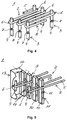
- a possible embodiment of a heat exchanger 18 is shown, which is produced in the method 1.
- the endless plastic tube 5 stretched meander-like is only overmoulded at the wrapping points 6 and the tube plates 15 produced.
- the two tube plates 15 are fixed spaced from one another with a spacer 19 to form a heat exchanger block 20.
- the spacers can for example be brazes or metal rods.
- manifolds 21 are fixed on the plate surfaces 17 in a bonded manner so that the medium to be cooled can be conducted into the heat exchanger tubes 16 and conducted out of the heat exchanger tubes 16.
- Fig. 9 shows the alternatively configured heat exchanger 18, which is produced in the method 1.
- the endless plastic tube 5 stretched meander-like is overmoulded at the wrapping points 6 and at two further opposite sides of the frame 2 and a heat exchanger frame 22produced.
- the heat exchanger frame 22 thus comprises the tube plates 15 and two side walls 23 and frames the heat exchanger tubes 16 on four sides.
- the manifolds 21 are fixed on the plate surfaces 17 with the confluent heat exchanger tubes 16 in a bonded manner so that the medium to be cooled can be distributed into the heat exchanger tubes 16 and collected from the heat exchanger tubes 16.
- the already prefabricated endless plastic tube 5 is used and the method 1 for producing the heat exchanger 18 made of plastic significantly simplified because of this.
- the conventionally necessary arranging and the removing of the core rods is advantageously avoided.
Landscapes
- Engineering & Computer Science (AREA)
- Physics & Mathematics (AREA)
- Thermal Sciences (AREA)
- Mechanical Engineering (AREA)
- General Engineering & Computer Science (AREA)
- Heat-Exchange Devices With Radiators And Conduit Assemblies (AREA)
Abstract
Description
- The invention relates to a method for producing a heat exchanger with a plurality of medium-conducting heat exchanger tubes made of plastic according to the preamble of
Claim 1. The invention additionally relates to a heat exchanger produced according to this method. - Heat exchangers are already known from the prior art and are used for cooling a medium - for example a charge air or a coolant in a motor vehicle. A heat exchanger usually comprises a plurality of heat exchanger tubes in which the medium to be cooled flows. The medium is conducted into the heat exchanger via an inlet manifold and flows through the individual heat exchanger tubes. The heat exchanger tubes open into an outlet manifold and the cooled medium is conducted out of the heat exchanger. In the heat exchanger, a cooling medium - for example ambient air or a coolant - circulates about the heat exchanger tubes from the outside and a heat exchange between the medium to be cooled and the cooling medium takes place. In this way, the medium to be cooled can be cooled in the heat exchanger tubes by a colder cooling medium. The heat exchanger tubes can be produced both from metal - for example from aluminium - and also from plastic. Since plastics usually have a lower heat conductivity than metals, the number of the heat exchanger tubes in the heat exchanger has to be increased in order to achieve an adequate heat transfer between the medium to be cooled and the cooling medium.
- A heat exchanger made of plastic is usually produced in an injection moulding method as described for example in
JP 4398383 B2 - The object of the invention therefore is to state an improved or at least alternative method for producing a heat exchanger of the generic type, with which the described disadvantages are overcome.
- According to the invention, this object is solved through the subject of the
independent Claim 1. Advantageous embodiments are subject of the dependent claims. - The present invention is based on the general idea of using an endless prefabricated tube made of plastic in a method for producing a heat exchanger. Here, the heat exchanger is produced in the method with a plurality of medium-conducting heat exchanger tubes made of plastic, which in each case open into a tube plate at each longitudinal end side. According to the invention, a frame with two needle rows of a plurality of needles spaced parallel to one another is provided initially. About the needles, at least one endless plastic tube is stretched meander-like so that the endless plastic tube is wrapped around the needles at wrapping points. At least two planes located on top of one another produced from the at least one endless plastic tube stretched meander-like and the at least one endless plastic tube stretched meander-like is then overmoulded at least at the wrapping points to the tube plates. Following this, the at least one endless plastic tube is cut open on both sides at the wrapping points and thereby the heat exchanger tubes held in the tube plates produced.
- In the method according to the invention, the at least one endless plastic tube is stretched on a frame, wherein the at least one endless plastic tube is already prefabricated. In order to be able to stretch the endless plastic tube about the needles meander-like the endless plastic tube is practically flexible and can be bent about the needles. Because of this, the conventionally necessary arranging of the core rods for producing the individual heat exchanger tubes is advantageously avoided. The number of the needles in the respective needle row and the number of the planes are determined by the desired number of heat exchanger tubes in the heat exchanger. To simplify the method, the at least two planes can be produced from an individual endless plastic tube stretched meander-like about the needles. The frame including defined planes consisting of the at least endless plastic tube stretched meander-like is placed into a plastic injection mould and overmoulded at least at the wrapping points. In this way, the endless plastic tube is at least partially embedded in the tube plates on both sides. In order to produce a plate surface of the respective tube plate with the confluent heat exchanger tubes, the endless plastic tube is cut open at the wrapping points on both sides and the endless plastic tube divided into the plurality of heat exchanger tubes. Here, a part of the tube plates can for example be cut off and because of this the endless plastic tube also cut open at the wrapping points on both sides. Since the endless plastic tube is embedded in the tube plates, the newly formed heat exchanger tubes open into the respective plate surfaces of the tube plates. Thus, the heat exchanger tubes are already formed following the cutting-open and no further steps for exposing the heat exchanger tubes are necessary. In the method according to the invention, the already prefabricated endless plastic tube is used and the method thereby clearly simplified. In particular, the conventionally necessary arranging of the core rods and their removal is advantageously avoided.
- [Question to the inventors: Is this correct?] In the method, an endless plastic tube with an inner diameter of approximately 0.65 mm and/or an outer diameter of approximately 0.8 mm can be used. In this way, the heat exchanger with suitably dimensioned heat exchanger tubes can be produced with a reduced expenditure.
- In order to be able to fix the endless plastic tube on the needles axially to these, it can be provided that the endless plastic tube is fixed in fixing recesses of the respective needles in a form-fit manner at least in regions. The fixing recesses in the respective needles can for example revolve about the respective needle and be arranged along the needle spaced from one another. Through the fixing recesses, the endless plastic tube can be fixed on the needles in a simplified manner and the individual planes formed from the endless plastic tube stretched meander-like.
- In order to produce overmoulding forms for the two tube plates, before the overmoulding, two holder plates consisting of a plurality of holder plate pieces are arranged in the frame between the two needle rows and in parallel to these. There, the heat exchanger tubes are fixed in a form-fit manner in holder recesses. The holder recesses are formed in the holder plates between the two adjacent holder plate pieces and each of the heat exchanger tube is fixed in the respective holder recess in a a form-fit manner. The dimensions of the holder recesses in the two holder plates are adjusted to the diameter of the endless plastic tube to separate an inner space of the frame from the two needle rows tightly. After this, an overmoulding case can be fixed on each of the two holder plates and around the two needle rows to form two overmoulding forms. Hence, the inner space of the frame is separated from the two needle rows and the wrapping points of the endless tube by the two overmoulding forms. During the overmoulding, the tube plates are formed in the two overmoulding forms and the inner space of the frame is not overmoulded. After the overmoulding, the overmoulding forms can be removed from the frame in known manner.
- During the overmoulding, the endless plastic tube stretched meander-like is overmoulded at least at the wrapping point and the tube plates thus produced on both sides. In order to produce the heat exchanger and protect the heat exchanger tubes from deforming, it can be provided that the two tube plates are braced against one another to form a heat exchanger block using at least one spacer. The spacer can for example be a brace or a metal rod which fixes the two tube plates spaced from one another.
- Alternatively, during the overmoulding, the endless plastic tube stretched meander-like can be overmoulded at the wrapping points and at two further sides of the frame located opposite one another and a heat exchanger frame with the two tube plates connected to one another be produced. The heat exchanger frame thus frames the heat exchanger tubes on four sides and on the sides which are not framed a flow surface for a cooling medium is formed in each case.
- Advantageously it can be provided that a manifold is fixed onto the tube plates in a bonded manner. By way of the respective manifold, the medium to be cooled can be fed into the heat exchanger and conducted out of the heat exchanger. The respective manifold in this case can be fixed on the respective tube plate for example by overmoulding with plastic, by gluing or ultrasound welding.
- In the method according to the invention the already prefabricated endless plastic tube is used and the method for producing the heat exchanger made of plastic significantly simplified because of this. In particular, the conventionally necessary arranging of the core rods and their removal is advantageously avoided.
- The invention also relates to a heat exchanger with a plurality of medium-conducting heat exchanger tubes made of plastic, which in each case open into a tube plate each at a longitudinal end side. According to the invention, the heat exchanger is produced in a method described above. Advantageously it can be provided that the heat exchanger tubes have an inner diameter of approximately 0.65 mm and/or an outer diameter of approximately 0.8 mm.
- Altogether, the heat exchanger can be produced with reduced expenditure and the heat exchange between the medium to be cooled in the heat exchanger tubes and the cooling medium advantageously increased.
- Further important features and advantageous of the invention are obtained from the subclaims, from the drawings and from the associated figure description by way of the drawings.
- It is to be understood that the features mentioned above and still to be explained in the following cannot only be used in the respective combination stated but also in other combinations or by themselves without leaving the scope of the present invention.
- Preferred exemplary embodiments of the invention are shown in the drawings and are explained in more detail in the following description, wherein same reference characters relate to same or similar or functionally same components.
- It shows, in each case schematically
- Fig. 1
- a plane formed by a wrapping of an endless plastic tube in a method according to the invention;
- Fig 2
- a plane formed by wrapping of an endless plastic tube about the needles with a smooth surface in a method according to the invention;
- Fig. 3 and 4
- a plane formed by wrapping of an endless plastic tube fixed in a form-fit manner in fixing recesses in a method according to the invention;
- Fig. 5
- an overmoulding form formed by an overmoulding case and a holder plate consisting of a plurality of holder plate pieces in a method according to the invention;
- Fig. 6 and 7
- a tube plate prior to a cutting-open and after a cutting-open in a method according to the invention;
- Fig. 8 and 9
- possible configurations of heat exchangers produced in a method according to the invention.
- As show in
Fig. 1 , aframe 2 with twoneedles rows 3 spaced parallel from one another is initially provided in themethod 1 according to the invention. Theneedle rows 3 have a plurality ofneedles 4 about which an endlessplastic tube 5 is stretched meander-like. The endlessplastic tube 5 is already prefabricated and flexible so that the endlessplastic tube 5 can be bent about theneedles 4. By using theframe 2 and the endlessplastic tube 5, the conventionally necessary arranging of the core rods for producing the hollow spaces is advantageously avoided. The endlessplastic tube 5 is wrapped about theneedles 4 at wrappingpoints 6 and can be fixed on a smooth surface of theneedles 4 as shown inFig. 2 . Alternatively, the endlessplastic tube 5 can be fixed in a form-fit manner in fixingrecesses 7 of therespective needles 4 in regions as shown inFig. 3 and4 . - The wrapping points 6 arranged spaced from one another along the
respective needles 4 so that a plurality of planes 8 - here only oneplane 8 is shown for the sake of clarity - consisting of the endlessplastic tube 5 can be formed on top of one another. To simplify themethod 1, each of theplanes 8 can be formed by a separateendless tube 5. - As shown in
Fig. 5 , a holder plate 9 consisting of a plurality ofholder plate pieces 10 is arranged in theframe 2 between the twoneedle rows 3 and parallel to these. There, the endlessplastic tube 5 is fixed in a form-fit manner in holder recesses 11 formed in the holder plate 9 between the two adjacentholder plate pieces 10 in a form-fit manner. After this, anovermoulding case 12 is fixed on the holder plate 9 and around theneedle row 3. In this way, the overmoulding form 13 is formed by the holder plate 9 and theovermoulding case 12. The overmoulding form 13 separates tightly an inner space 14 of theframe 2 from the enclosed wrapping points 6 of theendless tube 5. - The
frame 2 with the definedplanes 8 consisting of the endlessplastic tube 5 stretched meander-like and with the overmoulding forms 13 is placed into a plastic injection mould and the endlessplastic tube 5 stretched meander-like is overmoulded at the wrapping points 6 enclosed in the overmoulding forms 13 to form atube plate 15, as shown inFig. 6 . During the overmoulding of the wrapping points 6, the endlessplastic tube 5 is embedded into thetube plate 15 at least in regions and the endless plastic tube is fixed in thetube plate 15 in this manner. After this, the moulding form 13 is removed from the formedtube plate 15. InFig. 7 , thetube plate 15 is now shown after a cutting-open of the endlessplastic tube 5 at the wrapping points 6. During the cutting-open, a part of thetube plate 15 is cut off so that the endlessplastic tube 5 is divided into a plurality ofheat exchanger tubes 16. In this way, aplate surface 17 of thetube plate 15 is formed, into which theheat exchanger tubes 16 individually open. Theheat exchanger tubes 16 are formed even after the cutting-open of thetube plate 15 and the conventionally necessary arranging and the removing of the core rods are advantageously avoided. Themethod 1 is clearly simplified because of this. The desired number of theheat exchanger tubes 16 in this case is determined by the number of theneedles 4 in therespective needle row 3 and the number of theplanes 8. - In
Fig. 8 , a possible embodiment of aheat exchanger 18 is shown, which is produced in themethod 1. Here, during the overmoulding, the endlessplastic tube 5 stretched meander-like is only overmoulded at the wrapping points 6 and thetube plates 15 produced. In order to protect theheat exchanger tubes 16 from deforming, the twotube plates 15 are fixed spaced from one another with aspacer 19 to form aheat exchanger block 20. The spacers can for example be brazes or metal rods. In addition,manifolds 21 are fixed on the plate surfaces 17 in a bonded manner so that the medium to be cooled can be conducted into theheat exchanger tubes 16 and conducted out of theheat exchanger tubes 16. -
Fig. 9 shows the alternatively configuredheat exchanger 18, which is produced in themethod 1. Here, during the overmoulding, the endlessplastic tube 5 stretched meander-like is overmoulded at the wrapping points 6 and at two further opposite sides of theframe 2 and a heat exchanger frame 22produced. The heat exchanger frame 22 thus comprises thetube plates 15 and twoside walls 23 and frames theheat exchanger tubes 16 on four sides. Here, too, themanifolds 21 are fixed on the plate surfaces 17 with the confluentheat exchanger tubes 16 in a bonded manner so that the medium to be cooled can be distributed into theheat exchanger tubes 16 and collected from theheat exchanger tubes 16. - In the
method 1 according to the invention, the already prefabricated endlessplastic tube 5 is used and themethod 1 for producing theheat exchanger 18 made of plastic significantly simplified because of this. In particular, the conventionally necessary arranging and the removing of the core rods is advantageously avoided.
Claims (11)
- A method (1) for producing a heat exchanger (18) with a plurality of medium-conducting heat exchanger tubes (16) made of plastic, which in each case open into a tube plate (17) in each case at a longitudinal end side,
characterized in that- a frame (2) with two needle rows (3) consisting of a plurality of needles (4) spaced parallel from one another is provided,- at least one endless plastic tube (5) is stretched about the needles (4) meander-like so that the endless plastic tube (5) wraps about the needles (4) at wrapping points (6),- at least two planes (8) lying on top of one another are produced from the at least one endless plastic tube (5) stretched meander-like,- the at least one endless plastic tube (5) stretched meander-like is overmoulded with plastic at the wrapping points (6) and thereby the tube plates (15) produced, and- the at least one endless plastic tube (5) is cut open at the wrapping points (6) on both sides and thus the heat exchanger tubes (16) held in the tube plates (15) produced. - The method according to Claim 1,
characterized in that
the at least one endless plastic tube (5) is fixed in a form-fit manner in fixing recesses (7) of the respective needles (4) at least in regions. - The method according to Claim 1 or 2,
characterized in that
the at least two planes (8) are produced from an individual endless plastic tube (5) stretched about the needles (4) meander-like. - The method according to any one of the preceding claims,
characterized in that- before the overmoulding, two holder plates (9) consisting of a plurality of holder plate pieces (10) are arranged in the frame (2) between the two needle rows (3) and parallel to these, and- the endless plastic tube (5) is fixed in holder recesses (11) in a form-fit manner formed between the two adjacent holder plate pieces (10) in a a form-fit manner. - The method according to Claim 4,
characterized in that- before the overmoulding, an overmoulding case (12) is fixed on each of the two holder plates (9) and around the two needle rows (3) to form two overmoulding forms (13), and- during the overmoulding, the tube plates (15) are formed in the two overmoulding forms (13). - The method according to one of the preceding claims 1 to 5,
characterized in that
the two tube plates (15) are braced against one another with at least one spacer (19) to form a heat exchanger block (20). - The method according to one of the preceding claims 1 to 5,
characterized in that
during the overmoulding, the endless plastic tube (5) stretched meander-like is overmoulded at the wrapping points (6) and at two further opposite sides of the frame (2) and thus a heat exchanger frame (22) with the two tube plates (15) connected to one another is produced. - The method according to any one of the preceding claims,
characterized in that
a manifold (21) is fixed on the tube plates (15) in a bonded manner. - The method according to any one of the preceding claims,
characterized in that
an endless plastic tube (5) with an internal diameter of approximately 0.65 mm and/or an outer diameter of approximately 0.8 mm is used. - A heat exchanger (18), with a plurality of medium-conducting heat exchanger tubes (16) made of plastic, which in each case open into a tube plate (15) each at the longitudinal end side,
characterized in that
the heat exchanger (18) is produced in the method (1) according to any one of the preceding claims. - The heat exchanger according to Claim 10,
characterized in that
the heat exchanger tubes (16) have an inner diameter of approximately 0.65 mm and/or an outer diameter of approximately 0.8 mm.
Priority Applications (1)
| Application Number | Priority Date | Filing Date | Title |
|---|---|---|---|
| EP17190572.2A EP3453996A1 (en) | 2017-09-12 | 2017-09-12 | Method for producing a heat exchanger |
Applications Claiming Priority (1)
| Application Number | Priority Date | Filing Date | Title |
|---|---|---|---|
| EP17190572.2A EP3453996A1 (en) | 2017-09-12 | 2017-09-12 | Method for producing a heat exchanger |
Publications (1)
| Publication Number | Publication Date |
|---|---|
| EP3453996A1 true EP3453996A1 (en) | 2019-03-13 |
Family
ID=59856450
Family Applications (1)
| Application Number | Title | Priority Date | Filing Date |
|---|---|---|---|
| EP17190572.2A Withdrawn EP3453996A1 (en) | 2017-09-12 | 2017-09-12 | Method for producing a heat exchanger |
Country Status (1)
| Country | Link |
|---|---|
| EP (1) | EP3453996A1 (en) |
Citations (5)
| Publication number | Priority date | Publication date | Assignee | Title |
|---|---|---|---|---|
| DE1929117A1 (en) * | 1968-06-08 | 1971-02-11 | Dietzsch Hans Joachim | Capillary exchanger |
| EP0291322A1 (en) * | 1987-05-14 | 1988-11-17 | Du Pont Canada Inc. | Process for the manufacture of a tube unit for a heat exchanger |
| US5865244A (en) * | 1997-03-25 | 1999-02-02 | Behr America, Inc. | Plastic header tank matrix and method of making same |
| JP2006200816A (en) * | 2005-01-20 | 2006-08-03 | Calsonic Kansei Corp | Resin-made heat exchanger and its manufacturing method |
| WO2008018712A1 (en) * | 2006-08-11 | 2008-02-14 | Lg Chem, Ltd. | Plastic heat exchanger and method of manufacturing the same |
-
2017
- 2017-09-12 EP EP17190572.2A patent/EP3453996A1/en not_active Withdrawn
Patent Citations (6)
| Publication number | Priority date | Publication date | Assignee | Title |
|---|---|---|---|---|
| DE1929117A1 (en) * | 1968-06-08 | 1971-02-11 | Dietzsch Hans Joachim | Capillary exchanger |
| EP0291322A1 (en) * | 1987-05-14 | 1988-11-17 | Du Pont Canada Inc. | Process for the manufacture of a tube unit for a heat exchanger |
| US5865244A (en) * | 1997-03-25 | 1999-02-02 | Behr America, Inc. | Plastic header tank matrix and method of making same |
| JP2006200816A (en) * | 2005-01-20 | 2006-08-03 | Calsonic Kansei Corp | Resin-made heat exchanger and its manufacturing method |
| JP4398383B2 (en) | 2005-01-20 | 2010-01-13 | カルソニックカンセイ株式会社 | Resin heat exchanger and manufacturing method thereof |
| WO2008018712A1 (en) * | 2006-08-11 | 2008-02-14 | Lg Chem, Ltd. | Plastic heat exchanger and method of manufacturing the same |
Similar Documents
| Publication | Publication Date | Title |
|---|---|---|
| SU736863A3 (en) | Method of manufacturing heat-exchanger | |
| KR101512224B1 (en) | Shell and tube type heat exchanger, and assembling method thereof | |
| US9561563B2 (en) | Method for producing a heat exchanger for a motor vehicle and a heat exchanger for a motor vehicle | |
| JP4108544B2 (en) | Mass concrete pipe cooling method | |
| CN102695853A (en) | Method for producing metallic-sodium-filled engine valve | |
| JP2002306931A5 (en) | ||
| JP6362548B2 (en) | Manufacturing method of spacer for water jacket | |
| DE102007063194A1 (en) | Cell assembly for battery, comprises multiple parallel or serial solitary cells interconnected together, where solitary cells are connected with heat conducting plate | |
| US5318110A (en) | Heat exchanger having internally cooled spacer supports for heat exchange tubes | |
| KR20180123712A (en) | heat transmitter | |
| CN103775233A (en) | Water jacket structure for cylinder head | |
| CN103528402A (en) | Heat exchanger for cooling a fluid of an internal combustion engine, assembly with at least one heat exchanger and method for manufacturing a heat exchanger | |
| KR102199698B1 (en) | Manufacturing method of heat-exchanging module for a shell and tube type heat-exchanger | |
| KR20140049421A (en) | Hollow fiber membrane module and method for repairing the same | |
| DE102012106871A1 (en) | Performing temperature control in tools used for performing e.g. die-casting process of carbon glass-fiber reinforced plastic material, by heating and keeping tools at moderate temperature, cooling and performing surface shaping function | |
| JP6023670B2 (en) | Heat exchanger and heat exchange device | |
| US5154679A (en) | Method of assembling a heat exchanger using a fin retainer | |
| US10415515B2 (en) | Exhaust gas recirculation cooler for an internal combustion engine | |
| CZ285477B6 (en) | Process for producing sections of hollow fibers for for modules of hollow fibers | |
| CN102886667A (en) | Fin lateral assembly fixture of heat exchanger | |
| US9003658B2 (en) | Method for enclosing heat pipe with metal and composite heat pipe thereof | |
| JP6998255B2 (en) | Manufacturing equipment and manufacturing method for tubes with fins for heat exchangers | |
| US8656987B2 (en) | Process for producing heat exchanger tubes and heat exchanger tubes | |
| JPH102636A (en) | Condenser for air conditioning system for vehicle | |
| JP6745520B2 (en) | Spacer manufacturing method |
Legal Events
| Date | Code | Title | Description |
|---|---|---|---|
| PUAI | Public reference made under article 153(3) epc to a published international application that has entered the european phase |
Free format text: ORIGINAL CODE: 0009012 |
|
| AK | Designated contracting states |
Kind code of ref document: A1 Designated state(s): AL AT BE BG CH CY CZ DE DK EE ES FI FR GB GR HR HU IE IS IT LI LT LU LV MC MK MT NL NO PL PT RO RS SE SI SK SM TR |
|
| AX | Request for extension of the european patent |
Extension state: BA ME |
|
| 17P | Request for examination filed |
Effective date: 20190503 |
|
| RBV | Designated contracting states (corrected) |
Designated state(s): AL AT BE BG CH CY CZ DE DK EE ES FI FR GB GR HR HU IE IS IT LI LT LU LV MC MK MT NL NO PL PT RO RS SE SI SK SM TR |
|
| GRAP | Despatch of communication of intention to grant a patent |
Free format text: ORIGINAL CODE: EPIDOSNIGR1 |
|
| STAA | Information on the status of an ep patent application or granted ep patent |
Free format text: STATUS: GRANT OF PATENT IS INTENDED |
|
| INTG | Intention to grant announced |
Effective date: 20200707 |
|
| STAA | Information on the status of an ep patent application or granted ep patent |
Free format text: STATUS: THE APPLICATION IS DEEMED TO BE WITHDRAWN |
|
| 18D | Application deemed to be withdrawn |
Effective date: 20201118 |