EP3453977A1 - Automatic oven with humidity sensor - Google Patents
Automatic oven with humidity sensor Download PDFInfo
- Publication number
- EP3453977A1 EP3453977A1 EP18193464.7A EP18193464A EP3453977A1 EP 3453977 A1 EP3453977 A1 EP 3453977A1 EP 18193464 A EP18193464 A EP 18193464A EP 3453977 A1 EP3453977 A1 EP 3453977A1
- Authority
- EP
- European Patent Office
- Prior art keywords
- humidity
- cooking
- controller
- cooking cavity
- convection fan
- Prior art date
- Legal status (The legal status is an assumption and is not a legal conclusion. Google has not performed a legal analysis and makes no representation as to the accuracy of the status listed.)
- Granted
Links
Images


Classifications
-
- F—MECHANICAL ENGINEERING; LIGHTING; HEATING; WEAPONS; BLASTING
- F24—HEATING; RANGES; VENTILATING
- F24C—DOMESTIC STOVES OR RANGES ; DETAILS OF DOMESTIC STOVES OR RANGES, OF GENERAL APPLICATION
- F24C15/00—Details
- F24C15/32—Arrangements of ducts for hot gases, e.g. in or around baking ovens
- F24C15/322—Arrangements of ducts for hot gases, e.g. in or around baking ovens with forced circulation
- F24C15/327—Arrangements of ducts for hot gases, e.g. in or around baking ovens with forced circulation with air moisturising
-
- F—MECHANICAL ENGINEERING; LIGHTING; HEATING; WEAPONS; BLASTING
- F24—HEATING; RANGES; VENTILATING
- F24C—DOMESTIC STOVES OR RANGES ; DETAILS OF DOMESTIC STOVES OR RANGES, OF GENERAL APPLICATION
- F24C15/00—Details
- F24C15/32—Arrangements of ducts for hot gases, e.g. in or around baking ovens
- F24C15/322—Arrangements of ducts for hot gases, e.g. in or around baking ovens with forced circulation
- F24C15/325—Arrangements of ducts for hot gases, e.g. in or around baking ovens with forced circulation electrically-heated
-
- F—MECHANICAL ENGINEERING; LIGHTING; HEATING; WEAPONS; BLASTING
- F24—HEATING; RANGES; VENTILATING
- F24C—DOMESTIC STOVES OR RANGES ; DETAILS OF DOMESTIC STOVES OR RANGES, OF GENERAL APPLICATION
- F24C7/00—Stoves or ranges heated by electric energy
- F24C7/002—Stoves
-
- G—PHYSICS
- G05—CONTROLLING; REGULATING
- G05D—SYSTEMS FOR CONTROLLING OR REGULATING NON-ELECTRIC VARIABLES
- G05D27/00—Simultaneous control of variables covered by two or more of main groups G05D1/00 - G05D25/00
- G05D27/02—Simultaneous control of variables covered by two or more of main groups G05D1/00 - G05D25/00 characterised by the use of electric means
-
- G—PHYSICS
- G01—MEASURING; TESTING
- G01N—INVESTIGATING OR ANALYSING MATERIALS BY DETERMINING THEIR CHEMICAL OR PHYSICAL PROPERTIES
- G01N25/00—Investigating or analyzing materials by the use of thermal means
- G01N25/56—Investigating or analyzing materials by the use of thermal means by investigating moisture content
-
- G—PHYSICS
- G01—MEASURING; TESTING
- G01N—INVESTIGATING OR ANALYSING MATERIALS BY DETERMINING THEIR CHEMICAL OR PHYSICAL PROPERTIES
- G01N27/00—Investigating or analysing materials by the use of electric, electrochemical, or magnetic means
- G01N27/02—Investigating or analysing materials by the use of electric, electrochemical, or magnetic means by investigating impedance
- G01N27/04—Investigating or analysing materials by the use of electric, electrochemical, or magnetic means by investigating impedance by investigating resistance
- G01N27/048—Investigating or analysing materials by the use of electric, electrochemical, or magnetic means by investigating impedance by investigating resistance for determining moisture content of the material
Definitions
- the present invention generally relates to a cooking appliance, and more specifically, to an oven comprising a humidity detection apparatus.
- a cooking apparatus configured to detect a humidity level of a cooking cavity.
- the apparatus comprises a housing forming the cooking cavity comprising at least one heating element configured to heat the cooking cavity.
- the apparatus further comprises a first temperature sensor in the cooking cavity configured to identify a cooking temperature and a humidity chamber in connection with an exterior surface of the housing.
- a humidity sensing apparatus comprising a humidity sensor is disposed in the humidity chamber.
- a controller is in communication with the heating element, the first temperature sensor and the humidity sensing apparatus.
- the controller is configured to monitor a voltage signal from the humidity sensor and identify a plurality of potential humidity levels based on the voltage signal.
- the controller is further operable to determine an actual humidity level from the plurality of humidity levels based on a system response of the humidity sensor.
- a method for calculating a humidity level in a cooking apparatus comprises heating a food load in a cooking cavity of the cooking apparatus and selectively activating a convection fan in the cooking cavity.
- the method further comprises monitoring a humidity signal detected by a humidity sensing apparatus in response to the activation of the convection fan.
- the method may determine an actual humidity level from a plurality of humidity levels based on a change in the humidity signal.
- a cooking apparatus configured to detect a humidity level of a cooking cavity.
- the apparatus comprises a housing forming the cooking cavity comprising at least one heating element configured to heat the cooking cavity.
- a convection fan and a first temperature sensor are disposed in the cooking cavity.
- the first temperature sensor is configured to identify a cooking temperature of the cooking cavity.
- the apparatus further comprises a humidity chamber in connection with the housing and a humidity sensing apparatus comprising a humidity sensor disposed in the humidity chamber.
- a controller is in communication with the heating element, the convection fan, the first temperature sensor, and the humidity sensing apparatus.
- the controller is configured to monitor a humidity signal from the humidity sensor and identify a plurality of potential humidity levels based on the humidity signal.
- the controller is configured to determine an actual humidity level from the plurality of humidity levels in response to a selective activation of the convection fan.
- the terms "upper,” “lower,” “right,” “left,” “rear,” “front,” “vertical,” “horizontal,” and derivatives thereof shall relate to the device as oriented in FIG. 1 .
- the device may assume various alternative orientations and step sequences, except where expressly specified to the contrary.
- the specific devices and processes illustrated in the attached drawings, and described in the following specification are simply exemplary embodiments of the inventive concepts defined in the appended claims. Hence, specific dimensions and other physical characteristics relating to the embodiments disclosed herein are not to be considered as limiting, unless the claims expressly state otherwise.
- the disclosure provides for a convection oven with an automatic cooking function based on a detection by an absolute humidity sensor.
- the humidity sensor may be incorporated as part of a humidity sensing apparatus.
- the humidity sensing apparatus may be housed in a humidity chamber that may be connected to or extend outward from an exterior surface of a cooking chamber of the oven.
- humidity measurements from the humidity sensing apparatus may be monitored by a controller of the oven to determine a cooking state of a food load in the cooking chamber.
- the disclosure provides for a novel humidity sensing apparatus and various methods for detecting the absolute humidity of the cooking chamber such that the control may provide for a variety of automated cooking functions.
- the oven 10 may be a component of a free-standing range or may be embodied as an in-wall oven assembly (or double oven assembly).
- the oven 10 includes a housing 12 that defines a cooking cavity 14.
- the cooking cavity 14 includes a bottom wall 16 having a pair of side walls 18, 20 and a back wall 22 extending upward to a top wall 24.
- the oven 10 may further include a number of heating elements 26.
- the heating elements may be positioned adjacent the top wall 24 and/or the bottom wall 16.
- the oven 10 comprises a plurality of heating elements 26 comprising e.g. electric bake elements 26a as well as broil elements 26b (schematically shown in figure 2 ).
- the cooking cavity 14 may further comprise one or more oven racks 30, which may be supported on opposite sides by the side walls 18, 20.
- the oven may further comprise an oven light 32 configured to illuminate the cooking cavity 14.
- One or more convection fans 34 may be incorporated in the oven 10.
- the convection fans 34 may be disposed in one or more of the walls 16, 18, 20, 22, 24 of the cooking cavity 14.
- the convection fan 34 may be centrally disposed in the back wall 22 and configured to circulate heat from the heating elements 26.
- the convection fan 34 may further be configured to cause a change or perturbation of a humidity level in the cooking cavity 14 of the oven 10. Such a perturbation may similarly result in a resulting change in a humidity level in a humidity sensing apparatus 36 housed in a humidity chamber 38 in connection with the cooking cavity 14.
- the humidity chamber 38 may be connected to or extend outward from an exterior surface of the housing 12.
- the humidity chamber 38 of the humidity sensing apparatus 36 may be in fluid connection with the cooking cavity 14 via a sensing port 40.
- the sensing port 40 may correspond to an opening or hole to be formed in the back wall 22 of the housing 12 connecting the cooking cavity 14 to an interior volume of the humidity chamber 38.
- the sensing port 40 may provide for controlled passage of heated air from the cooking cavity 14 into the humidity chamber 38.
- the sensing port 40 may comprise an actuator 41 or baffle configured to dilate or selectively adjust an effective size or proportion of the sensing port 40.
- a controller 60 may control the actuator 41 to adjust the convection of air and moisture between the cooking cavity 14 and cooking chamber.
- the air may be convected between the cooking cavity 14 and the humidity chamber 38 by natural currents resulting from temperature gradients and perturbations or indirect circulating currents driven by the convection fan 34 in the cooking cavity 14.
- the air transferred between the cooking cavity 14 and the humidity chamber 38 may not be forced or directly driven by a transfer fan or other devices configured to transfer air directly between the cooking cavity 14 and the humidity chamber 38.
- the oven 10 may limit or avoid buildup of moisture in the humidity chamber 38, which can result in diminished accuracy or wear of the humidity sensing apparatus 36.
- the humidity conditions within the cooking cavity 14 may be similarly experienced in the humidity chamber 38 such that the controller 60 may monitor and identify the moisture or humidity level in the cooking cavity 14.
- the humidity chamber 38 may be significantly insulated from the cooking temperatures in the oven. Accordingly, the heated air that passes into the humidity chamber 38 may be controlled by the actuator 41 adjusting the proportions of the sensing port 40. Accordingly, the temperature conditions within the humidity chamber 38 may be significantly lower than those in the cooking cavity 14 providing for the humidity sensing apparatus 36 to operate at lower temperatures than the cooking cavity 14.
- the control of the temperature or limiting of peak temperatures in the humidity chamber 38 may be particularly important during peak heating conditions (e.g., self-cleaning pyrolytic cycles, etc.).
- the humidity sensing apparatus is discussed in further detail in reference to FIG. 3 .
- the cooking cavity 14 may be accessed via an oven door 42 coupled to the housing 12. Additionally, an interface console 44 may be located above the oven door 42.
- the console 44 may include the user-operated controls 46 for operating the oven 10.
- the controls 46 may comprise tactile keys, membrane switches, toggle switches, buttons, dials, slides or other suitable control mechanisms. In this configuration, a user may utilize the controls 46 to select a food type, cooking configuration, and desired operation (e.g., broiling, baking, etc.) to be executed by the oven 10.
- the interface console 44 may further comprise a display 48 and an audio device 50.
- the display 48 may provide a variety of messages, graphical icons, and other indicators to inform the user of the status of the oven 10.
- the audio device 50 may output audible signals (e.g., a "beep") to alert the user to a condition of the oven 10, or to prompt the user to take an action relating to an operation of the oven 10.
- FIG. 2 a block diagram of the oven 10 is shown demonstrating a controller 60 configured to control various cooking operations of the oven.
- the controller 60 is in communication with the controls 46, the display 48, and the audio device 50 to facilitate various programming steps and notifications identifying operations of the oven 10.
- the controller 60 may further be in communication with the heating elements 26, the convection fan 34, the humidity sensing apparatus 36, and a cooking chamber temperature sensor 62 (e.g., a first temperature sensor) configured to detect a temperature in the cooking cavity 14.
- the controller 60 may respond to signals from the humidity sensing apparatus 36 and the cooking chamber temperature sensor 62 and control the heating elements 26 and the convection fan 34 to provide desired cooking conditions within the cooking cavity 14.
- the controller 60 may be configured to perform computational operations, such as reading data, calculating values, counting elapsed time, executing pre-programmed or automatic cooking programs, and comparing data to predetermined values, either continuously or intermittently, during operation of the oven 10.
- the controller 60 may comprise a communication interface 64, one or more microcontrollers or processors 66, and a memory device 68, as well as other electronic components commonly utilized in the control of electromechanical systems.
- the memory device 68 may include a programmable non-volatile storage device (e.g., electrically erasable programmable read-only memory or EEPROM).
- the memory device 68 may be configured to store and access computerized routines (e.g., firmware or software) executable by the processor 66 and access control parameters used to facilitate one or more automated cooking operations of the oven 10.
- the cooking chamber temperature sensor 62 or first temperature sensor 62 may be positioned in or near the cooking cavity 14 of the oven 10. As illustrated, the first temperature sensor 62 is positioned on the back wall 22 of the cooking cavity 14. The first temperature sensor 62 may be sampled by the controller 60 to periodically sense the temperature in the cooking cavity 14 and communicate temperature signals to the controller 60.
- the first temperature sensor 62 may correspond to a variety of types of temperature probes or sensors. For example, the temperature sensor as discussed herein may correspond to a resistive sensor, such as a Resistance Temperature Detector (RTD) sensor.
- RTD Resistance Temperature Detector
- the interface 64 of the controller 60 is further in communication with the humidity sensing apparatus 36.
- the humidity sensing apparatus 36 may be disposed in the humidity chamber 38 in connection with the cooking cavity 14.
- the humidity sensing apparatus 36 may comprise a humidity sensor 70 and a humidity chamber temperature sensor 72 (e.g., a second temperature sensor).
- the humidity sensor 70 and a humidity chamber temperature sensor 72 may be configured to communicate a humidity signal and temperature signal indicating the conditions in the humidity chamber 38 such that the controller may utilize the signals to control various cooking functions of the oven 10.
- the humidity sensor 70 and a humidity chamber temperature sensor 72 (e.g., the second temperature sensor 72) are discussed further in reference to FIG. 3 .
- the oven chamber temperature sensor 62 and the humidity chamber temperature sensor 72 may be referred to herein as the first temperature sensor 62 and the second temperature sensor 72 for clarity. However, it shall be understood that the identifiers of first, second, etc., are for clarity in reference to the specific elements described in the exemplary embodiments of the detailed description and shall not be considered limiting to the scope of the disclosure.
- the sensing port 40 may provide for controlled passage of air and moisture from the cooking cavity 14 to be communicated into the humidity chamber 38.
- the humidity sensor 70 may comprise a monitoring circuit in communication with the controller 60 via one or more conductive wires 82.
- the humidity sensor 70 may comprise a plurality of thermistors.
- a first thermistor 92a is enclosed in a sealed container with dry air and a second thermistor 92b is exposed to moist air ported from the cooking cavity 14 into the humidity chamber 38 via the sensing port 40.
- the humidity sensing apparatus 36 is operable to communicate a humidity detection signal to the controller 60 to detect the humidity in the cooking cavity 14.
- a detailed embodiment including a circuit diagram of the humidity sensor 70 is shown in FIG. 4 and is discussed later.
- the humidity chamber 38 that houses the humidity sensor 70 may protrude outside an insulation shield 84 or insulation layer of the oven 10 through the back wall 22.
- the arrangement of the sensor humidity chamber 38 protruding through the insulation shield 84 may provide for the temperature in the humidity chamber 38 to be much lower than temperatures present in the cooking cavity 14.
- the humidity sensing apparatus 36 may not require any forced ventilation into the humidity chamber 38 to reliably monitor the humidity in the cooking cavity 14. Avoiding forced convection may be beneficial in some applications by providing accurate humidity monitoring while maintaining simple and economical construction for the humidity sensing apparatus 36. Additionally, operation without forced convection may limit a risk of condensation in the sensor humidity chamber 38, which may otherwise result due to forced convection causing excessive cooling.
- the difference in temperature between the cooking cavity 14 and the humidity chamber 38 may be identified by the controller 60 by monitoring signals from the first temperature sensor 62 (e.g., the cooking chamber temperature sensor) and the second temperature sensor 72 (e.g., the humidity chamber temperature sensor).
- the second temperature sensor 72 may be disposed in the humidity chamber 38 proximate the humidity sensor 70.
- a controller of the humidity sensing apparatus 36 may detect the chamber temperature in the humidity chamber 38 and approximate the humidity in the cooking cavity 14 based on readings of the humidity sensor 70.
- the approximation of the humidity in the cooking cavity 14 may be based on a conversion of the humidity identified in the humidity chamber 38 based on the particular design of the oven 10 and the humidity chamber 38.
- the humidity detected by the humidity sensor 70 may be offset by the temperature difference between the sensor humidity chamber 38 and the cooking cavity 14 indicated by the second temperature sensor 72.
- the humidity sensor 70 may be in communication with the controller 60 via the interface 64 and the conductive wires 82.
- the humidity sensor 70 comprises a plurality of thermistors 92 arranged in series.
- a first thermistor 92a e.g., a sealed thermistor
- a second thermistor 92b e.g., an open thermistor is exposed to moist air.
- the controller 60 may monitor the relative temperature of the humidity chamber 38 in dry conditions with the first thermistor 92a and including humidity associated with the cooking cavity 14 with the second thermistor 92b.
- the thermistors 92 may be operable to output signals processed by the controller 60 to identify the absolute humidity of the air surrounding the humidity sensor 70.
- the controller 60 detects the absolute humidity based on a transduction physical principle. Accordingly, the identification of the absolute humidity in the humidity chamber 38 may be processed by the controller 60 by comparing the thermal conductivity variation of moist air versus water vapor content. For example, a variation in the absolute humidity in the humidity chamber 38 may cause a variation of the thermal conductivity of moist air. In response to the variation in the thermal conductivity, a heat transfer imbalance may be generated between the two thermistors 92a and 92b. Due to this imbalance, the resulting temperatures of the thermistors 92a and 92b will differ. Based on the difference in the temperatures, the voltage difference between a first and second node (conductive contacts 98a and 98b) of the humidity sensor 70 may be measured by controller 60 via a differential amplifier.
- the thermistors 92 may correspond to negative temperature coefficient (NTC) thermistors 92.
- the thermistors 92 may comprise semiconductor materials configured to effect large changes in resistance in response to small changes in temperature. Accordingly, when incorporated in the monitoring circuit 90, the resistance of the thermistors 92a and 92b may change slightly due to small differences in temperature between the sealed thermistor 92a and the open thermistor 92b. Accordingly, the controller 60 may measure the slight differences in the resistances of the thermistors 92a and 92b via the differential amplifier.
- the differential amplifier may be incorporated in the controller 60 or one or more additional circuits in connection with the conductive contacts 98a and 98b of a Wheatstone Bridge Circuit 98.
- a first conductive contact 98a may correspond to a sensor leg 100a.
- the sensor leg 100a may be in connection with the first thermistor 92a and the second thermistor 92b.
- the typical operating temperature of NTC thermistors may be limited to -50°C to approximately 200°C. Accordingly, by housing the monitoring circuit 90 of the humidity sensor 70 in the humidity chamber 38, the temperature of the humidity chamber 38 may be limited below 200°C providing for accurate operation of the thermistors 92.
- the monitoring circuit 90 of the humidity sensor 70 may further comprise a shunt resistor 96 in connection between at least one of the first thermistor 92a and the second thermistor 92b and a ground of the monitoring circuit 90. In this configuration, the controller 60 may also measure a voltage drop across the shunt resistor 96 via a differential amplifier.
- a second conductive contact 98b may correspond to a sensor leg 100b.
- the sensor leg 100b may be in connection with a plurality of reference resistors 102 (e.g. a first reference resistor 102a and a second reference resistor 102b).
- the reference resistors 102a and 102b may correspond to have a comparatively high resistance relative to the thermistors 92.
- the reference resistors 102a and 102b may have a resistance of approximately 20-1000 times the resistance of the thermistors 92a and 92b.
- a reference voltage of the voltage imbalance between the thermistors 92a and 92b may be measured by the differential amplifier (not shown) of the monitoring circuit 90 connected between conductive contacts 98a and 98b.
- the monitoring circuit 90 may further comprise a voltage source 106 in connection with the Wheatstone Bridge Circuit 98.
- the monitoring circuit 90 may be controlled by the controller 60 to operate as a biasing circuit.
- the biasing circuit may operate the thermistors 92 at a temperature above the air within the humidity chamber 38.
- the operating range or working temperature of the monitoring circuit 90 may be configured based on the resistance of the shunt resistor 96, the voltage of the voltage source 106, and the design of the sensing port 40 and the humidity chamber 38 controlling the temperature range in the humidity chamber 38.
- a plurality of characteristic voltage curves 110 of the voltage signal are shown representing the differential voltage V m .
- the curves 110 demonstrate the system response of the humidity sensor 70 measured between conductive contacts 98a and 98b in response to changes in humidity at various temperatures T. As shown, the increasing air temperature decreases a magnitude of a parabolic shape of the voltage curves 110.
- the solutions of Equation 1 model the response of the humidity sensor 70 due to the heat transfer imbalance between thermistors 92a and 92b resulting from the effective humidity difference between the thermistors 92a and 92b.
- Coefficients a, b, c, d, and e are constants related to the specific design of the electronic components of the monitoring circuit 90 and may be identified based on experimental data. Actual values of the aforementioned coefficients can be characterized by placing one or more sensors inside an environment whose temperature and humidity can be accurately controlled, while the sensors output is recorded. The coefficients of the formula are then obtained by fitting the data to the given formula using available fitting methods. Accordingly, the solution of Equation 1 may form a parabola that links the sensor output V m and the current air temperature T with two possible absolute humidity solutions AH+ and AH-.
- the parabolic shape of the voltage curve 110 from Equation 1 results in two possible or potential humidity solutions identifying the absolute humidity AH in the humidity chamber 38 for a single voltage value V m across the nodes 98a and 98b. Accordingly, the voltage output V m supplied to the controller 60 may be ambiguous. However, as discussed in reference to FIGS. 6 and 7 , a disambiguation method may be applied by the controller 60 to identify the humidity level to which the voltage output V m relates or indicates from a plurality (e.g. two possible solutions) of potential humidity levels provided by Equation 1. In this way, the controller 60 may quickly and accurately identify if the voltage output V m corresponds to the first humidity level solution AH+ or second humidity level solution AH-. By identifying the location along the voltage curve 110 that corresponds to the voltage output V m , the controller 60 may accurately identify the actual or true absolute humidity of the humidity chamber 38 and the cooking cavity 14.
- the controller 60 may apply the disambiguation method to identify whether the absolute humidity indicated by the voltage output V m corresponds to the first humidity level AH+ or the second humidity level AH-.
- the disambiguation method may comprise monitoring a change in the voltage output V m in response to pulsing the convection fan 34 of the oven 10. Following the pulsing of the fan 34, the controller 60 may monitor the response of the humidity sensor 70 for signs of signal variation.
- the arrows indicate a change in the voltage output V m over a range of humidity levels.
- the convection fan 34 is activated to perturbate the natural stratification of the humidity in the cooking cavity 14. Accordingly, the pulsing of the convection fan 34 also causes variation in the humidity chamber 38, which is identified in the voltage output V m .
- the absolute humidity AH is below a parabolic vertex 122, 132 of a signal response of the humidity sensor 70 (i.e., 130 g/m 3 )
- the signal response is positive.
- the positive change in the voltage signal is shown as an increase or positive change, which is denoted by the upward directed arrows.
- the controller 60 may differentiate the humidity reading of the humidity sensor 70 above and below the parabolic vertex 122, 132 to accurately identify and distinguish comparable readings along the response curves 120, 130.
- the signal output from the controller 60 may sample the voltage output V m from the humidity sensor 70 five to thirty seconds after commutation of a state (e.g., OFF to ON or ON to OFF) of the convection fan 34. Additionally, because there is a steeper response of the signal when switching from OFF to ON, in an exemplary embodiment, the signal change from the humidity sensor 70 is assessed across the switch-ON event. In this way, the controller 60 may accurately identify the relative location of the voltage output V m along the system response curves 120, 130 to accurately identify the absolute humidity in the humidity chamber 38.
- a state e.g., OFF to ON or ON to OFF
- the controller 60 may similarly mathematically determine whether the voltage output V m corresponds to AH+ or AH- without activating or adjusting the operation of the convection fan 34. For example, during a heating process in the oven 10, the controller may monitor the humidity results in the humidity chamber 38 based on the voltage output V m from the humidity sensor 70. As the cooking cavity 14 increases in humidity during a cooking process, the controller 60 may monitor the voltage output V m . Eventually, if the humidity level exceeds the parabolic vertex 122, voltage output V m may reach a plateau. In some embodiments, the controller 60 may be configured to distinguish between the plateau caused by crossing the parabolic vertex 122 and a plateau caused by a stabilization of the humidity level.
- the controller may distinguish between the plateau caused by crossing the parabolic vertex 122 and a plateau caused by a stabilization of the humidity level based on the first derivative of the voltage output V m .
- the controller 60 may identify first identify a plateau by identifying that the first derivative of the voltage output V m is approximately zero. The approximate zero value of the first derivative may indicate that the voltage output V m is stable.
- the controller 60 may monitor a time period during which the voltage output V m remains substantially unchanged.
- the controller 60 may identify the stable voltage output V m condition or the parabolic vertex 122 (e.g. the local maximum) of the first derivative based on the voltage output V m changing less than a predetermined amount for a first predetermined time. For example, the controller 60 may identify the stable condition in response to the voltage output V m changing less than 5 percent for a first predetermined time of 240 seconds. Specific examples of exemplary times and percentage changes are provided herein for clarity and should not be considered limiting to the disclosure. Accordingly, the controller 60 may first identify the stable or unchanging condition of the voltage output V m and then identify whether the stable condition is caused by a stabilization in humidity or the crossing of the parabolic vertex 122 along the system response curve 120.
- the controller 60 may first identify the stable or unchanging condition of the voltage output V m and then identify whether the stable condition is caused by a stabilization in humidity or the crossing of the parabolic vertex 122 along the system response curve 120.
- the controller 60 may identify the plateau as a stabilization of the humidity level. For example, if after the first predetermined period of time has lapsed, the voltage output V m does not change greater than 5 percent for a second predetermined period of time (e.g. 180 seconds) the controller 60 may identify that the humidity level has stabilized. Further, if after the first predetermined period of time has lapsed, the voltage output V m changes greater than 5 percent or significantly decreases within the second predetermined period of time (e.g. 180 seconds) the controller 60 may identify that the plateau corresponded to the parabolic vertex 122. Accordingly, based on the identification of the parabolic vertex 122, the controller 60 may identify future changes in the voltage output V m indicating the humidity level on the right side of the parabolic vertex 122.
- the controller 60 may verify the plateau by monitoring the voltage output V m for a decrease in a rate of change of humidity. By identifying the decrease in the rate of change of the humidity and the voltage output V m , the plateau may be verified or calculated by the controller 60. In this way, the controller 60 may be configured to identify the voltage output V m from the humidity sensor 70 as corresponding to AH+ while the rate of change of the voltage output V m is positive. Additionally, the controller 60 may be configured to identify the voltage output V m from the humidity sensor 70 as corresponding to AH- while the rate of change of the voltage output V m is negative.
- the term "coupled” in all of its forms, couple, coupling, coupled, etc. generally means the joining of two components (electrical or mechanical) directly or indirectly to one another. Such joining may be stationary in nature or movable in nature. Such joining may be achieved with the two components (electrical or mechanical) and any additional intermediate members being integrally formed as a single unitary body with one another or with the two components. Such joining may be permanent in nature or may be removable or releasable in nature unless otherwise stated.
- elements shown as integrally formed may be constructed of multiple parts or elements shown as multiple parts may be integrally formed, the operation of the interfaces may be reversed or otherwise varied, the length or width of the structures and/or members or connector or other elements of the system may be varied, the nature or number of adjustment positions provided between the elements may be varied.
- the elements and/or assemblies of the system may be constructed from any of a wide variety of materials that provide sufficient strength or durability, in any of a wide variety of colors, textures, and combinations. Accordingly, all such modifications are intended to be included within the scope of the present innovations. Other substitutions, modifications, changes, and omissions may be made in the design, operating conditions, and arrangement of the desired and other exemplary embodiments without departing from the spirit of the present innovations.
Landscapes
- Engineering & Computer Science (AREA)
- Chemical & Material Sciences (AREA)
- Combustion & Propulsion (AREA)
- Mechanical Engineering (AREA)
- General Engineering & Computer Science (AREA)
- Physics & Mathematics (AREA)
- General Physics & Mathematics (AREA)
- Automation & Control Theory (AREA)
- Investigating Or Analyzing Materials By The Use Of Electric Means (AREA)
- Chemical Kinetics & Catalysis (AREA)
- Electrochemistry (AREA)
- Health & Medical Sciences (AREA)
- Life Sciences & Earth Sciences (AREA)
- Analytical Chemistry (AREA)
- Biochemistry (AREA)
- General Health & Medical Sciences (AREA)
- Immunology (AREA)
- Pathology (AREA)
Abstract
Description
- The present invention generally relates to a cooking appliance, and more specifically, to an oven comprising a humidity detection apparatus.
- In at least one aspect, a cooking apparatus configured to detect a humidity level of a cooking cavity is disclosed. The apparatus comprises a housing forming the cooking cavity comprising at least one heating element configured to heat the cooking cavity. The apparatus further comprises a first temperature sensor in the cooking cavity configured to identify a cooking temperature and a humidity chamber in connection with an exterior surface of the housing. A humidity sensing apparatus comprising a humidity sensor is disposed in the humidity chamber. A controller is in communication with the heating element, the first temperature sensor and the humidity sensing apparatus. The controller is configured to monitor a voltage signal from the humidity sensor and identify a plurality of potential humidity levels based on the voltage signal. The controller is further operable to determine an actual humidity level from the plurality of humidity levels based on a system response of the humidity sensor.
- In at least another aspect, a method for calculating a humidity level in a cooking apparatus is disclosed. The method comprises heating a food load in a cooking cavity of the cooking apparatus and selectively activating a convection fan in the cooking cavity. The method further comprises monitoring a humidity signal detected by a humidity sensing apparatus in response to the activation of the convection fan. As a result of the activation of the convection fan, the method may determine an actual humidity level from a plurality of humidity levels based on a change in the humidity signal.
- In at least another aspect, a cooking apparatus configured to detect a humidity level of a cooking cavity is disclosed. The apparatus comprises a housing forming the cooking cavity comprising at least one heating element configured to heat the cooking cavity. A convection fan and a first temperature sensor are disposed in the cooking cavity. The first temperature sensor is configured to identify a cooking temperature of the cooking cavity. The apparatus further comprises a humidity chamber in connection with the housing and a humidity sensing apparatus comprising a humidity sensor disposed in the humidity chamber. A controller is in communication with the heating element, the convection fan, the first temperature sensor, and the humidity sensing apparatus. The controller is configured to monitor a humidity signal from the humidity sensor and identify a plurality of potential humidity levels based on the humidity signal. The controller is configured to determine an actual humidity level from the plurality of humidity levels in response to a selective activation of the convection fan.
- These and other features, advantages, and objects of the present device will be further understood and appreciated by those skilled in the art upon studying the following specification, claims, and appended drawings.
- In the drawings:
-
FIG. 1 is a perspective view of an oven comprising a humidity sensor; -
FIG. 2 is a block diagram of an oven comprising a humidity sensing apparatus in a humidity chamber connected to a housing of the oven; -
FIG. 3 is a detailed cross-sectional diagram of a humidity chamber connected to a housing of an oven; -
FIG. 4 is a schematic diagram of a monitoring circuit of a humidity sensor of an oven; -
FIG. 5 is a plot of a system response of a voltage output from a humidity sensor; -
FIG. 6 is a plot of a simulated system response of a voltage output from a humidity sensor in response to a perturbation of a convection fan; and -
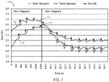
FIG. 7 is a plot of a measured system response of a voltage output from a humidity sensor in response to a perturbation of a convection fan in accordance with the disclosure. - For purposes of description herein the terms "upper," "lower," "right," "left," "rear," "front," "vertical," "horizontal," and derivatives thereof shall relate to the device as oriented in
FIG. 1 . However, it is to be understood that the device may assume various alternative orientations and step sequences, except where expressly specified to the contrary. It is also to be understood that the specific devices and processes illustrated in the attached drawings, and described in the following specification are simply exemplary embodiments of the inventive concepts defined in the appended claims. Hence, specific dimensions and other physical characteristics relating to the embodiments disclosed herein are not to be considered as limiting, unless the claims expressly state otherwise. - In an exemplary embodiment, the disclosure provides for a convection oven with an automatic cooking function based on a detection by an absolute humidity sensor. The humidity sensor may be incorporated as part of a humidity sensing apparatus. The humidity sensing apparatus may be housed in a humidity chamber that may be connected to or extend outward from an exterior surface of a cooking chamber of the oven. As discussed further in the following description, humidity measurements from the humidity sensing apparatus may be monitored by a controller of the oven to determine a cooking state of a food load in the cooking chamber. Accordingly, the disclosure provides for a novel humidity sensing apparatus and various methods for detecting the absolute humidity of the cooking chamber such that the control may provide for a variety of automated cooking functions.
- Referring to
FIG. 1 , there is shown anoven 10. Theoven 10 may be a component of a free-standing range or may be embodied as an in-wall oven assembly (or double oven assembly). Theoven 10 includes ahousing 12 that defines acooking cavity 14. Thecooking cavity 14 includes abottom wall 16 having a pair ofside walls back wall 22 extending upward to atop wall 24. - The
oven 10 may further include a number ofheating elements 26. The heating elements may be positioned adjacent thetop wall 24 and/or thebottom wall 16. In the illustrated embodiment, theoven 10 comprises a plurality ofheating elements 26 comprising e.g.electric bake elements 26a as well asbroil elements 26b (schematically shown infigure 2 ). As utilized in conventional cooking ovens, thecooking cavity 14 may further comprise one ormore oven racks 30, which may be supported on opposite sides by theside walls oven light 32 configured to illuminate thecooking cavity 14. - One or
more convection fans 34 may be incorporated in theoven 10. For example, theconvection fans 34 may be disposed in one or more of thewalls cooking cavity 14. In the illustrated embodiment, theconvection fan 34 may be centrally disposed in theback wall 22 and configured to circulate heat from theheating elements 26. In some embodiments, theconvection fan 34 may further be configured to cause a change or perturbation of a humidity level in thecooking cavity 14 of theoven 10. Such a perturbation may similarly result in a resulting change in a humidity level in a humidity sensingapparatus 36 housed in ahumidity chamber 38 in connection with thecooking cavity 14. Thehumidity chamber 38 may be connected to or extend outward from an exterior surface of thehousing 12. - The
humidity chamber 38 of the humidity sensingapparatus 36 may be in fluid connection with thecooking cavity 14 via asensing port 40. Thesensing port 40 may correspond to an opening or hole to be formed in theback wall 22 of thehousing 12 connecting thecooking cavity 14 to an interior volume of thehumidity chamber 38. In some embodiments, thesensing port 40 may provide for controlled passage of heated air from thecooking cavity 14 into thehumidity chamber 38. Thesensing port 40 may comprise anactuator 41 or baffle configured to dilate or selectively adjust an effective size or proportion of thesensing port 40. In this configuration, acontroller 60 may control theactuator 41 to adjust the convection of air and moisture between thecooking cavity 14 and cooking chamber. - The air may be convected between the
cooking cavity 14 and thehumidity chamber 38 by natural currents resulting from temperature gradients and perturbations or indirect circulating currents driven by theconvection fan 34 in thecooking cavity 14. However, in various embodiments, the air transferred between thecooking cavity 14 and thehumidity chamber 38 may not be forced or directly driven by a transfer fan or other devices configured to transfer air directly between thecooking cavity 14 and thehumidity chamber 38. By avoiding forced convection between thecooking cavity 14 and thehumidity chamber 38, theoven 10 may limit or avoid buildup of moisture in thehumidity chamber 38, which can result in diminished accuracy or wear of thehumidity sensing apparatus 36. In this configuration, the humidity conditions within thecooking cavity 14 may be similarly experienced in thehumidity chamber 38 such that thecontroller 60 may monitor and identify the moisture or humidity level in thecooking cavity 14. - While sharing humidity conditions with the
cooking cavity 14, thehumidity chamber 38 may be significantly insulated from the cooking temperatures in the oven. Accordingly, the heated air that passes into thehumidity chamber 38 may be controlled by theactuator 41 adjusting the proportions of thesensing port 40. Accordingly, the temperature conditions within thehumidity chamber 38 may be significantly lower than those in thecooking cavity 14 providing for thehumidity sensing apparatus 36 to operate at lower temperatures than thecooking cavity 14. The control of the temperature or limiting of peak temperatures in thehumidity chamber 38 may be particularly important during peak heating conditions (e.g., self-cleaning pyrolytic cycles, etc.). The humidity sensing apparatus is discussed in further detail in reference toFIG. 3 . - The
cooking cavity 14 may be accessed via anoven door 42 coupled to thehousing 12. Additionally, aninterface console 44 may be located above theoven door 42. Theconsole 44 may include the user-operatedcontrols 46 for operating theoven 10. Thecontrols 46 may comprise tactile keys, membrane switches, toggle switches, buttons, dials, slides or other suitable control mechanisms. In this configuration, a user may utilize thecontrols 46 to select a food type, cooking configuration, and desired operation (e.g., broiling, baking, etc.) to be executed by theoven 10. Theinterface console 44 may further comprise adisplay 48 and anaudio device 50. Thedisplay 48 may provide a variety of messages, graphical icons, and other indicators to inform the user of the status of theoven 10. Theaudio device 50 may output audible signals (e.g., a "beep") to alert the user to a condition of theoven 10, or to prompt the user to take an action relating to an operation of theoven 10. - Referring now to
FIG. 2 , a block diagram of theoven 10 is shown demonstrating acontroller 60 configured to control various cooking operations of the oven. Thecontroller 60 is in communication with thecontrols 46, thedisplay 48, and theaudio device 50 to facilitate various programming steps and notifications identifying operations of theoven 10. Thecontroller 60 may further be in communication with theheating elements 26, theconvection fan 34, thehumidity sensing apparatus 36, and a cooking chamber temperature sensor 62 (e.g., a first temperature sensor) configured to detect a temperature in thecooking cavity 14. In this configuration, thecontroller 60 may respond to signals from thehumidity sensing apparatus 36 and the cookingchamber temperature sensor 62 and control theheating elements 26 and theconvection fan 34 to provide desired cooking conditions within thecooking cavity 14. - In general, the
controller 60 may be configured to perform computational operations, such as reading data, calculating values, counting elapsed time, executing pre-programmed or automatic cooking programs, and comparing data to predetermined values, either continuously or intermittently, during operation of theoven 10. Accordingly, thecontroller 60 may comprise acommunication interface 64, one or more microcontrollers orprocessors 66, and amemory device 68, as well as other electronic components commonly utilized in the control of electromechanical systems. Thememory device 68 may include a programmable non-volatile storage device (e.g., electrically erasable programmable read-only memory or EEPROM). Thememory device 68 may be configured to store and access computerized routines (e.g., firmware or software) executable by theprocessor 66 and access control parameters used to facilitate one or more automated cooking operations of theoven 10. - The cooking
chamber temperature sensor 62 orfirst temperature sensor 62 may be positioned in or near thecooking cavity 14 of theoven 10. As illustrated, thefirst temperature sensor 62 is positioned on theback wall 22 of thecooking cavity 14. Thefirst temperature sensor 62 may be sampled by thecontroller 60 to periodically sense the temperature in thecooking cavity 14 and communicate temperature signals to thecontroller 60. Thefirst temperature sensor 62 may correspond to a variety of types of temperature probes or sensors. For example, the temperature sensor as discussed herein may correspond to a resistive sensor, such as a Resistance Temperature Detector (RTD) sensor. - The
interface 64 of thecontroller 60 is further in communication with thehumidity sensing apparatus 36. Thehumidity sensing apparatus 36 may be disposed in thehumidity chamber 38 in connection with thecooking cavity 14. Thehumidity sensing apparatus 36 may comprise ahumidity sensor 70 and a humidity chamber temperature sensor 72 (e.g., a second temperature sensor). Thehumidity sensor 70 and a humiditychamber temperature sensor 72 may be configured to communicate a humidity signal and temperature signal indicating the conditions in thehumidity chamber 38 such that the controller may utilize the signals to control various cooking functions of theoven 10. Thehumidity sensor 70 and a humidity chamber temperature sensor 72 (e.g., the second temperature sensor 72) are discussed further in reference toFIG. 3 . The ovenchamber temperature sensor 62 and the humiditychamber temperature sensor 72 may be referred to herein as thefirst temperature sensor 62 and thesecond temperature sensor 72 for clarity. However, it shall be understood that the identifiers of first, second, etc., are for clarity in reference to the specific elements described in the exemplary embodiments of the detailed description and shall not be considered limiting to the scope of the disclosure. - Referring now to
FIG. 3 , a side cross-sectional view of thehumidity sensing apparatus 36 is shown in connection with thecooking cavity 14. In some embodiments, thesensing port 40 may provide for controlled passage of air and moisture from thecooking cavity 14 to be communicated into thehumidity chamber 38. To measure the moisture in thehumidity chamber 38, thehumidity sensor 70 may comprise a monitoring circuit in communication with thecontroller 60 via one or moreconductive wires 82. In an exemplary embodiment, thehumidity sensor 70 may comprise a plurality of thermistors. In such embodiments, a first thermistor 92a is enclosed in a sealed container with dry air and a second thermistor 92b is exposed to moist air ported from thecooking cavity 14 into thehumidity chamber 38 via thesensing port 40. In this configuration, thehumidity sensing apparatus 36 is operable to communicate a humidity detection signal to thecontroller 60 to detect the humidity in thecooking cavity 14. A detailed embodiment including a circuit diagram of thehumidity sensor 70 is shown inFIG. 4 and is discussed later. - In an exemplary embodiment, the
humidity chamber 38 that houses thehumidity sensor 70 may protrude outside aninsulation shield 84 or insulation layer of theoven 10 through theback wall 22. The arrangement of thesensor humidity chamber 38 protruding through theinsulation shield 84 may provide for the temperature in thehumidity chamber 38 to be much lower than temperatures present in thecooking cavity 14. Additionally, in this configuration, thehumidity sensing apparatus 36 may not require any forced ventilation into thehumidity chamber 38 to reliably monitor the humidity in thecooking cavity 14. Avoiding forced convection may be beneficial in some applications by providing accurate humidity monitoring while maintaining simple and economical construction for thehumidity sensing apparatus 36. Additionally, operation without forced convection may limit a risk of condensation in thesensor humidity chamber 38, which may otherwise result due to forced convection causing excessive cooling. - In operation, the difference in temperature between the
cooking cavity 14 and thehumidity chamber 38 may be identified by thecontroller 60 by monitoring signals from the first temperature sensor 62 (e.g., the cooking chamber temperature sensor) and the second temperature sensor 72 (e.g., the humidity chamber temperature sensor). As previously discussed, thesecond temperature sensor 72 may be disposed in thehumidity chamber 38 proximate thehumidity sensor 70. In this configuration, a controller of thehumidity sensing apparatus 36 may detect the chamber temperature in thehumidity chamber 38 and approximate the humidity in thecooking cavity 14 based on readings of thehumidity sensor 70. The approximation of the humidity in thecooking cavity 14 may be based on a conversion of the humidity identified in thehumidity chamber 38 based on the particular design of theoven 10 and thehumidity chamber 38. To improve accuracy, the humidity detected by thehumidity sensor 70 may be offset by the temperature difference between thesensor humidity chamber 38 and thecooking cavity 14 indicated by thesecond temperature sensor 72. - Referring to
FIG. 4 , a circuit diagram of a monitoring circuit 90 forming thehumidity sensor 70 is shown. Thehumidity sensor 70 may be in communication with thecontroller 60 via theinterface 64 and theconductive wires 82. In an exemplary embodiment, thehumidity sensor 70 comprises a plurality of thermistors 92 arranged in series. A first thermistor 92a (e.g., a sealed thermistor) may be enclosed in a sealed container with dry air. A second thermistor 92b (e.g., an open thermistor) is exposed to moist air. In this configuration, thecontroller 60 may monitor the relative temperature of thehumidity chamber 38 in dry conditions with the first thermistor 92a and including humidity associated with thecooking cavity 14 with the second thermistor 92b. In this arrangement, the thermistors 92 may be operable to output signals processed by thecontroller 60 to identify the absolute humidity of the air surrounding thehumidity sensor 70. - In operation, the
controller 60 detects the absolute humidity based on a transduction physical principle. Accordingly, the identification of the absolute humidity in thehumidity chamber 38 may be processed by thecontroller 60 by comparing the thermal conductivity variation of moist air versus water vapor content. For example, a variation in the absolute humidity in thehumidity chamber 38 may cause a variation of the thermal conductivity of moist air. In response to the variation in the thermal conductivity, a heat transfer imbalance may be generated between the two thermistors 92a and 92b. Due to this imbalance, the resulting temperatures of the thermistors 92a and 92b will differ. Based on the difference in the temperatures, the voltage difference between a first and second node (conductive contacts humidity sensor 70 may be measured bycontroller 60 via a differential amplifier. - The thermistors 92 may correspond to negative temperature coefficient (NTC) thermistors 92. In this configuration, the thermistors 92 may comprise semiconductor materials configured to effect large changes in resistance in response to small changes in temperature. Accordingly, when incorporated in the monitoring circuit 90, the resistance of the thermistors 92a and 92b may change slightly due to small differences in temperature between the sealed thermistor 92a and the open thermistor 92b. Accordingly, the
controller 60 may measure the slight differences in the resistances of the thermistors 92a and 92b via the differential amplifier. The differential amplifier may be incorporated in thecontroller 60 or one or more additional circuits in connection with theconductive contacts Wheatstone Bridge Circuit 98. A firstconductive contact 98a may correspond to asensor leg 100a. Thesensor leg 100a may be in connection with the first thermistor 92a and the second thermistor 92b. - The typical operating temperature of NTC thermistors may be limited to -50°C to approximately 200°C. Accordingly, by housing the monitoring circuit 90 of the
humidity sensor 70 in thehumidity chamber 38, the temperature of thehumidity chamber 38 may be limited below 200°C providing for accurate operation of the thermistors 92. In some embodiments, the monitoring circuit 90 of thehumidity sensor 70 may further comprise ashunt resistor 96 in connection between at least one of the first thermistor 92a and the second thermistor 92b and a ground of the monitoring circuit 90. In this configuration, thecontroller 60 may also measure a voltage drop across theshunt resistor 96 via a differential amplifier. - A second
conductive contact 98b may correspond to asensor leg 100b. Thesensor leg 100b may be in connection with a plurality of reference resistors 102 (e.g. a first reference resistor 102a and a second reference resistor 102b). The reference resistors 102a and 102b may correspond to have a comparatively high resistance relative to the thermistors 92. For example, the reference resistors 102a and 102b may have a resistance of approximately 20-1000 times the resistance of the thermistors 92a and 92b. In this configuration, a reference voltage of the voltage imbalance between the thermistors 92a and 92b may be measured by the differential amplifier (not shown) of the monitoring circuit 90 connected betweenconductive contacts - The monitoring circuit 90 may further comprise a
voltage source 106 in connection with theWheatstone Bridge Circuit 98. In this configuration, the monitoring circuit 90 may be controlled by thecontroller 60 to operate as a biasing circuit. The biasing circuit may operate the thermistors 92 at a temperature above the air within thehumidity chamber 38. The operating range or working temperature of the monitoring circuit 90 may be configured based on the resistance of theshunt resistor 96, the voltage of thevoltage source 106, and the design of thesensing port 40 and thehumidity chamber 38 controlling the temperature range in thehumidity chamber 38. - Referring to
FIG. 5 , a plurality of characteristic voltage curves 110 of the voltage signal are shown representing the differential voltage Vm. Thecurves 110 demonstrate the system response of thehumidity sensor 70 measured betweenconductive contacts voltage curve 110 may further be represented by equation 1 as follows:
- The solutions of Equation 1 model the response of the
humidity sensor 70 due to the heat transfer imbalance between thermistors 92a and 92b resulting from the effective humidity difference between the thermistors 92a and 92b. Coefficients a, b, c, d, and e are constants related to the specific design of the electronic components of the monitoring circuit 90 and may be identified based on experimental data. Actual values of the aforementioned coefficients can be characterized by placing one or more sensors inside an environment whose temperature and humidity can be accurately controlled, while the sensors output is recorded. The coefficients of the formula are then obtained by fitting the data to the given formula using available fitting methods. Accordingly, the solution of Equation 1 may form a parabola that links the sensor output Vm and the current air temperature T with two possible absolute humidity solutions AH+ and AH-. - As shown in
FIG. 5 , the parabolic shape of thevoltage curve 110 from Equation 1 results in two possible or potential humidity solutions identifying the absolute humidity AH in thehumidity chamber 38 for a single voltage value Vm across thenodes controller 60 may be ambiguous. However, as discussed in reference toFIGS. 6 and7 , a disambiguation method may be applied by thecontroller 60 to identify the humidity level to which the voltage output Vm relates or indicates from a plurality (e.g. two possible solutions) of potential humidity levels provided by Equation 1. In this way, thecontroller 60 may quickly and accurately identify if the voltage output Vm corresponds to the first humidity level solution AH+ or second humidity level solution AH-. By identifying the location along thevoltage curve 110 that corresponds to the voltage output Vm, thecontroller 60 may accurately identify the actual or true absolute humidity of thehumidity chamber 38 and thecooking cavity 14. - Referring now to
FIGS. 6 and7 atheoretical system response 120 of the voltage output Vm and a measuredsystem response 130 of the voltage output Vm are shown, respectively, demonstrating a disambiguation method for thehumidity sensor 70. Thecontroller 60 may apply the disambiguation method to identify whether the absolute humidity indicated by the voltage output Vm corresponds to the first humidity level AH+ or the second humidity level AH-. For example, the disambiguation method may comprise monitoring a change in the voltage output Vm in response to pulsing theconvection fan 34 of theoven 10. Following the pulsing of thefan 34, thecontroller 60 may monitor the response of thehumidity sensor 70 for signs of signal variation. - As illustrated in
FIGS. 6 and7 , the arrows indicate a change in the voltage output Vm over a range of humidity levels. For each of the arrows shown on the measuredresponse curve 130, theconvection fan 34 is activated to perturbate the natural stratification of the humidity in thecooking cavity 14. Accordingly, the pulsing of theconvection fan 34 also causes variation in thehumidity chamber 38, which is identified in the voltage output Vm. When the absolute humidity AH is below aparabolic vertex parabolic vertex controller 60 may differentiate the humidity reading of thehumidity sensor 70 above and below theparabolic vertex - In order to increase the reliability of the humidity variation caused by the perturbation of the
convection fan 34, the signal output from thecontroller 60 may sample the voltage output Vm from thehumidity sensor 70 five to thirty seconds after commutation of a state (e.g., OFF to ON or ON to OFF) of theconvection fan 34. Additionally, because there is a steeper response of the signal when switching from OFF to ON, in an exemplary embodiment, the signal change from thehumidity sensor 70 is assessed across the switch-ON event. In this way, thecontroller 60 may accurately identify the relative location of the voltage output Vm along the system response curves 120, 130 to accurately identify the absolute humidity in thehumidity chamber 38. - Referring again to
FIG. 6 , thecontroller 60 may similarly mathematically determine whether the voltage output Vm corresponds to AH+ or AH- without activating or adjusting the operation of theconvection fan 34. For example, during a heating process in theoven 10, the controller may monitor the humidity results in thehumidity chamber 38 based on the voltage output Vm from thehumidity sensor 70. As thecooking cavity 14 increases in humidity during a cooking process, thecontroller 60 may monitor the voltage output Vm. Eventually, if the humidity level exceeds theparabolic vertex 122, voltage output Vm may reach a plateau. In some embodiments, thecontroller 60 may be configured to distinguish between the plateau caused by crossing theparabolic vertex 122 and a plateau caused by a stabilization of the humidity level. - The controller may distinguish between the plateau caused by crossing the
parabolic vertex 122 and a plateau caused by a stabilization of the humidity level based on the first derivative of the voltage output Vm. For example, thecontroller 60 may identify first identify a plateau by identifying that the first derivative of the voltage output Vm is approximately zero. The approximate zero value of the first derivative may indicate that the voltage output Vm is stable. Upon identifying the plateau, thecontroller 60 may monitor a time period during which the voltage output Vm remains substantially unchanged. - The
controller 60 may identify the stable voltage output Vm condition or the parabolic vertex 122 (e.g. the local maximum) of the first derivative based on the voltage output Vm changing less than a predetermined amount for a first predetermined time. For example, thecontroller 60 may identify the stable condition in response to the voltage output Vm changing less than 5 percent for a first predetermined time of 240 seconds. Specific examples of exemplary times and percentage changes are provided herein for clarity and should not be considered limiting to the disclosure. Accordingly, thecontroller 60 may first identify the stable or unchanging condition of the voltage output Vm and then identify whether the stable condition is caused by a stabilization in humidity or the crossing of theparabolic vertex 122 along thesystem response curve 120. - If the
controller 60 identifies that the voltage output Vm is unchanged for greater than a second predetermined period of time, thecontroller 60 may identify the plateau as a stabilization of the humidity level. For example, if after the first predetermined period of time has lapsed, the voltage output Vm does not change greater than 5 percent for a second predetermined period of time (e.g. 180 seconds) thecontroller 60 may identify that the humidity level has stabilized. Further, if after the first predetermined period of time has lapsed, the voltage output Vm changes greater than 5 percent or significantly decreases within the second predetermined period of time (e.g. 180 seconds) thecontroller 60 may identify that the plateau corresponded to theparabolic vertex 122. Accordingly, based on the identification of theparabolic vertex 122, thecontroller 60 may identify future changes in the voltage output Vm indicating the humidity level on the right side of theparabolic vertex 122. - Following the identification of the plateau corresponding to the
parabolic vertex 122, thecontroller 60 may verify the plateau by monitoring the voltage output Vm for a decrease in a rate of change of humidity. By identifying the decrease in the rate of change of the humidity and the voltage output Vm, the plateau may be verified or calculated by thecontroller 60. In this way, thecontroller 60 may be configured to identify the voltage output Vm from thehumidity sensor 70 as corresponding to AH+ while the rate of change of the voltage output Vm is positive. Additionally, thecontroller 60 may be configured to identify the voltage output Vm from thehumidity sensor 70 as corresponding to AH- while the rate of change of the voltage output Vm is negative. - It will be understood by one having ordinary skill in the art that construction of the described device and other components is not limited to any specific material. Other exemplary embodiments of the device disclosed herein may be formed from a wide variety of materials unless described otherwise herein.
- For purposes of this disclosure, the term "coupled" (in all of its forms, couple, coupling, coupled, etc.) generally means the joining of two components (electrical or mechanical) directly or indirectly to one another. Such joining may be stationary in nature or movable in nature. Such joining may be achieved with the two components (electrical or mechanical) and any additional intermediate members being integrally formed as a single unitary body with one another or with the two components. Such joining may be permanent in nature or may be removable or releasable in nature unless otherwise stated.
- It is also important to note that the construction and arrangement of the elements of the device as shown in the exemplary embodiments is illustrative only. Although only a few embodiments of the present innovations have been described in detail in this disclosure, those skilled in the art who review this disclosure will readily appreciate that many modifications are possible (e.g., variations in sizes, dimensions, structures, shapes and proportions of the various elements, values of parameters, mounting arrangements, use of materials, colors, orientations, etc.) without materially departing from the novel teachings and advantages of the subject matter recited. For example, elements shown as integrally formed may be constructed of multiple parts or elements shown as multiple parts may be integrally formed, the operation of the interfaces may be reversed or otherwise varied, the length or width of the structures and/or members or connector or other elements of the system may be varied, the nature or number of adjustment positions provided between the elements may be varied. It should be noted that the elements and/or assemblies of the system may be constructed from any of a wide variety of materials that provide sufficient strength or durability, in any of a wide variety of colors, textures, and combinations. Accordingly, all such modifications are intended to be included within the scope of the present innovations. Other substitutions, modifications, changes, and omissions may be made in the design, operating conditions, and arrangement of the desired and other exemplary embodiments without departing from the spirit of the present innovations.
- It will be understood that any described processes or steps within described processes may be combined with other disclosed processes or steps to form structures within the scope of the present device. The exemplary structures and processes disclosed herein are for illustrative purposes and are not to be construed as limiting.
- It is also to be understood that variations and modifications can be made on the aforementioned structures and methods without departing from the concepts of the present device, and further it is to be understood that such concepts are intended to be covered by the following claims unless these claims by their language expressly state otherwise.
- The above description is considered that of the illustrated embodiments only. Modifications of the device will occur to those skilled in the art and to those who make or use the device. Therefore, it is understood that the embodiments shown in the drawings and described above is merely for illustrative purposes and not intended to limit the scope of the device, which is defined by the following claims as interpreted according to the principles of patent law, including the Doctrine of Equivalents.
Claims (13)
- A cooking apparatus (10) configured to detect a humidity level of a cooking cavity (14) comprising:a housing (12) forming the cooking cavity (14) comprising at least one heating element (26) configured to heat the cooking cavity (14);a first temperature sensor (62) arranged in the cooking cavity (14) configured to identify a cooking temperature;a humidity chamber (38) in connection with an exterior surface of the housing (12);a humidity sensing apparatus (36) comprising a humidity sensor (70) disposed in the humidity chamber (38); anda controller (60) in communication with the heating element (26), the first temperature sensor (62), and the humidity sensing apparatus (36), wherein the controller is configured to:monitor a voltage signal from the humidity sensor (70);identify a plurality of potential humidity levels based on the voltage signal;determine an actual humidity level from the plurality of humidity levels based on a system response of the humidity sensor (70)a convection fan (34) disposed in the cooking cavity (14) and in communication with the controller (60)wherein the controller (60) is further configured to determine said actual humidity level by monitoring the voltage signal in response to a selective activation of said convection fan (34).
- The cooking apparatus (10) according to claim 1, wherein the controller (60) is configured to identify the actual humidity level by identifying an increase or a decrease of the voltage signal in response to the selective activation of the convection fan (34).
- The cooking apparatus (10) according to claim 1 or 2, wherein the controller (60) is further configured to:
calculate a rate of change of the voltage signal to determine the actual humidity level. - The cooking apparatus (10) according to claim 3, wherein the controller (60) is further configured to:
identify the actual humidity level from the plurality of humidity levels by calculating and identifying a change in the rate of change of the voltage signal from positive to negative. - The cooking apparatus (10) according to any one of claims 1-4, wherein the humidity chamber (38) is in fluid communication with the cooking cavity (14) via a sensing port (40).
- The cooking apparatus (10) according to any one of claims 1-5, further comprising:
an insulating layer (84) connected to the housing (12) and disposed between the cooking cavity (14) and the humidity chamber (38). - The cooking apparatus (10) according to any one of claims 1-6, wherein the humidity sensing apparatus (36) further comprises a second temperature sensor (72) disposed in the humidity chamber (38).
- The cooking apparatus (10) according to claim 7, wherein the controller (60) is further configured to:
calculate the cooking humidity level in the cooking cavity (14) based on the actual humidity level and a temperature difference between the first temperature sensor (62) and the second temperature sensor (72). - A method for calculating a humidity level in a cooking apparatus, the method comprising:providing a cooking apparatus (10) according to any one of claims 1-8;heating a food load in a cooking cavity (14) of the cooking apparatus (10);monitoring a humidity signal detected by a humidity sensing apparatus (36) of the cooking apparatus (10);selectively activating a convection fan (34) of the cooking apparatus (10), said convection fan being arranged in the cooking cavity (14);determining an actual humidity level from a plurality of humidity levels based on a change in the humidity signal resulting from the selective activation of the convection fan (34).
- The method according to claim 9, wherein the determining the actual humidity from the plurality of humidity levels comprises identifying a positive or negative change in the humidity signal in response to the activation of the convection fan (34).
- The method according to claim 10, wherein the plurality of humidity levels correspond to a first humidity level and a second humidity level.
- The method according to claim 11, wherein the method further comprises:
identifying the actual humidity level as the first humidity level in response to a positive change in the humidity signal occurring due to the activation of the convection fan (34). - The method according to claim 11, wherein the method further comprises:
identifying the actual humidity level as the second humidity level in response to a negative change in the humidity signal occurring due to the activation of the convection fan (34).
Applications Claiming Priority (1)
| Application Number | Priority Date | Filing Date | Title |
|---|---|---|---|
| US15/702,331 US10731869B2 (en) | 2017-09-12 | 2017-09-12 | Automatic oven with humidity sensor |
Publications (2)
| Publication Number | Publication Date |
|---|---|
| EP3453977A1 true EP3453977A1 (en) | 2019-03-13 |
| EP3453977B1 EP3453977B1 (en) | 2020-08-26 |
Family
ID=63578973
Family Applications (1)
| Application Number | Title | Priority Date | Filing Date |
|---|---|---|---|
| EP18193464.7A Active EP3453977B1 (en) | 2017-09-12 | 2018-09-10 | Cooking apparatus with humidity sensor and method for calculating a humidity level in such an oven |
Country Status (2)
| Country | Link |
|---|---|
| US (2) | US10731869B2 (en) |
| EP (1) | EP3453977B1 (en) |
Cited By (2)
| Publication number | Priority date | Publication date | Assignee | Title |
|---|---|---|---|---|
| CN110326980A (en) * | 2019-05-24 | 2019-10-15 | 上海国为食品有限公司 | Using have squirt with the food materials annealing device of distance measurement function heat treatment food materials method |
| CN110507209A (en) * | 2019-08-28 | 2019-11-29 | 惠而浦(中国)股份有限公司 | A kind of intelligent cooking method and the intelligent cooking utensil with probe |
Families Citing this family (6)
| Publication number | Priority date | Publication date | Assignee | Title |
|---|---|---|---|---|
| EP3412973B1 (en) * | 2017-06-07 | 2024-02-28 | Electrolux Appliances Aktiebolag | Oven comprising an assembly for detecting operating parameters within the oven cavity |
| CN212346260U (en) | 2019-02-26 | 2021-01-15 | 沙克忍者运营有限责任公司 | Cooking system capable of being positioned on a support surface and mountable cooking system |
| CN113491454B (en) | 2020-04-06 | 2026-04-14 | 尚科宁家运营有限公司 | Cooking system positionable on a support surface |
| US11882956B2 (en) | 2021-05-28 | 2024-01-30 | Whirlpool Corporation | Cooking adjustment system |
| US12383097B2 (en) | 2021-06-14 | 2025-08-12 | Sharkninja Operating Llc | Temperature controlled accessory for countertop cooking system |
| US20240337616A1 (en) * | 2021-07-28 | 2024-10-10 | Breville Pty Limited | Cooking Appliance and Humidity Sensor for Same |
Citations (4)
| Publication number | Priority date | Publication date | Assignee | Title |
|---|---|---|---|---|
| EP0021225A1 (en) * | 1979-06-14 | 1981-01-07 | Kabushiki Kaisha Shibaura Denshi Seisakusho | Humidity measuring method and hygrometer to carry out the method |
| US4911357A (en) * | 1988-04-11 | 1990-03-27 | Shibaura Electronics Company, Ltd. | Humidity controller utilizing absolute humidity |
| US20020149486A1 (en) * | 2000-07-19 | 2002-10-17 | Lee Don Hee | Absolute humidity sensor |
| US8695487B2 (en) * | 2009-04-16 | 2014-04-15 | Sharp Kabushiki Kaisha | Cooking appliance |
Family Cites Families (18)
| Publication number | Priority date | Publication date | Assignee | Title |
|---|---|---|---|---|
| JPS57134627A (en) | 1981-02-12 | 1982-08-19 | Matsushita Electric Ind Co Ltd | Heater for food |
| JPS5875629A (en) | 1981-10-30 | 1983-05-07 | Matsushita Electric Ind Co Ltd | Automatic heating device with sensor |
| JPS5919813A (en) | 1982-07-26 | 1984-02-01 | Oval Eng Co Ltd | Vibration compensating device for vortex flow meter |
| US4587393A (en) | 1984-01-05 | 1986-05-06 | Matsushita Electric Industrial Co., Ltd. | Heating apparatus having a sensor for terminating operation |
| JPS59191813A (en) | 1984-03-27 | 1984-10-31 | Matsushita Electric Ind Co Ltd | food heater |
| JPS6258893U (en) | 1985-09-30 | 1987-04-11 | ||
| US5792938A (en) | 1996-12-13 | 1998-08-11 | Panametrics, Inc. | Humidity sensor with differential thermal detection and method of sensing |
| FR2849167B1 (en) * | 2002-12-23 | 2005-10-21 | Premark Feg Llc | OVEN FOR COOKING FOOD |
| DE60334571D1 (en) | 2002-12-23 | 2010-11-25 | Premark Feg Llc | OVEN FOR COOKING FOODSTUFFS |
| DE10335295B4 (en) | 2003-07-28 | 2008-02-21 | Igv Institut Für Getreideverarbeitung Gmbh | Method and device for controlling baking parameters |
| DE102004056839A1 (en) | 2004-11-25 | 2006-06-01 | Miele & Cie. Kg | Oven with a Wrasenkanal in which a catalyst and a gas sensor are arranged |
| WO2007077160A2 (en) | 2005-12-30 | 2007-07-12 | Arcelik Anonim Sirketi | Oven with sensor |
| DE202007010358U1 (en) | 2007-07-25 | 2007-09-20 | Igv Institut Für Getreideverarbeitung Gmbh | Device for controlling baking parameters |
| US8415591B2 (en) * | 2010-04-28 | 2013-04-09 | Whirlpool Corporation | Oven with low-temperature self-cleaning mode |
| IT1399944B1 (en) | 2010-05-11 | 2013-05-09 | Giorik Spa | COOKING OVEN WITH STEAM CONVENTION EQUIPPED WITH A HUMIDITY DETECTION AND ADJUSTMENT SYSTEM |
| DE102010061472A1 (en) | 2010-12-22 | 2012-06-28 | Miele & Cie. Kg | Cooking appliance |
| US11168894B2 (en) | 2011-05-20 | 2021-11-09 | Premark Feg L.L.C. | Combination cooking oven with operator friendly humidity control |
| EP3365605B1 (en) * | 2015-10-22 | 2020-04-08 | Electrolux Appliances Aktiebolag | Method and household appliance for controlling humidity |
-
2017
- 2017-09-12 US US15/702,331 patent/US10731869B2/en active Active
-
2018
- 2018-09-10 EP EP18193464.7A patent/EP3453977B1/en active Active
-
2020
- 2020-06-26 US US16/913,211 patent/US11739948B2/en active Active
Patent Citations (4)
| Publication number | Priority date | Publication date | Assignee | Title |
|---|---|---|---|---|
| EP0021225A1 (en) * | 1979-06-14 | 1981-01-07 | Kabushiki Kaisha Shibaura Denshi Seisakusho | Humidity measuring method and hygrometer to carry out the method |
| US4911357A (en) * | 1988-04-11 | 1990-03-27 | Shibaura Electronics Company, Ltd. | Humidity controller utilizing absolute humidity |
| US20020149486A1 (en) * | 2000-07-19 | 2002-10-17 | Lee Don Hee | Absolute humidity sensor |
| US8695487B2 (en) * | 2009-04-16 | 2014-04-15 | Sharp Kabushiki Kaisha | Cooking appliance |
Cited By (3)
| Publication number | Priority date | Publication date | Assignee | Title |
|---|---|---|---|---|
| CN110326980A (en) * | 2019-05-24 | 2019-10-15 | 上海国为食品有限公司 | Using have squirt with the food materials annealing device of distance measurement function heat treatment food materials method |
| CN110507209A (en) * | 2019-08-28 | 2019-11-29 | 惠而浦(中国)股份有限公司 | A kind of intelligent cooking method and the intelligent cooking utensil with probe |
| CN110507209B (en) * | 2019-08-28 | 2021-11-12 | 惠而浦(中国)股份有限公司 | Intelligent cooking method and intelligent cooking appliance with probe |
Also Published As
| Publication number | Publication date |
|---|---|
| US20190078793A1 (en) | 2019-03-14 |
| US20200326075A1 (en) | 2020-10-15 |
| EP3453977B1 (en) | 2020-08-26 |
| US11739948B2 (en) | 2023-08-29 |
| US10731869B2 (en) | 2020-08-04 |
Similar Documents
| Publication | Publication Date | Title |
|---|---|---|
| US11739948B2 (en) | Automatic oven with humidity sensor | |
| US10390658B2 (en) | Oil level detection system for deep fat fryer | |
| US5694835A (en) | Humidity measurement arrangement and cooking oven provided therewith | |
| CN107411540B (en) | Cooker, induction cooker, cooker assembly and information indication method | |
| US8302527B2 (en) | Method for determining the variation with time of the amount of steam released from a food product during a cooking process in a cooking chamber of a baking oven | |
| US7075041B2 (en) | Method for controlling a cooking process in a cooking appliance and cooking appliance | |
| BRPI1101311B1 (en) | OVEN AND LOW TEMPERATURE SELF-CLEANING METHOD CARRIED OUT BY AN OVEN | |
| US10935433B2 (en) | Food probe for determining the temperature in the interior of food stuff | |
| CN105371977B (en) | Temperature-detecting device and barbecue utensil | |
| US11782464B2 (en) | Adaptive closed loop control method for a cooking appliance | |
| CN113069013A (en) | Control method of cooking apparatus, and readable storage medium | |
| ES2927247T3 (en) | Procedure for operating a heating element | |
| US10799065B2 (en) | Thermocouple for measuring cookware temperature | |
| CN109237545A (en) | The control method and anti-dry system of anti-dry | |
| CN205209650U (en) | Temperature -detecting device and barbecue utensil | |
| US12449317B2 (en) | Adaptable cooking appliance circuitry for controlling cooking accessories | |
| CN111513582A (en) | Electric cooker and control method thereof | |
| CN108733102A (en) | Heating household appliances temperature detection circuit, protection system and household appliances | |
| WO2018127279A1 (en) | Method for detecting deposition of scale on a heating element and household appliance comprising a heating element | |
| US20240264010A1 (en) | Cooking accessory plug including one or more unique resistive values | |
| US20240385055A1 (en) | Oven appliances and methods for accurate cook-time estimations | |
| KR100628043B1 (en) | Error Detection Method of Temperature Sensor Circuit | |
| CN120232548A (en) | Temperature measuring device, cooking utensil and temperature measuring method | |
| BR102024026735A2 (en) | INDUCTION COOKING APPLIANCE AND METHOD | |
| WO2023062599A1 (en) | Heating device for kitchens and cooktops |
Legal Events
| Date | Code | Title | Description |
|---|---|---|---|
| PUAI | Public reference made under article 153(3) epc to a published international application that has entered the european phase |
Free format text: ORIGINAL CODE: 0009012 |
|
| STAA | Information on the status of an ep patent application or granted ep patent |
Free format text: STATUS: THE APPLICATION HAS BEEN PUBLISHED |
|
| AK | Designated contracting states |
Kind code of ref document: A1 Designated state(s): AL AT BE BG CH CY CZ DE DK EE ES FI FR GB GR HR HU IE IS IT LI LT LU LV MC MK MT NL NO PL PT RO RS SE SI SK SM TR |
|
| AX | Request for extension of the european patent |
Extension state: BA ME |
|
| STAA | Information on the status of an ep patent application or granted ep patent |
Free format text: STATUS: REQUEST FOR EXAMINATION WAS MADE |
|
| 17P | Request for examination filed |
Effective date: 20190912 |
|
| RBV | Designated contracting states (corrected) |
Designated state(s): AL AT BE BG CH CY CZ DE DK EE ES FI FR GB GR HR HU IE IS IT LI LT LU LV MC MK MT NL NO PL PT RO RS SE SI SK SM TR |
|
| GRAP | Despatch of communication of intention to grant a patent |
Free format text: ORIGINAL CODE: EPIDOSNIGR1 |
|
| STAA | Information on the status of an ep patent application or granted ep patent |
Free format text: STATUS: GRANT OF PATENT IS INTENDED |
|
| RIC1 | Information provided on ipc code assigned before grant |
Ipc: G01N 25/56 20060101ALI20200420BHEP Ipc: G05D 27/02 20060101ALI20200420BHEP Ipc: F24C 15/32 20060101AFI20200420BHEP Ipc: G01N 27/04 20060101ALI20200420BHEP |
|
| INTG | Intention to grant announced |
Effective date: 20200513 |
|
| GRAJ | Information related to disapproval of communication of intention to grant by the applicant or resumption of examination proceedings by the epo deleted |
Free format text: ORIGINAL CODE: EPIDOSDIGR1 |
|
| STAA | Information on the status of an ep patent application or granted ep patent |
Free format text: STATUS: REQUEST FOR EXAMINATION WAS MADE |
|
| GRAP | Despatch of communication of intention to grant a patent |
Free format text: ORIGINAL CODE: EPIDOSNIGR1 |
|
| STAA | Information on the status of an ep patent application or granted ep patent |
Free format text: STATUS: GRANT OF PATENT IS INTENDED |
|
| GRAS | Grant fee paid |
Free format text: ORIGINAL CODE: EPIDOSNIGR3 |
|
| INTC | Intention to grant announced (deleted) | ||
| GRAA | (expected) grant |
Free format text: ORIGINAL CODE: 0009210 |
|
| STAA | Information on the status of an ep patent application or granted ep patent |
Free format text: STATUS: THE PATENT HAS BEEN GRANTED |
|
| INTG | Intention to grant announced |
Effective date: 20200706 |
|
| AK | Designated contracting states |
Kind code of ref document: B1 Designated state(s): AL AT BE BG CH CY CZ DE DK EE ES FI FR GB GR HR HU IE IS IT LI LT LU LV MC MK MT NL NO PL PT RO RS SE SI SK SM TR |
|
| REG | Reference to a national code |
Ref country code: GB Ref legal event code: FG4D |
|
| REG | Reference to a national code |
Ref country code: CH Ref legal event code: EP |
|
| REG | Reference to a national code |
Ref country code: AT Ref legal event code: REF Ref document number: 1306749 Country of ref document: AT Kind code of ref document: T Effective date: 20200915 |
|
| REG | Reference to a national code |
Ref country code: IE Ref legal event code: FG4D |
|
| REG | Reference to a national code |
Ref country code: DE Ref legal event code: R096 Ref document number: 602018007249 Country of ref document: DE |
|
| REG | Reference to a national code |
Ref country code: LT Ref legal event code: MG4D |
|
| PG25 | Lapsed in a contracting state [announced via postgrant information from national office to epo] |
Ref country code: LT Free format text: LAPSE BECAUSE OF FAILURE TO SUBMIT A TRANSLATION OF THE DESCRIPTION OR TO PAY THE FEE WITHIN THE PRESCRIBED TIME-LIMIT Effective date: 20200826 Ref country code: FI Free format text: LAPSE BECAUSE OF FAILURE TO SUBMIT A TRANSLATION OF THE DESCRIPTION OR TO PAY THE FEE WITHIN THE PRESCRIBED TIME-LIMIT Effective date: 20200826 Ref country code: HR Free format text: LAPSE BECAUSE OF FAILURE TO SUBMIT A TRANSLATION OF THE DESCRIPTION OR TO PAY THE FEE WITHIN THE PRESCRIBED TIME-LIMIT Effective date: 20200826 Ref country code: BG Free format text: LAPSE BECAUSE OF FAILURE TO SUBMIT A TRANSLATION OF THE DESCRIPTION OR TO PAY THE FEE WITHIN THE PRESCRIBED TIME-LIMIT Effective date: 20201126 Ref country code: PT Free format text: LAPSE BECAUSE OF FAILURE TO SUBMIT A TRANSLATION OF THE DESCRIPTION OR TO PAY THE FEE WITHIN THE PRESCRIBED TIME-LIMIT Effective date: 20201228 Ref country code: GR Free format text: LAPSE BECAUSE OF FAILURE TO SUBMIT A TRANSLATION OF THE DESCRIPTION OR TO PAY THE FEE WITHIN THE PRESCRIBED TIME-LIMIT Effective date: 20201127 Ref country code: NO Free format text: LAPSE BECAUSE OF FAILURE TO SUBMIT A TRANSLATION OF THE DESCRIPTION OR TO PAY THE FEE WITHIN THE PRESCRIBED TIME-LIMIT Effective date: 20201126 Ref country code: SE Free format text: LAPSE BECAUSE OF FAILURE TO SUBMIT A TRANSLATION OF THE DESCRIPTION OR TO PAY THE FEE WITHIN THE PRESCRIBED TIME-LIMIT Effective date: 20200826 |
|
| REG | Reference to a national code |
Ref country code: NL Ref legal event code: MP Effective date: 20200826 |
|
| REG | Reference to a national code |
Ref country code: AT Ref legal event code: MK05 Ref document number: 1306749 Country of ref document: AT Kind code of ref document: T Effective date: 20200826 |
|
| PG25 | Lapsed in a contracting state [announced via postgrant information from national office to epo] |
Ref country code: RS Free format text: LAPSE BECAUSE OF FAILURE TO SUBMIT A TRANSLATION OF THE DESCRIPTION OR TO PAY THE FEE WITHIN THE PRESCRIBED TIME-LIMIT Effective date: 20200826 Ref country code: PL Free format text: LAPSE BECAUSE OF FAILURE TO SUBMIT A TRANSLATION OF THE DESCRIPTION OR TO PAY THE FEE WITHIN THE PRESCRIBED TIME-LIMIT Effective date: 20200826 Ref country code: LV Free format text: LAPSE BECAUSE OF FAILURE TO SUBMIT A TRANSLATION OF THE DESCRIPTION OR TO PAY THE FEE WITHIN THE PRESCRIBED TIME-LIMIT Effective date: 20200826 Ref country code: NL Free format text: LAPSE BECAUSE OF FAILURE TO SUBMIT A TRANSLATION OF THE DESCRIPTION OR TO PAY THE FEE WITHIN THE PRESCRIBED TIME-LIMIT Effective date: 20200826 Ref country code: IS Free format text: LAPSE BECAUSE OF FAILURE TO SUBMIT A TRANSLATION OF THE DESCRIPTION OR TO PAY THE FEE WITHIN THE PRESCRIBED TIME-LIMIT Effective date: 20201226 |
|
| PG25 | Lapsed in a contracting state [announced via postgrant information from national office to epo] |
Ref country code: EE Free format text: LAPSE BECAUSE OF FAILURE TO SUBMIT A TRANSLATION OF THE DESCRIPTION OR TO PAY THE FEE WITHIN THE PRESCRIBED TIME-LIMIT Effective date: 20200826 Ref country code: RO Free format text: LAPSE BECAUSE OF FAILURE TO SUBMIT A TRANSLATION OF THE DESCRIPTION OR TO PAY THE FEE WITHIN THE PRESCRIBED TIME-LIMIT Effective date: 20200826 Ref country code: DK Free format text: LAPSE BECAUSE OF FAILURE TO SUBMIT A TRANSLATION OF THE DESCRIPTION OR TO PAY THE FEE WITHIN THE PRESCRIBED TIME-LIMIT Effective date: 20200826 Ref country code: CZ Free format text: LAPSE BECAUSE OF FAILURE TO SUBMIT A TRANSLATION OF THE DESCRIPTION OR TO PAY THE FEE WITHIN THE PRESCRIBED TIME-LIMIT Effective date: 20200826 Ref country code: SM Free format text: LAPSE BECAUSE OF FAILURE TO SUBMIT A TRANSLATION OF THE DESCRIPTION OR TO PAY THE FEE WITHIN THE PRESCRIBED TIME-LIMIT Effective date: 20200826 |
|
| REG | Reference to a national code |
Ref country code: DE Ref legal event code: R097 Ref document number: 602018007249 Country of ref document: DE |
|
| PG25 | Lapsed in a contracting state [announced via postgrant information from national office to epo] |
Ref country code: ES Free format text: LAPSE BECAUSE OF FAILURE TO SUBMIT A TRANSLATION OF THE DESCRIPTION OR TO PAY THE FEE WITHIN THE PRESCRIBED TIME-LIMIT Effective date: 20200826 Ref country code: AT Free format text: LAPSE BECAUSE OF FAILURE TO SUBMIT A TRANSLATION OF THE DESCRIPTION OR TO PAY THE FEE WITHIN THE PRESCRIBED TIME-LIMIT Effective date: 20200826 Ref country code: AL Free format text: LAPSE BECAUSE OF FAILURE TO SUBMIT A TRANSLATION OF THE DESCRIPTION OR TO PAY THE FEE WITHIN THE PRESCRIBED TIME-LIMIT Effective date: 20200826 Ref country code: MC Free format text: LAPSE BECAUSE OF FAILURE TO SUBMIT A TRANSLATION OF THE DESCRIPTION OR TO PAY THE FEE WITHIN THE PRESCRIBED TIME-LIMIT Effective date: 20200826 |
|
| REG | Reference to a national code |
Ref country code: BE Ref legal event code: MM Effective date: 20200930 |
|
| PG25 | Lapsed in a contracting state [announced via postgrant information from national office to epo] |
Ref country code: SK Free format text: LAPSE BECAUSE OF FAILURE TO SUBMIT A TRANSLATION OF THE DESCRIPTION OR TO PAY THE FEE WITHIN THE PRESCRIBED TIME-LIMIT Effective date: 20200826 Ref country code: LU Free format text: LAPSE BECAUSE OF NON-PAYMENT OF DUE FEES Effective date: 20200910 |
|
| PLBE | No opposition filed within time limit |
Free format text: ORIGINAL CODE: 0009261 |
|
| STAA | Information on the status of an ep patent application or granted ep patent |
Free format text: STATUS: NO OPPOSITION FILED WITHIN TIME LIMIT |
|
| 26N | No opposition filed |
Effective date: 20210527 |
|
| PG25 | Lapsed in a contracting state [announced via postgrant information from national office to epo] |
Ref country code: BE Free format text: LAPSE BECAUSE OF NON-PAYMENT OF DUE FEES Effective date: 20200930 Ref country code: SI Free format text: LAPSE BECAUSE OF FAILURE TO SUBMIT A TRANSLATION OF THE DESCRIPTION OR TO PAY THE FEE WITHIN THE PRESCRIBED TIME-LIMIT Effective date: 20200826 Ref country code: IE Free format text: LAPSE BECAUSE OF NON-PAYMENT OF DUE FEES Effective date: 20200910 |
|
| REG | Reference to a national code |
Ref country code: CH Ref legal event code: PL |
|
| PG25 | Lapsed in a contracting state [announced via postgrant information from national office to epo] |
Ref country code: TR Free format text: LAPSE BECAUSE OF FAILURE TO SUBMIT A TRANSLATION OF THE DESCRIPTION OR TO PAY THE FEE WITHIN THE PRESCRIBED TIME-LIMIT Effective date: 20200826 Ref country code: MT Free format text: LAPSE BECAUSE OF FAILURE TO SUBMIT A TRANSLATION OF THE DESCRIPTION OR TO PAY THE FEE WITHIN THE PRESCRIBED TIME-LIMIT Effective date: 20200826 Ref country code: CY Free format text: LAPSE BECAUSE OF FAILURE TO SUBMIT A TRANSLATION OF THE DESCRIPTION OR TO PAY THE FEE WITHIN THE PRESCRIBED TIME-LIMIT Effective date: 20200826 |
|
| PG25 | Lapsed in a contracting state [announced via postgrant information from national office to epo] |
Ref country code: MK Free format text: LAPSE BECAUSE OF FAILURE TO SUBMIT A TRANSLATION OF THE DESCRIPTION OR TO PAY THE FEE WITHIN THE PRESCRIBED TIME-LIMIT Effective date: 20200826 |
|
| PG25 | Lapsed in a contracting state [announced via postgrant information from national office to epo] |
Ref country code: LI Free format text: LAPSE BECAUSE OF NON-PAYMENT OF DUE FEES Effective date: 20210930 Ref country code: CH Free format text: LAPSE BECAUSE OF NON-PAYMENT OF DUE FEES Effective date: 20210930 |
|
| P01 | Opt-out of the competence of the unified patent court (upc) registered |
Effective date: 20230522 |
|
| PGFP | Annual fee paid to national office [announced via postgrant information from national office to epo] |
Ref country code: DE Payment date: 20250926 Year of fee payment: 8 |
|
| PGFP | Annual fee paid to national office [announced via postgrant information from national office to epo] |
Ref country code: IT Payment date: 20250908 Year of fee payment: 8 |
|
| PGFP | Annual fee paid to national office [announced via postgrant information from national office to epo] |
Ref country code: GB Payment date: 20250923 Year of fee payment: 8 |
|
| PGFP | Annual fee paid to national office [announced via postgrant information from national office to epo] |
Ref country code: FR Payment date: 20250925 Year of fee payment: 8 |