EP3453913A1 - Cord lock - Google Patents
Cord lock Download PDFInfo
- Publication number
- EP3453913A1 EP3453913A1 EP18193415.9A EP18193415A EP3453913A1 EP 3453913 A1 EP3453913 A1 EP 3453913A1 EP 18193415 A EP18193415 A EP 18193415A EP 3453913 A1 EP3453913 A1 EP 3453913A1
- Authority
- EP
- European Patent Office
- Prior art keywords
- female
- male
- portions
- insertion path
- string
- Prior art date
- Legal status (The legal status is an assumption and is not a legal conclusion. Google has not performed a legal analysis and makes no representation as to the accuracy of the status listed.)
- Granted
Links
Images





Classifications
-
- F—MECHANICAL ENGINEERING; LIGHTING; HEATING; WEAPONS; BLASTING
- F16—ENGINEERING ELEMENTS AND UNITS; GENERAL MEASURES FOR PRODUCING AND MAINTAINING EFFECTIVE FUNCTIONING OF MACHINES OR INSTALLATIONS; THERMAL INSULATION IN GENERAL
- F16G—BELTS, CABLES, OR ROPES, PREDOMINANTLY USED FOR DRIVING PURPOSES; CHAINS; FITTINGS PREDOMINANTLY USED THEREFOR
- F16G11/00—Means for fastening cables or ropes to one another or to other objects; Caps or sleeves for fixing on cables or ropes
- F16G11/10—Quick-acting fastenings; Clamps holding in one direction only
- F16G11/103—Quick-acting fastenings; Clamps holding in one direction only deforming the cable by bending it around or inserting it into the fastener
-
- F—MECHANICAL ENGINEERING; LIGHTING; HEATING; WEAPONS; BLASTING
- F16—ENGINEERING ELEMENTS AND UNITS; GENERAL MEASURES FOR PRODUCING AND MAINTAINING EFFECTIVE FUNCTIONING OF MACHINES OR INSTALLATIONS; THERMAL INSULATION IN GENERAL
- F16G—BELTS, CABLES, OR ROPES, PREDOMINANTLY USED FOR DRIVING PURPOSES; CHAINS; FITTINGS PREDOMINANTLY USED THEREFOR
- F16G11/00—Means for fastening cables or ropes to one another or to other objects; Caps or sleeves for fixing on cables or ropes
- F16G11/04—Means for fastening cables or ropes to one another or to other objects; Caps or sleeves for fixing on cables or ropes with wedging action, e.g. friction clamps
- F16G11/044—Means for fastening cables or ropes to one another or to other objects; Caps or sleeves for fixing on cables or ropes with wedging action, e.g. friction clamps friction clamps deforming the cable, wire, rope or cord
-
- F—MECHANICAL ENGINEERING; LIGHTING; HEATING; WEAPONS; BLASTING
- F16—ENGINEERING ELEMENTS AND UNITS; GENERAL MEASURES FOR PRODUCING AND MAINTAINING EFFECTIVE FUNCTIONING OF MACHINES OR INSTALLATIONS; THERMAL INSULATION IN GENERAL
- F16G—BELTS, CABLES, OR ROPES, PREDOMINANTLY USED FOR DRIVING PURPOSES; CHAINS; FITTINGS PREDOMINANTLY USED THEREFOR
- F16G11/00—Means for fastening cables or ropes to one another or to other objects; Caps or sleeves for fixing on cables or ropes
- F16G11/10—Quick-acting fastenings; Clamps holding in one direction only
- F16G11/101—Quick-acting fastenings; Clamps holding in one direction only deforming the cable by moving a part of the fastener
-
- F—MECHANICAL ENGINEERING; LIGHTING; HEATING; WEAPONS; BLASTING
- F16—ENGINEERING ELEMENTS AND UNITS; GENERAL MEASURES FOR PRODUCING AND MAINTAINING EFFECTIVE FUNCTIONING OF MACHINES OR INSTALLATIONS; THERMAL INSULATION IN GENERAL
- F16G—BELTS, CABLES, OR ROPES, PREDOMINANTLY USED FOR DRIVING PURPOSES; CHAINS; FITTINGS PREDOMINANTLY USED THEREFOR
- F16G11/00—Means for fastening cables or ropes to one another or to other objects; Caps or sleeves for fixing on cables or ropes
- F16G11/10—Quick-acting fastenings; Clamps holding in one direction only
- F16G11/105—Clamps holding in one direction only
- F16G11/106—Clamps holding in one direction only using a toothed surface
Definitions
- the present invention relates to an improvement of a cord lock.
- a string fixture including a case through which a string is inserted, and a lock member provided with an engagement edge operating an engagement force to the string in cooperation with an engagement wall face of the case (see Patent Document 1).
- a compression spring is interposed between the case and the lock member.
- the case and the lock member are combined such that from a state wherein one end of the spring abuts against a lock member side, a spring receiving member abutting against the other end of the spring is assembled to a case side.
- the lock member is urged in a direction where the engagement edge comes close to the engagement wall face, and operates the engagement force to the string.
- Patent Document 1 Japanese Patent Application Publication No. 2005-231
- a main object of the present invention is to minimize the number of structural parts of this type of cord lock without damaging functionality of the cord lock.
- a cord lock comprises a female member provided with a first opening, a second opening, and an insertion path for a string ranging therebetween; and a male member entering one portion thereof into the insertion path from the first opening side; and a spring member between the female member and the male member.
- the male member includes a male-side fastening portion to be fastened to the string inserted to pass through the insertion path in cooperation with a female-side fastening portion formed inside the insertion path at the aforementioned one portion.
- the cord lock is formed such that fastening relative to the string is released by a pulling operation of reducing an entering amount of one portion of the male member into the insertion path.
- a first contact portion of one spring end of the spring member is integrally formed with the female member, and a second contact portion of the other spring end of the spring member is integrally formed with the male member.
- the male member comprises a main member portion provided with the second contact portion on a side opposite to a side where the male-side fastening portion is formed
- the female member comprises a pair of leg portions extending from the first opening and forming a housing space for the main member portion between the leg portions.
- a projecting portion projecting to the housing space side, and in the main member portion, the projecting portion can be housed in the housing space in such a way so as to face the projecting portion to the second contact portion by elastically deforming the leg portion, and a side facing the second contact portion in the projecting portion becomes the first contact portion.
- the main member portion includes a pair of wall portions forming a housing portion for the spring member in cooperation with the second contact portion and the pair of leg portions.
- the male member comprises an insertion path for a string at a side of the main member portion, and forms a communication portion for introducing the spring member to the housing portion using the insertion path between the insertion path and the housing portion.
- this type of cord lock can be formed by three parts of the female member, the male member, and the spring member, so that the number of structural parts thereof can be appropriately minimized.
- a cord lock R according to the embodiment can be fastened to an arbitrary position of a string C, and is formed such that the aforementioned fastened state is releasable by a pulling operation which reduces an entering amount of one portion of a male member 2 into a female member 1.
- Such string C may have any shape (a round string, a flat string, and the like), any material, or any structure (a knitted string, an elastic string, a string made of synthetic resin, and the like) provided that the cord lock R can be fastened in the aforementioned manner.
- cord lock R is fastened to the string C in various types of articles provided with a portion which is narrowed or tightened by the aforementioned string C, and is used in such a way so as to narrow or loosen the aforementioned portion by changing a fastening position thereof.
- the female member 1 comprises a first opening 4, a second opening 5, and an insertion path 6 for the string C ranging therebetween.
- the male member 2 enters one portion thereof into the insertion path 6 from the first opening 4 side, and comprises a male-side fastening portion 12 to be fastened to the string C inserted to pass through the insertion path 6 in cooperation with a female-side fastening portion 7 formed inside the insertion path 6 at the aforementioned one portion.
- a spring member 3 for storing energy by the pulling operation is interposed between the female member 1 and the male member 2.
- such spring member 3 is a compression coil spring 3a for storing energy by the pulling operation.
- Fastening relative to the string C is released by the pulling operation of reducing the entering amount of one portion of the male member 2 into the insertion path 6 relative to the female member 1 by gripping the string C pulled out of the first opening 4 side, and the pulling operation of reducing the entering amount of one portion of the male member 2 into the insertion path 6 relative to the male member 2 by gripping the string C pulled out of the second opening 5 side.
- the string C passes through respective both sides sandwiching a moving center axis x (see Fig. 11 ) of the male member 2.
- the string C can be clamped by the female-side fastening portion 7 and the male-side fastening potion 12 inside the insertion path 6 by the spring member 3, thereby the cord lock R is fastened to the arbitrary position of the string C.
- the female member 1 comprises a female-side main member portion 8 and a pair of leg portions 9 and 9.
- the female-side main member portion 8 is formed such that a cross-sectional shape in a direction orthogonal to the moving center axis x of the male member 2 has substantially a flat cylindrical shape.
- the female-side main member portion 8 comprises a pair of wide face portions 8a and 8a wherein a size in the direction orthogonal to the moving center axis x is enlarged; and a pair of thickness-side face portions 8b and 8b ranging between the pair of wide face portions 8a and 8a.
- One cylinder end of the female-side main member portion 8 functions as the first opening 4, and the other cylinder end of the female-side main member portion 8 functions as the second opening 5.
- Inner faces of the thickness-side face portions 8b of the female-side main member portion 8 incline in a direction of narrowing a width of an inside of the female-side main member portion 8 as advances to the second opening 5.
- Each leg portion 9 has a band plate shape projecting from an edge portion forming the first opening 4 in the female-side main member portion 8 along the moving center axis x.
- One of the pair of leg portions 9 and 9 continues to one of the pair of wide face portions 8a and 8a, and extends along the moving center axis x.
- the other of the pair of leg portions 9 and 9 continues to the other of the pair of wide face portions 8a and 8a, and extends along the moving center axis x.
- a housing space 10 for a main member portion 11 of the later-described male member 2 is made between such pair of leg portions 9 and 9.
- a projecting portion 9a projecting to the housing space 10 side.
- the side where the two projecting portions 9a face the first opening 4, i.e., the side where the two projecting portions 9a face the later-described second contact portion 13 of the male member 2 functions as a first contact portion 10a for one spring end of the spring member 3.
- a size in a direction along one moving center axis x of the pair of wide face portions 8a and 8a is larger than a size in a direction along the other moving center axis x of the pair of wide face portions 8a and 8a, and one of the pair of wide face portions 8a and 8a includes a projecting portion 8c from the second opening 5 for a difference between the aforementioned sizes.
- the projecting portion 8c there is formed a long hole 8d in such a way so as to match a length direction along a direction orthogonal to the moving center axis x.
- a band-like member such as a tape and the like can pass through the long hole 8d.
- the male member 2 includes the main member portion 11 provided with the male-side fastening portion 12, and the second contact portion 13 for the other spring end of the spring member 3 on a side opposite to a side where the male-side fastening portion 12 is formed.
- the main member portion 11 comprises a solid front portion 14 which becomes the one portion to enter into the female member 1; and a back portion 15 which substantially does not enter into the female-side main member portion 8 of the female member 1.
- the front portion 14 comprises width-side face portions 14a facing the inner faces of the wide face portions 8a of the female member 1; and side face portions 14b facing the inner faces of the thickness-side face portions 8b of the female member 1.
- the guided portions 14c which can be housed in the guide grooves 8e of the female member 1.
- the main member portion 11 of the male member 2 is housed between the pair of leg portions 9 and 9 of the female member 1 while elastically deforming the leg portions 9, so that the female member 1 and the male member 2 are combined, and in a process of the combination, the guided portions 14c can be housed in the corresponding guide grooves 8e.
- the male member 2 is combined with the female member 1 in a state wherein the main member portion 11 is disposed along the moving center axis x, and a string C can pass through respectively right and left of the main member portion 11.
- claw portions 14d which become the male-side fastening portions 12.
- Two claw portions 14d are formed at an interval between the adjacent claw portions 14d in a direction along the moving center axis x.
- a connecting end to the back portion 15 in the front portion 14 is a face orthogonal to the moving center axis x, and the aforementioned face functions as the second contact portion 13 for the other spring end of the spring member 3.
- the back portion 15 is formed by a pair of wall portions 15a and 15a formed along the moving center axis x.
- One of the pair of wall portions 15a and 15a is formed in such a way so as to continue to one of the side face portions 14b of the front portion 14, and the other of the pair of wall portions 15a and 15a is formed in such a way so as to continue to the other of the side face portions 14b of the front portion 14.
- the second contact portion 13 is positioned between the pair of wall portions 15a and 15a, and the compression coil spring 3a can be housed between the pair of wall portions 15a and 15a.
- the male member 2 comprises the main member portion 11 provided with the second contact portion 13 on the side opposite to the side where the male-side fastening portion 12 is formed
- the female member 1 comprises the pair of leg portions 9 and 9 extending from the first opening 4, and making the housing space 10 for the main member portion 11 between the leg portions.
- the projecting portion 9a projecting to the housing space 10 side
- the main member portion 11 can be housed in the housing space 10 such that the projecting portion 9a faces the second contact portion 13 by elastically deforming the leg portion 9.
- the side where the projecting portion 9a faces the second contact portion 13 becomes the first contact portion 10a.
- the front portion 14 of the main member portion 11 which becomes the one portion of the male member 2 can be inserted into the female member 1 while elastically deforming the leg portion 9 in a direction of widening a distance between the pair of leg portions 9 and 9 of the female member 1.
- a guided face 9d contacting a guide face 14e formed in the guided portion 14c in a front end of the front portion 14 of the main member portion 11 of the male member 2 to promote elastic deformation in the aforementioned direction of the leg portion 9.
- the first contact portion 10a for one spring end of the spring member 3 is integrally formed with the female member 1
- the second contact portion 13 for the other spring end of the spring member 3 is integrally formed with the male member 2.
- the male member 2 includes a head portion 16 wherein a cross-sectional shape thereof in a direction orthogonal to the moving center axis x has substantially a flat cylindrical shape.
- the head portion 16 comprises a pair of wide face portions 16a and 16a wherein a size in a direction orthogonal to the moving center axis x is increased, and a pair of thickness-side face portions 16b and 16b ranging between the pair of wide face portions 16a and 16a.
- the wide face portions 16a of the head portion 16 are positioned on a side same as the wide face portions 8a of the female member 1, and the thickness-side face portions 16b of the head portion 16 are positioned on a side same as the thickness-side face portions 8b of the female member 1.
- the head portion 16 comprises a third opening 16c facing the first opening 4 of the female member 1, and a fourth opening 16d on a side opposite to the third opening 16c. Then, the head portion 16 and the main member portion 11 are integrated in such a way so as to project the front portion 14 of the main member portion 11 from the third opening 16c of the head portion 16.
- the wall portion 15a forming the back portion 15 is integrated with the wide face portion 16a of the head portion 16, and in the combined state of the male member 2 and the female member 1, the leg portion 9 of the female member 1 enters into the head portion 16 by passing between the pair of wall portions 15a and 15a. Also, on the right and left of the male member 2, respectively, there is formed an insertion path for the string C between the thickness-side face portion 16b of the head portion 16 and the wall portion 15a of the back portion 15.
- one edge portion 15b along a continuous direction thereof is integrated with one inner face of the pair of wide face portions 16a and 16a of the head portion 16, and the other edge portion 15b along the continuous direction thereof is integrated with the other inner face of the pair of wide face portions 16a and 16a of the head portion 16, respectively ( Fig. 2 ).
- a notch portion 16e opening outwardly on the first opening 4 side between a position of an approximately middle in the direction of the moving center axis x and the first opening 4, and the notch portion 16e communicates with a space between the pair of wall portions 15a and 15a of the back portion 15 of the main member portion 11 ( Fig. 1 ).
- a communication portion 18 for introducing the spring member 3 to the housing portion 19 using the insertion path 17 between the insertion path 17 and the housing portion 19.
- one of the pair of wall portions 15a and 15a has a length ranging between the third opening 16c and the fourth opening 16d of the head portion 16
- the other of the pair of wall portions 15a and 15a is shorter than a length of one of the pair of wall portions 15a and 15a, and there is formed the communication portion 18 between a terminal facing a fourth opening 16d side of the other of the wall portions 15a and the fourth opening 16d.
- the spring member 3 is housed in the housing portion 19 using the insertion path 17 and the communication portion 18 so as to create a state of operating an urging force in a direction of clamping the string C between the male-side fastening portion 12 and the female-side fastening portion 7 after the male member 2 and the female member 1 are combined.
- the string C pulled out of the first opening 4 through the insertion path 6 from the second opening 5 of the female member 1 is passed through the insertion path 17 of the male member 2.
- the front portion 14 of the main member portion 11 of the male member 2 is led into the female-side main member portion 8 by passing between the pair of leg portions 9 and 9 of the female member 1 and through the first opening 4 so as to combine the male member 2 and the female member 1.
- the spring member 3 is housed in the housing portion 19 using the insertions path 17 and the communication portion 18, so that in a state wherein the string C is passed through respectively the right and left of the moving center axis x, the male member 2 and the female member 1 can be integrated, and the spring member 3 can be incorporated in such a way so as to store energy by the pulling operation.
- the male member 2 and the female member 1 are typically formed by plastic. In such a case, an elastic deformation characteristic as described above can be easily and appropriately provided to the pair of leg portions 9 and 9 of the female member 1.
- the present invention is not limited to the embodiment explained hereinabove, and includes all embodiments which can obtain the object of the present invention.
Landscapes
- Engineering & Computer Science (AREA)
- General Engineering & Computer Science (AREA)
- Mechanical Engineering (AREA)
- Buckles (AREA)
Abstract
Description
- The present invention relates to an improvement of a cord lock.
- There is a string fixture including a case through which a string is inserted, and a lock member provided with an engagement edge operating an engagement force to the string in cooperation with an engagement wall face of the case (see Patent Document 1).
- In the
Patent Document 1, a compression spring is interposed between the case and the lock member. The case and the lock member are combined such that from a state wherein one end of the spring abuts against a lock member side, a spring receiving member abutting against the other end of the spring is assembled to a case side. By the spring, the lock member is urged in a direction where the engagement edge comes close to the engagement wall face, and operates the engagement force to the string. -
Patent Document 1
Japanese Patent Application Publication No.2005-231 - In the
Patent Document 1, in order to form this type of string fixture (cord lock), it is necessary to have a minimum of four parts of the case, the lock member, the spring, and the spring receiving member. Also, in an assembly thereof, the spring receiving member which abuts against the other end of the spring is required to be assembled to the case while interposing the spring between the case and the lock member. - A main object of the present invention is to minimize the number of structural parts of this type of cord lock without damaging functionality of the cord lock.
- Further objects and advantages of the invention will be apparent from the following description of the invention.
- In order to obtain the aforementioned object, in the present invention, a cord lock comprises a female member provided with a first opening, a second opening, and an insertion path for a string ranging therebetween; and a male member entering one portion thereof into the insertion path from the first opening side; and a spring member between the female member and the male member. The male member includes a male-side fastening portion to be fastened to the string inserted to pass through the insertion path in cooperation with a female-side fastening portion formed inside the insertion path at the aforementioned one portion. Also, the cord lock is formed such that fastening relative to the string is released by a pulling operation of reducing an entering amount of one portion of the male member into the insertion path. Also, a first contact portion of one spring end of the spring member is integrally formed with the female member, and a second contact portion of the other spring end of the spring member is integrally formed with the male member.
- In one aspect of the present invention, the male member comprises a main member portion provided with the second contact portion on a side opposite to a side where the male-side fastening portion is formed, and the female member comprises a pair of leg portions extending from the first opening and forming a housing space for the main member portion between the leg portions. Also, at an extending end side of each leg portion, there is formed a projecting portion projecting to the housing space side, and in the main member portion, the projecting portion can be housed in the housing space in such a way so as to face the projecting portion to the second contact portion by elastically deforming the leg portion, and a side facing the second contact portion in the projecting portion becomes the first contact portion.
- Also, in one aspect of the present invention, the main member portion includes a pair of wall portions forming a housing portion for the spring member in cooperation with the second contact portion and the pair of leg portions.
- Also, in one aspect of the present invention, the male member comprises an insertion path for a string at a side of the main member portion, and forms a communication portion for introducing the spring member to the housing portion using the insertion path between the insertion path and the housing portion.
- According to the present invention, this type of cord lock can be formed by three parts of the female member, the male member, and the spring member, so that the number of structural parts thereof can be appropriately minimized.
-
-
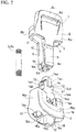
Fig. 1 is an exploded perspective view of a cord lock according to the first embodiment of the present invention; -
Fig. 2 is an exploded perspective view of the cord lock, and shows the cord lock viewed from a direction of differing fromFig. 1 ; -
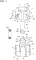
Fig. 3 is an exploded cross-sectional view of the cord lock; -
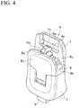
Fig. 4 is a perspective view of the cord lock; -
Fig. 5 is a perspective view of the cord lock, and shows the cord lock viewed from a direction of differing fromFig. 4 ; -
Fig. 6 is a front view of the cord lock; -
Fig. 7 is a side view of the cord lock; -
Fig. 8 is a side view wherein the cord lock is viewed from an upper side inFig. 6 ; -
Fig. 9 is a side view wherein the cord lock is viewed from a lower side inFig. 6 ; -
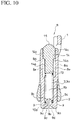
Fig. 10 is a cross-sectional view taken along an A-A line position inFig. 6 ; -
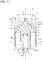
Fig. 11 is a cross-sectional view taken along a B-B line position inFig. 7 ; -
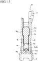
Fig. 12 is a cross-sectional view showing a state wherein a male member is operated to be maximally pulled out of an inside of a female member; -
Fig. 13 is a cross-sectional view showing a state inFig. 12 at a position of diffing by 90 degrees fromFig. 12 in cross section; -
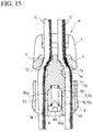
Fig. 14 is a cross-sectional view of the cord lock, and shows a state wherein the cord lock is fastened to a string; and -
Fig. 15 is a cross-sectional view showing a state inFig. 14 at a position of diffing by 90 degrees fromFig. 14 in cross section. - Hereinafter, a typical embodiment of the present invention will be explained with reference to
Fig. 1 to Fig. 15 . - A cord lock R according to the embodiment can be fastened to an arbitrary position of a string C, and is formed such that the aforementioned fastened state is releasable by a pulling operation which reduces an entering amount of one portion of a
male member 2 into afemale member 1. - Such string C may have any shape (a round string, a flat string, and the like), any material, or any structure (a knitted string, an elastic string, a string made of synthetic resin, and the like) provided that the cord lock R can be fastened in the aforementioned manner. Typically, such cord lock R is fastened to the string C in various types of articles provided with a portion which is narrowed or tightened by the aforementioned string C, and is used in such a way so as to narrow or loosen the aforementioned portion by changing a fastening position thereof.
- The
female member 1 comprises afirst opening 4, asecond opening 5, and aninsertion path 6 for the string C ranging therebetween. - On the other hand, the
male member 2 enters one portion thereof into theinsertion path 6 from the first opening 4 side, and comprises a male-side fastening portion 12 to be fastened to the string C inserted to pass through theinsertion path 6 in cooperation with a female-side fastening portion 7 formed inside theinsertion path 6 at the aforementioned one portion. - Also, a spring member 3 for storing energy by the pulling operation is interposed between the
female member 1 and themale member 2. In an illustrated example, such spring member 3 is a compression coil spring 3a for storing energy by the pulling operation. - Fastening relative to the string C is released by the pulling operation of reducing the entering amount of one portion of the
male member 2 into theinsertion path 6 relative to thefemale member 1 by gripping the string C pulled out of the first opening 4 side, and the pulling operation of reducing the entering amount of one portion of themale member 2 into theinsertion path 6 relative to themale member 2 by gripping the string C pulled out of the second opening 5 side. - In the embodiment, in the cord lock R, the string C passes through respective both sides sandwiching a moving center axis x (see
Fig. 11 ) of themale member 2. - In a state wherein the pulling operation is not carried out, the string C can be clamped by the female-
side fastening portion 7 and the male-side fastening potion 12 inside theinsertion path 6 by the spring member 3, thereby the cord lock R is fastened to the arbitrary position of the string C. - When the
female member 1 is operated to be pulled to an upper side inFig. 15 by gripping the string C pulled out of the first opening 4 side, the fastened state of the cord lock R relative to the string C is released, and the cord lock R moves to the upper side inFig. 15 as a whole, and when the pulling operation to the upper side halts, the cord lock R fastens to the string C again at a position after the movement. Also, when themale member 2 is operated to be pulled to a lower side inFig. 15 by gripping the string C pulled out of the second opening 5 side, the fastened state of the cord lock R relative to the string C is released, and the cord lock R moves to the lower side inFig. 15 as a whole, and when the pulling operation to the lower side halts, the cord lock R fastens to the string C again at a position after the movement. - The
female member 1 comprises a female-sidemain member portion 8 and a pair ofleg portions - The female-side
main member portion 8 is formed such that a cross-sectional shape in a direction orthogonal to the moving center axis x of themale member 2 has substantially a flat cylindrical shape. - Namely, the female-side
main member portion 8 comprises a pair ofwide face portions side face portions wide face portions - One cylinder end of the female-side
main member portion 8 functions as thefirst opening 4, and the other cylinder end of the female-sidemain member portion 8 functions as thesecond opening 5. - Inner faces of the thickness-
side face portions 8b of the female-sidemain member portion 8 incline in a direction of narrowing a width of an inside of the female-sidemain member portion 8 as advances to thesecond opening 5. In the illustrated example, on both sides sandwiching the moving center axis x, respectively, there are formed female-side fasteningportions 7 on the inner faces of the thickness-side face portions 8b. In the illustrated example, in each female-side fastening portion 7, there are alternately formed astep face 7a substantially parallel to the moving center line x, and astep 7b substantially orthogonal to the moving center line x, in a direction of the moving center line x, so that the female-side fastening portion 7 is provided on the inner face of the thickness-side face portion 8b. - Each
leg portion 9 has a band plate shape projecting from an edge portion forming thefirst opening 4 in the female-sidemain member portion 8 along the moving center axis x. One of the pair ofleg portions wide face portions leg portions wide face portions - A
housing space 10 for amain member portion 11 of the later-describedmale member 2 is made between such pair ofleg portions - Also, on an extending end side of the
leg portion 9, there is formed a projectingportion 9a projecting to thehousing space 10 side. In the illustrated example, at extending ends of the pair ofleg portions portions 9a. Between two projectingportions 9a, there is formed agap 9b. Also, in the two projectingportions 9a, there are respectively formedprojections 9c to enter into one spring end of the later-described spring member 3 on a side where the two projectingportions 9a face thefirst opening 4. The side where the two projectingportions 9a face thefirst opening 4, i.e., the side where the two projectingportions 9a face the later-describedsecond contact portion 13 of themale member 2 functions as afirst contact portion 10a for one spring end of the spring member 3. - In the illustrated example, a size in a direction along one moving center axis x of the pair of
wide face portions wide face portions wide face portions portion 8c from thesecond opening 5 for a difference between the aforementioned sizes. In the illustrated example, in the projectingportion 8c, there is formed along hole 8d in such a way so as to match a length direction along a direction orthogonal to the moving center axis x. In the illustrated example, a band-like member (not shown in the drawings) such as a tape and the like can pass through thelong hole 8d. - Also, in the illustrated example, in the pair of
wide face portions guide grooves 8e continuing to thefirst opening 4 side from thesecond opening 5 along the moving center axis x, and guidedportions 14c of the later-describedmain member portion 11 of themale member 2 are guided to theguide grooves 8e. - On the other hand, the
male member 2 includes themain member portion 11 provided with the male-side fastening portion 12, and thesecond contact portion 13 for the other spring end of the spring member 3 on a side opposite to a side where the male-side fastening portion 12 is formed. - The
main member portion 11 comprises asolid front portion 14 which becomes the one portion to enter into thefemale member 1; and aback portion 15 which substantially does not enter into the female-sidemain member portion 8 of thefemale member 1. - The
front portion 14 comprises width-side face portions 14a facing the inner faces of thewide face portions 8a of thefemale member 1; and side faceportions 14b facing the inner faces of the thickness-side face portions 8b of thefemale member 1. In two width-side face portions 14a of thefront portion 14, there are respectively formed the guidedportions 14c which can be housed in theguide grooves 8e of thefemale member 1. In the illustrated example, themain member portion 11 of themale member 2 is housed between the pair ofleg portions female member 1 while elastically deforming theleg portions 9, so that thefemale member 1 and themale member 2 are combined, and in a process of the combination, the guidedportions 14c can be housed in thecorresponding guide grooves 8e. Thereby, in the illustrated example, themale member 2 is combined with thefemale member 1 in a state wherein themain member portion 11 is disposed along the moving center axis x, and a string C can pass through respectively right and left of themain member portion 11. - In two
side face portions 14b of thefront portion 14, respectively, there are formedclaw portions 14d which become the male-side fastening portions 12. Twoclaw portions 14d are formed at an interval between theadjacent claw portions 14d in a direction along the moving center axis x. - A connecting end to the
back portion 15 in thefront portion 14 is a face orthogonal to the moving center axis x, and the aforementioned face functions as thesecond contact portion 13 for the other spring end of the spring member 3. - The
back portion 15 is formed by a pair ofwall portions wall portions side face portions 14b of thefront portion 14, and the other of the pair ofwall portions side face portions 14b of thefront portion 14. Also, thesecond contact portion 13 is positioned between the pair ofwall portions wall portions - Namely, in the embodiment, the
male member 2 comprises themain member portion 11 provided with thesecond contact portion 13 on the side opposite to the side where the male-side fastening portion 12 is formed, and thefemale member 1 comprises the pair ofleg portions first opening 4, and making thehousing space 10 for themain member portion 11 between the leg portions. On the extending end side of eachleg portion 9, there is formed the projectingportion 9a projecting to thehousing space 10 side, and themain member portion 11 can be housed in thehousing space 10 such that the projectingportion 9a faces thesecond contact portion 13 by elastically deforming theleg portion 9. Also, the side where the projectingportion 9a faces thesecond contact portion 13 becomes thefirst contact portion 10a. - Also, in a state wherein the
male member 2 and thefemale member 1 are combined, there is formed ahousing portion 19 for the spring member 3 in cooperation with the pair ofwall portions main member portion 11, thesecond contact portion 13, and the pair ofleg portions - Specifically, the
front portion 14 of themain member portion 11 which becomes the one portion of themale member 2 can be inserted into thefemale member 1 while elastically deforming theleg portion 9 in a direction of widening a distance between the pair ofleg portions female member 1. In the illustrated example, at the extending end of theleg portion 9 of thefemale member 1, there is formed a guidedface 9d contacting aguide face 14e formed in the guidedportion 14c in a front end of thefront portion 14 of themain member portion 11 of themale member 2 to promote elastic deformation in the aforementioned direction of theleg portion 9. - When the
front portion 14 of themain member portion 11 of themale member 2 is inserted to a position where the projectingportion 9a which becomes thefirst contact portion 10a is positioned behind thesecond contact portion 13 thereof, the pair ofleg portions first contact portion 10a and thesecond contact portion 13 face each other, and themale member 2 and thefemale member 1 are combined in a state wherein themale member 2 and thefemale member 1 do not separate, and there is formed thehousing portion 19. - In the embodiment, the
first contact portion 10a for one spring end of the spring member 3 is integrally formed with thefemale member 1, and thesecond contact portion 13 for the other spring end of the spring member 3 is integrally formed with themale member 2. Thereby, the cord lock according to the embodiment can be appropriately formed by three parts of themale member 2, thefemale member 1, and the spring member 3. - In the illustrated example, the
male member 2 includes ahead portion 16 wherein a cross-sectional shape thereof in a direction orthogonal to the moving center axis x has substantially a flat cylindrical shape. Namely, thehead portion 16 comprises a pair ofwide face portions side face portions wide face portions male member 2 and thefemale member 1, thewide face portions 16a of thehead portion 16 are positioned on a side same as thewide face portions 8a of thefemale member 1, and the thickness-side face portions 16b of thehead portion 16 are positioned on a side same as the thickness-side face portions 8b of thefemale member 1. Thehead portion 16 comprises athird opening 16c facing thefirst opening 4 of thefemale member 1, and afourth opening 16d on a side opposite to thethird opening 16c. Then, thehead portion 16 and themain member portion 11 are integrated in such a way so as to project thefront portion 14 of themain member portion 11 from thethird opening 16c of thehead portion 16. Specifically, thewall portion 15a forming theback portion 15 is integrated with thewide face portion 16a of thehead portion 16, and in the combined state of themale member 2 and thefemale member 1, theleg portion 9 of thefemale member 1 enters into thehead portion 16 by passing between the pair ofwall portions male member 2, respectively, there is formed an insertion path for the string C between the thickness-side face portion 16b of thehead portion 16 and thewall portion 15a of theback portion 15. Specifically, in thewall portion 15a, oneedge portion 15b along a continuous direction thereof is integrated with one inner face of the pair ofwide face portions head portion 16, and theother edge portion 15b along the continuous direction thereof is integrated with the other inner face of the pair ofwide face portions head portion 16, respectively (Fig. 2 ). - Incidentally, in the illustrated example, in the
wide face portion 16a of thehead portion 16, there is formed anotch portion 16e opening outwardly on thefirst opening 4 side between a position of an approximately middle in the direction of the moving center axis x and thefirst opening 4, and thenotch portion 16e communicates with a space between the pair ofwall portions back portion 15 of the main member portion 11 (Fig. 1 ). - Also, in the present embodiment, there is formed a
communication portion 18 for introducing the spring member 3 to thehousing portion 19 using theinsertion path 17 between theinsertion path 17 and thehousing portion 19. - In the illustrated example, although one of the pair of
wall portions third opening 16c and thefourth opening 16d of thehead portion 16, the other of the pair ofwall portions wall portions communication portion 18 between a terminal facing afourth opening 16d side of the other of thewall portions 15a and thefourth opening 16d. - Thereby, in the present embodiment, from the state wherein the
male member 2 and thefemale member 1 are combined, the spring member 3 is housed in thehousing portion 19 using theinsertion path 17 and thecommunication portion 18 so as to create a state of operating an urging force in a direction of clamping the string C between the male-side fastening portion 12 and the female-side fastening portion 7 after themale member 2 and thefemale member 1 are combined. - Typically, on both sides sandwiching the moving center axis x, respectively, the string C pulled out of the
first opening 4 through theinsertion path 6 from thesecond opening 5 of thefemale member 1 is passed through theinsertion path 17 of themale member 2. From that state, thefront portion 14 of themain member portion 11 of themale member 2 is led into the female-sidemain member portion 8 by passing between the pair ofleg portions female member 1 and through thefirst opening 4 so as to combine themale member 2 and thefemale member 1. After that, the spring member 3 is housed in thehousing portion 19 using theinsertions path 17 and thecommunication portion 18, so that in a state wherein the string C is passed through respectively the right and left of the moving center axis x, themale member 2 and thefemale member 1 can be integrated, and the spring member 3 can be incorporated in such a way so as to store energy by the pulling operation. In a state wherein the pulling operation is not carried out, the entering amount of thefront portion 14 of themain member portion 11 as one portion of themale member 2 into the female-sidemain member portion 8 as theinsertion path 6 of thefemale member 1 is maximized, and the string C passing through in the aforementioned manner is clamped between the male-side fastening portion 12 and the female-side fastening portion 7, so that the cord lock is fastened to an arbitrary position of the string C. - When the aforementioned pulling operation is carried out, while compressing the compression coil spring 3a as the spring member 3 and storing energy, the entering amount of the
front portion 14 of themain member portion 11 as one portion of themale member 2 into the female-sidemain member portion 8 of thefemale member 1 as theinsertion path 6 is reduced, and a distance between the male-side fastening portion 12 and the female-side fastening portion 7 widens so as to loosen the tightening of the string C between the male-side fastening portion 12 and the female-side fastening portion 7, and to release the fastening of the cord lock R relative to the string C. - The
male member 2 and thefemale member 1 are typically formed by plastic. In such a case, an elastic deformation characteristic as described above can be easily and appropriately provided to the pair ofleg portions female member 1. - Incidentally, naturally, the present invention is not limited to the embodiment explained hereinabove, and includes all embodiments which can obtain the object of the present invention.
- The disclosure of Japanese Patent Application No.
2017-173696, filed on September 11, 2017 - While the invention has been explained with reference to the specific embodiments of the invention, the explanation is illustrative and the invention is limited only by the appended claims.
Claims (4)
- A cord lock, comprising:a female member having a first opening, a second opening, an insertion path for a string therebetween, and female-side fastening portions formed in the insertion path;a male member having one portion entering into the insertion path from a side of the first opening, and male-side fastening portions at the one portion adapted to be fastened to the string inserted to pass through the insertion path in cooperation with the female-side fastening portions; anda spring member interposed between the female member and the male member,wherein fastening relative to the string is released by a pulling operation of reducing an entering amount of the one portion of the male member into the insertion path, the spring member storing energy by the pulling operation, anda first contact portion of one spring end of the spring member is integrally formed with the female member, and a second contact portion of another spring end of the spring member is integrally formed with the male member.
- A cord lock according to claim 1, wherein the male member includes a main member portion having the second contact portion on a side opposite to a side where the male-side fastening portions are formed,
the female member includes a pair of leg portions extending from the first opening to form a housing space for the main member portion between the leg portions, and projecting portions each projecting to the housing space at an extending end of each leg portion,
the main member portion is housed in the housing space in such a way to face the projecting portions to the second contact portion by elastically deforming the pair of leg portions, and
a side facing the second contact portion in the projecting portion becomes the first contact portion. - A cord lock according to claim 2, wherein the main member portion includes a pair of wall portions forming a housing portion for the spring member in cooperation with the second contact portion and the pair of leg portions.
- A cord lock according to claim 3, wherein the male member includes insertion paths for strings at sides of the main member portion, and forms a communication portion between the insertion path and the housing portion, for introducing the spring member to the housing portion using the insertion paths.
Applications Claiming Priority (1)
| Application Number | Priority Date | Filing Date | Title |
|---|---|---|---|
| JP2017173696A JP6873873B2 (en) | 2017-09-11 | 2017-09-11 | Code lock |
Publications (2)
| Publication Number | Publication Date |
|---|---|
| EP3453913A1 true EP3453913A1 (en) | 2019-03-13 |
| EP3453913B1 EP3453913B1 (en) | 2020-02-26 |
Family
ID=63556195
Family Applications (1)
| Application Number | Title | Priority Date | Filing Date |
|---|---|---|---|
| EP18193415.9A Active EP3453913B1 (en) | 2017-09-11 | 2018-09-10 | Cord lock |
Country Status (4)
| Country | Link |
|---|---|
| US (1) | US10508713B2 (en) |
| EP (1) | EP3453913B1 (en) |
| JP (1) | JP6873873B2 (en) |
| CN (1) | CN109488728B (en) |
Families Citing this family (20)
| Publication number | Priority date | Publication date | Assignee | Title |
|---|---|---|---|---|
| DE102016106958A1 (en) * | 2016-04-14 | 2017-10-19 | NITRO Snowboards Entwicklungs-GmbH | Lace protection for liner |
| TWI629018B (en) * | 2016-05-19 | 2018-07-11 | 仁不古股份有限公司 | Cord lock |
| US10527129B2 (en) | 2016-08-26 | 2020-01-07 | Nike, Inc. | Cord lock |
| USD938953S1 (en) * | 2018-08-28 | 2021-12-21 | New Concept Development Corporation | Peripheral cord lock |
| US20200248781A1 (en) * | 2019-02-01 | 2020-08-06 | Craig W. Patterson | Cinching device |
| CN113645872B (en) * | 2019-04-02 | 2024-06-25 | 株式会社利富高 | Rope Fasteners |
| US11320024B2 (en) * | 2019-06-26 | 2022-05-03 | Nite Ize, Inc. | Systems and methods for a rope, flat-strap, and bungee securing device |
| US10982731B2 (en) * | 2019-09-06 | 2021-04-20 | Innovative Product Solutions, LLC | Bungee loop retention assemblies |
| JP7186151B2 (en) * | 2019-09-11 | 2022-12-08 | 株式会社ニフコ | code lock |
| JP7529491B2 (en) * | 2019-09-19 | 2024-08-06 | Ykk株式会社 | Cord stopper |
| WO2021067723A1 (en) * | 2019-10-03 | 2021-04-08 | Nike Innovate C.V. | Dynamic lacing system |
| US11585408B2 (en) * | 2019-10-23 | 2023-02-21 | Sewn Products, Llc | Cord tightening and retaining device |
| KR102176243B1 (en) * | 2020-04-22 | 2020-11-09 | 이동훈 | Shoelace loosening prevention device |
| JP7502569B2 (en) * | 2021-08-10 | 2024-06-18 | Ykk株式会社 | Cord stopper |
| USD1045580S1 (en) * | 2022-05-18 | 2024-10-08 | 9150-9893 Québec Inc. | Thimble for rope winch |
| CN117770583B (en) * | 2022-09-20 | 2026-05-05 | 台湾扣具工业股份有限公司 | Rope end buckles and their male buckles |
| CN115813090B (en) * | 2022-12-15 | 2025-07-25 | 深圳市联星服装辅料有限公司 | Sliding rope fastener |
| US20240343494A1 (en) * | 2023-04-11 | 2024-10-17 | Motion Industries, Inc. | Strip belt for a merge conveyor |
| US12433372B2 (en) * | 2023-06-23 | 2025-10-07 | U-Lace, Llc | Apparatus, system, and method for locking laces |
| WO2025220165A1 (en) * | 2024-04-17 | 2025-10-23 | Ykk株式会社 | Cord stopper |
Citations (5)
| Publication number | Priority date | Publication date | Assignee | Title |
|---|---|---|---|---|
| US3007220A (en) * | 1959-01-26 | 1961-11-07 | Hartford Company | Self-applying releasable cord fastener |
| US5894639A (en) * | 1998-03-19 | 1999-04-20 | Robert O. Boden | Cord lock apparatus |
| FR2792506A1 (en) * | 1999-04-21 | 2000-10-27 | Lafuma Sa | LOCKING DEVICE FOR CLOSING ARTICLES SUCH AS SHOES, BAGS, CLOTHING |
| JP2005000231A (en) | 2003-06-09 | 2005-01-06 | Aprica Kassai Inc | String clasp and baby carriage |
| EP2607747A2 (en) * | 2011-12-20 | 2013-06-26 | Nifco Taiwan Corporation | Cord lock |
Family Cites Families (10)
| Publication number | Priority date | Publication date | Assignee | Title |
|---|---|---|---|---|
| US307806A (en) * | 1884-11-11 | Cord or strap fastener | ||
| US2200895A (en) * | 1939-09-13 | 1940-05-14 | Clarence J Rio | Shoestring fastener |
| US4156574A (en) * | 1978-02-06 | 1979-05-29 | Boden Ogden W | Cord lock with self locking spring feelers |
| JPH026809Y2 (en) * | 1986-01-27 | 1990-02-19 | ||
| US4878269A (en) * | 1986-09-10 | 1989-11-07 | National Molding Corp. | Cord fastener |
| US5572770A (en) * | 1995-08-18 | 1996-11-12 | Boden; Robert O. | Self locking cord lock |
| US6457214B1 (en) * | 2000-10-13 | 2002-10-01 | Robert O. Boden | Tamper-resistant cord lock apparatus |
| JP2005118430A (en) * | 2003-10-20 | 2005-05-12 | Combi Corp | Cord lock for shoelace |
| JP2013039176A (en) * | 2011-08-12 | 2013-02-28 | Nifco Inc | Cord lock |
| FR3021083B1 (en) * | 2014-05-16 | 2016-06-24 | Zedel | BLOCKING DEVICE FOR WIRED ELEMENT |
-
2017
- 2017-09-11 JP JP2017173696A patent/JP6873873B2/en active Active
-
2018
- 2018-09-06 US US16/123,497 patent/US10508713B2/en active Active
- 2018-09-07 CN CN201811041076.3A patent/CN109488728B/en active Active
- 2018-09-10 EP EP18193415.9A patent/EP3453913B1/en active Active
Patent Citations (5)
| Publication number | Priority date | Publication date | Assignee | Title |
|---|---|---|---|---|
| US3007220A (en) * | 1959-01-26 | 1961-11-07 | Hartford Company | Self-applying releasable cord fastener |
| US5894639A (en) * | 1998-03-19 | 1999-04-20 | Robert O. Boden | Cord lock apparatus |
| FR2792506A1 (en) * | 1999-04-21 | 2000-10-27 | Lafuma Sa | LOCKING DEVICE FOR CLOSING ARTICLES SUCH AS SHOES, BAGS, CLOTHING |
| JP2005000231A (en) | 2003-06-09 | 2005-01-06 | Aprica Kassai Inc | String clasp and baby carriage |
| EP2607747A2 (en) * | 2011-12-20 | 2013-06-26 | Nifco Taiwan Corporation | Cord lock |
Also Published As
| Publication number | Publication date |
|---|---|
| EP3453913B1 (en) | 2020-02-26 |
| US20190078646A1 (en) | 2019-03-14 |
| JP2019047949A (en) | 2019-03-28 |
| CN109488728A (en) | 2019-03-19 |
| US10508713B2 (en) | 2019-12-17 |
| CN109488728B (en) | 2020-10-02 |
| JP6873873B2 (en) | 2021-05-19 |
Similar Documents
| Publication | Publication Date | Title |
|---|---|---|
| EP3453913B1 (en) | Cord lock | |
| US10718404B2 (en) | Cord lock | |
| KR100713768B1 (en) | String holder | |
| US7979966B2 (en) | Buckle | |
| JP3394849B2 (en) | Tethers | |
| US6061883A (en) | Buckle | |
| US10063007B2 (en) | Wire cover | |
| JP6266226B2 (en) | Lockable buckle | |
| JP7186151B2 (en) | code lock | |
| US11199244B2 (en) | String stopper | |
| US11039666B2 (en) | Plug for buckle, and buckle | |
| US10588383B2 (en) | Buckle | |
| JP6659468B2 (en) | Code lock | |
| US9721704B2 (en) | Wire cover | |
| US20100284761A1 (en) | Press Type Fastener | |
| US20050227528A1 (en) | Cord end cover | |
| US10711813B2 (en) | Attachment device providing double engagement for high retention | |
| CN217743333U (en) | Shoelace fastening device | |
| US10125845B2 (en) | Cord Lock | |
| KR19980024729A (en) | Electrical connector coupler | |
| US6056565A (en) | Low insertion force sliding cam electrical connector | |
| US6712521B1 (en) | Optical connector enabling multicore structure by efficiently utilizing space | |
| CN219628959U (en) | Side pressure same-mould rope fastener | |
| CN218267025U (en) | Rope buckle convenient to assemble | |
| CN112401413B (en) | Belt buckle with wire adjusting part |
Legal Events
| Date | Code | Title | Description |
|---|---|---|---|
| PUAI | Public reference made under article 153(3) epc to a published international application that has entered the european phase |
Free format text: ORIGINAL CODE: 0009012 |
|
| STAA | Information on the status of an ep patent application or granted ep patent |
Free format text: STATUS: REQUEST FOR EXAMINATION WAS MADE |
|
| 17P | Request for examination filed |
Effective date: 20180910 |
|
| AK | Designated contracting states |
Kind code of ref document: A1 Designated state(s): AL AT BE BG CH CY CZ DE DK EE ES FI FR GB GR HR HU IE IS IT LI LT LU LV MC MK MT NL NO PL PT RO RS SE SI SK SM TR |
|
| AX | Request for extension of the european patent |
Extension state: BA ME |
|
| GRAP | Despatch of communication of intention to grant a patent |
Free format text: ORIGINAL CODE: EPIDOSNIGR1 |
|
| STAA | Information on the status of an ep patent application or granted ep patent |
Free format text: STATUS: GRANT OF PATENT IS INTENDED |
|
| INTG | Intention to grant announced |
Effective date: 20191002 |
|
| GRAS | Grant fee paid |
Free format text: ORIGINAL CODE: EPIDOSNIGR3 |
|
| GRAA | (expected) grant |
Free format text: ORIGINAL CODE: 0009210 |
|
| STAA | Information on the status of an ep patent application or granted ep patent |
Free format text: STATUS: THE PATENT HAS BEEN GRANTED |
|
| AK | Designated contracting states |
Kind code of ref document: B1 Designated state(s): AL AT BE BG CH CY CZ DE DK EE ES FI FR GB GR HR HU IE IS IT LI LT LU LV MC MK MT NL NO PL PT RO RS SE SI SK SM TR |
|
| REG | Reference to a national code |
Ref country code: GB Ref legal event code: FG4D |
|
| REG | Reference to a national code |
Ref country code: CH Ref legal event code: EP |
|
| REG | Reference to a national code |
Ref country code: DE Ref legal event code: R096 Ref document number: 602018002693 Country of ref document: DE |
|
| REG | Reference to a national code |
Ref country code: AT Ref legal event code: REF Ref document number: 1238008 Country of ref document: AT Kind code of ref document: T Effective date: 20200315 |
|
| REG | Reference to a national code |
Ref country code: IE Ref legal event code: FG4D |
|
| PG25 | Lapsed in a contracting state [announced via postgrant information from national office to epo] |
Ref country code: RS Free format text: LAPSE BECAUSE OF FAILURE TO SUBMIT A TRANSLATION OF THE DESCRIPTION OR TO PAY THE FEE WITHIN THE PRESCRIBED TIME-LIMIT Effective date: 20200226 Ref country code: FI Free format text: LAPSE BECAUSE OF FAILURE TO SUBMIT A TRANSLATION OF THE DESCRIPTION OR TO PAY THE FEE WITHIN THE PRESCRIBED TIME-LIMIT Effective date: 20200226 Ref country code: NO Free format text: LAPSE BECAUSE OF FAILURE TO SUBMIT A TRANSLATION OF THE DESCRIPTION OR TO PAY THE FEE WITHIN THE PRESCRIBED TIME-LIMIT Effective date: 20200526 |
|
| REG | Reference to a national code |
Ref country code: NL Ref legal event code: MP Effective date: 20200226 |
|
| REG | Reference to a national code |
Ref country code: LT Ref legal event code: MG4D |
|
| PG25 | Lapsed in a contracting state [announced via postgrant information from national office to epo] |
Ref country code: SE Free format text: LAPSE BECAUSE OF FAILURE TO SUBMIT A TRANSLATION OF THE DESCRIPTION OR TO PAY THE FEE WITHIN THE PRESCRIBED TIME-LIMIT Effective date: 20200226 Ref country code: LV Free format text: LAPSE BECAUSE OF FAILURE TO SUBMIT A TRANSLATION OF THE DESCRIPTION OR TO PAY THE FEE WITHIN THE PRESCRIBED TIME-LIMIT Effective date: 20200226 Ref country code: HR Free format text: LAPSE BECAUSE OF FAILURE TO SUBMIT A TRANSLATION OF THE DESCRIPTION OR TO PAY THE FEE WITHIN THE PRESCRIBED TIME-LIMIT Effective date: 20200226 Ref country code: BG Free format text: LAPSE BECAUSE OF FAILURE TO SUBMIT A TRANSLATION OF THE DESCRIPTION OR TO PAY THE FEE WITHIN THE PRESCRIBED TIME-LIMIT Effective date: 20200526 Ref country code: IS Free format text: LAPSE BECAUSE OF FAILURE TO SUBMIT A TRANSLATION OF THE DESCRIPTION OR TO PAY THE FEE WITHIN THE PRESCRIBED TIME-LIMIT Effective date: 20200626 Ref country code: GR Free format text: LAPSE BECAUSE OF FAILURE TO SUBMIT A TRANSLATION OF THE DESCRIPTION OR TO PAY THE FEE WITHIN THE PRESCRIBED TIME-LIMIT Effective date: 20200527 |
|
| PG25 | Lapsed in a contracting state [announced via postgrant information from national office to epo] |
Ref country code: NL Free format text: LAPSE BECAUSE OF FAILURE TO SUBMIT A TRANSLATION OF THE DESCRIPTION OR TO PAY THE FEE WITHIN THE PRESCRIBED TIME-LIMIT Effective date: 20200226 |
|
| PG25 | Lapsed in a contracting state [announced via postgrant information from national office to epo] |
Ref country code: SK Free format text: LAPSE BECAUSE OF FAILURE TO SUBMIT A TRANSLATION OF THE DESCRIPTION OR TO PAY THE FEE WITHIN THE PRESCRIBED TIME-LIMIT Effective date: 20200226 Ref country code: RO Free format text: LAPSE BECAUSE OF FAILURE TO SUBMIT A TRANSLATION OF THE DESCRIPTION OR TO PAY THE FEE WITHIN THE PRESCRIBED TIME-LIMIT Effective date: 20200226 Ref country code: CZ Free format text: LAPSE BECAUSE OF FAILURE TO SUBMIT A TRANSLATION OF THE DESCRIPTION OR TO PAY THE FEE WITHIN THE PRESCRIBED TIME-LIMIT Effective date: 20200226 Ref country code: PT Free format text: LAPSE BECAUSE OF FAILURE TO SUBMIT A TRANSLATION OF THE DESCRIPTION OR TO PAY THE FEE WITHIN THE PRESCRIBED TIME-LIMIT Effective date: 20200719 Ref country code: DK Free format text: LAPSE BECAUSE OF FAILURE TO SUBMIT A TRANSLATION OF THE DESCRIPTION OR TO PAY THE FEE WITHIN THE PRESCRIBED TIME-LIMIT Effective date: 20200226 Ref country code: LT Free format text: LAPSE BECAUSE OF FAILURE TO SUBMIT A TRANSLATION OF THE DESCRIPTION OR TO PAY THE FEE WITHIN THE PRESCRIBED TIME-LIMIT Effective date: 20200226 Ref country code: ES Free format text: LAPSE BECAUSE OF FAILURE TO SUBMIT A TRANSLATION OF THE DESCRIPTION OR TO PAY THE FEE WITHIN THE PRESCRIBED TIME-LIMIT Effective date: 20200226 Ref country code: EE Free format text: LAPSE BECAUSE OF FAILURE TO SUBMIT A TRANSLATION OF THE DESCRIPTION OR TO PAY THE FEE WITHIN THE PRESCRIBED TIME-LIMIT Effective date: 20200226 Ref country code: SM Free format text: LAPSE BECAUSE OF FAILURE TO SUBMIT A TRANSLATION OF THE DESCRIPTION OR TO PAY THE FEE WITHIN THE PRESCRIBED TIME-LIMIT Effective date: 20200226 |
|
| REG | Reference to a national code |
Ref country code: AT Ref legal event code: MK05 Ref document number: 1238008 Country of ref document: AT Kind code of ref document: T Effective date: 20200226 |
|
| REG | Reference to a national code |
Ref country code: DE Ref legal event code: R097 Ref document number: 602018002693 Country of ref document: DE |
|
| PLBE | No opposition filed within time limit |
Free format text: ORIGINAL CODE: 0009261 |
|
| STAA | Information on the status of an ep patent application or granted ep patent |
Free format text: STATUS: NO OPPOSITION FILED WITHIN TIME LIMIT |
|
| PG25 | Lapsed in a contracting state [announced via postgrant information from national office to epo] |
Ref country code: AT Free format text: LAPSE BECAUSE OF FAILURE TO SUBMIT A TRANSLATION OF THE DESCRIPTION OR TO PAY THE FEE WITHIN THE PRESCRIBED TIME-LIMIT Effective date: 20200226 Ref country code: IT Free format text: LAPSE BECAUSE OF FAILURE TO SUBMIT A TRANSLATION OF THE DESCRIPTION OR TO PAY THE FEE WITHIN THE PRESCRIBED TIME-LIMIT Effective date: 20200226 |
|
| 26N | No opposition filed |
Effective date: 20201127 |
|
| PG25 | Lapsed in a contracting state [announced via postgrant information from national office to epo] |
Ref country code: SI Free format text: LAPSE BECAUSE OF FAILURE TO SUBMIT A TRANSLATION OF THE DESCRIPTION OR TO PAY THE FEE WITHIN THE PRESCRIBED TIME-LIMIT Effective date: 20200226 Ref country code: PL Free format text: LAPSE BECAUSE OF FAILURE TO SUBMIT A TRANSLATION OF THE DESCRIPTION OR TO PAY THE FEE WITHIN THE PRESCRIBED TIME-LIMIT Effective date: 20200226 |
|
| REG | Reference to a national code |
Ref country code: BE Ref legal event code: MM Effective date: 20200930 |
|
| PG25 | Lapsed in a contracting state [announced via postgrant information from national office to epo] |
Ref country code: LU Free format text: LAPSE BECAUSE OF NON-PAYMENT OF DUE FEES Effective date: 20200910 |
|
| PG25 | Lapsed in a contracting state [announced via postgrant information from national office to epo] |
Ref country code: IE Free format text: LAPSE BECAUSE OF NON-PAYMENT OF DUE FEES Effective date: 20200910 Ref country code: BE Free format text: LAPSE BECAUSE OF NON-PAYMENT OF DUE FEES Effective date: 20200930 |
|
| REG | Reference to a national code |
Ref country code: CH Ref legal event code: PL |
|
| PG25 | Lapsed in a contracting state [announced via postgrant information from national office to epo] |
Ref country code: TR Free format text: LAPSE BECAUSE OF FAILURE TO SUBMIT A TRANSLATION OF THE DESCRIPTION OR TO PAY THE FEE WITHIN THE PRESCRIBED TIME-LIMIT Effective date: 20200226 Ref country code: MT Free format text: LAPSE BECAUSE OF FAILURE TO SUBMIT A TRANSLATION OF THE DESCRIPTION OR TO PAY THE FEE WITHIN THE PRESCRIBED TIME-LIMIT Effective date: 20200226 Ref country code: CY Free format text: LAPSE BECAUSE OF FAILURE TO SUBMIT A TRANSLATION OF THE DESCRIPTION OR TO PAY THE FEE WITHIN THE PRESCRIBED TIME-LIMIT Effective date: 20200226 |
|
| PG25 | Lapsed in a contracting state [announced via postgrant information from national office to epo] |
Ref country code: MK Free format text: LAPSE BECAUSE OF FAILURE TO SUBMIT A TRANSLATION OF THE DESCRIPTION OR TO PAY THE FEE WITHIN THE PRESCRIBED TIME-LIMIT Effective date: 20200226 Ref country code: MC Free format text: LAPSE BECAUSE OF FAILURE TO SUBMIT A TRANSLATION OF THE DESCRIPTION OR TO PAY THE FEE WITHIN THE PRESCRIBED TIME-LIMIT Effective date: 20200226 Ref country code: AL Free format text: LAPSE BECAUSE OF FAILURE TO SUBMIT A TRANSLATION OF THE DESCRIPTION OR TO PAY THE FEE WITHIN THE PRESCRIBED TIME-LIMIT Effective date: 20200226 |
|
| PG25 | Lapsed in a contracting state [announced via postgrant information from national office to epo] |
Ref country code: LI Free format text: LAPSE BECAUSE OF NON-PAYMENT OF DUE FEES Effective date: 20210930 Ref country code: CH Free format text: LAPSE BECAUSE OF NON-PAYMENT OF DUE FEES Effective date: 20210930 |
|
| GBPC | Gb: european patent ceased through non-payment of renewal fee |
Effective date: 20220910 |
|
| PG25 | Lapsed in a contracting state [announced via postgrant information from national office to epo] |
Ref country code: GB Free format text: LAPSE BECAUSE OF NON-PAYMENT OF DUE FEES Effective date: 20220910 |
|
| PGFP | Annual fee paid to national office [announced via postgrant information from national office to epo] |
Ref country code: DE Payment date: 20250730 Year of fee payment: 8 |
|
| PGFP | Annual fee paid to national office [announced via postgrant information from national office to epo] |
Ref country code: FR Payment date: 20250808 Year of fee payment: 8 |