EP3453897A1 - Display mounting apparatus - Google Patents
Display mounting apparatus Download PDFInfo
- Publication number
- EP3453897A1 EP3453897A1 EP18182912.8A EP18182912A EP3453897A1 EP 3453897 A1 EP3453897 A1 EP 3453897A1 EP 18182912 A EP18182912 A EP 18182912A EP 3453897 A1 EP3453897 A1 EP 3453897A1
- Authority
- EP
- European Patent Office
- Prior art keywords
- display module
- mounting apparatus
- display
- engagement
- module
- Prior art date
- Legal status (The legal status is an assumption and is not a legal conclusion. Google has not performed a legal analysis and makes no representation as to the accuracy of the status listed.)
- Granted
Links
Images




Classifications
-
- F—MECHANICAL ENGINEERING; LIGHTING; HEATING; WEAPONS; BLASTING
- F16—ENGINEERING ELEMENTS AND UNITS; GENERAL MEASURES FOR PRODUCING AND MAINTAINING EFFECTIVE FUNCTIONING OF MACHINES OR INSTALLATIONS; THERMAL INSULATION IN GENERAL
- F16M—FRAMES, CASINGS OR BEDS OF ENGINES, MACHINES OR APPARATUS, NOT SPECIFIC TO ENGINES, MACHINES OR APPARATUS PROVIDED FOR ELSEWHERE; STANDS; SUPPORTS
- F16M11/00—Stands or trestles as supports for apparatus or articles placed thereon ; Stands for scientific apparatus such as gravitational force meters
- F16M11/02—Heads
- F16M11/04—Means for attachment of apparatus; Means allowing adjustment of the apparatus relatively to the stand
- F16M11/041—Allowing quick release of the apparatus
-
- A—HUMAN NECESSITIES
- A47—FURNITURE; DOMESTIC ARTICLES OR APPLIANCES; COFFEE MILLS; SPICE MILLS; SUCTION CLEANERS IN GENERAL
- A47F—SPECIAL FURNITURE, FITTINGS, OR ACCESSORIES FOR SHOPS, STOREHOUSES, BARS, RESTAURANTS OR THE LIKE; PAYING COUNTERS
- A47F5/00—Show stands, hangers, or shelves characterised by their constructional features
- A47F5/08—Show stands, hangers, or shelves characterised by their constructional features secured to the wall, ceiling, or the like; Wall-bracket display devices
- A47F5/0807—Display panels, grids or rods used for suspending merchandise or cards supporting articles; Movable brackets therefor
-
- A—HUMAN NECESSITIES
- A47—FURNITURE; DOMESTIC ARTICLES OR APPLIANCES; COFFEE MILLS; SPICE MILLS; SUCTION CLEANERS IN GENERAL
- A47F—SPECIAL FURNITURE, FITTINGS, OR ACCESSORIES FOR SHOPS, STOREHOUSES, BARS, RESTAURANTS OR THE LIKE; PAYING COUNTERS
- A47F5/00—Show stands, hangers, or shelves characterised by their constructional features
- A47F5/08—Show stands, hangers, or shelves characterised by their constructional features secured to the wall, ceiling, or the like; Wall-bracket display devices
- A47F5/0876—Display stands with fixed brackets or hooks for suspending articles
-
- B—PERFORMING OPERATIONS; TRANSPORTING
- B25—HAND TOOLS; PORTABLE POWER-DRIVEN TOOLS; MANIPULATORS
- B25B—TOOLS OR BENCH DEVICES NOT OTHERWISE PROVIDED FOR, FOR FASTENING, CONNECTING, DISENGAGING, OR HOLDING
- B25B23/00—Details of, or accessories for, spanners, wrenches, screwdrivers
- B25B23/02—Arrangements for handling screws or nuts
- B25B23/08—Arrangements for handling screws or nuts for holding or positioning screw or nut prior to or during its rotation
- B25B23/12—Arrangements for handling screws or nuts for holding or positioning screw or nut prior to or during its rotation using magnetic means
-
- F—MECHANICAL ENGINEERING; LIGHTING; HEATING; WEAPONS; BLASTING
- F16—ENGINEERING ELEMENTS AND UNITS; GENERAL MEASURES FOR PRODUCING AND MAINTAINING EFFECTIVE FUNCTIONING OF MACHINES OR INSTALLATIONS; THERMAL INSULATION IN GENERAL
- F16B—DEVICES FOR FASTENING OR SECURING CONSTRUCTIONAL ELEMENTS OR MACHINE PARTS TOGETHER, e.g. NAILS, BOLTS, CIRCLIPS, CLAMPS, CLIPS OR WEDGES; JOINTS OR JOINTING
- F16B1/00—Devices for securing together, or preventing relative movement between, constructional elements or machine parts
-
- F—MECHANICAL ENGINEERING; LIGHTING; HEATING; WEAPONS; BLASTING
- F16—ENGINEERING ELEMENTS AND UNITS; GENERAL MEASURES FOR PRODUCING AND MAINTAINING EFFECTIVE FUNCTIONING OF MACHINES OR INSTALLATIONS; THERMAL INSULATION IN GENERAL
- F16B—DEVICES FOR FASTENING OR SECURING CONSTRUCTIONAL ELEMENTS OR MACHINE PARTS TOGETHER, e.g. NAILS, BOLTS, CIRCLIPS, CLAMPS, CLIPS OR WEDGES; JOINTS OR JOINTING
- F16B23/00—Specially shaped nuts or heads of bolts or screws for rotations by a tool
-
- F—MECHANICAL ENGINEERING; LIGHTING; HEATING; WEAPONS; BLASTING
- F16—ENGINEERING ELEMENTS AND UNITS; GENERAL MEASURES FOR PRODUCING AND MAINTAINING EFFECTIVE FUNCTIONING OF MACHINES OR INSTALLATIONS; THERMAL INSULATION IN GENERAL
- F16B—DEVICES FOR FASTENING OR SECURING CONSTRUCTIONAL ELEMENTS OR MACHINE PARTS TOGETHER, e.g. NAILS, BOLTS, CIRCLIPS, CLAMPS, CLIPS OR WEDGES; JOINTS OR JOINTING
- F16B5/00—Joining sheets or plates, e.g. panels, to one another or to strips or bars parallel to them
- F16B5/02—Joining sheets or plates, e.g. panels, to one another or to strips or bars parallel to them by means of fastening members using screw-thread
-
- F—MECHANICAL ENGINEERING; LIGHTING; HEATING; WEAPONS; BLASTING
- F16—ENGINEERING ELEMENTS AND UNITS; GENERAL MEASURES FOR PRODUCING AND MAINTAINING EFFECTIVE FUNCTIONING OF MACHINES OR INSTALLATIONS; THERMAL INSULATION IN GENERAL
- F16M—FRAMES, CASINGS OR BEDS OF ENGINES, MACHINES OR APPARATUS, NOT SPECIFIC TO ENGINES, MACHINES OR APPARATUS PROVIDED FOR ELSEWHERE; STANDS; SUPPORTS
- F16M11/00—Stands or trestles as supports for apparatus or articles placed thereon ; Stands for scientific apparatus such as gravitational force meters
- F16M11/02—Heads
- F16M11/04—Means for attachment of apparatus; Means allowing adjustment of the apparatus relatively to the stand
-
- F—MECHANICAL ENGINEERING; LIGHTING; HEATING; WEAPONS; BLASTING
- F16—ENGINEERING ELEMENTS AND UNITS; GENERAL MEASURES FOR PRODUCING AND MAINTAINING EFFECTIVE FUNCTIONING OF MACHINES OR INSTALLATIONS; THERMAL INSULATION IN GENERAL
- F16M—FRAMES, CASINGS OR BEDS OF ENGINES, MACHINES OR APPARATUS, NOT SPECIFIC TO ENGINES, MACHINES OR APPARATUS PROVIDED FOR ELSEWHERE; STANDS; SUPPORTS
- F16M11/00—Stands or trestles as supports for apparatus or articles placed thereon ; Stands for scientific apparatus such as gravitational force meters
- F16M11/20—Undercarriages with or without wheels
- F16M11/24—Undercarriages with or without wheels changeable in height or length of legs, also for transport only, e.g. by means of tubes screwed into each other
-
- F—MECHANICAL ENGINEERING; LIGHTING; HEATING; WEAPONS; BLASTING
- F16—ENGINEERING ELEMENTS AND UNITS; GENERAL MEASURES FOR PRODUCING AND MAINTAINING EFFECTIVE FUNCTIONING OF MACHINES OR INSTALLATIONS; THERMAL INSULATION IN GENERAL
- F16M—FRAMES, CASINGS OR BEDS OF ENGINES, MACHINES OR APPARATUS, NOT SPECIFIC TO ENGINES, MACHINES OR APPARATUS PROVIDED FOR ELSEWHERE; STANDS; SUPPORTS
- F16M13/00—Other supports for positioning apparatus or articles; Means for steadying hand-held apparatus or articles
- F16M13/02—Other supports for positioning apparatus or articles; Means for steadying hand-held apparatus or articles for supporting on, or attaching to, an object, e.g. tree, gate, window-frame, cycle
- F16M13/022—Other supports for positioning apparatus or articles; Means for steadying hand-held apparatus or articles for supporting on, or attaching to, an object, e.g. tree, gate, window-frame, cycle repositionable
-
- G—PHYSICS
- G06—COMPUTING OR CALCULATING; COUNTING
- G06F—ELECTRIC DIGITAL DATA PROCESSING
- G06F3/00—Input arrangements for transferring data to be processed into a form capable of being handled by the computer; Output arrangements for transferring data from processing unit to output unit, e.g. interface arrangements
- G06F3/14—Digital output to display device ; Cooperation and interconnection of the display device with other functional units
- G06F3/1423—Digital output to display device ; Cooperation and interconnection of the display device with other functional units controlling a plurality of local displays, e.g. CRT and flat panel display
-
- G—PHYSICS
- G06—COMPUTING OR CALCULATING; COUNTING
- G06F—ELECTRIC DIGITAL DATA PROCESSING
- G06F3/00—Input arrangements for transferring data to be processed into a form capable of being handled by the computer; Output arrangements for transferring data from processing unit to output unit, e.g. interface arrangements
- G06F3/14—Digital output to display device ; Cooperation and interconnection of the display device with other functional units
- G06F3/1423—Digital output to display device ; Cooperation and interconnection of the display device with other functional units controlling a plurality of local displays, e.g. CRT and flat panel display
- G06F3/1446—Digital output to display device ; Cooperation and interconnection of the display device with other functional units controlling a plurality of local displays, e.g. CRT and flat panel display display composed of modules, e.g. video walls
-
- G—PHYSICS
- G09—EDUCATION; CRYPTOGRAPHY; DISPLAY; ADVERTISING; SEALS
- G09F—DISPLAYING; ADVERTISING; SIGNS; LABELS OR NAME-PLATES; SEALS
- G09F9/00—Indicating arrangements for variable information in which the information is built-up on a support by selection or combination of individual elements
-
- G—PHYSICS
- G09—EDUCATION; CRYPTOGRAPHY; DISPLAY; ADVERTISING; SEALS
- G09F—DISPLAYING; ADVERTISING; SIGNS; LABELS OR NAME-PLATES; SEALS
- G09F9/00—Indicating arrangements for variable information in which the information is built-up on a support by selection or combination of individual elements
- G09F9/30—Indicating arrangements for variable information in which the information is built-up on a support by selection or combination of individual elements in which the desired character or characters are formed by combining individual elements
- G09F9/302—Indicating arrangements for variable information in which the information is built-up on a support by selection or combination of individual elements in which the desired character or characters are formed by combining individual elements characterised by the form or geometrical disposition of the individual elements
- G09F9/3026—Video wall, i.e. stackable semiconductor matrix display modules
-
- H—ELECTRICITY
- H01—ELECTRIC ELEMENTS
- H01F—MAGNETS; INDUCTANCES; TRANSFORMERS; SELECTION OF MATERIALS FOR THEIR MAGNETIC PROPERTIES
- H01F7/00—Magnets
- H01F7/06—Electromagnets; Actuators including electromagnets
- H01F7/064—Circuit arrangements for actuating electromagnets
-
- H—ELECTRICITY
- H01—ELECTRIC ELEMENTS
- H01F—MAGNETS; INDUCTANCES; TRANSFORMERS; SELECTION OF MATERIALS FOR THEIR MAGNETIC PROPERTIES
- H01F7/00—Magnets
- H01F7/06—Electromagnets; Actuators including electromagnets
- H01F7/20—Electromagnets; Actuators including electromagnets without armatures
-
- H—ELECTRICITY
- H05—ELECTRIC TECHNIQUES NOT OTHERWISE PROVIDED FOR
- H05K—PRINTED CIRCUITS; CASINGS OR CONSTRUCTIONAL DETAILS OF ELECTRIC APPARATUS; MANUFACTURE OF ASSEMBLAGES OF ELECTRICAL COMPONENTS
- H05K5/00—Casings, cabinets or drawers for electric apparatus
- H05K5/02—Details
- H05K5/0204—Mounting supporting structures on the outside of casings
-
- H—ELECTRICITY
- H05—ELECTRIC TECHNIQUES NOT OTHERWISE PROVIDED FOR
- H05K—PRINTED CIRCUITS; CASINGS OR CONSTRUCTIONAL DETAILS OF ELECTRIC APPARATUS; MANUFACTURE OF ASSEMBLAGES OF ELECTRICAL COMPONENTS
- H05K5/00—Casings, cabinets or drawers for electric apparatus
- H05K5/02—Details
- H05K5/0208—Interlock mechanisms; Means for avoiding unauthorised use or function, e.g. tamperproof
-
- H—ELECTRICITY
- H05—ELECTRIC TECHNIQUES NOT OTHERWISE PROVIDED FOR
- H05K—PRINTED CIRCUITS; CASINGS OR CONSTRUCTIONAL DETAILS OF ELECTRIC APPARATUS; MANUFACTURE OF ASSEMBLAGES OF ELECTRICAL COMPONENTS
- H05K5/00—Casings, cabinets or drawers for electric apparatus
- H05K5/30—Side-by-side or stacked arrangements
-
- F—MECHANICAL ENGINEERING; LIGHTING; HEATING; WEAPONS; BLASTING
- F16—ENGINEERING ELEMENTS AND UNITS; GENERAL MEASURES FOR PRODUCING AND MAINTAINING EFFECTIVE FUNCTIONING OF MACHINES OR INSTALLATIONS; THERMAL INSULATION IN GENERAL
- F16B—DEVICES FOR FASTENING OR SECURING CONSTRUCTIONAL ELEMENTS OR MACHINE PARTS TOGETHER, e.g. NAILS, BOLTS, CIRCLIPS, CLAMPS, CLIPS OR WEDGES; JOINTS OR JOINTING
- F16B2200/00—Constructional details of connections not covered for in other groups of this subclass
- F16B2200/83—Use of a magnetic material
-
- G—PHYSICS
- G06—COMPUTING OR CALCULATING; COUNTING
- G06T—IMAGE DATA PROCESSING OR GENERATION, IN GENERAL
- G06T7/00—Image analysis
- G06T7/0002—Inspection of images, e.g. flaw detection
- G06T7/0004—Industrial image inspection
- G06T7/001—Industrial image inspection using an image reference approach
-
- G—PHYSICS
- G09—EDUCATION; CRYPTOGRAPHY; DISPLAY; ADVERTISING; SEALS
- G09G—ARRANGEMENTS OR CIRCUITS FOR CONTROL OF INDICATING DEVICES USING STATIC MEANS TO PRESENT VARIABLE INFORMATION
- G09G2300/00—Aspects of the constitution of display devices
- G09G2300/02—Composition of display devices
- G09G2300/026—Video wall, i.e. juxtaposition of a plurality of screens to create a display screen of bigger dimensions
Definitions
- the present disclosure relates to a mounting apparatus and an apparatus and a method for assembling a display module using the same, and more particularly, to a mounting apparatus in which an engagement portion is not exposed to the outside when a panel is connected, and an apparatus and method for assembling a display module using the same.
- a display module is a device for displaying visual information and is used in various fields such as mobile phones, television, personal digital assistants (PDAs), digital cameras, and computer monitors.
- PDAs personal digital assistants
- computer monitors a device for displaying visual information and is used in various fields such as mobile phones, television, personal digital assistants (PDAs), digital cameras, and computer monitors.
- the display module is manufactured in a large scale according to the development of information technology, and a curved surface display module in which a curvature is formed on a surface of the display module is developed and used.
- a multi-display device 1 in which a plurality of display modules 10 are connected to extend a display area and a limit of visual information has been used.
- the multi-display device 1 is provided in a form of a narrow bezel type or a zero bezel type in which there is almost no interval between the plurality of display modules 10 connected to each other.
- the multi-display device 1 may include a profile structure body 30 configured to mount the plurality of display modules 10 thereon.
- the profile structure body 30 may be provided in a grid shaped frame structure to support the plurality of display modules 10.
- the plurality of display modules 10 are installed to the profile structure body 30 in the rear of the plurality of display modules 10 using engagement members such as bolts, clamps, and the like.
- the multi-display device 1 may be installed on one's feet by embedding the profile structure body 30 in a wall surface or the like, or coupling a separate support member and a housing to the profile structure body 30.
- a mounting apparatus comprising an interlocked rotational engagement body including an engagement member, and a magnetic member fixed to the engagement member.
- the mounting apparatus may be adapted to be fixed to an engagement plate by a rotational movement of the engagement member induced by a magnetic force acting on the magnetic member.
- the interlocked rotational engagement body may further comprise a disc including a through-hole and a stepped seating recess and the engagement member may comprise a body passing through the through-hole and a head portion, wherein the head portion and the magnetic member are seated, in particular hooked, in the stepped seating recess.
- the mounting apparatus may further comprise a bearing unit, wherein the bearing unit includes a first wheel, and a second wheel; wherein the first wheel is attached to the interlocked rotational engagement body.
- the first wheel may be attached to the disc.
- the bearing unit may further comprise a rolling member.
- the bearing unit may further comprise a retainer, wherein the rolling member is rotatably coupled by the retainer between the first wheel and the second wheel.
- a display module comprising a display panel, and at least one aforementioned mounting apparatus, wherein the mounting apparatus is fixed to a backside of the display panel.
- the second wheel of the mounting apparatus may be fixed to the backside of the display panel.
- a profile structure body comprising at least one engagement plate adapted to receive an aforementioned display module.
- the engagement plate may comprise an accommodation recess for accommodating the mounting apparatus.
- the profile structure body may further comprise a nut member, wherein the nut member is adapted to receive the body of the engagement member, and a nut housing, wherein the nut member is accommodated in the nut housing.
- a rotation module comprising a rotatable magnetic force generation portion adapted for rotating the interlocked rotational engagement body of an aforementioned mounting apparatus by magnetic forces acting on the magnetic member of mounting apparatus.
- the magnetic force generation portion may comprise an electromagnet module.
- the rotation module may comprise a motor.
- the rotation module may comprise an auxiliary bearing unit.
- a display module assembly apparatus comprising at least one aforementioned rotation module, wherein the display module assembly apparatus is adapted for fastening an aforementioned display module to an aforementioned profile structure body according to any one of claims.
- the display module assembly apparatus may further comprise an alignment unit including an image capturing unit for capturing an image of a corner of the display module.
- the alignment unit may further comprise an image display unit.
- the alignment unit may further comprises a position correction unit.
- a multi-display device comprising at least one aforementioned display module and an aforementioned profile structure.
- a mounting apparatus including at least one interlocked rotational engagement body interlocked and rotated with an assembling apparatus located on a front surface of a display module, and coupled to a profile structure body provided on a rear surface of the display module; and a bearing unit having a first wheel attached to the at least one interlocked rotational engagement body, and a second wheel attached to one side of the rear surface of the display module, and to which the at least one interlocked rotational engagement body is rotatably coupled.
- the interlocked rotational engagement body may include a disc having an outer circumferential portion attached to the first wheel of the bearing unit; an engagement member having a body coupled to pass through a central portion of the disk and coupled to the profile structure body, and a head portion formed at a rear end portion of the body and hooked to the disk; and a magnetic member provided on at least one side of the head portion and configured to rotate the engagement member by a magnetic force.
- a seating groove may be formed at the disc to allow the head portion and the magnetic member to be seated on the seating recess.
- the profile structure body may include a plurality of profiles connected to each other; an engagement plate coupled to the plurality of profiles and having a through-hole corresponding to the engagement member at one side of the engagement plate; and a nut coupling portion provided behind the through-hole of the engagement plate, and to which the engagement member is coupled.
- the nut coupling portion may include a nut member coupled to the engagement member; a nut housing provided to block surroundings of the through-hole on a rear surface of the engagement plate, and configured to accommodate the nut member in a state in which the nut member is straight upright.
- the bearing unit may include a thrust ball bearing having a plurality balls between the first wheel and the second wheel.
- the bearing unit may include a thrust needle roller bearing having a plurality of truncated conical rollers between the first wheel and the second wheel.
- an apparatus for assembling a display module which includes a frame located on a front surface of a display module; and at least one rotation module installed at one side of the frame by corresponding to the above-described mounting apparatus, configured to generate attraction to the mounting apparatus, and being in close contact with the display module.
- the at least one rotation module may include a housing installed at the frame; and a motor installed inside the housing; and a rotational interlocking portion rotated by being connected to a rotational shaft of the motor and configured to rotate an interlocked rotational engagement body of the mounting apparatus.
- the rotational interlocking portion may include a magnetic force generation portion configured to generate a magnetic force to the magnetic member to rotate an engagement member.
- the magnetic force generation portion may include an electromagnet module, and a switch is provided at one side of the frame to control a supply of electricity to the electromagnet module.
- the mounting apparatus may be installed at a predetermined position on the basis of a corner of the display module, and the apparatus for assembling a display module may further include an alignment unit configured to sense a corner of adjacent display module and align the at least one rotation module to a position corresponding to the mounting apparatus.
- the alignment unit may recognize an interval between adjacent display modules at the corner of the display module and aligns a position of the display module.
- the alignment unit may include at least one image capturing unit installed at one side of the rotation module and configured to capture an image of the corner of the display module; and an image display unit installed at one side of the frame and configured to display an image captured by the at least one image capturing unit.
- a method for assembling a display module which includes attaching the above-described apparatus for assembling a display module to a front surface portion of the display module to which a mounting apparatus is attached; moving the display module to an attachment position of a front surface portion of a profile structure body using the apparatus for assembling a display module; and coupling the display module to the attachment position.
- the attaching may include aligning an attachment position of the display module using an alignment unit of the display module.
- the aligning may include aligning a position of the display module while maintaining a constant interval between the display module and adjacent display modules at a corner of the display module through an image display unit of the aligning unit.
- the coupling may include rotating an interlocked rotational engagement body of the mounting apparatus provided at the display module in responding to a rotation of a rotation module; and coupling the display module to a profile structure body.
- FIG. 2 is a perspective view illustrating a state in which the multi-display device is assembled using an assembling apparatus according to one embodiment of the present disclosure
- FIG. 3 is a side view illustrating the state in which the multi-display device is assembled using the assembling apparatus according to one embodiment of the present disclosure.
- FIG. 4 is a perspective view illustrating a part of a mounting apparatus according to one embodiment of the present disclosure
- FIG. 5 is an exploded perspective view of the mounting apparatus according to one embodiment of the present disclosure.
- FIGS. 2 to 5 a mounting apparatus 150 and a display module assembly apparatus 200 including the mounting apparatus 150 according to one embodiment of the present disclosure will be described with reference to FIGS. 2 to 5 .
- the mounting apparatus 150 is an apparatus configured to couple a display module 110 to a profile structure body 130.
- the profile structure body 130 may be installed at a wall surface, a place at which the multi-display device 1 is installed, a separate support member, or the like.
- the display module 110 may directly be coupled to the profile structure body 130 via the mounting apparatus 150, and also an engagement plate 132 to which a coupling member such as a bracket or a nut, which is coupled to the mounting apparatus 150, is coupled may be provided at the profile structure body 130.
- An accommodation recess 133 may be formed at the engagement plate 132 to accommodate the mounting apparatus 150, and a nut member 134 for a coupling may be provided at a rear side of the accommodation recess 133.
- the mounting apparatus 150 may include at least one interlocked rotational engagement body 160.
- the interlocked rotational engagement body 160 may be coupled to the profile structure body 130 provided at a rear side of the display module 110.
- the interlocked rotational engagement body 160 may be rotated by being interlocked with the display module assembly apparatus 200 located at a front side of the display module 110. At this point, the interlocked rotational engagement body 160 may be provided to be rotated without a physical contact with the display module assembly apparatus 200.
- the mounting apparatus 150 may rotatably be coupled to the rear side of the display module 110, and, to this end, a bearing unit 170 to which the mounting apparatus 150 is rotatably coupled may be provided between the mounting apparatus 150 and the rear surface of the display module 110.
- the bearing unit 170 may include a first wheel 172 having one side attached to the interlocked rotational engagement body 160 and a second wheel 174 having one side attached to one side of the rear side of the display module 110, and rolling member 176 may rotatably be coupled by a retainer 178 between the first wheel 172 and the second wheel 174.
- the interlocked rotational engagement body 160 may include a disc 162 having an outer circumferential portion attached to the first wheel 172 of the bearing unit 170, and an engagement member 164 may be provided at the disc 162 to be coupled to the profile structure body 130.
- a through-hole 163 may be formed at a central portion of the disc 162.
- a plurality of protrusion parts 169 can be formed on an outer circumferential portion of the disc 162 and they are isolated from each other along the outer circumferential portion of the disc 162.
- the protrusion parts 169 function to reduce a gap between the components but to increase friction force between them, thereby preventing the coupling between them from being decoupled.
- the protrusion parts 169 can be formed by use of a press processing.
- the protrusion parts 169 are formed in the trapezoid shape, but they are not limited to this shape.
- the engagement member 164 may include a body 164a coupled to pass through the through-hole 163 of the disc 162, and a head portion 164b formed at a rear end portion of the body 164a and hooked to the disc 162.
- a spiral portion may be formed on an outer circumferential surface of the body 164a and be screw-engaged with the profile structure body 130 by passing through the disc 162.
- the engagement member 164 may be kept in a state of being coupled to the profile structure body 130 as the head portion 164b is hooked to and is in close contact with the disc 162 while the body 164a is coupled to the profile structure body 130.
- a magnetic member 166 may be installed on at least one side of the head portion 164b to rotate the engagement member 164 by a magnetic force.
- the head portion 164b of the engagement member 164 may be attached to the disc 162 via an adhesive or the like, and thus the disc 162 and the engagement member 164 may be integrally rotated.
- a stepped seating recess 163a may be formed at the disc 162 to allow the head portion 164b and the magnetic member 166 to be seated on and fixed to the stepped seating recess 163a, and thus the disc 162 and the engagement member 164 may be more firmly coupled and integrally rotated.
- a neodymium magnet may be used as the magnetic member 166, and an electromagnet magnetized by a supply of an induced current may be used in addition to the neodymium magnet.
- the magnetic member 166 may be symmetrically provided at both sides of the head portion 164b on the basis of the center thereof.
- a plurality of balls may be used as the rolling member 176 between the first wheel 172 and the second wheel 174 of the bearing unit 170, and the bearing unit 170 may include a plurality of thrust balls bearing configured to support a load generated in an axial direction.
- the bearing unit 170 has been described as the thrust ball bearing, but in consideration of a working load and the like, a thrust needle roller bearing having a truncated conical roller may be included in the bearing unit 170 as the rolling member 176 between the first wheel 172 and the second wheel 174.
- the bearing unit 170 may employ commercially available various types and kinds of bearings, and the bearing unit 170 may include various types of bearings, such as an angular bearing and the like, having a self-aligning function while supporting an axial load in addition to the thrust ball bearing and the thrust needle roller bearing.
- the interlocked rotational engagement body 160 and the first wheel 172, and the second wheel 174 and the rear surface of the display module 110 may be attached via an adhesive, be physically engaged by the engagement member 164 such as a bolt and the like, be coupled by installing an engaging member such as a hook and the like or a bracket, or be coupled by welding or the like.
- Coupling structures for the interlocked rotational engagement body 160 and the first wheel 172, and the second wheel 174 and the rear surface of the display module 110 are not limited to the described above, and the coupling structures may be modified in various forms.
- the mounting apparatus 150 configured as described above may couple the display module 110 to the profile structure body 130 as the interlocked rotational engagement body 160 is rotated by the display module assembly apparatus 200 disposed on the front side of the display module 110.
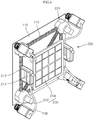
- FIG. 6 is a perspective view of a display module assembling apparatus according to one embodiment of the present disclosure
- FIG. 7 is a perspective view illustrating a state in which a display module is assembled using the display module assembling apparatus according to one embodiment of the present disclosure
- FIG. 8 is a cross-sectional view illustrating the state in which the display module is assembled using the display module assembling apparatus according to one embodiment of the present disclosure.
- a configuration of the display assembly apparatus 200 of the present embodiment is as follows.
- the display module assembly apparatus 200 of the present embodiment may include a frame 210 located on the front side of the display module 110.
- At least one rotation module 220 may be provided at one side of the frame 210 and be installed to correspond to the above-described mounting apparatus 150.
- the rotation module 220 may generate attractive force to the mounting apparatus 150, rotate the interlocked rotational engagement body 160 of the mounting apparatus 150 using the attractive force, and couple the display module 110 to the profile structure body 130.
- the mounting apparatus 150 may be fixed to a rear side of the display module 110 at a predetermined position away from a corner of the display module 110.
- the rotation module 220 of the display module assembly apparatus 200 may be provided at a position corresponding to the mounting apparatus 150 on the front side of the display module 110.
- the display module assembly apparatus 200 may accurately rotate the interlocked rotational engagement body 160.
- the rotation module 220 may include a housing 222 installed at one side of the frame 210.
- the housing 222 is installed at one side of the frame 210, and preferably, a position of the housing 222 may be adjusted and located at a predetermined position corresponding to the mounting apparatus 150 away from the corner of the display module 110.
- a motor 224 may be installed inside the housing 222 via a bracket or the like. Furthermore, a rotational interlocking portion 226 may be provided at a rotational shaft of the motor 224 to rotate the interlocked rotational engagement body 160 of the mounting apparatus 150.
- the rotational interlocking portion 226 may include a magnetic force generation portion 227 configured to generate a magnetic force to the magnetic member 166 of the interlocked rotational engagement body 160 and rotate the engagement member 164.
- the magnetic force generation portion 227 may be provided as a permanent magnet or an electromagnet module and have polarity apposite polarity of the magnetic member 166 of the interlocked rotational engagement body 160.
- the magnetic force generation portion 227 generates attractive force to the magnetic member 166 of the interlocked rotational engagement body 160, and thus the magnetic force generation portion 227 of the rotational interlocking portion 226 is rotated by the motor 224.
- the magnetic member 166 of the interlocked rotational engagement body 160 may be rotated by the attractive force in response to the rotation of the magnetic force generation portion 227, the engagement member 164 coupled to the magnetic member 166 may be rotated, and thus the mounting apparatus 150 may be attached to or detached from the engagement plate 132 of the structure 130.
- a switch 213 may be provided at one side of the frame 210 to control a supply of electricity to the electromagnet module.
- a handle 212 may be provided at one side of the frame 210 to facilitate an operator to grip the assembly apparatus 200, and the switch 213 may be provided at position of a thumb of the operator so as to allow the operator to control a supply of electricity to the magnetic force generation portion 227, i.e., the electromagnet module in a state in which the operator holds the handle 212.
- the magnetic force generation portion 227 has been described as having the polarity opposite the polarity of the magnetic member 166 of the interlocked rotational engagement body 160 in the present embodiment, but the magnetic force generation portion 227 may be disposed to have a polarity the same as the polarity of the magnetic member 166, and at this point, a repulsive force may be generated against a magnetic force generated in the force generation portion 227 such that magnetic member 166 may be rotated.
- the rotational interlocking portion 226 may further include an auxiliary bearing unit 228 configured to rotatably support the magnetic force generation portion 227 so as to prevent the magnetic force generation portion 227 from being in contact with the display module 110 while the magnetic force generation portion 227 is rotated.
- an auxiliary bearing unit 228 configured to rotatably support the magnetic force generation portion 227 so as to prevent the magnetic force generation portion 227 from being in contact with the display module 110 while the magnetic force generation portion 227 is rotated.
- the auxiliary bearing unit 228 may rotatably support the magnetic force generation portion 227.
- the auxiliary bearing unit 228 may be provided at various positions for guiding the rotation of the magnetic force generation portion 227.
- the auxiliary bearing unit 228 may be provided to be in close contact with a front surface portion of the display module 110.
- a contact pad may be provided at the auxiliary bearing unit 228 to be in soft contact with the front surface portion of the display module 110. Accordingly, the contact pad may minimize damage of the display module 110 due to lessen a frictional force between the auxiliary bearing unit 228 and the display module 110.
- the auxiliary bearing unit 228 may rotatably support a rear side of the magnetic force generation portion 227 without being in close contact with the front side of the display module 110.
- the assembly apparatus 200 of the present embodiment may further include an alignment unit 230 configured to align the rotation module 220 to a position corresponding to the mounting apparatus 150 by sensing corners of the display module 110.
- the alignment unit 230 may include at least one image capturing unit 232 installed at one side of the rotation module 220 and an image display unit 234 configured to display an image captured by the image capturing unit 232.
- the image capturing unit 232 and the image display unit 234 may be connected through an electric wire 236, and be connected using wireless communication.
- the operator may recognize a position of corners of the display module 110 by checking the image displayed on the image display unit 234, and, if the image displayed on the image display unit 234 shows if the display module 110 lies at an expected position around the corners, the operator may check an interval between corners of adjacent display modules 110.
- the operator may determine pitches between outermost pixels of the display module 110 and the adjacent display module 110, which are displayed on the image display unit 234, and the operator may align the position of the display module 110 to make the same interval, i.e., the same pitch between the adjacent display modules 110 using the display module assembly apparatus 200.
- the rotation module 220 may be automatically coupled to a position which is accurately aligned with the mounting apparatus 150 installed at the rear side of the display module 110.
- the multi-display device 1 is provided in a form of a narrow bezel type or a zero bezel type in which there is almost no interval between the display modules 10 connected to each other.
- the alignment unit 230 may also automatically control the position of the display module 110.
- the alignment unit 230 may further include a position correction unit (not shown) configured to move the rotation module 220 to a position corresponding to the mounting apparatus 150 on the basis of the corner captured by the image capturing unit 232.
- a position correction unit (not shown) configured to move the rotation module 220 to a position corresponding to the mounting apparatus 150 on the basis of the corner captured by the image capturing unit 232.
- the position correction unit may include a plurality of variable length members provided between the frame 210 and the rotation module 220, and a position of the rotation module 220 may be moved according to a varied length of the plurality of variable length members such that the display module 110 may be automatically aligned with the position corresponding to the mounting apparatus 150.
- variable length member may be a member of which length is adjusted by the motor 224, or is adjusted by a cylinder.
- a coupling structure and an engagement structure of the mounting apparatus 150 are not limited to the described above and these may be modified in various forms.
- the nut member 134 provided on a rear side of an engagement plate 132 may be movably provided to have a predetermined clearance while the engagement member 164 of the mounting apparatus 150 is coupled to the nut member 134, and to this end, a nut coupling portion including the nut member 134 may be provided.
- the nut coupling portion may include the nut member 134 coupled to the engagement member 164 at the rear side of the engagement plate 132 and to which the mounting apparatus 150 is fixed.
- the nut member 134 may be configured to be freely movable in a state of being coupled or attached to the engagement plate 132.
- the nut coupling portion may include a nut housing 135 configured to position the movably provided nut member 134 on the rear side of the engagement plate 132.
- the nut housing 135 may be provided to block surroundings of the through-hole 163 at the rear side of the engagement plate 132. Further, the nut member 134 may be accommodated inside the nut housing 135.
- an inner diameter of the nut housing 135 may be formed to be larger than an outer diameter of the nut member 134, and thus the nut member 134 may be accommodated to move in an inner space of the nut housing 135.
- the inner diameter of the nut housing 135 may be formed to be smaller than a maximum thickness of the nut member 134, and thus the nut member 134 may move freely in a gap between the nut housing 135 and the engagement plate 132 but may not be laid down in a straight upright state.
- the inner diameter of the nut housing 135 may be made to be larger, and thus the nut member 134 may be prevented from being laid down and as well, a gap between the nut member 134 and the nut housing 135 may be formed to be larger.
- the display module assembly method may include attaching step, moving step, and coupling step.
- the mounting apparatus 150 is installed on the rear side of the display module 110.
- the second wheel 174 of the bearing unit 170 of the mounting apparatus 150 may be attached to the rear side of the display module 110 via a member such as an adhesive or the like.
- the display module 110 coupled to the mounting apparatus 150 is disposed close to the profile structure body 130 located behind the display module 110.
- the operator moves the display module 110 using the display module assembly apparatus 200, and places the display module 110 ahead of the profile structure body 130 to assemble the display module 110.
- attraction may be generated at the magnetic member 166 of the mounting apparatus 150 by a magnetic force generated at the magnetic force generation portion 227 of the rotation module 220, and thus the display module 110 may be attached to the rotation module 220 of the display assembly apparatus 200.
- the magnetic force generation portion 227 of the rotation module 220 may be magnetized to generate the magnetic force by power which is provided when the operator presses the switch 213 attached to the grip 212.
- the moving step may be performed.
- the display module 110 is moved in a state of being attached to the display module assembly apparatus 200 provided ahead of the display module 110.
- the operator may grip the handle 212 of the display module assembly apparatus 200 and easily move the display module 110 to an attachment position of the profile structure body 130.
- the display module assembly apparatus 200 may locate the display module 110 ahead of the profile structure body 130 and couple the display module 110 to the profile structure body 130.
- the coupling step may further include aligning step of an attachment position of the display module 110 in a state in which the display module 110 is located ahead of the attachment position of the profile structure body 130.
- the aligning step aligns the mounting apparatus 150 with the accommodation recess 133 of the engagement plate 132.
- the operator moves the display module 110 to the attachment position of the profile structure body 130 while checking the corner of the display module 110 using the display module assembly apparatus 200.
- the mounting apparatus 150 may be installed at a predetermined position the rear side of the display module 110 around the corner, and the mounting apparatus 150 may be aligned with an engagement position of the profile structure body 130, wherein the mounting apparatus 150 will be mounted at the engagement position, while the operator monitors corners of the display module 110.
- the operator may align the display module 110 through the alignment unit 230 of the display module assembly apparatus 200.
- the alignment unit 230 captures the corner of the display module 110 and displays the captured corner on the image display unit 234.
- the operator may determine the corner of the display module 110 displayed on the image display unit 234, align the corner of the display module 110 with corners of adjacent display modules 110 so as to allow the corner of the display module 110 to be kept constant with the corners of the adjacent display modules 110, and determine a position at which the display module 110 will be mounted on the profile structure body 130.
- the operator may align the position of the display module 110 by recognizing an interval between the adjacent display modules 110 at the corner of the display module 110 using the alignment unit 230.
- the operator may determine the corner of the display module 110 displayed on the image display unit 234, check and adjust the mounting position of the display module 110, rotate the mounting apparatus 150 using the rotation module 220 of the assembly apparatus 200, and assemble the display module 110 to the profile structure body 130, thereby completing the assembly.
- the display module assembly apparatus 200 may rotate the rotation module 220.
- the rotation member 220 is rotated as the magnetic member 166 is rotated, and thus the mounting apparatus 150 attached to the rear side of the display module 110 is rotated.
- the second wheel 174 of the bearing unit 170 is in a state of being fixed to the rear side of the display module 110, and the first wheel 172 connected via the rolling member 176 is attached to the disc 162 of the interlocked rotational engagement body 160.
- the disc 162 is rotated with the magnetic member 166 while being supported on the first wheel 172.
- the bearing unit 170 may support a rotation of the interlocked rotational engagement body 160 which is rotated by interlocking with the rotation module 220.
- the rotation of the interlocked rotational engagement body 160 is interlocked such that the magnetic member 166 senses attractive force generated in the magnetic force generation portion 227 of the rotation module 220.
- a rotational force interlocked with the magnetic member 166 is transmitted to the engagement member 164 and the disc 162 of the interlocked rotational engagement body 160 such that the engagement member 164 is coupled to the engagement plate 132 provided at the profile structure body 130 in a state of being rotatably supported on the first wheel 172.
- the display module 110 may be assembled to the profile structure body 130 on the front side of a multi-display device 100 using the display module assembly apparatus 200, and the assembly is performed while an assembled position, a stepped level, and the like are checked with the naked eye.
- a plurality of display modules can be easily attached or detached in a multi-display device at a front surface of the multi-display device.
- a corresponding display module can be selected and removed without an overall disassembly.
- a work can be performed while a stepped level of the display module is determined at the front side of the display module when the display module is installed, the work can be easily performed and as well, an arrangement state can be adjusted more accurately such that an alignment work can be more accurately easily performed.
- any engagement means or space is not required at the front side of the display module, an interval between the display modules can be further reduced. Accordingly a display quality can be improved because distortion of display at a border area can be reduced, where the adjacent display modules meet.
- the display module can be removed from a multi-display device at the front side of the display module, any additional work at the rear side of the display module is unnecessary. Accordingly any additional configuration for separating or rotating a profile structure body for a work at the rear side of the display module is not required, and thus an entire volume of the display module can be further reduced such that there is advantageous for space utilization, various arrangement is possible according to an installation space, and infinite expansion is possible.
Landscapes
- Engineering & Computer Science (AREA)
- General Engineering & Computer Science (AREA)
- Physics & Mathematics (AREA)
- Mechanical Engineering (AREA)
- Theoretical Computer Science (AREA)
- Electromagnetism (AREA)
- General Physics & Mathematics (AREA)
- Multimedia (AREA)
- Power Engineering (AREA)
- Microelectronics & Electronic Packaging (AREA)
- Human Computer Interaction (AREA)
- Computer Security & Cryptography (AREA)
- Devices For Indicating Variable Information By Combining Individual Elements (AREA)
Abstract
Description
- The present disclosure relates to a mounting apparatus and an apparatus and a method for assembling a display module using the same, and more particularly, to a mounting apparatus in which an engagement portion is not exposed to the outside when a panel is connected, and an apparatus and method for assembling a display module using the same.
- Generally, a display module is a device for displaying visual information and is used in various fields such as mobile phones, television, personal digital assistants (PDAs), digital cameras, and computer monitors.
- The display module is manufactured in a large scale according to the development of information technology, and a curved surface display module in which a curvature is formed on a surface of the display module is developed and used.
- Recently, as shown in
FIG. 1 , amulti-display device 1 in which a plurality ofdisplay modules 10 are connected to extend a display area and a limit of visual information has been used. - The
multi-display device 1 is provided in a form of a narrow bezel type or a zero bezel type in which there is almost no interval between the plurality ofdisplay modules 10 connected to each other. - Further, the
multi-display device 1 may include aprofile structure body 30 configured to mount the plurality ofdisplay modules 10 thereon. Theprofile structure body 30 may be provided in a grid shaped frame structure to support the plurality ofdisplay modules 10. - Meanwhile, since there is almost no interval between the plurality of
display modules 10 in themulti-display device 1, there is a structural limitation in that the plurality ofdisplay modules 10 cannot be coupled to theprofile structure body 30 in front of each of the plurality ofdisplay modules 10. - Accordingly, in case of the conventional
multi-display device 1, the plurality ofdisplay modules 10 are installed to theprofile structure body 30 in the rear of the plurality ofdisplay modules 10 using engagement members such as bolts, clamps, and the like. - In a state in which the plurality of
display modules 10 are installed at theprofile structure body 30, themulti-display device 1 may be installed on one's feet by embedding theprofile structure body 30 in a wall surface or the like, or coupling a separate support member and a housing to theprofile structure body 30. - Further, if one of the plurality of
display modules 10 is needed to be repaired or replaced, it is difficult to separate the one of the plurality ofdisplay modules 10 from the conventionalmulti-display device 1 because an engagement portion is not exposed on a front side of the conventionalmulti-display device 1. - Further, there may conventionally be a mechanism tolerance of the
profile structure body 30 at which the plurality ofdisplay modules 10 are installed, and accordingly, it is difficult to perform an alignment operation for accurately arranging the plurality ofdisplay modules 10 at theprofile structure body 30. Furthermore, since a coupling operation for the plurality ofdisplay modules 10 is performed in the rear of the conventionalmulti-display device 1, a coupled state of a front surface of each of the plurality ofdisplay modules 10 cannot be determined and thus conditions of the plurality ofdisplay modules 10 such as the coupled state or a stepped level cannot be recognized. Accordingly, it results inconvenience because the conditions of the front side of each of the plurality ofdisplay modules 10 should frequently be checked during assembly. - Furthermore, owing to a conventional installation structure of each of the plurality of
display modules 10, detaching or attaching of each of the plurality ofdisplay modules 10 is not easy, a large amount of work time is required, work difficulty is very high, and thus overall productivity is deteriorated such that there is an increasing need to improve an installation structure of the plurality ofdisplay modules 10. - Therefore, it is an objective of the present disclosure to provide an improved mounting apparatus for improving an installation structure of a display module and selectively detaching or attaching singular display module required for replacement or repair, and an apparatus and method for assembling a display module using the same.
- Objects of the present disclosure are not limited to the above-described objects and other objects and advantages can be appreciated by those skilled in the art from the following descriptions. Further, it will be easily appreciated that the objects and advantages of the present disclosure can be practiced by means recited in the appended claims and a combination thereof.
- There is provided a mounting apparatus comprising an interlocked rotational engagement body including an engagement member, and a magnetic member fixed to the engagement member.
- The mounting apparatus may be adapted to be fixed to an engagement plate by a rotational movement of the engagement member induced by a magnetic force acting on the magnetic member.
- The interlocked rotational engagement body may further comprise a disc including a through-hole and a stepped seating recess and the engagement member may comprise a body passing through the through-hole and a head portion, wherein the head portion and the magnetic member are seated, in particular hooked, in the stepped seating recess.
- The mounting apparatus may further comprise a bearing unit, wherein the bearing unit includes a first wheel, and a second wheel; wherein the first wheel is attached to the interlocked rotational engagement body. In particular, the first wheel may be attached to the disc.
- The bearing unit may further comprise a rolling member.
- The bearing unit may further comprise a retainer, wherein the rolling member is rotatably coupled by the retainer between the first wheel and the second wheel.
- It is further provided a display module comprising a display panel, and at least one aforementioned mounting apparatus, wherein the mounting apparatus is fixed to a backside of the display panel. In particular, the second wheel of the mounting apparatus may be fixed to the backside of the display panel.
- It is provided a profile structure body comprising at least one engagement plate adapted to receive an aforementioned display module.
- The engagement plate may comprise an accommodation recess for accommodating the mounting apparatus.
- The profile structure body may further comprise a nut member, wherein the nut member is adapted to receive the body of the engagement member, and a nut housing, wherein the nut member is accommodated in the nut housing.
- It is further provided a rotation module comprising a rotatable magnetic force generation portion adapted for rotating the interlocked rotational engagement body of an aforementioned mounting apparatus by magnetic forces acting on the magnetic member of mounting apparatus.
- The magnetic force generation portion may comprise an electromagnet module.
- The rotation module may comprise a motor.
- The rotation module may comprise an auxiliary bearing unit.
- It is further proposed a display module assembly apparatus comprising at least one aforementioned rotation module, wherein the display module assembly apparatus is adapted for fastening an aforementioned display module to an aforementioned profile structure body according to any one of claims.
- The display module assembly apparatus may further comprise an alignment unit including an image capturing unit for capturing an image of a corner of the display module.
- The alignment unit may further comprise an image display unit.
- The alignment unit may further comprises a position correction unit.
- It is further proposed a multi-display device comprising at least one aforementioned display module and an aforementioned profile structure.
- There is provided a mounting apparatus including at least one interlocked rotational engagement body interlocked and rotated with an assembling apparatus located on a front surface of a display module, and coupled to a profile structure body provided on a rear surface of the display module; and a bearing unit having a first wheel attached to the at least one interlocked rotational engagement body, and a second wheel attached to one side of the rear surface of the display module, and to which the at least one interlocked rotational engagement body is rotatably coupled.
- The interlocked rotational engagement body may include a disc having an outer circumferential portion attached to the first wheel of the bearing unit; an engagement member having a body coupled to pass through a central portion of the disk and coupled to the profile structure body, and a head portion formed at a rear end portion of the body and hooked to the disk; and a magnetic member provided on at least one side of the head portion and configured to rotate the engagement member by a magnetic force.
- A seating groove may be formed at the disc to allow the head portion and the magnetic member to be seated on the seating recess.
- The profile structure body may include a plurality of profiles connected to each other; an engagement plate coupled to the plurality of profiles and having a through-hole corresponding to the engagement member at one side of the engagement plate; and a nut coupling portion provided behind the through-hole of the engagement plate, and to which the engagement member is coupled.
- The nut coupling portion may include a nut member coupled to the engagement member; a nut housing provided to block surroundings of the through-hole on a rear surface of the engagement plate, and configured to accommodate the nut member in a state in which the nut member is straight upright.
- The bearing unit may include a thrust ball bearing having a plurality balls between the first wheel and the second wheel.
- The bearing unit may include a thrust needle roller bearing having a plurality of truncated conical rollers between the first wheel and the second wheel.
- There is provided an apparatus for assembling a display module, which includes a frame located on a front surface of a display module; and at least one rotation module installed at one side of the frame by corresponding to the above-described mounting apparatus, configured to generate attraction to the mounting apparatus, and being in close contact with the display module.
- The at least one rotation module may include a housing installed at the frame; and a motor installed inside the housing; and a rotational interlocking portion rotated by being connected to a rotational shaft of the motor and configured to rotate an interlocked rotational engagement body of the mounting apparatus.
- The rotational interlocking portion may include a magnetic force generation portion configured to generate a magnetic force to the magnetic member to rotate an engagement member.
- The magnetic force generation portion may include an electromagnet module, and a switch is provided at one side of the frame to control a supply of electricity to the electromagnet module.
- The mounting apparatus may be installed at a predetermined position on the basis of a corner of the display module, and the apparatus for assembling a display module may further include an alignment unit configured to sense a corner of adjacent display module and align the at least one rotation module to a position corresponding to the mounting apparatus.
- The alignment unit may recognize an interval between adjacent display modules at the corner of the display module and aligns a position of the display module.
- The alignment unit may include at least one image capturing unit installed at one side of the rotation module and configured to capture an image of the corner of the display module; and an image display unit installed at one side of the frame and configured to display an image captured by the at least one image capturing unit.
- There is provided a method for assembling a display module, which includes attaching the above-described apparatus for assembling a display module to a front surface portion of the display module to which a mounting apparatus is attached; moving the display module to an attachment position of a front surface portion of a profile structure body using the apparatus for assembling a display module; and coupling the display module to the attachment position.
- The attaching may include aligning an attachment position of the display module using an alignment unit of the display module.
- The aligning may include aligning a position of the display module while maintaining a constant interval between the display module and adjacent display modules at a corner of the display module through an image display unit of the aligning unit.
- The coupling may include rotating an interlocked rotational engagement body of the mounting apparatus provided at the display module in responding to a rotation of a rotation module; and coupling the display module to a profile structure body.
-
-
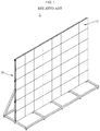
FIG. 1 is a perspective view of a multi-display device. -
FIG. 2 is a perspective view illustrating a state in which the multi-display device is assembled using an assembling apparatus according to one embodiment of the present disclosure. -
FIG. 3 is a side view illustrating the state in which the multi-display device is assembled using the assembling apparatus according to one embodiment of the present disclosure. -
FIG. 4 is a perspective view illustrating a part of a mounting apparatus according to one embodiment of the present disclosure. -
FIG. 5 is an exploded perspective view of the mounting apparatus according to one embodiment of the present disclosure. -
FIG. 6 is a perspective view of a display module assembling apparatus according to one embodiment of the present disclosure. -
FIG. 7 is a perspective view illustrating a state in which a display module is assembled using the display module assembling apparatus according to one embodiment of the present disclosure. -
FIG. 8 is a cross-sectional view illustrating the state in which the display module is assembled using the display module assembling apparatus according to one embodiment of the present disclosure. - Certain terms are defined herein for easy understanding. Unless specifically defined herein, scientific and technical terms used herein shall have the meanings commonly understood by those skilled in the art. As used herein, the singular forms are intended to include plural forms and vice versa, unless the context clearly indicates otherwise.
-
FIG. 2 is a perspective view illustrating a state in which the multi-display device is assembled using an assembling apparatus according to one embodiment of the present disclosure, andFIG. 3 is a side view illustrating the state in which the multi-display device is assembled using the assembling apparatus according to one embodiment of the present disclosure. Further,FIG. 4 is a perspective view illustrating a part of a mounting apparatus according to one embodiment of the present disclosure, andFIG. 5 is an exploded perspective view of the mounting apparatus according to one embodiment of the present disclosure. - Hereinafter, a mounting
apparatus 150 and a displaymodule assembly apparatus 200 including the mountingapparatus 150 according to one embodiment of the present disclosure will be described with reference toFIGS. 2 to 5 . - The mounting
apparatus 150 according to one embodiment of the present disclosure is an apparatus configured to couple adisplay module 110 to aprofile structure body 130. Theprofile structure body 130 may be installed at a wall surface, a place at which themulti-display device 1 is installed, a separate support member, or the like. - Further, the
display module 110 may directly be coupled to theprofile structure body 130 via the mountingapparatus 150, and also anengagement plate 132 to which a coupling member such as a bracket or a nut, which is coupled to the mountingapparatus 150, is coupled may be provided at theprofile structure body 130. - An
accommodation recess 133 may be formed at theengagement plate 132 to accommodate the mountingapparatus 150, and anut member 134 for a coupling may be provided at a rear side of theaccommodation recess 133. - The mounting
apparatus 150 may include at least one interlockedrotational engagement body 160. The interlockedrotational engagement body 160 may be coupled to theprofile structure body 130 provided at a rear side of thedisplay module 110. - The interlocked
rotational engagement body 160 may be rotated by being interlocked with the displaymodule assembly apparatus 200 located at a front side of thedisplay module 110. At this point, the interlockedrotational engagement body 160 may be provided to be rotated without a physical contact with the displaymodule assembly apparatus 200. - Further, the mounting
apparatus 150 may rotatably be coupled to the rear side of thedisplay module 110, and, to this end, abearing unit 170 to which the mountingapparatus 150 is rotatably coupled may be provided between the mountingapparatus 150 and the rear surface of thedisplay module 110. - The
bearing unit 170 may include afirst wheel 172 having one side attached to the interlockedrotational engagement body 160 and asecond wheel 174 having one side attached to one side of the rear side of thedisplay module 110, and rollingmember 176 may rotatably be coupled by aretainer 178 between thefirst wheel 172 and thesecond wheel 174. - Specifically, the interlocked
rotational engagement body 160 may include adisc 162 having an outer circumferential portion attached to thefirst wheel 172 of thebearing unit 170, and anengagement member 164 may be provided at thedisc 162 to be coupled to theprofile structure body 130. - To this end, a through-
hole 163 may be formed at a central portion of thedisc 162. - A plurality of
protrusion parts 169 can be formed on an outer circumferential portion of thedisc 162 and they are isolated from each other along the outer circumferential portion of thedisc 162. - When the
disc 162 is coupled to its counterpart by means of a screw, theprotrusion parts 169 function to reduce a gap between the components but to increase friction force between them, thereby preventing the coupling between them from being decoupled. - The
protrusion parts 169 can be formed by use of a press processing. - According to an exemplary embodiment of the present invention, the
protrusion parts 169 are formed in the trapezoid shape, but they are not limited to this shape. - Further, the
engagement member 164 may include abody 164a coupled to pass through the through-hole 163 of thedisc 162, and ahead portion 164b formed at a rear end portion of thebody 164a and hooked to thedisc 162. - A spiral portion may be formed on an outer circumferential surface of the
body 164a and be screw-engaged with theprofile structure body 130 by passing through thedisc 162. Theengagement member 164 may be kept in a state of being coupled to theprofile structure body 130 as thehead portion 164b is hooked to and is in close contact with thedisc 162 while thebody 164a is coupled to theprofile structure body 130. - Further, a
magnetic member 166 may be installed on at least one side of thehead portion 164b to rotate theengagement member 164 by a magnetic force. - Preferably, the
head portion 164b of theengagement member 164 may be attached to thedisc 162 via an adhesive or the like, and thus thedisc 162 and theengagement member 164 may be integrally rotated. - Further, a stepped
seating recess 163a may be formed at thedisc 162 to allow thehead portion 164b and themagnetic member 166 to be seated on and fixed to the steppedseating recess 163a, and thus thedisc 162 and theengagement member 164 may be more firmly coupled and integrally rotated. - In the present embodiment, a neodymium magnet may be used as the
magnetic member 166, and an electromagnet magnetized by a supply of an induced current may be used in addition to the neodymium magnet. - In the present embodiment, the
magnetic member 166 may be symmetrically provided at both sides of thehead portion 164b on the basis of the center thereof. - Further, in the present embodiment, a plurality of balls may be used as the rolling
member 176 between thefirst wheel 172 and thesecond wheel 174 of thebearing unit 170, and thebearing unit 170 may include a plurality of thrust balls bearing configured to support a load generated in an axial direction. - Furthermore, in the present embodiment, the
bearing unit 170 has been described as the thrust ball bearing, but in consideration of a working load and the like, a thrust needle roller bearing having a truncated conical roller may be included in thebearing unit 170 as the rollingmember 176 between thefirst wheel 172 and thesecond wheel 174. - In addition, the
bearing unit 170 may employ commercially available various types and kinds of bearings, and thebearing unit 170 may include various types of bearings, such as an angular bearing and the like, having a self-aligning function while supporting an axial load in addition to the thrust ball bearing and the thrust needle roller bearing. - Additionally, in the present embodiment, the interlocked
rotational engagement body 160 and thefirst wheel 172, and thesecond wheel 174 and the rear surface of thedisplay module 110 may be attached via an adhesive, be physically engaged by theengagement member 164 such as a bolt and the like, be coupled by installing an engaging member such as a hook and the like or a bracket, or be coupled by welding or the like. Coupling structures for the interlockedrotational engagement body 160 and thefirst wheel 172, and thesecond wheel 174 and the rear surface of thedisplay module 110 are not limited to the described above, and the coupling structures may be modified in various forms. - As shown in
FIG. 7 , the mountingapparatus 150 configured as described above may couple thedisplay module 110 to theprofile structure body 130 as the interlockedrotational engagement body 160 is rotated by the displaymodule assembly apparatus 200 disposed on the front side of thedisplay module 110. -
FIG. 6 is a perspective view of a display module assembling apparatus according to one embodiment of the present disclosure, andFIG. 7 is a perspective view illustrating a state in which a display module is assembled using the display module assembling apparatus according to one embodiment of the present disclosure. Further,FIG. 8 is a cross-sectional view illustrating the state in which the display module is assembled using the display module assembling apparatus according to one embodiment of the present disclosure. - Referring to
FIGS. 6 to 8 , a configuration of thedisplay assembly apparatus 200 of the present embodiment is as follows. - The display
module assembly apparatus 200 of the present embodiment may include aframe 210 located on the front side of thedisplay module 110. - Further, at least one
rotation module 220 may be provided at one side of theframe 210 and be installed to correspond to the above-describedmounting apparatus 150. - The
rotation module 220 may generate attractive force to the mountingapparatus 150, rotate the interlockedrotational engagement body 160 of the mountingapparatus 150 using the attractive force, and couple thedisplay module 110 to theprofile structure body 130. - For example, in the present embodiment, the mounting
apparatus 150 may be fixed to a rear side of thedisplay module 110 at a predetermined position away from a corner of thedisplay module 110. - Further, the
rotation module 220 of the displaymodule assembly apparatus 200 may be provided at a position corresponding to the mountingapparatus 150 on the front side of thedisplay module 110. - Since the
rotation module 220 is disposed to correspond to the mountingapparatus 150, the displaymodule assembly apparatus 200 may accurately rotate the interlockedrotational engagement body 160. - To this end, the
rotation module 220 may include ahousing 222 installed at one side of theframe 210. Thehousing 222 is installed at one side of theframe 210, and preferably, a position of thehousing 222 may be adjusted and located at a predetermined position corresponding to the mountingapparatus 150 away from the corner of thedisplay module 110. - Further, a
motor 224 may be installed inside thehousing 222 via a bracket or the like. Furthermore, arotational interlocking portion 226 may be provided at a rotational shaft of themotor 224 to rotate the interlockedrotational engagement body 160 of the mountingapparatus 150. - Moreover, the
rotational interlocking portion 226 may include a magneticforce generation portion 227 configured to generate a magnetic force to themagnetic member 166 of the interlockedrotational engagement body 160 and rotate theengagement member 164. - The magnetic
force generation portion 227 may be provided as a permanent magnet or an electromagnet module and have polarity apposite polarity of themagnetic member 166 of the interlockedrotational engagement body 160. The magneticforce generation portion 227 generates attractive force to themagnetic member 166 of the interlockedrotational engagement body 160, and thus the magneticforce generation portion 227 of therotational interlocking portion 226 is rotated by themotor 224. Further, as the magneticforce generation portion 227 of therotational interlocking portion 226 is rotated, themagnetic member 166 of the interlockedrotational engagement body 160 may be rotated by the attractive force in response to the rotation of the magneticforce generation portion 227, theengagement member 164 coupled to themagnetic member 166 may be rotated, and thus the mountingapparatus 150 may be attached to or detached from theengagement plate 132 of thestructure 130. - Furthermore, if the magnetic
force generation portion 227 is configured as an electromagnet module, aswitch 213 may be provided at one side of theframe 210 to control a supply of electricity to the electromagnet module. Preferably, ahandle 212 may be provided at one side of theframe 210 to facilitate an operator to grip theassembly apparatus 200, and theswitch 213 may be provided at position of a thumb of the operator so as to allow the operator to control a supply of electricity to the magneticforce generation portion 227, i.e., the electromagnet module in a state in which the operator holds thehandle 212. - While the magnetic
force generation portion 227 has been described as having the polarity opposite the polarity of themagnetic member 166 of the interlockedrotational engagement body 160 in the present embodiment, but the magneticforce generation portion 227 may be disposed to have a polarity the same as the polarity of themagnetic member 166, and at this point, a repulsive force may be generated against a magnetic force generated in theforce generation portion 227 such thatmagnetic member 166 may be rotated. - Further, the
rotational interlocking portion 226 may further include anauxiliary bearing unit 228 configured to rotatably support the magneticforce generation portion 227 so as to prevent the magneticforce generation portion 227 from being in contact with thedisplay module 110 while the magneticforce generation portion 227 is rotated. - The
auxiliary bearing unit 228 may rotatably support the magneticforce generation portion 227. - Although the
auxiliary bearing unit 228 has been described as being installed between the magneticforce generation portion 227 and thehousing 222 in the present embodiment, theauxiliary bearing unit 228 may be provided at various positions for guiding the rotation of the magneticforce generation portion 227. For example, theauxiliary bearing unit 228 may be provided to be in close contact with a front surface portion of thedisplay module 110. Here, a contact pad may be provided at theauxiliary bearing unit 228 to be in soft contact with the front surface portion of thedisplay module 110. Accordingly, the contact pad may minimize damage of thedisplay module 110 due to lessen a frictional force between theauxiliary bearing unit 228 and thedisplay module 110. - Alternatively, in the present embodiment, the
auxiliary bearing unit 228 may rotatably support a rear side of the magneticforce generation portion 227 without being in close contact with the front side of thedisplay module 110. - The
assembly apparatus 200 of the present embodiment may further include analignment unit 230 configured to align therotation module 220 to a position corresponding to the mountingapparatus 150 by sensing corners of thedisplay module 110. - For example, the
alignment unit 230 may include at least oneimage capturing unit 232 installed at one side of therotation module 220 and animage display unit 234 configured to display an image captured by theimage capturing unit 232. - The
image capturing unit 232 and theimage display unit 234 may be connected through anelectric wire 236, and be connected using wireless communication. - The operator may recognize a position of corners of the
display module 110 by checking the image displayed on theimage display unit 234, and, if the image displayed on theimage display unit 234 shows if thedisplay module 110 lies at an expected position around the corners, the operator may check an interval between corners ofadjacent display modules 110. - When the position of the corner is determined while a position of the
display module 110 is aligned, the operator may determine pitches between outermost pixels of thedisplay module 110 and theadjacent display module 110, which are displayed on theimage display unit 234, and the operator may align the position of thedisplay module 110 to make the same interval, i.e., the same pitch between theadjacent display modules 110 using the displaymodule assembly apparatus 200. - As described above, when the operator disposes the
display module 110 to have a predetermined interval between theadjacent display modules 110 using theimage display unit 234, therotation module 220 may be automatically coupled to a position which is accurately aligned with the mountingapparatus 150 installed at the rear side of thedisplay module 110. - The
multi-display device 1 is provided in a form of a narrow bezel type or a zero bezel type in which there is almost no interval between thedisplay modules 10 connected to each other. - Although the
alignment unit 230 has been described as being aligned by the operator who checks the image captured in theimage capturing unit 232 in the present embodiment, thealignment unit 230 may also automatically control the position of thedisplay module 110. - To this end, the
alignment unit 230 may further include a position correction unit (not shown) configured to move therotation module 220 to a position corresponding to the mountingapparatus 150 on the basis of the corner captured by theimage capturing unit 232. - The position correction unit may include a plurality of variable length members provided between the
frame 210 and therotation module 220, and a position of therotation module 220 may be moved according to a varied length of the plurality of variable length members such that thedisplay module 110 may be automatically aligned with the position corresponding to the mountingapparatus 150. - For example, the variable length member may be a member of which length is adjusted by the
motor 224, or is adjusted by a cylinder. - Although the mounting
apparatus 150 is described as being coupled to the rear side of theprofile structure body 130 via anut member 134 in the present embodiment, a coupling structure and an engagement structure of the mountingapparatus 150 are not limited to the described above and these may be modified in various forms. - For example, referring to
FIG. 8 , thenut member 134 provided on a rear side of anengagement plate 132 may be movably provided to have a predetermined clearance while theengagement member 164 of the mountingapparatus 150 is coupled to thenut member 134, and to this end, a nut coupling portion including thenut member 134 may be provided. - The nut coupling portion may include the
nut member 134 coupled to theengagement member 164 at the rear side of theengagement plate 132 and to which the mountingapparatus 150 is fixed. Here, thenut member 134 may be configured to be freely movable in a state of being coupled or attached to theengagement plate 132. - Further, the nut coupling portion may include a nut housing 135 configured to position the movably provided
nut member 134 on the rear side of theengagement plate 132. - The nut housing 135 may be provided to block surroundings of the through-
hole 163 at the rear side of theengagement plate 132. Further, thenut member 134 may be accommodated inside the nut housing 135. - Here, an inner diameter of the nut housing 135 may be formed to be larger than an outer diameter of the
nut member 134, and thus thenut member 134 may be accommodated to move in an inner space of the nut housing 135. - Preferably, the inner diameter of the nut housing 135 may be formed to be smaller than a maximum thickness of the
nut member 134, and thus thenut member 134 may move freely in a gap between the nut housing 135 and theengagement plate 132 but may not be laid down in a straight upright state. - Further, in the present embodiment, when a thickness of the
nut member 134 is increased, the inner diameter of the nut housing 135 may be made to be larger, and thus thenut member 134 may be prevented from being laid down and as well, a gap between thenut member 134 and the nut housing 135 may be formed to be larger. - A method for assembling a display module using the above-described mounting apparatus and the above-described display module assembling apparatus using the same will now be described below.
- The display module assembly method may include attaching step, moving step, and coupling step.
- First, in the attaching step, the mounting
apparatus 150 is installed on the rear side of thedisplay module 110. At this point, thesecond wheel 174 of thebearing unit 170 of the mountingapparatus 150 may be attached to the rear side of thedisplay module 110 via a member such as an adhesive or the like. - Next, the
display module 110 coupled to the mountingapparatus 150 is disposed close to theprofile structure body 130 located behind thedisplay module 110. - That is, the operator moves the
display module 110 using the displaymodule assembly apparatus 200, and places thedisplay module 110 ahead of theprofile structure body 130 to assemble thedisplay module 110. - When the display
module assembly apparatus 200 is located on the front side of thedisplay module 110 coupled to the mountingapparatus 150, attraction may be generated at themagnetic member 166 of the mountingapparatus 150 by a magnetic force generated at the magneticforce generation portion 227 of therotation module 220, and thus thedisplay module 110 may be attached to therotation module 220 of thedisplay assembly apparatus 200. The magneticforce generation portion 227 of therotation module 220 may be magnetized to generate the magnetic force by power which is provided when the operator presses theswitch 213 attached to thegrip 212. - As described above, after the
display module 110 is coupled to the displaymodule assembly apparatus 200, the the moving step may be performed. - The
display module 110 is moved in a state of being attached to the displaymodule assembly apparatus 200 provided ahead of thedisplay module 110. - When the
display module 110 is attached to the displaymodule assembly apparatus 200, the operator may grip thehandle 212 of the displaymodule assembly apparatus 200 and easily move thedisplay module 110 to an attachment position of theprofile structure body 130. - Next, in the coupling step, the display
module assembly apparatus 200 may locate thedisplay module 110 ahead of theprofile structure body 130 and couple thedisplay module 110 to theprofile structure body 130. - Preferably, the coupling step may further include aligning step of an attachment position of the
display module 110 in a state in which thedisplay module 110 is located ahead of the attachment position of theprofile structure body 130. - The aligning step aligns the mounting
apparatus 150 with theaccommodation recess 133 of theengagement plate 132. - At this point, the operator moves the
display module 110 to the attachment position of theprofile structure body 130 while checking the corner of thedisplay module 110 using the displaymodule assembly apparatus 200. - The mounting
apparatus 150 may be installed at a predetermined position the rear side of thedisplay module 110 around the corner, and the mountingapparatus 150 may be aligned with an engagement position of theprofile structure body 130, wherein the mountingapparatus 150 will be mounted at the engagement position, while the operator monitors corners of thedisplay module 110. - The operator may align the
display module 110 through thealignment unit 230 of the displaymodule assembly apparatus 200. Thealignment unit 230 captures the corner of thedisplay module 110 and displays the captured corner on theimage display unit 234. - The operator may determine the corner of the
display module 110 displayed on theimage display unit 234, align the corner of thedisplay module 110 with corners ofadjacent display modules 110 so as to allow the corner of thedisplay module 110 to be kept constant with the corners of theadjacent display modules 110, and determine a position at which thedisplay module 110 will be mounted on theprofile structure body 130. - Specifically, the operator may align the position of the
display module 110 by recognizing an interval between theadjacent display modules 110 at the corner of thedisplay module 110 using thealignment unit 230. - As described above, the operator may determine the corner of the
display module 110 displayed on theimage display unit 234, check and adjust the mounting position of thedisplay module 110, rotate the mountingapparatus 150 using therotation module 220 of theassembly apparatus 200, and assemble thedisplay module 110 to theprofile structure body 130, thereby completing the assembly. - At this point, the display
module assembly apparatus 200 may rotate therotation module 220. - Accordingly, the
rotation member 220 is rotated as themagnetic member 166 is rotated, and thus the mountingapparatus 150 attached to the rear side of thedisplay module 110 is rotated. Specifically, in the mountingapparatus 150, thesecond wheel 174 of thebearing unit 170 is in a state of being fixed to the rear side of thedisplay module 110, and thefirst wheel 172 connected via the rollingmember 176 is attached to thedisc 162 of the interlockedrotational engagement body 160. Thedisc 162 is rotated with themagnetic member 166 while being supported on thefirst wheel 172. - As described above, the
bearing unit 170 may support a rotation of the interlockedrotational engagement body 160 which is rotated by interlocking with therotation module 220. - The rotation of the interlocked
rotational engagement body 160 is interlocked such that themagnetic member 166 senses attractive force generated in the magneticforce generation portion 227 of therotation module 220. - A rotational force interlocked with the
magnetic member 166 is transmitted to theengagement member 164 and thedisc 162 of the interlockedrotational engagement body 160 such that theengagement member 164 is coupled to theengagement plate 132 provided at theprofile structure body 130 in a state of being rotatably supported on thefirst wheel 172. - As described above, in the present embodiment, the
display module 110 may be assembled to theprofile structure body 130 on the front side of amulti-display device 100 using the displaymodule assembly apparatus 200, and the assembly is performed while an assembled position, a stepped level, and the like are checked with the naked eye. - In accordance with the present disclosure, a plurality of display modules can be easily attached or detached in a multi-display device at a front surface of the multi-display device. In particular, if a partial repair or replacement is required, a corresponding display module can be selected and removed without an overall disassembly.
- Further, in accordance with the present disclosure, since a work can be performed while a stepped level of the display module is determined at the front side of the display module when the display module is installed, the work can be easily performed and as well, an arrangement state can be adjusted more accurately such that an alignment work can be more accurately easily performed.
- Furthermore, in accordance with the present disclosure, since any engagement means or space is not required at the front side of the display module, an interval between the display modules can be further reduced. Accordingly a display quality can be improved because distortion of display at a border area can be reduced, where the adjacent display modules meet.
- Moreover, in accordance with the present disclosure, since the display module can be removed from a multi-display device at the front side of the display module, any additional work at the rear side of the display module is unnecessary. Accordingly any additional configuration for separating or rotating a profile structure body for a work at the rear side of the display module is not required, and thus an entire volume of the display module can be further reduced such that there is advantageous for space utilization, various arrangement is possible according to an installation space, and infinite expansion is possible.
- Although the present disclosure has been described with reference to exemplary embodiments thereof, the present disclosure is not limited thereby. Indeed, the exemplary embodiments are provided for illustrative and non-limitative purposes.
-
- 1
- multi-display device
- 10
- display module
- 100
- multi-display device
- 110
- display module
- 130
- profile structure body
- 132
- engagement plate
- 133
- accommodation recess
- 134
- nut member
- 135
- nut housing
- 150
- mounting apparatus
- 160
- interlocked rotational engagement body
- 162
- disc
- 163
- through-hole
- 163a
- stepped seating recess
- 164
- engagement member
- 164a
- body
- 164b
- head portion
- 166
- magnetic member
- 169
- protrusion part
- 170
- bearing unit
- 172
- first wheel
- 174
- second wheel
- 176
- rolling member
- 178
- retainer
- 200
- display module assembly apparatus
- 210
- frame
- 212
- handle
- 213
- switch
- 220
- rotation module
- 222
- housing
- 224
- motor
- 226
- rotational interlocking portion
- 227
- magnetic force generation portion
- 228
- auxiliary bearing unit
- 230
- alignment unit
- 232
- image capturing unit
- 234
- image display unit
- 236
- electric wire
- 30
- profile structure body
Claims (15)
- Mounting apparatus (150) comprising
an interlocked rotational engagement body (160) including
an engagement member (164), and
a magnetic member (166) fixed to the engagement member (164),
wherein the mounting apparatus (150) is adapted to be fixed to an engagement plate (132) by a rotational movement of the engagement member (164) induced by a magnetic force acting on the magnetic member (166). - Mounting apparatus (150) according to claim 1,
wherein the interlocked rotational engagement body (160) further comprises a disc (162) including
a through-hole (163) and
a stepped seating recess (163a);
wherein the engagement member (164) comprises
a body (164a) passing through the through-hole (163) and
a head portion (164b); and
wherein the head portion (164) and the magnetic member (166) are seated in the stepped seating recess (163a). - Mounting apparatus (150) according to claim 1 or 2,
wherein the mounting apparatus (150) further comprises a bearing unit (170),
wherein the bearing unit (170) includes
a first wheel (172), and
a second wheel (174);
wherein the first wheel (172) is attached to the interlocked rotational engagement body (160). - Display module (110) comprising
a display panel, and
at least one mounting apparatus (150) according to any one of the preceding claims,
wherein the mounting apparatus (150) is fixed to a backside of the display panel. - Profile structure body (130), comprising
at least one engagement plate (132) adapted to receive a display module (110) according to preceding claim 4. - Profile structure body (130) according to preceding claim 5,
wherein the engagement plate (132) comprises an accommodation recess (133) for accommodating the mounting apparatus (150). - Profile structure body (130) according to any one of claims 5 or 6, comprising
a nut member (134), wherein the nut member (134) is adapted to receive the body (164a) of the engagement member (164), and
a nut housing (135), wherein the nut member (134) is accommodated in the nut housing (135). - Rotation module (220),
comprising a rotatable magnetic force generation portion (227) adapted for rotating the interlocked rotational engagement body (160) of a mounting apparatus (150) according to any one of claims 1 to 3 by magnetic forces acting on the magnetic member of the mounting apparatus (150). - Rotation module (220) according to claim 8,
wherein the magnetic force generation portion (227) comprises an electromagnet module. - Rotation module (220) according to any one of the preceding claims 8 or 9,
wherein the rotation module (220) comprises a motor (224). - Rotation module (220) according to any one of claims 8 to 10,
comprising an auxiliary bearing unit (228). - Display module assembly apparatus (200) comprising
at least one rotation module (220) according to any one of claims 7 to 11,
wherein the display module assembly apparatus (200) is adapted for fastening a display module (110) according to claim 4 to a profile structure body according to any one of claims 5 to 7. - Display module assembly apparatus (200) according to claim 12, further comprising
an alignment unit (230) including
an image capturing unit (232) for capturing an image of a corner of the display module (110). - Display module assembly apparatus (200) according to claim 13,
wherein the alignment unit (230) further comprises a position correction unit. - Multi-display device (100) comprising
at least one display module (110) according to claim 4, and
a profile structure body (130) according to any one of claims 5 to 7.
Applications Claiming Priority (1)
| Application Number | Priority Date | Filing Date | Title |
|---|---|---|---|
| KR1020170097020A KR101898706B1 (en) | 2017-07-31 | 2017-07-31 | Mounting apparatus and assembly apparatus for display module and method of same |
Publications (2)
| Publication Number | Publication Date |
|---|---|
| EP3453897A1 true EP3453897A1 (en) | 2019-03-13 |
| EP3453897B1 EP3453897B1 (en) | 2025-09-10 |
Family
ID=62916543
Family Applications (1)
| Application Number | Title | Priority Date | Filing Date |
|---|---|---|---|
| EP18182912.8A Active EP3453897B1 (en) | 2017-07-31 | 2018-07-11 | Display mounting apparatus |
Country Status (4)
| Country | Link |
|---|---|
| US (1) | US10667414B2 (en) |
| EP (1) | EP3453897B1 (en) |
| KR (1) | KR101898706B1 (en) |
| CN (1) | CN109323089B (en) |
Cited By (3)
| Publication number | Priority date | Publication date | Assignee | Title |
|---|---|---|---|---|
| CN110491303A (en) * | 2019-09-16 | 2019-11-22 | 威创集团股份有限公司 | A kind of fixed device of display module |
| CN113463799A (en) * | 2021-06-23 | 2021-10-01 | 深圳市奥蕾达科技有限公司 | Perforated aluminum plate curtain wall lamp strip display screen |
| EP4470868A1 (en) * | 2023-05-30 | 2024-12-04 | Siemens Mobility GmbH | Rail vehicle with vehicle component and fastening method |
Families Citing this family (36)
| Publication number | Priority date | Publication date | Assignee | Title |
|---|---|---|---|---|
| EP3669348B1 (en) * | 2017-08-16 | 2023-09-13 | Daktronics, Inc. | Display assembly |
| US10658099B2 (en) | 2017-08-16 | 2020-05-19 | Daktronics, Inc. | Magnetic latch for a display module |
| TWI829656B (en) | 2017-10-22 | 2024-01-21 | 以色列商魯姆斯有限公司 | Head-mounted augmented reality device employing an optical bench |
| KR102421442B1 (en) * | 2018-01-31 | 2022-07-18 | 엘지전자 주식회사 | Multi display device |
| KR102608916B1 (en) * | 2018-12-13 | 2023-11-30 | 엘지디스플레이 주식회사 | Tiling display device and methode of manufacturing the same |
| KR102051604B1 (en) * | 2018-12-14 | 2019-12-03 | 엘지디스플레이 주식회사 | Display device, tiling display device and method of manufacturing the same |
| KR102442665B1 (en) * | 2018-12-14 | 2022-09-08 | 엘지디스플레이 주식회사 | Display device, tiling display device and method of manufacturing the same |
| KR102759544B1 (en) * | 2019-05-20 | 2025-02-03 | 삼성전자주식회사 | Display apparatus and display system having the same |
| KR20220024410A (en) | 2019-06-27 | 2022-03-03 | 루머스 리미티드 | Gaze tracking device and method based on eye imaging through a light guide optical element |
| USD978810S1 (en) * | 2019-07-31 | 2023-02-21 | Ags Llc | LED matrix display |
| CN110364103A (en) * | 2019-08-08 | 2019-10-22 | 深圳市洲明科技股份有限公司 | Display module method for correcting position and display screen |
| CN110454475B (en) * | 2019-08-28 | 2021-04-13 | 深圳市洲明科技股份有限公司 | Display splicing method and display splicing system |
| JP1708821S (en) * | 2019-09-26 | 2022-03-02 | Interior wall integrated with built-in home appliances | |
| KR102881641B1 (en) | 2019-11-27 | 2025-11-04 | 엘지디스플레이 주식회사 | Mounting device and method of manufacturing the tiling display device using the same |
| KR102874291B1 (en) * | 2019-11-27 | 2025-10-20 | 엘지디스플레이 주식회사 | Mounting jig for manufacturing tiling display device and method of manufacturing tiling display device |
| CN114787687B (en) | 2019-12-25 | 2024-07-30 | 鲁姆斯有限公司 | Systems and methods for eye tracking based on redirection of light from the eye using an optical arrangement associated with a light guide optical element |
| CN111048001B (en) * | 2019-12-26 | 2021-09-21 | 深圳市洲明科技股份有限公司 | Floating mounting seat and LED box body splicing method |
| CN110992847A (en) * | 2019-12-26 | 2020-04-10 | 深圳市联建光电有限公司 | LED display screen |
| CN111365600B (en) * | 2020-03-23 | 2022-08-19 | 联想(北京)有限公司 | Wall hanging structure |
| WO2021256591A1 (en) * | 2020-06-19 | 2021-12-23 | 엘지전자 주식회사 | Display device and manufacturing method therefor |
| FR3112837B1 (en) * | 2020-07-22 | 2022-09-02 | Faurecia Interieur Ind | Device for attaching a display device |
| CN112053632B (en) * | 2020-09-16 | 2022-07-29 | 京东方科技集团股份有限公司 | Display device and manufacturing method thereof |
| CN112325108A (en) * | 2020-11-09 | 2021-02-05 | 武汉众威能科技有限公司 | Installation device and installation method of outdoor assembled spliced screen |
| US12529891B2 (en) | 2020-12-17 | 2026-01-20 | Lumus Ltd. | Optical systems and methods for eye tracking based on eye imaging via collimating element and light-guide optical element |
| KR102951387B1 (en) * | 2020-12-30 | 2026-04-09 | 엘지디스플레이 주식회사 | Display device |
| KR102898443B1 (en) * | 2020-12-31 | 2025-12-11 | 삼성디스플레이 주식회사 | Assembly apparatus and modular equipment including thh same |
| KR20240097972A (en) | 2021-05-19 | 2024-06-27 | 루머스 리미티드 | Active optical engine |
| CN115376417B (en) * | 2021-05-21 | 2026-01-09 | 京东方晶芯科技有限公司 | splicing display device |
| KR102511240B1 (en) * | 2021-06-07 | 2023-03-17 | 엘지전자 주식회사 | Display device |
| CN113597149A (en) * | 2021-07-16 | 2021-11-02 | Tcl华星光电技术有限公司 | Splicing box and splicing display screen |
| US11470731B1 (en) * | 2021-08-10 | 2022-10-11 | H2Vr Holdco, Inc. | Video display panel mounting and aligning system and method |
| CN114542891B (en) * | 2022-04-27 | 2022-08-05 | 上海宝延信息科技有限公司 | Electronic commerce teaching planning statistics display device and display method thereof |
| CN116506256B (en) * | 2023-06-29 | 2023-08-22 | 合肥岭雁科技有限公司 | High integration gateway convenient to installation |
| CN116984853B (en) * | 2023-08-28 | 2024-05-31 | 佛山市爱投信息科技有限公司 | Display screen assembling system and assembling process thereof |
| TWI893957B (en) * | 2024-08-26 | 2025-08-11 | 虹彩光電股份有限公司 | Tiled self-powered display device and display apparatus |
| CN119274480B (en) * | 2024-12-10 | 2025-07-29 | 深圳市维冠智慧显示技术有限公司 | Control method and device for spliced LED screen, LED screen and storage medium |
Citations (2)
| Publication number | Priority date | Publication date | Assignee | Title |
|---|---|---|---|---|
| US6499907B1 (en) * | 1998-02-24 | 2002-12-31 | Franz Baur | Connecting means for the releasable connection and method for releasing a connection between a first component and a second component |
| US20160255731A1 (en) * | 2014-04-21 | 2016-09-01 | Ming Huang | Mounting structure for display screen |
Family Cites Families (11)
| Publication number | Priority date | Publication date | Assignee | Title |
|---|---|---|---|---|
| US7380765B2 (en) | 2005-08-16 | 2008-06-03 | Shiff Harold H | Adjustable easel for supporting a workpiece |
| KR100873849B1 (en) | 2008-06-13 | 2008-12-15 | 주식회사 대한전광 | LED signboard with easy detachable LED module |
| KR200454111Y1 (en) | 2009-04-29 | 2011-06-16 | (주)애드트로닉 | LED panel mounting structure of LED display board |
| KR100930375B1 (en) | 2009-05-29 | 2009-12-08 | 주식회사 대한전광 | Electronic board including a removable LED panel |
| KR100948042B1 (en) | 2009-10-15 | 2010-03-19 | 갤럭시아일렉트로닉스(주) | Led electric light board |
| KR20140067771A (en) * | 2012-11-27 | 2014-06-05 | 주식회사 오리온 | Display panel apparatus having forward and rearward position align function |
| KR20140134588A (en) | 2013-05-14 | 2014-11-24 | 서호전기주식회사 | Automatic landing system and Metod of the Container Carrying Device using spreader cameras |
| CN103366648B (en) | 2013-07-24 | 2015-06-17 | 京东方科技集团股份有限公司 | Substrate, display screen, spliced screen and alignment method for spliced screen |
| GB2543966A (en) * | 2014-12-29 | 2017-05-03 | Planar Systems Inc | Mount with hidden magnetically actuated positioning |
| KR102270484B1 (en) * | 2015-06-24 | 2021-06-29 | 삼성전자주식회사 | Display module, display device and methods for assembling or disassembling display module |
| KR200483850Y1 (en) | 2016-02-19 | 2017-06-30 | 서영철 | Apparatus For Fixing LED |
-
2017
- 2017-07-31 KR KR1020170097020A patent/KR101898706B1/en active Active
-
2018
- 2018-07-11 EP EP18182912.8A patent/EP3453897B1/en active Active
- 2018-07-30 US US16/048,741 patent/US10667414B2/en active Active
- 2018-07-31 CN CN201810859392.5A patent/CN109323089B/en active Active
Patent Citations (2)
| Publication number | Priority date | Publication date | Assignee | Title |
|---|---|---|---|---|
| US6499907B1 (en) * | 1998-02-24 | 2002-12-31 | Franz Baur | Connecting means for the releasable connection and method for releasing a connection between a first component and a second component |
| US20160255731A1 (en) * | 2014-04-21 | 2016-09-01 | Ming Huang | Mounting structure for display screen |
Cited By (3)
| Publication number | Priority date | Publication date | Assignee | Title |
|---|---|---|---|---|
| CN110491303A (en) * | 2019-09-16 | 2019-11-22 | 威创集团股份有限公司 | A kind of fixed device of display module |
| CN113463799A (en) * | 2021-06-23 | 2021-10-01 | 深圳市奥蕾达科技有限公司 | Perforated aluminum plate curtain wall lamp strip display screen |
| EP4470868A1 (en) * | 2023-05-30 | 2024-12-04 | Siemens Mobility GmbH | Rail vehicle with vehicle component and fastening method |
Also Published As
| Publication number | Publication date |
|---|---|
| US10667414B2 (en) | 2020-05-26 |
| US20190037712A1 (en) | 2019-01-31 |
| EP3453897B1 (en) | 2025-09-10 |
| CN109323089B (en) | 2021-06-18 |
| CN109323089A (en) | 2019-02-12 |
| KR101898706B1 (en) | 2018-09-13 |
Similar Documents
| Publication | Publication Date | Title |
|---|---|---|
| EP3453897B1 (en) | Display mounting apparatus | |
| US8643732B2 (en) | Image blur compensation device and imaging apparatus | |
| US20250155785A1 (en) | Gimbal, gimbal camera, and aerial vehicle | |
| EP1086582B1 (en) | Device for rotatably positioning a camera or similar article about two orthogonal axes | |
| CN111580324B (en) | Voice coil motor | |
| KR101378332B1 (en) | Shake correction module for photographing apparatus | |
| US8579524B2 (en) | Assembly for supporting photographing apparatus | |
| CN102870043B (en) | tilt correction unit | |
| JP5394727B2 (en) | Optical correction unit, lens barrel and imaging device | |
| US9891407B2 (en) | Lens driving module | |
| US9933691B2 (en) | Imaging device | |
| US8174583B2 (en) | Optical image stabilizer for camera module assembly | |
| US8446460B2 (en) | Autostereoscopic display | |
| CN103369215A (en) | Direction adjustable video shooting and recording system | |
| JP2002328191A (en) | Stage device with built-in linear motor | |
| JPH0749443A (en) | Permanent magnet suspension with roller guide | |
| CN219697780U (en) | Aperture adjusting device, camera module and mobile terminal | |
| JP2015210429A (en) | Multi display system | |
| CN112689074B (en) | Electronic equipment and its camera module | |
| US7894145B2 (en) | Lens adjusting device and image tracking system with the same | |
| JP3433512B2 (en) | Support mechanism for lens barrel | |
| US20170068068A1 (en) | Autofocus driving unit and photographing apparatus having the same | |
| US20110215889A1 (en) | Stabilized ball bearings for camera lens | |
| CN211127927U (en) | Mobile terminal and camera device thereof | |
| CN209267718U (en) | A kind of video-splicing system based on the more GPU modes of large scene |
Legal Events
| Date | Code | Title | Description |
|---|---|---|---|
| PUAI | Public reference made under article 153(3) epc to a published international application that has entered the european phase |
Free format text: ORIGINAL CODE: 0009012 |
|
| STAA | Information on the status of an ep patent application or granted ep patent |
Free format text: STATUS: REQUEST FOR EXAMINATION WAS MADE |
|
| 17P | Request for examination filed |
Effective date: 20180711 |
|
| AK | Designated contracting states |
Kind code of ref document: A1 Designated state(s): AL AT BE BG CH CY CZ DE DK EE ES FI FR GB GR HR HU IE IS IT LI LT LU LV MC MK MT NL NO PL PT RO RS SE SI SK SM TR |
|
| AX | Request for extension of the european patent |
Extension state: BA ME |
|
| RBV | Designated contracting states (corrected) |
Designated state(s): AL AT BE BG CH CY CZ DE DK EE ES FI FR GB GR HR HU IE IS IT LI LT LU LV MC MK MT NL NO PL PT RO RS SE SI SK SM TR |
|
| STAA | Information on the status of an ep patent application or granted ep patent |
Free format text: STATUS: EXAMINATION IS IN PROGRESS |
|
| 17Q | First examination report despatched |
Effective date: 20210224 |
|
| GRAP | Despatch of communication of intention to grant a patent |
Free format text: ORIGINAL CODE: EPIDOSNIGR1 |
|
| STAA | Information on the status of an ep patent application or granted ep patent |
Free format text: STATUS: GRANT OF PATENT IS INTENDED |
|
| INTG | Intention to grant announced |
Effective date: 20250407 |
|
| GRAS | Grant fee paid |
Free format text: ORIGINAL CODE: EPIDOSNIGR3 |
|
| GRAA | (expected) grant |
Free format text: ORIGINAL CODE: 0009210 |
|
| STAA | Information on the status of an ep patent application or granted ep patent |
Free format text: STATUS: THE PATENT HAS BEEN GRANTED |
|
| AK | Designated contracting states |
Kind code of ref document: B1 Designated state(s): AL AT BE BG CH CY CZ DE DK EE ES FI FR GB GR HR HU IE IS IT LI LT LU LV MC MK MT NL NO PL PT RO RS SE SI SK SM TR |
|
| REG | Reference to a national code |
Ref country code: GB Ref legal event code: FG4D |
|
| REG | Reference to a national code |
Ref country code: CH Ref legal event code: EP |
|
| REG | Reference to a national code |
Ref country code: DE Ref legal event code: R096 Ref document number: 602018085417 Country of ref document: DE |
|
| REG | Reference to a national code |
Ref country code: IE Ref legal event code: FG4D |
|
| PG25 | Lapsed in a contracting state [announced via postgrant information from national office to epo] |
Ref country code: NO Free format text: LAPSE BECAUSE OF FAILURE TO SUBMIT A TRANSLATION OF THE DESCRIPTION OR TO PAY THE FEE WITHIN THE PRESCRIBED TIME-LIMIT Effective date: 20251210 |
|
| REG | Reference to a national code |
Ref country code: LT Ref legal event code: MG9D |
|
| PG25 | Lapsed in a contracting state [announced via postgrant information from national office to epo] |
Ref country code: FI Free format text: LAPSE BECAUSE OF FAILURE TO SUBMIT A TRANSLATION OF THE DESCRIPTION OR TO PAY THE FEE WITHIN THE PRESCRIBED TIME-LIMIT Effective date: 20250910 |
|
| REG | Reference to a national code |
Ref country code: NL Ref legal event code: MP Effective date: 20250910 |
|
| PG25 | Lapsed in a contracting state [announced via postgrant information from national office to epo] |
Ref country code: HR Free format text: LAPSE BECAUSE OF FAILURE TO SUBMIT A TRANSLATION OF THE DESCRIPTION OR TO PAY THE FEE WITHIN THE PRESCRIBED TIME-LIMIT Effective date: 20250910 |
|
| PG25 | Lapsed in a contracting state [announced via postgrant information from national office to epo] |
Ref country code: GR Free format text: LAPSE BECAUSE OF FAILURE TO SUBMIT A TRANSLATION OF THE DESCRIPTION OR TO PAY THE FEE WITHIN THE PRESCRIBED TIME-LIMIT Effective date: 20251211 |
|
| PG25 | Lapsed in a contracting state [announced via postgrant information from national office to epo] |
Ref country code: SE Free format text: LAPSE BECAUSE OF FAILURE TO SUBMIT A TRANSLATION OF THE DESCRIPTION OR TO PAY THE FEE WITHIN THE PRESCRIBED TIME-LIMIT Effective date: 20250910 |
|
| PG25 | Lapsed in a contracting state [announced via postgrant information from national office to epo] |
Ref country code: LV Free format text: LAPSE BECAUSE OF FAILURE TO SUBMIT A TRANSLATION OF THE DESCRIPTION OR TO PAY THE FEE WITHIN THE PRESCRIBED TIME-LIMIT Effective date: 20250910 |
|
| PG25 | Lapsed in a contracting state [announced via postgrant information from national office to epo] |
Ref country code: PL Free format text: LAPSE BECAUSE OF FAILURE TO SUBMIT A TRANSLATION OF THE DESCRIPTION OR TO PAY THE FEE WITHIN THE PRESCRIBED TIME-LIMIT Effective date: 20250910 Ref country code: BG Free format text: LAPSE BECAUSE OF FAILURE TO SUBMIT A TRANSLATION OF THE DESCRIPTION OR TO PAY THE FEE WITHIN THE PRESCRIBED TIME-LIMIT Effective date: 20250910 |
|
| PG25 | Lapsed in a contracting state [announced via postgrant information from national office to epo] |
Ref country code: RS Free format text: LAPSE BECAUSE OF FAILURE TO SUBMIT A TRANSLATION OF THE DESCRIPTION OR TO PAY THE FEE WITHIN THE PRESCRIBED TIME-LIMIT Effective date: 20251210 |
|
| PG25 | Lapsed in a contracting state [announced via postgrant information from national office to epo] |
Ref country code: ES Free format text: LAPSE BECAUSE OF FAILURE TO SUBMIT A TRANSLATION OF THE DESCRIPTION OR TO PAY THE FEE WITHIN THE PRESCRIBED TIME-LIMIT Effective date: 20250910 |
|
| REG | Reference to a national code |
Ref country code: AT Ref legal event code: MK05 Ref document number: 1836148 Country of ref document: AT Kind code of ref document: T Effective date: 20250910 |
|
| PG25 | Lapsed in a contracting state [announced via postgrant information from national office to epo] |
Ref country code: NL Free format text: LAPSE BECAUSE OF FAILURE TO SUBMIT A TRANSLATION OF THE DESCRIPTION OR TO PAY THE FEE WITHIN THE PRESCRIBED TIME-LIMIT Effective date: 20250910 |
|
| PG25 | Lapsed in a contracting state [announced via postgrant information from national office to epo] |
Ref country code: SM Free format text: LAPSE BECAUSE OF FAILURE TO SUBMIT A TRANSLATION OF THE DESCRIPTION OR TO PAY THE FEE WITHIN THE PRESCRIBED TIME-LIMIT Effective date: 20250910 |
|
| PG25 | Lapsed in a contracting state [announced via postgrant information from national office to epo] |
Ref country code: AT Free format text: LAPSE BECAUSE OF FAILURE TO SUBMIT A TRANSLATION OF THE DESCRIPTION OR TO PAY THE FEE WITHIN THE PRESCRIBED TIME-LIMIT Effective date: 20250910 |
|
| PG25 | Lapsed in a contracting state [announced via postgrant information from national office to epo] |
Ref country code: IT Free format text: LAPSE BECAUSE OF FAILURE TO SUBMIT A TRANSLATION OF THE DESCRIPTION OR TO PAY THE FEE WITHIN THE PRESCRIBED TIME-LIMIT Effective date: 20250910 |
|
| PG25 | Lapsed in a contracting state [announced via postgrant information from national office to epo] |
Ref country code: IS Free format text: LAPSE BECAUSE OF FAILURE TO SUBMIT A TRANSLATION OF THE DESCRIPTION OR TO PAY THE FEE WITHIN THE PRESCRIBED TIME-LIMIT Effective date: 20260110 |
|
| PG25 | Lapsed in a contracting state [announced via postgrant information from national office to epo] |
Ref country code: CZ Free format text: LAPSE BECAUSE OF FAILURE TO SUBMIT A TRANSLATION OF THE DESCRIPTION OR TO PAY THE FEE WITHIN THE PRESCRIBED TIME-LIMIT Effective date: 20250910 Ref country code: PT Free format text: LAPSE BECAUSE OF FAILURE TO SUBMIT A TRANSLATION OF THE DESCRIPTION OR TO PAY THE FEE WITHIN THE PRESCRIBED TIME-LIMIT Effective date: 20260112 |
|
| PG25 | Lapsed in a contracting state [announced via postgrant information from national office to epo] |
Ref country code: SK Free format text: LAPSE BECAUSE OF FAILURE TO SUBMIT A TRANSLATION OF THE DESCRIPTION OR TO PAY THE FEE WITHIN THE PRESCRIBED TIME-LIMIT Effective date: 20250910 Ref country code: EE Free format text: LAPSE BECAUSE OF FAILURE TO SUBMIT A TRANSLATION OF THE DESCRIPTION OR TO PAY THE FEE WITHIN THE PRESCRIBED TIME-LIMIT Effective date: 20250910 |