EP3453802A1 - Method and system for creating a final graded soil surface having a final soil depth - Google Patents
Method and system for creating a final graded soil surface having a final soil depth Download PDFInfo
- Publication number
- EP3453802A1 EP3453802A1 EP18192621.3A EP18192621A EP3453802A1 EP 3453802 A1 EP3453802 A1 EP 3453802A1 EP 18192621 A EP18192621 A EP 18192621A EP 3453802 A1 EP3453802 A1 EP 3453802A1
- Authority
- EP
- European Patent Office
- Prior art keywords
- soil
- depth
- work vehicle
- soil surface
- offset
- Prior art date
- Legal status (The legal status is an assumption and is not a legal conclusion. Google has not performed a legal analysis and makes no representation as to the accuracy of the status listed.)
- Withdrawn
Links
Images


Classifications
-
- E—FIXED CONSTRUCTIONS
- E02—HYDRAULIC ENGINEERING; FOUNDATIONS; SOIL SHIFTING
- E02F—DREDGING; SOIL-SHIFTING
- E02F3/00—Dredgers; Soil-shifting machines
- E02F3/04—Dredgers; Soil-shifting machines mechanically-driven
- E02F3/76—Graders, bulldozers, or the like with scraper plates or ploughshare-like elements; Levelling scarifying devices
- E02F3/80—Component parts
- E02F3/84—Drives or control devices therefor, e.g. hydraulic drive systems
- E02F3/844—Drives or control devices therefor, e.g. hydraulic drive systems for positioning the blade, e.g. hydraulically
-
- E—FIXED CONSTRUCTIONS
- E02—HYDRAULIC ENGINEERING; FOUNDATIONS; SOIL SHIFTING
- E02F—DREDGING; SOIL-SHIFTING
- E02F3/00—Dredgers; Soil-shifting machines
- E02F3/04—Dredgers; Soil-shifting machines mechanically-driven
- E02F3/76—Graders, bulldozers, or the like with scraper plates or ploughshare-like elements; Levelling scarifying devices
- E02F3/7609—Scraper blade mounted forwardly of the tractor on a pair of pivoting arms which are linked to the sides of the tractor, e.g. bulldozers
- E02F3/7618—Scraper blade mounted forwardly of the tractor on a pair of pivoting arms which are linked to the sides of the tractor, e.g. bulldozers with the scraper blade adjustable relative to the pivoting arms about a horizontal axis
-
- E—FIXED CONSTRUCTIONS
- E02—HYDRAULIC ENGINEERING; FOUNDATIONS; SOIL SHIFTING
- E02F—DREDGING; SOIL-SHIFTING
- E02F9/00—Component parts of dredgers or soil-shifting machines, not restricted to one of the kinds covered by groups E02F3/00 - E02F7/00
- E02F9/26—Indicating devices
- E02F9/261—Surveying the work-site to be treated
- E02F9/262—Surveying the work-site to be treated with follow-up actions to control the work tool, e.g. controller
Definitions
- the present disclosure generally relates to work vehicles and, more particularly, to methods and systems for using work vehicles to create a final graded soil surface having a final soil depth relative an initial ungraded soil surface by adding or removing soil to a current soil surface when the current soil surface is at an offset soil depth that differs from the final soil depth.
- Grading operations are generally performed by a work vehicle, such as a crawler dozer, that includes a grading implement, such as a blade, configured to remove a layer of soil from a current soil surface.
- the work vehicle typically includes a pair of tracks for use in traversing the current soil surface.
- the grading implement is generally located at a forward end of the work vehicle so as to push a layer of soil in front of the work vehicle as the work vehicle is moved in a forward direction.
- the tracks of such work vehicles may leave grooves or other indentions in the final graded surface. As such, it is necessary to use smaller, lighter work vehicles to remove the grooves or indentions, which increases the time and cost of the construction project.
- the present subject matter is directed to a method for creating a final graded soil surface having a final soil depth relative to an initial ungraded soil surface.
- the method may include controlling, with a computing device, an operation of a grading implement of a work vehicle such that the grading implement removes a layer of soil from a current soil surface as the work vehicle is moved in a forward direction.
- the work vehicle may extend longitudinally between a forward end and an aft end.
- the grading implement may be located at the forward end of the work vehicle.
- the grading implement may traverse the current soil surface prior to the aft end of the work vehicle when work vehicle is moved in the forward direction.
- the aft end of the work vehicle may traverse the current soil surface prior to the grading implement when work vehicle is moved in a reverse direction.
- the method may also include receiving, with the computing device, an input indicative of the current soil surface being at an offset soil depth relative to the initial ungraded soil surface, with the offset soil depth differing from the final soil depth.
- the method may further include adjusting, with the computing device, a position of the grading implement so as to add or remove soil based on a depth differential defined between the offset soil depth and the final soil depth to create the final graded soil surface as the work vehicle is moved in the reverse direction.
- the present subject matter is directed to a system for creating a final graded soil surface having a final soil depth relative to an initial ungraded soil surface.
- the system may include a work vehicle extending longitudinally between a forward end and an aft end.
- the work vehicle may include a grading implement positioned at the forward end of the work vehicle.
- the work vehicle may be configured to be moved in both a forward direction and a reverse direction.
- the grading implement may traverse a current soil surface prior to the aft end of the work vehicle when the work vehicle moves in the forward direction.
- the aft end of the work vehicle may traverse the current soil surface prior to the grading implement when the work vehicle moves in the reverse direction.
- the system may also include a controller communicatively coupled to the work vehicle.
- the controller may be configured to position the grading implement at an offset soil depth relative to the initial ungraded soil surface such that the current soil surface is graded to the offset soil depth as the work vehicle is moved in the forward direction across the soil surface, with the offset soil depth differing from the final soil depth.
- the controller may be configured to adjust the position of the grading implement so as to add or remove soil based on a depth differential defined between the offset soil depth and the final soil depth to create the final graded soil surface as the work vehicle is moved in the reverse direction across the soil surface.
- a controller may be configured to control an operation of a grading implement of a work vehicle such that the grading implement removes a layer of soil from a current soil surface as the work vehicle is moved in a forward direction.
- the controller may also be configured to receive an input indicative of the current soil surface being at an offset soil depth relative to the initial ungraded soil surface that differs from the desired final soil depth, such as an input from a sensor or an operator of the work vehicle.
- the controller may be configured to adjust a position of the grading implement so as to add or remove soil based on a depth differential defined between the offset soil depth and the desired final soil depth to create the final graded soil surface as the work vehicle is moved in a reverse direction. For example, in one embodiment, when the offset depth is greater than the final soil depth, the controller may be configured to control a depth and/or angle of the grading implement so as to add soil to create the final graded soil surface as the work vehicle is moved back across the previously graded surface in the reverse direction.
- the controller may be configured to control a depth and/or angle of the grading implement so as to remove soil to create the final graded soil surface as the work vehicle is moved back across the previously graded surface in the reverse direction. Creating the final grade soil surface by adding or removing soil while the work vehicle is moved in the reverse direction may prevent the formation of any grooves or indentions in the final grade soil surface by tracks or wheels of the work vehicle.
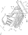
- FIG. 1 illustrates a perspective view of one embodiment of a work vehicle 10.
- the work vehicle 10 is configured as a crawler dozer.
- the work vehicle 10 extends longitudinally (e.g., as indicated by arrow 12 in FIG. 1 ) between a forward end 14 of the work vehicle 10 and an aft end 16 of the work vehicle 10.
- the work vehicle 10 also extends laterally (e.g., as indicated by arrow 18 in FIG. 1 ) between a first side 20 of the work vehicle 10 and a second side 22 of the work vehicle 10.
- the work vehicle 10 may be configured as any other suitable work vehicle known in the art, including those for agricultural and construction applications, transport, sport, and/or the like.
- the work vehicle 10 may include a chassis 24 that is configured to support or couple to a plurality of components.
- the chassis 24 may be configured to support a grading implement 26 at the forward end 14 of the work vehicle 10 and an enclosed operator's cab 28 at the aft end 16 of the work vehicle 10.
- a first track assembly 30 may be coupled to the chassis 24 on the first side 20 of the work vehicle 10
- a second track assembly 32 may be coupled to the chassis 24 on the second side 22 of the work vehicle 10.
- the chassis 24 may be configured to support or couple to any suitable work vehicle component or configuration of vehicle components.
- the grading implement 26 may be configured to remove a layer of soil from a current soil surface or otherwise move a volume of soil relative to the current soil surface.
- the grading implement 26 may be configured as a blade.
- the grading implement 26 may be configured to be adjustably mounted to the chassis 24 so as to control the layer of soil removed from the current soil surface by the grading implement 26.
- the grading implement 26 may be adjustably coupled to the chassis 24 by a pair of pivot arms 34, 36.
- the work vehicle 10 may include one or more actuators 38, which are configured to adjust a depth of the grading implement 26 by moving the arms 34, 36 relative to the chassis 24.
- the work vehicle 10 may include one or more actuators 40, which are configured to adjust the angle of the grading implement 26 by moving the grading implement 26 relative to the pivot arms 34, 36.
- the grading implement 26 may be configured as any suitable type of grading implement, such as a bucket.
- the grading implement 26 may be coupled to the chassis 24 in any suitable manner.
- the track assemblies 30, 32 of the work vehicle 10 may be configured to move the work vehicle 10 relative to the current soil surface.
- the track assemblies 30, 32 may be configured to move the work vehicle 10 in a forward direction (e.g., as indicated by arrow 42 in FIG. 1 ) where the grading implement 26 traverses the current soil surface prior to the aft end 16 of the work vehicle 10.
- the track assemblies 30, 32 may be configured to move the work vehicle 10 in a reverse direction (e.g., as indicated by arrow 44 in FIG. 1 ) where aft end 16 of the work vehicle 10 traverses the current soil surface prior to the grading implement 26.
- the work vehicle 10 may be moved by wheel/tire assemblies (not shown) in addition to or in lieu of the track assemblies 30, 32.
- the configuration of the work vehicle 10 described above and shown in FIG. 1 is provided only to place the present subject matter in an exemplary field of use.
- the present subject matter may be readily adaptable to any manner of work vehicle configuration.
- the work vehicle 10 may include an open operator's cab 18.
- FIG. 2 a schematic view of one embodiment of a system 100 for creating a final graded soil surface having a final soil depth relative to an initial ungraded soil surface is illustrated in accordance with aspects of the present subject matter.
- the system 100 will be described herein with reference to the work vehicle 10 described above with reference to FIG. 1 .
- the disclosed system 100 may generally be utilized with work vehicles having any other suitable work vehicle configuration.
- the system 100 may include one or more components of the work vehicle 10.
- the system 100 may include the pivot arms 34, 36, which, as indicated above, may be configured to be pivotable or otherwise moveable relative to the chassis 24 of the work vehicle 10 to permit the actuator(s) 38 to adjust the position of the arms 34, 36 relative to the chassis 24 and the actuator(s) 38.
- one end of each actuator 38 may be pivotably coupled to the chassis 24 at a pivot joint 46.
- an opposed end of each actuator 38 may also be coupled to the associated pivot arm 34, 36 at a pivot joint 48.
- Each pivot arm 34, 36, which may support the grading implement 26, may, in turn, be coupled to the chassis 24 at a pivot joint 50.
- pivot joints 46, 48, 50 may allow relative pivotable movement between the chassis 24, the pivot arms 34, 36, and the actuator(s) 38, thereby allowing the position of the pivot arms 34, 36 relative to the chassis 24 to be adjusted.
- the pivot arms 34, 36 may be adjustably coupled to the chassis 24 in any suitable manner that permits the actuator(s) 38 to move the arms 34, 36 relative to the chassis 24.
- each actuator 38 may, for example, correspond to a fluid-driven actuator, such as a hydraulic actuator or a pneumatic actuator.
- each actuator 38 may include a cylinder 52 configured to house a piston 54 and a rod 56 coupled to the piston 54 that extends outwardly from the cylinder 52.
- each actuator 38 may include a cap-side chamber 58 and a rod-side chamber 60 defined within the cylinder 52.
- the actuation of the rod 56 may be controlled. As shown in FIG.
- the end of the rod 56 is coupled to the associated pivot arm 34, 36 at the pivot joint 48 while the cylinder 52 is coupled to the chassis 24 at the opposed pivot joint 46.
- the end of the rod 56 may be coupled to the chassis 24 at the pivot joint 46 while the cylinder 52 may be coupled to the associated pivot arm 34, 36 at the pivot joint 48.
- the actuator 38 may be any suitable type of actuator.
- the system 100 may also include a suitable pressure regulating valve 102 (PRV) (e.g., a solenoid-activated valve or a manually operated valve) configured to regulate a supply of fluid (e.g., hydraulic fluid or air from a suitable fluid source or tank 104) being supplied to each actuator 38.
- PRV pressure regulating valve
- the PRV 102 may be in fluid communication with the rod-side chamber 60 of the associated actuator 38.
- the system 100 may include a fluid conduit 106, such as the illustrated hose, that fluidly couples the PRV 102 to a fitting 108 on the associated cylinder 52.
- the PRV 102 may regulate the supply fluid to the associated rod-side chamber 60.
- the PRV 102 may be in fluid communication with the associated piston-side chamber 58 to regulate the supply fluid thereto.
- the system 100 may include a pair of PRVs 102 associated with each actuator 38, with each PRV 102 being in fluid communication with one of the chambers 58, 60 of the associated actuator 38.
- the system 100 may also include the vehicle's grading implement 26, which may be configured to be pivotable or otherwise moveable relative to the pivot arms 34, 36 of the work vehicle 10 to permit the actuator(s) 40 to adjust the position of the grading implement 26 relative to the arms 34, 36.
- the vehicle's grading implement 26 may be configured to be pivotable or otherwise moveable relative to the pivot arms 34, 36 of the work vehicle 10 to permit the actuator(s) 40 to adjust the position of the grading implement 26 relative to the arms 34, 36.
- one end of each actuator 40 may be pivotably coupled to the associated pivot arm 34, 36 at a pivot joint 62.
- an opposed end of each actuator 40 may be coupled to the grading implement 26 at a pivot joint 64.
- the grading implement 26 may, in turn, be coupled to the associated pivot arm 34, 36 at a pivot joint 66.
- the pivot joints 62, 64, 66 may allow relative pivotable movement between the grading implement 26, the pivot arms 34, 36, and the actuator(s) 40, thereby allowing the position of the grading implement 26 relative to the arms 34, 36 to be adjusted.
- the grading implement 26 may be adjustably coupled to the arms 34, 36 in any suitable manner that permits the actuator(s) 40 to move the grading implement 26 relative to the arms 34, 36.
- each actuator 40 may, for example, correspond to a fluid-driven actuator, such as a hydraulic actuator or a pneumatic actuator.
- each actuator 40 may include a cylinder 68 configured to house a piston 70 and a rod 72 coupled to the piston 70 that extends outwardly from the cylinder 68.
- each actuator 40 may include a cap-side chamber 74 and a rod-side chamber 76 defined within the cylinder 68. As is generally understood, by regulating the pressure of the fluid supplied to one or both of the cylinder chambers 74, 76, the actuation of the rod 72 may be controlled. As shown in FIG.
- the end of the rod 72 is coupled to the grading implement 26 at the pivot joint 64 while the cylinder 68 is coupled to the associated arm 34, 36 at the opposed pivot joint 62.
- the end of the rod 72 may be coupled to the associated arm 34, 36 at the pivot joint 62 while the cylinder 68 may be coupled to the grading implement 26 at the pivot joint 64.
- the actuator(s) 40 may be any suitable type of actuator.
- the system 100 may also include a suitable pressure regulating valve 110 (PRV) (e.g., a solenoid-activated valve or a manually operated valve) configured to regulate a supply of fluid (e.g., hydraulic fluid or air from the fluid source or tank 104) being supplied to each actuator 40.
- PRV pressure regulating valve
- the PRV 110 may be in fluid communication with the rod-side chamber 76 of the associated actuator 40.
- the system 100 may include a fluid conduit 112, such as the illustrated hose, that fluidly couples the PRV 110 to a fitting 114 on the associated cylinder 68.
- the PRV 110 may regulate the supply fluid to the associated rod-side chamber 76.
- the PRV 110 may be in fluid communication with the associated piston-side chamber 74 to regulate the supply fluid thereto.
- the system 100 may include a pair of PRVs 110 associated with each actuator 40, with each PRV 110 being in fluid communication with one of the chambers 74, 76 of the associated actuator 40.
- the system 100 may also include a sensor 116 configured to detect a parameter indicative of a current soil depth 118 of a current soil surface 120 relative to an initial ungraded soil surface 122.
- the initial ungraded soil surface 122 refers to the soil surface before grading operations have been performed thereon, such as grading operations in accordance with method 200 described below with reference to FIG. 7 .
- the sensor 116 may correspond to any suitable sensor(s) or sensing device(s) that is configured to directly or indirectly detect the current soil depth 118.
- the sensor 116 may be provided in operative association with the grading implement 26.
- the senor 116 may correspond to a LIDAR sensor coupled to the grading implement 26.
- the sensor 102 may be configured to detect a vertical position differential between the grading implement 26 and a fixed point elevation, which may be indicative of the current soil depth 118.
- the sensor 116 may correspond to any other suitable sensor(s) or sensing device(s) configured to detect the current soil depth.
- the system 100 may further include a controller 124 configured to electronically control the operation of one or more components of the work vehicle 10.
- the controller 124 may comprise any suitable processor-based device known in the art, such as a computing device or any suitable combination of computing devices.
- the controller 124 may include one or more processor(s) 126 and associated memory device(s) 128 configured to perform a variety of computer-implemented functions.
- processor refers not only to integrated circuits referred to in the art as being included in a computer, but also refers to a controller, a microcontroller, a microcomputer, a programmable logic controller (PLC), an application specific integrated circuit, and other programmable circuits.
- PLC programmable logic controller
- the memory device(s) 128 of the controller 124 may generally comprise memory element(s) including, but not limited to, a computer readable medium (e.g., random access memory (RAM)), a computer readable non-volatile medium (e.g., a flash memory), a floppy disk, a compact disc-read only memory (CD-ROM), a magneto-optical disk (MOD), a digital versatile disc (DVD) and/or other suitable memory elements.
- RAM random access memory
- a computer readable non-volatile medium e.g., a flash memory
- CD-ROM compact disc-read only memory
- MOD magneto-optical disk
- DVD digital versatile disc
- Such memory device(s) 128 may generally be configured to store suitable computer-readable instructions that, when implemented by the processor(s) 126, configure the controller 124 to perform various computer-implemented functions, such as one or more aspects of the methods 200 described below with reference to FIG. 7 .
- the controller 124 may also include various other
- controller 124 may correspond to an existing controller of the work vehicle 10 or the controller 124 may correspond to a separate processing device.
- the controller 124 may form all or part of a separate plug-in module that may be installed within the work vehicle 10 to allow for the disclosed system and method to be implemented without requiring additional software to be uploaded onto existing control devices of the work vehicle 10.
- the system 100 may not include the sensor 116 for detecting a parameter indicative of a current soil depth 118.
- the system 100 may include a user interface 130 that is configured to receive an input from an operator of the work vehicle 10, such as an input associated with the current soil depth.
- the user interface 130 may include one or more input devices (not shown), such as touchscreens, keypads, touchpads, knobs, buttons, sliders, switches, mice, microphones, and/or the like, which are configured to receive user inputs from the operator.
- the user interface 130 may include one or more feedback devices (not shown), such as display screens, speakers, warning lights, and/or the like, which are configured to communicate the feedback, such as feedback from the controller 124, to the operator of the work vehicle 10.
- the user interface 130 may have any suitable configuration.
- the system 100 may include both the sensor 116 and the user interface 130.
- the controller 124 may be configured to control an operation of the grading implement 26 of the work vehicle 10 such that the grading implement 26 removes a layer of soil from a current soil surface 120 as the work vehicle 10 is moved in the forward direction 42.
- the controller 124 may be communicatively coupled to the various components of the work vehicle 10 and/or the system 100, such as the PRVs 102, 110.
- the controller 104 may be configured to control the depth and/or angle of the grading implement 26 such that the grading implement 26 removes a layer of soil of a desired thickness from the current soil surface 120.
- the controller 124 may be configured to transmit suitable control signals (e.g., as indicated by dashed lines 132, 134 in FIGS. 2 , 3 , 5 , and 6 ) to the PRVs 102, 110 such that PRVs 102, 110 regulate the volume of fluid within the chambers 58, 60, 74, 76 of the actuators 38, 40 so as to position the grading implement 26 at the desired angle relative to the arms 34, 26 and/or at the desired depth relative to the chassis 24.
- the grading implement 26 is shown in FIGS. 2 and 3 as removing a layer of soil from the initial ungraded soil surface 122, which, in the instance shown, corresponds to the current soil surface 120. It should be appreciated that the controller 124 may be configured to control the grading implement 26 while the work vehicle 10 is moved over the current soil surface 120 in the forward direction 42 several times.
- the controller 124 may be configured to control the grading implement 26 to remove soil from the current soil surface 120 based on a selected offset soil depth (such as a first offset soil depth 136 or a second offset soil depth 138).
- the grading implement 26 may be used to remove soil from the current soil surface 120 while the work vehicle 10 is moved in the forward direction 42 until the current soil surface 120 is at the offset soil depth 136, 138.
- the offset soil depth 136, 138 differs from a desired final soil depth 140 of a final graded soil surface 142.
- the final graded soil surface 142 refers to soil surface after all grading operations, such as grading operations in accordance with method 200 described below with reference to FIG.
- the first offset soil depth 136 is less than the final soil depth 140. That is, an offset soil surface 144 at the first offset soil depth 136 is shallower relative to the initial ungraded soil surface 122 than the final graded soil surface 142.
- the second offset soil depth 138 is greater than the final soil depth 140. That is, an offset soil surface 146 at the second offset soil depth 138 is deeper relative to the initial ungraded soil surface 122 than the final graded soil surface 142.
- the system 100 may be configured to determine when the current soil surface 120 is at the selected or desired offset soil depth 136, 138.
- controller 124 may be communicatively coupled to the sensor 116 via a wired or wireless connection to allow measurement signals (e.g., indicated by dashed lines 148 in FIGS. 2 , 5 , and 6 ) to be transmitted from the sensor 116 to the controller 124.
- the controller 124 may then be configured monitor the current soil depth 118 of the current soil surface 120 relative to the initial ungraded soil surface 122 based on the measurement signals 148 received from the sensor 116.
- the controller 124 may include a look-up table or suitable mathematical formula stored within its memory 128 that correlates the sensor measurements to the current soil depth 118 of the current soil surface 120.
- the controller 124 may be configured to compare the current soil depth 118 to the selected offset soil depth 136, 138 to determine when the current soil depth 118 is the same as the offset soil depth 136, 138.
- the controller 124 may be configured to notify the operator of the work vehicle 10 when the current soil surface 120 is at the selected offset soil depth 136, 138, such as via a visual and/or an audible notification through the user interface 130.
- the controller 124 may be communicatively coupled to the user interface 130 via a wired or wireless connection to allow user input signals (e.g., indicated by dashed line 150 in FIG. 3 ) to be transmitted from the user interface 130 to the controller 124.
- the controller 124 may configured to receive a notification from the operator of the work vehicle 10 when the current soil surface 120 is at the selected offset soil depth 136, 138.
- the controller 124 may be configured to control the grading implement 26 to remove soil from the current soil surface 120 while the work vehicle 10 is moved in the forward direction 42 based on a soil topography map 152.
- the selected offset soil depth 136, 138 may vary with geographical position.
- the soil topography map 152 may correlate the offset soil depth 136, 138 to a geographical position or location.
- the controller 124 may be configured to control the depth and/or angle of the grading implement 26 so as to form the offset surface 144, 146 having the desired geographical topography.
- the soil topography map 152 may be stored in the memory device 128 of the controller 124.
- the system 100 may include a GPS receiver configured to monitor the geographical location of the work vehicle 10.
- the soil topography map 152 may show the geographical correlation between the initial ungraded soil surface 122, the current soil surface 120, the final graded soil surface 142, and the offset soil surface 146.
- the controller 124 may be configured to update the soil topography map 152 based on changes in the current soil surface 120.
- the controller 124 may be configured to update the soil topography map 152 to show the current soil surface 120 as being closer to the first offset soil surface 136 as the grading implement 26 removes successive layers of soil.
- the soil topography map 152 may only show the geographical variation of some of the initial ungraded soil surface 122, the current soil surface 120, the final graded soil surface 142, and the offset soil surface 146. Furthermore, the soil topography map 152 may show the geographical variation of additional parameters. In addition, although FIG. 4 illustrates the soil topography map 152 as a two dimensional map, the soil topography map 152 may be a three dimensional map.
- the controller 124 may be configured to store a plurality of preselected first offset soil depths 136 and/or second offset soil depth 138 (e.g., in the memory device(s) 128). As such, when the operator of the work vehicle 10 selects one of the preselected offset depths 136, 138, the controller 124 may be configured to control the position of the grading implement 26 so as to remove soil from the current soil surface 120 until the offset soil surface 144, 146 is at the selected preselected offset depth 136, 138.
- each preselected offset depth 136 may correspond to a desired thickness of loose soil on the final graded soil surface 142 for planting different types of grass (e.g., rye, fescue, etc.).
- the preselected offset depths 136, 138 may be based on any suitable criteria.
- the preselected offset depths 136, 138 may be stored in derived from field data and imported into the controller 124. As such, in one embodiment, the preselected offset depths 136, 138 may be imported into the controller 124 as part of the soil topography map 152 or when the soil topography map 152 is being imported.
- controller 124 may be configured to store a preselected offset depth 136, 138 provided by the operator during operation of the work vehicle 10 (e.g., the user interface 130). Such operator-provided preselected offset depth 136, 138 may be based on a commonly repeated offset depth 136, 138 that is not already stored within the controller 124.
- the controller 124 may be configured to control the position of the grading implement 26 so as to remove soil based on a depth differential 154 defined between the first offset soil depth 136 and the final soil depth 140 to create the final graded soil surface 142 as the work vehicle 10 is moved in the reverse direction 44.
- the controller 124 may be configured to control the depth and/or angle of the grading implement 26 so as to remove a layer of soil from the offset soil surface 144 corresponding to the depth differential 154 while the work vehicle 10 is moved in the reverse direction 44.
- the final graded soil surface 142 When formed by removing a layer of soil from the offset soil surface 144, the final graded soil surface 142 may generally be of a hard, compacted nature that is suitable for constructing buildings and/or roads thereon. Since the grading implement 26 may generally be positioned forward of the track assemblies 30, 32, the grading implement 26 removes any grooves or indentations formed by the track assemblies 30, 32 by forming the final graded soil surface 142 while the work vehicle 10 is moved in the reverse direction 44.
- the controller 124 may be configured to control the position of the grading implement 26 so as to add soil based on a depth differential 156 defined between the second offset soil depth 138 and the final soil depth 140 to create the final graded soil surface 142 as the work vehicle 10 is moved in the reverse direction 44.
- the controller 124 may be configured to control the depth and/or angle of the grading implement 26 so as to add a layer of soil to the offset soil surface 146 corresponding to the depth differential 146 while the work vehicle 10 is moved in the reverse direction 44.
- the grading implement 26 may spread a volume of soil 158 onto the offset soil surface 146.
- the final graded soil surface 142 may generally be of a loose, non-compacted nature that is suitable for planting grass or other vegetation thereon. Since the grading implement 26 may generally be positioned forward of the track assemblies 30, 32, the grading implement 26 removes any grooves or indentations formed by the track assemblies 30, 32 by forming the final graded soil surface 142 while the work vehicle 10 is moved in the reverse direction 44.
- FIG. 7 a flow diagram of one embodiment of a method 200 for creating a final graded soil surface having a final soil depth relative to an initial ungraded soil surface is illustrated in accordance with aspects of the present subject matter.
- the method 200 will be described herein with reference to the work vehicle 10 and the system 100 described above with reference to FIGS. 1-6 .
- the disclosed method 200 may generally be utilized to create a final graded soil surface with any work vehicle having any suitable work vehicle configuration.
- FIG. 7 depicts steps performed in a particular order for purposes of illustration and discussion, the methods discussed herein are not limited to any particular order or arrangement.
- steps of the methods disclosed herein can be omitted, rearranged, combined, and/or adapted in various ways without deviating from the scope of the present disclosure.
- the method 200 may include controlling an operation of a grading implement of a work vehicle such that the grading implement removes a layer of soil from a current soil surface as the work vehicle is moved in a forward direction.
- the controller 124 may be configured to control the operation of the grading implement 26 of the work vehicle 10 such that the grading implement 26 removes a layer of soil from a current soil surface 120 as the work vehicle 10 is moved in a forward direction 42.
- the controller 124 may be configured to control the depth and/or angle of the grading implement 26 so as to remove soil from the current soil surface 120 while the work vehicle 10 is moved in the forward direction 42 until the current soil surface 120 is at the offset soil depth 136, 138.
- the method 200 may include receiving an input indicative of the current soil surface being at an offset soil depth relative to the initial ungraded soil surface.
- the controller 124 may be configure to monitor the current soil depth 118 of the current soil surface 120 based on the measurement signals 148 received from the sensor 116 and determine when the current soil depth 118 is the same as the offset soil depth 136, 138.
- the controller 124 may be configured to receive a notification from an operator of the work vehicle 10, such as via user the input signals 150 transmitted from the user interface 130, when the current soil surface 120 is at the offset soil depth 136, 138.
- the method 200 may include adjusting a position of the grading implement so as to add or remove soil based on a depth differential defined between the offset soil depth and the final soil depth to create the final graded soil surface as the work vehicle is moved in the reverse direction when the current soil surface is at the offset soil depth.
- the controller 124 may be configured to adjust the position of the grading implement 26 to remove soil to the offset soil surface 144 based on the depth differential 154 defined between the first offset soil depth 136 and the final soil depth 140 so as to create the final graded soil surface 142 as the work vehicle 10 is moved in the reverse direction 44.
- the controller 124 may be configured to adjust the position of the grading implement 26 to add soil to the second offset soil surface 146 based on a depth differential 156 defined between the second offset soil depth 138 and the final soil depth 140 to create the final graded soil surface 142 as the work vehicle 10 is moved in the reverse direction 44.
Landscapes
- Engineering & Computer Science (AREA)
- Mining & Mineral Resources (AREA)
- Civil Engineering (AREA)
- General Engineering & Computer Science (AREA)
- Structural Engineering (AREA)
- Mechanical Engineering (AREA)
- Operation Control Of Excavators (AREA)
- Soil Working Implements (AREA)
Abstract
Description
- The present disclosure generally relates to work vehicles and, more particularly, to methods and systems for using work vehicles to create a final graded soil surface having a final soil depth relative an initial ungraded soil surface by adding or removing soil to a current soil surface when the current soil surface is at an offset soil depth that differs from the final soil depth.
- It is well known that, in the construction of many buildings, bridges, roads, and/or the like, that the topography of the soil must be manipulated, typically through the use a grading operation. Grading operations are generally performed by a work vehicle, such as a crawler dozer, that includes a grading implement, such as a blade, configured to remove a layer of soil from a current soil surface. The work vehicle typically includes a pair of tracks for use in traversing the current soil surface.
- The grading implement is generally located at a forward end of the work vehicle so as to push a layer of soil in front of the work vehicle as the work vehicle is moved in a forward direction. However, considering the large size and weight of many work vehicles configured to perform grading operations, the tracks of such work vehicles may leave grooves or other indentions in the final graded surface. As such, it is necessary to use smaller, lighter work vehicles to remove the grooves or indentions, which increases the time and cost of the construction project.
- Accordingly, an improved method and system for creating a final graded soil surface having a final soil depth relative an initial ungraded soil surface would be welcomed in the technology.
- Aspects and advantages of the technology will be set forth in part in the following description, or may be obvious from the description, or may be learned through practice of the technology.
- In one aspect, the present subject matter is directed to a method for creating a final graded soil surface having a final soil depth relative to an initial ungraded soil surface. The method may include controlling, with a computing device, an operation of a grading implement of a work vehicle such that the grading implement removes a layer of soil from a current soil surface as the work vehicle is moved in a forward direction. The work vehicle may extend longitudinally between a forward end and an aft end. The grading implement may be located at the forward end of the work vehicle. The grading implement may traverse the current soil surface prior to the aft end of the work vehicle when work vehicle is moved in the forward direction. The aft end of the work vehicle may traverse the current soil surface prior to the grading implement when work vehicle is moved in a reverse direction. The method may also include receiving, with the computing device, an input indicative of the current soil surface being at an offset soil depth relative to the initial ungraded soil surface, with the offset soil depth differing from the final soil depth. When the current soil surface is at the offset soil depth, the method may further include adjusting, with the computing device, a position of the grading implement so as to add or remove soil based on a depth differential defined between the offset soil depth and the final soil depth to create the final graded soil surface as the work vehicle is moved in the reverse direction.
- In another aspect, the present subject matter is directed to a system for creating a final graded soil surface having a final soil depth relative to an initial ungraded soil surface. The system may include a work vehicle extending longitudinally between a forward end and an aft end. The work vehicle may include a grading implement positioned at the forward end of the work vehicle. The work vehicle may be configured to be moved in both a forward direction and a reverse direction. The grading implement may traverse a current soil surface prior to the aft end of the work vehicle when the work vehicle moves in the forward direction. The aft end of the work vehicle may traverse the current soil surface prior to the grading implement when the work vehicle moves in the reverse direction. The system may also include a controller communicatively coupled to the work vehicle. The controller may be configured to position the grading implement at an offset soil depth relative to the initial ungraded soil surface such that the current soil surface is graded to the offset soil depth as the work vehicle is moved in the forward direction across the soil surface, with the offset soil depth differing from the final soil depth. When the current soil surface is at the offset soil depth, the controller may be configured to adjust the position of the grading implement so as to add or remove soil based on a depth differential defined between the offset soil depth and the final soil depth to create the final graded soil surface as the work vehicle is moved in the reverse direction across the soil surface.
- These and other features, aspects and advantages of the present technology will become better understood with reference to the following description and appended claims. The accompanying drawings, which are incorporated in and constitute a part of this specification, illustrate embodiments of the technology and, together with the description, serve to explain the principles of the technology.
- A full and enabling disclosure of the present technology, including the best mode thereof, directed to one of ordinary skill in the art, is set forth in the specification, which makes reference to the appended figures, in which:
-
FIG. 1 illustrates a perspective view of one embodiment of a work vehicle in accordance with aspects of the present subject matter; -
FIG. 2 illustrates a schematic view of one embodiment of a system for creating a final graded soil surface having a final soil depth relative to an initial ungraded soil surface in accordance with aspects of the present subject matter, particularly illustrating the system including a sensor for detecting a parameter associated with a current soil depth of a current soil surface; -
FIG. 3 illustrates a schematic view of a further embodiment of a system for creating a final graded soil surface having a final soil depth relative to an initial ungraded soil surface in accordance with aspects of the present subject matter, particularly illustrating the system including a user interface for receiving a notification when a current soil surface is at an offset soil depth relative to the initial ungraded soil surface; -
FIG. 4 illustrates a graphical view of an example soil topography map charting a geographical distribution of a current soil depth of a current soil surface, an offset soil depth of an offset soil surface, and a final soil depth of a final graded surface relative to an initial ungraded soil surface in accordance with aspects of the present subject matter; -
FIG. 5 illustrates a schematic view of the embodiment of the system shown inFIG. 2 , particularly illustrating the system being configured to control a grading implement to remove soil to create the final graded soil surface when an offset soil depth is less than the final soil depth; -
FIG. 6 illustrates a schematic view of the embodiment of the system shown inFIG. 2 , particularly illustrating the system being configured to control a grading implement to add soil to create the final graded soil surface when an offset soil depth is greater than the final soil depth; and -
FIG. 7 illustrates a flow diagram of one embodiment of a method for creating a final graded soil surface having a final soil depth relative to an initial ungraded soil surface in accordance with aspects of the present subject matter. - Repeat use of reference characters in the present specification and drawings is intended to represent the same or analogous features or elements of the present technology.
- Reference now will be made in detail to embodiments of the invention, one or more examples of which are illustrated in the drawings. Each example is provided by way of explanation of the invention, not limitation of the invention. In fact, it will be apparent to those skilled in the art that various modifications and variations can be made in the present invention without departing from the scope or spirit of the invention. For instance, features illustrated or described as part of one embodiment can be used with another embodiment to yield a still further embodiment. Thus, it is intended that the present invention covers such modifications and variations as come within the scope of the appended claims and their equivalents.
- In general, the present subject matter is directed to methods and systems for creating a final graded soil surface having a final soil depth relative to an initial ungraded soil surface. Specifically, in several embodiments, a controller may be configured to control an operation of a grading implement of a work vehicle such that the grading implement removes a layer of soil from a current soil surface as the work vehicle is moved in a forward direction. The controller may also be configured to receive an input indicative of the current soil surface being at an offset soil depth relative to the initial ungraded soil surface that differs from the desired final soil depth, such as an input from a sensor or an operator of the work vehicle. When the current soil surface is at the offset soil depth, the controller may be configured to adjust a position of the grading implement so as to add or remove soil based on a depth differential defined between the offset soil depth and the desired final soil depth to create the final graded soil surface as the work vehicle is moved in a reverse direction. For example, in one embodiment, when the offset depth is greater than the final soil depth, the controller may be configured to control a depth and/or angle of the grading implement so as to add soil to create the final graded soil surface as the work vehicle is moved back across the previously graded surface in the reverse direction. Similarly, when the offset depth is less than the final soil depth, the controller may be configured to control a depth and/or angle of the grading implement so as to remove soil to create the final graded soil surface as the work vehicle is moved back across the previously graded surface in the reverse direction. Creating the final grade soil surface by adding or removing soil while the work vehicle is moved in the reverse direction may prevent the formation of any grooves or indentions in the final grade soil surface by tracks or wheels of the work vehicle.
- Referring now to the drawings,
FIG. 1 illustrates a perspective view of one embodiment of awork vehicle 10. As shown, thework vehicle 10 is configured as a crawler dozer. In general, thework vehicle 10 extends longitudinally (e.g., as indicated byarrow 12 inFIG. 1 ) between aforward end 14 of thework vehicle 10 and anaft end 16 of thework vehicle 10. In addition, thework vehicle 10 also extends laterally (e.g., as indicated byarrow 18 inFIG. 1 ) between afirst side 20 of thework vehicle 10 and asecond side 22 of thework vehicle 10. However, in other embodiments, thework vehicle 10 may be configured as any other suitable work vehicle known in the art, including those for agricultural and construction applications, transport, sport, and/or the like. - As shown in
FIG. 1 , thework vehicle 10 may include achassis 24 that is configured to support or couple to a plurality of components. For example, in one embodiment, thechassis 24 may be configured to support agrading implement 26 at theforward end 14 of thework vehicle 10 and an enclosed operator'scab 28 at theaft end 16 of thework vehicle 10. Additionally, afirst track assembly 30 may be coupled to thechassis 24 on thefirst side 20 of thework vehicle 10, and asecond track assembly 32 may be coupled to thechassis 24 on thesecond side 22 of thework vehicle 10. However, it should be appreciated that thechassis 24 may be configured to support or couple to any suitable work vehicle component or configuration of vehicle components. - In accordance with aspects of the present disclosure, the
grading implement 26 may be configured to remove a layer of soil from a current soil surface or otherwise move a volume of soil relative to the current soil surface. As shown, thegrading implement 26 may be configured as a blade. In several embodiments, the grading implement 26 may be configured to be adjustably mounted to thechassis 24 so as to control the layer of soil removed from the current soil surface by the grading implement 26. For example, as shown, in one embodiment, the grading implement 26 may be adjustably coupled to thechassis 24 by a pair ofpivot arms work vehicle 10 may include one ormore actuators 38, which are configured to adjust a depth of the grading implement 26 by moving thearms chassis 24. In addition, thework vehicle 10 may include one ormore actuators 40, which are configured to adjust the angle of the grading implement 26 by moving the grading implement 26 relative to thepivot arms chassis 24 in any suitable manner. - In several embodiments, the
track assemblies work vehicle 10 may be configured to move thework vehicle 10 relative to the current soil surface. For example, thetrack assemblies work vehicle 10 in a forward direction (e.g., as indicated byarrow 42 inFIG. 1 ) where the grading implement 26 traverses the current soil surface prior to theaft end 16 of thework vehicle 10. Similarly, thetrack assemblies work vehicle 10 in a reverse direction (e.g., as indicated byarrow 44 inFIG. 1 ) whereaft end 16 of thework vehicle 10 traverses the current soil surface prior to the grading implement 26. It should be appreciated that, in some embodiments, thework vehicle 10 may be moved by wheel/tire assemblies (not shown) in addition to or in lieu of thetrack assemblies - It should be appreciated that the configuration of the
work vehicle 10 described above and shown inFIG. 1 is provided only to place the present subject matter in an exemplary field of use. Thus, it should be apparent that the present subject matter may be readily adaptable to any manner of work vehicle configuration. For example, in an alternative embodiment, thework vehicle 10 may include an open operator'scab 18. - Referring now to
FIG. 2 , a schematic view of one embodiment of a system 100 for creating a final graded soil surface having a final soil depth relative to an initial ungraded soil surface is illustrated in accordance with aspects of the present subject matter. In general, the system 100 will be described herein with reference to thework vehicle 10 described above with reference toFIG. 1 . However, it should be appreciated by those of ordinary skill in the art that the disclosed system 100 may generally be utilized with work vehicles having any other suitable work vehicle configuration. - As shown in
FIG. 2 , the system 100 may include one or more components of thework vehicle 10. For example, the system 100 may include thepivot arms chassis 24 of thework vehicle 10 to permit the actuator(s) 38 to adjust the position of thearms chassis 24 and the actuator(s) 38. For example, in one embodiment, one end of each actuator 38 may be pivotably coupled to thechassis 24 at a pivot joint 46. Similarly, an opposed end of each actuator 38 may also be coupled to the associatedpivot arm pivot arm chassis 24 at a pivot joint 50. As such, the pivot joints 46, 48, 50 may allow relative pivotable movement between thechassis 24, thepivot arms pivot arms chassis 24 to be adjusted. However, a person of ordinary skill in the art would appreciate that thepivot arms chassis 24 in any suitable manner that permits the actuator(s) 38 to move thearms chassis 24. - As shown, each actuator 38 may, for example, correspond to a fluid-driven actuator, such as a hydraulic actuator or a pneumatic actuator. Thus, in several embodiments, each actuator 38 may include a
cylinder 52 configured to house apiston 54 and arod 56 coupled to thepiston 54 that extends outwardly from thecylinder 52. Additionally, each actuator 38 may include a cap-side chamber 58 and a rod-side chamber 60 defined within thecylinder 52. As is generally understood, by regulating the pressure of the fluid supplied to one or both of thecylinder chambers rod 56 may be controlled. As shown inFIG. 2 , in the illustrated embodiment, the end of therod 56 is coupled to the associatedpivot arm cylinder 52 is coupled to thechassis 24 at the opposed pivot joint 46. However, in an alternative embodiment, the end of therod 56 may be coupled to thechassis 24 at the pivot joint 46 while thecylinder 52 may be coupled to the associatedpivot arm actuator 38 may be any suitable type of actuator. - In several embodiments, the system 100 may also include a suitable pressure regulating valve 102 (PRV) (e.g., a solenoid-activated valve or a manually operated valve) configured to regulate a supply of fluid (e.g., hydraulic fluid or air from a suitable fluid source or tank 104) being supplied to each
actuator 38. As shown inFIG. 2 , in one embodiment, thePRV 102 may be in fluid communication with the rod-side chamber 60 of the associatedactuator 38. In this respect, the system 100 may include afluid conduit 106, such as the illustrated hose, that fluidly couples thePRV 102 to a fitting 108 on the associatedcylinder 52. As such, thePRV 102 may regulate the supply fluid to the associated rod-side chamber 60. It should be appreciated that, in alternate embodiments, thePRV 102 may be in fluid communication with the associated piston-side chamber 58 to regulate the supply fluid thereto. Alternatively, the system 100 may include a pair ofPRVs 102 associated with each actuator 38, with eachPRV 102 being in fluid communication with one of thechambers actuator 38. - The system 100 may also include the vehicle's grading implement 26, which may be configured to be pivotable or otherwise moveable relative to the
pivot arms work vehicle 10 to permit the actuator(s) 40 to adjust the position of the grading implement 26 relative to thearms pivot arm pivot arm pivot arms arms arms arms - As shown, each actuator 40 may, for example, correspond to a fluid-driven actuator, such as a hydraulic actuator or a pneumatic actuator. Thus, in several embodiments, each actuator 40 may include a
cylinder 68 configured to house apiston 70 and arod 72 coupled to thepiston 70 that extends outwardly from thecylinder 68. Additionally, each actuator 40 may include a cap-side chamber 74 and a rod-side chamber 76 defined within thecylinder 68. As is generally understood, by regulating the pressure of the fluid supplied to one or both of thecylinder chambers rod 72 may be controlled. As shown inFIG. 2 , in the illustrated embodiment, the end of therod 72 is coupled to the grading implement 26 at the pivot joint 64 while thecylinder 68 is coupled to the associatedarm rod 72 may be coupled to the associatedarm cylinder 68 may be coupled to the grading implement 26 at the pivot joint 64. It should be appreciated that the actuator(s) 40 may be any suitable type of actuator. - In several embodiments, the system 100 may also include a suitable pressure regulating valve 110 (PRV) (e.g., a solenoid-activated valve or a manually operated valve) configured to regulate a supply of fluid (e.g., hydraulic fluid or air from the fluid source or tank 104) being supplied to each
actuator 40. As shown inFIG. 2 , in one embodiment, thePRV 110 may be in fluid communication with the rod-side chamber 76 of the associatedactuator 40. In this respect, the system 100 may include afluid conduit 112, such as the illustrated hose, that fluidly couples thePRV 110 to a fitting 114 on the associatedcylinder 68. As such, thePRV 110 may regulate the supply fluid to the associated rod-side chamber 76. It should be appreciated that, in alternate embodiments, thePRV 110 may be in fluid communication with the associated piston-side chamber 74 to regulate the supply fluid thereto. Alternatively, the system 100 may include a pair ofPRVs 110 associated with each actuator 40, with eachPRV 110 being in fluid communication with one of thechambers actuator 40. - In accordance with aspects of the present disclosure, the system 100 may also include a
sensor 116 configured to detect a parameter indicative of a current soil depth 118 of acurrent soil surface 120 relative to an initialungraded soil surface 122. As used herein, the initialungraded soil surface 122 refers to the soil surface before grading operations have been performed thereon, such as grading operations in accordance withmethod 200 described below with reference toFIG. 7 . In general, thesensor 116 may correspond to any suitable sensor(s) or sensing device(s) that is configured to directly or indirectly detect the current soil depth 118. For example, as shown inFIG. 2 , thesensor 116 may be provided in operative association with the grading implement 26. In such embodiments, thesensor 116 may correspond to a LIDAR sensor coupled to the grading implement 26. In this regard, thesensor 102 may be configured to detect a vertical position differential between the grading implement 26 and a fixed point elevation, which may be indicative of the current soil depth 118. However, it should be appreciated that thesensor 116 may correspond to any other suitable sensor(s) or sensing device(s) configured to detect the current soil depth. - As shown in
FIG. 2 , the system 100 may further include acontroller 124 configured to electronically control the operation of one or more components of thework vehicle 10. In general, thecontroller 124 may comprise any suitable processor-based device known in the art, such as a computing device or any suitable combination of computing devices. Thus, in several embodiments, thecontroller 124 may include one or more processor(s) 126 and associated memory device(s) 128 configured to perform a variety of computer-implemented functions. As used herein, the term "processor" refers not only to integrated circuits referred to in the art as being included in a computer, but also refers to a controller, a microcontroller, a microcomputer, a programmable logic controller (PLC), an application specific integrated circuit, and other programmable circuits. Additionally, the memory device(s) 128 of thecontroller 124 may generally comprise memory element(s) including, but not limited to, a computer readable medium (e.g., random access memory (RAM)), a computer readable non-volatile medium (e.g., a flash memory), a floppy disk, a compact disc-read only memory (CD-ROM), a magneto-optical disk (MOD), a digital versatile disc (DVD) and/or other suitable memory elements. Such memory device(s) 128 may generally be configured to store suitable computer-readable instructions that, when implemented by the processor(s) 126, configure thecontroller 124 to perform various computer-implemented functions, such as one or more aspects of themethods 200 described below with reference toFIG. 7 . In addition, thecontroller 124 may also include various other suitable components, such as a communications circuit or module, one or more input/output channels, a data/control bus and/or the like. - It should be appreciated that the
controller 124 may correspond to an existing controller of thework vehicle 10 or thecontroller 124 may correspond to a separate processing device. For instance, in one embodiment, thecontroller 124 may form all or part of a separate plug-in module that may be installed within thework vehicle 10 to allow for the disclosed system and method to be implemented without requiring additional software to be uploaded onto existing control devices of thework vehicle 10. - Referring now to
FIG. 3 , some embodiments of the system 100 may not include thesensor 116 for detecting a parameter indicative of a current soil depth 118. In such embodiments, the system 100 may include auser interface 130 that is configured to receive an input from an operator of thework vehicle 10, such as an input associated with the current soil depth. As such, theuser interface 130 may include one or more input devices (not shown), such as touchscreens, keypads, touchpads, knobs, buttons, sliders, switches, mice, microphones, and/or the like, which are configured to receive user inputs from the operator. In addition, some embodiments of theuser interface 130 may include one or more feedback devices (not shown), such as display screens, speakers, warning lights, and/or the like, which are configured to communicate the feedback, such as feedback from thecontroller 124, to the operator of thework vehicle 10. However, in alternative embodiments, theuser interface 130 may have any suitable configuration. Furthermore, it should be appreciated that, in some embodiments, the system 100 may include both thesensor 116 and theuser interface 130. - Referring now to
FIGS. 2 and3 , thecontroller 124 may be configured to control an operation of the grading implement 26 of thework vehicle 10 such that the grading implement 26 removes a layer of soil from acurrent soil surface 120 as thework vehicle 10 is moved in theforward direction 42. Specifically, in several embodiments, thecontroller 124 may be communicatively coupled to the various components of thework vehicle 10 and/or the system 100, such as thePRVs work vehicle 10 is moved in theforward direction 42, thecontroller 104 may be configured to control the depth and/or angle of the grading implement 26 such that the grading implement 26 removes a layer of soil of a desired thickness from thecurrent soil surface 120. For example, in one embodiment, thecontroller 124 may be configured to transmit suitable control signals (e.g., as indicated by dashedlines FIGS. 2 ,3 ,5 , and6 ) to thePRVs PRVs chambers actuators arms chassis 24. The grading implement 26 is shown inFIGS. 2 and3 as removing a layer of soil from the initialungraded soil surface 122, which, in the instance shown, corresponds to thecurrent soil surface 120. It should be appreciated that thecontroller 124 may be configured to control the grading implement 26 while thework vehicle 10 is moved over thecurrent soil surface 120 in theforward direction 42 several times. - In several embodiments, the
controller 124 may be configured to control the grading implement 26 to remove soil from thecurrent soil surface 120 based on a selected offset soil depth (such as a first offsetsoil depth 136 or a second offset soil depth 138). In general, the grading implement 26 may be used to remove soil from thecurrent soil surface 120 while thework vehicle 10 is moved in theforward direction 42 until thecurrent soil surface 120 is at the offsetsoil depth soil depth final soil depth 140 of a final gradedsoil surface 142. As used herein, the final gradedsoil surface 142 refers to soil surface after all grading operations, such as grading operations in accordance withmethod 200 described below with reference toFIG. 7 , have been completed. In the illustrated embodiment, the first offsetsoil depth 136 is less than thefinal soil depth 140. That is, an offsetsoil surface 144 at the first offsetsoil depth 136 is shallower relative to the initialungraded soil surface 122 than the final gradedsoil surface 142. Conversely, the second offsetsoil depth 138 is greater than thefinal soil depth 140. That is, an offsetsoil surface 146 at the second offsetsoil depth 138 is deeper relative to the initialungraded soil surface 122 than the final gradedsoil surface 142. - The system 100 may be configured to determine when the
current soil surface 120 is at the selected or desired offsetsoil depth FIG. 2 , in one embodiment,controller 124 may be communicatively coupled to thesensor 116 via a wired or wireless connection to allow measurement signals (e.g., indicated by dashedlines 148 inFIGS. 2 ,5 , and6 ) to be transmitted from thesensor 116 to thecontroller 124. Thecontroller 124 may then be configured monitor the current soil depth 118 of thecurrent soil surface 120 relative to the initialungraded soil surface 122 based on the measurement signals 148 received from thesensor 116. For instance, thecontroller 124 may include a look-up table or suitable mathematical formula stored within itsmemory 128 that correlates the sensor measurements to the current soil depth 118 of thecurrent soil surface 120. In this regard, thecontroller 124 may be configured to compare the current soil depth 118 to the selected offsetsoil depth soil depth controller 124 may be configured to notify the operator of thework vehicle 10 when thecurrent soil surface 120 is at the selected offsetsoil depth user interface 130. - As indicated above, the embodiment of the system 100 shown in
FIG. 3 does not include thesensor 116. In such embodiment, thecontroller 124 may be communicatively coupled to theuser interface 130 via a wired or wireless connection to allow user input signals (e.g., indicated by dashedline 150 inFIG. 3 ) to be transmitted from theuser interface 130 to thecontroller 124. As such, thecontroller 124 may configured to receive a notification from the operator of thework vehicle 10 when thecurrent soil surface 120 is at the selected offsetsoil depth - Referring now to
FIG. 4 , thecontroller 124 may be configured to control the grading implement 26 to remove soil from thecurrent soil surface 120 while thework vehicle 10 is moved in theforward direction 42 based on a soil topography map 152. In certain instances, the selected offsetsoil depth soil depth controller 124 may be configured to control the depth and/or angle of the grading implement 26 so as to form the offsetsurface memory device 128 of thecontroller 124. Furthermore, in some embodiments, the system 100 may include a GPS receiver configured to monitor the geographical location of thework vehicle 10. - An example topography map 152 is shown in
FIG. 4 . Specifically, as shown, in one embodiment, the soil topography map 152 may show the geographical correlation between the initialungraded soil surface 122, thecurrent soil surface 120, the final gradedsoil surface 142, and the offsetsoil surface 146. In one embodiment, thecontroller 124 may be configured to update the soil topography map 152 based on changes in thecurrent soil surface 120. For example, thecontroller 124 may be configured to update the soil topography map 152 to show thecurrent soil surface 120 as being closer to the first offsetsoil surface 136 as the grading implement 26 removes successive layers of soil. It should be appreciated that the soil topography map 152 may only show the geographical variation of some of the initialungraded soil surface 122, thecurrent soil surface 120, the final gradedsoil surface 142, and the offsetsoil surface 146. Furthermore, the soil topography map 152 may show the geographical variation of additional parameters. In addition, althoughFIG. 4 illustrates the soil topography map 152 as a two dimensional map, the soil topography map 152 may be a three dimensional map. - Moreover, in several embodiments, the
controller 124 may be configured to store a plurality of preselected first offsetsoil depths 136 and/or second offset soil depth 138 (e.g., in the memory device(s) 128). As such, when the operator of thework vehicle 10 selects one of the preselected offsetdepths controller 124 may be configured to control the position of the grading implement 26 so as to remove soil from thecurrent soil surface 120 until the offsetsoil surface depth depth 136 may correspond to a desired thickness of loose soil on the final gradedsoil surface 142 for planting different types of grass (e.g., rye, fescue, etc.). However, the preselected offsetdepths depths controller 124. As such, in one embodiment, the preselected offsetdepths controller 124 as part of the soil topography map 152 or when the soil topography map 152 is being imported. Furthermore, thecontroller 124 may be configured to store a preselected offsetdepth depth depth controller 124. - Referring now to
FIG. 5 , when the selected offset soil depth corresponds to the first offsetsoil depth 136 and thecurrent soil surface 120 is atsuch depth 136, thecontroller 124 may be configured to control the position of the grading implement 26 so as to remove soil based on a depth differential 154 defined between the first offsetsoil depth 136 and thefinal soil depth 140 to create the final gradedsoil surface 142 as thework vehicle 10 is moved in thereverse direction 44. Specifically, in several embodiments, thecontroller 124 may be configured to control the depth and/or angle of the grading implement 26 so as to remove a layer of soil from the offsetsoil surface 144 corresponding to the depth differential 154 while thework vehicle 10 is moved in thereverse direction 44. When formed by removing a layer of soil from the offsetsoil surface 144, the final gradedsoil surface 142 may generally be of a hard, compacted nature that is suitable for constructing buildings and/or roads thereon. Since the grading implement 26 may generally be positioned forward of thetrack assemblies track assemblies soil surface 142 while thework vehicle 10 is moved in thereverse direction 44. - Referring now to
FIG. 6 , when the selected offset soil depth corresponds to the second offsetsoil depth 138 and thecurrent soil surface 120 is atsuch depth 138, thecontroller 124 may be configured to control the position of the grading implement 26 so as to add soil based on a depth differential 156 defined between the second offsetsoil depth 138 and thefinal soil depth 140 to create the final gradedsoil surface 142 as thework vehicle 10 is moved in thereverse direction 44. Specifically, in several embodiments, thecontroller 124 may be configured to control the depth and/or angle of the grading implement 26 so as to add a layer of soil to the offsetsoil surface 146 corresponding to the depth differential 146 while thework vehicle 10 is moved in thereverse direction 44. For example, the grading implement 26 may spread a volume ofsoil 158 onto the offsetsoil surface 146. When formed by adding a layer soil to the offsetsoil surface 146, the final gradedsoil surface 142 may generally be of a loose, non-compacted nature that is suitable for planting grass or other vegetation thereon. Since the grading implement 26 may generally be positioned forward of thetrack assemblies track assemblies soil surface 142 while thework vehicle 10 is moved in thereverse direction 44. - Referring now to
FIG. 7 , a flow diagram of one embodiment of amethod 200 for creating a final graded soil surface having a final soil depth relative to an initial ungraded soil surface is illustrated in accordance with aspects of the present subject matter. In general, themethod 200 will be described herein with reference to thework vehicle 10 and the system 100 described above with reference toFIGS. 1-6 . However, it should be appreciated by those of ordinary skill in the art that the disclosedmethod 200 may generally be utilized to create a final graded soil surface with any work vehicle having any suitable work vehicle configuration. In addition, althoughFIG. 7 depicts steps performed in a particular order for purposes of illustration and discussion, the methods discussed herein are not limited to any particular order or arrangement. One skilled in the art, using the disclosures provided herein, will appreciate that various steps of the methods disclosed herein can be omitted, rearranged, combined, and/or adapted in various ways without deviating from the scope of the present disclosure. - As shown in
FIG. 7 , at (202), themethod 200 may include controlling an operation of a grading implement of a work vehicle such that the grading implement removes a layer of soil from a current soil surface as the work vehicle is moved in a forward direction. For example, in several embodiments, thecontroller 124 may be configured to control the operation of the grading implement 26 of thework vehicle 10 such that the grading implement 26 removes a layer of soil from acurrent soil surface 120 as thework vehicle 10 is moved in aforward direction 42. In one embodiment, thecontroller 124 may be configured to control the depth and/or angle of the grading implement 26 so as to remove soil from thecurrent soil surface 120 while thework vehicle 10 is moved in theforward direction 42 until thecurrent soil surface 120 is at the offsetsoil depth - Additionally, at (204), the
method 200 may include receiving an input indicative of the current soil surface being at an offset soil depth relative to the initial ungraded soil surface. For example, in one embodiment, thecontroller 124 may be configure to monitor the current soil depth 118 of thecurrent soil surface 120 based on the measurement signals 148 received from thesensor 116 and determine when the current soil depth 118 is the same as the offsetsoil depth controller 124 may be configured to receive a notification from an operator of thework vehicle 10, such as via user the input signals 150 transmitted from theuser interface 130, when thecurrent soil surface 120 is at the offsetsoil depth - Moreover, as shown in
FIG. 7 , at (206), themethod 200 may include adjusting a position of the grading implement so as to add or remove soil based on a depth differential defined between the offset soil depth and the final soil depth to create the final graded soil surface as the work vehicle is moved in the reverse direction when the current soil surface is at the offset soil depth. For example, when thecurrent soil surface 120 is at the first offsetsoil depth 136, thecontroller 124 may be configured to adjust the position of the grading implement 26 to remove soil to the offsetsoil surface 144 based on the depth differential 154 defined between the first offsetsoil depth 136 and thefinal soil depth 140 so as to create the final gradedsoil surface 142 as thework vehicle 10 is moved in thereverse direction 44. Conversely, when thecurrent soil surface 120 is at the second offsetsoil depth 138, thecontroller 124 may be configured to adjust the position of the grading implement 26 to add soil to the second offsetsoil surface 146 based on a depth differential 156 defined between the second offsetsoil depth 138 and thefinal soil depth 140 to create the final gradedsoil surface 142 as thework vehicle 10 is moved in thereverse direction 44. - This written description uses examples to disclose the technology, including the best mode, and also to enable any person skilled in the art to practice the technology, including making and using any devices or systems and performing any incorporated methods. The patentable scope of the technology is defined by the claims, and may include other examples that occur to those skilled in the art. Such other examples are intended to be within the scope of the claims if they include structural elements that do not differ from the literal language of the claims, or if they include equivalent structural elements with insubstantial differences from the literal language of the claims.
Claims (15)
- A method (200) for creating a final graded soil surface (142) having a final soil depth (140) relative to an initial ungraded soil surface (122), the method (200) comprising controlling, with a computing device, an operation of a grading implement (26) of a work vehicle (10) such that the grading implement (26) removes a layer of soil from a current soil surface (120) as the work vehicle (10) is moved in a forward direction (42), the work vehicle (10) extending longitudinally between a forward end (14) and an aft end (16), the grading implement (26) being located at the forward end (14) of the work vehicle (10), the grading implement (26) traversing the current soil surface (120) prior to the aft end (16) of the work vehicle (10) when work vehicle (10) is moved in the forward direction (42), the aft end (16) of the work vehicle (10) traversing the current soil surface (120) prior to the grading implement (26) when work vehicle (10) is moved in a reverse direction (44), the method being characterized by:receiving, with the computing device, an input indicative of the current soil surface (120) being at an offset soil depth (136, 138) relative to the initial ungraded soil surface (122), the offset soil depth (136, 138) differing from the final soil depth (140); andwhen the current soil surface (120) is at the offset soil depth (136, 138), adjusting, with the computing device, a position of the grading implement (26) so as to add or remove soil based on a depth differential (154) defined between the offset soil depth (136, 138) and the final soil depth (140) to create the final graded soil surface (142) as the work vehicle (10) is moved in the reverse direction (44).
- The method (200) as in claim 1, further comprising:controlling, with the computing device, a depth of the grading implement (26) or an angle of the grading implement (26) to add soil to create the final graded soil surface (142) when the offset soil depth (138) is greater than the final soil depth (140).
- The method (200) as in any preceding claim, further comprising:controlling, with the computing device, the depth of the grading implement (26) or the angle of the grading implement (26) based on a parameter associated with soil settlement when adding soil to create the final graded soil surface (142).
- The method (200) as in any preceding claim, further comprising:controlling, with the computing device, a depth of the grading implement (26) or an angle of the grading implement (26) to remove soil to create the final graded soil surface (142) when the offset soil depth (136) is less than the final soil depth (140).
- The method (200) as in any preceding claim, further comprising:controlling, with the computing device, the grading implement (26) to remove soil from the current soil surface (120) based on the offset soil depth (136, 138) while the work vehicle (10) is moving in the forward direction (42) until the current soil surface (120) is at the offset soil depth (136, 138).
- The method (200) as in any preceding claim, further comprising:controlling, with the computing device, the grading implement (26) to remove soil from the current soil surface (120) based on a soil topography map (152) correlating the offset soil depth (136, 138) to a geographical position while the work vehicle (10) is moving in the forward direction (42) until the current soil surface (120) is at the offset soil depth (136, 138).
- The method (200) as in any preceding claim, further comprising:receiving, with the computing device, a notification from an operator of the work vehicle (10) when the current soil surface (120) is at the offset soil depth (136, 138).
- The method (200) as in any preceding claim, further comprising:monitoring, with the computing device, a current soil depth (118) of the current soil surface (120) based on measurement signals (148) received from a sensor (110); anddetermining, with the computing device, when the current soil depth (118) is the same as the offset soil depth (136, 138).
- The method (200) as in any preceding claim, further comprising:notifying, with the computing device, an operator of the work vehicle (10) when the current soil surface (120) is at the offset soil depth (136, 138).
- The method (200) as in any preceding claim, further comprising:updating, with the computing device, a soil topography map (152) based on changes in the current soil depth (120).
- A system (100) for creating a final graded soil surface (142) having a final soil depth (140) relative to an initial ungraded soil surface (122), the system (100) comprising a work vehicle (10) extending longitudinally between a forward end (14) and an aft end (16), the work vehicle (10) including a grading implement (26) positioned at the forward end (14) of the work vehicle (10), the work vehicle (10) configured to be moved in both a forward direction (42) and a reverse direction (44), the grading implement (26) traversing a current soil surface (120) prior to the aft end (16) of the work vehicle (10) when the work vehicle (10) moves in the forward direction (42), the aft end (16) of the work vehicle (10) traversing the current soil surface (120) prior to the grading implement (26) when the work vehicle (10) moves in the reverse direction (44), the system further comprising a controller (124) communicatively coupled to the work vehicle (10), the system (100) characterized by the controller (124) being configured to:position the grading implement (26) at an offset soil depth (136, 138) relative to the initial ungraded soil surface (122) such that the current soil surface (120) is graded to the offset soil depth (136, 138) as the work vehicle (10) is moved in the forward direction (42) across the soil surface (120), the offset soil depth (136, 138) differing from the final soil depth (140),wherein, when the current soil surface (120) is at the offset soil depth (136, 138), the controller (124) is configured to adjust the position of the grading implement (26) so as to add or remove soil based on a depth differential (154) defined between the offset soil depth (136, 138) and the final soil depth (140) to create the final graded soil surface (142) as the work vehicle (10) is moved in the reverse direction (44) across the soil surface (120).
- The system as in claim 11, wherein the controller (124) is further configured to control a depth of the grading implement (26) or an angle of the grading implement (26) to add soil to create the final graded soil surface (142) when the offset soil depth (138) is greater than the final soil depth (140).
- The system as in any of claims 11 or 12, wherein the controller (124) is further configured to control the depth of the grading implement (26) or the angle of the grading implement (26) based on a parameter associated with soil settlement when adding soil to create the final graded soil surface (142).
- The system as in any of claims 11 through 13, wherein the controller (124) is further configured to control a depth of the grading implement (26) or an angle of the grading implement (26) to remove soil to create the final graded soil surface (142) when the offset soil depth (136) is less than the final soil depth (140).
- The system as in any of claims 11 through 14, wherein the controller (124) is further configured to control the grading implement (26) to remove soil from the current soil surface (120) based on the offset soil depth (136, 138) while the work vehicle (10) is moving in the forward direction (42) until the current soil surface (120) is at the offset soil depth (136, 138).
Applications Claiming Priority (1)
| Application Number | Priority Date | Filing Date | Title |
|---|---|---|---|
| US15/696,256 US10294630B2 (en) | 2017-09-06 | 2017-09-06 | Method and system for creating a final graded soil surface having a final soil depth |
Publications (1)
| Publication Number | Publication Date |
|---|---|
| EP3453802A1 true EP3453802A1 (en) | 2019-03-13 |
Family
ID=63517705
Family Applications (1)
| Application Number | Title | Priority Date | Filing Date |
|---|---|---|---|
| EP18192621.3A Withdrawn EP3453802A1 (en) | 2017-09-06 | 2018-09-05 | Method and system for creating a final graded soil surface having a final soil depth |
Country Status (3)
| Country | Link |
|---|---|
| US (1) | US10294630B2 (en) |
| EP (1) | EP3453802A1 (en) |
| BR (1) | BR102018068137A2 (en) |
Families Citing this family (5)
| Publication number | Priority date | Publication date | Assignee | Title |
|---|---|---|---|---|
| US11332910B2 (en) | 2018-07-26 | 2022-05-17 | Built Robotics, Inc. | Excavating earth from a dig site using an excavation vehicle |
| US20200032490A1 (en) * | 2018-07-26 | 2020-01-30 | Built Robotics Inc. | Filling earth at a location within a dig site using an excavation vehicle |
| US11200654B2 (en) | 2019-08-14 | 2021-12-14 | Cnh Industrial America Llc | System and method for determining field characteristics based on a displayed light pattern |
| US11352769B1 (en) | 2021-06-25 | 2022-06-07 | Built Robotics Inc. | Online machine learning for calibration of autonomous earth moving vehicles |
| US11346086B1 (en) * | 2021-06-25 | 2022-05-31 | Built Robotics Inc. | Machine learning for optimizing tool path planning in autonomous earth moving vehicles |
Citations (5)
| Publication number | Priority date | Publication date | Assignee | Title |
|---|---|---|---|---|
| US2899760A (en) * | 1954-04-20 | 1959-08-18 | Multi-purpose bulldozer blade | |
| US2933838A (en) * | 1957-04-29 | 1960-04-26 | Allis Chalmers Mfg Co | Automatic depth control for an implement |
| US5960569A (en) * | 1997-07-21 | 1999-10-05 | Molstad; Don | Articulated dozer blade system for vehicles |
| WO2012150867A1 (en) * | 2011-05-05 | 2012-11-08 | Actuate Equipment Limited | A work implement |
| US20160258129A1 (en) * | 2015-03-05 | 2016-09-08 | Caterpillar Inc. | Systems and Methods for Adjusting Pass Depth In View of Excess Materials |
Family Cites Families (9)
| Publication number | Priority date | Publication date | Assignee | Title |
|---|---|---|---|---|
| KR100231757B1 (en) * | 1996-02-21 | 1999-11-15 | 사쿠마 하지메 | Method and device for controlling attachment of construction machine |
| JP2000356516A (en) * | 1999-06-15 | 2000-12-26 | Topcon Corp | Laser light detector for construction machinery |
| JP4920229B2 (en) * | 2005-09-30 | 2012-04-18 | 株式会社トプコン | Laser level detection system |
| US7743718B2 (en) * | 2007-07-24 | 2010-06-29 | Dawn Equipment Company | Agricultural tillage device |
| US7568439B2 (en) * | 2007-11-13 | 2009-08-04 | Deere & Company | Fertilizer knife and point structure |
| US9326442B1 (en) * | 2011-02-07 | 2016-05-03 | Shield Industries, Inc. | Side mounted fertilizer knife assembly with interchangeable strip till and low draft points |
| US9433142B2 (en) * | 2011-11-08 | 2016-09-06 | Buhler Ezee-On Inc. | Tool control system for agricultural seeders |
| US9066465B2 (en) * | 2013-02-20 | 2015-06-30 | Deere & Company | Soil compaction reduction system and method |
| US20150373897A1 (en) * | 2014-05-30 | 2015-12-31 | Richard James Larsen | Single Pass Raised Bed Preparation System |
-
2017
- 2017-09-06 US US15/696,256 patent/US10294630B2/en active Active
-
2018
- 2018-09-05 EP EP18192621.3A patent/EP3453802A1/en not_active Withdrawn
- 2018-09-06 BR BR102018068137-0A patent/BR102018068137A2/en not_active Application Discontinuation
Patent Citations (5)
| Publication number | Priority date | Publication date | Assignee | Title |
|---|---|---|---|---|
| US2899760A (en) * | 1954-04-20 | 1959-08-18 | Multi-purpose bulldozer blade | |
| US2933838A (en) * | 1957-04-29 | 1960-04-26 | Allis Chalmers Mfg Co | Automatic depth control for an implement |
| US5960569A (en) * | 1997-07-21 | 1999-10-05 | Molstad; Don | Articulated dozer blade system for vehicles |
| WO2012150867A1 (en) * | 2011-05-05 | 2012-11-08 | Actuate Equipment Limited | A work implement |
| US20160258129A1 (en) * | 2015-03-05 | 2016-09-08 | Caterpillar Inc. | Systems and Methods for Adjusting Pass Depth In View of Excess Materials |
Also Published As
| Publication number | Publication date |
|---|---|
| US10294630B2 (en) | 2019-05-21 |
| BR102018068137A2 (en) | 2020-03-24 |
| US20190071841A1 (en) | 2019-03-07 |
Similar Documents
| Publication | Publication Date | Title |
|---|---|---|
| US10294630B2 (en) | Method and system for creating a final graded soil surface having a final soil depth | |
| US10883248B2 (en) | Road maintenance using stored maintenance passes | |
| US9464410B2 (en) | Collaborative vehicle control using both human operator and automated controller input | |
| US9014924B2 (en) | System and method for estimating material characteristics | |
| EP3128084B1 (en) | Work vehicle with improved implement position control and self-leveling functionality | |
| US8948981B2 (en) | System and method for optimizing a cut location | |
| US9228315B2 (en) | System and method for modifying a path for a machine | |
| US9822507B2 (en) | Work vehicle with enhanced implement position control and bi-directional self-leveling functionality | |
| US9014922B2 (en) | System and method for optimizing a cut location | |
| US20170342684A1 (en) | Multi-vehicle coordinated grade control system | |
| US8706363B2 (en) | System and method for adjusting a boundary for a machine | |
| US10066370B2 (en) | Sensor fusion for implement position estimation and control | |
| US9441348B1 (en) | Hydraulic system with operator skill level compensation | |
| US10030354B1 (en) | Anti-spill for loaders | |
| US20150330057A1 (en) | Work tool pitch control system for a machine | |
| AU2015224459B2 (en) | System and method for setting an end location of a path | |
| US20160258129A1 (en) | Systems and Methods for Adjusting Pass Depth In View of Excess Materials | |
| DE112014002417T5 (en) | A method of controlling a work implement associated with a vehicle | |
| US9043097B2 (en) | System and method for estimating machine pitch angle | |
| WO2018179384A1 (en) | Control system for work vehicle, method for setting trajectory for work machine, and work vehicle | |
| AU2013206697A1 (en) | System and method for detecting a crest | |
| US10385541B2 (en) | Work vehicle with improved loader/implement return position control | |
| US20210191413A1 (en) | Machine Sunk Detection System and Method | |
| US20140303923A1 (en) | System for Determining Error in a Sensed Machine Position | |
| US20230417012A1 (en) | System and method for controlling earthmoving implement position on a work vehicle |
Legal Events
| Date | Code | Title | Description |
|---|---|---|---|
| PUAI | Public reference made under article 153(3) epc to a published international application that has entered the european phase |
Free format text: ORIGINAL CODE: 0009012 |
|
| STAA | Information on the status of an ep patent application or granted ep patent |
Free format text: STATUS: THE APPLICATION HAS BEEN PUBLISHED |
|
| AK | Designated contracting states |
Kind code of ref document: A1 Designated state(s): AL AT BE BG CH CY CZ DE DK EE ES FI FR GB GR HR HU IE IS IT LI LT LU LV MC MK MT NL NO PL PT RO RS SE SI SK SM TR |
|
| AX | Request for extension of the european patent |
Extension state: BA ME |
|
| STAA | Information on the status of an ep patent application or granted ep patent |
Free format text: STATUS: REQUEST FOR EXAMINATION WAS MADE |
|
| 17P | Request for examination filed |
Effective date: 20190913 |
|
| RBV | Designated contracting states (corrected) |
Designated state(s): AL AT BE BG CH CY CZ DE DK EE ES FI FR GB GR HR HU IE IS IT LI LT LU LV MC MK MT NL NO PL PT RO RS SE SI SK SM TR |
|
| STAA | Information on the status of an ep patent application or granted ep patent |
Free format text: STATUS: EXAMINATION IS IN PROGRESS |
|
| 17Q | First examination report despatched |
Effective date: 20210412 |
|
| STAA | Information on the status of an ep patent application or granted ep patent |
Free format text: STATUS: THE APPLICATION IS DEEMED TO BE WITHDRAWN |
|
| 18D | Application deemed to be withdrawn |
Effective date: 20210824 |