EP3453623B1 - Safe takeoff system - Google Patents
Safe takeoff system Download PDFInfo
- Publication number
- EP3453623B1 EP3453623B1 EP18193194.0A EP18193194A EP3453623B1 EP 3453623 B1 EP3453623 B1 EP 3453623B1 EP 18193194 A EP18193194 A EP 18193194A EP 3453623 B1 EP3453623 B1 EP 3453623B1
- Authority
- EP
- European Patent Office
- Prior art keywords
- aircraft
- speed
- takeoff
- acceleration
- safe
- Prior art date
- Legal status (The legal status is an assumption and is not a legal conclusion. Google has not performed a legal analysis and makes no representation as to the accuracy of the status listed.)
- Active
Links
Images




Classifications
-
- B—PERFORMING OPERATIONS; TRANSPORTING
- B64—AIRCRAFT; AVIATION; COSMONAUTICS
- B64D—EQUIPMENT FOR FITTING IN OR TO AIRCRAFT; FLIGHT SUITS; PARACHUTES; ARRANGEMENT OR MOUNTING OF POWER PLANTS OR PROPULSION TRANSMISSIONS IN AIRCRAFT
- B64D47/00—Equipment not otherwise provided for
-
- G—PHYSICS
- G05—CONTROLLING; REGULATING
- G05D—SYSTEMS FOR CONTROLLING OR REGULATING NON-ELECTRIC VARIABLES
- G05D1/00—Control of position, course, altitude or attitude of land, water, air or space vehicles, e.g. using automatic pilots
- G05D1/04—Control of altitude or depth
- G05D1/06—Rate of change of altitude or depth
- G05D1/0607—Rate of change of altitude or depth specially adapted for aircraft
- G05D1/0653—Rate of change of altitude or depth specially adapted for aircraft during a phase of take-off or landing
- G05D1/0661—Rate of change of altitude or depth specially adapted for aircraft during a phase of take-off or landing specially adapted for take-off
-
- B—PERFORMING OPERATIONS; TRANSPORTING
- B64—AIRCRAFT; AVIATION; COSMONAUTICS
- B64D—EQUIPMENT FOR FITTING IN OR TO AIRCRAFT; FLIGHT SUITS; PARACHUTES; ARRANGEMENT OR MOUNTING OF POWER PLANTS OR PROPULSION TRANSMISSIONS IN AIRCRAFT
- B64D45/00—Aircraft indicators or protectors not otherwise provided for
-
- G—PHYSICS
- G01—MEASURING; TESTING
- G01C—MEASURING DISTANCES, LEVELS OR BEARINGS; SURVEYING; NAVIGATION; GYROSCOPIC INSTRUMENTS; PHOTOGRAMMETRY OR VIDEOGRAMMETRY
- G01C23/00—Combined instruments indicating more than one navigational value, e.g. for aircraft; Combined measuring devices for measuring two or more variables of movement, e.g. distance, speed or acceleration
-
- G—PHYSICS
- G05—CONTROLLING; REGULATING
- G05D—SYSTEMS FOR CONTROLLING OR REGULATING NON-ELECTRIC VARIABLES
- G05D1/00—Control of position, course, altitude or attitude of land, water, air or space vehicles, e.g. using automatic pilots
- G05D1/0083—Control of position, course, altitude or attitude of land, water, air or space vehicles, e.g. using automatic pilots to help an aircraft pilot in the rolling phase
Definitions
- the technology herein relates to aircraft performance and automation, and more particularly to systems and methods for ensuring safe takeoff in the event incorrect takeoff information is inputted to a flight computer.
- the technology herein causes the aircraft to automatically and autonomously reject a takeoff if actual measured acceleration deviates from calculations based on pre-flight parameters and the speed of the aircraft traveling down the runway is within a safe speed range to guarantee a successful low inertia rejected takeoff.
- US 9 164 505 B1 describes a system to automatically initiate a rejected takeoff operation (RTO), based on predetermined airplane alert signals, in which the system uses a plurality of sensors for monitoring operating parameters of an aircraft and a control unit receives data from the sensors.
- RTO rejected takeoff operation
- US 2011/118909 A1 discloses a system for predicting where an aircraft will be during takeoff when reaching V1, and if an incorrect weight has been used to compute V speeds (and consequently other parameters for the takeoff operation) and if V1 cannot be reached given the length of the runway, the system outputs an alert to the flight crew.
- EP 3 251 947 A1 is a document pursuant to Art. 54(3) EPC.
- WO2013091057 discloses a safe takeoff monitoring system which checks the actual physical parameters of an airplane during takeoff, determines the actual takeoff weight, and warns the pilot to interrupt the takeoff if any dangerous situation is developing, before a high energy abort is necessary.
- RTO's rejected takeoffs
- Pilots decide to execute RTO's due to a variety of factors including engine failure, wheel/tire failure, incorrect pre-flight configuration, indicator/warning lights, lack of crew coordination, and bird strikes.
- An RTO at a low speed rarely results in any adverse consequences.
- High-speed RTO's can potentially cause the airplane to overrun the end of the runway, with catastrophic consequences. See Federal Aviation Administration, "Pilot Guide to Takeoff Safety", retrieved from https://www.faa.gov/other_visit/aviation_industry/airline_operators/training/media /takeoff_safety.pdf
- a recurring issue in aviation is errors in aircraft dispatch and/or the incorrect pilot inputs of takeoff parameters.
- the flight control computer Before takeoff, the flight control computer is typically initialized with certain parameters pertinent to the takeoff. These inputs include weight, configuration (flap position), thrust and takeoff speeds (V 1 , V R and V 2 ). Since thrust and V speeds are critical to proper takeoff, errors in inputting these parameters can lead to serious aircraft accidents.
- the flight crew began pre-flight checklist at 13:47 and were cleared to roll at 13:52. Passengers were still standing in the aisles at that time. At 13:58:01, the thrust lever was advanced, 14 seconds later the brakes were released and the Boeing 727 began accelerating down the runway. 46 seconds after the brakes were released, the captained announced V1 and VR speeds. At that moment the aircraft was 1620 meters down the runway at a speed of 70.50 m/s (137 knots).
- the preflight operational engineer typically carefully calculates the takeoff weight (TOW) of the aircraft based on a weight & balance spreadsheet.
- TOW takeoff weight
- the spreadsheet and/or calculation presents some statistical simplifications which decrease the level of accuracy.
- An example is the passenger estimated weight that can significantly differ from the real one. The same can be related to the baggage and other cargo.
- Vspeeds (V 1 , V R , V 2 ) evaluation is based on the takeoff weight. Therefore, if the weight is wrong, so are the takeoff speeds. It is also possible to incorrectly calculate the V-speeds even if the weight determination is right. Even if the operational engineer's calculations are all correct, the pilot and/or dispatch inputs into the flight computer can be wrong.
- the invention provides a system for an aircraft and a method of automatically rejecting take off as laid out in independent claims 1 and 8. Embodiments of the invention are defined in the dependent claims.
- Figure 1 shows forces including drag 100 and wheel friction 105 that an aircraft typically experiences during the takeoff phase of flight.
- the mass a is determined based on the total weight of the aircraft, including the aircraft itself, fuel, passengers, baggage and cargo.
- the force F on the aircraft has several components.
- One component is the amount of thrust produced by the engines.
- Another component is the friction and drag exerted on the aircraft. Drag is defined as the resistance that opposes the direction 103 that an aircraft is moving.
- Graphic 105' is a free-body-diagram used to show that the force related to forward acceleration (F a ) is greater than all other forces involved in the aircraft's takeoff phase.
- Such other forces include the force of gravity (F g ) that is pulling the aircraft towards the ground, the force of friction (F ⁇ ) (opposite to the direction of aircraft movement) and the normal force (F n ), which are responsible for the drag that the aircraft incurs during takeoff.
- the magnitude of the drag force 100 including the aerodynamic shape of the aircraft (including its current configuration, such as the position of the flaps), the viscosity of the air (which depends on air temperature and altitude), and the velocity of the aircraft. All of the individual components of drag are combined into a single aircraft drag magnitude.
- Rolling friction 105 is the resistive force that slows down the motion of a rolling wheel. It is also called rolling resistance.
- the resistance to the motion is typically a combination of several friction forces at the point of contact between the wheel and the ground or other surface. This assumes the brakes are off - since the brakes are designed to increase rolling friction.
- the amount of rolling friction depends on several factors including the weight of the aircraft (since the weight exerts a downward force on the wheels that increase the friction coefficient), the inflation and type of tires, and the composition of the runway surface.
- the longitudinal acceleration can be directly measured using an inertial sensor, and used as a check against the weight and associated parameters calculated by the flight engineer/dispatch.
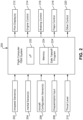
- FIG. 2 illustrates schematic logic following the flight computer 200 to decide whether to reject takeoff.
- the flight computer/fly-by-wire (FBW) controller 200 is in this case comprised of at least one processor 222, a memory 224, and a safe takeoff program 224'. It is configured to automatically and autonomously reject takeoff under certain criteria.
- the flight computer 200 determines takeoff rejection by processing various takeoff parameters including:
- Flight computer 200 conditionally outputs:
- the flight computer 200's output signals command the aircraft automatically execute an RTO by reducing or reversing thrust, applying brakes, increasing drag by controlling flaps down, and decelerate safely to a stop.
- the flight computer 200 is able to determine whether the operational procedures of the aircraft during takeoff are either safe or unsafe.
- the operational procedures during takeoff are defined by the input takeoff parameters.
- a safe takeoff involves agreement between (a) estimated longitudinal acceleration calculated based on presumed weight of the aircraft, and (b) current actual acceleration as measured by an inertial sensor.
- An unsafe set of parameters which leads to a rejection of takeoff, is detected based on an incongruence in the comparison of the estimated longitudinal acceleration and the current measured acceleration.
- the flight computer 200 determines whether an RTO can be safely executed. It is well known that RTO's at high speeds approaching or exceeding V1 can be dangerous. Therefore, the flight computer 200 will only perform an automatic RTO if the measured speed of the aircraft is within a safe range.
- the flight computer 200 executes the rejection of takeoff by displaying on the cockpit that the system has decided to reject takeoff, while reducing the thrust of the aircraft, activating the wheel brakes, and controlling the aerodynamic surfaces (e.g., raising spoilers, lowering flaps, etc.) in order to increase drag to try and bring the aircraft to a safe stop.
- the aerodynamic surfaces e.g., raising spoilers, lowering flaps, etc.
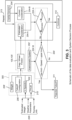
- Figure 3 depicts a non-limiting example data evaluation and system decision process.
- a computer configured to calculate the thrust 210' and V-speeds 302 that should be applied during a takeoff procedure.
- V-speeds or Velocity-speeds are well-known conventional velocity terms used to define critical airspeeds for the operational procedures of aircraft.
- V 1 is the socalled "decision point" - namely the maximum speed during takeoff at which a pilot can safely execute an RTO without overrunning the runway.
- V 2 is defined as the takeoff safety speed.
- V R is the rotation speed, the speed at which the pilot may rotate the aircraft so its nosewheel leaves the ground and it begins to climb into the air.
- the expected longitudinal acceleration value 204-A and the measured acceleration value 204-B are compared in the flight computer 200' of the aircraft as the aircraft begins moving down the runway. This is in the nature of a physics experiment with practical consequences: if the flight computer 200 determines that the two acceleration values are consistent, then normal takeoff procedure 312 is followed and no intervention is required. However, if the flight computer 200' determines that the two acceleration values are not consistent, then there is a problem. Specifically, the estimated weight of the aircraft has been experimentally determined to be incorrect. The pilot is notified of this discrepancy; and the flight computer 200 autonomously performs an RTO if it is safe to do so.
- the safe takeoff program 224'-B is configured to determine whether the aircraft's speed 202' is inside a safe "speed window". Therefore, takeoff rejection 311 is conditioned on whether the measured speed of the aircraft is below a safe stopping speed. If the aircraft is within the safe speed window, then the flight computer 200' automatically aborts the takeoff 311. On the other hand, if the aircraft speed is outside the defined margin of a safe stopping speeds, then the safe takeoff program 224'-B is configured to repeat 313 the comparison of the acceleration values while potentially also warning the pilot that something may be wrong.
- the entire process is transparent to the pilot.
- the pilot does not need to perform any procedure. This will reduce the pilot's workload in a very demanding flight phase, as well as to produce a more consistent operation.
- the new non-limiting technology herein thus proposes a system that automatically rejects or aborts takeoff if erroneous takeoff parameters or data are detected.
- the rejected takeoff shall occur only in a well-defined "speed window" between a Lower limit speed and an upper limit speed, where:
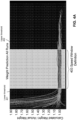
- FIG 4A depicts a graph wherein the concept of a "speed window" is defined.
- the speed window 403 is a margin, bounded by an upper threshold 402 and a lower threshold 401.
- the lower threshold 401 referred to as the Lower Limit Speed (“LLS”), is the specific value where any airspeed below this limit is unmeasurable by the anemometric system due to the fact that the aircraft is not moving fast enough.
- the upper threshold 402 referred to as the Upper Limit Speed (“ULS”)
- ULS Upper Limit Speed
- the graph compares the ratio of calculated and actual weight, acceleration should be the parameter compared, but weight and acceleration are correlated and the final effect is similar.
- Figure 4B considers a non-limiting embodiment of a "speed window", that has a:
- the safety aspect of the safe speed window results from the upper speed limit.
- the lower speed limit is used merely to ensure that the measured aircraft speed is accurate.
- typical anemometric speed sensors do not begin providing valid speed data until the aircraft is moving at above a minimum speed.
- there are other known ways to measure aircraft speed such as GPS, and the particular nature of the low speed threshold (or if any is applied) may depend on the type of speed sensor(s) being used.
- Figure 5 illustrates example non-limiting signal flow of the aircraft's auto rejection system.
- the system is configured to receive dispatch data (e.g., estimated weight 208', weather parameters 208', runway info 208', takeoff configuration 206', etc.) from the ground computer.
- dispatch data e.g., estimated weight 208', weather parameters 208', runway info 208', takeoff configuration 206', etc.
- the parameters calculated by the dispatch computer 300' using the dispatch data are V-speeds (e.g., V 1 , V R , V 2 ), and thrust lever 210 selection.
- V-speeds e.g., V 1 , V R , V 2
- thrust lever 210 selection e.g., thrust lever 210 selection.
- these parameters inputted into the dispatch computer 300 it is also possible to estimate the aircraft's drag 100' and wheel friction forces 105'. With drag 100' and wheel friction forces 105' calculated, it is possible to estimate a longitudinal acceleration value 204-A. This estimated acceleration
- the safe takeoff program 224'-B is configured to determine whether the aircraft's speed 202' is inside a safe "speed window". If the aircraft is within the speed window, then the flight computer 200' automatically aborts the takeoff 311' and autonomously performs an RTO. On the other hand, if the measured speed of the aircraft is outside of the safe speed window, then the safe takeoff program 224'-B is configured to take no action and repeat 313' the comparison of the acceleration values.
- Figure 6A shows a non-limiting means that can be used by the aircraft to calculate the estimated longitudinal acceleration.
- Some inputs used to calculate the estimated longitudinal 610 acceleration come from different sensors or state information that indicate aircraft takeoff configuration 206' (e.g., flap/slat configuration).
- Other input parameters (the ones to be tested) are obtained from dispatch, such parameters including estimated weight 208'.
- Dispatch also supplies additional information such as weather 208' (including air density), runway info 208', etc.). Criteria such as V-speeds 302' and thrust settings 210' are calculated using such inputs (e.g., estimated weight 208' weather 208', runway information 208', etc., as explained above).
- All inputs are processed by a processing unit (e.g., microprocessor) 608 in the aircraft's flight computer 200' and/or by the ground computer or some other computer.
- the processing unit is able to calculate the aircraft's drag and wheel friction forces, making it possible to estimate the longitudinal acceleration of the aircraft 204-A.
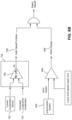
- Figure 6B illustrates an example non-limiting means of determining takeoff rejection by comparing the estimated longitudinal acceleration with the measured acceleration, and determining whether the aircraft is moving at a safe stopping speed.
- Such logic can be implemented in a variety of ways such as by a software controlled process, a gate/logic array, or any other suitable implementation.
- the estimated longitudinal acceleration signal 704 and the measured acceleration signal 702 are received by a subprocessing unit 700 in the flight computer 200'.
- the flight computer is configured to receive both acceleration values and compare them using a comparator 706.
- Comparator 706 determines whether to output a safe takeoff signal 312' (meaning that both accelerations are substantially equal) or send a signal 708 to a structural and/or software based logic to check whether it is safe to reject takeoff.
- the anemometric system 804 measures wind speed to determine whether the aircrafts' speed is within a range defined by a safe speed window.
- the anemometric system 804 measures the speed of the wind relative to the aircraft and thus the speed of the aircraft (once wind speed and direction is taken into account).
- the anemometric system 804 outputs a measurement value to comparator 806, which determines whether the measured wind speed value is between the lower limit and the upper limit defined by the speed window. If the measured value is within the range defined between the limits, then a signal 808 is sent to the structural and/or software based logic AND gate.
- the structural and/or software based logic AND gate is configured to follow the Boolean logic of an AND gate, meaning that both conditions must be true in order for the gate to generate a true output.
- Positive or negative logic e.g., NAND
- NAND negative logic
- Figure 7 illustrates a non-limiting example of how an aircraft's inertial sensors 204' can be used to measure longitudinal acceleration.
- inertial sensors are devices designed to measure inertial values such as acceleration and rotation. Examples of inertial sensors include gyrosensors 500 and accelerometers 501.
- accelerometers 501 such as mechanical accelerometers that consists of devices that measures the displacement of an inertial mass suspended by a spring.
- mechanical accelerometers that consists of devices that measures the displacement of an inertial mass suspended by a spring.
- SAW surface acoustic wave
- MEMS accelerometers that uses capacitance to measure displacement of a minute mass floating on springs.
- gyrosensors such as mechanical, optical, and MEMS.
- Mechanical gyroscopes often used in the aircraft industry to determine aircraft attitude during flight consist of a spinning wheel mounted on two gimbals which allow the wheel to rotate in all three axes.
- Optical gyroscopes e.g., fiber optic gyroscopes "FOG"
- a MEMS gyrosensor usually contains a vibratory elements to measure the Coriolis effect. For example, a single mass which is driven to vibrate along a drive axis. When the gyroscope is rotation a secondary vibration is induced along the perpendicular axis due to the Coriolis force.
- the angular velocity or rate output by such a system indicates the rate of change of attitude. This can be differentiated to determine acceleration.
- Such devices can have any number of axes, including triaxial meaning that they measure all three degrees of freedom. Once such inertial values are sensed, they can be processed using conventional matrix multiplication to determine the component of acceleration in any desired particular direction.
- Inertial sensors 500, 501 are thus able to measure inertial values such as the angular velocities ( ⁇ x 500-A, ⁇ y 500-B, ⁇ z 500-C) via the gyroscopes 500, and the accelerations (a x 501-A, a y 501-B, a z 501-C) via the accelerometers 501.
- Appropriate conventional axes transformations (which also involve knowing the orientation of the measured axes to the physical longitudinal centerline of the aircraft) can be used to calculate current longitudinal acceleration of the aircraft.
Landscapes
- Engineering & Computer Science (AREA)
- Aviation & Aerospace Engineering (AREA)
- Radar, Positioning & Navigation (AREA)
- Remote Sensing (AREA)
- Physics & Mathematics (AREA)
- General Physics & Mathematics (AREA)
- Automation & Control Theory (AREA)
- Traffic Control Systems (AREA)
Description
- The technology herein relates to aircraft performance and automation, and more particularly to systems and methods for ensuring safe takeoff in the event incorrect takeoff information is inputted to a flight computer. In still more detail, the technology herein causes the aircraft to automatically and autonomously reject a takeoff if actual measured acceleration deviates from calculations based on pre-flight parameters and the speed of the aircraft traveling down the runway is within a safe speed range to guarantee a successful low inertia rejected takeoff.
-
US 9 164 505 B1 -
US 2011/118909 A1 discloses a system for predicting where an aircraft will be during takeoff when reaching V1, and if an incorrect weight has been used to compute V speeds (and consequently other parameters for the takeoff operation) and if V1 cannot be reached given the length of the runway, the system outputs an alert to the flight crew. -
EP 3 251 947 A1 is a document pursuant to Art. 54(3) EPC.WO2013091057 discloses a safe takeoff monitoring system which checks the actual physical parameters of an airplane during takeoff, determines the actual takeoff weight, and warns the pilot to interrupt the takeoff if any dangerous situation is developing, before a high energy abort is necessary. - Commercial airlines perform tens of millions of takeoffs annually. Only a very small percentage of attempted takeoffs result in rejected takeoffs (RTO's). Pilots decide to execute RTO's due to a variety of factors including engine failure, wheel/tire failure, incorrect pre-flight configuration, indicator/warning lights, lack of crew coordination, and bird strikes. An RTO at a low speed rarely results in any adverse consequences. High-speed RTO's, on the other hand, can potentially cause the airplane to overrun the end of the runway, with catastrophic consequences. See Federal Aviation Administration, "Pilot Guide to Takeoff Safety", retrieved from https://www.faa.gov/other_visit/aviation_industry/airline_operators/training/media /takeoff_safety.pdf
- A recurring issue in aviation is errors in aircraft dispatch and/or the incorrect pilot inputs of takeoff parameters. Before takeoff, the flight control computer is typically initialized with certain parameters pertinent to the takeoff. These inputs include weight, configuration (flap position), thrust and takeoff speeds (V1, VR and V2). Since thrust and V speeds are critical to proper takeoff, errors in inputting these parameters can lead to serious aircraft accidents. The table below presented some accidents related to wrong takeoff data:
Fatalities Date Type Registration Operator Location 271 25-May-79 DC-10-10 N110AA A Airlines USA 248 27-Mar-77 Boeing 747 PH-BUF KLM Spain 154 16-Aug-87 DC-9-82 N312RC Northwest A USA 154 20-Aug-08 DC-9-82 EC-HFP Spanair Spain 141 25-Dec-03 Boeing 727 3X-GDO UTA Benin 130 3-Jun-62 Boeing 707 F-BHSM Air France France 110 8-Oct-01 DC-9-87 SE-DMA SAS Italy 83 31-Oct-00 Boeing 747 9V-SPK Singapore Ai Taiwan 82 28-Aug-93 Yakov 40 87995 Tajikistan Ai Tajikistan - Such types of accidents are often consequences of a lower aircraft capability to accelerate and/or climb. A particularly terrible example where an accident was related to wrong takeoff configuration (and overweight) is the case of Union des Transports Africains de Guinee (UTA) Flight 141 which departed Conakry, Guinea for a scheduled flight to Beirut, Lebanon on Christmas Day, December 25, 2003. The Boeing 727 departed at 10:07 carrying 86 passengers and a crew of 10. It arrived at Cotonou at 12:25 where nine passengers disembarked. A total of 63 people had checked in at the Cotonou airport check-in-desk. Ten others boarded from a flight that had arrived from another airport. Passenger boarding and baggage loading took place in a climate of great confusion. The plane was full and it is thought that there were more passengers aboard the plane than had officially checked in.
- The flight crew began pre-flight checklist at 13:47 and were cleared to roll at 13:52. Passengers were still standing in the aisles at that time. At 13:58:01, the thrust lever was advanced, 14 seconds later the brakes were released and the Boeing 727 began accelerating down the runway. 46 seconds after the brakes were released, the captained announced V1 and VR speeds. At that moment the aircraft was 1620 meters down the runway at a speed of 70.50 m/s (137 knots).
- The co-pilot pulled back on the control column to rotate the plane at VR. This action initially had no effect on the airplane's angle of attack. The Captain called "Rotate, rotate", and the co-pilot pulled back harder. The angle of attack only increased slowly. The pilot did not command an RTO. Seven seconds later, at a speed of 76.14 m/s (148 knots) and 2 100 meters down the runway, the nose just slowly rose. The 727 barely climbed away from the ground, causing its main undercarriage to strike localizer antennas at the end of the runway and strike a 3- meter-high small building housing radio equipment. The plane continued beyond the end of the runway, smashing through a concrete airport boundary fence and slamming into the beach. The fuselage broke into several pieces. At least 144 people died in the crash.
- The official explanation of the crash was that the aircraft's weight exceeded its maximum weight capacity. The accident resulted from difficulty that the flight crew encountered in performing rotation with an overloaded airplane whose forward center of gravity was unknown to them.
- To avoid such disasters, the preflight operational engineer typically carefully calculates the takeoff weight (TOW) of the aircraft based on a weight & balance spreadsheet. The spreadsheet and/or calculation presents some statistical simplifications which decrease the level of accuracy. An example is the passenger estimated weight that can significantly differ from the real one. The same can be related to the baggage and other cargo.
- The takeoff "Vspeeds" (V1, VR, V2) evaluation is based on the takeoff weight. Therefore, if the weight is wrong, so are the takeoff speeds. It is also possible to incorrectly calculate the V-speeds even if the weight determination is right. Even if the operational engineer's calculations are all correct, the pilot and/or dispatch inputs into the flight computer can be wrong.
- Today, the only way to confirm if the data is right is to recalculate and/or re-check the input data. This is of course not a failure-proof processes.
- Some in the past have proposed ways to monitor if the data are correct and, in case of a detected error, alert the pilot to make some action. But since the pilot workload is higher at takeoff, such proposals must somehow assure that there is enough runway remaining to stop the aircraft without a runway excursion (overrun) in case the pilot decides to abort the takeoff.
- Although such prior techniques propose a way to check if there are some errors on dispatch, they all introduce a higher pilot workload, since the pilot must understand the situation and must decide to make the first action to abort the takeoff. The invention provides a system according to
claim 1 and a method according to claim 6, with embodiments defined in the dependent claims. - The invention provides a system for an aircraft and a method of automatically rejecting take off as laid out in
independent claims 1 and 8. Embodiments of the invention are defined in the dependent claims. - The following detailed description of examples of this invention is to be read in conjunction with the drawings, of which:
-
Figure 1 is an example showing forces (e.g., thrust, wheel friction, wheel drag, configuration drag, etc.) and a resulting longitudinal acceleration that an aircraft incurs during takeoff. -
Figure 2 is an example schematic block diagram of an example non-limiting safe takeoff system for conditionally automatically rejecting takeoff. -
Figure 3 schematically shows an example non-limiting data evaluation and system decision process. -
Figure 4A illustrates an example non-limiting definition of a safe speed window based on ratios of actual vs. predicted aircraft weight, the window providing an upper threshold and a lower threshold. -
Figure 4B illustrates a non-limiting example of a safe speed window with preferable upper and lower speed ranges. -
Figure 5 illustrates signal flow of an example non-limiting embodiment of an automatic takeoff rejection system. -
Figure 6A illustrates how estimated longitudinal acceleration can be calculated. -
Figure 6B shows example non-limiting automatic takeoff rejection decision logic. -
Figure 7 illustrates how current acceleration may be measured/determined. -
Figure 1 showsforces including drag 100 andwheel friction 105 that an aircraft typically experiences during the takeoff phase of flight. The Figure shows an aircraft moving down a runway at a longitudinal acceleration that is determined in accordance with F=ma, where F are the forces being exerted on the aircraft, m is the mass of the aircraft, and a is the acceleration. - The mass a is determined based on the total weight of the aircraft, including the aircraft itself, fuel, passengers, baggage and cargo.
- The force F on the aircraft has several components. One component is the amount of thrust produced by the engines. Another component is the friction and drag exerted on the aircraft. Drag is defined as the resistance that opposes the
direction 103 that an aircraft is moving. - Graphic 105' is a free-body-diagram used to show that the force related to forward acceleration (Fa) is greater than all other forces involved in the aircraft's takeoff phase. Such other forces include the force of gravity (Fg) that is pulling the aircraft towards the ground, the force of friction (Fµ) (opposite to the direction of aircraft movement) and the normal force (Fn), which are responsible for the drag that the aircraft incurs during takeoff.
- There are many factors that affect the magnitude of the
drag force 100 including the aerodynamic shape of the aircraft (including its current configuration, such as the position of the flaps), the viscosity of the air (which depends on air temperature and altitude), and the velocity of the aircraft. All of the individual components of drag are combined into a single aircraft drag magnitude. -
Rolling friction 105 is the resistive force that slows down the motion of a rolling wheel. It is also called rolling resistance. - Once a wheel is rolling, the resistance to the motion is typically a combination of several friction forces at the point of contact between the wheel and the ground or other surface. This assumes the brakes are off - since the brakes are designed to increase rolling friction. The amount of rolling friction depends on several factors including the weight of the aircraft (since the weight exerts a downward force on the wheels that increase the friction coefficient), the inflation and type of tires, and the composition of the runway surface.
- One of the insights provided by the present non-limiting technology: the longitudinal acceleration can be directly measured using an inertial sensor, and used as a check against the weight and associated parameters calculated by the flight engineer/dispatch.
-
Figure 2 illustrates schematic logic following theflight computer 200 to decide whether to reject takeoff. The flight computer/fly-by-wire (FBW)controller 200 is in this case comprised of at least oneprocessor 222, amemory 224, and a safe takeoff program 224'. It is configured to automatically and autonomously reject takeoff under certain criteria. Theflight computer 200 determines takeoff rejection by processing various takeoff parameters including: - signals from the airspeed sensor(s) 202,
- signals from inertial sensor(s) 204,
- signals from aircraft configuration sensor(s) 206,
- dispatch/
pilot input 208, and -
thrust lever 210 selection. -
Flight computer 200 conditionally outputs: - a signal to the pilots' display 212 (e.g., PDF, EICAS),
- a signal to the
engine control 214, - a signal to the
braking control 216, - a signal to the flaps control 218, and
- signals to other control(s) 220.
- In appropriate cases, the
flight computer 200's output signals command the aircraft automatically execute an RTO by reducing or reversing thrust, applying brakes, increasing drag by controlling flaps down, and decelerate safely to a stop. - In determining whether to execute an RTO, the
flight computer 200 is able to determine whether the operational procedures of the aircraft during takeoff are either safe or unsafe. The operational procedures during takeoff are defined by the input takeoff parameters. A safe takeoff involves agreement between (a) estimated longitudinal acceleration calculated based on presumed weight of the aircraft, and (b) current actual acceleration as measured by an inertial sensor. An unsafe set of parameters, which leads to a rejection of takeoff, is detected based on an incongruence in the comparison of the estimated longitudinal acceleration and the current measured acceleration. - However, not all such incongruences are the basis for an automatic RTO. In particular, the
flight computer 200 also determines whether an RTO can be safely executed. It is well known that RTO's at high speeds approaching or exceeding V1 can be dangerous. Therefore, theflight computer 200 will only perform an automatic RTO if the measured speed of the aircraft is within a safe range. - If an incongruence is detected, the
flight computer 200 executes the rejection of takeoff by displaying on the cockpit that the system has decided to reject takeoff, while reducing the thrust of the aircraft, activating the wheel brakes, and controlling the aerodynamic surfaces (e.g., raising spoilers, lowering flaps, etc.) in order to increase drag to try and bring the aircraft to a safe stop. -
Figure 3 depicts a non-limiting example data evaluation and system decision process. In response to estimated weight 208' provided by the flight engineer/dispatch system, weather parameters 208' (e.g ., temperature, wind, etc.) and airport data 208' (runway information), a computer (either theflight computer 200 on board the aircraft, a ground computer at dispatch, or some other computer) is configured to calculate the thrust 210' and V-speeds 302 that should be applied during a takeoff procedure. V-speeds or Velocity-speeds are well-known conventional velocity terms used to define critical airspeeds for the operational procedures of aircraft. - V1 is the socalled "decision point" - namely the maximum speed during takeoff at which a pilot can safely execute an RTO without overrunning the runway. V2 is defined as the takeoff safety speed. And VR is the rotation speed, the speed at which the pilot may rotate the aircraft so its nosewheel leaves the ground and it begins to climb into the air.
- Based on these same parameters inputted into the
dispatch computer 300, (weight 208', takeoff configuration 206', V-speeds 302, and thrust 210') it is also possible to estimate the aircraft'sdrag 100 and wheel friction forces 105. By estimating thrust 210', drag 100', and wheel friction forces 105' it is possible to estimate a longitudinal acceleration value 204-A of the aircraft based on the dispatch information. This estimated acceleration value is checked to measured acceleration 204-B that is obtained from the inertial sensor(s) 204' of the aircraft as the aircraft accelerates down the runway. - In simple terms, if the measured acceleration differs significantly from the estimated acceleration, then the actual weight of the aircraft is likely not the same as the estimated weight used to calculate the estimates acceleration. F=ma can be rewritten as a = F/m. So for the equation:

- In the example shown, the expected longitudinal acceleration value 204-A and the measured acceleration value 204-B are compared in the flight computer 200' of the aircraft as the aircraft begins moving down the runway. This is in the nature of a physics experiment with practical consequences: if the
flight computer 200 determines that the two acceleration values are consistent, thennormal takeoff procedure 312 is followed and no intervention is required. However, if the flight computer 200' determines that the two acceleration values are not consistent, then there is a problem. Specifically, the estimated weight of the aircraft has been experimentally determined to be incorrect. The pilot is notified of this discrepancy; and theflight computer 200 autonomously performs an RTO if it is safe to do so. - To determine safety of an RTO, the safe takeoff program 224'-B is configured to determine whether the aircraft's speed 202' is inside a safe "speed window". Therefore,
takeoff rejection 311 is conditioned on whether the measured speed of the aircraft is below a safe stopping speed. If the aircraft is within the safe speed window, then the flight computer 200' automatically aborts thetakeoff 311. On the other hand, if the aircraft speed is outside the defined margin of a safe stopping speeds, then the safe takeoff program 224'-B is configured to repeat 313 the comparison of the acceleration values while potentially also warning the pilot that something may be wrong. - In one example non-limiting embodiment, the entire process is transparent to the pilot. The pilot does not need to perform any procedure. This will reduce the pilot's workload in a very demanding flight phase, as well as to produce a more consistent operation.
- The new non-limiting technology herein thus proposes a system that automatically rejects or aborts takeoff if erroneous takeoff parameters or data are detected. In order to prevent a runway excursion or overrun, the rejected takeoff shall occur only in a well-defined "speed window" between a Lower limit speed and an upper limit speed, where:
- Lower Limit Speed: Below this value, the anemometric system is not capable of estimating the speed of the aircraft with a necessary accuracy.
- Upper Limit Speed: Up to this speed, it is possible to guarantee that the aircraft can safely abort the takeoff without the risk of a runway excursion or overrun. In layman's terms, this means a low kinetic energy rejected takeoff.
-
Figure 4A depicts a graph wherein the concept of a "speed window" is defined. Thespeed window 403 is a margin, bounded by anupper threshold 402 and alower threshold 401. Thelower threshold 401, referred to as the Lower Limit Speed ("LLS"), is the specific value where any airspeed below this limit is unmeasurable by the anemometric system due to the fact that the aircraft is not moving fast enough. In the same manner, theupper threshold 402, referred to as the Upper Limit Speed ("ULS"), is the limit that guarantees a safe rejection of takeoff without the risk of a runway excursion. Although the graph compares the ratio of calculated and actual weight, acceleration should be the parameter compared, but weight and acceleration are correlated and the final effect is similar. -
Figure 4B considers a non-limiting embodiment of a "speed window", that has a: - Lower Limit: Typically, this value should be around 15 to 25 m/ (30 to 50 knots), preferably around 15 to 20 m/s (30 - 40 knots).
- Upper Limit: This speed should be in the order of 35 to 50 m/s (70 to 100 knots), preferably around 40 to 50 m/s (80 - 100 knots).
- In the non-limiting example, with the speed window considered, it is not necessary to estimate the remaining distance on the runway, since with low energy the aircraft will be capable to abort the takeoff in any runway that it can be dispatched to.
- It should be noted that the safety aspect of the safe speed window results from the upper speed limit. In the example embodiment, the lower speed limit is used merely to ensure that the measured aircraft speed is accurate. As is well known, typical anemometric speed sensors do not begin providing valid speed data until the aircraft is moving at above a minimum speed. However, there are other known ways to measure aircraft speed such as GPS, and the particular nature of the low speed threshold (or if any is applied) may depend on the type of speed sensor(s) being used.
- However, it can be seen from
Figures 4A and4B that for a wide range of estimated to actual weight values, the resulting speed data statistically converge at above a low speed threshold. This is because for a given thrust, the rate of change of velocity depends on weight. This means that above a low speed threshold, the same procedure can be applied to a wide variety of weight discrepancies to result in a valid test. -
Figure 5 illustrates example non-limiting signal flow of the aircraft's auto rejection system. The system is configured to receive dispatch data (e.g., estimated weight 208', weather parameters 208', runway info 208', takeoff configuration 206', etc.) from the ground computer. Among the parameters calculated by the dispatch computer 300' using the dispatch data are V-speeds (e.g., V1, VR, V2), and thrustlever 210 selection. As explained before, with these parameters inputted into thedispatch computer 300 it is also possible to estimate the aircraft's drag 100' and wheel friction forces 105'. With drag 100' and wheel friction forces 105' calculated, it is possible to estimate a longitudinal acceleration value 204-A. This estimated acceleration value is compared 224'-A to measured acceleration 204' that is obtained from the inertial sensor(s) 204'. - If the measured and estimated acceleration values match within a certain tolerance, then normal takeoff procedure 312' is followed from the safe takeoff program 224'-A. However, if the flight computer 200' determines that the acceleration values are very different, then the safe takeoff program 224'-B is configured to determine whether the aircraft's speed 202' is inside a safe "speed window". If the aircraft is within the speed window, then the flight computer 200' automatically aborts the takeoff 311' and autonomously performs an RTO. On the other hand, if the measured speed of the aircraft is outside of the safe speed window, then the safe takeoff program 224'-B is configured to take no action and repeat 313' the comparison of the acceleration values.
-
Figure 6A shows a non-limiting means that can be used by the aircraft to calculate the estimated longitudinal acceleration. Some inputs used to calculate the estimated longitudinal 610 acceleration come from different sensors or state information that indicate aircraft takeoff configuration 206' (e.g., flap/slat configuration). Other input parameters (the ones to be tested) are obtained from dispatch, such parameters including estimated weight 208'. Dispatch also supplies additional information such as weather 208' (including air density), runway info 208', etc.). Criteria such as V-speeds 302' and thrust settings 210' are calculated using such inputs (e.g., estimated weight 208' weather 208', runway information 208', etc., as explained above). All inputs are processed by a processing unit (e.g., microprocessor) 608 in the aircraft's flight computer 200' and/or by the ground computer or some other computer. The processing unit is able to calculate the aircraft's drag and wheel friction forces, making it possible to estimate the longitudinal acceleration of the aircraft 204-A. -
Figure 6B illustrates an example non-limiting means of determining takeoff rejection by comparing the estimated longitudinal acceleration with the measured acceleration, and determining whether the aircraft is moving at a safe stopping speed. Such logic can be implemented in a variety of ways such as by a software controlled process, a gate/logic array, or any other suitable implementation. The estimatedlongitudinal acceleration signal 704 and the measuredacceleration signal 702 are received by asubprocessing unit 700 in the flight computer 200'. The flight computer is configured to receive both acceleration values and compare them using acomparator 706.Comparator 706 determines whether to output a safe takeoff signal 312' (meaning that both accelerations are substantially equal) or send asignal 708 to a structural and/or software based logic to check whether it is safe to reject takeoff. - Concurrently, the
anemometric system 804 measures wind speed to determine whether the aircrafts' speed is within a range defined by a safe speed window. Theanemometric system 804 measures the speed of the wind relative to the aircraft and thus the speed of the aircraft (once wind speed and direction is taken into account). Theanemometric system 804 outputs a measurement value tocomparator 806, which determines whether the measured wind speed value is between the lower limit and the upper limit defined by the speed window. If the measured value is within the range defined between the limits, then asignal 808 is sent to the structural and/or software based logic AND gate. - The structural and/or software based logic AND gate is configured to follow the Boolean logic of an AND gate, meaning that both conditions must be true in order for the gate to generate a true output. Positive or negative logic (e.g., NAND) can be used in a well-known manner. For the system to execute the automatic takeoff rejection, both discrepancy in acceleration values and airspeed within designated speed window, must be true.
-
Figure 7 illustrates a non-limiting example of how an aircraft's inertial sensors 204' can be used to measure longitudinal acceleration. Generally speaking, inertial sensors are devices designed to measure inertial values such as acceleration and rotation. Examples of inertial sensors includegyrosensors 500 andaccelerometers 501. - There are many types of
accelerometers 501, such as mechanical accelerometers that consists of devices that measures the displacement of an inertial mass suspended by a spring. Another type of accelerometer is the surface acoustic wave (SAW) accelerometer which consists of a cantilever beam which resonates at a particular frequency, when acceleration is applied the beam bends changing the frequency, the change in frequency can be used to determine the acceleration. Yet another type of accelerometer is the MEMS accelerometers that uses capacitance to measure displacement of a minute mass floating on springs. - There are many different varieties of gyrosensors, such as mechanical, optical, and MEMS. Mechanical gyroscopes often used in the aircraft industry to determine aircraft attitude during flight consist of a spinning wheel mounted on two gimbals which allow the wheel to rotate in all three axes. Optical gyroscopes (e.g., fiber optic gyroscopes "FOG") use the interference of light to measure angular velocity. A MEMS gyrosensor usually contains a vibratory elements to measure the Coriolis effect. For example, a single mass which is driven to vibrate along a drive axis. When the gyroscope is rotation a secondary vibration is induced along the perpendicular axis due to the Coriolis force. The angular velocity or rate output by such a system indicates the rate of change of attitude. This can be differentiated to determine acceleration.
- Such devices can have any number of axes, including triaxial meaning that they measure all three degrees of freedom. Once such inertial values are sensed, they can be processed using conventional matrix multiplication to determine the component of acceleration in any desired particular direction.
-
Inertial sensors gyroscopes 500, and the accelerations (ax 501-A, ay 501-B, az 501-C) via theaccelerometers 501. Appropriate conventional axes transformations (which also involve knowing the orientation of the measured axes to the physical longitudinal centerline of the aircraft) can be used to calculate current longitudinal acceleration of the aircraft.
Claims (10)
- A system for an aircraft, the system comprising:at least one inertial sensor (204') producing a first signal;at least one wind speed sensor (202) producing a second signal; andat least one flight computer (200), operatively coupled to the at least one inertial sensor (204') and the at least one wind speed sensor (202), the at least one flight computer (200) configured to:measure an acceleration (204-B) in response to the first signal;calculate an expected estimated acceleration value (204-A) in response to an estimated aircraft weight (208'), runway information (208'), weather parameters (208'), and takeoff configuration (206');compare the measured acceleration (204-B) with the expected estimated acceleration value (204-A);determine whether the measured acceleration differs significantly from the expected estimated acceleration value;in response to the second signal, determine whether the aircraft is operating below an upper limit speed guaranteeing that the aircraft can safely perform a low kinetic energy rejected takeoff without the risk of a runway excursion or overrun;if the measured acceleration is determined to differ significantly from the expected estimated acceleration value and the aircraft is determined to be operating below the upper limit speed, automatically issue control signals to automatically abort takeoff conditioned on both the comparison and the speed determination, the control signals controlling the aircraft to automatically execute a rejected takeoff by reducing or reversing thrust, applying brakes and increasing drag by controlling aerodynamic control surfaces to bring the aircraft to a safe stop.
- The system of claim 1, wherein the inertial sensor (204') comprises an accelerometer (501).
- The system of claim 1 or 2, wherein the inertial sensor (204') comprises a gyrosensor (500); and/or wherein the wind speed sensor (202) comprises an anemometer.
- The system of any of the preceding claims, further including a sensor (206) configured to measure parameters indicative of aircraft configuration.
- The system of any of the preceding claims, wherein the at least one flight computer (200) further comprises:
at least one processor (222) and a memory (224). - The system of any of the preceding claims, wherein the at least one flight computer (200) is configured to:
in response to the second signal, determine whether the aircraft is operating in a safe speed window (403) between a lower limit speed and the upper limit speed, wherein the lower limit speed is the speed below which the wind speed sensor (202) is non capable of providing valid speed data,
wherein said control signals to automatically abort takeoff are automatically issued if the measured acceleration is determined to differ significantly from the expected estimated acceleration value and the aircraft is determined to be operating within the safe speed window (403). - The system of any of the preceding claims, wherein the lower limit speed is around 15 to 25 m/s (30 to 50 knots), preferably around 15 to 20 m/s (30 to 40 knots), and the upper limit speed is around 35 to 50 m/s (70 to 100 knots), preferably around 40 to 50 m/s (80 to 100 knots).
- A method of automatically rejecting takeoff comprising:a) measuring acceleration (204-B) in response to an inertial sensing signal;b) comparing the measured acceleration (204-B) with an expected estimated acceleration value (204-A) calculated in response to an estimated aircraft weight (208'), runway information (208'), weather parameters (208'), and takeoff configuration (206');c) determining, in response to a speed signal, whether the aircraft is operating within a safe speed window (403) guaranteeing the aircraft can safely perform a low kinetic energy rejected takeoff without the risk of a runway excursion or overrun;d) conditioned on both the acceleration comparison and the safe speed window determination, issuing control signals to automatically abort takeoff, the control signals controlling the aircraft to reduce or reverse thrust, apply brakes, and increase drag by controlling aerodynamic control surfaces to bring the aircraft to a safe stop.
- The method of claim 8, further including in said safe speed window an upper (402) limit of favorable aircraft speed.
- The method of claim 8 or 9, further including producing the signal using wind speed sensor(s).
Applications Claiming Priority (1)
| Application Number | Priority Date | Filing Date | Title |
|---|---|---|---|
| US15/698,337 US10429856B2 (en) | 2017-09-07 | 2017-09-07 | Safe takeoff system |
Publications (2)
| Publication Number | Publication Date |
|---|---|
| EP3453623A1 EP3453623A1 (en) | 2019-03-13 |
| EP3453623B1 true EP3453623B1 (en) | 2024-12-18 |
Family
ID=63528607
Family Applications (1)
| Application Number | Title | Priority Date | Filing Date |
|---|---|---|---|
| EP18193194.0A Active EP3453623B1 (en) | 2017-09-07 | 2018-09-07 | Safe takeoff system |
Country Status (3)
| Country | Link |
|---|---|
| US (1) | US10429856B2 (en) |
| EP (1) | EP3453623B1 (en) |
| CN (1) | CN109466783B (en) |
Families Citing this family (13)
| Publication number | Priority date | Publication date | Assignee | Title |
|---|---|---|---|---|
| US20190354644A1 (en) * | 2018-05-18 | 2019-11-21 | Honeywell International Inc. | Apparatuses and methods for detecting anomalous aircraft behavior using machine learning applications |
| GB2580374A (en) * | 2019-01-07 | 2020-07-22 | Ge Aviat Systems Ltd | Aircraft airspeed system and method of cross checking airspeed |
| US11414175B2 (en) | 2019-04-01 | 2022-08-16 | Pratt & Whitney Canada Corp. | Method and system for operating an aircraft powerplant |
| US11254442B2 (en) * | 2019-04-29 | 2022-02-22 | The Boeing Company | Logic control for autonomously and manually locking overhead bins for enhanced safety |
| CN110186468B (en) * | 2019-05-27 | 2021-11-12 | 北京主线科技有限公司 | High-precision map making method and device for automatic driving |
| US11837099B2 (en) * | 2019-11-22 | 2023-12-05 | Ge Aviation Systems Limited | Aircraft flight management system |
| US20220024601A1 (en) * | 2020-07-23 | 2022-01-27 | Gulfstream Aerospace Corporation | Controllers and aircraft with variable engine thrust takeoff system |
| US11580864B2 (en) * | 2020-08-20 | 2023-02-14 | Gulfstream Aerospace Corporation | Take-off performance prediction and alerting system |
| US12025994B2 (en) * | 2020-12-23 | 2024-07-02 | Rockwell Collins, Inc. | Rejected takeoff aircraft system and method |
| US11685546B2 (en) * | 2021-09-13 | 2023-06-27 | The Boeing Company | High-speed rejected takeoff detection |
| US20230166857A1 (en) * | 2021-11-29 | 2023-06-01 | Raytheon Technologies Corporation | Final takeoff speed determination for an aircraft |
| FR3145217B1 (en) * | 2023-01-25 | 2026-04-10 | Airbus Operations Sas | SYSTEM FOR GENERATING AN ANOMALY SIGNAL DURING TAKEOFF ON BOARD AN AIRCRAFT |
| CN119649651B (en) * | 2024-12-17 | 2026-03-24 | 中国航空工业集团公司西安飞机设计研究所 | A method and system for determining whether a transport aircraft can take off due to overweight conditions while considering risk time. |
Family Cites Families (38)
| Publication number | Priority date | Publication date | Assignee | Title |
|---|---|---|---|---|
| US3066896A (en) | 1959-04-27 | 1962-12-04 | Air Logistics Corp | Method and means for decelerating aircraft on runways |
| US4490802A (en) | 1981-12-21 | 1984-12-25 | Sperry Corporation | Takeoff weight computer apparatus for aircraft |
| US4837695A (en) | 1986-03-12 | 1989-06-06 | E-Systems, Inc. | Method and apparatus for predicting and monitoring aircraft takeoff performance |
| US4843554A (en) | 1987-08-06 | 1989-06-27 | The United States Of America As Represented By The United States National Aeronautics And Space Administration | Airplane takeoff and landing performance monitoring system |
| US5353022A (en) | 1987-08-06 | 1994-10-04 | The United States Of America As Represented By The Administrator Of The National Aeronautics And Space Administration | Airplane takeoff and landing performance monitoring system |
| US5142478A (en) | 1988-09-23 | 1992-08-25 | Crook Mitchell M | Computerized aircraft landing and takeoff system |
| FR2650101B1 (en) | 1989-06-20 | 1991-12-20 | Aerospatiale | SYSTEM FOR PROVIDING ON-AIRCRAFT AN INFORMATION SIGNAL DURING TAKE-OFF WITH ALERT OR ALARM IN CASE OF ANOMALY |
| FR2725063B1 (en) | 1994-09-28 | 1997-01-10 | Aerospatiale | SYSTEM FOR THE PREPARATION ON BOARD OF AN AIRCRAFT OF AN INFORMATION SIGNAL, ALERT OR ALARM IN CASE OF ANOMALY DURING TAKEOFF |
| JP2002230700A (en) | 2001-02-02 | 2002-08-16 | Hiroshi Ito | Event take-off and landing automatic detection system |
| US6614397B2 (en) | 2001-11-14 | 2003-09-02 | The Boeing Company | Wrong runway alert system and method |
| US6527225B1 (en) | 2002-04-30 | 2003-03-04 | Sikorsky Aircraft Corporation | Method for performing an automated category a takeoff |
| FR2894045B1 (en) | 2005-11-28 | 2008-02-15 | Airbus France Sas | METHOD FOR CONTROLLING TAKE-OFF OR LANDING PARAMETERS AND ASSOCIATED DEVICE |
| FR2894046B1 (en) | 2005-11-28 | 2008-02-15 | Airbus France Sas | METHOD FOR DETECTING AN INPUT ERROR OF ONE OF THE TAKE-OFF PARAMETERS IN A FLIGHT MANAGEMENT SYSTEM |
| US20080215198A1 (en) | 2006-09-22 | 2008-09-04 | Richards Robert E | Method and apparatus for providing takeoff runway information and predicting end of runway overrun |
| US7720579B2 (en) | 2006-12-20 | 2010-05-18 | The Boeing Company | Method, system, and computer program product for performance monitored aircraft rejected takeoff braking |
| US8123163B2 (en) | 2007-04-20 | 2012-02-28 | The Boeing Company | Aircraft kinetic landing energy conversion system |
| FR2935521B1 (en) | 2008-08-26 | 2010-09-17 | Airbus France | METHOD FOR VERIFYING THE COHERENCE OF THE AIRCRAFT DEPARTURE PARAMETERS WITH A AVAILABLE TRACK LENGTH |
| NL2002064C (en) | 2008-10-07 | 2010-04-08 | Robertus Gerardus De Boer | DIFFERENTIATED STOW POWER STARTING METHOD FOR AN AIRCRAFT. |
| FR2943423B1 (en) | 2009-03-17 | 2011-06-24 | Airbus France | METHOD AND DEVICE FOR ESTIMATING AT AT LEAST ONE WIND CHARACTERISTIC ON AN AIRCRAFT |
| US20110040431A1 (en) * | 2009-08-11 | 2011-02-17 | Honeywell International Inc. | Automated take off control system and method |
| US20110118909A1 (en) | 2009-11-19 | 2011-05-19 | Honeywell International Inc. | Systems and methods of detecting low takeoff performance due to incorrect weight information |
| US9056669B2 (en) * | 2011-09-30 | 2015-06-16 | Aurora Flight Sciences Corporation | Hardware-based weight and range limitation system, apparatus and method |
| US10315777B2 (en) * | 2011-12-22 | 2019-06-11 | Embraer S.A. | Safe takeoff monitoring system |
| WO2013114388A1 (en) | 2011-12-23 | 2013-08-08 | Muthukumar Prasad | Smart active tyre pressure optimising system |
| FR2988868B1 (en) * | 2012-03-30 | 2015-04-24 | Parrot | METHOD FOR CONTROLLING A MULTI-ROTOR ROTOR SAILING DRONE WITH ESTIMATION AND SIDE WIND COMPENSATION |
| US9164505B1 (en) | 2012-05-22 | 2015-10-20 | The Boeing Company | Automatic rejected takeoff system |
| US8560149B1 (en) | 2012-09-20 | 2013-10-15 | Honeywell International Inc. | Systems and methods for takeoff assistance and analysis |
| US9058742B2 (en) * | 2013-02-12 | 2015-06-16 | Ge Aviation Systems, Llc | Methods for illustrating aircraft situational information |
| JP6097596B2 (en) | 2013-02-28 | 2017-03-15 | 三菱航空機株式会社 | Grand spoiler drive system and aircraft |
| US9296488B2 (en) * | 2013-03-06 | 2016-03-29 | 3Rd Millennium Solutions, Inc. | Aircraft braking early warning system |
| US9296475B2 (en) | 2013-09-24 | 2016-03-29 | The Boeing Company | System and method for reducing the stopping distance of an aircraft |
| US9082301B2 (en) | 2013-10-28 | 2015-07-14 | The Boeing Company | Aircraft stopping performance display and warning |
| CN105247593B (en) * | 2014-04-17 | 2017-04-19 | 深圳市大疆创新科技有限公司 | Flight Controls in Restricted Areas |
| CN105045272B (en) * | 2015-08-07 | 2018-03-20 | 北京航空航天大学 | A kind of automatic takeoff control strategy design of small-sized depopulated helicopter |
| US10202204B1 (en) * | 2016-03-25 | 2019-02-12 | AAR Aerospace Consulting, LLC | Aircraft-runway total energy measurement, monitoring, managing, safety, and control system and method |
| US9738378B1 (en) | 2016-04-08 | 2017-08-22 | The Boeing Company | Display-based flight deck autobrake selection |
| US10815000B2 (en) * | 2016-05-31 | 2020-10-27 | Embraer S.A. | Short rejected takeoff system and method |
| US10831198B2 (en) * | 2017-08-18 | 2020-11-10 | The Boeing Company | Process and machine for making a runway extension speed for an aircraft |
-
2017
- 2017-09-07 US US15/698,337 patent/US10429856B2/en active Active
-
2018
- 2018-09-07 EP EP18193194.0A patent/EP3453623B1/en active Active
- 2018-09-07 CN CN201811042599.XA patent/CN109466783B/en active Active
Also Published As
| Publication number | Publication date |
|---|---|
| US10429856B2 (en) | 2019-10-01 |
| US20190072982A1 (en) | 2019-03-07 |
| EP3453623A1 (en) | 2019-03-13 |
| CN109466783A (en) | 2019-03-15 |
| BR102018068115A2 (en) | 2019-05-28 |
| CN109466783B (en) | 2023-11-03 |
Similar Documents
| Publication | Publication Date | Title |
|---|---|---|
| US10429856B2 (en) | Safe takeoff system | |
| US11960303B2 (en) | Situational awareness, vehicle control, and/or contingency planning for aircraft actuator failure | |
| CN104471502B (en) | Safe Takeoff Monitoring System | |
| CN102915652B (en) | aircraft traffic separation system and method | |
| US8744738B2 (en) | Aircraft traffic separation system | |
| EP2908303B1 (en) | System for providing landing exceedance warnings and avoidance | |
| US20090105890A1 (en) | Automated Safe Flight Vehicle | |
| EP2500792B1 (en) | Variable maximum commandable roll rate for directional control of an aircraft during engine-out rolling maneuver | |
| CN105717937B (en) | With the method for the decline stage of aircraft avionic device automatic vehicle | |
| CN103562682A (en) | Unreliable airspeed symbology based on pitch and power for primary flight display | |
| CN110462708A (en) | Aircraft flight envelope protection and recovery autopilot | |
| EP3521175B1 (en) | Methods and systems for controlling thrust produced by a plurality of engines on an aircraft for assisting with certain flight conditions | |
| JP2016164060A5 (en) | ||
| US20160221663A1 (en) | Flight control computer for an aircraft that includes an inertial sensor incorporated therein | |
| CN111409841A (en) | Aircraft airspeed system and method for cross-checking airspeed | |
| CN109844845B (en) | Automatic pre-positioning of airplane large-angle approach function | |
| BR102018068115B1 (en) | SAFE TAKEOFF SYSTEM | |
| US20260004668A1 (en) | Aircraft tail strike detection and prevention system and method | |
| Bogos et al. | The aircraft dynamics and control at landing phase | |
| Castaldia et al. | Aircraft Automatic Control Systems |
Legal Events
| Date | Code | Title | Description |
|---|---|---|---|
| PUAI | Public reference made under article 153(3) epc to a published international application that has entered the european phase |
Free format text: ORIGINAL CODE: 0009012 |
|
| STAA | Information on the status of an ep patent application or granted ep patent |
Free format text: STATUS: THE APPLICATION HAS BEEN PUBLISHED |
|
| AK | Designated contracting states |
Kind code of ref document: A1 Designated state(s): AL AT BE BG CH CY CZ DE DK EE ES FI FR GB GR HR HU IE IS IT LI LT LU LV MC MK MT NL NO PL PT RO RS SE SI SK SM TR |
|
| AX | Request for extension of the european patent |
Extension state: BA ME |
|
| RIN1 | Information on inventor provided before grant (corrected) |
Inventor name: PITIGLIANI, MIRIAM Inventor name: MARTINS, REINALDO Inventor name: RODRIGUES LIMA, GRACE Inventor name: SEIBERT, NELSON Inventor name: GUEDES, PATRICE LONDON Inventor name: FERREIRA DE CAMARGO CLARK REIS, JOSE ROBERTO Inventor name: BARBOSA, NELSON Inventor name: MONTEIRO DE SOUZA JUNIOR, RUBENS |
|
| STAA | Information on the status of an ep patent application or granted ep patent |
Free format text: STATUS: REQUEST FOR EXAMINATION WAS MADE |
|
| 17P | Request for examination filed |
Effective date: 20190912 |
|
| RBV | Designated contracting states (corrected) |
Designated state(s): AL AT BE BG CH CY CZ DE DK EE ES FI FR GB GR HR HU IE IS IT LI LT LU LV MC MK MT NL NO PL PT RO RS SE SI SK SM TR |
|
| STAA | Information on the status of an ep patent application or granted ep patent |
Free format text: STATUS: EXAMINATION IS IN PROGRESS |
|
| 17Q | First examination report despatched |
Effective date: 20200224 |
|
| GRAP | Despatch of communication of intention to grant a patent |
Free format text: ORIGINAL CODE: EPIDOSNIGR1 |
|
| STAA | Information on the status of an ep patent application or granted ep patent |
Free format text: STATUS: GRANT OF PATENT IS INTENDED |
|
| INTG | Intention to grant announced |
Effective date: 20240712 |
|
| GRAS | Grant fee paid |
Free format text: ORIGINAL CODE: EPIDOSNIGR3 |
|
| GRAA | (expected) grant |
Free format text: ORIGINAL CODE: 0009210 |
|
| STAA | Information on the status of an ep patent application or granted ep patent |
Free format text: STATUS: THE PATENT HAS BEEN GRANTED |
|
| AK | Designated contracting states |
Kind code of ref document: B1 Designated state(s): AL AT BE BG CH CY CZ DE DK EE ES FI FR GB GR HR HU IE IS IT LI LT LU LV MC MK MT NL NO PL PT RO RS SE SI SK SM TR |
|
| REG | Reference to a national code |
Ref country code: GB Ref legal event code: FG4D |
|
| REG | Reference to a national code |
Ref country code: CH Ref legal event code: EP |
|
| REG | Reference to a national code |
Ref country code: DE Ref legal event code: R096 Ref document number: 602018077657 Country of ref document: DE |
|
| REG | Reference to a national code |
Ref country code: IE Ref legal event code: FG4D |
|
| REG | Reference to a national code |
Ref country code: LT Ref legal event code: MG9D |
|
| PG25 | Lapsed in a contracting state [announced via postgrant information from national office to epo] |
Ref country code: HR Free format text: LAPSE BECAUSE OF FAILURE TO SUBMIT A TRANSLATION OF THE DESCRIPTION OR TO PAY THE FEE WITHIN THE PRESCRIBED TIME-LIMIT Effective date: 20241218 |
|
| PG25 | Lapsed in a contracting state [announced via postgrant information from national office to epo] |
Ref country code: FI Free format text: LAPSE BECAUSE OF FAILURE TO SUBMIT A TRANSLATION OF THE DESCRIPTION OR TO PAY THE FEE WITHIN THE PRESCRIBED TIME-LIMIT Effective date: 20241218 |
|
| PG25 | Lapsed in a contracting state [announced via postgrant information from national office to epo] |
Ref country code: BG Free format text: LAPSE BECAUSE OF FAILURE TO SUBMIT A TRANSLATION OF THE DESCRIPTION OR TO PAY THE FEE WITHIN THE PRESCRIBED TIME-LIMIT Effective date: 20241218 |
|
| PG25 | Lapsed in a contracting state [announced via postgrant information from national office to epo] |
Ref country code: NO Free format text: LAPSE BECAUSE OF FAILURE TO SUBMIT A TRANSLATION OF THE DESCRIPTION OR TO PAY THE FEE WITHIN THE PRESCRIBED TIME-LIMIT Effective date: 20250318 |
|
| REG | Reference to a national code |
Ref country code: NL Ref legal event code: MP Effective date: 20241218 |
|
| PG25 | Lapsed in a contracting state [announced via postgrant information from national office to epo] |
Ref country code: GR Free format text: LAPSE BECAUSE OF FAILURE TO SUBMIT A TRANSLATION OF THE DESCRIPTION OR TO PAY THE FEE WITHIN THE PRESCRIBED TIME-LIMIT Effective date: 20250319 Ref country code: LV Free format text: LAPSE BECAUSE OF FAILURE TO SUBMIT A TRANSLATION OF THE DESCRIPTION OR TO PAY THE FEE WITHIN THE PRESCRIBED TIME-LIMIT Effective date: 20241218 |
|
| PG25 | Lapsed in a contracting state [announced via postgrant information from national office to epo] |
Ref country code: RS Free format text: LAPSE BECAUSE OF FAILURE TO SUBMIT A TRANSLATION OF THE DESCRIPTION OR TO PAY THE FEE WITHIN THE PRESCRIBED TIME-LIMIT Effective date: 20250318 |
|
| PG25 | Lapsed in a contracting state [announced via postgrant information from national office to epo] |
Ref country code: NL Free format text: LAPSE BECAUSE OF FAILURE TO SUBMIT A TRANSLATION OF THE DESCRIPTION OR TO PAY THE FEE WITHIN THE PRESCRIBED TIME-LIMIT Effective date: 20241218 |
|
| REG | Reference to a national code |
Ref country code: AT Ref legal event code: MK05 Ref document number: 1752080 Country of ref document: AT Kind code of ref document: T Effective date: 20241218 |
|
| PG25 | Lapsed in a contracting state [announced via postgrant information from national office to epo] |
Ref country code: SM Free format text: LAPSE BECAUSE OF FAILURE TO SUBMIT A TRANSLATION OF THE DESCRIPTION OR TO PAY THE FEE WITHIN THE PRESCRIBED TIME-LIMIT Effective date: 20241218 |
|
| PG25 | Lapsed in a contracting state [announced via postgrant information from national office to epo] |
Ref country code: PL Free format text: LAPSE BECAUSE OF FAILURE TO SUBMIT A TRANSLATION OF THE DESCRIPTION OR TO PAY THE FEE WITHIN THE PRESCRIBED TIME-LIMIT Effective date: 20241218 |
|
| PG25 | Lapsed in a contracting state [announced via postgrant information from national office to epo] |
Ref country code: ES Free format text: LAPSE BECAUSE OF FAILURE TO SUBMIT A TRANSLATION OF THE DESCRIPTION OR TO PAY THE FEE WITHIN THE PRESCRIBED TIME-LIMIT Effective date: 20241218 |
|
| PG25 | Lapsed in a contracting state [announced via postgrant information from national office to epo] |
Ref country code: IS Free format text: LAPSE BECAUSE OF FAILURE TO SUBMIT A TRANSLATION OF THE DESCRIPTION OR TO PAY THE FEE WITHIN THE PRESCRIBED TIME-LIMIT Effective date: 20250418 |
|
| PG25 | Lapsed in a contracting state [announced via postgrant information from national office to epo] |
Ref country code: PT Free format text: LAPSE BECAUSE OF FAILURE TO SUBMIT A TRANSLATION OF THE DESCRIPTION OR TO PAY THE FEE WITHIN THE PRESCRIBED TIME-LIMIT Effective date: 20250421 |
|
| PG25 | Lapsed in a contracting state [announced via postgrant information from national office to epo] |
Ref country code: EE Free format text: LAPSE BECAUSE OF FAILURE TO SUBMIT A TRANSLATION OF THE DESCRIPTION OR TO PAY THE FEE WITHIN THE PRESCRIBED TIME-LIMIT Effective date: 20241218 |
|
| PG25 | Lapsed in a contracting state [announced via postgrant information from national office to epo] |
Ref country code: AT Free format text: LAPSE BECAUSE OF FAILURE TO SUBMIT A TRANSLATION OF THE DESCRIPTION OR TO PAY THE FEE WITHIN THE PRESCRIBED TIME-LIMIT Effective date: 20241218 Ref country code: RO Free format text: LAPSE BECAUSE OF FAILURE TO SUBMIT A TRANSLATION OF THE DESCRIPTION OR TO PAY THE FEE WITHIN THE PRESCRIBED TIME-LIMIT Effective date: 20241218 |
|
| PG25 | Lapsed in a contracting state [announced via postgrant information from national office to epo] |
Ref country code: SK Free format text: LAPSE BECAUSE OF FAILURE TO SUBMIT A TRANSLATION OF THE DESCRIPTION OR TO PAY THE FEE WITHIN THE PRESCRIBED TIME-LIMIT Effective date: 20241218 |
|
| PG25 | Lapsed in a contracting state [announced via postgrant information from national office to epo] |
Ref country code: CZ Free format text: LAPSE BECAUSE OF FAILURE TO SUBMIT A TRANSLATION OF THE DESCRIPTION OR TO PAY THE FEE WITHIN THE PRESCRIBED TIME-LIMIT Effective date: 20241218 |
|
| PG25 | Lapsed in a contracting state [announced via postgrant information from national office to epo] |
Ref country code: IT Free format text: LAPSE BECAUSE OF FAILURE TO SUBMIT A TRANSLATION OF THE DESCRIPTION OR TO PAY THE FEE WITHIN THE PRESCRIBED TIME-LIMIT Effective date: 20241218 |
|
| PG25 | Lapsed in a contracting state [announced via postgrant information from national office to epo] |
Ref country code: SE Free format text: LAPSE BECAUSE OF FAILURE TO SUBMIT A TRANSLATION OF THE DESCRIPTION OR TO PAY THE FEE WITHIN THE PRESCRIBED TIME-LIMIT Effective date: 20241218 |
|
| REG | Reference to a national code |
Ref country code: DE Ref legal event code: R097 Ref document number: 602018077657 Country of ref document: DE |
|
| PG25 | Lapsed in a contracting state [announced via postgrant information from national office to epo] |
Ref country code: DK Free format text: LAPSE BECAUSE OF FAILURE TO SUBMIT A TRANSLATION OF THE DESCRIPTION OR TO PAY THE FEE WITHIN THE PRESCRIBED TIME-LIMIT Effective date: 20241218 |
|
| PGFP | Annual fee paid to national office [announced via postgrant information from national office to epo] |
Ref country code: DE Payment date: 20250926 Year of fee payment: 8 |
|
| PGFP | Annual fee paid to national office [announced via postgrant information from national office to epo] |
Ref country code: GB Payment date: 20250923 Year of fee payment: 8 |
|
| PGFP | Annual fee paid to national office [announced via postgrant information from national office to epo] |
Ref country code: FR Payment date: 20250925 Year of fee payment: 8 |
|
| PLBE | No opposition filed within time limit |
Free format text: ORIGINAL CODE: 0009261 |
|
| STAA | Information on the status of an ep patent application or granted ep patent |
Free format text: STATUS: NO OPPOSITION FILED WITHIN TIME LIMIT |
|
| REG | Reference to a national code |
Ref country code: CH Ref legal event code: L10 Free format text: ST27 STATUS EVENT CODE: U-0-0-L10-L00 (AS PROVIDED BY THE NATIONAL OFFICE) Effective date: 20251029 |
|
| 26N | No opposition filed |
Effective date: 20250919 |
|
| REG | Reference to a national code |
Ref country code: CH Ref legal event code: H13 Free format text: ST27 STATUS EVENT CODE: U-0-0-H10-H13 (AS PROVIDED BY THE NATIONAL OFFICE) Effective date: 20260504 |