EP3453611A1 - Automatic envelope limiting based on detected hydraulic failures - Google Patents
Automatic envelope limiting based on detected hydraulic failures Download PDFInfo
- Publication number
- EP3453611A1 EP3453611A1 EP18192369.9A EP18192369A EP3453611A1 EP 3453611 A1 EP3453611 A1 EP 3453611A1 EP 18192369 A EP18192369 A EP 18192369A EP 3453611 A1 EP3453611 A1 EP 3453611A1
- Authority
- EP
- European Patent Office
- Prior art keywords
- aircraft
- flight envelope
- parameter
- processor
- hydraulic
- Prior art date
- Legal status (The legal status is an assumption and is not a legal conclusion. Google has not performed a legal analysis and makes no representation as to the accuracy of the status listed.)
- Withdrawn
Links
- 230000004044 response Effects 0.000 claims description 4
- RZVHIXYEVGDQDX-UHFFFAOYSA-N 9,10-anthraquinone Chemical compound C1=CC=C2C(=O)C3=CC=CC=C3C(=O)C2=C1 RZVHIXYEVGDQDX-UHFFFAOYSA-N 0.000 description 14
- 239000012530 fluid Substances 0.000 description 12
- 238000005259 measurement Methods 0.000 description 11
- 230000001771 impaired effect Effects 0.000 description 7
- 230000009471 action Effects 0.000 description 6
- 238000001514 detection method Methods 0.000 description 4
- 238000010586 diagram Methods 0.000 description 2
- 238000000034 method Methods 0.000 description 2
- 230000004075 alteration Effects 0.000 description 1
- 230000005540 biological transmission Effects 0.000 description 1
- 238000004364 calculation method Methods 0.000 description 1
- 230000008859 change Effects 0.000 description 1
- 125000004122 cyclic group Chemical group 0.000 description 1
- 230000006735 deficit Effects 0.000 description 1
- 230000009977 dual effect Effects 0.000 description 1
- 238000002955 isolation Methods 0.000 description 1
- 230000033001 locomotion Effects 0.000 description 1
- 230000000737 periodic effect Effects 0.000 description 1
- 238000006467 substitution reaction Methods 0.000 description 1
- 230000001960 triggered effect Effects 0.000 description 1
Images


Classifications
-
- G—PHYSICS
- G05—CONTROLLING; REGULATING
- G05D—SYSTEMS FOR CONTROLLING OR REGULATING NON-ELECTRIC VARIABLES
- G05D1/00—Control of position, course, altitude or attitude of land, water, air or space vehicles, e.g. using automatic pilots
- G05D1/0055—Control of position, course, altitude or attitude of land, water, air or space vehicles, e.g. using automatic pilots with safety arrangements
-
- B—PERFORMING OPERATIONS; TRANSPORTING
- B64—AIRCRAFT; AVIATION; COSMONAUTICS
- B64C—AEROPLANES; HELICOPTERS
- B64C13/00—Control systems or transmitting systems for actuating flying-control surfaces, lift-increasing flaps, air brakes, or spoilers
- B64C13/24—Transmitting means
- B64C13/38—Transmitting means with power amplification
- B64C13/50—Transmitting means with power amplification using electrical energy
- B64C13/503—Fly-by-Wire
-
- B—PERFORMING OPERATIONS; TRANSPORTING
- B64—AIRCRAFT; AVIATION; COSMONAUTICS
- B64C—AEROPLANES; HELICOPTERS
- B64C27/00—Rotorcraft; Rotors peculiar thereto
- B64C27/54—Mechanisms for controlling blade adjustment or movement relative to rotor head, e.g. lag-lead movement
- B64C27/56—Mechanisms for controlling blade adjustment or movement relative to rotor head, e.g. lag-lead movement characterised by the control initiating means, e.g. manually actuated
-
- B—PERFORMING OPERATIONS; TRANSPORTING
- B64—AIRCRAFT; AVIATION; COSMONAUTICS
- B64C—AEROPLANES; HELICOPTERS
- B64C27/00—Rotorcraft; Rotors peculiar thereto
- B64C27/54—Mechanisms for controlling blade adjustment or movement relative to rotor head, e.g. lag-lead movement
- B64C27/56—Mechanisms for controlling blade adjustment or movement relative to rotor head, e.g. lag-lead movement characterised by the control initiating means, e.g. manually actuated
- B64C27/57—Mechanisms for controlling blade adjustment or movement relative to rotor head, e.g. lag-lead movement characterised by the control initiating means, e.g. manually actuated automatic or condition responsive, e.g. responsive to rotor speed, torque or thrust
-
- B—PERFORMING OPERATIONS; TRANSPORTING
- B64—AIRCRAFT; AVIATION; COSMONAUTICS
- B64C—AEROPLANES; HELICOPTERS
- B64C27/00—Rotorcraft; Rotors peculiar thereto
- B64C27/54—Mechanisms for controlling blade adjustment or movement relative to rotor head, e.g. lag-lead movement
- B64C27/58—Transmitting means, e.g. interrelated with initiating means or means acting on blades
- B64C27/64—Transmitting means, e.g. interrelated with initiating means or means acting on blades using fluid pressure, e.g. having fluid power amplification
-
- G—PHYSICS
- G05—CONTROLLING; REGULATING
- G05D—SYSTEMS FOR CONTROLLING OR REGULATING NON-ELECTRIC VARIABLES
- G05D1/00—Control of position, course, altitude or attitude of land, water, air or space vehicles, e.g. using automatic pilots
- G05D1/08—Control of attitude, i.e. control of roll, pitch, or yaw
- G05D1/0808—Control of attitude, i.e. control of roll, pitch, or yaw specially adapted for aircraft
- G05D1/0858—Control of attitude, i.e. control of roll, pitch, or yaw specially adapted for aircraft specially adapted for vertical take-off of aircraft
Definitions
- the envelope restriction module 234 may have stored therein a database of one or more flight envelopes for use under reduced capacity, with each stored flight envelope corresponding to a selected state of the hydraulic power system.
- the flight envelope can have an assigned range of values for the measured parameters and is therefore selected when the measured parameter is within the assigned range of values. Therefore the envelope restriction module 234 selects the flight envelope from the database based on the measure parameter.
- the measured parameter can be a plurality of measured parameters and the stored flight envelopes can be selected based on a range of values for each of the measured parameters.
Landscapes
- Engineering & Computer Science (AREA)
- Aviation & Aerospace Engineering (AREA)
- Physics & Mathematics (AREA)
- Automation & Control Theory (AREA)
- Mechanical Engineering (AREA)
- Radar, Positioning & Navigation (AREA)
- Remote Sensing (AREA)
- General Physics & Mathematics (AREA)
- Fluid Mechanics (AREA)
- Fluid-Pressure Circuits (AREA)
- Regulating Braking Force (AREA)
Abstract
Description
- The present invention is directed to operation of rotary-wing aircraft and, in particular, to a system for dynamically altering a flight envelope based on a condition of a hydraulic system that powers the aircraft.
- Rotary-wing aircraft include servo motors that control the rotation of the rotor systems, in order to provide flight to the aircraft. The servo motors are powered by hydraulic pressure from hydraulic systems. Upon loss of hydraulic pressure to one or more stages of the servo motors or an impairment to the hydraulic system, the net load capability of the servos may be reduced, requiring that some flight maneuvers be limited. There is however no protection against a pilot commanding more servo capability that is available for an impaired aircraft, and the pilot often does not know the new limits of the impaired aircraft. Thus, there is a need to ensure that a pilot input that requests a maneuver beyond the capabilities of an impaired aircraft does not get implemented at the aircraft.
- According to one embodiment of the present invention, a system for flying a rotary-wing aircraft includes: a hydraulic system for providing hydraulic power to a rotor system of the aircraft; a sensor that measures a parameter of the hydraulic system; and a processor. The processor is configured to determine a condition of the hydraulic system from the parameter, and fly the aircraft within an effective flight envelope that is based on the condition of the hydraulic system. According to an embodiment, a rotary-wing aircraft comprises such system.
- According to another embodiment of the present invention, a rotary-wing aircraft includes: a servo system for actuating a rotor of the rotary-wing aircraft; a hydraulic system for powering the servo system; a sensor that measures a parameter of the hydraulic system; and a processor. The processor is configured to determine a condition of the hydraulic system from the parameter, and enforce on the aircraft an effective flight envelope that is based on the condition of the hydraulic system.
- These and other advantages and features will become more apparent from the appended claims and following description taken in conjunction with the drawings.
- The subject matter which is regarded as the invention is particularly pointed out and distinctly claimed in the claims at the conclusion of the specification. The foregoing and other features, and advantages of the invention are apparent from the following detailed description taken in conjunction with the accompanying drawings in which:
-
FIG. 1 schematically illustrates a conventional rotary wing aircraft having a main rotor assembly; -
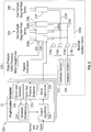
FIG. 2 shows a schematic diagram of a flight system for operating a rotary-wing aircraft such as the exemplary rotary-wing aircraft ofFIG. 1 ; and -
FIG. 3 shows a flowchart illustrating a method of flying an impaired rotary-wing aircraft. - Referring now to the Figures, where the invention will be described with reference to specific embodiments, without limiting same,
FIG. 1 schematically illustrates a conventionalrotary wing aircraft 100 having amain rotor assembly 112. Theaircraft 100 includes anairframe 114 having an extendingtail 116 which mounts an anti-torque system, such as atail rotor assembly 118. Themain rotor assembly 112 is driven about an axis of rotation through a transmission (illustrated schematically at 120) by one ormore engines 122. Themain rotor assembly 112 includes a plurality ofrotor blades 124 mounted to arotor hub 126, and aswashplate 128 that is used to affect a state or orientation of therotor blades 124. Therotor blades 124 can have a variable pitch that can be used to affect pitch and roll angles of theaircraft 100 as well as velocity of theaircraft 100. The pitch of therotor blades 124 can be controlled by a collective control or by a cyclic control. In various embodiment, themain rotor assembly 112 and thetail rotor assembly 118 are powered by respective servo motors, which in turn are powered by hydraulic systems onboard theaircraft 100. Theaircraft 100 is a fly-by-wire aircraft that implements control laws for flying the aircraft in response to a pilot input. -
Aircraft 100 includes aflight control system 70 for controlling flight of theaircraft 100. In particular, theflight control system 70 includes a processor (not shown) that executes a program that determines an effective flight envelope based on a condition of the hydraulic system of the aircraft and enforces the effective flight envelope against pilot inputs and sensor feedbacks. When a pilot provides a command for flying the aircraft outside of the effective flight envelope, theflight control system 70 implements a set of control laws that maintain the aircraft within the effective flight envelope. A detailed discussion of theflight control system 70 is provided below with respect toFIG. 2 . -
FIG. 2 shows a schematic diagram of aflight system 200 for operating a rotary-wing aircraft such as the exemplary rotary-wing aircraft 100 ofFIG. 1 . Theflight system 200 includes flight components andhardware 202 that operate to provide flight to theaircraft 100 and aflight control system 70 that controls operation of the flight components andhardware 202. The flight components andhardware 202 include amain rotor system 204, atail rotor 206 andhydraulic systems main rotor system 204 andtail rotor system 206 by hydraulic power or hydraulic pressure. Themain rotor system 204 includes threemain rotor servos main rotor system 204. Themain rotor servos tail rotor system 206 includes a singletail rotor servo 210 which operates to provide a rotation at thetail rotor system 206 and which also operates on hydraulic power. In one embodiment, themain rotor servos tail rotor servos 210 can be dual hydraulic stage servos. It is to be understood that themain rotor system 204 andtail rotor system 206 can also have any number of servo motors powered by any number of hydraulic servo stages in different embodiments. - Two hydraulic systems are used to power the
main rotor servos tail rotor servo 210. A firsthydraulic system 212 provides hydraulic power to each of themain rotor servos first fluid line 220a. Afirst valve 216a in thefirst fluid line 220b controls the flow of fluid from the firsthydraulic system 212 to themain rotor servos hydraulic system 212 provides hydraulic power to thetail rotor servo 210 viasecond fluid line 220b. Asecond valve 216b in thesecond fluid line 220b controls flow of fluid from the firsthydraulic system 212 to thetail rotor servo 210. In various embodiments, thefirst valve 216a andsecond valve 216b are hydraulic isolation valves. - A second
hydraulic system 214 provides hydraulic power to each of themain rotor servos tail rotor servo 210. The secondhydraulic system 214 provides redundancy to the firsthydraulic system 212 so that the aircraft can remain in flight in case of a failure of either the firsthydraulic system 212 or the secondhydraulic system 214. The secondhydraulic system 214 provides fluid to each of themain rotor servos third fluid line 222a. Athird valve 218a in thethird fluid line 222a controls the flow of fluid from the secondhydraulic system 214 to themain rotor servos hydraulic system 214 provides fluid to thetail rotor servo 210 via afourth flow line 218b. Afourth valve 222b in thefourth flow line 218b controls the flow of fluid from the secondhydraulic system 214 to thetail rotor 210. -
Sensors servo motors servo motors Sensors servo motor 208a for illustrative purposes only. It is to be understood thatadditional sensors servo motors sensor 224 measures at least one of a chamber pressure of a servo motor, a pressure difference (delta pressure) in both stages of each servo motor, or a strain on the servo motor. Measurements from thissensor 204 indicate a load on the servo motor. The delta pressure can be used to determine a degree of extension or retraction of a piston in the chamber of a servo motor. The strain measurements can be used to monitor a load on theservo motor 208a.Sensor 224 can be a pressure sensor or a strain gauge, depending on the type of parameter being measured. These measurements can be provided to theflight control system 70 which determines and/or detects the loads on the servomotor.Sensor 226 can measure a hydraulic pressure in a chamber ofservo motor 208a. These measurements can be provided to theflight control system 70 which identifies whether theservo motor 208a has full hydraulic pressure or determines which servo motor is experiencing a pressure loss. - The
flight control system 70 flies theaircraft 100 according to the pilot's inputs, taking into account the parameter measurements received at theflight control system 70 and the resulting effective flight envelope. In one embodiment, theflight control system 70 receives pilot input and compares the resulting actions requested by the pilot to a flight envelope of the aircraft. When the actions requested by the pilot are outside of the flight envelope, theflight control system 70 provides a different set of command to the flight components andhardware 202 in order to maintain theaircraft 100 within the flight envelope of the aircraft. Theflight control system 70 can also determine a flight envelope that is suitable for theaircraft 100 based on the measurements fromsensors - The
fight control system 70 includes acontrol algorithm 230, aservo command module 232 and a flightenvelope restrictions module 234. Theenvelope restrictions module 234 defines and/or calculates one or more flight envelopes of theaircraft 100. Thecontrol algorithm 230 receives pilot input and implements control laws to provide a flight command for theaircraft 100 that for producing an action at theaircraft 100 corresponding to the pilot input. Thecontrol algorithm 230 compares an action based on the pilot's input to a flight envelope received from theenvelope restrictions module 234. When the determined action at theaircraft 100 lies outside of the flight envelope, thecontrol algorithm 230 applies a different set of control laws to the pilot's input to generate flight commands which fly theaircraft 100 within the flight envelope received from theenvelope restrictions module 234. Thecontrol algorithm 230 provides the flight commands to theservo command module 232. Theservo command module 232 generates servo commands for controlling the servo motors and provides the servo commands to theservo motors - The
flight control system 70 further includes a servoload detection module 236 and servo hydraulicpressure detection module 238. The servoload detection module 236 receives parameter measurements fromsensors 224 and determines a load on the servo motors based on the parameter (e.g., at least one of chamber pressure, delta pressure, strain gauge force measurements). The servo hydraulicpressure detection module 238 receives parameter measurements fromsensors 226 and identifies pressure loss at one or more of the servo motor of themain rotor system 204 and/ortail rotor system 206. The load on the servo motors and the hydraulic pressure in the servo motor are provided to theenvelope restrictions module 234. Theenvelope restrictions module 234 identifies impaired servo motors and determines from the load on the servo motors and the hydraulic pressure in the servo motors a change that is to be made to the one or more flight envelopes. Theenvelope restriction module 234 includes a nominal flight envelope that corresponds to flight of the aircraft at 100% capacity (i.e., with the hydraulic systems and rotor systems able to operate at full capacity). When theenvelope restriction module 234 receives a notification of a loss of stage pressure or other hydraulic problem, theenvelope restriction module 234 changes the flight envelope to correspond to the capabilities of the impaired flight components andhardware 202 indicated by the measured parameter. - In one embodiment, the
envelope restriction module 234 may have stored therein a database of one or more flight envelopes for use under reduced capacity, with each stored flight envelope corresponding to a selected state of the hydraulic power system. For example, the flight envelope can have an assigned range of values for the measured parameters and is therefore selected when the measured parameter is within the assigned range of values. Therefore theenvelope restriction module 234 selects the flight envelope from the database based on the measure parameter. It is to be understood that the measured parameter can be a plurality of measured parameters and the stored flight envelopes can be selected based on a range of values for each of the measured parameters. - In another embodiment, the
envelope restriction module 234 calculates an effective flight envelope based on the parameter measurements. In one embodiment, the parameter measurements can be used along with the nominal flight envelope of the aircraft in order to calculate the effective flight envelope. The effective flight envelope can be calculated dynamically and can be changed when a condition of the hydraulic power system changes. Theenvelope restriction module 234 can make calculations on a periodic basis or when triggered by a signal. Therefore, when a condition of the hydraulic systems improves, the flight envelope can be changed to provide more capabilities to theaircraft 100. -
FIG. 3 shows aflowchart 300 illustrating a method of flying a rotary-wing aircraft, as described herein. Inbox 302, sensors measure an impaired parameter of the hydraulic system. Inbox 304, the envelope restrictions module determines an effective flight envelope of the aircraft based on a condition of the hydraulic system indicated by the parameter. Inbox 306, a pilot's input is received at theflight control system 70. For purposes of the invention, the pilot's input requests an action at the aircraft that is outside of the effective flight envelope of the aircraft. Inbox 308, the control laws generate a flight command in response to the pilot's input to fly the aircraft within the effective flight envelope. - While the invention has been described in detail in connection with only a limited number of embodiments, it should be readily understood that the invention is not limited to such disclosed embodiments. Rather, the invention can be modified to incorporate any number of variations, alterations, substitutions or equivalent arrangements not heretofore described, but which are commensurate with the spirit and scope of the invention. Additionally, while various embodiments of the invention have been described, it is to be understood that aspects of the invention may include only some of the described embodiments. Accordingly, the invention is not to be seen as limited by the foregoing description.
Claims (15)
- A system for flying a rotary-wing aircraft, comprising:a hydraulic system for providing hydraulic power to a rotor system of the aircraft;a sensor that measures a parameter of the hydraulic system;a processor configured to:determine a condition of the hydraulic system from the parameter, andfly the aircraft within an effective flight envelope that is based on the condition of the hydraulic system.
- The system of claim 1, wherein the parameter is indicative of a condition of a motor of the hydraulic system and the processor is further configured to determine the effective flight envelope based on the condition of the servo motor.
- The system of claim 1 or 2, wherein the processor is further configured to:receive a pilot input requesting operation of the aircraft outside of the effective flight envelope; andgenerate a flight command in response to the pilot input to fly the aircraft within the effective flight envelope.
- The system of one of claims 1-3, wherein the processor is further configured to alter the flight envelope from a nominal flight envelope to the effective flight envelope.
- The system of one of claims 1-4, wherein the processor is further configured to select the effective flight envelope from a database of flight envelopes.
- The system of claim 5, wherein the processor is further configured to select the effective flight envelope from the database based on when a value of the measured parameter is within a range corresponding to the effective flight envelope.
- The system of one of claims 1-6, wherein the processor is further configured to calculate the effective flight envelope dynamically based on a value of the measured parameter.
- The system of one of claims 1-7, wherein the parameter is at least one of a load on the aircraft and a hydraulic pressure of the hydraulic system.
- A rotary-wing aircraft, comprising:a servo system for actuating a rotor of the rotary-wing aircraft;a hydraulic system for powering the servo system;a sensor that measures a parameter of the hydraulic system; anda processor configured to:determine a condition of the hydraulic system from the parameter, andenforce on the aircraft an effective flight envelope that is based on the condition of the hydraulic system.
- The rotary-wing aircraft of claim 9, wherein the parameter is indicative of a condition of a servo motor of the hydraulic system and the processor is further configured to determine the effective flight envelope based on the condition of the servo motor.
- The rotary-wing aircraft of claim 9 or 10, wherein the processor is further configured to:receive a pilot input requesting operation of the aircraft outside of the effective flight envelope; andgenerate a flight command in response to the pilot input to fly the aircraft within the effective flight envelope.
- The rotary-wing aircraft of one of claims 1-11, wherein the processor is further configured to alter the flight envelope from a nominal flight envelope to the effective flight envelope.
- The rotary-wing aircraft of one of claims 1-12, wherein the processor is further configured to select the effective flight envelope from a database of flight envelopes when a value of the parameter is within a range assigned to the effective flight envelope.
- The rotary-wing aircraft of one of claims 1-13, wherein the processor is configured to calculate the effective flight envelope dynamically based on a value of the measured parameter.
- The rotary-wing aircraft of one of claims 1-14, wherein the parameter is at least one of a load on the aircraft and a hydraulic pressure of the hydraulic system.
Applications Claiming Priority (1)
| Application Number | Priority Date | Filing Date | Title |
|---|---|---|---|
| US15/696,345 US11442446B2 (en) | 2017-09-06 | 2017-09-06 | Automatic envelope limiting based on detected hydraulic failures |
Publications (1)
| Publication Number | Publication Date |
|---|---|
| EP3453611A1 true EP3453611A1 (en) | 2019-03-13 |
Family
ID=63491455
Family Applications (1)
| Application Number | Title | Priority Date | Filing Date |
|---|---|---|---|
| EP18192369.9A Withdrawn EP3453611A1 (en) | 2017-09-06 | 2018-09-04 | Automatic envelope limiting based on detected hydraulic failures |
Country Status (2)
| Country | Link |
|---|---|
| US (1) | US11442446B2 (en) |
| EP (1) | EP3453611A1 (en) |
Citations (4)
| Publication number | Priority date | Publication date | Assignee | Title |
|---|---|---|---|---|
| US5819188A (en) * | 1995-06-07 | 1998-10-06 | Aurora Flight Sciences Corporation | Fault tolerant automatic control system utilizing analytic redundancy |
| US6189836B1 (en) * | 1998-09-25 | 2001-02-20 | Sikorsky Aircraft Corporation | Model-following control system using acceleration feedback |
| US20090177292A1 (en) * | 2008-01-03 | 2009-07-09 | Mossman David C | Control system actuation fault monitoring |
| US20130334361A1 (en) * | 2011-07-12 | 2013-12-19 | Bell Helicopter Textron Inc. | System and method for limiting cyclic control inputs |
Family Cites Families (10)
| Publication number | Priority date | Publication date | Assignee | Title |
|---|---|---|---|---|
| US3454319A (en) | 1967-11-03 | 1969-07-08 | United Service Equipment Co In | Self-leveling lifter |
| US4904999A (en) | 1983-03-28 | 1990-02-27 | The Boeing Company | Fault monitoring system for aircraft power control units |
| US5977648A (en) | 1996-10-21 | 1999-11-02 | Sundstrand Corporation | Hydraulically driven low reactance, large air gap permanent magnet generator and voltage regulation system for use therewith |
| DE19855404A1 (en) * | 1998-12-01 | 2000-06-15 | Daimler Chrysler Ag | Hydraulic power steering for motor vehicles |
| US6735500B2 (en) * | 2002-06-10 | 2004-05-11 | The Boeing Company | Method, system, and computer program product for tactile cueing flight control |
| US8195346B1 (en) * | 2009-01-21 | 2012-06-05 | Garmin International, Inc. | Envelope protection for mechanically-controlled aircraft |
| EP2543589B1 (en) * | 2011-07-06 | 2018-09-05 | Airbus Helicopters | Primary flight controls |
| US10843796B2 (en) * | 2012-02-10 | 2020-11-24 | Merlin Technology, Inc. | Rotorcraft advanced autopilot control arrangement and methods |
| US10196131B2 (en) * | 2016-02-16 | 2019-02-05 | The Boeing Company | Hydraulic system and method for an aircraft flight control system |
| FR3053413B1 (en) * | 2016-06-29 | 2019-03-29 | Airbus Helicopters | DOUBLE HYDRAULIC CIRCUIT WITH PRESSURE REGULATION |
-
2017
- 2017-09-06 US US15/696,345 patent/US11442446B2/en active Active
-
2018
- 2018-09-04 EP EP18192369.9A patent/EP3453611A1/en not_active Withdrawn
Patent Citations (4)
| Publication number | Priority date | Publication date | Assignee | Title |
|---|---|---|---|---|
| US5819188A (en) * | 1995-06-07 | 1998-10-06 | Aurora Flight Sciences Corporation | Fault tolerant automatic control system utilizing analytic redundancy |
| US6189836B1 (en) * | 1998-09-25 | 2001-02-20 | Sikorsky Aircraft Corporation | Model-following control system using acceleration feedback |
| US20090177292A1 (en) * | 2008-01-03 | 2009-07-09 | Mossman David C | Control system actuation fault monitoring |
| US20130334361A1 (en) * | 2011-07-12 | 2013-12-19 | Bell Helicopter Textron Inc. | System and method for limiting cyclic control inputs |
Also Published As
| Publication number | Publication date |
|---|---|
| US11442446B2 (en) | 2022-09-13 |
| US20190072952A1 (en) | 2019-03-07 |
Similar Documents
| Publication | Publication Date | Title |
|---|---|---|
| US11208205B2 (en) | System and method for rotorcraft autorotation entry assist | |
| US11685523B2 (en) | System and method for monitoring aircraft pilot control position and providing a retrim prompt | |
| CN108502196B (en) | Reverse haptic cues for rotorcraft rotor overspeed protection | |
| US11117653B2 (en) | System and method for tactile cueing through rotorcraft pilot controls using variable friction and force gradient | |
| EP3578458B1 (en) | System and method for rotorcraft height control | |
| EP3560824B1 (en) | System and method for automatic rotorcraft tail strike protection | |
| EP3620373A1 (en) | Stuck in detent monitors for collective and cyclic sticks | |
| US10611492B2 (en) | System and method for tail rotor margin awareness | |
| EP2821341A1 (en) | Inceptor and method for operating an inceptor | |
| EP3569497B1 (en) | System and method for tactile cueing through rotorcraft pilot controls using variable friction and force gradient | |
| EP3627271B1 (en) | System and method for controlling rotorcraft | |
| CN110498038A (en) | Rotorcraft and its control method | |
| US20160355251A1 (en) | Inceptor and method for operating an inceptor | |
| EP3197774B1 (en) | Steady state differential roll moment control with automated differential lateral control | |
| US20190144101A1 (en) | Open and closed control of actuators, which drive aerodynamic control surfaces of an aircraft | |
| EP3453611A1 (en) | Automatic envelope limiting based on detected hydraulic failures | |
| Rajendran et al. | Fault tolerant control of a small helicopter with tail rotor failures in forward flight |
Legal Events
| Date | Code | Title | Description |
|---|---|---|---|
| PUAI | Public reference made under article 153(3) epc to a published international application that has entered the european phase |
Free format text: ORIGINAL CODE: 0009012 |
|
| AK | Designated contracting states |
Kind code of ref document: A1 Designated state(s): AL AT BE BG CH CY CZ DE DK EE ES FI FR GB GR HR HU IE IS IT LI LT LU LV MC MK MT NL NO PL PT RO RS SE SI SK SM TR |
|
| AX | Request for extension of the european patent |
Extension state: BA ME |
|
| 17P | Request for examination filed |
Effective date: 20190913 |
|
| RBV | Designated contracting states (corrected) |
Designated state(s): AL AT BE BG CH CY CZ DE DK EE ES FI FR GB GR HR HU IE IS IT LI LT LU LV MC MK MT NL NO PL PT RO RS SE SI SK SM TR |
|
| 17Q | First examination report despatched |
Effective date: 20200422 |
|
| STAA | Information on the status of an ep patent application or granted ep patent |
Free format text: STATUS: THE APPLICATION IS DEEMED TO BE WITHDRAWN |
|
| 18D | Application deemed to be withdrawn |
Effective date: 20200903 |