EP3453579A1 - Locking device - Google Patents
Locking device Download PDFInfo
- Publication number
- EP3453579A1 EP3453579A1 EP18183354.2A EP18183354A EP3453579A1 EP 3453579 A1 EP3453579 A1 EP 3453579A1 EP 18183354 A EP18183354 A EP 18183354A EP 3453579 A1 EP3453579 A1 EP 3453579A1
- Authority
- EP
- European Patent Office
- Prior art keywords
- lock cylinder
- locking device
- cylinder
- housing
- support member
- Prior art date
- Legal status (The legal status is an assumption and is not a legal conclusion. Google has not performed a legal analysis and makes no representation as to the accuracy of the status listed.)
- Granted
Links
- 230000008878 coupling Effects 0.000 claims abstract description 28
- 238000010168 coupling process Methods 0.000 claims abstract description 28
- 238000005859 coupling reaction Methods 0.000 claims abstract description 28
- 230000005540 biological transmission Effects 0.000 claims description 2
- 238000006073 displacement reaction Methods 0.000 claims 1
- 230000008901 benefit Effects 0.000 description 4
- ORQBXQOJMQIAOY-UHFFFAOYSA-N nobelium Chemical compound [No] ORQBXQOJMQIAOY-UHFFFAOYSA-N 0.000 description 4
- 230000009471 action Effects 0.000 description 3
- 230000007246 mechanism Effects 0.000 description 3
- 239000011324 bead Substances 0.000 description 2
- 230000006835 compression Effects 0.000 description 2
- 238000007906 compression Methods 0.000 description 2
- 238000009434 installation Methods 0.000 description 2
- 230000003993 interaction Effects 0.000 description 2
- 230000014759 maintenance of location Effects 0.000 description 2
- 239000007858 starting material Substances 0.000 description 2
- 230000000694 effects Effects 0.000 description 1
- 210000003746 feather Anatomy 0.000 description 1
- 230000000284 resting effect Effects 0.000 description 1
Images


Classifications
-
- B—PERFORMING OPERATIONS; TRANSPORTING
- B60—VEHICLES IN GENERAL
- B60R—VEHICLES, VEHICLE FITTINGS, OR VEHICLE PARTS, NOT OTHERWISE PROVIDED FOR
- B60R25/00—Fittings or systems for preventing or indicating unauthorised use or theft of vehicles
- B60R25/01—Fittings or systems for preventing or indicating unauthorised use or theft of vehicles operating on vehicle systems or fittings, e.g. on doors, seats or windscreens
- B60R25/02—Fittings or systems for preventing or indicating unauthorised use or theft of vehicles operating on vehicle systems or fittings, e.g. on doors, seats or windscreens operating on the steering mechanism
- B60R25/021—Fittings or systems for preventing or indicating unauthorised use or theft of vehicles operating on vehicle systems or fittings, e.g. on doors, seats or windscreens operating on the steering mechanism restraining movement of the steering column or steering wheel hub, e.g. restraining means controlled by ignition switch
Definitions
- the invention relates to a locking device for locking a functionally essential component, in particular a steering column or a gearshift lever, of a vehicle according to the preamble of the independent claim.
- lock cylinder In known locking devices of functionally essential components, such. As steering columns or gear shift levers, in vehicles lock cylinder are often used to lock the functionally essential component after parking the vehicle.
- the locking devices can thus serve as a safeguard against unauthorized use of the vehicle.
- the lock cylinder can be mounted in two different rotational positions within a housing of the locking devices, but the lock cylinder itself is not constructed completely rotationally symmetrical, so that elements of the lock cylinder, in particular, a lock pin retention system integrated in the lock cylinder, depending on the rotational position of the assembled lock cylinder subject to a higher mechanical wear.
- a driver for the key withdrawal protection which is usually formed of plastic and mechanically operated or moved by the imported key, be subjected to greater stress, whereby the locking pin retention system can be disturbed in its function.
- the invention is therefore based on an object at least partially overcome a known from the prior art disadvantage in locking devices one functionally essential component, in particular a steering column or a gearshift lever, a vehicle.
- a fitter should be supported or relieved during assembly to quickly and easily find the correct position of the lock cylinder in the housing.
- the invention provides for this purpose a locking device for locking a functionally essential component, in particular a steering column or a gearshift lever, a vehicle with the features of independent claim 1, in particular from the characterizing part ready.
- the invention provides a locking device for locking a functionally essential component, in particular a steering column or a gearshift lever, of a vehicle, comprising: a housing for receiving a lock cylinder, which serves for actuating a locking element of the functionally essential component, a support element for supporting the lock cylinder in the housing, wherein the support member rotatably (and in particular axially displaceable) is mounted in the housing, wherein the lock cylinder has a rotatable cylinder core, which is connectable to a rotatable coupling (at least in normal operation of the locking device), which can be brought into operative connection with the locking element, and wherein the coupling axially (ie, along a longitudinal direction of extension of the lock cylinder) is supported on the support member (so that the clutch is freely rotatable and by the support member axially, preferably downwardly away from the lock cylinder, movable).
- an assembly unit according to the invention is provided to fix the lock cylinder (for normal operation of the locking device)
- the housing according to the invention can also accommodate a start switch, which can be operated by means of the clutch, for example by turning the clutch.
- the starter switch can be protected inside the housing to ensure that only the lock cylinder suitable bowl or only the authorized user can perform the switching operation.
- This is called an ignition lock.
- the ignition lock forms a steering wheel lock.
- the locking device according to the invention may be referred to as a steering wheel lock.
- the locking device according to the invention which comprises the mechanical lock cylinder, may be referred to as a mechanical steering wheel lock.
- the housing according to the invention can be arranged laterally on the steering column or on the center console or form part of the steering column cover or the center console.
- the support member according to the invention rotatably in the housing, that is not rotatable relative to the housing stored.
- the support member is axially displaceable supported on the housing, for example.
- a spring Preferably, the support member from an operating position in a retracted position against the action of the spring force in the housing interior, ie be pressed away from the lock cylinder.
- the lock cylinder is in turn axially immovable relative to the housing arranged thereon.
- the lock cylinder has a rotatable cylinder core and a non-rotatable in normal operation of the locking device cylinder sleeve.
- the overload clutch moves the support member away from the lock cylinder into the interior of the housing, taking with the clutch, because the clutch is axially supported on the support member. Consequently, at least during normal operation of the locking device an operative connection of the cylinder core is made with the clutch, wherein in a burglary case and a violent rotation of the lock cylinder, the operative connection of the cylinder core is released with the clutch.
- a key withdrawal lock is arranged, which may protrude to one side of the lock cylinder when a key is received in the cylinder core. If the lock cylinder is installed in a wrong position in the housing, it can lead to increased wear on the elements of the key withdrawal lock.
- the idea of the invention lies in the fact that an assembly unit is provided, so that the lock cylinder can be mechanically fixed or mounted in only one way, ie in only one correct installation position in the housing of the locking device.
- the mounting unit allows intuitive installation. This relieves the fitter and protects the locking device against wear. Thus, the correct operation of the locking device can be ensured and the life of the locking device can be increased.
- the mounting unit can have at least a few corresponding means which can mark the correct mounting position in interaction. By establishing a connection between the corresponding means of the assembly unit, the fitter can receive a haptic feedback on the accuracy of the assembly.
- the corresponding means of the assembly unit between the housing and the lock cylinder, between the support member and the lock cylinder (as part of an overload protection) or between the clutch and the lock cylinder can be provided.
- the mounting unit can be used directly in existing Functional elements of the locking device (eg. Overload coupling between the support member and the lock cylinder) are integrated and expand their functionality, but without complicating the structure of the locking device.
- the invention thus provides a locking device which allows a correct, simple and intuitive mounting of a lock cylinder within a housing of the locking device in only a predetermined mounting position.
- the mounting unit is designed in the form of an overload protection for the lock cylinder.
- the overload protection usually has two pairs of corresponding elements, mostly grooves and corresponding cams, between the lock cylinder and the support member, which are in mechanical operative connection with each other in normal operation of the locking device. Upon violent rotation of the lock cylinder, the mechanical operative connection between the elements of the overload protection is released to prevent an effect transfer from the lock cylinder to the clutch and finally to the locking element.
- These elements of the overload protection are therefore advantageously suitable for marking the correct mounting position of the lock cylinder within the housing, when a pair of them carries characteristic features or differs from the other pair.
- the functionality of the overload protection can be extended with an auxiliary assembly function in addition to an overload function, without preventing the overload protection in their overload function.
- a simply constructed, improved locking device can be provided.
- the difference features on the elements of the overload protection can also be retrofitted to upgrade existing locking devices.
- an overload protection between the support member and the lock cylinder is provided to move the support member with the clutch axially away from the lock cylinder at a violent rotation of the lock cylinder in a burglary case and the cylinder core of to decouple the clutch.
- an overload protection may be advantageous to decouple the locking mechanism from Lock cylinder to allow.
- the mounting unit at least a first mounting means or a second, in particular different from the first, mounting means, which / which in only a predetermined orientation of the lock cylinder with at least one corresponding first positioning means or a second, in particular of the first different, positioning, on the lock cylinder in mechanical operative connection can be brought.
- the correct mounting position of the lock cylinder in the housing of the locking device can be clearly specified.
- the lock cylinder at least a first positioning means or a second, in particular from the first different, positioning in the form of, preferably two different widths or high, cams or grooves, in particular on one of the clutch facing end face or on a lateral surface of the lock cylinder, is formed.
- first positioning means or a second in particular from the first different, positioning in the form of, preferably two different widths or high, cams or grooves, in particular on one of the clutch facing end face or on a lateral surface of the lock cylinder, is formed.
- the mounting unit in particular the overload protection, at least one first mounting means or a second, preferably different from the first, mounting means in the form of, preferably two different widths or depths, grooves or cams on a the Has lock cylinder facing side of the support element.
- the position between the lock cylinder and the support element is advantageously suitable for providing the mounting unit at the position.
- an overload protection is arranged between the lock cylinder and the support element, which already has corresponding elements that can be easily modified to allow the fixing of the lock cylinder in only one position on the support element.
- the support element is in the form of a groove plate or a cam disc.
- the support member may form a seat for the lock cylinder, so that the lock cylinder can be easily positioned on the support member.
- the mounting unit has at least a first mounting means or a second, in particular different from the first mounting means in the form of, preferably two different widths, in particular axial, grooves or cams in the housing.
- the invention can provide that at least one first positioning means in the form of a connecting cam on the cylinder core is formed on the lock cylinder, wherein in particular the mounting unit has at least one first mounting means in the form of a groove in the coupling.
- the operative connection of the lock cylinder with the locking element is made via the coupling and the cylinder core, the cylinder core has for this purpose a connecting cam, which can be inserted in a corresponding receptacle of the coupling to produce a rotationally fixed connection of the cylinder core with the coupling.
- a connecting cam which can be inserted in a corresponding receptacle of the coupling to produce a rotationally fixed connection of the cylinder core with the coupling.
- the invention may provide for a locking device that at least one first positioning means or a second, in particular different from the first, positioning on the lock cylinder at least one, preferably two differently oriented, Aushebeschrägen.
- a locking device that at least one first positioning means or a second, in particular different from the first, positioning on the lock cylinder at least one, preferably two differently oriented, Aushebeschrägen.
- Aushebeschrägen the lock cylinder, for example.
- the correct position of the lock cylinder can be clearly marked in the housing , This represents a particularly elegant and easily realizable possibility of how the assembly unit, regardless of their position, can specify the correct position of the lock cylinder in the housing.
- the invention may provide for a locking device that at least one first mounting means or a second, in particular different from the first, mounting means of the mounting unit has at least one, preferably two differently oriented, Ausheberampen.
- a locking device that at least one first mounting means or a second, in particular different from the first, mounting means of the mounting unit has at least one, preferably two differently oriented, Ausheberampen.
- the support member is longitudinally displaceable between an operating position and a retracted position in the housing, wherein in the operating position of the support member of the lock cylinder is fixed to the support member by the mounting unit to torque transmission between the cylinder core and allow the clutch, and in the retracted position of the support member of the lock cylinder axially spaced to the support element to decouple the cylinder core from the coupling.
- the Aushebeschrägen can free from the corresponding seats of the overload clutch, whereby the support element is moved backwards and away from the lock cylinder. The support element also pulls the clutch away from the lock cylinder. Further manipulation of the lock cylinder would be pointless from this point, since no rotation of the lock cylinder causes a transfer to the clutch.
- the invention can provide a spring element in a locking device in order to act on the support element resiliently, in particular with a spring force from a retracted position into an operating position.
- a fixation of the lock cylinder on the support element can be made possible, which is solvable by a violent actuation of the lock cylinder against the spring force of the spring element.
- the safety in the vehicle can be increased to prevent the functionally essential component unauthorized unlocked and the vehicle can be steered.
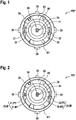
- the FIG. 1a shows a known locking device 100 * for locking a functionally essential component 101 (shown in the FIG. 3a ), as. z.
- a steering column or a gearshift lever for a vehicle that is designed with a lock cylinder 20.
- the lock cylinder 20 serves for the mechanical actuation of an example in the FIG. 3a illustrated locking element 102, which may be in the form of a locking bolt and which can lock the functionally essential component 101 after parking the vehicle.
- a rotatable cylinder core 24 of the lock cylinder 20 is for this purpose rotatably connected to a clutch 40 by a molded on the cylinder core 24 connecting cam 25 is inserted into a groove 41 in the coupling 40.
- the coupling 40 can transmit a rotational movement of the cylinder core 24 of the lock cylinder 20 to a start switch, not shown, and to the locking element 102.
- the lock cylinder 20 is supported on a support element 30, for example.
- a support element 30 In the form of a Nuten- or a cam disc, which in turn rotatably and longitudinally displaceable in one housing 10 is received via one or more projections 35, which, as in the FIGS. 3a to 3c is shown, can be executed.
- On the support member 30 is the rotatable coupling 40 axially supported, so that the coupling 40 can be moved axially with the support member 30.
- the coupling 40 can be pushed away with the support member 30 from the lock cylinder 20 when an overload protection 23 is activated.
- the overload protection 23 is activated by a forced rotation of the lock cylinder 20.
- a locking device 100 * may be disadvantageous that the lock cylinder 20 can be mounted in two different rotational positions within the housing 10 of the locking device 100.
- the lock cylinder 20 itself is not completely rotationally symmetrical, elements of the lock cylinder 20, which protrude from its lateral surface E3 and thus come into contact with the housing 10, such.
- a simplicity not shown key removal fuse depending on the rotational position of the assembled lock cylinder 20 subject to higher mechanical wear.
- the locking device 100 * can be disturbed in its function.
- FIG. 2 shows a locking device 100 according to the invention for locking a functionally essential component 101, in particular a steering column or a gearshift lever, a vehicle, which by way of example in the FIG. 3a is shown.
- the locking device 100 according to the invention is designed such that the lock cylinder 20 can be mounted in only one predetermined mounting position A in the housing 10 or on a support member 30, for example. In the form of a cam or a Nutenin supported.
- the locking device 100 further comprises a housing 10 in which the support member 30 may be rotatably mounted and axially displaceable, as described in the following FIGS. 3a to 3c clarify.
- the lock cylinder 20 according to the invention also comprises a rotatable cylinder core 24 which is provided with a rotatable coupling 40 at least in normal operation of the locking device 100 or in an operating position I of the support member 30 is connectable, wherein the operating position I of the support member 30 in the FIG. 3a is shown.
- the lock cylinder 20 has a lateral surface E3, which is received in a cylindrical receptacle of the housing 10. Outwardly a front E2 of the lock cylinder 20 is aligned, which allows a recording of a key in the cylinder core 24.
- the coupling 40 can be brought into operative connection with a locking element 102 via a closing mechanism not shown for reasons of simplicity, which can be in the form of a locking bolt and which can dive into a recess on the functionally essential component 101 in order to lock the functionally essential component 101.
- the coupling 40 is axially supported at least in one direction on the support member 30, so that the clutch 40 is indeed freely rotatable, but axially together with the support member 30, preferably away from the lock cylinder 20, is movable.
- an assembly unit M is provided according to the invention.
- the housing 10 according to the invention can furthermore accommodate a starter switch, not shown, which can be actuated by means of the clutch 40.
- This is called an ignition lock.
- the ignition lock forms a steering wheel lock.
- the locking device 100 according to the invention may be referred to as a steering wheel lock, in particular a mechanical steering wheel lock.
- the start switch can be protected inside the housing 10 behind the lock cylinder 20 and behind the lock mechanism are arranged so that the start switch can not be manipulated from the outside. Only when a bowl matching the lock cylinder 20 is used can tumblers, not shown in the figures, be sorted within the cylinder core 24 to allow the cylinder core 24 to rotate relative to a cylinder sleeve.
- the housing 10 according to the invention can be laterally on the steering column or on the Center console be arranged or form part of the steering column panel or the center console.
- the lock cylinder 20 is in turn arranged axially immovable relative to the housing 10. In a burglary case, if a burglary tool, for example. A screwdriver is used, not all tumblers within the cylinder core 24 are sorted correctly, so that the cylinder core 24 remains rotatably connected to the cylinder sleeve.
- an overload clutch 23 is provided which separates the operative connection between the lock cylinder 20 and the support member 30 and thus between the lock cylinder 20 and the clutch 40.
- the overload clutch 23 moves the support member 30 away from the lock cylinder 20 into the interior of the housing 10 and thereby takes the clutch 40, because the clutch 40 is axially supported on the support member 30.
- the overload protection 23 comprises in the example of FIG. 2 two differently sized, for example. Different width, cam 21, 22 on the lock cylinder 20, in particular on one of the clutch 40 facing end face E1 of the lock cylinder 20, which in normal operation of the locking device 100 in two corresponding, also different width, cams 31, 32 within the Support element 30 are received.
- the invention recognizes that the means of overload protection 23 can be performed in pairs differently, to ensure that the lock cylinder 20 can be fixed in only one rotational position on the support member 30.
- the assembly unit M in the context of the invention within the overload protection 23rd be integrated.
- the functionality of the overload protection 23 can be extended with an assembly assistance function in addition to an overload function, without preventing the overload protection 23 in its overload function.
- a simply constructed, improved locking device 100 can be provided.
- the difference features on the elements of the overload protection 23 can also be retrofitted to upgrade existing locking devices 100.
- FIG. 2 shows a first embodiment of the mounting unit M according to the invention, in which the cams 21, 22 on the lock cylinder 20 and the grooves 31, 32 are formed on the support member 30 of different sizes.
- the grooves 21, 22 may be formed, wherein the support member 30, the corresponding cams 31, 32 may be formed as it FIGS. 3a to 3c demonstrate.
- the cams or the grooves 21, 22 on the lock cylinder 20 serve as positioning means P1, P2 of the mounting unit M, which can interact with corresponding mounting means M1, M2, for example.
- the mounting unit M In the form of grooves or cams 31, 32 on the support member 30, the mounting unit M.
- the support member 30 is received by means of projection-like bearing elements 35 in corresponding bearing grooves 15 within the housing 10 longitudinally displaceable.
- a stationary housing member 14 is mounted, between which and the support member 30, a spring 13, for example.
- a helical, compression spring is provided.
- the spring force F of the spring 13 ensures that the support member 30 can be pressed from the operating position I in the retracted position II.
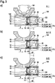
- FIG. 3a engage the cams 31, 32, which are, for example, formed on the support member 30, in corresponding grooves 21, 22 on the lock cylinder 20.
- FIG. 3b It is shown how the cams 31, 32 during a rotation of the lock cylinder 20 can move within the grooves 21, 22.
- the Figure 3c finally shows how the cams 31, 32nd outside the grooves 21, 22 lift out and thus can free.
- the distance d1 between the lock cylinder 20 and the support element 30, which is the usual distance during normal operation of the locking device 100, is increased to a distance d2 which is characteristic of an overload situation.
- the support member 30 is displaced so to a distance d2 from the lock cylinder 20 that the rotationally fixed connection of the clutch 40 and the cylinder core 24 is repealed.
- the mounting unit M is provided between the lock cylinder 20 and the support member 30 and integrated within the overload protection 23.
- FIGS. 4a and 4b show a further embodiment of a mounting unit according to the invention M.
- the mounting unit M may also be integrated within the overload protection 23.
- FIG. 4b shows further in a schematically illustrated radial sectional view that the support member 30 on the first mounting means M1 and / or on the second, different or even equal width mounting means M2, which may be formed both in the form of grooves and in the form of cams, two different aligned lifting ramps 31a, 31b, 32a, 32b may have.
- the lock cylinder 20 can come to rest in only one mounting position A on the support element 30, so that the Aushebeschrägen 21a, 21b, 22a, 22b can abut the Ausheberampen 31a, 31b, 32a, 32b.
- FIGS. 5a and 5b show a further embodiment of a mounting unit according to the invention M.
- the mounting unit M also this time only a correct mounting position A of the lock cylinder 20 on the support member 30 and is integrated within the overload protection 23.
- the support member 30 may also have only at one of the two mounting means M1, M2, for example.
- On the first mounting means M1 a corresponding recess as a Ausheberampe 31a. The bead fits in only one rotational position of the lock cylinder 20 relative to the support member 30 in the corresponding recess on the support member 30.
- the lock cylinder 20 can be properly mounted in only one mounting position A on the support member 30.
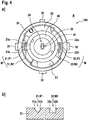
- the Figures 6a and 6b show a further embodiment of the mounting unit according to the invention M.
- the mounting unit M marks only a correct mounting position A of the lock cylinder 20 on the support member 30 and is integrated within the overload protection 23.
- the lock cylinder 20 may have different height, albeit equally wide, positioning means P1, P2, which may be formed either in the form of cams or in the form of grooves.
- the FIG. 6b shows further in a sectional view that the support member 30 may have two different depth, albeit equally wide, mounting means M1, M2, which may be formed both in the form of grooves and in the form of cams.
- FIG. 7 shows a further embodiment of the mounting unit according to the invention M.
- the mounting unit M between the lateral surface E3 of the lock cylinder 20 and the housing 10 is formed.
- One or more, for example, two, positioning P1, P2 may be provided on the lateral surface E3 of the lock cylinder 20, which may be the same or different widths, equal or underschlich long, cam-shaped or groove-shaped.
- Two, corresponding mounting means M1, M2 may be provided, which may also be formed differently wide or long and groove-shaped or cam-shaped. This also makes it possible for the positioning means or the positioning means P1, P2 in only one rotational position of the lock cylinder 20 with the corresponding mounting means M1, M2 can interact.
- FIGS. 8a and 8b show another possible embodiment of the mounting unit according to the invention M.
- the mounting unit M is arranged between the lock cylinder 20 and the clutch 40.
- a connecting cam 25 as a positioning means P1 of the mounting unit M is provided on the cylinder core 24, which can have two differently aligned Aushebeschrägen 25a, 25b.
- the connection cam 25 may be operatively connected to a groove 41 as a mounting means M1 of the mounting unit M, which may be formed with corresponding lift-off lamps 41a, 41b.
- the Aushebeschrägen 25a, 25b come in only one rotational position of the lock cylinder 20 for resting on the Ausheberampen 41a, 41b, whereby the correct mounting position A of the lock cylinder 20 can be clearly marked within the housing 10.
- FIGS. 9 and 10 show the lock cylinder 20 according to an embodiment of the invention according to the FIGS. 3a to 3c in different perspective views. From the FIG. 9 it can be seen that the support element 30 resiliently with the spring force F of the spring 13 from the retracted position II ( Figure 3c ) into the operating position I ( FIG. 3a ) can be applied.
- the spring 13 can be arranged between a housing element 14 which is stationary relative to the housing 10 and the support element 30.
- the FIG. 9 shows the spring 13 by way of example as a helical compression spring.
- the FIG. 10 shows in a perspective view of the bearing elements 35 which can be axially slidably received in corresponding bearing grooves 15 within the housing 10, which in the FIGS. 3a to 3c are shown.
Landscapes
- Engineering & Computer Science (AREA)
- Mechanical Engineering (AREA)
- Lock And Its Accessories (AREA)
Abstract
Die Erfindung betrifft eine Verriegelungsvorrichtung (100) zum Verriegeln eines funktionswesentlichen Bauteils (101), insbesondere einer Lenksäule oder eines Gangschalthebels, eines Fahrzeuges, aufweisend: ein Gehäuse (10) zur Aufnahme eines Schließzylinders (20), welcher zum Betätigen eines Verriegelungselementes (102) des funktionswesentlichen Bauteils (101) dient, ein Stützelement (30) zum Abstützen des Schließzylinders (20) im Gehäuse (10), wobei das Stützelement (30) drehfest im Gehäuse (10) gelagert ist, wobei der Schließzylinder (20) einen drehbaren Zylinderkern (24) aufweist, der mit einer drehbaren Kupplung (40) verbindbar ist, die in eine Wirkverbindung mit dem Verriegelungselement (102) bringbar ist, und wobei die Kupplung (40) axial am Stützelement (30) abgestützt ist. Hierzu ist erfindungsgemäß eine Montageeinheit (M) vorgesehen, um den Schließzylinder (20) in einer vorgegebenen Montageposition (A) innerhalb des Gehäuses (10) zumindest formschlüssig am Stützelement (30) zu fixieren.

Description
Die Erfindung betrifft eine Verriegelungsvorrichtung zum Verriegeln eines funktionswesentlichen Bauteils, insbesondere einer Lenksäule oder eines Gangschalthebels, eines Fahrzeuges nach dem Oberbegriff des unabhängigen Anspruches.The invention relates to a locking device for locking a functionally essential component, in particular a steering column or a gearshift lever, of a vehicle according to the preamble of the independent claim.
Bei bekannten Verriegelungsvorrichtungen von funktionswesentlichen Bauteilen, wie z. B. von Lenksäulen oder Gangschalthebeln, in Fahrzeugen werden oft Schließzylinder benutzt, um das funktionswesentliche Bauteil nach dem Abstellen des Fahrzeuges zu verriegeln. Die Verriegelungsvorrichtungen können somit als Sicherung gegen unbefugte Benutzung des Fahrzeuges dienen. Zurzeit besteht das Problem, dass der Schließzylinder in zwei unterschiedlichen Drehpositionen innerhalb eines Gehäuses der Verriegelungsvorrichtungen montiert werden kann, wobei jedoch der Schließzylinder selbst nicht vollständig rotationssymmetrisch aufgebaut ist, sodass Elemente des Schließzylinders, insbesondere eines im Schließzylinder integrierten Sperrbolzenrückhaltesystems, je nach Drehstellung des montierten Schließzylinders einem höheren mechanischen Verschleiß unterliegen. In einer falschen Position des Schließzylinders kann bspw. ein Mitnehmer für die Schlüsselabzugssicherung, der üblicherweise aus Kunststoff ausgebildet und von dem eingeführten Schlüssel mechanisch betätigt bzw. verschoben wird, stärker beansprucht werden, wodurch das Sperrbolzenrückhaltesystem in seiner Funktion gestört werden kann.In known locking devices of functionally essential components, such. As steering columns or gear shift levers, in vehicles lock cylinder are often used to lock the functionally essential component after parking the vehicle. The locking devices can thus serve as a safeguard against unauthorized use of the vehicle. At present, there is the problem that the lock cylinder can be mounted in two different rotational positions within a housing of the locking devices, but the lock cylinder itself is not constructed completely rotationally symmetrical, so that elements of the lock cylinder, in particular, a lock pin retention system integrated in the lock cylinder, depending on the rotational position of the assembled lock cylinder subject to a higher mechanical wear. In a wrong position of the lock cylinder can, for example, a driver for the key withdrawal protection, which is usually formed of plastic and mechanically operated or moved by the imported key, be subjected to greater stress, whereby the locking pin retention system can be disturbed in its function.
Der Erfindung liegt daher eine Aufgabe zugrunde, mindestens einen aus dem Stand der Technik bekannten Nachteil bei Verriegelungsvorrichtungen eins funktionswesentlichen Bauteils, insbesondere einer Lenksäule oder eines Gangschalthebels, eines Fahrzeuges zumindest zum Teil zu überwinden. Insbesondere ist es eine Aufgabe der vorliegenden Erfindung eine Verriegelungsvorrichtung zu schaffen, welche eine richtige Montage eines Schließzylinders innerhalb eines Gehäuses der Verriegelungsvorrichtung ermöglicht. Vorzugsweise soll ein Monteur bei der Montage unterstützt bzw. entlastet werden, um die richtige Position des Schließzylinders im Gehäuse schnell und einfach zu finden.The invention is therefore based on an object at least partially overcome a known from the prior art disadvantage in locking devices one functionally essential component, in particular a steering column or a gearshift lever, a vehicle. In particular, it is an object of the present invention to provide a locking device which allows a proper mounting of a lock cylinder within a housing of the locking device. Preferably, a fitter should be supported or relieved during assembly to quickly and easily find the correct position of the lock cylinder in the housing.
Die Erfindung stellt hierzu eine Verriegelungsvorrichtung zum Verriegeln eines funktionswesentlichen Bauteils, insbesondere einer Lenksäule oder eines Gangschalthebels, eines Fahrzeuges mit den Merkmalen des unabhängigen Anspruches 1, insbesondere aus dem kennzeichnenden Teil, bereit. Merkmale, die zu den einzelnen Ausführungsformen der erfindungsgemäßen Verriegelungsvorrichtung offenbart werden, können in der Weise miteinander kombiniert werden, dass bezüglich der Offenbarung zu den Ausführungsformen stets wechselseitig Bezug genommen wird bzw. werden kann.The invention provides for this purpose a locking device for locking a functionally essential component, in particular a steering column or a gearshift lever, a vehicle with the features of independent claim 1, in particular from the characterizing part ready. Features disclosed with respect to the individual embodiments of the locking device according to the invention may be combined with one another in such a way that reciprocal reference to the embodiments is always made.
Die Erfindung stellt eine Verriegelungsvorrichtung zum Verriegeln eines funktionswesentlichen Bauteils, insbesondere einer Lenksäule oder eines Gangschalthebels, eines Fahrzeuges bereit, aufweisend: ein Gehäuse zur Aufnahme eines Schließzylinders, welcher zum Betätigen eines Verriegelungselementes des funktionswesentlichen Bauteils dient, ein Stützelement zum Abstützen des Schließzylinders im Gehäuse, wobei das Stützelement drehfest (und insbesondere axial verschieblich) im Gehäuse gelagert ist, wobei der Schließzylinder einen drehbaren Zylinderkern aufweist, der mit einer drehbaren Kupplung (zumindest im Normalbetrieb der Verriegelungsvorrichtung) verbindbar ist, die in eine Wirkverbindung mit dem Verriegelungselement bringbar ist, und wobei die Kupplung axial (d. h. entlang einer Längserstreckungsrichtung des Schließzylinders) am Stützelement abgestützt ist (sodass die Kupplung frei drehbar und durch das Stützelement axial, vorzugsweise nach unten weg vom Schließzylinder, bewegbar ist). Hierzu ist erfindungsgemäß eine Montageeinheit vorgesehen, um den Schließzylinder (für einen Normalbetrieb der Verriegelungsvorrichtung) in einer vorgegebenen Montageposition innerhalb des Gehäuses zumindest formschlüssig am Stützelement zu fixieren. In einem Einbruchsfall kann jedoch die Fixierung aufgehoben werden.The invention provides a locking device for locking a functionally essential component, in particular a steering column or a gearshift lever, of a vehicle, comprising: a housing for receiving a lock cylinder, which serves for actuating a locking element of the functionally essential component, a support element for supporting the lock cylinder in the housing, wherein the support member rotatably (and in particular axially displaceable) is mounted in the housing, wherein the lock cylinder has a rotatable cylinder core, which is connectable to a rotatable coupling (at least in normal operation of the locking device), which can be brought into operative connection with the locking element, and wherein the coupling axially (ie, along a longitudinal direction of extension of the lock cylinder) is supported on the support member (so that the clutch is freely rotatable and by the support member axially, preferably downwardly away from the lock cylinder, movable). For this purpose, an assembly unit according to the invention is provided to fix the lock cylinder (for normal operation of the locking device) in a predetermined mounting position within the housing at least positively on the support element. In a burglary case, however, the fixation can be canceled.
Das erfindungsgemäße Gehäuse kann zudem einen Anlassschalter aufnehmen, welcher mithilfe der Kupplung, bspw. durch Drehen der Kupplung, betätigt werden kann. Der Anlassschalter kann geschützt im Inneren des Gehäuses angeordnet werden, um sicherzustellen, dass nur der zum Schließzylinder passende Schüssel bzw. nur der berechtigte Benutzer den Schaltvorgang ausführen kann. Dabei spricht man von einem Zündschloss. Zusammen mit dem Verriegelungselement bildet das Zündschloss ein Lenkradschloss. Mit anderen Worten kann die erfindungsgemäße Verriegelungsvorrichtung als ein Lenkradschloss bezeichnet werden. Weiterhin kann die erfindungsgemäße Verriegelungsvorrichtung, die den mechanischen Schließzylinder umfasst, als eine mechanische Lenkradverriegelung bezeichnet werden. Das erfindungsgemäße Gehäuse kann dabei seitlich an der Lenksäule oder auf der Mittelkonsole angeordnet sein bzw. einen Teil der Lenksäulenverkleidung oder der Mittelkonsole bilden.The housing according to the invention can also accommodate a start switch, which can be operated by means of the clutch, for example by turning the clutch. The starter switch can be protected inside the housing to ensure that only the lock cylinder suitable bowl or only the authorized user can perform the switching operation. This is called an ignition lock. Together with the locking element, the ignition lock forms a steering wheel lock. In other words, the locking device according to the invention may be referred to as a steering wheel lock. Furthermore, the locking device according to the invention, which comprises the mechanical lock cylinder, may be referred to as a mechanical steering wheel lock. The housing according to the invention can be arranged laterally on the steering column or on the center console or form part of the steering column cover or the center console.
Das Stützelement ist gemäß der Erfindung drehfest im Gehäuse, d. h. nicht drehbar gegenüber dem Gehäuse, gelagert. Allerdings ist das Stützelement axial verschieblich am Gehäuse abgestützt, bspw. entgegen der Wirkung einer Feder. Vorzugsweise kann das Stützelement aus einer Betriebsstellung in eine Rückzugsstellung entgegen der Wirkung der Federkraft in das Gehäuseinnere, d. h. weg vom Schließzylinder eingedrückt werden. Der Schließzylinder ist wiederum axial unbeweglich gegenüber dem Gehäuse an diesem angeordnet. Der Schließzylinder weist einen drehbaren Zylinderkern und eine im Normalbetrieb der Verriegelungsvorrichtung nicht drehbare Zylinderhülse auf. Im Normallbetrieb der Verriegelungsvorrichtung wird ein passender Schlüssel verwendet, der Zuhaltungen im Schließzylinder sortiert und den Zylinderkern dadurch für eine Drehung von der Zylinderhülse entkoppelt. Wird jedoch in einem Einbruchsfall ein Einbruchswerkzeug verwendet und nicht alle Zuhaltungen richtig sortiert, verbleibt der Zylinderkern drehfest mit der Zylinderhülse verbunden. Bei einer gewaltsamen Drehung des Zylinderkerns kann in diesem Falle der Zylinderkern nicht von der Zylinderhülse entkoppelt werden und bleibt entweder stehen oder reißt die Zylinderhülse mit sich und verdreht diese gegenüber dem Gehäuse. Für den letzteren Fall ist eine Überlastkupplung vorgesehen, die die Wirkverbindung zwischen dem Schließzylinder und der Kupplung trennt. Die Überlastkupplung verschiebt das Stützelement weg vom Schließzylinder ins Innere des Gehäuses und nimmt dabei die Kupplung mit, weil die Kupplung axial am Stützelement abgestützt ist. Folglich wird zumindest im Normalbetrieb der Verriegelungsvorrichtung eine Wirkverbindung des Zylinderkerns mit der Kupplung hergestellt, wobei in einem Einbruchsfall und einer gewaltsamen Drehung des Schließzylinders die Wirkverbindung des Zylinderkerns mit der Kupplung aufgehoben wird.The support member according to the invention rotatably in the housing, that is not rotatable relative to the housing stored. However, the support member is axially displaceable supported on the housing, for example. Against the action of a spring. Preferably, the support member from an operating position in a retracted position against the action of the spring force in the housing interior, ie be pressed away from the lock cylinder. The lock cylinder is in turn axially immovable relative to the housing arranged thereon. The lock cylinder has a rotatable cylinder core and a non-rotatable in normal operation of the locking device cylinder sleeve. In normal operation of the locking device, a matching key is used, the tumblers sorted in the lock cylinder and thereby decoupled the cylinder core for rotation of the cylinder sleeve. However, if a burglary tool is used in a burglary case and not all tumblers are sorted correctly, the cylinder core will not rotate with it connected to the cylinder sleeve. In a violent rotation of the cylinder core in this case, the cylinder core can not be decoupled from the cylinder sleeve and either stops or tears the cylinder sleeve with it and twisting them relative to the housing. For the latter case, an overload clutch is provided which separates the operative connection between the lock cylinder and the clutch. The overload clutch moves the support member away from the lock cylinder into the interior of the housing, taking with the clutch, because the clutch is axially supported on the support member. Consequently, at least during normal operation of the locking device an operative connection of the cylinder core is made with the clutch, wherein in a burglary case and a violent rotation of the lock cylinder, the operative connection of the cylinder core is released with the clutch.
Im Schließzylinder wird meistens eine Schlüsselabzugssperre angeordnet, die zu einer Seite aus dem Schließzylinder hervorstehen kann, wenn ein Schlüssel im Zylinderkern aufgenommen ist. Wird der Schließzylinder in einer falschen Position im Gehäuse eingebaut, so kann es zu einem erhöhten Verschleiß an den Elementen der Schlüsselabzugssperre kommen.In the lock cylinder usually a key withdrawal lock is arranged, which may protrude to one side of the lock cylinder when a key is received in the cylinder core. If the lock cylinder is installed in a wrong position in the housing, it can lead to increased wear on the elements of the key withdrawal lock.
Der Erfindungsgedanke liegt dabei darin, dass eine Montageeinheit vorgesehen ist, sodass der Schließzylinder auf nur eine Art und Weise, d. h. in nur einer korrekten Montageposition im Gehäuse der Verriegelungsvorrichtung mechanisch fixiert bzw. montiert werden kann. Vorteilhafterweise ermöglicht die Montageeinheit eine intuitive Montage. Dadurch wird der Monteur entlastet und die Verriegelungsvorrichtung gegen Verschleiß geschützt. Somit kann die richtige Funktionsweise der Verriegelungsvorrichtung gewährleistet und die Lebensdauer der Verriegelungsvorrichtung erhöht werden. Denkbar ist es im Rahmen der Erfindung, dass die Montageeinheit mindestens ein paar korrespondierende Mittel aufweisen kann, die im Zusammenspiel die richtige Montageposition markieren können. Durch Herstellen einer Verbindung zwischen den korrespondierenden Mitteln der Montageeinheit kann der Monteur eine haptische Rückmeldung über die Richtigkeit der Montage erhalten. Im Rahmen der Erfindung können die korrespondierenden Mittel der Montageeinheit zwischen dem Gehäuse und dem Schließzylinder, zwischen dem Stützelement und dem Schließzylinder (im Rahmen einer Überlastsicherung) oder zwischen der Kupplung und dem Schließzylinder vorgesehen sein. Nach einem Vorteil der Erfindung kann die Montageeinheit direkt in bestehenden Funktionselementen der Verriegelungsvorrichtung (bspw. Überlastkupplung zwischen dem Stützelement und dem Schließzylinder) integriert werden und deren Funktionalität erweitern, ohne jedoch den Aufbau der Verriegelungsvorrichtung zu verkomplizieren. Die Erfindung stellt somit eine Verriegelungsvorrichtung bereit, welche eine richtige, einfache und intuitive Montage eines Schließzylinders innerhalb eines Gehäuses der Verriegelungsvorrichtung in nur einer vorgegebenen Montageposition ermöglicht.The idea of the invention lies in the fact that an assembly unit is provided, so that the lock cylinder can be mechanically fixed or mounted in only one way, ie in only one correct installation position in the housing of the locking device. Advantageously, the mounting unit allows intuitive installation. This relieves the fitter and protects the locking device against wear. Thus, the correct operation of the locking device can be ensured and the life of the locking device can be increased. It is conceivable within the scope of the invention that the mounting unit can have at least a few corresponding means which can mark the correct mounting position in interaction. By establishing a connection between the corresponding means of the assembly unit, the fitter can receive a haptic feedback on the accuracy of the assembly. In the context of the invention, the corresponding means of the assembly unit between the housing and the lock cylinder, between the support member and the lock cylinder (as part of an overload protection) or between the clutch and the lock cylinder can be provided. According to an advantage of the invention, the mounting unit can be used directly in existing Functional elements of the locking device (eg. Overload coupling between the support member and the lock cylinder) are integrated and expand their functionality, but without complicating the structure of the locking device. The invention thus provides a locking device which allows a correct, simple and intuitive mounting of a lock cylinder within a housing of the locking device in only a predetermined mounting position.
Ferner kann im Rahmen der Erfindung bei einer Verriegelungsvorrichtung vorgesehen sein, dass die Montageeinheit in Form einer Überlastsicherung für den Schließzylinder ausgebildet ist. Die Überlastsicherung weist meistens zwei Paar korrespondierende Elemente, meistens Nuten und entsprechende Nocken, zwischen dem Schließzylinder und dem Stützelement auf, die im Normalbetrieb der Verriegelungsvorrichtung miteinander in mechanischer Wirkverbindung stehen. Bei gewaltsamer Drehung des Schließzylinders wird die mechanische Wirkverbindung zwischen den Elementen der Überlastsicherung aufgehoben, um eine Wirkungsübertragung vom Schließzylinder auf die Kupplung und schließlich auf das Verriegelungselement zu unterbinden. Diese Elemente der Überlastsicherung eignen sich daher auf eine vorteilhafte Weise zum Markieren der richtigen Montageposition des Schließzylinders innerhalb des Gehäuses, wenn ein Paar davon charakteristische Merkmale trägt bzw. sich vom anderen Paar unterscheidet. Somit kann die Funktionalität der Überlastsicherung mit einer Montagehilfefunktion neben einer Überlastfunktion erweitert werden, ohne die Überlastsicherung bei ihrer Überlastfunktion zu hindern. Somit kann eine einfach konstruierte, verbesserte Verriegelungsvorrichtung bereitgestellt werden. Weiterhin ist es von Vorteil, dass die Unterschiedsmerkmale an den Elementen der Überlastsicherung auch nachträglich angebracht werden können, um bestehende Verriegelungsvorrichtungen aufzurüsten.Furthermore, it can be provided in the context of the invention in a locking device that the mounting unit is designed in the form of an overload protection for the lock cylinder. The overload protection usually has two pairs of corresponding elements, mostly grooves and corresponding cams, between the lock cylinder and the support member, which are in mechanical operative connection with each other in normal operation of the locking device. Upon violent rotation of the lock cylinder, the mechanical operative connection between the elements of the overload protection is released to prevent an effect transfer from the lock cylinder to the clutch and finally to the locking element. These elements of the overload protection are therefore advantageously suitable for marking the correct mounting position of the lock cylinder within the housing, when a pair of them carries characteristic features or differs from the other pair. Thus, the functionality of the overload protection can be extended with an auxiliary assembly function in addition to an overload function, without preventing the overload protection in their overload function. Thus, a simply constructed, improved locking device can be provided. Furthermore, it is advantageous that the difference features on the elements of the overload protection can also be retrofitted to upgrade existing locking devices.
Weiterhin kann im Rahmen der Erfindung bei einer Verriegelungsvorrichtung vorgesehen sein, dass eine Überlastsicherung zwischen dem Stützelement und dem Schließzylinder vorgesehen ist, um bei einer gewaltsamen Drehung des Schließzylinders in einem Einbruchsfall das Stützelement mit der Kupplung axial gesehen weg vom Schließzylinder zu verschieben und den Zylinderkern von der Kupplung zu entkoppeln. Grundsätzlich, ungeachtet der Position der Montageeinheit in der Verriegelungsvorrichtung, kann eine Überlastsicherung vorteilhaft sein, um eine Entkopplung der Verriegelungsmechanik vom Schließzylinder zu ermöglichen. Dadurch kann eine unberechtigte Manipulation der Verriegelungsvorrichtung zumindest erschwert und vorteilhafterweise verhindert werden.Furthermore, it can be provided in the context of the invention in a locking device that an overload protection between the support member and the lock cylinder is provided to move the support member with the clutch axially away from the lock cylinder at a violent rotation of the lock cylinder in a burglary case and the cylinder core of to decouple the clutch. Basically, regardless of the position of the mounting unit in the locking device, an overload protection may be advantageous to decouple the locking mechanism from Lock cylinder to allow. As a result, unauthorized manipulation of the locking device is at least made difficult and advantageously prevented.
Des Weiteren kann im Rahmen der Erfindung bei einer Verriegelungsvorrichtung vorgesehen sein, dass die Montageeinheit mindestens ein erstes Montagemittel oder ein zweites, insbesondere von dem ersten unterschiedliches, Montagemittel, aufweist, welches/welche in nur einer vorgegebenen Ausrichtung des Schließzylinders mit mindestens einem korrespondierenden ersten Positioniermittel oder einem zweiten, insbesondere von dem ersten unterschiedlichen, Positioniermittel, am Schließzylinder in mechanische Wirkverbindung bringbar ist. Auf diese Weise kann die richtige Montageposition des Schließzylinders im Gehäuse der Verriegelungsvorrichtung eindeutig vorgegeben werden.Furthermore, it can be provided in the context of the invention in a locking device that the mounting unit at least a first mounting means or a second, in particular different from the first, mounting means, which / which in only a predetermined orientation of the lock cylinder with at least one corresponding first positioning means or a second, in particular of the first different, positioning, on the lock cylinder in mechanical operative connection can be brought. In this way, the correct mounting position of the lock cylinder in the housing of the locking device can be clearly specified.
Zudem ist es im Rahmen der Erfindung denkbar, dass der Schließzylinder mindestens ein erstes Positioniermittel oder ein zweites, insbesondere von dem ersten unterschiedliches, Positioniermittel in Form eines, vorzugsweise zwei unterschiedlich breiten oder hohen, Nocken oder Nuten, insbesondere an einer der Kupplung zugewandten Stirnseite oder an einer Mantelfläche des Schließzylinders, ausgebildet ist. Durch Nocken oder Nuten kann auf eine einfache Art und Weise eine mechanische Fixierung des Schließzylinders am Stützelement erreicht werden, wenn die Nocken oder Nuten in korrespondierende Nuten oder Nocken der Montageinheit eingreifen.In addition, it is conceivable in the context of the invention that the lock cylinder at least a first positioning means or a second, in particular from the first different, positioning in the form of, preferably two different widths or high, cams or grooves, in particular on one of the clutch facing end face or on a lateral surface of the lock cylinder, is formed. By cams or grooves, a mechanical fixation of the lock cylinder on the support element can be achieved in a simple manner when the cams or grooves engage in corresponding grooves or cams of the mounting unit.
Außerdem ist es im Rahmen der Erfindung möglich, dass die Montageeinheit, insbesondere die Überlastsicherung, mindestens ein erstes Montagemittel oder ein zweites, vorzugsweise von dem ersten unterschiedliches, Montagemittel, in Form einer, bevorzugt zwei unterschiedlich breiten oder tiefen, Nuten oder Nocken an einer dem Schließzylinder zugewandten Seite des Stützelementes aufweist. Über das Stützelement wird der Schließzylinder im Gehäuse abgestützt. Dabei eignet sich die Position zwischen dem Schließzylinder und dem Stützelement auf eine vorteilhafte Weise dafür, um die Montageeinheit an der Position vorzusehen. Vorteilhafterweise wird zwischen dem Schließzylinder und dem Stützelement eine Überlastsicherung angeordnet, die bereits über korrespondierende Elemente verfügt, die leicht abgeändert werden können, um das Fixieren des Schließzylinders in nur einer Position am Stützelement zu ermöglichen.It is also possible in the invention that the mounting unit, in particular the overload protection, at least one first mounting means or a second, preferably different from the first, mounting means in the form of, preferably two different widths or depths, grooves or cams on a the Has lock cylinder facing side of the support element. About the support member of the lock cylinder is supported in the housing. In this case, the position between the lock cylinder and the support element is advantageously suitable for providing the mounting unit at the position. Advantageously, an overload protection is arranged between the lock cylinder and the support element, which already has corresponding elements that can be easily modified to allow the fixing of the lock cylinder in only one position on the support element.
Ferner kann im Rahmen der Erfindung bei einer Verriegelungsvorrichtung vorgesehen sein, dass das Stützelement in Form einer Nutenscheibe oder einer Nockenscheibe ausgebildet ist. Mit einer solchen Ausführung kann das Stützelement einen Sitz für den Schließzylinder bilden, sodass der Schließzylinder einfach am Stützelement positioniert werden kann. Durch Zusammenwirken der entsprechenden Mittel der Montageeinheit am Schließzylinder und dem Stützelement kann außerdem die richtige (Dreh-)Position des Schließzylinders am Stützelement aufgefunden, vorzugsweise durch ein Verdrehen des Schließzylinders gegenüber dem Stützelement ertastet, werden.Furthermore, it can be provided in the context of the invention in a locking device, that the support element is in the form of a groove plate or a cam disc. With such an embodiment, the support member may form a seat for the lock cylinder, so that the lock cylinder can be easily positioned on the support member. By co-operation of the corresponding means of the mounting unit on the lock cylinder and the support member can also be found the correct (rotational) position of the lock cylinder on the support element, preferably by a rotation of the lock cylinder against the support member feels.
Weiterhin kann im Rahmen der Erfindung bei einer Verriegelungsvorrichtung vorgesehen sein, dass die Montageeinheit mindestens ein erstes Montagemittel oder ein zweites, insbesondere von dem ersten unterschiedliches, Montagemittel, in Form einer, vorzugsweise zwei unterschiedlich breiten, insbesondere axialen, Nuten oder Nocken im Gehäuse aufweist. Durch das Positionieren der Montageeinheit zwischen dem Gehäuse und dem Schließzylinder, insbesondere zwischen einer zylinderförmigen Aufnahme im Gehäuse für den Schließzylinder und der zylinderförmigen Mantelfläche des Schließzylinders, kann der Vorteil erreicht werden, dass er von vornherein in einer richtigen (Dreh-)Position in das Gehäuse eingesteckt werden kann. Die Montageinheit kann dabei außerdem sichtbar für den Monteur angeordnet sein, sodass der Monteur bewusst die richtige (Dreh-)Position des Schließzylinders gegenüber dem Gehäuse auswählen kann. Die Montage des Schließzylinders kann dadurch erleichtert werden.Furthermore, it can be provided in the context of the invention in a locking device that the mounting unit has at least a first mounting means or a second, in particular different from the first mounting means in the form of, preferably two different widths, in particular axial, grooves or cams in the housing. By positioning the mounting unit between the housing and the lock cylinder, in particular between a cylindrical receptacle in the housing for the lock cylinder and the cylindrical surface of the lock cylinder, the advantage can be achieved that he from the outset in a correct (rotational) position in the housing can be inserted. The mounting unit can also be arranged visible to the fitter, so that the fitter can consciously select the correct (rotational) position of the lock cylinder relative to the housing. The assembly of the lock cylinder can be facilitated.
Des Weiteren kann die Erfindung vorsehen, dass am Schließzylinder mindestens ein erstes Positioniermittel in Form eines Verbindungsnockens am Zylinderkern ausgebildet ist, wobei insbesondere die Montageeinheit mindestens ein erstes Montagemittel in Form einer Nut in der Kupplung aufweist. Die Wirkverbindung des Schließzylinders mit dem Verriegelungselement wird über die Kupplung und den Zylinderkern hergestellt, der Zylinderkern weist hierzu einen Verbindungsnocken, der in einer korrespondierenden Aufnahme der Kupplung eingesteckt werden kann, um eine drehfeste Verbindung des Zylinderkerns mit der Kupplung herzustellen. An dieser Stelle kann wiederum durch eine besondere Kontur des Verbindungsnockens und der Aufnahme der Kupplung ermöglicht werden, dass der Schließzylinder in nur einer bestimmten Position an der Kupplung positioniert werden kann. Dadurch kann die Montageeinheit mit bestehenden Elementen der Verriegelungsvorrichtung, sogar nachträglich, realisiert werden. Die Funktionalität der Kupplung kann dadurch erweitert werden, ohne die Übertragungsfunktion der Drehbewegung vom Schließzylinder an das Verriegelungselement zu stören.Furthermore, the invention can provide that at least one first positioning means in the form of a connecting cam on the cylinder core is formed on the lock cylinder, wherein in particular the mounting unit has at least one first mounting means in the form of a groove in the coupling. The operative connection of the lock cylinder with the locking element is made via the coupling and the cylinder core, the cylinder core has for this purpose a connecting cam, which can be inserted in a corresponding receptacle of the coupling to produce a rotationally fixed connection of the cylinder core with the coupling. At this point, in turn can be made possible by a special contour of the connecting cam and the inclusion of the coupling that the lock cylinder can be positioned in only a certain position on the coupling. This allows the mounting unit with existing elements of Locking device, even subsequently, be realized. The functionality of the coupling can be extended thereby, without disturbing the transfer function of the rotational movement from the lock cylinder to the locking element.
Zudem kann die Erfindung bei einer Verriegelungsvorrichtung vorsehen, dass mindestens ein erstes Positioniermittel oder ein zweites, insbesondere von dem ersten unterschiedliches, Positioniermittel am Schließzylinder mindestens eine, vorzugsweise zwei unterschiedlich ausgerichtete, Aushebeschrägen aufweist. Bereits durch die vorhandenen Aushebeschrägen am Schließzylinder, bspw. im Rahmen einer Überlastsicherung oder im Rahmen einer Montageeinheit zwischen dem Schließzylinder und dem Gehäuse oder zwischen dem Schließzylinder und der Kupplung, die unterschiedlich ausgeführt werden können, kann die richtige Position des Schließzylinders im Gehäuse eindeutig markiert werden. Dies stellt eine besonders elegante und einfach realisierbare Möglichkeit dar, wie die Montageeinheit, ungeachtet ihrer Position, die richtige Position des Schließzylinders im Gehäuse vorgeben kann.In addition, the invention may provide for a locking device that at least one first positioning means or a second, in particular different from the first, positioning on the lock cylinder at least one, preferably two differently oriented, Aushebeschrägen. Already by the existing Aushebeschrägen the lock cylinder, for example. In the context of overload protection or as part of an assembly unit between the lock cylinder and the housing or between the lock cylinder and the clutch, which can be performed differently, the correct position of the lock cylinder can be clearly marked in the housing , This represents a particularly elegant and easily realizable possibility of how the assembly unit, regardless of their position, can specify the correct position of the lock cylinder in the housing.
Außerdem kann die Erfindung bei einer Verriegelungsvorrichtung vorsehen, dass mindestens ein erstes Montagemittel oder ein zweites, insbesondere von dem ersten unterschiedliches, Montagemittel der Montageeinheit mindestens eine, vorzugsweise zwei unterschiedlich ausgerichtete, Ausheberampen aufweist. Somit kann eine Wechselwirkung zwischen den Aushebeschrägen am Schließzylinder und den Ausheberampen an der Montageeinheit hergestellt werden. Gleichwohl ist es aber auch denkbar, dass eine kinematische Umkehr ausgeführt werden kann und die Ausheberampen am Schließzylinder ausgebildet sein können, wobei die Aushebeschrägen an der Montageeinheit vorgesehen sein können. Somit kann eine Vielfalt an Möglichkeiten bereitgestellt werden, wie die erfindungsgemäße Montageeinheit hergestellt werden kann.In addition, the invention may provide for a locking device that at least one first mounting means or a second, in particular different from the first, mounting means of the mounting unit has at least one, preferably two differently oriented, Ausheberampen. Thus, an interaction between the Aushebeschrägen the lock cylinder and the Ausheberampen be made on the mounting unit. However, it is also conceivable that a kinematic reversal can be performed and the Ausheberampen can be formed on the lock cylinder, the Aushebeschrägen can be provided on the mounting unit. Thus, a variety of possibilities can be provided as to how the assembly unit according to the invention can be manufactured.
Ferner kann im Rahmen der Erfindung bei einer Verriegelungsvorrichtung vorgesehen sein, dass das Stützelement längsverschieblich zwischen einer Betriebsstellung und einer Rückzugsstellung im Gehäuse gelagert ist, wobei in der Betriebsstellung des Stützelementes der Schließzylinder am Stützelement durch die Montageeinheit fixiert ist, um eine Drehmomentübertragung zwischen dem Zylinderkern und der Kupplung zu ermöglichen, und in der Rückzugsstellung des Stützelementes der Schließzylinder axial gesehen beabstandet zum Stützelement ist, um den Zylinderkern von der Kupplung zu entkoppeln. Dadurch kann der Vorteil erreicht werden, dass in einem Einbruchsfall die mechanische Wirkverbindung zwischen dem Schließzylinder und der Kupplung aufgehoben werden kann. Beim Verdrehen des Schließzylinders können sich die Aushebeschrägen aus den korrespondierenden Sitzen der Überlastkupplung befreien, wodurch das Stützelement nach hinten und weg vom Schließzylinder verschoben wird. Das Stützelement zieht mit sich auch die Kupplung weg vom Schließzylinder. Ein weiteres Manipulieren des Schließzylinders wäre ab diesem Punkt zwecklos, da keine Drehung des Schließzylinders eine Übertragung auf die Kupplung nach sich zieht.Furthermore, it can be provided in the context of the invention in a locking device that the support member is longitudinally displaceable between an operating position and a retracted position in the housing, wherein in the operating position of the support member of the lock cylinder is fixed to the support member by the mounting unit to torque transmission between the cylinder core and allow the clutch, and in the retracted position of the support member of the lock cylinder axially spaced to the support element to decouple the cylinder core from the coupling. As a result, the advantage can be achieved that in a burglary case, the mechanical operative connection between the lock cylinder and the clutch can be canceled. When turning the lock cylinder, the Aushebeschrägen can free from the corresponding seats of the overload clutch, whereby the support element is moved backwards and away from the lock cylinder. The support element also pulls the clutch away from the lock cylinder. Further manipulation of the lock cylinder would be pointless from this point, since no rotation of the lock cylinder causes a transfer to the clutch.
Weiterhin kann die Erfindung bei einer Verriegelungsvorrichtung ein Federelement vorsehen, um das Stützelement federelastisch, insbesondere mit einer Federkraft aus einer Rückzugsstellung in eine Betriebsstellung zu beaufschlagen. Somit kann im Normalbetrieb der Verriegelungsvorrichtung auf eine vorteilhafte Art und Weise eine Fixierung des Schließzylinders am Stützelement ermöglicht werden, die durch eine gewaltsame Betätigung des Schließzylinders gegen die Federkraft des Federelementes lösbar ist. Somit kann die Sicherheit im Fahrzeug erhöht werden, um zu verhindern, dass das funktionswesentliche Bauteil unberechtigterweise entriegelt und das Fahrzeug gelenkt werden kann.Furthermore, the invention can provide a spring element in a locking device in order to act on the support element resiliently, in particular with a spring force from a retracted position into an operating position. Thus, in normal operation of the locking device in an advantageous manner, a fixation of the lock cylinder on the support element can be made possible, which is solvable by a violent actuation of the lock cylinder against the spring force of the spring element. Thus, the safety in the vehicle can be increased to prevent the functionally essential component unauthorized unlocked and the vehicle can be steered.
Weitere Maßnahmen und Vorteile sowie technische Merkmale der Erfindung ergeben sich aus den Ansprüchen, der nachfolgenden Beschreibung und den Zeichnungen. Dabei können unterschiedliche Merkmale für sich alleine und in einer beliebigen Kombination vorteilhaft sein, ohne den Rahmen der Erfindung zu verlassen. In den nachstehenden Figuren ist die erfindungsgemäße Verriegelungsvorrichtung in mehreren Ausführungsbeispielen detailliert dargestellt. Es zeigen:
- Fig. 1
- eine schematische Darstellung einer bekannten Verriegelungsvorrichtung in einer Ansicht auf ein Stützelement von unten,
- Fig. 2
- eine schematische Darstellung einer erfindungsgemäßen Verriegelungsvorrichtung in einer Ansicht auf ein Stützelement von unten,
- Fig. 3a
- eine mögliche Ausführungsform einer erfindungsgemäßen Verriegelungsvorrichtung mit einer Montageeinheit, die in einer Überlastsicherung integriert ist, in einem Normalbetrieb der Verriegelungsvorrichtung,
- Fig. 3b
- eine Darstellung der Verriegelungsvorrichtung gemäß der
Figur 3a bei einem Einbruchsversuch, - Fig. 3c
- eine Darstellung der Verriegelungsvorrichtung gemäß der
Figur 3b bei einer aktivierten Überlastsicherung nach einer gewaltsamen Drehung des Schließzylinders bei einem Einbruchsversuch, - Fig. 4a
- eine mögliche Ausführungsform einer erfindungsgemäßen Verriegelungsvorrichtung in einer Ansicht auf ein Stützelement von unten,
- Fig. 4b
- eine schematische Darstellung des Stützelementes gemäß der
Figur 4a in einer radialen Schnittdarstellung, - Fig. 5a
- eine mögliche Ausführungsform einer erfindungsgemäßen Verriegelungsvorrichtung in einer Ansicht auf ein Stützelement von unten,
- Fig. 5b
- eine schematische Darstellung des Stützelementes gemäß der
Figur 5a in einer radialen Schnittdarstellung, - Fig. 6a
- eine mögliche Ausführungsform einer erfindungsgemäßen Verriegelungsvorrichtung in einer Ansicht auf ein Stützelement von unten,
- Fig. 6b
- eine schematische Darstellung des Stützelementes gemäß der
Figur 6a in einer axialen Schnittdarstellung, - Fig. 7
- eine mögliche Ausführungsform einer erfindungsgemäßen Verriegelungsvorrichtung in einer axialen Schnittdarstellung durch ein Gehäuse der Verriegelungsvorrichtung,
- Fig. 8a
- eine mögliche Ausführungsform einer erfindungsgemäßen Verriegelungsvorrichtung in einer Ansicht auf ein Stützelement von unten,
- Fig. 8b
- eine schematische Darstellung des Stützelementes gemäß der
Figur 8a in einer axialen Schnittdarstellung, - Fig. 9
- eine perspektivische Darstellung einer erfindungsgemäßen Verriegelungsvorrichtung mit einem freigelegten Schließzylinder, und
- Fig. 10
- eine weitere perspektivische Darstellung einer erfindungsgemäßen Verriegelungsvorrichtung mit einem freigelegten Schließzylinder.
- Fig. 1
- a schematic representation of a known locking device in a view of a support member from below,
- Fig. 2
- a schematic representation of a locking device according to the invention in a view of a support member from below,
- Fig. 3a
- a possible embodiment of a locking device according to the invention with a mounting unit which is integrated in an overload protection, in a normal operation of the locking device,
- Fig. 3b
- an illustration of the locking device according to the
FIG. 3a in a break-in attempt, - Fig. 3c
- an illustration of the locking device according to the
FIG. 3b with an activated overload protection after a violent rotation of the lock cylinder during a break-in attempt, - Fig. 4a
- a possible embodiment of a locking device according to the invention in a view of a support element from below,
- Fig. 4b
- a schematic representation of the support element according to the
FIG. 4a in a radial sectional view, - Fig. 5a
- a possible embodiment of a locking device according to the invention in a view of a support element from below,
- Fig. 5b
- a schematic representation of the support element according to the
FIG. 5a in a radial sectional view, - Fig. 6a
- a possible embodiment of a locking device according to the invention in a view of a support element from below,
- Fig. 6b
- a schematic representation of the support element according to the
FIG. 6a in an axial sectional view, - Fig. 7
- a possible embodiment of a locking device according to the invention in an axial sectional view through a housing of the locking device,
- Fig. 8a
- a possible embodiment of a locking device according to the invention in a view of a support element from below,
- Fig. 8b
- a schematic representation of the support element according to the
FIG. 8a in an axial sectional view, - Fig. 9
- a perspective view of a locking device according to the invention with an exposed lock cylinder, and
- Fig. 10
- a further perspective view of a locking device according to the invention with an exposed lock cylinder.
In den nachfolgenden Figuren werden für die gleichen technischen Merkmale auch von unterschiedlichen Ausführungsbeispielen die identischen Bezugszeichen verwendet.In the following figures, the identical reference numerals are used for the same technical features of different embodiments.
Die
Der Schließzylinder 20 wird an einem Stützelement 30, bspw. in Form einer Nuten- oder einer Nockenscheibe, abgestützt, welche wiederum über einen oder mehrere Vorsprünge 35 drehfest und längsverschieblich in einem Gehäuse 10 aufgenommen wird, welches, wie in den
Bei einer solchen Verriegelungsvorrichtung 100* kann nachteilig sein, dass der Schließzylinder 20 in zwei unterschiedlichen Drehpositionen innerhalb des Gehäuses 10 der Verriegelungsvorrichtung 100 montiert werden kann. Da jedoch der Schließzylinder 20 selbst nicht vollständig rotationssymmetrisch aufgebaut ist, können Elemente des Schließzylinders 20, die von seiner Mantelfläche E3 hervorstehen und somit in Berührung mit dem Gehäuse 10 kommen, wie z. B. eine aus Einfachheitsgründen nicht dargestellte Schlüsselabzugssicherung, je nach Drehstellung des montierten Schließzylinders 20 einem höheren mechanischen Verschleiß unterliegen. Die Verriegelungsvorrichtung 100* kann dadurch in Ihrer Funktion gestört werden.In such a
Die
Die erfindungsgemäße Verriegelungsvorrichtung 100 umfasst weiterhin ein Gehäuse 10, in welchem das Stützelement 30 drehfest und axial verschieblich gelagert sein kann, wie es im Nachfolgenden die
Die Kupplung 40 kann über eine aus Einfachheitsgründen nicht dargestellte Schließmechanik in eine Wirkverbindung mit einem Verriegelungselement 102 gebracht werden, welches in Form eines Sperrbolzens ausgeführt sein und welches in eine Ausnehmung am funktionswesentlichen Bauteil 101 hineintauchen kann, um das funktionswesentliche Bauteil 101 zu verriegeln. Die Kupplung 40 ist zumindest in eine Richtung axial am Stützelement 30 abgestützt, sodass die Kupplung 40 zwar frei drehbar ist, aber axial zusammen mit dem Stützelement 30, vorzugsweise weg vom Schließzylinder 20, verfahrbar ist.The
Um den Schließzylinder 20 in nur einer möglichen, d. h. vorgegebenen Montageposition A innerhalb des Gehäuses 10 zumindest formschlüssig am Stützelement 30 zu fixieren, ist erfindungsgemäß eine Montageeinheit M vorgesehen.To the
Das erfindungsgemäße Gehäuse 10 kann weiterhin einen nicht dargestellten Anlassschalter aufnehmen, welcher mithilfe der Kupplung 40 betätigt werden kann. Dabei spricht man von einem Zündschloss. Zusammen mit dem Verriegelungselement 102 bildet das Zündschloss ein Lenkradschloss. Mit anderen Worten kann die erfindungsgemäße Verriegelungsvorrichtung 100 als ein Lenkradschloss, insbesondere eine mechanische Lenkradverriegelung, bezeichnet werden. Der Anlassschalter kann geschützt im Inneren des Gehäuses 10 hinter dem Schließzylinder 20 und hinter der Schließmechanik angeordnet werden, sodass der Anlassschalter von außen nicht manipuliert werden kann. Nur, wenn ein zum Schließzylinder 20 passender Schüssel verwendet wird, können in den Figuren nicht dargestellte Zuhaltungen innerhalb des Zylinderkerns 24 sortiert werden, um den Zylinderkern 24 für eine Drehung relativ zu einer Zylinderhülse zu ermöglichen. Das erfindungsgemäße Gehäuse 10 kann dabei seitlich an der Lenksäule oder auf der Mittelkonsole angeordnet sein bzw. einen Teil der Lenksäulenverkleidung oder der Mittelkonsole bilden.The
Vorzugsweise kann das Stützelement 30 aus der in der
Die Überlastsicherung 23 umfasst im Beispiel der
Die Erfindung erkennt dabei, dass die Mittel der Überlastsicherung 23 paarweise unterschiedlich ausgeführt werden können, um sicherzustellen, dass der Schließzylinder 20 in nur einer Drehposition am Stützelement 30 fixiert werden kann. Mit anderen Worten kann die Montageeinheit M im Rahmen der Erfindung innerhalb der Überlastsicherung 23 integriert sein. Somit kann die Funktionalität der Überlastsicherung 23 mit einer Montagehilfefunktion neben einer Überlastfunktion erweitert werden, ohne die Überlastsicherung 23 bei ihrer Überlastfunktion zu hindern. Somit kann eine einfach konstruierte, verbesserte Verriegelungsvorrichtung 100 bereitgestellt werden. Vorteilhafterweise können die Unterschiedsmerkmale an den Elementen der Überlastsicherung 23 auch nachträglich angebracht werden, um bestehende Verriegelungsvorrichtungen 100 aufzurüsten.The invention recognizes that the means of
Die
Die Nocken oder die Nuten 21, 22 am Schließzylinder 20 dienen als Positioniermittel P1, P2 der Montageeinheit M, die mit entsprechenden Montagemitteln M1, M2, bspw. in Form von Nuten oder Nocken 31, 32 am Stützelement 30, der Montageeinheit M wechselwirken können.The cams or the
In den Ansichten der
In der Ansicht der
Auch im Ausführungsbeispiel der Erfindung gemäß der
Die
Die
Die
Die
Die
Die
Die voranstehende Erläuterung der Ausführungsformen beschreibt die vorliegende Erfindung ausschließlich im Rahmen von Beispielen. Selbstverständlich können einzelne Merkmale der vorliegenden Erfindung, sofern technisch sinnvoll, frei miteinander kombiniert werden, ohne den Rahmen der vorliegenden Erfindung/Ansprüche zu verlassen.The above explanation of the embodiments describes the present invention solely by way of example. Of course, individual features of the present invention, if technically feasible, can be combined freely with one another without departing from the scope of the present invention / claims.
- 100100
- Verriegelungsvorrichtunglocking device
- 101101
- funktionswesentliches Bauteilfunctionally essential component
- 102102
- Verriegelungselementlocking element
- 100*100 *
- bekannte Verriegelungsvorrichtungknown locking device
- 1010
- Gehäusecasing
- 1111
- Nutgroove
- 1212
- Nutgroove
- 1313
- Federfeather
- 1414
- Gehäuseelementhousing element
- 1515
- Lagernutbearing groove
- 2020
- Schließzylinderlock cylinder
- 2121
- Nocken, NutCam, groove
- 21a21a
- AushebeschrägeAushebeschräge
- 21b21b
- AushebeschrägeAushebeschräge
- 2222
- Nocken, NutCam, groove
- 22a22a
- AushebeschrägeAushebeschräge
- 22b22b
- AushebeschrägeAushebeschräge
- 2323
- ÜberlastsicherungOverload protection
- 2424
- Zylinderkerncylinder core
- 2525
- Verbindungsnockenlink cams
- 25a25a
- AushebeschrägeAushebeschräge
- 25b25b
- AushebeschrägeAushebeschräge
- 3030
- Stützelementsupport element
- 3131
- Nut, NockenGroove, cam
- 31a31a
- AusheberampeAusheberampe
- 31b31b
- AusheberampeAusheberampe
- 3232
- Nut, NockenGroove, cam
- 32a32a
- AusheberampeAusheberampe
- 32b32b
- AusheberampeAusheberampe
- 3535
- Lagerelementbearing element
- 4040
- Kupplungclutch
- 4141
- Nutgroove
- 41a41a
- AusheberampeAusheberampe
- 41b41b
- AusheberampeAusheberampe
- AA
- Montagepositionmounting position
- MM
- Montageeinheitassembly unit
- M1M1
- erstes Montagemittelfirst mounting means
- M2M2
- zweites Montagemittelsecond mounting means
- P1P1
- erstes Positioniermittelfirst positioning means
- P2P2
- zweites Positioniermittelsecond positioning means
- FF
- Federkraftspring force
- II
- Betriebsstellungoperating position
- IIII
- Rückzugsstellungretracted position
- E1E1
- Stirnseitefront
- E2E2
- Frontseitefront
- E3E3
- Mantelflächelateral surface
- d1d1
- Abstand zwischen dem Schließzylinder und dem Stützelement im NormalbetriebDistance between the lock cylinder and the support element in normal operation
- d2d2
- Abstand zwischen dem Schließzylinder und dem Stützelement im ÜberlastfallDistance between the lock cylinder and the support element in case of overload
Claims (13)
dadurch gekennzeichnet,
dass die Montageeinheit (M) in Form einer Überlastsicherung (23) für den Schließzylinder (20) ausgebildet ist.Locking device (100) according to the preceding claim,
characterized,
that the mounting unit (M) in the form of an overload safety device (23) for the lock cylinder (20) is formed.
dadurch gekennzeichnet,
dass eine Überlastsicherung (23) zwischen dem Stützelement (30) und dem Schließzylinder (20) vorgesehen ist, um bei einer gewaltsamen Drehung des Schließzylinders (20) in einem Einbruchsfall das Stützelement (30) mit der Kupplung (40) in eine axiale Richtung weg vom Schließzylinder (20) zu verschieben und den Zylinderkern (24) von der Kupplung (40) zu entkoppeln.Locking device (100) according to one of the preceding claims,
characterized,
that an overload protection (23) between the support member (30) and the lock cylinder (20) is provided with a forced rotation of the lock cylinder (20) in a burglary case, the support member (30) with the clutch (40) in an axial direction away from the lock cylinder (20) to move and decouple the cylinder core (24) of the clutch (40).
dadurch gekennzeichnet,
dass die Montageeinheit (M) mindestens ein erstes Montagemittel (M1) oder ein zweites, insbesondere von dem ersten unterschiedliches, Montagemittel (M2), aufweist, welches/welche in nur einer vorgegebenen Ausrichtung des Schließzylinders (20) mit mindestens einem korrespondierenden ersten Positioniermittel (P1) oder einem zweiten, insbesondere von dem ersten unterschiedlichen, Positioniermittel (P2), am Schließzylinder (20) in mechanische Wirkverbindung bringbar ist.Locking device (100) according to one of the preceding claims,
characterized,
in that the assembly unit (M) has at least one first mounting means (M1) or a second mounting means (M2), which differs in particular from the first, which has only one predetermined orientation of the lock cylinder (20) with at least one corresponding first positioning means (M1). P1) or a second, in particular of the first different, positioning (P2) on the lock cylinder (20) can be brought into mechanical operative connection.
dadurch gekennzeichnet,
dass der Schließzylinder (20) mindestens ein erstes Positioniermittel (P1) oder ein zweites, insbesondere von dem ersten unterschiedliches, Positioniermittel (P2) in Form eines, vorzugsweise zwei unterschiedlich breiten oder hohen bzw. tiefen, Nocken oder Nuten (21, 22), insbesondere an einer der Kupplung (40) zugewandten Stirnseite (E1) oder an einer Mantelfläche (E3) des Schließzylinders (20), ausgebildet ist.Locking device (100) according to one of the preceding claims,
characterized,
that the locking cylinder (20) at least a first positioning means (P1) or a second, in particular different from the first positioning means (P2) in the form of a, preferably two differently wide or high or low, cams or grooves (21, 22), in particular on one of the coupling (40) facing end face (E1) or on a lateral surface (E3) of the lock cylinder (20) is formed.
dadurch gekennzeichnet,
dass die Montageeinheit (M), insbesondere die Überlastsicherung (23), mindestens ein erstes Montagemittel (M1) oder ein zweites, vorzugsweise von dem ersten unterschiedliches, Montagemittel (M2), in Form einer, bevorzugt zwei unterschiedlich breiten oder tiefen, Nuten oder Nocken (31, 32) an einer dem Schließzylinder (20) zugewandten Seite (S1) des Stützelementes (30) aufweist.Locking device (100) according to one of the preceding claims,
characterized,
in that the assembly unit (M), in particular the overload protection (23), has at least one first mounting means (M1) or a second mounting means (M2), preferably different from the first, in the form of one, preferably two differently wide or deep, grooves or cams (31, 32) on a the lock cylinder (20) facing side (S1) of the support element (30).
dadurch gekennzeichnet,
dass das Stützelement (30) in Form einer Nutenscheibe oder einer Nockenscheibe ausgebildet ist.Locking device (100) according to one of the preceding claims,
characterized,
in that the support element (30) is designed in the form of a groove disk or a cam disk.
dadurch gekennzeichnet,
dass die Montageeinheit (M) mindestens ein erstes Montagemittel (M1) oder ein zweites, insbesondere von dem ersten unterschiedliches, Montagemittel (M2), in Form einer, vorzugsweise zwei unterschiedlich breiten, insbesondere axialen, Nuten oder Nocken (11, 12) im Gehäuse (10) aufweist.Locking device (100) according to one of the preceding claims,
characterized,
in that the mounting unit (M) has at least one first mounting means (M1) or a second mounting means (M2), in particular in the form of one, preferably two differently wide, in particular axial, grooves or cams (11, 12) in the housing (10).
dadurch gekennzeichnet,
dass der Schließzylinder (20) mindestens ein erstes Positioniermittel (P1) in Form eines Verbindungsnockens (25) am Zylinderkern (24) aufweist,
wobei insbesondere die Montageeinheit (M) mindestens ein erstes Montagemittel (M1) in Form einer Nut (41) in der Kupplung (40) aufweist.Locking device (100) according to one of the preceding claims,
characterized,
that the locking cylinder (20) has at least a first positioning means (P1) in the form of a Verbindungsnockens (25) on the cylinder core (24),
wherein in particular the mounting unit (M) has at least one first mounting means (M1) in the form of a groove (41) in the coupling (40).
dadurch gekennzeichnet,
dass mindestens ein erstes Positioniermittel (P1) oder ein zweites, insbesondere von dem ersten unterschiedliches, Positioniermittel (P2) am Schließzylinder (20) mindestens eine, vorzugsweise zwei unterschiedlich ausgerichtete, Aushebeschrägen (21a, 21b, 22a, 22b, 25a, 25b) aufweist.Locking device (100) according to one of the preceding claims,
characterized,
in that at least one first positioning means (P1) or a second positioning means (P2), in particular different from the first, has at least one, preferably two, differently aligned lifting slats (21a, 21b, 22a, 22b, 25a, 25b) on the lock cylinder (20) ,
dadurch gekennzeichnet,
dass mindestens ein erstes Montagemittel (M1) oder ein zweites, insbesondere von dem ersten unterschiedliches, Montagemittel (M2) der Montageeinheit (M) mindestens eine, vorzugsweise zwei unterschiedlich ausgerichtete, Ausheberampen (31a, 31b, 32a, 32b, 41a, 41b) aufweist.Locking device (100) according to one of the preceding claims,
characterized,
in that at least one first mounting means (M1) or a second, in particular different from the first, mounting means (M2) of the mounting unit (M) at least one, preferably two differently oriented, Ausheberampen (31a, 31b, 32a, 32b, 41a, 41b) ,
dadurch gekennzeichnet,
dass das Stützelement (30) längsverschieblich zwischen einer Betriebsstellung (I) und einer Rückzugsstellung (II) im Gehäuse (10) gelagert ist,
wobei in der Betriebsstellung (I) des Stützelementes (30) der Schließzylinder (20) am Stützelement (30) durch die Montageeinheit (M) fixiert ist, um eine Drehmomentübertragung zwischen dem Zylinderkern (24) und der Kupplung (40) zu ermöglichen,
und in der Rückzugsstellung (II) des Stützelementes (30) der Schließzylinder (20) in eine axiale Richtung gesehen beabstandet zum Stützelement (30) ist, um den Zylinderkern (24) von der Kupplung (40) zu entkoppeln.Locking device (100) according to one of the preceding claims,
characterized,
that the support element (30) for longitudinal displacement between an operating position (I) and a retracted position (II) in the housing (10) is mounted,
wherein in the operating position (I) of the support element (30) the lock cylinder (20) is fixed to the support element (30) by the mounting unit (M) to allow torque transmission between the cylinder core (24) and the coupling (40),
and in the retracted position (II) of the support member (30), the lock cylinder (20) is spaced from the support member (30) in an axial direction to decouple the cylinder core (24) from the coupling (40).
dadurch gekennzeichnet,
dass ein Federelement (13) vorgesehen ist, um das Stützelement (30) federelastisch, insbesondere mit einer Federkraft (F) aus einer Rückzugsstellung (II) in eine Betriebsstellung (I) zu beaufschlagen.Locking device (100) according to one of the preceding claims,
characterized,
that a spring element (13) is provided to bias the support member (30) resiliently, in particular with a spring force (F) from a retracted position (II) into an operating position (I).
Applications Claiming Priority (1)
| Application Number | Priority Date | Filing Date | Title |
|---|---|---|---|
| DE102017120690.6A DE102017120690A1 (en) | 2017-09-07 | 2017-09-07 | locking device |
Publications (3)
| Publication Number | Publication Date |
|---|---|
| EP3453579A1 true EP3453579A1 (en) | 2019-03-13 |
| EP3453579A9 EP3453579A9 (en) | 2019-05-08 |
| EP3453579B1 EP3453579B1 (en) | 2024-02-28 |
Family
ID=62951911
Family Applications (1)
| Application Number | Title | Priority Date | Filing Date |
|---|---|---|---|
| EP18183354.2A Active EP3453579B1 (en) | 2017-09-07 | 2018-07-13 | Locking device |
Country Status (3)
| Country | Link |
|---|---|
| EP (1) | EP3453579B1 (en) |
| BR (1) | BR102018016769B1 (en) |
| DE (1) | DE102017120690A1 (en) |
Citations (4)
| Publication number | Priority date | Publication date | Assignee | Title |
|---|---|---|---|---|
| DE2410909A1 (en) * | 1974-03-07 | 1975-09-18 | Ymos Metallwerke Wolf & Becker | Fail-safe ignition key lock - with cam controlled ring to hold ignition on until key fully withdrawn |
| DE10119267C1 (en) * | 2001-04-20 | 2002-11-21 | Huf Huelsbeck & Fuerst Gmbh | Steering lock for vehicles |
| US20030079509A1 (en) * | 2001-10-31 | 2003-05-01 | Isao Ochi | Steering lock apparatus |
| DE102015108664A1 (en) * | 2014-05-30 | 2015-12-03 | Huf Hülsbeck & Fürst Gmbh & Co. Kg | Lock cylinder with reset lock |
-
2017
- 2017-09-07 DE DE102017120690.6A patent/DE102017120690A1/en not_active Withdrawn
-
2018
- 2018-07-13 EP EP18183354.2A patent/EP3453579B1/en active Active
- 2018-08-16 BR BR102018016769-3A patent/BR102018016769B1/en active IP Right Grant
Patent Citations (4)
| Publication number | Priority date | Publication date | Assignee | Title |
|---|---|---|---|---|
| DE2410909A1 (en) * | 1974-03-07 | 1975-09-18 | Ymos Metallwerke Wolf & Becker | Fail-safe ignition key lock - with cam controlled ring to hold ignition on until key fully withdrawn |
| DE10119267C1 (en) * | 2001-04-20 | 2002-11-21 | Huf Huelsbeck & Fuerst Gmbh | Steering lock for vehicles |
| US20030079509A1 (en) * | 2001-10-31 | 2003-05-01 | Isao Ochi | Steering lock apparatus |
| DE102015108664A1 (en) * | 2014-05-30 | 2015-12-03 | Huf Hülsbeck & Fürst Gmbh & Co. Kg | Lock cylinder with reset lock |
Also Published As
| Publication number | Publication date |
|---|---|
| BR102018016769A2 (en) | 2019-08-06 |
| BR102018016769B1 (en) | 2023-12-05 |
| EP3453579A9 (en) | 2019-05-08 |
| EP3453579B1 (en) | 2024-02-28 |
| DE102017120690A1 (en) | 2019-03-07 |
Similar Documents
| Publication | Publication Date | Title |
|---|---|---|
| EP2420416B1 (en) | Device for displacing a movable locking element | |
| DE3213719A1 (en) | DEVICE FOR LOCKING THE ROTATIONAL MOVEMENT OF A STEERING SPINDLE OF A MOTOR VEHICLE | |
| EP1384633A1 (en) | Locking system for a motor vehicle | |
| DE20103203U1 (en) | Device for occasionally locking a steering column in a vehicle | |
| DE102017201708A1 (en) | Steering column for a motor vehicle | |
| EP3784855B1 (en) | Motor vehicle lock | |
| EP3117056B1 (en) | Locking cylinder for a lock device | |
| WO2015181400A1 (en) | Lock cylinder having a resetting block | |
| DE102012012929A1 (en) | Mechanical steering lock | |
| DE10335311B4 (en) | Steering lock device | |
| EP2627542B1 (en) | Device for moving a locking member | |
| EP2993090B2 (en) | Steering wheel locking system | |
| EP2275313B1 (en) | Blocking device for blocking an essential component of a motor vehicle, particularly for blocking a steering column of a motor vehicle | |
| EP0721869B1 (en) | Locking device for vehicles | |
| EP3453579B1 (en) | Locking device | |
| EP3535463B1 (en) | Locking unit for a motor vehicle | |
| DE10017482B4 (en) | Steering lock device for a vehicle steering assembly | |
| EP3296164A1 (en) | Secured device for blocking an essential component of a motor vehicle | |
| DE19962587C2 (en) | Locking device for locking the steering spindle of a motor vehicle | |
| DE1555886C3 (en) | Anti-theft devices for motor vehicles | |
| DE102013018836A1 (en) | Mechanical locking device, in particular for the vehicle sector | |
| DE3534523C2 (en) | Steering wheel lock | |
| EP3434534B1 (en) | Blocking device for blocking an essential component of a motor vehicle and method for securing a blocking pin of a blocking device | |
| DE2322330A1 (en) | MOTOR VEHICLE STEERING LOCK | |
| DE102016123331A1 (en) | Improved locking device |
Legal Events
| Date | Code | Title | Description |
|---|---|---|---|
| PUAI | Public reference made under article 153(3) epc to a published international application that has entered the european phase |
Free format text: ORIGINAL CODE: 0009012 |
|
| STAA | Information on the status of an ep patent application or granted ep patent |
Free format text: STATUS: THE APPLICATION HAS BEEN PUBLISHED |
|
| AK | Designated contracting states |
Kind code of ref document: A1 Designated state(s): AL AT BE BG CH CY CZ DE DK EE ES FI FR GB GR HR HU IE IS IT LI LT LU LV MC MK MT NL NO PL PT RO RS SE SI SK SM TR |
|
| AX | Request for extension of the european patent |
Extension state: BA ME |
|
| STAA | Information on the status of an ep patent application or granted ep patent |
Free format text: STATUS: REQUEST FOR EXAMINATION WAS MADE |
|
| 17P | Request for examination filed |
Effective date: 20190913 |
|
| RBV | Designated contracting states (corrected) |
Designated state(s): AL AT BE BG CH CY CZ DE DK EE ES FI FR GB GR HR HU IE IS IT LI LT LU LV MC MK MT NL NO PL PT RO RS SE SI SK SM TR |
|
| STAA | Information on the status of an ep patent application or granted ep patent |
Free format text: STATUS: EXAMINATION IS IN PROGRESS |
|
| 17Q | First examination report despatched |
Effective date: 20220302 |
|
| GRAP | Despatch of communication of intention to grant a patent |
Free format text: ORIGINAL CODE: EPIDOSNIGR1 |
|
| STAA | Information on the status of an ep patent application or granted ep patent |
Free format text: STATUS: GRANT OF PATENT IS INTENDED |
|
| INTG | Intention to grant announced |
Effective date: 20230921 |
|
| GRAS | Grant fee paid |
Free format text: ORIGINAL CODE: EPIDOSNIGR3 |
|
| GRAA | (expected) grant |
Free format text: ORIGINAL CODE: 0009210 |
|
| STAA | Information on the status of an ep patent application or granted ep patent |
Free format text: STATUS: THE PATENT HAS BEEN GRANTED |
|
| AK | Designated contracting states |
Kind code of ref document: B1 Designated state(s): AL AT BE BG CH CY CZ DE DK EE ES FI FR GB GR HR HU IE IS IT LI LT LU LV MC MK MT NL NO PL PT RO RS SE SI SK SM TR |
|
| REG | Reference to a national code |
Ref country code: GB Ref legal event code: FG4D Free format text: NOT ENGLISH |
|
| REG | Reference to a national code |
Ref country code: CH Ref legal event code: EP |
|
| P01 | Opt-out of the competence of the unified patent court (upc) registered |
Effective date: 20240131 |
|
| REG | Reference to a national code |
Ref country code: DE Ref legal event code: R096 Ref document number: 502018014164 Country of ref document: DE |
|
| REG | Reference to a national code |
Ref country code: IE Ref legal event code: FG4D Free format text: LANGUAGE OF EP DOCUMENT: GERMAN |
|
| REG | Reference to a national code |
Ref country code: LT Ref legal event code: MG9D |
|
| PG25 | Lapsed in a contracting state [announced via postgrant information from national office to epo] |
Ref country code: IS Free format text: LAPSE BECAUSE OF FAILURE TO SUBMIT A TRANSLATION OF THE DESCRIPTION OR TO PAY THE FEE WITHIN THE PRESCRIBED TIME-LIMIT Effective date: 20240628 |
|
| REG | Reference to a national code |
Ref country code: NL Ref legal event code: MP Effective date: 20240228 |
|
| PG25 | Lapsed in a contracting state [announced via postgrant information from national office to epo] |
Ref country code: LT Free format text: LAPSE BECAUSE OF FAILURE TO SUBMIT A TRANSLATION OF THE DESCRIPTION OR TO PAY THE FEE WITHIN THE PRESCRIBED TIME-LIMIT Effective date: 20240228 |
|
| PG25 | Lapsed in a contracting state [announced via postgrant information from national office to epo] |
Ref country code: GR Free format text: LAPSE BECAUSE OF FAILURE TO SUBMIT A TRANSLATION OF THE DESCRIPTION OR TO PAY THE FEE WITHIN THE PRESCRIBED TIME-LIMIT Effective date: 20240529 |
|
| PG25 | Lapsed in a contracting state [announced via postgrant information from national office to epo] |
Ref country code: HR Free format text: LAPSE BECAUSE OF FAILURE TO SUBMIT A TRANSLATION OF THE DESCRIPTION OR TO PAY THE FEE WITHIN THE PRESCRIBED TIME-LIMIT Effective date: 20240228 Ref country code: RS Free format text: LAPSE BECAUSE OF FAILURE TO SUBMIT A TRANSLATION OF THE DESCRIPTION OR TO PAY THE FEE WITHIN THE PRESCRIBED TIME-LIMIT Effective date: 20240528 Ref country code: NL Free format text: LAPSE BECAUSE OF FAILURE TO SUBMIT A TRANSLATION OF THE DESCRIPTION OR TO PAY THE FEE WITHIN THE PRESCRIBED TIME-LIMIT Effective date: 20240228 |
|
| PG25 | Lapsed in a contracting state [announced via postgrant information from national office to epo] |
Ref country code: ES Free format text: LAPSE BECAUSE OF FAILURE TO SUBMIT A TRANSLATION OF THE DESCRIPTION OR TO PAY THE FEE WITHIN THE PRESCRIBED TIME-LIMIT Effective date: 20240228 |
|
| PG25 | Lapsed in a contracting state [announced via postgrant information from national office to epo] |
Ref country code: RS Free format text: LAPSE BECAUSE OF FAILURE TO SUBMIT A TRANSLATION OF THE DESCRIPTION OR TO PAY THE FEE WITHIN THE PRESCRIBED TIME-LIMIT Effective date: 20240528 Ref country code: NO Free format text: LAPSE BECAUSE OF FAILURE TO SUBMIT A TRANSLATION OF THE DESCRIPTION OR TO PAY THE FEE WITHIN THE PRESCRIBED TIME-LIMIT Effective date: 20240528 Ref country code: NL Free format text: LAPSE BECAUSE OF FAILURE TO SUBMIT A TRANSLATION OF THE DESCRIPTION OR TO PAY THE FEE WITHIN THE PRESCRIBED TIME-LIMIT Effective date: 20240228 Ref country code: LT Free format text: LAPSE BECAUSE OF FAILURE TO SUBMIT A TRANSLATION OF THE DESCRIPTION OR TO PAY THE FEE WITHIN THE PRESCRIBED TIME-LIMIT Effective date: 20240228 Ref country code: IS Free format text: LAPSE BECAUSE OF FAILURE TO SUBMIT A TRANSLATION OF THE DESCRIPTION OR TO PAY THE FEE WITHIN THE PRESCRIBED TIME-LIMIT Effective date: 20240628 Ref country code: HR Free format text: LAPSE BECAUSE OF FAILURE TO SUBMIT A TRANSLATION OF THE DESCRIPTION OR TO PAY THE FEE WITHIN THE PRESCRIBED TIME-LIMIT Effective date: 20240228 Ref country code: GR Free format text: LAPSE BECAUSE OF FAILURE TO SUBMIT A TRANSLATION OF THE DESCRIPTION OR TO PAY THE FEE WITHIN THE PRESCRIBED TIME-LIMIT Effective date: 20240529 Ref country code: FI Free format text: LAPSE BECAUSE OF FAILURE TO SUBMIT A TRANSLATION OF THE DESCRIPTION OR TO PAY THE FEE WITHIN THE PRESCRIBED TIME-LIMIT Effective date: 20240228 Ref country code: ES Free format text: LAPSE BECAUSE OF FAILURE TO SUBMIT A TRANSLATION OF THE DESCRIPTION OR TO PAY THE FEE WITHIN THE PRESCRIBED TIME-LIMIT Effective date: 20240228 Ref country code: BG Free format text: LAPSE BECAUSE OF FAILURE TO SUBMIT A TRANSLATION OF THE DESCRIPTION OR TO PAY THE FEE WITHIN THE PRESCRIBED TIME-LIMIT Effective date: 20240228 |
|
| PG25 | Lapsed in a contracting state [announced via postgrant information from national office to epo] |
Ref country code: PL Free format text: LAPSE BECAUSE OF FAILURE TO SUBMIT A TRANSLATION OF THE DESCRIPTION OR TO PAY THE FEE WITHIN THE PRESCRIBED TIME-LIMIT Effective date: 20240228 Ref country code: PT Free format text: LAPSE BECAUSE OF FAILURE TO SUBMIT A TRANSLATION OF THE DESCRIPTION OR TO PAY THE FEE WITHIN THE PRESCRIBED TIME-LIMIT Effective date: 20240628 |
|
| PG25 | Lapsed in a contracting state [announced via postgrant information from national office to epo] |
Ref country code: SE Free format text: LAPSE BECAUSE OF FAILURE TO SUBMIT A TRANSLATION OF THE DESCRIPTION OR TO PAY THE FEE WITHIN THE PRESCRIBED TIME-LIMIT Effective date: 20240228 Ref country code: PT Free format text: LAPSE BECAUSE OF FAILURE TO SUBMIT A TRANSLATION OF THE DESCRIPTION OR TO PAY THE FEE WITHIN THE PRESCRIBED TIME-LIMIT Effective date: 20240628 Ref country code: PL Free format text: LAPSE BECAUSE OF FAILURE TO SUBMIT A TRANSLATION OF THE DESCRIPTION OR TO PAY THE FEE WITHIN THE PRESCRIBED TIME-LIMIT Effective date: 20240228 Ref country code: LV Free format text: LAPSE BECAUSE OF FAILURE TO SUBMIT A TRANSLATION OF THE DESCRIPTION OR TO PAY THE FEE WITHIN THE PRESCRIBED TIME-LIMIT Effective date: 20240228 |
|
| PGFP | Annual fee paid to national office [announced via postgrant information from national office to epo] |
Ref country code: DE Payment date: 20240731 Year of fee payment: 7 |
|
| PG25 | Lapsed in a contracting state [announced via postgrant information from national office to epo] |
Ref country code: DK Free format text: LAPSE BECAUSE OF FAILURE TO SUBMIT A TRANSLATION OF THE DESCRIPTION OR TO PAY THE FEE WITHIN THE PRESCRIBED TIME-LIMIT Effective date: 20240228 |
|
| PG25 | Lapsed in a contracting state [announced via postgrant information from national office to epo] |
Ref country code: SM Free format text: LAPSE BECAUSE OF FAILURE TO SUBMIT A TRANSLATION OF THE DESCRIPTION OR TO PAY THE FEE WITHIN THE PRESCRIBED TIME-LIMIT Effective date: 20240228 |
|
| PG25 | Lapsed in a contracting state [announced via postgrant information from national office to epo] |
Ref country code: CZ Free format text: LAPSE BECAUSE OF FAILURE TO SUBMIT A TRANSLATION OF THE DESCRIPTION OR TO PAY THE FEE WITHIN THE PRESCRIBED TIME-LIMIT Effective date: 20240228 Ref country code: EE Free format text: LAPSE BECAUSE OF FAILURE TO SUBMIT A TRANSLATION OF THE DESCRIPTION OR TO PAY THE FEE WITHIN THE PRESCRIBED TIME-LIMIT Effective date: 20240228 |
|
| PG25 | Lapsed in a contracting state [announced via postgrant information from national office to epo] |
Ref country code: SK Free format text: LAPSE BECAUSE OF FAILURE TO SUBMIT A TRANSLATION OF THE DESCRIPTION OR TO PAY THE FEE WITHIN THE PRESCRIBED TIME-LIMIT Effective date: 20240228 |
|
| PG25 | Lapsed in a contracting state [announced via postgrant information from national office to epo] |
Ref country code: SM Free format text: LAPSE BECAUSE OF FAILURE TO SUBMIT A TRANSLATION OF THE DESCRIPTION OR TO PAY THE FEE WITHIN THE PRESCRIBED TIME-LIMIT Effective date: 20240228 Ref country code: SK Free format text: LAPSE BECAUSE OF FAILURE TO SUBMIT A TRANSLATION OF THE DESCRIPTION OR TO PAY THE FEE WITHIN THE PRESCRIBED TIME-LIMIT Effective date: 20240228 Ref country code: RO Free format text: LAPSE BECAUSE OF FAILURE TO SUBMIT A TRANSLATION OF THE DESCRIPTION OR TO PAY THE FEE WITHIN THE PRESCRIBED TIME-LIMIT Effective date: 20240228 Ref country code: EE Free format text: LAPSE BECAUSE OF FAILURE TO SUBMIT A TRANSLATION OF THE DESCRIPTION OR TO PAY THE FEE WITHIN THE PRESCRIBED TIME-LIMIT Effective date: 20240228 Ref country code: DK Free format text: LAPSE BECAUSE OF FAILURE TO SUBMIT A TRANSLATION OF THE DESCRIPTION OR TO PAY THE FEE WITHIN THE PRESCRIBED TIME-LIMIT Effective date: 20240228 Ref country code: CZ Free format text: LAPSE BECAUSE OF FAILURE TO SUBMIT A TRANSLATION OF THE DESCRIPTION OR TO PAY THE FEE WITHIN THE PRESCRIBED TIME-LIMIT Effective date: 20240228 |
|
| REG | Reference to a national code |
Ref country code: DE Ref legal event code: R097 Ref document number: 502018014164 Country of ref document: DE |
|
| PG25 | Lapsed in a contracting state [announced via postgrant information from national office to epo] |
Ref country code: IT Free format text: LAPSE BECAUSE OF FAILURE TO SUBMIT A TRANSLATION OF THE DESCRIPTION OR TO PAY THE FEE WITHIN THE PRESCRIBED TIME-LIMIT Effective date: 20240228 |
|
| PG25 | Lapsed in a contracting state [announced via postgrant information from national office to epo] |
Ref country code: IT Free format text: LAPSE BECAUSE OF FAILURE TO SUBMIT A TRANSLATION OF THE DESCRIPTION OR TO PAY THE FEE WITHIN THE PRESCRIBED TIME-LIMIT Effective date: 20240228 |
|
| PLBE | No opposition filed within time limit |
Free format text: ORIGINAL CODE: 0009261 |
|
| STAA | Information on the status of an ep patent application or granted ep patent |
Free format text: STATUS: NO OPPOSITION FILED WITHIN TIME LIMIT |
|
| PG25 | Lapsed in a contracting state [announced via postgrant information from national office to epo] |
Ref country code: MC Free format text: LAPSE BECAUSE OF FAILURE TO SUBMIT A TRANSLATION OF THE DESCRIPTION OR TO PAY THE FEE WITHIN THE PRESCRIBED TIME-LIMIT Effective date: 20240228 |