EP3453535A1 - Printer - Google Patents
Printer Download PDFInfo
- Publication number
- EP3453535A1 EP3453535A1 EP18193262.5A EP18193262A EP3453535A1 EP 3453535 A1 EP3453535 A1 EP 3453535A1 EP 18193262 A EP18193262 A EP 18193262A EP 3453535 A1 EP3453535 A1 EP 3453535A1
- Authority
- EP
- European Patent Office
- Prior art keywords
- tag
- printer
- unit
- information
- printing medium
- Prior art date
- Legal status (The legal status is an assumption and is not a legal conclusion. Google has not performed a legal analysis and makes no representation as to the accuracy of the status listed.)
- Granted
Links
Images






Classifications
-
- B—PERFORMING OPERATIONS; TRANSPORTING
- B41—PRINTING; LINING MACHINES; TYPEWRITERS; STAMPS
- B41J—TYPEWRITERS; SELECTIVE PRINTING MECHANISMS, i.e. MECHANISMS PRINTING OTHERWISE THAN FROM A FORME; CORRECTION OF TYPOGRAPHICAL ERRORS
- B41J2/00—Typewriters or selective printing mechanisms characterised by the printing or marking process for which they are designed
- B41J2/315—Typewriters or selective printing mechanisms characterised by the printing or marking process for which they are designed characterised by selective application of heat to a heat sensitive printing or impression-transfer material
- B41J2/32—Typewriters or selective printing mechanisms characterised by the printing or marking process for which they are designed characterised by selective application of heat to a heat sensitive printing or impression-transfer material using thermal heads
-
- B—PERFORMING OPERATIONS; TRANSPORTING
- B41—PRINTING; LINING MACHINES; TYPEWRITERS; STAMPS
- B41J—TYPEWRITERS; SELECTIVE PRINTING MECHANISMS, i.e. MECHANISMS PRINTING OTHERWISE THAN FROM A FORME; CORRECTION OF TYPOGRAPHICAL ERRORS
- B41J2/00—Typewriters or selective printing mechanisms characterised by the printing or marking process for which they are designed
- B41J2/315—Typewriters or selective printing mechanisms characterised by the printing or marking process for which they are designed characterised by selective application of heat to a heat sensitive printing or impression-transfer material
- B41J2/32—Typewriters or selective printing mechanisms characterised by the printing or marking process for which they are designed characterised by selective application of heat to a heat sensitive printing or impression-transfer material using thermal heads
- B41J2/35—Typewriters or selective printing mechanisms characterised by the printing or marking process for which they are designed characterised by selective application of heat to a heat sensitive printing or impression-transfer material using thermal heads providing current or voltage to the thermal head
- B41J2/355—Control circuits for heating-element selection
- B41J2/36—Print density control
-
- B—PERFORMING OPERATIONS; TRANSPORTING
- B41—PRINTING; LINING MACHINES; TYPEWRITERS; STAMPS
- B41J—TYPEWRITERS; SELECTIVE PRINTING MECHANISMS, i.e. MECHANISMS PRINTING OTHERWISE THAN FROM A FORME; CORRECTION OF TYPOGRAPHICAL ERRORS
- B41J3/00—Typewriters or selective printing or marking mechanisms characterised by the purpose for which they are constructed
- B41J3/44—Typewriters or selective printing mechanisms having dual functions or combined with, or coupled to, apparatus performing other functions
- B41J3/50—Mechanisms producing characters by printing and also producing a record by other means, e.g. printer combined with RFID writer
-
- B—PERFORMING OPERATIONS; TRANSPORTING
- B41—PRINTING; LINING MACHINES; TYPEWRITERS; STAMPS
- B41J—TYPEWRITERS; SELECTIVE PRINTING MECHANISMS, i.e. MECHANISMS PRINTING OTHERWISE THAN FROM A FORME; CORRECTION OF TYPOGRAPHICAL ERRORS
- B41J11/00—Devices or arrangements of selective printing mechanisms, e.g. ink-jet printers or thermal printers, for supporting or handling copy material in sheet or web form
- B41J11/009—Detecting type of paper, e.g. by automatic reading of a code that is printed on a paper package or on a paper roll or by sensing the grade of translucency of the paper
-
- B—PERFORMING OPERATIONS; TRANSPORTING
- B41—PRINTING; LINING MACHINES; TYPEWRITERS; STAMPS
- B41J—TYPEWRITERS; SELECTIVE PRINTING MECHANISMS, i.e. MECHANISMS PRINTING OTHERWISE THAN FROM A FORME; CORRECTION OF TYPOGRAPHICAL ERRORS
- B41J15/00—Devices or arrangements of selective printing mechanisms, e.g. ink-jet printers or thermal printers, specially adapted for supporting or handling copy material in continuous form, e.g. webs
- B41J15/04—Supporting, feeding, or guiding devices; Mountings for web rolls or spindles
- B41J15/042—Supporting, feeding, or guiding devices; Mountings for web rolls or spindles for loading rolled-up continuous copy material into printers, e.g. for replacing a used-up paper roll; Point-of-sale printers with openable casings allowing access to the rolled-up continuous copy material
-
- B—PERFORMING OPERATIONS; TRANSPORTING
- B41—PRINTING; LINING MACHINES; TYPEWRITERS; STAMPS
- B41J—TYPEWRITERS; SELECTIVE PRINTING MECHANISMS, i.e. MECHANISMS PRINTING OTHERWISE THAN FROM A FORME; CORRECTION OF TYPOGRAPHICAL ERRORS
- B41J17/00—Mechanisms for manipulating page-width impression-transfer material, e.g. carbon paper
- B41J17/32—Detachable carriers or holders for impression-transfer material mechanism
-
- B—PERFORMING OPERATIONS; TRANSPORTING
- B41—PRINTING; LINING MACHINES; TYPEWRITERS; STAMPS
- B41J—TYPEWRITERS; SELECTIVE PRINTING MECHANISMS, i.e. MECHANISMS PRINTING OTHERWISE THAN FROM A FORME; CORRECTION OF TYPOGRAPHICAL ERRORS
- B41J29/00—Details of, or accessories for, typewriters or selective printing mechanisms not otherwise provided for
- B41J29/38—Drives, motors, controls or automatic cut-off devices for the entire printing mechanism
-
- B—PERFORMING OPERATIONS; TRANSPORTING
- B41—PRINTING; LINING MACHINES; TYPEWRITERS; STAMPS
- B41J—TYPEWRITERS; SELECTIVE PRINTING MECHANISMS, i.e. MECHANISMS PRINTING OTHERWISE THAN FROM A FORME; CORRECTION OF TYPOGRAPHICAL ERRORS
- B41J3/00—Typewriters or selective printing or marking mechanisms characterised by the purpose for which they are constructed
- B41J3/407—Typewriters or selective printing or marking mechanisms characterised by the purpose for which they are constructed for marking on special material
- B41J3/4075—Tape printers; Label printers
Definitions
- Embodiments described herein relate generally to a printer and a method carried out by a printer.
- a conventional label printer may have a function to automatically apply the same setting such as a print density associated with a certain combination of a print label and an ink ribbon.
- the label printer via an IC chip reader communicates with two IC chips each disposed on the core of a strip label and the supply reel of an ink ribbon, and identifies the types of the label and the ink ribbon using the IDs assigned to them. Once these types have been identified, the label printer retrieves from a memory a setting predetermined for the combination of the label and the ink ribbon and applies the setting automatically.
- Such an automatic configuration about the print density is made for general use.
- a user may still need additional adjustments when he or she wants to print labels according to a specific printing policy, e.g., a company policy enforced by the company at which the user works.
- a specific printing policy e.g., a company policy enforced by the company at which the user works.
- the company user is often required to prepare labels with various combinations of labels and inks under the company policy, which may put heavy burden of re-adjustments to the default setting on the user.
- a printer configured to connect with a detachable ink unit and a printing medium wound around a core, the printer comprising:
- controller may be configured to:
- the controller may control the wireless tag reader and writer to store first identification information for the ink unit in the first tag and second identification information for the printing medium in the second tag.
- first identification information for the ink unit and second identification information for the printing medium may be each stored in the first and the second tag before the ink unit and the printing medium are attached to the printer.
- the controller may control the wireless tag reader and writer to store the combined information and the adjustment information that include the first and the second identification information each retrieved from the first and the second tag.
- the controller may be configured to store the adjustment information in both the first and the second tag.
- the adjustment information may indicate the setting for a print density.
- the setting may represent a positive or a negative adjustment value of the print density.
- the printing medium may be a label
- the printer may comprise a port configured to issue the label.
- a printer configured to connect with a detachable ink unit and a printing medium wound around a core, the method comprising:
- the method may further comprise:
- the method may further comprise: when the ink unit and the printing medium are attached to the printer for the first time, storing first identification information for the ink unit in the first tag and second identification information for the printing medium in the second tag.
- first identification information for the ink unit and second identification information for the printing medium are each stored in the first and the second tag before the ink unit and the printing medium are attached to the printer.
- the method may further comprise: when the input for adjusting the setting is accepted, storing the combined information and the adjustment information that include the first and the second identification information each retrieved from the first and the second tag.
- the adjustment information may be stored in both the first and the second tag.
- the adjustment information may indicate the setting for a print density.
- the setting may represent a positive or a negative adjustment value of the print density.
- the printing medium may a label
- the printer may comprise a port configured to issue the label
- An embodiment provides a printer capable of reducing a burden of adjustment of print setting including a print density by a user.
- a printer is configured to connect with a detachable ink unit and a printing medium wound around a core.
- the printer includes a wireless tag reader and writer configured to communicate with a wireless tag, an input device configured to accept an input from a user, and a controller.
- the controller controls the wireless tag reader and writer to store in at least one of a first tag included in the ink unit and a second tag included in the core, combination information indicating a combination of the ink unit and the printing medium that are attached to the printer and adjustment information indicating the setting.
- an embodiment of a printer provides a thermal transfer type label printer.
- an "ink unit” is also referred to as an "ink ribbon unit”.
- the “ink unit” also includes parts that are detached together with ink.
- roll paper is illustrated as a "printing medium”.
- the "printing medium” is, for example, a sheet of paper, a film, or the like for printing of print data (also including an image).
- the "printing medium” is not limited to a roll-like wound medium and may be a long sheet or the like.
- FIG. 1 is a view illustrating an example of an appearance configuration of a label printer of an embodiment.
- a label printer 1 illustrated in FIG. 1 includes a front panel 10a in a housing 10 and the front panel 10a is provided with a display unit 11 and an operation unit 12.
- the display unit 11 is a display device such as a liquid crystal display.
- the operation unit 12 includes operation buttons 13 which are, for example, operation buttons for mode selection, operation buttons for instructing up, down, left, or right, and the like.
- the label printer 1 includes a printing mechanism 20 (see FIG. 2 ) on the inside thereof, and a label after printing is issued from a label issuing port 14 provided in a half side 10b of the housing 10.
- the label printer 1 has a structure in which the printing mechanism 20 accommodated in the housing 10 is exposed by lifting the half side 10b of the housing 10 with two hinges 15 as fulcrums.
- An ink ribbon unit 80 (see FIG. 2 ) and roll paper 90 (see FIG. 2 ) which are set in the printing mechanism 20 are detachable, and in the label printer 1 of an embodiment, the change can be made by lifting the half side 10b.
- USB Universal Serial Bus
- LAN Local Area Network
- RS232C RS232C
- FIG. 2 is a view illustrating an example of a configuration of the printing mechanism 20 accommodated in the inside of the label printer 1.
- the printing mechanism 20 includes a sheet carrier 21, a printing unit 22, a sheet holder 23, an ink ribbon supply device 24, a guide frame 25, and the like.
- the sheet carrier 21 includes a sheet carrying roller 31, a support unit 32, a leaf spring 33, and a pinch roller 34.
- the sheet carrying roller 31 is rotatably attached to a frame 35a and is rotated by power of a carrying motor 116 (see FIG. 4 ).
- the support unit 32 is swingably attached to a frame 35b and supports the pinch roller 34 at one end.
- the pinch roller 34 is rotatably attached to one end of the support unit 32. One end is attached to the frame 35b and the other end of the leaf spring 33 abuts against the pinch roller 34. However, the pinch roller 34 is urged by the leaf spring 33 and is pressed by the sheet carrying roller 31.
- the printing unit 22 includes a print head 41 and a platen 42.
- the print head 41 is fixed to a head holder 44 rotatably attached to the guide frame 25.
- the print head 41 is a line type thermal printer head having a heating body.
- the platen 42 is rotatably attached to the frame 35a and is rotated by power of a platen motor 115 (see FIG. 4 ).
- a label peeling plate 51 is provided as an optional label peeling module in the vicinity of the label issuing port 14.
- the label peeling plate 51 bends a label sheet 90a immediately before discharging from the label issuing port 14, peels a label from a backing sheet of the label sheet 90a, and discharges a peeled label from the label issuing port 14.
- the backing sheet from which the label is peeled off is wound around a winding shaft (not illustrated). Not only the label peeling module but also a cutter module or the like may be provided.
- the sheet holder 23 is a shaft for holding the roll paper 90.
- the roll paper 90 is formed by winding the label sheet (label with the backing sheet) 90a around a core.
- the roll paper 90 is rotatably held by the shaft which is the sheet holder 23 by being mounted through the core of the roll paper 90.
- the label sheet 90a drawn out from the end portion of the roll paper 90 passes between the sheet carrying roller 31 and the pinch roller 34, and is sent toward a printing unit 22 side by the rotation of the sheet carrying roller 31 and the pinch roller 34.
- the label sheet 90a passes between the platen 42 and the print head 41, and is fed to the label issuing port 14, and a label peeled off from the label sheet 90a is discharged to the outside of the housing 10.
- the ink ribbon supply device 24 includes a ribbon holding shaft 61 and a ribbon take-up shaft 62 which are driven by a double-drive system.
- the ribbon holding shaft 61 holds an unused ribbon 80a in the ink ribbon unit 80 and is rotated by power of a feed motor 117 (see FIG. 4 ).
- An ink ribbon 80b drawn out from the unused ribbon 80a is rotated around the guide frame 25 and is wound around the ribbon take-up shaft 62.
- the ribbon take-up shaft 62 is rotated by power of a winding motor 118 (see FIG. 4 ) and recovers a used ribbon 80c from which the ink is peeled off after the print head 41 transfers the ink to the label sheet 90a.
- the guide frame 25 is provided with a guide roller 64 that guides the ink ribbon 80b drawn out from the ribbon holding shaft 61.
- the guide roller 64 is rotatably provided in the guide frame 25.
- the ink ribbon 80b passes through a ribbon end sensor 65 which detects the end of the ink ribbon 80b, and is led between the print head 41 and the platen 42.
- the ink ribbon 80b is heated by the print head 41 between the print head 41 and the platen 42, and the ink of the ink ribbon 80b is transferred to the label of the label sheet 90a.
- the ink ribbon 80b is guided to the ribbon take-up shaft 62 side by a guide unit 66 of the guide frame 25 as the used ribbon 80c, and is wound around the ribbon take-up shaft 62.
- a sensor that detects a position of the label sheet 90a or the like is disposed on a carrying path.
- the ink ribbon unit 80 and the roll paper 90 will be described.
- the ink ribbon unit 80 and the roll paper 90 there are many combinations of the ink ribbon unit 80 and the roll paper 90.
- the width of the rink ribbon e.g., 60 mm, 90 mm, and 110 mm.
- a material of the label e.g., "resin” and "semi-resin”.
- the roll paper 90 also has options including paper type labels, such as high quality paper, coated paper, and mirror coated paper, as well as synthetic paper type labels and film type labels. If they conform to the specifications of the label printer 1, the ink ribbon unit 80 and the roll paper 90 can be set in the printing mechanism 20 in any type of combination and used.
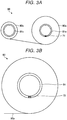
- FIGS. 3A and 3B are views illustrating an example of respective configurations of the ink ribbon unit 80 and the roll paper 90.
- FIG. 3A illustrates an example of the configuration of the ink ribbon unit 80
- FIG. 3B illustrates an example of the configuration of the roll paper 90.
- the ink ribbon unit 80 includes the unused ribbon 80a wound around a core 81a and a core 81c around which the used ribbon 80c is wound, and has a tag 71.
- the tag 71 is a Radio Frequency Identification (RFID) tag such as a label tag and communicates with an RFID reader/writer 113 (see FIG. 4 ).
- RFID Radio Frequency Identification
- the tag 71 is disposed inside of the first core 81a, in a layer at a boundary between the first core 81a and the unused ribbon 80a, in an edge area in which the first core 81a is exposed to the outside, or the like.
- the tag 71 is disposed in the first core 81a.
- the tag 71 may be disposed at another position in the ink ribbon unit 80, or disposed in the second core 81c.
- the roll paper 90 is formed by winding the label sheet 90a around a core 91 and has a tag 72.
- the tag 72 communicates with the RFID reader/writer 113.
- the tag 72 is disposed inside of the core 91.
- the tag 72 may be disposed in a place other than the above, for example, in the label sheet 90a on a base side of the core 91 which is not used for printing, or the like.
- Each of the tags 71 and 72 includes a Central Processing Unit (CPU) and a memory, and the tags, which can freely write and rewrite data in the memory, are used.
- each of the tags 71 and 72 includes an Integrated Circuit (IC) having the CPU and the memory, and an antenna.
- the antenna acquires power necessary for an operation of the IC by an electromagnetic induction action of a radio wave transmitted from an antenna of the RFID reader/writer 113, and further performs receiving of a command or data transmitted from the RFID reader/writer 113, and transmission of data to the RFID reader/writer 113.
- the CPU performs a process such as reading or writing for the memory in accordance with the command transmitted from the RFID reader/writer 113. For example, in a case of a write command, the CPU performs writing of the transmitted data in the memory. In addition, in a case of a read command, the CPU reads data from the memory and transmits the data to the RFID reader/writer 113.
- FIG. 4 is a block diagram illustrating an example of the hardware configuration of the label printer 1.
- the label printer 1 has a main control unit 100 (CPU 101, ROM 102, and RAM 103) that controls the entire label printer 1.
- the CPU 101 is a central processing unit and executes a control program of the ROM 102 to comprehensively control each unit of the hardware.
- the ROM 102 is a nonvolatile memory that stores various programs and various data. Various data include predetermined print setting information and the like.
- the RAM 103 is a volatile memory that is used as a work area by the CPU 101.
- the predetermined print setting information is a basic setting corresponding to a combination of the ink ribbon unit 80 and the roll paper 90, which is set in advance on the label printer 1 side.
- the setting includes various basic settings used for determining printing conditions such as setting of a print density and setting of a print speed.
- the main control unit 100 is connected to a USB controller 104, a communication Interface (I/F) 105, a display controller 106, an operation unit controller 107, a head driver 108, a motor driver 109, a motor driver 110, a motor driver 111, a motor driver 112, the RFID reader/writer 113, and the like via a bus 114.
- the main control unit 100 is connected to various sensors, the ribbon end sensor 65 (see FIG. 2 ), and the like on the carrying path.
- the USB controller 104 controls a USB memory to be connected.
- the print data or the like is stored in the USB memory.
- the communication I/F 105 is a communication interface such as a LAN and communicates with a host computer (not illustrated).
- the display controller 106 displays screen information on the display unit 11 based on an instruction from the main control unit 100.
- the operation unit controller 107 accepts an input operation from the operation unit 12 and outputs an input command or data to the main control unit 100.
- the head driver 108 controls the print head 41 to thermally transfer the ink of a print image to the label of the label sheet 90a.
- the adjustment of the print density is performed by controlling a temperature of a heating body by controlling a current value flowing through heating body of the print head 41 by the head driver 108.
- the motor driver 109, the motor driver 110, the motor driver 111, and the motor driver 112 respectively drive the platen motor 115, the carrying motor 116, the feed motor 117, and the winding motor 118.
- the platen motor 115 drives the platen 42 (see FIG. 2 ) to rotate.
- the carrying motor 116 drives the sheet carrying roller 31 (see FIG. 2 ) to rotate.
- the feed motor 117 and the winding motor 118 are motors for double-driving the ink ribbon unit 80, the feed motor 117 drives the ribbon holding shaft 61 (see FIG. 2 ) to rotate, and the winding motor 118 drives the ribbon take-up shaft 62 (see FIG. 2 ) to rotate.
- Each of the motors 115, 116, 117, and 118 is, for example, a stepping motor.
- the RFID reader/writer 113 communicates with the tag 71 and the tag 72 and reads data from the respective memories of the tag 71 and the tag 72 and writes data to the respective memories of the tag 71 and the tag 72.
- the antenna of the RFID reader/writer 113 is disposed in the label printer 1 so as to include each of the tag 71 and the tag 72 of the ink ribbon unit 80 and the roll paper 90 to be mounted in a communication range.
- main control unit 100 of the label printer 1 various functions are realized by executing a program of the ROM 102 by the CPU 101.
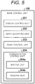
- FIG. 5 is a diagram illustrating an example of a function realized in the main control unit 100.
- a display control unit 201, an input accepting unit 202, a print control unit 203, and a communication control unit 204 are illustrated in FIG. 5 as an example of the function.
- the display control unit 201 outputs various kinds of screen information to the display controller 106.
- the input accepting unit 202 accepts a command or input data specified by an operation of the operation button 13 from the operation unit controller 107.
- the print control unit 203 executes an operation relating to printing, density adjustment, or the like which will be described later according to a program list of the ROM 102.
- the communication control unit 204 controls the RFID reader/writer 113. Specifically, the communication control unit 204 controls the RFID reader/writer 113 as a writing unit 204a and writes fine adjustment information which will be described later on the tag 71 (or the tag 72). In addition, the communication control unit 204 controls the RFID reader/writer 113 as a reading unit 204b and reads identification information and the fine adjustment information which will be described later from the tag 71 (or the tag 72).
- FIGS. 6A and 6B are diagrams illustrating an example of data stored in the tag 71 and the tag 72. Configurations of data stored in the tag 71 and the tag 72 are illustrated in FIGS. 6A and 6B respectively.
- FIG. 6A illustrates the configuration of the data stored in the tag 71
- FIG. 6B illustrates the configuration of the data stored in the tag 72.
- the tag 71 of the ink ribbon unit 80 stores identification information D1 and fine adjustment information D2 of the ink ribbon unit 80.
- the identification information D1 is identification information indicating a type of the ink ribbon unit 80 attached to the tag 71.
- the identification information D1 a code such as a model number is used.
- the identification information D1 may be stored in advance in the tag 71 before the ink ribbon unit 80 is shipped from the manufacturer.
- the label printer 1 acquires the identification information D1 from the ink ribbon unit 80 and stores it in the tag 71. In an embodiment, the former will be described.
- the fine adjustment information D2 is information obtained by combining identification information d1 (for example, the model number or the like) indicating the type of the roll paper 90 mounted in combination with the ink ribbon unit 80 with respect to the label printer 1, with a value (fine adjustment value) d2 indicating a positive or negative adjustment width of the print density finely adjusted by using a function of a setting mode by a user in a state where the ink ribbon unit 80 and the roll paper 90 are mounted.
- identification information d1 for example, the model number or the like
- fine adjustment value d2 indicating a positive or negative adjustment width of the print density finely adjusted by using a function of a setting mode by a user in a state where the ink ribbon unit 80 and the roll paper 90 are mounted.
- FIG. 6A illustrates an example of registration when a fine adjustment value is registered up to two types of the roll paper 90 in the fine adjustment information D2.
- a fine adjustment value "A1" is associated with one in which a type of the roll paper 90 is a "type 1”.
- a fine adjustment value "A2" is associated with one in which a type of the roll paper 90 is a "type 2". After that, when another roll paper 90 is mounted, information indicating a correspondence relationship between the roll paper 90 and the fine adjustment value is additionally registered.
- identification information D3 is identification information indicating the type of the roll paper 90 to which the tag 72 is attached. For example, as the identification information D3, a code such as the model number is stored. Timing to store the identification information D3 in the tag 72 is the same as that of the identification information D1.
- the label printer 1 when the label printer 1 is activated by inputting the power supply and initialization is performed, the label printer 1 acquires in advance each identification information of the ink ribbon unit 80 and the roll paper 90, and then displays an operation screen, and waits in an input waiting state.
- Each identification information about the ink ribbon unit 80 and the roll paper 90 is acquired from the communication control unit 204 by the print control unit 203.
- the communication control unit 204 causes the RFID reader/writer 113 to transmit each identification information from the tag 71 and the tag 72.
- the label printer 1 acquires each identification information from the ink ribbon unit 80 and the roll paper 90 after the change, displays the operation screen, and waits in the input waiting state.
- FIG. 7 is a flowchart illustrating an example of an operation of the label printer 1.
- the print control unit 203 instructs the display control unit 201 to display the operation screen and accepts an operation by the user from the input accepting unit 202 (Act 1).
- the print control unit 203 instructs the display control unit 201 to display setting items that can be set by the user, and accepts an operation by the user from the input accepting unit 202 (Act 3).
- the print control unit 203 instructs the display control unit 201 to display an adjustment screen of the print density, and accepts an operation by the user from the input accepting unit 202 (Act 5).
- the print control unit 203 accepts the number of times the up button and the down button are operated on the adjustment screen for finely adjusting a density value in predetermined steps, by one step, thereby converting the density value to an up width or a down width.
- the up width and the down width are adjustment widths (fine adjustment values) of positive and negative values, respectively.
- the print control unit 203 instructs the communication control unit 204 to register the fine adjustment value to the tag 71 (Act 7). Based on the instruction, the communication control unit 204 transmits to the tag 71 the fine adjustment information (identification information about the mounted roll paper 90 and fine adjustment value obtained in Act 5) and registers the fine adjustment information to the fine adjustment information D2 of the tag 71. After Act 7, the print control unit 203 proceeds to Act 1.
- the print control unit 203 when the print control unit 203 accepts an operation other than an item for adjusting the print density in the setting items (Act 4: No determination), the print control unit 203 performs a process corresponding to the accepting item (Act 8) and proceeds to Act 1.
- the print control unit 203 When the print control unit 203 does not accepts the operation of the registration button (Act 6: No determination) and accepts an operation of a return button (Act 9: Yes determination), the print control unit 203 proceeds to Act 1. If the print control unit 203 does not accept the operation of the return button (Act 9: No determination), the print control unit 203 waits until there is the operation of the registration button or the return button.
- the print control unit 203 When the print control unit 203 accepts the print operation (Act 10: Yes determination) instead of the operation of the setting mode (Act 2: No determination), the print control unit 203 performs the next printing.
- the print control unit 203 reads the print data of a destination specified by the user (Act 11). For example, when the print data of the USB memory is specified by the user, the print control unit 203 reads the print data from the USB memory.
- the print control unit 203 reads the predetermined print setting corresponding to the combination of the ink ribbon unit 80 and the roll paper 90 to be mounted, from the print setting information of the ROM 102 (Act 12).
- the print control unit 203 instructs the communication control unit 204 to acquire the fine adjustment information D2 from the tag 71 (Act 13).
- the communication control unit 204 causes the tag 71 transmit the fine adjustment information D2 and acquires the fine adjustment information D2.
- the print control unit 203 determines whether or not the identification information about the mounted roll paper 90 is registered in the acquired fine adjustment information D2 (Act 14).
- the print control unit 203 corrects the value of the print density of the predetermined print setting by the fine adjustment value associated with the identification information about the roll paper 90 in the fine adjustment information D2 (Act 15).
- the print control unit 203 determines printing conditions from the corrected print setting (Act 16) and performs printing under the printing conditions (Act 17).
- the print control unit 203 sets the value of the print density to an original value of the print setting, that is, to the predetermined print setting, determines the printing conditions from the predetermined print setting in Act 16, and performs printing under the predetermined printing conditions in Act 17.
- the print control unit 203 proceeds to Act 1.
- the print control unit 203 When the print control unit 203 accepts an end operation (Act 18: Yes determination) without accepting the print operation (Act 10: No determination), the print control unit 203 cause the power supply turn off by ending the process. When the print control unit 203 also does not accepts the ending operation (Act 18: No determination), the print control unit 203 proceeds to Act 2 and performs same determining process until there is any button operation.
- the identification information D1 and the identification information D3 of the ink ribbon unit 80 and the roll paper 90 are stored in the tags 71 and 72 in advance, respectively. If the identification information is not stored in the tags 71 and 72, when the ink ribbon unit 80 and the roll paper 90 are mounted on the label printer 1, the identification information D1 and D3 are written to the tags 71 and 72 by the RFID reader/writer 113.
- a catalogue list of the respective identification information is displayed on the display unit 11, and is selected by the user in the operation unit 12.
- Identification information printed on a product package may be manually input by the user in the operation unit 12, or a barcode printed on the product package may be input by barcode scan.
- Shapes and sizes of the ink ribbon unit 80 and the roll paper 90 which are mounted, and the like are detected by a sensor, and the identification information may be acquired from a corresponding list or the like.
- Acquired respective identification information is written by the communication control unit 204 by controlling the RFID reader/writer 113.
- the communication control unit 204 controls the RFID reader/writer 113 as the writing unit 204a, writes the identification information about the ink ribbon unit 80 in the tag 71, and writes the identification information about the roll paper 90 in the tag 72.
- the identification information D1 and the identification information D3 about the ink ribbon unit 80 and the roll paper 90 are stored in the tags 71 and 72, respectively, but if the label printer 1 can recognize the respective identification information about the ink ribbon unit 80 and the roll paper 90 which are mounted without communication with the tag 71 and the tag 72, the respective identification information may be excluded from the data configurations of the tag 71 and the tag 72. However, even in the case, the tag 71 and the tag 72 can be individually identified so that the label printer 1 can identify the tag 71 of the ink ribbon unit 80 and the tag 72 of the roll paper 90.
- the fine adjustment information D2 is stored in the tag 71 of the ink ribbon unit 80, but the configuration is not limited to the embodiments.
- the fine adjustment information D2 may be stored in the tag 72 of the roll paper 90 instead of the tag 71 of the ink ribbon unit 80.
- the fine adjustment information D2 may be stored in the tag 71 and the tag 72 of the ink ribbon unit 80 and the roll paper 90, respectively.
- thermal transfer type label printer an example of application to a thermal transfer type label printer is illustrated, but the embodiments are not limited to the thermal transfer type label printer.
- the example may be applied to an ink jet type, a heat sensitive type, or the like.
- the example is not limited to the label printer but may be applied to other printers.
- the label printer 1 of the aforementioned embodiments adjusts the print density from the predetermined print setting, the information indicating the combination of the ink ribbon unit 80 and the roll paper 90 which are mounted, and an adjustment value are stored in association with the tag 71 or the tag 72 of the ink ribbon unit 80 or the roll paper 90. Therefore, even when one or both of the ink ribbon unit 80 and the roll paper 90 is changed, if setting indicating the combination of the ink ribbon unit 80 and the roll paper 90 after the change is previously registered in the tag 71 or the tag 72, the adjustment value thereof can be read from the tag 71 or the tag 72, and setting of the print density can be automatically adjusted to adjusted setting. Therefore, it is possible to reduce a burden of the adjustment of the print setting including the print density by the user.
- the label printer 1 of the aforementioned embodiments is not limited to one in which the identification information is written in the tag 71 and the tag 72 as the ink ribbon unit 80 and the roll paper 90, and it is also possible to mount and use the tag 71 and the tag 72 in which the identification information is not written. Therefore, in the label printer 1 of the embodiments, if the tag 71 and the tag 72 are disposed in the ink ribbon unit 80 and the roll paper 90, it is possible to easily start using the function.
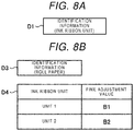
- FIGS. 8A and 8B are diagrams illustrating an example of data stored in the tag 71 and the tag 72 of Modification example 1.
- FIG. 8A illustrates a configuration of the data stored in the tag 71
- FIG. 8B illustrates a configuration of the data stored in the tag 72.
- a fine adjustment information D4 of FIG. 8B illustrates a configuration of data when the fine adjustment information is stored in the tag 72 of the roll paper 90.
- the fine adjustment information D4 includes identification information indicating a type of the ink ribbon unit 80 which is mounted in combination with the roll paper 90 with respect to a label printer 1, and information in association with a fine adjustment value which is finely adjusted by using a function of a setting mode by a user in a state where the ink ribbon unit 80 and the roll paper 90 are mounted.
- the fine adjustment information about the ink ribbon unit 80 of the new combination is registered here.
- FIG. 8B illustrates an example of registration when the fine adjustment value is registered up to two types of the ink ribbon units 80 in the fine adjustment information D4 as an example.
- a fine adjustment value "B1" is associated with the type of the ink ribbon unit 80 of "unit 1".
- a fine adjustment value "B2" is associated with the type of the ink ribbon unit 80 of "unit 2".
- an operation of the label printer 1 is such that a reading destination and a writing destination of the fine adjustment information D2 are changed from the tag 71 of the ink ribbon unit 80 to the tag 72 of the roll paper 90 in the operation (see FIG. 7 ) of the label printer 1 of the embodiments discussed above.
- a reading destination and a writing destination of the fine adjustment information D2 are changed from the tag 71 of the ink ribbon unit 80 to the tag 72 of the roll paper 90 in the operation (see FIG. 7 ) of the label printer 1 of the embodiments discussed above.
- FIGS. 9A and 9B are diagrams illustrating an example of data stored in the tag 71 and the tag 72 of Modification example 2.
- FIG. 9A illustrates a configuration of the data stored in the tag 71
- FIG. 9B illustrates a configuration of the data stored in the tag 72.
- FIG. 9A illustrates the same data configuration as that of FIG. 6A .
- FIG. 9B illustrates the same data configuration as that of FIG. 8B . That is, in Modification example 2, the fine adjustment information D2 and the fine adjustment information D4 are respectively stored in the tag 71 of the ink ribbon unit 80 and the tag 72 of the roll paper 90.
- fine adjustment values (A1, A2, ⁇ ) of the fine adjustment information D2 and fine adjustment values (B1, B2, ⁇ ) of the fine adjustment information D4 illustrated in FIGS. 9A and 9B the same value is used for the same combination of the ink ribbon unit 80 and the roll paper 90.
- an operation of the label printer 1 is such that the tag 72 of the roll paper 90 is added as a reading destination and a writing destination of the fine adjustment information D2 in the operation (see FIG. 7 ) of the label printer 1 of the embodiments discussed above. That is, when the fine adjustment information is read, the fine adjustment information D2 of the tag 71 and the fine adjustment information D4 of the tag 72 are read. When the fine adjustment information is written, it is written in the fine adjustment information D2 of the tag 71 and the fine adjustment information D4 of the tag 72.
- the other operation is substantially the same as the operation of the label printer 1 of the embodiments. Therefore, further explanation will be omitted here.
- Various programs used in the label printer of the embodiments are recorded and provided in computer-readable recording media such as a CD-ROM, a flexible disk (FD), a CD-R, a Digital Versatile Disk (DVD), and the like in installable format or executable format file, and may be read and executed by the ROM (flash ROM) of the label printer or the like.
- computer-readable recording media such as a CD-ROM, a flexible disk (FD), a CD-R, a Digital Versatile Disk (DVD), and the like in installable format or executable format file, and may be read and executed by the ROM (flash ROM) of the label printer or the like.
- the program may be stored on a computer connected to a network such as the Internet and may be provided by being downloaded via the network.
Landscapes
- Electronic Switches (AREA)
- Accessory Devices And Overall Control Thereof (AREA)
- Printers Characterized By Their Purpose (AREA)
Abstract
Description
- Embodiments described herein relate generally to a printer and a method carried out by a printer.
- A conventional label printer may have a function to automatically apply the same setting such as a print density associated with a certain combination of a print label and an ink ribbon. To achieve this function, the label printer via an IC chip reader communicates with two IC chips each disposed on the core of a strip label and the supply reel of an ink ribbon, and identifies the types of the label and the ink ribbon using the IDs assigned to them. Once these types have been identified, the label printer retrieves from a memory a setting predetermined for the combination of the label and the ink ribbon and applies the setting automatically.
- Such an automatic configuration about the print density is made for general use. Thus, a user may still need additional adjustments when he or she wants to print labels according to a specific printing policy, e.g., a company policy enforced by the company at which the user works. Moreover, the company user is often required to prepare labels with various combinations of labels and inks under the company policy, which may put heavy burden of re-adjustments to the default setting on the user.
- To solve the above-cited problems, there is provided a printer configured to connect with a detachable ink unit and a printing medium wound around a core, the printer comprising:
- a wireless tag reader and writer configured to communicate with a wireless tag;
- an input device configured to accept an input from a user; and
- a controller configured to control the wireless tag reader and writer to, when the input device accepts the input for adjusting a setting of the ink unit, store in at least one of a first tag included in the ink unit and a second tag included in the core, combination information indicating a combination of the ink unit and the printing medium that are attached to the printer and adjustment information indicating the setting.
- Preferably the controller may be configured to:
- control the wireless tag reader and writer to retrieve the stored combination information and the stored adjustment information; and
- carry out printing on the printing medium based on the retrieved combination information and the retrieved adjustment information.
- Preferably when the ink unit and the printing medium are attached to the printer for the first time, the controller may control the wireless tag reader and writer to store first identification information for the ink unit in the first tag and second identification information for the printing medium in the second tag.
- Preferably first identification information for the ink unit and second identification information for the printing medium may be each stored in the first and the second tag before the ink unit and the printing medium are attached to the printer.
- Preferably when the input device accepts the input for adjusting the setting, the controller may control the wireless tag reader and writer to store the combined information and the adjustment information that include the first and the second identification information each retrieved from the first and the second tag.
- Preferably the controller may be configured to store the adjustment information in both the first and the second tag.
- Preferably the adjustment information may indicate the setting for a print density.
- Preferably the setting may represent a positive or a negative adjustment value of the print density.
- Preferably the printing medium may be a label, and
- the printer may comprise a port configured to issue the label.
- In another exemplary embodiment, there is also provided a method carried out by a printer configured to connect with a detachable ink unit and a printing medium wound around a core, the method comprising:
- accepting an input to adjust a setting of the ink unit from a user; and
- storing in at least one of a first tag included in the ink unit and a second tag included in the core, combination information indicating a combination of the ink unit and the printing medium that are attached to the printer and adjustment information indicating the setting.
- Preferably the method may further comprise:
- retrieving the stored combination information and the stored adjustment information; and
- carrying out printing on the printing medium based on the retrieved combination information and the retrieved adjustment information.
- Preferably the method may further comprise:
when the ink unit and the printing medium are attached to the printer for the first time, storing first identification information for the ink unit in the first tag and second identification information for the printing medium in the second tag. - Preferably first identification information for the ink unit and second identification information for the printing medium are each stored in the first and the second tag before the ink unit and the printing medium are attached to the printer.
- Preferably the method may further comprise:
when the input for adjusting the setting is accepted, storing the combined information and the adjustment information that include the first and the second identification information each retrieved from the first and the second tag. - Preferably the adjustment information may be stored in both the first and the second tag.
- Preferably the adjustment information may indicate the setting for a print density.
- Preferably the setting may represent a positive or a negative adjustment value of the print density.
- Preferably the printing medium may a label, and
the printer may comprise a port configured to issue the label. - The above and other objects, features and advantages of the present invention will be made apparent from the following description of the preferred embodiments, given as non-limiting examples, with reference to the accompanying drawings, in which:
-
FIG. 1 is a view illustrating an example of an appearance configuration of a label printer of an embodiment. -
FIG. 2 is a view illustrating an example of a configuration of a printing mechanism accommodated in an inside of the label printer. -
FIGS. 3A and 3B are views illustrating an example of respective configurations of an ink ribbon unit and roll paper. -
FIG. 4 is a block diagram illustrating an example of a hardware configuration of the label printer. -
FIG. 5 is a diagram illustrating an example of a function realized in a main control unit. -
FIGS. 6A and 6B are diagrams illustrating an example of data stored in a first non-contact tag and a second non-contact tag. -
FIG. 7 is a flowchart illustrating an example of an operation of the label printer. -
FIGS. 8A and 8B are diagrams illustrating an example of data stored in a first non-contact tag and a second non-contact tag of Modification example 1. -
FIGS. 9A and 9B are diagrams illustrating an example of data stored in a first non-contact tag and a second non-contact tag of Modification example 2. - An embodiment provides a printer capable of reducing a burden of adjustment of print setting including a print density by a user.
- In general, according to one embodiment, a printer is configured to connect with a detachable ink unit and a printing medium wound around a core. The printer includes a wireless tag reader and writer configured to communicate with a wireless tag, an input device configured to accept an input from a user, and a controller. When the input device accepts the input for adjusting a setting of the ink unit, the controller controls the wireless tag reader and writer to store in at least one of a first tag included in the ink unit and a second tag included in the core, combination information indicating a combination of the ink unit and the printing medium that are attached to the printer and adjustment information indicating the setting.
- Hereinafter, an embodiment of a printer will be described in detail with reference to the drawings. An embodiment provides a thermal transfer type label printer. Here, an "ink unit" is also referred to as an "ink ribbon unit". The "ink unit" also includes parts that are detached together with ink. In addition, "roll paper" is illustrated as a "printing medium". The "printing medium" is, for example, a sheet of paper, a film, or the like for printing of print data (also including an image). The "printing medium" is not limited to a roll-like wound medium and may be a long sheet or the like.
-
FIG. 1 is a view illustrating an example of an appearance configuration of a label printer of an embodiment. Alabel printer 1 illustrated inFIG. 1 includes afront panel 10a in ahousing 10 and thefront panel 10a is provided with adisplay unit 11 and anoperation unit 12. Thedisplay unit 11 is a display device such as a liquid crystal display. Theoperation unit 12 includesoperation buttons 13 which are, for example, operation buttons for mode selection, operation buttons for instructing up, down, left, or right, and the like. Thelabel printer 1 includes a printing mechanism 20 (seeFIG. 2 ) on the inside thereof, and a label after printing is issued from alabel issuing port 14 provided in ahalf side 10b of thehousing 10. - The
label printer 1 has a structure in which theprinting mechanism 20 accommodated in thehousing 10 is exposed by lifting thehalf side 10b of thehousing 10 with twohinges 15 as fulcrums. An ink ribbon unit 80 (seeFIG. 2 ) and roll paper 90 (seeFIG. 2 ) which are set in theprinting mechanism 20 are detachable, and in thelabel printer 1 of an embodiment, the change can be made by lifting thehalf side 10b. - Various connectors such as a Universal Serial Bus (USB), a Local Area Network (LAN), and RS232C are disposed on a panel of a back surface of the
housing 10. -
FIG. 2 is a view illustrating an example of a configuration of theprinting mechanism 20 accommodated in the inside of thelabel printer 1. As illustrated inFIG. 2 , theprinting mechanism 20 includes asheet carrier 21, aprinting unit 22, asheet holder 23, an inkribbon supply device 24, aguide frame 25, and the like. - The
sheet carrier 21 includes asheet carrying roller 31, asupport unit 32, aleaf spring 33, and apinch roller 34. Thesheet carrying roller 31 is rotatably attached to aframe 35a and is rotated by power of a carrying motor 116 (seeFIG. 4 ). - The
support unit 32 is swingably attached to aframe 35b and supports thepinch roller 34 at one end. Thepinch roller 34 is rotatably attached to one end of thesupport unit 32. One end is attached to theframe 35b and the other end of theleaf spring 33 abuts against thepinch roller 34. However, thepinch roller 34 is urged by theleaf spring 33 and is pressed by thesheet carrying roller 31. - The
printing unit 22 includes aprint head 41 and aplaten 42. Theprint head 41 is fixed to ahead holder 44 rotatably attached to theguide frame 25. Theprint head 41 is a line type thermal printer head having a heating body. Theplaten 42 is rotatably attached to theframe 35a and is rotated by power of a platen motor 115 (seeFIG. 4 ). - A
label peeling plate 51 is provided as an optional label peeling module in the vicinity of thelabel issuing port 14. Thelabel peeling plate 51 bends alabel sheet 90a immediately before discharging from thelabel issuing port 14, peels a label from a backing sheet of thelabel sheet 90a, and discharges a peeled label from thelabel issuing port 14. The backing sheet from which the label is peeled off is wound around a winding shaft (not illustrated). Not only the label peeling module but also a cutter module or the like may be provided. - The
sheet holder 23 is a shaft for holding theroll paper 90. Theroll paper 90 is formed by winding the label sheet (label with the backing sheet) 90a around a core. Theroll paper 90 is rotatably held by the shaft which is thesheet holder 23 by being mounted through the core of theroll paper 90. Thelabel sheet 90a drawn out from the end portion of theroll paper 90 passes between thesheet carrying roller 31 and thepinch roller 34, and is sent toward aprinting unit 22 side by the rotation of thesheet carrying roller 31 and thepinch roller 34. In theprinting unit 22, thelabel sheet 90a passes between theplaten 42 and theprint head 41, and is fed to thelabel issuing port 14, and a label peeled off from thelabel sheet 90a is discharged to the outside of thehousing 10. - The ink
ribbon supply device 24 includes aribbon holding shaft 61 and a ribbon take-upshaft 62 which are driven by a double-drive system. Theribbon holding shaft 61 holds anunused ribbon 80a in theink ribbon unit 80 and is rotated by power of a feed motor 117 (seeFIG. 4 ). Anink ribbon 80b drawn out from theunused ribbon 80a is rotated around theguide frame 25 and is wound around the ribbon take-upshaft 62. The ribbon take-upshaft 62 is rotated by power of a winding motor 118 (seeFIG. 4 ) and recovers a usedribbon 80c from which the ink is peeled off after theprint head 41 transfers the ink to thelabel sheet 90a. - The
guide frame 25 is provided with aguide roller 64 that guides theink ribbon 80b drawn out from theribbon holding shaft 61. Theguide roller 64 is rotatably provided in theguide frame 25. After theink ribbon 80b is led to theguide roller 64, theink ribbon 80b passes through aribbon end sensor 65 which detects the end of theink ribbon 80b, and is led between theprint head 41 and theplaten 42. Theink ribbon 80b is heated by theprint head 41 between theprint head 41 and theplaten 42, and the ink of theink ribbon 80b is transferred to the label of thelabel sheet 90a. After the ink is peeled off, theink ribbon 80b is guided to the ribbon take-upshaft 62 side by aguide unit 66 of theguide frame 25 as the usedribbon 80c, and is wound around the ribbon take-upshaft 62. - Moreover, although not illustrated, in addition to the configuration, a sensor that detects a position of the
label sheet 90a or the like is disposed on a carrying path. - Subsequently, the
ink ribbon unit 80 and theroll paper 90 will be described. There are many combinations of theink ribbon unit 80 and theroll paper 90. For example, there are various options about the width of the rink ribbon, e.g., 60 mm, 90 mm, and 110 mm. There are also various options about a material of the label, e.g., "resin" and "semi-resin". Theroll paper 90 also has options including paper type labels, such as high quality paper, coated paper, and mirror coated paper, as well as synthetic paper type labels and film type labels. If they conform to the specifications of thelabel printer 1, theink ribbon unit 80 and theroll paper 90 can be set in theprinting mechanism 20 in any type of combination and used. -
FIGS. 3A and 3B are views illustrating an example of respective configurations of theink ribbon unit 80 and theroll paper 90.FIG. 3A illustrates an example of the configuration of theink ribbon unit 80 andFIG. 3B illustrates an example of the configuration of theroll paper 90. - As illustrated in
FIG. 3A , theink ribbon unit 80 includes theunused ribbon 80a wound around acore 81a and a core 81c around which the usedribbon 80c is wound, and has atag 71. - In an embodiment, the
tag 71 is a Radio Frequency Identification (RFID) tag such as a label tag and communicates with an RFID reader/writer 113 (seeFIG. 4 ). For example, thetag 71 is disposed inside of thefirst core 81a, in a layer at a boundary between thefirst core 81a and theunused ribbon 80a, in an edge area in which thefirst core 81a is exposed to the outside, or the like. In an embodiment, thetag 71 is disposed in thefirst core 81a. Alternatively, thetag 71 may be disposed at another position in theink ribbon unit 80, or disposed in thesecond core 81c. - As illustrated in
FIG. 3B , theroll paper 90 is formed by winding thelabel sheet 90a around acore 91 and has atag 72. - Similar to the
tag 71, thetag 72 communicates with the RFID reader/writer 113. For example, as illustrated inFIG. 3B , thetag 72 is disposed inside of thecore 91. Thetag 72 may be disposed in a place other than the above, for example, in thelabel sheet 90a on a base side of the core 91 which is not used for printing, or the like. - Each of the
tags tags writer 113, and further performs receiving of a command or data transmitted from the RFID reader/writer 113, and transmission of data to the RFID reader/writer 113. The CPU performs a process such as reading or writing for the memory in accordance with the command transmitted from the RFID reader/writer 113. For example, in a case of a write command, the CPU performs writing of the transmitted data in the memory. In addition, in a case of a read command, the CPU reads data from the memory and transmits the data to the RFID reader/writer 113. - Next, a hardware configuration of the
label printer 1 will be described.FIG. 4 is a block diagram illustrating an example of the hardware configuration of thelabel printer 1. As illustrated inFIG. 4 , thelabel printer 1 has a main control unit 100 (CPU 101,ROM 102, and RAM 103) that controls theentire label printer 1. - The
CPU 101 is a central processing unit and executes a control program of theROM 102 to comprehensively control each unit of the hardware. TheROM 102 is a nonvolatile memory that stores various programs and various data. Various data include predetermined print setting information and the like. TheRAM 103 is a volatile memory that is used as a work area by theCPU 101. - Here, the predetermined print setting information is a basic setting corresponding to a combination of the
ink ribbon unit 80 and theroll paper 90, which is set in advance on thelabel printer 1 side. The setting includes various basic settings used for determining printing conditions such as setting of a print density and setting of a print speed. - The
main control unit 100 is connected to aUSB controller 104, a communication Interface (I/F) 105, adisplay controller 106, anoperation unit controller 107, ahead driver 108, amotor driver 109, amotor driver 110, amotor driver 111, amotor driver 112, the RFID reader/writer 113, and the like via abus 114. In addition, although not illustrated, for example, themain control unit 100 is connected to various sensors, the ribbon end sensor 65 (seeFIG. 2 ), and the like on the carrying path. - The
USB controller 104 controls a USB memory to be connected. The print data or the like is stored in the USB memory. - The communication I/
F 105 is a communication interface such as a LAN and communicates with a host computer (not illustrated). - The
display controller 106 displays screen information on thedisplay unit 11 based on an instruction from themain control unit 100. Theoperation unit controller 107 accepts an input operation from theoperation unit 12 and outputs an input command or data to themain control unit 100. - The
head driver 108 controls theprint head 41 to thermally transfer the ink of a print image to the label of thelabel sheet 90a. The adjustment of the print density is performed by controlling a temperature of a heating body by controlling a current value flowing through heating body of theprint head 41 by thehead driver 108. - The
motor driver 109, themotor driver 110, themotor driver 111, and themotor driver 112 respectively drive theplaten motor 115, the carryingmotor 116, thefeed motor 117, and the windingmotor 118. - Specifically, the
platen motor 115 drives the platen 42 (seeFIG. 2 ) to rotate. The carryingmotor 116 drives the sheet carrying roller 31 (seeFIG. 2 ) to rotate. Thefeed motor 117 and the windingmotor 118 are motors for double-driving theink ribbon unit 80, thefeed motor 117 drives the ribbon holding shaft 61 (seeFIG. 2 ) to rotate, and the windingmotor 118 drives the ribbon take-up shaft 62 (seeFIG. 2 ) to rotate. Each of themotors - The RFID reader/
writer 113 communicates with thetag 71 and thetag 72 and reads data from the respective memories of thetag 71 and thetag 72 and writes data to the respective memories of thetag 71 and thetag 72. Moreover, the antenna of the RFID reader/writer 113 is disposed in thelabel printer 1 so as to include each of thetag 71 and thetag 72 of theink ribbon unit 80 and theroll paper 90 to be mounted in a communication range. - Next, a function of the
main control unit 100 of thelabel printer 1 will be described. In themain control unit 100, various functions are realized by executing a program of theROM 102 by theCPU 101. -
FIG. 5 is a diagram illustrating an example of a function realized in themain control unit 100. Adisplay control unit 201, aninput accepting unit 202, aprint control unit 203, and a communication control unit 204 are illustrated inFIG. 5 as an example of the function. - The
display control unit 201 outputs various kinds of screen information to thedisplay controller 106. Theinput accepting unit 202 accepts a command or input data specified by an operation of theoperation button 13 from theoperation unit controller 107. - The
print control unit 203 executes an operation relating to printing, density adjustment, or the like which will be described later according to a program list of theROM 102. - The communication control unit 204 controls the RFID reader/
writer 113. Specifically, the communication control unit 204 controls the RFID reader/writer 113 as awriting unit 204a and writes fine adjustment information which will be described later on the tag 71 (or the tag 72). In addition, the communication control unit 204 controls the RFID reader/writer 113 as a reading unit 204b and reads identification information and the fine adjustment information which will be described later from the tag 71 (or the tag 72). - Next, fine adjusting of the print setting using the
tag 71 and thetag 72 will be described. First, data stored in thetag 71 and thetag 72 will be described and then a processing flow of the fine adjusting will be described. -
FIGS. 6A and 6B are diagrams illustrating an example of data stored in thetag 71 and thetag 72. Configurations of data stored in thetag 71 and thetag 72 are illustrated inFIGS. 6A and 6B respectively.FIG. 6A illustrates the configuration of the data stored in thetag 71 andFIG. 6B illustrates the configuration of the data stored in thetag 72. - As illustrated in
FIG. 6A , thetag 71 of theink ribbon unit 80 stores identification information D1 and fine adjustment information D2 of theink ribbon unit 80. - In
FIG. 6A , the identification information D1 is identification information indicating a type of theink ribbon unit 80 attached to thetag 71. For example, as the identification information D1, a code such as a model number is used. For example, the identification information D1 may be stored in advance in thetag 71 before theink ribbon unit 80 is shipped from the manufacturer. Alternatively, when theink ribbon unit 80 is mounted on thelabel printer 1, thelabel printer 1 acquires the identification information D1 from theink ribbon unit 80 and stores it in thetag 71. In an embodiment, the former will be described. - The fine adjustment information D2 is information obtained by combining identification information d1 (for example, the model number or the like) indicating the type of the
roll paper 90 mounted in combination with theink ribbon unit 80 with respect to thelabel printer 1, with a value (fine adjustment value) d2 indicating a positive or negative adjustment width of the print density finely adjusted by using a function of a setting mode by a user in a state where theink ribbon unit 80 and theroll paper 90 are mounted. When a new combination of theroll paper 90 and theink ribbon unit 80 is mounted, fine adjustment information is registered for theroll paper 90 of the new combination by a process which will be described later. -
FIG. 6A illustrates an example of registration when a fine adjustment value is registered up to two types of theroll paper 90 in the fine adjustment information D2. A fine adjustment value "A1" is associated with one in which a type of theroll paper 90 is a "type 1". A fine adjustment value "A2" is associated with one in which a type of theroll paper 90 is a "type 2". After that, when anotherroll paper 90 is mounted, information indicating a correspondence relationship between theroll paper 90 and the fine adjustment value is additionally registered. - In
FIG. 6B , identification information D3 is identification information indicating the type of theroll paper 90 to which thetag 72 is attached. For example, as the identification information D3, a code such as the model number is stored. Timing to store the identification information D3 in thetag 72 is the same as that of the identification information D1. - In an embodiment, when the
label printer 1 is activated by inputting the power supply and initialization is performed, thelabel printer 1 acquires in advance each identification information of theink ribbon unit 80 and theroll paper 90, and then displays an operation screen, and waits in an input waiting state. Each identification information about theink ribbon unit 80 and theroll paper 90 is acquired from the communication control unit 204 by theprint control unit 203. The communication control unit 204 causes the RFID reader/writer 113 to transmit each identification information from thetag 71 and thetag 72. - When the
ink ribbon unit 80 or theroll paper 90 is changed after activation, thelabel printer 1 acquires each identification information from theink ribbon unit 80 and theroll paper 90 after the change, displays the operation screen, and waits in the input waiting state. - Hereinafter, on the premise that the
label printer 1 already acquires the identification information about theink ribbon unit 80 and theroll paper 90 to be mounted, an operation of thelabel printer 1 for adjusting thereafter will be described. -
FIG. 7 is a flowchart illustrating an example of an operation of thelabel printer 1. First, theprint control unit 203 instructs thedisplay control unit 201 to display the operation screen and accepts an operation by the user from the input accepting unit 202 (Act 1). - When the operation of the setting mode is accepted (Act 2: Yes determination), the
print control unit 203 instructs thedisplay control unit 201 to display setting items that can be set by the user, and accepts an operation by the user from the input accepting unit 202 (Act 3). - Subsequently, when an operation of an item for adjusting the print density in the setting items is accepted (Act 4: Yes determination), the
print control unit 203 instructs thedisplay control unit 201 to display an adjustment screen of the print density, and accepts an operation by the user from the input accepting unit 202 (Act 5). For example, theprint control unit 203 accepts the number of times the up button and the down button are operated on the adjustment screen for finely adjusting a density value in predetermined steps, by one step, thereby converting the density value to an up width or a down width. The up width and the down width are adjustment widths (fine adjustment values) of positive and negative values, respectively. - Subsequently, when the
print control unit 203 accepts an operation of a registration button (Act 6: Yes determination), theprint control unit 203 instructs the communication control unit 204 to register the fine adjustment value to the tag 71 (Act 7). Based on the instruction, the communication control unit 204 transmits to thetag 71 the fine adjustment information (identification information about the mountedroll paper 90 and fine adjustment value obtained in Act 5) and registers the fine adjustment information to the fine adjustment information D2 of thetag 71. After Act 7, theprint control unit 203 proceeds toAct 1. - Moreover, when the
print control unit 203 accepts an operation other than an item for adjusting the print density in the setting items (Act 4: No determination), theprint control unit 203 performs a process corresponding to the accepting item (Act 8) and proceeds toAct 1. - When the
print control unit 203 does not accepts the operation of the registration button (Act 6: No determination) and accepts an operation of a return button (Act 9: Yes determination), theprint control unit 203 proceeds toAct 1. If theprint control unit 203 does not accept the operation of the return button (Act 9: No determination), theprint control unit 203 waits until there is the operation of the registration button or the return button. - When the
print control unit 203 accepts the print operation (Act 10: Yes determination) instead of the operation of the setting mode (Act 2: No determination), theprint control unit 203 performs the next printing. - First, the
print control unit 203 reads the print data of a destination specified by the user (Act 11). For example, when the print data of the USB memory is specified by the user, theprint control unit 203 reads the print data from the USB memory. - Subsequently, the
print control unit 203 reads the predetermined print setting corresponding to the combination of theink ribbon unit 80 and theroll paper 90 to be mounted, from the print setting information of the ROM 102 (Act 12). - Subsequently, the
print control unit 203 instructs the communication control unit 204 to acquire the fine adjustment information D2 from the tag 71 (Act 13). The communication control unit 204 causes thetag 71 transmit the fine adjustment information D2 and acquires the fine adjustment information D2. - Subsequently, the
print control unit 203 determines whether or not the identification information about the mountedroll paper 90 is registered in the acquired fine adjustment information D2 (Act 14). - When the identification information is registered (Act 14: Yes determination), the
print control unit 203 corrects the value of the print density of the predetermined print setting by the fine adjustment value associated with the identification information about theroll paper 90 in the fine adjustment information D2 (Act 15). - Then, the
print control unit 203 determines printing conditions from the corrected print setting (Act 16) and performs printing under the printing conditions (Act 17). - On the other hand, when the identification information is not registered (Act 14: No determination), the
print control unit 203 sets the value of the print density to an original value of the print setting, that is, to the predetermined print setting, determines the printing conditions from the predetermined print setting in Act 16, and performs printing under the predetermined printing conditions in Act 17. - After printing, the
print control unit 203 proceeds toAct 1. - When the
print control unit 203 accepts an end operation (Act 18: Yes determination) without accepting the print operation (Act 10: No determination), theprint control unit 203 cause the power supply turn off by ending the process. When theprint control unit 203 also does not accepts the ending operation (Act 18: No determination), theprint control unit 203 proceeds toAct 2 and performs same determining process until there is any button operation. - In an embodiment, the identification information D1 and the identification information D3 of the
ink ribbon unit 80 and theroll paper 90 are stored in thetags tags ink ribbon unit 80 and theroll paper 90 are mounted on thelabel printer 1, the identification information D1 and D3 are written to thetags writer 113. - Specifically, for the respective identification information about the
ink ribbon unit 80 and theroll paper 90, for example, a catalogue list of the respective identification information is displayed on thedisplay unit 11, and is selected by the user in theoperation unit 12. Identification information printed on a product package may be manually input by the user in theoperation unit 12, or a barcode printed on the product package may be input by barcode scan. Shapes and sizes of theink ribbon unit 80 and theroll paper 90 which are mounted, and the like are detected by a sensor, and the identification information may be acquired from a corresponding list or the like. Acquired respective identification information is written by the communication control unit 204 by controlling the RFID reader/writer 113. Specifically, the communication control unit 204 controls the RFID reader/writer 113 as thewriting unit 204a, writes the identification information about theink ribbon unit 80 in thetag 71, and writes the identification information about theroll paper 90 in thetag 72. - In an embodiment, the identification information D1 and the identification information D3 about the
ink ribbon unit 80 and theroll paper 90 are stored in thetags label printer 1 can recognize the respective identification information about theink ribbon unit 80 and theroll paper 90 which are mounted without communication with thetag 71 and thetag 72, the respective identification information may be excluded from the data configurations of thetag 71 and thetag 72. However, even in the case, thetag 71 and thetag 72 can be individually identified so that thelabel printer 1 can identify thetag 71 of theink ribbon unit 80 and thetag 72 of theroll paper 90. - In the aforementioned embodiments, the fine adjustment information D2 is stored in the
tag 71 of theink ribbon unit 80, but the configuration is not limited to the embodiments. The fine adjustment information D2 may be stored in thetag 72 of theroll paper 90 instead of thetag 71 of theink ribbon unit 80. The fine adjustment information D2 may be stored in thetag 71 and thetag 72 of theink ribbon unit 80 and theroll paper 90, respectively. - In addition, in the above embodiments, an example of application to a thermal transfer type label printer is illustrated, but the embodiments are not limited to the thermal transfer type label printer. In addition, the example may be applied to an ink jet type, a heat sensitive type, or the like. The example is not limited to the label printer but may be applied to other printers.
- As described above, if the
label printer 1 of the aforementioned embodiments adjusts the print density from the predetermined print setting, the information indicating the combination of theink ribbon unit 80 and theroll paper 90 which are mounted, and an adjustment value are stored in association with thetag 71 or thetag 72 of theink ribbon unit 80 or theroll paper 90. Therefore, even when one or both of theink ribbon unit 80 and theroll paper 90 is changed, if setting indicating the combination of theink ribbon unit 80 and theroll paper 90 after the change is previously registered in thetag 71 or thetag 72, the adjustment value thereof can be read from thetag 71 or thetag 72, and setting of the print density can be automatically adjusted to adjusted setting. Therefore, it is possible to reduce a burden of the adjustment of the print setting including the print density by the user. - For example, in a company or the like, whenever the label is reattached, there is a scene in which the roll paper and the ink ribbon unit which are used for printing are changed for a corresponding combination, and printing is performed on the changed label. In this case, since the fine adjustment information about the print density previously adjusted by the combination is read out from the roll paper or the ink ribbon unit, whenever they are changed, the fine adjustment information about the previously adjusted print density of each combination is read out. Therefore, it is possible to save time and labor for re-adjusting the print density once previously adjusted, thereby reducing the burden on the user.
- The
label printer 1 of the aforementioned embodiments is not limited to one in which the identification information is written in thetag 71 and thetag 72 as theink ribbon unit 80 and theroll paper 90, and it is also possible to mount and use thetag 71 and thetag 72 in which the identification information is not written. Therefore, in thelabel printer 1 of the embodiments, if thetag 71 and thetag 72 are disposed in theink ribbon unit 80 and theroll paper 90, it is possible to easily start using the function. - In Modification example 1, a modification example of data stored in a
tag 71 and atag 72 is illustrated.FIGS. 8A and 8B are diagrams illustrating an example of data stored in thetag 71 and thetag 72 of Modification example 1.FIG. 8A illustrates a configuration of the data stored in thetag 71 andFIG. 8B illustrates a configuration of the data stored in thetag 72. - In Modification example 1, fine adjustment information is stored not in the
tag 71 of anink ribbon unit 80 but in thetag 72 of aroll paper 90. A fine adjustment information D4 ofFIG. 8B illustrates a configuration of data when the fine adjustment information is stored in thetag 72 of theroll paper 90. The fine adjustment information D4 includes identification information indicating a type of theink ribbon unit 80 which is mounted in combination with theroll paper 90 with respect to alabel printer 1, and information in association with a fine adjustment value which is finely adjusted by using a function of a setting mode by a user in a state where theink ribbon unit 80 and theroll paper 90 are mounted. When theroll paper 90 and theink ribbon unit 80 of a new combination are mounted, the fine adjustment information about theink ribbon unit 80 of the new combination is registered here. -
FIG. 8B illustrates an example of registration when the fine adjustment value is registered up to two types of theink ribbon units 80 in the fine adjustment information D4 as an example. A fine adjustment value "B1" is associated with the type of theink ribbon unit 80 of "unit 1". In addition, a fine adjustment value "B2" is associated with the type of theink ribbon unit 80 of "unit 2". After that, when anotherink ribbon unit 80 is mounted, information indicating a corresponding relationship between theink ribbon unit 80 and the fine adjustment value is additionally registered. - In Modification example 1, an operation of the
label printer 1 is such that a reading destination and a writing destination of the fine adjustment information D2 are changed from thetag 71 of theink ribbon unit 80 to thetag 72 of theroll paper 90 in the operation (seeFIG. 7 ) of thelabel printer 1 of the embodiments discussed above. Other than that, since it is substantially the same as the operation of thelabel printer 1 of the embodiments, further explanation will be omitted here. - In Modification example 2, another modification example of data stored in a
tag 71 and atag 72 is illustrated.FIGS. 9A and 9B are diagrams illustrating an example of data stored in thetag 71 and thetag 72 of Modification example 2.FIG. 9A illustrates a configuration of the data stored in thetag 71 andFIG. 9B illustrates a configuration of the data stored in thetag 72. -
FIG. 9A illustrates the same data configuration as that ofFIG. 6A . In addition,FIG. 9B illustrates the same data configuration as that ofFIG. 8B . That is, in Modification example 2, the fine adjustment information D2 and the fine adjustment information D4 are respectively stored in thetag 71 of theink ribbon unit 80 and thetag 72 of theroll paper 90. - Moreover, in fine adjustment values (A1, A2, ···) of the fine adjustment information D2 and fine adjustment values (B1, B2, ···) of the fine adjustment information D4 illustrated in
FIGS. 9A and 9B , the same value is used for the same combination of theink ribbon unit 80 and theroll paper 90. - In Modification example 2, an operation of the
label printer 1 is such that thetag 72 of theroll paper 90 is added as a reading destination and a writing destination of the fine adjustment information D2 in the operation (seeFIG. 7 ) of thelabel printer 1 of the embodiments discussed above. That is, when the fine adjustment information is read, the fine adjustment information D2 of thetag 71 and the fine adjustment information D4 of thetag 72 are read. When the fine adjustment information is written, it is written in the fine adjustment information D2 of thetag 71 and the fine adjustment information D4 of thetag 72. The other operation is substantially the same as the operation of thelabel printer 1 of the embodiments. Therefore, further explanation will be omitted here. - In Modification example 2, since the fine adjustment information is written in both the
tag 71 of theink ribbon unit 80 and thetag 72 of theroll paper 90, even when the fine adjustment information is not transmitted from both thetag 71 and thetag 72, it is possible to acquire the fine adjustment information. It is possible to use the label printer of Modification example 2 and the label printer illustrated in Modification example 1 together. In this case, it is possible to acquire the fine adjustment information by mounting theroll paper 90 used in the label printer illustrated in the embodiments discussed above or theink ribbon unit 80 used in the label printer illustrated in Modification example 1. - Various programs used in the label printer of the embodiments are recorded and provided in computer-readable recording media such as a CD-ROM, a flexible disk (FD), a CD-R, a Digital Versatile Disk (DVD), and the like in installable format or executable format file, and may be read and executed by the ROM (flash ROM) of the label printer or the like.
- The program may be stored on a computer connected to a network such as the Internet and may be provided by being downloaded via the network.
- While certain embodiments have been described, these embodiments have been presented by way of example only, and are not intended to limit the scope of the inventions. Indeed, the novel embodiments described herein may be embodied in a variety of other forms; furthermore, various omissions, substitutions and changes in the form of the embodiments described herein may be made without departing from the scope of the inventions. The accompanying claims and their equivalents are intended to cover such forms or modifications as would fall within the scope of the inventions.
Claims (15)
- A printer configured to connect with a detachable ink unit and a printing medium wound around a core, the printer comprising:a wireless tag reader and writer configured to communicate with a wireless tag;an input device configured to accept an input from a user; anda controller configured to control the wireless tag reader and writer to, when the input device accepts the input for adjusting a setting of the ink unit, store in at least one of a first tag included in the ink unit and a second tag included in the core, combination information indicating a combination of the ink unit and the printing medium that are attached to the printer and adjustment information indicating the setting.
- The printer according to claim 1, wherein the controller is configured to:control the wireless tag reader and writer to retrieve the stored combination information and the stored adjustment information; andcarry out printing on the printing medium based on the retrieved combination information and the retrieved adjustment information.
- The printer according to claim 1 or 2, wherein when the ink unit and the printing medium are attached to the printer for the first time, the controller controls the wireless tag reader and writer to store first identification information for the ink unit in the first tag and second identification information for the printing medium in the second tag.
- The printer according to claim 1 or 2, wherein first identification information for the ink unit and second identification information for the printing medium are each stored in the first and the second tag before the ink unit and the printing medium are attached to the printer.
- The printer according to claim 3 or 4, wherein when the input device accepts the input for adjusting the setting, the controller controls the wireless tag reader and writer to store the combined information and the adjustment information that include the first and the second identification information each retrieved from the first and the second tag.
- The printer according to any one of claims 1 to 5, wherein the controller is configured to store the adjustment information in both the first and the second tag.
- The printer according to any one of claims 1 to 6, wherein the adjustment information indicates the setting for a print density.
- The printer according to claim 7, wherein the setting represents a positive or a negative adjustment value of the print density.
- A method carried out by a printer configured to connect with a detachable ink unit and a printing medium wound around a core, the method comprising:accepting an input to adjust a setting of the ink unit from a user; andstoring in at least one of a first tag included in the ink unit and a second tag included in the core, combination information indicating a combination of the ink unit and the printing medium that are attached to the printer and adjustment information indicating the setting.
- The method according to claim 9, further comprising:retrieving the stored combination information and the stored adjustment information; andcarrying out printing on the printing medium based on the retrieved combination information and the retrieved adjustment information.
- The method according to claim 9 or 10, further comprising:when the ink unit and the printing medium are attached to the printer for the first time, storing first identification information for the ink unit in the first tag and second identification information for the printing medium in the second tag.
- The method according to claim 9 or 10, wherein first identification information for the ink unit and second identification information for the printing medium are each stored in the first and the second tag before the ink unit and the printing medium are attached to the printer.
- The method according to claim 11 or 12, further comprising:when the input for adjusting the setting is accepted, storing the combined information and the adjustment information that include the first and the second identification information each retrieved from the first and the second tag.
- The method according to any one of claims 9 to 13, wherein the adjustment information is stored in both the first and the second tag.
- The method according to any one of claims 9 to 14, wherein the adjustment information indicates the setting for a print density.
Applications Claiming Priority (1)
| Application Number | Priority Date | Filing Date | Title |
|---|---|---|---|
| JP2017172384A JP6909111B2 (en) | 2017-09-07 | 2017-09-07 | Printer |
Publications (2)
| Publication Number | Publication Date |
|---|---|
| EP3453535A1 true EP3453535A1 (en) | 2019-03-13 |
| EP3453535B1 EP3453535B1 (en) | 2020-03-11 |
Family
ID=63528641
Family Applications (1)
| Application Number | Title | Priority Date | Filing Date |
|---|---|---|---|
| EP18193262.5A Active EP3453535B1 (en) | 2017-09-07 | 2018-09-07 | Printer |
Country Status (4)
| Country | Link |
|---|---|
| US (1) | US20190070867A1 (en) |
| EP (1) | EP3453535B1 (en) |
| JP (1) | JP6909111B2 (en) |
| CN (1) | CN109466183B (en) |
Families Citing this family (9)
| Publication number | Priority date | Publication date | Assignee | Title |
|---|---|---|---|---|
| US20080117027A1 (en) * | 2006-11-16 | 2008-05-22 | Zih Corporation | Systems, methods, and associated rfid antennas for processing a plurality of transponders |
| US20220111672A1 (en) * | 2019-03-21 | 2022-04-14 | Hewlett-Packard Development Company, L.P. | Media identification |
| JP2021026537A (en) * | 2019-08-06 | 2021-02-22 | 東芝テック株式会社 | Wireless tag writing device, wireless tag writing method and program |
| JP7828878B2 (en) * | 2022-12-09 | 2026-03-12 | 東芝テック株式会社 | printing device |
| JP7849281B2 (en) * | 2022-12-09 | 2026-04-21 | 東芝テック株式会社 | printing device |
| CN116691187A (en) * | 2023-05-26 | 2023-09-05 | 武汉精臣智慧标识科技有限公司 | Label printer, printing method and storage medium |
| CN116728975B (en) * | 2023-07-13 | 2024-05-28 | 武汉精臣智慧标识科技有限公司 | Label printer and control method thereof |
| US12697829B2 (en) * | 2024-07-31 | 2026-08-04 | Brady Worldwide, Inc. | Printhead force adjust and lift system and method |
| US20260034818A1 (en) * | 2024-07-31 | 2026-02-05 | Brady Worldwide, Inc. | Ribbon cartridge automatic centering system and method |
Citations (2)
| Publication number | Priority date | Publication date | Assignee | Title |
|---|---|---|---|---|
| EP1462268A2 (en) * | 2003-03-28 | 2004-09-29 | Toshiba Tec Kabushiki Kaisha | Printer and consumables for use in printer |
| US20120014734A1 (en) * | 2010-07-15 | 2012-01-19 | Toshiba Tec Kabushiki Kaisha | Printer and roll |
Family Cites Families (10)
| Publication number | Priority date | Publication date | Assignee | Title |
|---|---|---|---|---|
| US6802659B2 (en) * | 1996-08-07 | 2004-10-12 | Mats Cremon | Arrangement for automatic setting of programmable devices and materials therefor |
| JP3782667B2 (en) * | 2001-02-08 | 2006-06-07 | 三菱重工業株式会社 | Color proofing method in printing |
| JP2008284807A (en) * | 2007-05-18 | 2008-11-27 | Toshiba Tec Corp | Thermal printer and program for controlling the same |
| JP2012045741A (en) * | 2010-08-25 | 2012-03-08 | Toshiba Tec Corp | Printer and roll |
| JP5774533B2 (en) * | 2012-03-29 | 2015-09-09 | 東芝テック株式会社 | Label printer |
| JP2014004803A (en) * | 2012-06-27 | 2014-01-16 | Sinfonia Technology Co Ltd | Printer |
| JP6171588B2 (en) * | 2013-06-05 | 2017-08-02 | コニカミノルタ株式会社 | Image forming apparatus |
| JP6252319B2 (en) * | 2014-04-02 | 2017-12-27 | コニカミノルタ株式会社 | Printing system, color adjustment chart creation method and creation control program |
| CN203974245U (en) * | 2014-06-20 | 2014-12-03 | 东芝泰格有限公司 | Rewrite printer |
| JP6516222B2 (en) * | 2015-06-29 | 2019-05-22 | シャープ株式会社 | Printing system |
-
2017
- 2017-09-07 JP JP2017172384A patent/JP6909111B2/en not_active Expired - Fee Related
-
2018
- 2018-08-21 US US16/108,035 patent/US20190070867A1/en not_active Abandoned
- 2018-08-27 CN CN201810982093.0A patent/CN109466183B/en not_active Expired - Fee Related
- 2018-09-07 EP EP18193262.5A patent/EP3453535B1/en active Active
Patent Citations (2)
| Publication number | Priority date | Publication date | Assignee | Title |
|---|---|---|---|---|
| EP1462268A2 (en) * | 2003-03-28 | 2004-09-29 | Toshiba Tec Kabushiki Kaisha | Printer and consumables for use in printer |
| US20120014734A1 (en) * | 2010-07-15 | 2012-01-19 | Toshiba Tec Kabushiki Kaisha | Printer and roll |
Also Published As
| Publication number | Publication date |
|---|---|
| JP6909111B2 (en) | 2021-07-28 |
| EP3453535B1 (en) | 2020-03-11 |
| JP2019048389A (en) | 2019-03-28 |
| CN109466183B (en) | 2020-10-27 |
| CN109466183A (en) | 2019-03-15 |
| US20190070867A1 (en) | 2019-03-07 |
Similar Documents
| Publication | Publication Date | Title |
|---|---|---|
| EP3453535B1 (en) | Printer | |
| RU2297333C2 (en) | Device for printing information on the consumable materials | |
| US9308760B2 (en) | Printer, printing method, and printing system | |
| US8366223B2 (en) | Apparatus for communicating with RFID tag | |
| US8830285B2 (en) | Printing apparatus and printing method | |
| CN101055627B (en) | RFID label, tag tape roll, RFID circuit element cartridge | |
| US20080190561A1 (en) | Apparatus and method for producing a sheet material | |
| JP7727263B2 (en) | Printing device, printing method, and printing program | |
| US7563044B2 (en) | Identifying compatible combination for a thermal printer | |
| US20220169045A1 (en) | Printer, control method of printer, and non-transitory computer-readable medium | |
| EP2723574B1 (en) | Print station | |
| CN101025793A (en) | Tag tape and tag label tape with print | |
| JP2026063260A (en) | Printing apparatus and printing method | |
| JP4593340B2 (en) | Label printer and control method of label printer | |
| JP2019101947A (en) | Electronic device, printing system, writing direction determination method, and program | |
| EP2022640B1 (en) | Printing apparatus | |
| JP4933234B2 (en) | Printing apparatus and printing method | |
| JP7396432B2 (en) | Printing device, control method, and program | |
| US20080219735A1 (en) | Printhead Assembly for a Credential Production Device | |
| JP4723103B2 (en) | Label printer | |
| JP7195939B2 (en) | Printer, printer control method, and program | |
| JP5212825B2 (en) | Print label production device | |
| JPH11277853A (en) | Portable printer | |
| JP2008284846A (en) | Thermal printer | |
| JP2005305936A (en) | Intermediate transfer type thermal transfer printer |
Legal Events
| Date | Code | Title | Description |
|---|---|---|---|
| PUAI | Public reference made under article 153(3) epc to a published international application that has entered the european phase |
Free format text: ORIGINAL CODE: 0009012 |
|
| STAA | Information on the status of an ep patent application or granted ep patent |
Free format text: STATUS: THE APPLICATION HAS BEEN PUBLISHED |
|
| AK | Designated contracting states |
Kind code of ref document: A1 Designated state(s): AL AT BE BG CH CY CZ DE DK EE ES FI FR GB GR HR HU IE IS IT LI LT LU LV MC MK MT NL NO PL PT RO RS SE SI SK SM TR |
|
| AX | Request for extension of the european patent |
Extension state: BA ME |
|
| STAA | Information on the status of an ep patent application or granted ep patent |
Free format text: STATUS: REQUEST FOR EXAMINATION WAS MADE |
|
| 17P | Request for examination filed |
Effective date: 20190712 |
|
| RBV | Designated contracting states (corrected) |
Designated state(s): AL AT BE BG CH CY CZ DE DK EE ES FI FR GB GR HR HU IE IS IT LI LT LU LV MC MK MT NL NO PL PT RO RS SE SI SK SM TR |
|
| RIC1 | Information provided on ipc code assigned before grant |
Ipc: B41J 3/407 20060101ALI20190802BHEP Ipc: B41J 17/32 20060101ALI20190802BHEP Ipc: B41J 15/04 20060101ALI20190802BHEP Ipc: B41J 2/32 20060101AFI20190802BHEP Ipc: B41J 29/38 20060101ALI20190802BHEP |
|
| GRAP | Despatch of communication of intention to grant a patent |
Free format text: ORIGINAL CODE: EPIDOSNIGR1 |
|
| STAA | Information on the status of an ep patent application or granted ep patent |
Free format text: STATUS: GRANT OF PATENT IS INTENDED |
|
| INTG | Intention to grant announced |
Effective date: 20190930 |
|
| GRAS | Grant fee paid |
Free format text: ORIGINAL CODE: EPIDOSNIGR3 |
|
| GRAA | (expected) grant |
Free format text: ORIGINAL CODE: 0009210 |
|
| STAA | Information on the status of an ep patent application or granted ep patent |
Free format text: STATUS: THE PATENT HAS BEEN GRANTED |
|
| AK | Designated contracting states |
Kind code of ref document: B1 Designated state(s): AL AT BE BG CH CY CZ DE DK EE ES FI FR GB GR HR HU IE IS IT LI LT LU LV MC MK MT NL NO PL PT RO RS SE SI SK SM TR |
|
| REG | Reference to a national code |
Ref country code: GB Ref legal event code: FG4D |
|
| REG | Reference to a national code |
Ref country code: CH Ref legal event code: EP |
|
| REG | Reference to a national code |
Ref country code: AT Ref legal event code: REF Ref document number: 1242656 Country of ref document: AT Kind code of ref document: T Effective date: 20200315 |
|
| REG | Reference to a national code |
Ref country code: IE Ref legal event code: FG4D |
|
| REG | Reference to a national code |
Ref country code: DE Ref legal event code: R096 Ref document number: 602018002993 Country of ref document: DE |
|
| PG25 | Lapsed in a contracting state [announced via postgrant information from national office to epo] |
Ref country code: FI Free format text: LAPSE BECAUSE OF FAILURE TO SUBMIT A TRANSLATION OF THE DESCRIPTION OR TO PAY THE FEE WITHIN THE PRESCRIBED TIME-LIMIT Effective date: 20200311 Ref country code: RS Free format text: LAPSE BECAUSE OF FAILURE TO SUBMIT A TRANSLATION OF THE DESCRIPTION OR TO PAY THE FEE WITHIN THE PRESCRIBED TIME-LIMIT Effective date: 20200311 Ref country code: NO Free format text: LAPSE BECAUSE OF FAILURE TO SUBMIT A TRANSLATION OF THE DESCRIPTION OR TO PAY THE FEE WITHIN THE PRESCRIBED TIME-LIMIT Effective date: 20200611 |
|
| REG | Reference to a national code |
Ref country code: NL Ref legal event code: MP Effective date: 20200311 |
|
| PG25 | Lapsed in a contracting state [announced via postgrant information from national office to epo] |
Ref country code: GR Free format text: LAPSE BECAUSE OF FAILURE TO SUBMIT A TRANSLATION OF THE DESCRIPTION OR TO PAY THE FEE WITHIN THE PRESCRIBED TIME-LIMIT Effective date: 20200612 Ref country code: BG Free format text: LAPSE BECAUSE OF FAILURE TO SUBMIT A TRANSLATION OF THE DESCRIPTION OR TO PAY THE FEE WITHIN THE PRESCRIBED TIME-LIMIT Effective date: 20200611 Ref country code: HR Free format text: LAPSE BECAUSE OF FAILURE TO SUBMIT A TRANSLATION OF THE DESCRIPTION OR TO PAY THE FEE WITHIN THE PRESCRIBED TIME-LIMIT Effective date: 20200311 Ref country code: SE Free format text: LAPSE BECAUSE OF FAILURE TO SUBMIT A TRANSLATION OF THE DESCRIPTION OR TO PAY THE FEE WITHIN THE PRESCRIBED TIME-LIMIT Effective date: 20200311 Ref country code: LV Free format text: LAPSE BECAUSE OF FAILURE TO SUBMIT A TRANSLATION OF THE DESCRIPTION OR TO PAY THE FEE WITHIN THE PRESCRIBED TIME-LIMIT Effective date: 20200311 |
|
| REG | Reference to a national code |
Ref country code: LT Ref legal event code: MG4D |
|
| PG25 | Lapsed in a contracting state [announced via postgrant information from national office to epo] |
Ref country code: NL Free format text: LAPSE BECAUSE OF FAILURE TO SUBMIT A TRANSLATION OF THE DESCRIPTION OR TO PAY THE FEE WITHIN THE PRESCRIBED TIME-LIMIT Effective date: 20200311 |
|
| PG25 | Lapsed in a contracting state [announced via postgrant information from national office to epo] |
Ref country code: PT Free format text: LAPSE BECAUSE OF FAILURE TO SUBMIT A TRANSLATION OF THE DESCRIPTION OR TO PAY THE FEE WITHIN THE PRESCRIBED TIME-LIMIT Effective date: 20200805 Ref country code: EE Free format text: LAPSE BECAUSE OF FAILURE TO SUBMIT A TRANSLATION OF THE DESCRIPTION OR TO PAY THE FEE WITHIN THE PRESCRIBED TIME-LIMIT Effective date: 20200311 Ref country code: SM Free format text: LAPSE BECAUSE OF FAILURE TO SUBMIT A TRANSLATION OF THE DESCRIPTION OR TO PAY THE FEE WITHIN THE PRESCRIBED TIME-LIMIT Effective date: 20200311 Ref country code: RO Free format text: LAPSE BECAUSE OF FAILURE TO SUBMIT A TRANSLATION OF THE DESCRIPTION OR TO PAY THE FEE WITHIN THE PRESCRIBED TIME-LIMIT Effective date: 20200311 Ref country code: SK Free format text: LAPSE BECAUSE OF FAILURE TO SUBMIT A TRANSLATION OF THE DESCRIPTION OR TO PAY THE FEE WITHIN THE PRESCRIBED TIME-LIMIT Effective date: 20200311 Ref country code: IS Free format text: LAPSE BECAUSE OF FAILURE TO SUBMIT A TRANSLATION OF THE DESCRIPTION OR TO PAY THE FEE WITHIN THE PRESCRIBED TIME-LIMIT Effective date: 20200711 Ref country code: CZ Free format text: LAPSE BECAUSE OF FAILURE TO SUBMIT A TRANSLATION OF THE DESCRIPTION OR TO PAY THE FEE WITHIN THE PRESCRIBED TIME-LIMIT Effective date: 20200311 Ref country code: LT Free format text: LAPSE BECAUSE OF FAILURE TO SUBMIT A TRANSLATION OF THE DESCRIPTION OR TO PAY THE FEE WITHIN THE PRESCRIBED TIME-LIMIT Effective date: 20200311 |
|
| REG | Reference to a national code |
Ref country code: AT Ref legal event code: MK05 Ref document number: 1242656 Country of ref document: AT Kind code of ref document: T Effective date: 20200311 |
|
| REG | Reference to a national code |
Ref country code: DE Ref legal event code: R097 Ref document number: 602018002993 Country of ref document: DE |
|
| PLBE | No opposition filed within time limit |
Free format text: ORIGINAL CODE: 0009261 |
|
| STAA | Information on the status of an ep patent application or granted ep patent |
Free format text: STATUS: NO OPPOSITION FILED WITHIN TIME LIMIT |
|
| PG25 | Lapsed in a contracting state [announced via postgrant information from national office to epo] |
Ref country code: DK Free format text: LAPSE BECAUSE OF FAILURE TO SUBMIT A TRANSLATION OF THE DESCRIPTION OR TO PAY THE FEE WITHIN THE PRESCRIBED TIME-LIMIT Effective date: 20200311 Ref country code: IT Free format text: LAPSE BECAUSE OF FAILURE TO SUBMIT A TRANSLATION OF THE DESCRIPTION OR TO PAY THE FEE WITHIN THE PRESCRIBED TIME-LIMIT Effective date: 20200311 Ref country code: AT Free format text: LAPSE BECAUSE OF FAILURE TO SUBMIT A TRANSLATION OF THE DESCRIPTION OR TO PAY THE FEE WITHIN THE PRESCRIBED TIME-LIMIT Effective date: 20200311 Ref country code: ES Free format text: LAPSE BECAUSE OF FAILURE TO SUBMIT A TRANSLATION OF THE DESCRIPTION OR TO PAY THE FEE WITHIN THE PRESCRIBED TIME-LIMIT Effective date: 20200311 |
|
| 26N | No opposition filed |
Effective date: 20201214 |
|
| PG25 | Lapsed in a contracting state [announced via postgrant information from national office to epo] |
Ref country code: PL Free format text: LAPSE BECAUSE OF FAILURE TO SUBMIT A TRANSLATION OF THE DESCRIPTION OR TO PAY THE FEE WITHIN THE PRESCRIBED TIME-LIMIT Effective date: 20200311 Ref country code: SI Free format text: LAPSE BECAUSE OF FAILURE TO SUBMIT A TRANSLATION OF THE DESCRIPTION OR TO PAY THE FEE WITHIN THE PRESCRIBED TIME-LIMIT Effective date: 20200311 |
|
| REG | Reference to a national code |
Ref country code: BE Ref legal event code: MM Effective date: 20200930 |
|
| PG25 | Lapsed in a contracting state [announced via postgrant information from national office to epo] |
Ref country code: LU Free format text: LAPSE BECAUSE OF NON-PAYMENT OF DUE FEES Effective date: 20200907 |
|
| PG25 | Lapsed in a contracting state [announced via postgrant information from national office to epo] |
Ref country code: IE Free format text: LAPSE BECAUSE OF NON-PAYMENT OF DUE FEES Effective date: 20200907 Ref country code: BE Free format text: LAPSE BECAUSE OF NON-PAYMENT OF DUE FEES Effective date: 20200930 |
|
| REG | Reference to a national code |
Ref country code: CH Ref legal event code: PL |
|
| PG25 | Lapsed in a contracting state [announced via postgrant information from national office to epo] |
Ref country code: TR Free format text: LAPSE BECAUSE OF FAILURE TO SUBMIT A TRANSLATION OF THE DESCRIPTION OR TO PAY THE FEE WITHIN THE PRESCRIBED TIME-LIMIT Effective date: 20200311 Ref country code: MT Free format text: LAPSE BECAUSE OF FAILURE TO SUBMIT A TRANSLATION OF THE DESCRIPTION OR TO PAY THE FEE WITHIN THE PRESCRIBED TIME-LIMIT Effective date: 20200311 Ref country code: CY Free format text: LAPSE BECAUSE OF FAILURE TO SUBMIT A TRANSLATION OF THE DESCRIPTION OR TO PAY THE FEE WITHIN THE PRESCRIBED TIME-LIMIT Effective date: 20200311 |
|
| PG25 | Lapsed in a contracting state [announced via postgrant information from national office to epo] |
Ref country code: MK Free format text: LAPSE BECAUSE OF FAILURE TO SUBMIT A TRANSLATION OF THE DESCRIPTION OR TO PAY THE FEE WITHIN THE PRESCRIBED TIME-LIMIT Effective date: 20200311 Ref country code: MC Free format text: LAPSE BECAUSE OF FAILURE TO SUBMIT A TRANSLATION OF THE DESCRIPTION OR TO PAY THE FEE WITHIN THE PRESCRIBED TIME-LIMIT Effective date: 20200311 Ref country code: AL Free format text: LAPSE BECAUSE OF FAILURE TO SUBMIT A TRANSLATION OF THE DESCRIPTION OR TO PAY THE FEE WITHIN THE PRESCRIBED TIME-LIMIT Effective date: 20200311 |
|
| PG25 | Lapsed in a contracting state [announced via postgrant information from national office to epo] |
Ref country code: LI Free format text: LAPSE BECAUSE OF NON-PAYMENT OF DUE FEES Effective date: 20210930 Ref country code: CH Free format text: LAPSE BECAUSE OF NON-PAYMENT OF DUE FEES Effective date: 20210930 |
|
| PGFP | Annual fee paid to national office [announced via postgrant information from national office to epo] |
Ref country code: GB Payment date: 20230720 Year of fee payment: 6 |
|
| PGFP | Annual fee paid to national office [announced via postgrant information from national office to epo] |
Ref country code: FR Payment date: 20230703 Year of fee payment: 6 Ref country code: DE Payment date: 20230712 Year of fee payment: 6 |
|
| REG | Reference to a national code |
Ref country code: DE Ref legal event code: R119 Ref document number: 602018002993 Country of ref document: DE |
|
| GBPC | Gb: european patent ceased through non-payment of renewal fee |
Effective date: 20240907 |
|
| PG25 | Lapsed in a contracting state [announced via postgrant information from national office to epo] |
Ref country code: DE Free format text: LAPSE BECAUSE OF NON-PAYMENT OF DUE FEES Effective date: 20250401 |
|
| PG25 | Lapsed in a contracting state [announced via postgrant information from national office to epo] |
Ref country code: GB Free format text: LAPSE BECAUSE OF NON-PAYMENT OF DUE FEES Effective date: 20240907 |
|
| PG25 | Lapsed in a contracting state [announced via postgrant information from national office to epo] |
Ref country code: FR Free format text: LAPSE BECAUSE OF NON-PAYMENT OF DUE FEES Effective date: 20240930 |