EP3453439A1 - Sterilization water discharge device and water treatment device including same - Google Patents
Sterilization water discharge device and water treatment device including same Download PDFInfo
- Publication number
- EP3453439A1 EP3453439A1 EP17792904.9A EP17792904A EP3453439A1 EP 3453439 A1 EP3453439 A1 EP 3453439A1 EP 17792904 A EP17792904 A EP 17792904A EP 3453439 A1 EP3453439 A1 EP 3453439A1
- Authority
- EP
- European Patent Office
- Prior art keywords
- water
- sterilization water
- sterilization
- discharge
- tray
- Prior art date
- Legal status (The legal status is an assumption and is not a legal conclusion. Google has not performed a legal analysis and makes no representation as to the accuracy of the status listed.)
- Granted
Links
Images



Classifications
-
- B—PERFORMING OPERATIONS; TRANSPORTING
- B01—PHYSICAL OR CHEMICAL PROCESSES OR APPARATUS IN GENERAL
- B01D—SEPARATION
- B01D35/00—Filtering devices having features not specifically covered by groups B01D24/00 - B01D33/00, or for applications not specifically covered by groups B01D24/00 - B01D33/00; Auxiliary devices for filtration; Filter housing constructions
- B01D35/18—Heating or cooling the filters
-
- B—PERFORMING OPERATIONS; TRANSPORTING
- B01—PHYSICAL OR CHEMICAL PROCESSES OR APPARATUS IN GENERAL
- B01D—SEPARATION
- B01D29/00—Filters with filtering elements stationary during filtration, e.g. pressure or suction filters, not covered by groups B01D24/00 - B01D27/00; Filtering elements therefor
- B01D29/88—Filters with filtering elements stationary during filtration, e.g. pressure or suction filters, not covered by groups B01D24/00 - B01D27/00; Filtering elements therefor having feed or discharge devices
- B01D29/92—Filters with filtering elements stationary during filtration, e.g. pressure or suction filters, not covered by groups B01D24/00 - B01D27/00; Filtering elements therefor having feed or discharge devices for discharging filtrate
-
- B—PERFORMING OPERATIONS; TRANSPORTING
- B01—PHYSICAL OR CHEMICAL PROCESSES OR APPARATUS IN GENERAL
- B01D—SEPARATION
- B01D35/00—Filtering devices having features not specifically covered by groups B01D24/00 - B01D33/00, or for applications not specifically covered by groups B01D24/00 - B01D33/00; Auxiliary devices for filtration; Filter housing constructions
- B01D35/02—Filters adapted for location in special places, e.g. pipe-lines, pumps, stop-cocks
- B01D35/04—Plug, tap, or cock filters filtering elements mounted in or on a faucet
-
- B—PERFORMING OPERATIONS; TRANSPORTING
- B01—PHYSICAL OR CHEMICAL PROCESSES OR APPARATUS IN GENERAL
- B01D—SEPARATION
- B01D35/00—Filtering devices having features not specifically covered by groups B01D24/00 - B01D33/00, or for applications not specifically covered by groups B01D24/00 - B01D33/00; Auxiliary devices for filtration; Filter housing constructions
- B01D35/14—Safety devices specially adapted for filtration; Devices for indicating clogging
-
- B—PERFORMING OPERATIONS; TRANSPORTING
- B01—PHYSICAL OR CHEMICAL PROCESSES OR APPARATUS IN GENERAL
- B01D—SEPARATION
- B01D35/00—Filtering devices having features not specifically covered by groups B01D24/00 - B01D33/00, or for applications not specifically covered by groups B01D24/00 - B01D33/00; Auxiliary devices for filtration; Filter housing constructions
- B01D35/14—Safety devices specially adapted for filtration; Devices for indicating clogging
- B01D35/147—Bypass or safety valves
-
- B—PERFORMING OPERATIONS; TRANSPORTING
- B01—PHYSICAL OR CHEMICAL PROCESSES OR APPARATUS IN GENERAL
- B01D—SEPARATION
- B01D35/00—Filtering devices having features not specifically covered by groups B01D24/00 - B01D33/00, or for applications not specifically covered by groups B01D24/00 - B01D33/00; Auxiliary devices for filtration; Filter housing constructions
- B01D35/14—Safety devices specially adapted for filtration; Devices for indicating clogging
- B01D35/157—Flow control valves: Damping or calibrated passages
-
- B—PERFORMING OPERATIONS; TRANSPORTING
- B01—PHYSICAL OR CHEMICAL PROCESSES OR APPARATUS IN GENERAL
- B01D—SEPARATION
- B01D35/00—Filtering devices having features not specifically covered by groups B01D24/00 - B01D33/00, or for applications not specifically covered by groups B01D24/00 - B01D33/00; Auxiliary devices for filtration; Filter housing constructions
- B01D35/14—Safety devices specially adapted for filtration; Devices for indicating clogging
- B01D35/157—Flow control valves: Damping or calibrated passages
- B01D35/1573—Flow control valves
-
- B—PERFORMING OPERATIONS; TRANSPORTING
- B01—PHYSICAL OR CHEMICAL PROCESSES OR APPARATUS IN GENERAL
- B01D—SEPARATION
- B01D35/00—Filtering devices having features not specifically covered by groups B01D24/00 - B01D33/00, or for applications not specifically covered by groups B01D24/00 - B01D33/00; Auxiliary devices for filtration; Filter housing constructions
- B01D35/16—Cleaning-out devices, e.g. for removing the cake from the filter casing or for evacuating the last remnants of liquid
-
- B—PERFORMING OPERATIONS; TRANSPORTING
- B01—PHYSICAL OR CHEMICAL PROCESSES OR APPARATUS IN GENERAL
- B01D—SEPARATION
- B01D61/00—Processes of separation using semi-permeable membranes, e.g. dialysis, osmosis or ultrafiltration; Apparatus, accessories or auxiliary operations specially adapted therefor
- B01D61/02—Reverse osmosis; Hyperfiltration ; Nanofiltration
-
- B—PERFORMING OPERATIONS; TRANSPORTING
- B01—PHYSICAL OR CHEMICAL PROCESSES OR APPARATUS IN GENERAL
- B01D—SEPARATION
- B01D61/00—Processes of separation using semi-permeable membranes, e.g. dialysis, osmosis or ultrafiltration; Apparatus, accessories or auxiliary operations specially adapted therefor
- B01D61/02—Reverse osmosis; Hyperfiltration ; Nanofiltration
- B01D61/025—Reverse osmosis; Hyperfiltration
-
- B—PERFORMING OPERATIONS; TRANSPORTING
- B01—PHYSICAL OR CHEMICAL PROCESSES OR APPARATUS IN GENERAL
- B01D—SEPARATION
- B01D61/00—Processes of separation using semi-permeable membranes, e.g. dialysis, osmosis or ultrafiltration; Apparatus, accessories or auxiliary operations specially adapted therefor
- B01D61/02—Reverse osmosis; Hyperfiltration ; Nanofiltration
- B01D61/08—Apparatus therefor
-
- B—PERFORMING OPERATIONS; TRANSPORTING
- B01—PHYSICAL OR CHEMICAL PROCESSES OR APPARATUS IN GENERAL
- B01D—SEPARATION
- B01D61/00—Processes of separation using semi-permeable membranes, e.g. dialysis, osmosis or ultrafiltration; Apparatus, accessories or auxiliary operations specially adapted therefor
- B01D61/02—Reverse osmosis; Hyperfiltration ; Nanofiltration
- B01D61/10—Accessories; Auxiliary operations
-
- B—PERFORMING OPERATIONS; TRANSPORTING
- B67—OPENING, CLOSING OR CLEANING BOTTLES, JARS OR SIMILAR CONTAINERS; LIQUID HANDLING
- B67D—DISPENSING, DELIVERING OR TRANSFERRING LIQUIDS, NOT OTHERWISE PROVIDED FOR
- B67D1/00—Apparatus or devices for dispensing beverages on draught
- B67D1/07—Cleaning beverage-dispensing apparatus
-
- C—CHEMISTRY; METALLURGY
- C02—TREATMENT OF WATER, WASTE WATER, SEWAGE, OR SLUDGE
- C02F—TREATMENT OF WATER, WASTE WATER, SEWAGE, OR SLUDGE
- C02F1/00—Treatment of water, waste water, or sewage
- C02F1/001—Processes for the treatment of water whereby the filtration technique is of importance
-
- C—CHEMISTRY; METALLURGY
- C02—TREATMENT OF WATER, WASTE WATER, SEWAGE, OR SLUDGE
- C02F—TREATMENT OF WATER, WASTE WATER, SEWAGE, OR SLUDGE
- C02F1/00—Treatment of water, waste water, or sewage
- C02F1/001—Processes for the treatment of water whereby the filtration technique is of importance
- C02F1/003—Processes for the treatment of water whereby the filtration technique is of importance using household-type filters for producing potable water, e.g. pitchers, bottles, faucet mounted devices
-
- C—CHEMISTRY; METALLURGY
- C02—TREATMENT OF WATER, WASTE WATER, SEWAGE, OR SLUDGE
- C02F—TREATMENT OF WATER, WASTE WATER, SEWAGE, OR SLUDGE
- C02F1/00—Treatment of water, waste water, or sewage
- C02F1/44—Treatment of water, waste water, or sewage by dialysis, osmosis or reverse osmosis
- C02F1/441—Treatment of water, waste water, or sewage by dialysis, osmosis or reverse osmosis by reverse osmosis
-
- B—PERFORMING OPERATIONS; TRANSPORTING
- B01—PHYSICAL OR CHEMICAL PROCESSES OR APPARATUS IN GENERAL
- B01D—SEPARATION
- B01D2201/00—Details relating to filtering apparatus
- B01D2201/16—Valves
- B01D2201/167—Single-way valves
-
- B—PERFORMING OPERATIONS; TRANSPORTING
- B01—PHYSICAL OR CHEMICAL PROCESSES OR APPARATUS IN GENERAL
- B01D—SEPARATION
- B01D2311/00—Details relating to membrane separation process operations and control
- B01D2311/26—Further operations combined with membrane separation processes
- B01D2311/2649—Filtration
-
- B—PERFORMING OPERATIONS; TRANSPORTING
- B01—PHYSICAL OR CHEMICAL PROCESSES OR APPARATUS IN GENERAL
- B01D—SEPARATION
- B01D2311/00—Details relating to membrane separation process operations and control
- B01D2311/26—Further operations combined with membrane separation processes
- B01D2311/2692—Sterilization
-
- B—PERFORMING OPERATIONS; TRANSPORTING
- B01—PHYSICAL OR CHEMICAL PROCESSES OR APPARATUS IN GENERAL
- B01D—SEPARATION
- B01D2313/00—Details relating to membrane modules or apparatus
- B01D2313/12—Specific discharge elements
-
- B—PERFORMING OPERATIONS; TRANSPORTING
- B01—PHYSICAL OR CHEMICAL PROCESSES OR APPARATUS IN GENERAL
- B01D—SEPARATION
- B01D2313/00—Details relating to membrane modules or apparatus
- B01D2313/18—Specific valves
-
- B—PERFORMING OPERATIONS; TRANSPORTING
- B01—PHYSICAL OR CHEMICAL PROCESSES OR APPARATUS IN GENERAL
- B01D—SEPARATION
- B01D2313/00—Details relating to membrane modules or apparatus
- B01D2313/22—Cooling or heating elements
-
- B—PERFORMING OPERATIONS; TRANSPORTING
- B01—PHYSICAL OR CHEMICAL PROCESSES OR APPARATUS IN GENERAL
- B01D—SEPARATION
- B01D2313/00—Details relating to membrane modules or apparatus
- B01D2313/50—Specific extra tanks
- B01D2313/501—Permeate storage tanks
-
- C—CHEMISTRY; METALLURGY
- C02—TREATMENT OF WATER, WASTE WATER, SEWAGE, OR SLUDGE
- C02F—TREATMENT OF WATER, WASTE WATER, SEWAGE, OR SLUDGE
- C02F1/00—Treatment of water, waste water, or sewage
- C02F1/46—Treatment of water, waste water, or sewage by electrochemical methods
-
- C—CHEMISTRY; METALLURGY
- C02—TREATMENT OF WATER, WASTE WATER, SEWAGE, OR SLUDGE
- C02F—TREATMENT OF WATER, WASTE WATER, SEWAGE, OR SLUDGE
- C02F2201/00—Apparatus for treatment of water, waste water or sewage
- C02F2201/002—Construction details of the apparatus
-
- C—CHEMISTRY; METALLURGY
- C02—TREATMENT OF WATER, WASTE WATER, SEWAGE, OR SLUDGE
- C02F—TREATMENT OF WATER, WASTE WATER, SEWAGE, OR SLUDGE
- C02F2303/00—Specific treatment goals
- C02F2303/04—Disinfection
-
- C—CHEMISTRY; METALLURGY
- C02—TREATMENT OF WATER, WASTE WATER, SEWAGE, OR SLUDGE
- C02F—TREATMENT OF WATER, WASTE WATER, SEWAGE, OR SLUDGE
- C02F2307/00—Location of water treatment or water treatment device
- C02F2307/06—Mounted on or being part of a faucet, shower handle or showerhead
-
- C—CHEMISTRY; METALLURGY
- C02—TREATMENT OF WATER, WASTE WATER, SEWAGE, OR SLUDGE
- C02F—TREATMENT OF WATER, WASTE WATER, SEWAGE, OR SLUDGE
- C02F2307/00—Location of water treatment or water treatment device
- C02F2307/10—Location of water treatment or water treatment device as part of a potable water dispenser, e.g. for use in homes or offices
Definitions
- the present disclosure relates to a sterilization water discharge device configured to receive sterilization water discharged from a discharge member, through which water is discharged, and to discharge the received sterilization water externally, and a water treatment device including the same.
- Water treatment devices are devices processing water to supply the processed water to users.
- a water purifier for supplying water to a user by filtering the water, an ionizer for electrolyzing the water into alkaline water or acid water to supply the water to a user, a carbonated water generator for dissolving carbonic acid in water to supply the water to a user, and the like.
- a storage tank in which water is stored, a tube through which water flows, or the like may be contaminated by foreign substances, bacteria or the like.
- the water treated in the water treatment device may also be contaminated such that contaminated water may be supplied to a user.
- sterilization water is produced in the related art water treatment device to sterilize the water treatment device periodically or when necessary.
- sterilization water having sterilized the water treatment device, is discharged through a discharge member that discharges treated-water processed by the water treatment device.
- a separate drainage container is installed in the discharge member, so that sterilization water discharged from the discharge member may be provided to the drainage container. After the drainage container having the sterilization water therein is separated from the discharge member, the sterilization water stored in the drainage container is discarded.
- An aspect of the present disclosure is to provide a sterilization water discharge device and a water treatment device by recognizing at least one of the above-mentioned requirements or problems in the related art.
- sterilization water having sterilized a water treatment device, may be smoothly drained.
- the drainage of sterilization water having sterilized a water treatment device may be facilitated.
- a sterilization water discharge device and a water treatment device including the same may be characterized as described below.
- a sterilization water discharge device includes a tray part movably provided below a discharge member through which water is discharged, and configured to receive sterilization water discharged from the discharge member to drain the sterilization water; and a movement driving part configured to move the tray part.
- the tray part may move between a standby position, in which water other than the sterilization water, discharged from the discharge member, is not provided to the tray part, and a sterilization water drainage position, in which the sterilization water, discharged from the discharge member is provided to the tray part.
- the tray part may be provided with a sterilization water receiving portion formed therein, the sterilization water receiving portion having an open upper portion through which the sterilization water discharged from the discharge member is provided, and may be provided with a drainage port connected to the sterilization water receiving portion to drain the sterilization water contained in the sterilization water receiving portion.
- a bottom of the sterilization water receiving portion may be inclined toward the drainage port.
- the sterilization water discharge device may further include a movement guide part positioned below the discharge member and configured to allow the tray part to be movable.
- the movement guide part may include a water passage through which water other than sterilization water, discharged from the discharge member, passes and falls, in the standby position of the tray part, and a tray passage through which the tray part passes to move between the standby position and the sterilization water drainage position below the water passage.
- the movement guide part may further include a drainage port movement passage through which the drainage port passes and in which the drainage port is positioned and moves by movement of the tray part.
- the tray part may include a tray member that is provided with the sterilization water receiving portion and the drainage port; and a moving member in which an insertion portion is provided, into which the tray member is provided, the moving member being movably provided in the movement guide part.
- the moving member may be provided with a guide protrusion
- the movement guide part may be provided with a guide groove formed therein into which the guide protrusion is inserted and through which the guide protrusion moves.
- the movement guide part may be provided with a position sensor, sensing whether the tray part has moved to the sterilization water drainage position from the standby position.
- the movement guide part may be provided with a stopper member that prevents the tray part from moving further in a direction opposite to a direction of the sterilization water drainage position from the standby position.
- the sterilization water discharge device may further include a drain tank configured to receive sterilization water drained from the drainage port and to be connected to a sterilization water drain line to drain the sterilization water.
- the drain tank may be provided with a sterilization water receiving portion having an open upper portion through which the sterilization water drained from the drainage port is provided, and may be provided with a drain connection port connected to the sterilization water receiving portion and the sterilization water drain line.
- the sterilization water drain line may be provided with a drain pump.
- the drain tank may be provided with a water level sensor sensing a level of the sterilization water contained in the sterilization water receiving portion.
- the movement driving part may include a driving motor; and a gear connected to the driving motor and engaged with a gear portion disposed on the tray part.
- a water treatment device includes a filtration part including a water filter to filter water supplied from a water supply source; a storage part storing the water filtered by the filtration part; a discharge part including a discharge member externally discharging the water stored in the storage part; a sterilizing part producing sterilization water, using water filtered by at least one water filter in the water filter, to sterilize the storage part and the discharge part with sterilization water; and the sterilization water discharge device.
- the discharge member is directly connected to the storage part by a discharge line.
- a tray part may be movably provided below a discharge member from which water is discharged, to receive sterilization water discharged from the discharge member to drain the sterilization water.
- the drainage of sterilization water, having sterilized a water treatment device may be easily performed.
- sterilization water having sterilized a water treatment device, may be smoothly drained.
- FIGS. 1 to 6 a sterilization water discharge device according to an exemplary embodiment will be described with reference to FIGS. 1 to 6 .
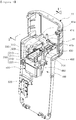
- FIG. 1 is a perspective view of a sterilization water discharge device according to an exemplary embodiment
- FIG. 2 is a perspective view of a sterilization water discharge device according to an exemplary embodiment, when viewed in a direction different from that illustrated in FIG. 1 .
- FIG. 3 is an exploded perspective view of FIG. 1
- FIG. 4 is a cross-sectional view taken along line I-I' of FIG. 1 .
- FIGS. 5 and 6 are cross-sectional views illustrating operations of the sterilization water discharge device as illustrated in FIG. 4 , according to an exemplary embodiment.
- a sterilization water discharge device 100 may include a tray part 200 and a movement driving part 300, as illustrated in FIGS. 1 , 3 and 4 .
- the tray part 200 may be movably provided below a discharge member 41.
- Water having been processed by a water treatment device to be described below, such as a water purifier including the discharge member 41 or the like, may be discharged from the discharge member 41.
- a water purifier including the discharge member 41 or the like
- purified water or purified cold water filtered by water filters 21, 22 and 23 to be described later, included in the water treatment device 10 may be discharged from the discharge member 41.
- sterilization water for example, water having been produced in the water treatment device 10 and having sterilized the water treatment device 10, may be discharged from the discharge member 41.
- the discharge member 41 may be, for example, a cock or a faucet, but is not particularly limited, and any known discharge member may be used as long as water and sterilization water can be discharged therethrough.
- the discharge member 41 may include a purified water connection port 41a connected to a purified water tank 31 included in the water treatment device 10, a cold water connection port 41b connected to a cold water tank 32, and a hot water connection port 41c connected to an instantaneous water heater 33, for example, as illustrated in FIGS. 1 and 3 .
- the discharge member 41 may be provided with a purified cold water outlet 41d connected to the purified water connection port 41a and the cold water connection port 41b, and a hot water outlet 41e connected to the hot water connection port 41c.
- purified water stored in the purified water tank 31 of the water treatment device 10 to be described later may be discharged through the purified water connection port 41a and the purified cold water outlet 41d of the discharge member 41.
- cold water stored in the cold water tank 32 of the water treatment device 10 to be described later may be discharged through the cold water connection port 41b and the purified cold water outlet 41d of the discharge member 41.
- Hot water produced by the instantaneous water heater 33 of the water treatment device 10 to be described later may be discharged through the hot water connection port 41c and the hot water outlet 41e of the discharge member 41.
- sterilization water having been produced by the water treatment device 10 and having sterilized the water treatment device 10, may be discharged through the purified water connection port 41a and the purified cold water outlet 41d, or the cold water connection port 41b and the purified cold water outlet 41d of the discharge member 41.
- the configuration and the number of the discharge members 41 are not particularly limited, and any configuration and number of discharge members 41 may be employed, as long as water other than sterilization water, such as purified water, cold water, hot water or the like, and sterilization water, as described above, may be discharged thereby.
- the tray part 200 may be configured to receive sterilization water discharged from the discharge member 41 and to drain the received sterilization water.
- the tray part 200 may be movable between a standby position as illustrated in FIG. 5 and a sterilization water drainage position as illustrated in FIG. 6 .
- the tray part 200 may not receive water other than sterilization water, discharged from the discharge member 41.
- sterilization water For example, purified water, cold water or hot water may not be provided to the tray part in the standby position.
- the tray part 200 may receive sterilization water discharged from the discharge member 41.
- sterilization water discharged from the discharge member 41 may be drained by only moving the tray part 200 according to an exemplary embodiment in the present disclosure.
- sterilization water having sterilized the water treatment device 10 may be easily performed.
- sterilization water having sterilized the water treatment device 10 may be smoothly drained.
- the tray part 200 may be provided with a sterilization water receiving portion 211 formed therein, having an open upper portion.
- a sterilization water receiving portion 211 formed therein, having an open upper portion.
- the tray part 200 may include a drainage port 212.
- the drainage port 212 may be connected to the sterilization water receiving portion 211.
- the sterilization water discharged from the discharge member 41 to be provided to the sterilization water receiving portion 211 may be drained through the drainage port 212.
- the bottom of the sterilization water receiving portion 211 may be inclined toward the drainage port 212 as illustrated in FIG. 4 .
- the sterilization water discharged from the discharge member 41 and provided to the sterilization water receiving portion 211 may easily flow into the drainage port 212 from the interior of the sterilization water receiving portion 211.
- the tray part 200 may be provided with a gear portion 213 formed thereon.
- the tray part 200 may be formed with the gear portion 213 that is a rack gear in a length direction.
- a gear 320 to be described later, included in the movement driving part 300, may be engaged with the gear portion 213.
- the gear 320 may be, for example, a pinion gear.
- the tray part 200 may be moved between the standby position and the sterilization water drainage position, by rotation of the gear 320 by a driving motor 310 to be described later, included in the movement driving part 300 and connected to the gear 320, as illustrated in FIGS. 5 and 6 .
- the tray part 200 may be provided with a magnet 214 as illustrated in FIG. 3 .
- a position sensor 450 included in a movement guide part 400 to be described later may sense the magnet 214, to sense that the tray part 200 has moved to the sterilization water drainage position.
- the tray part 200 may include a tray member 210 and a moving member 220.
- the tray member 210 may be provided with the sterilization water receiving portion 211 formed therein, and may be provided with the drainage port 212.
- the tray member 210 may be provided with the gear portion 213 described above and the magnet 214.
- the moving member 220 may be provided with an insertion portion 221 formed therein, into which the tray member 210 may be inserted, as illustrated in FIGS. 3 and 4 .
- the tray member 210 may be combined with the moving member 220, in a state being inserted into the insertion portion 221 of the moving member 220.
- the moving member 220 may be movably provided in the movement guide part 400. Thus, as the moving member 220 moves in the movement guide part 400, the tray member 210 may also be moved.
- the moving member 220 may be provided with a guide protrusion 222 formed thereon.
- the guide protrusion 222 may be movably inserted into a guide groove 440 to be described later, formed in the movement guide part 400, and thus, the moving member 220 may be moved in the movement guide part 400.
- the configuration in which the moving member 220 is movably provided in the movement guide part 400 is not particularly limited, and any configuration known in the art may be applied thereto.
- the configuration of the tray part 200 is not particularly limited, and any known configuration may be employed as long as the tray part 200 is configured to be movable below the discharge member 41 and to receive sterilization water discharged from the discharge member 41 to discharge the received sterilization water.
- the movement driving part 300 may be configured to move the tray part 200.
- the movement driving part 300 may include the driving motor 310 and the gear 320 meshing with the gear portion 213, the gear portion 213 being disposed in the tray part 200, for example, provided with the tray member 210 of the tray part 200.
- the gear portion 213 of the tray part 200 may be, for example, a rack gear as described above, and the gear 320 may be, for example, a pinion gear.
- the tray part 200 may be moved by the rotation of the gear 320 as the driving motor 310 is driven.
- the configuration of the movement driving part 300 is not particularly limited, and any known configuration may be used as long as the configuration allows the tray part 200 to move.
- the sterilization water drainage device 100 may further include the movement guide part 400 as illustrated in FIGS. 1 to 4 .
- the movement guide part 400 may be positioned below the discharge member 41 as illustrated in FIGS. 1 , 2 and 4 .
- the movement guide part 400 may be installed in a guide-part installation portion 11a formed in a device body 11 included in the water treatment device 10 such as a water purifier or the like, thereby being located below the discharge member 41.
- the configuration in which the movement guide part 400 is positioned below the discharge member 41 is not particularly limited, and any known configuration may be applied thereto.
- the movement guide part 400 may be provided with the tray part 200 provided movably.
- the movement guide part 400 may include a water passage 410 and a tray passage 420.
- the tray part 200 may pass through the tray passage 420 to move between the standby position and the sterilization water drainage position below the water passage 410.
- the water passage 410 may be horizontally formed in the movement guide part 400, and the tray passage 420 may be vertically formed in the movement guide part 400.
- the water passage 410 and the tray passage 420 may be connected to each other.
- the configuration and shape of the water passage 410 and the tray passage 420 are not particularly limited, and any configuration and shape may be used.
- the movement guide part 400 may further include a drainage port movement passage 430. As illustrated in FIG. 4 , the drainage port 212 of the tray part 200 may pass through the drainage port movement passage 430. As the tray part 200 moves, the drainage port 212 may be moved in the drainage port movement passage 430.
- the movement of the tray part 200 may be prevented from being disturbed by the drainage port 212.
- the guide groove 440 may be formed in the movement guide part 400 .
- the guide protrusion 222 of the tray part 200 described above may be movably inserted into the guide groove 440.
- the guide groove 440 may be lengthwise respectively formed in portions of both sides of the movement guide part 400 provided on the drainage port movement passage 430 in a length direction of the movement guide part 400.
- the tray part 200 may be moved in the movement guide part 400.
- the configuration in which the tray part 200 is movably provided in the movement guide part 400 is not particularly limited, and any known configuration may be used.
- a position sensor 450 may be provided to sense whether the tray part 200 has moved from the standby position to the sterilization water drainage position.
- the position sensor 450 may be disposed in a portion of the movement guide part 400 to correspond to a position of the sterilization water drainage position of the tray part 200.
- the position sensor 450 may sense the magnet 214 provided in the tray part 200.
- the position sensor 450 may sense the magnet 214 of the tray part 200, to detect that the tray part 200 has moved to the sterilization water drainage position.
- sterilization water may be discharged from the discharge member 41 as illustrated in FIG. 6 .
- the sterilization water discharged from the discharge member 41 may be provided to the tray part 200 to be drained.
- the configuration in which the position sensor 450 senses that the tray part 200 has moved to the sterilization water drainage position is not particularly limited, and any known configuration may be employed.
- the movement guide part 400 may be provided with a stopper member 460.
- the stopper member 460 may prevent the tray part 200 from moving further in a direction opposite to that of the sterilization water drainage position, from the standby position.
- the stopper member 460 may be provided on a portion of the movement guide part 400, corresponding to the standby position of the tray part 200, and may have the form of a ' ⁇ '. Thus, after the tray part 200 is moved to the standby position by the movement driving part 300, the stopper member 460 may prevent the tray part 200 from moving further in the direction opposite to that of the sterilization water drainage position.
- the position and the shape of the stopper member 460 are not particularly limited, and any position and shape may be used as long as the tray part 200 may be prevented from moving in a direction opposite to that of the sterilization water drainage position from the standby position, in the position and shape.
- the sterilization water discharge device 100 may further include a drain tank 500.
- the drain tank 500 may contain sterilization water drained from the drainage port 212 of the tray part 200. Then, the drain tank 500 may be connected to a sterilization water drain line LSD as illustrated in FIG. 7 , such that sterilization water may be drained.
- the drain tank 500 may be located below the drainage port 212 of the tray part 200.
- a sterilization water receiving portion 510 may be formed in the drain tank 500, and the sterilization water receiving portion 510 may have an open upper portion through which sterilization water, drained from the drainage port 212, may be provided to the sterilization water receiving portion 510.
- the drain tank 500 may be provided with a drain connection port 520 connected to the sterilization water receiving portion 510 and the sterilization water drain line LSD.
- sterilization water discharged from the discharge member 41 and provided to the tray part 200, in the sterilization water drainage position of the tray part 200, may be discharged to the drain tank 500 through the drainage port 212, and may be provided to the sterilization water receiving portion 510 through the open upper portion of the sterilization water receiving portion 510.
- the sterilization water provided to the sterilization water receiving portion 510 of the drain tank 500 may be introduced into the sterilization water drain line LSD through the drain connection port 520, to be drained.
- the sterilization water drain line LSD may be provided with a drain pump PDL.
- the sterilization water provided to the sterilization water receiving portion 510 of the drain tank 500 may be easily introduced into the sterilization water drain line LSD through the drain connection port 520 to be drained, by driving the drain pump PDL.
- the drain tank 500 may be provided with a water level sensor (not shown) to sense the level of sterilization water provided to the sterilization water receiving portion 510.
- a water level sensor (not shown) to sense the level of sterilization water provided to the sterilization water receiving portion 510.
- a water level sensor sensing a low water level of sterilization water
- a water level sensor sensing a full water level of sterilization water may be provided in the drain tank 500.
- the sterilization water may be smoothly drained through the sterilization water drain line LSD, by adjusting driving of the drain pump PDL, depending on the water level of the sterilization water in the sterilization water receiving portion 510 by the water level sensor.
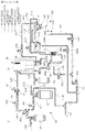
- FIG. 7 is a view illustrating a water treatment device according to an exemplary embodiment
- FIGS. 8 to 11 are views illustrating operations of a water treatment device according to an exemplary embodiment.
- a water treatment device 10 may include a filtration part 20, a storage part 30, a discharge part 40, a sterilizing part 50, and the sterilization water discharge device 100.
- the filtration part 20 may filter water supplied from a water supply source. To this end, the filtration part 20 may include water filters 21, 22 and 23.
- the filtration part 20 may be connected to the water supply source (not shown) as a raw water supply source, such as waterworks or the like, by a supply line LWS.
- a raw water supply source such as waterworks or the like
- a supply line LWS water from the water supply source, for example, raw water
- water from the water supply source may be supplied to the filtration part 20 through the supply line LWS, as illustrated in FIGS. 8 , 10 and 11 .
- the filtration part 20 may include a pretreatment filter 21, an reverse osmosis filter 22, and a post-treatment filter 23, as water filters 21, 22 and 23 as illustrated in FIG. 7 .
- the pretreatment filter 21, the reverse osmosis filter 22 and the post-treatment filter 23 may be connected to each other by connection lines LC1 and LC2.
- the pretreatment filter 21 may be connected to the water supply source by, for example, the supply line LWS as illustrated in FIG. 7 .
- the pretreatment filter 21 and the reverse osmosis filter 22 may be connected to each other by a first connection line LC1.
- the first connection line LC1 may be provided with a normal open valve VNO and a first supply valve VF1.
- the reverse osmosis filter 22 and the post-treatment filter 23 may be connected to each other by a second connection line LC2.
- the reverse osmosis filter 22 may be connected to a residential water line LLW.
- the residential water line LLW may be connected to a main drain line LDL.
- the residential water line LLW may be provided with a residential water valve VLW and a check valve CV.
- water supplied from the water supply source to the filtration part 20 may be sequentially filtered through the pretreatment filter 21, the reverse osmosis filter 22 and the post-treatment filter 23, as illustrated in FIGS. 8 and 11 .
- Water that has not been filtered by the reverse osmosis filter 22, for example, residential water, may be discharged externally through the residential water line LLW and the main drain line LDL.
- the normal open valve VNO may be closed to stop the supply of water from the water supply source to the filtration part 20.
- the water filtered by the filtration part 20 may be may be stored in the storage part 30.
- the storage part 30 may include, for example, a purified water tank 31, a cold water tank 32, and an instantaneous water heater 33 as illustrated in FIG. 7 .
- the purified water tank 31 may be connected to the filtration part 20, for example, the post-treatment filter 23 of the filtration part 20, by a storage line LST.
- the cold water tank 32 may be connected to the purified water tank 31, such that the water stored in the purified water tank 31 may be supplied and stored therein.
- the purified water tank 31 and the cold water tank 32 may be formed, by dividing one storage tank into portions in such a manner that the divided portions are communicated with each other by a separating member (not shown) formed with a plurality of communication holes (not shown).
- the cold water tank 32 may also be comprised of a storage tank, separately from the purified water tank 31, and the cold water tank 32 may be connected to the purified water tank 31 by a connection pipe or the like.
- the cold water tank 32 may not be connected to the purified water tank 31 but may be connected to the filtration part 20, separately from the purified water tank 31.
- the cold water tank 32 may be provided with a cooling part (not shown) such as an evaporator through which refrigerant flows, or a cooling part such as a thermoelectric module or the like, through which heat is transferred from one side to the other side when power is supplied. Water supplied to and stored in the cooling tank 32 may be cooled by the cooling part to become cold water.
- a cooling part such as an evaporator through which refrigerant flows, or a cooling part such as a thermoelectric module or the like, through which heat is transferred from one side to the other side when power is supplied. Water supplied to and stored in the cooling tank 32 may be cooled by the cooling part to become cold water.
- the cold water tank 32 may be connected to a tank drain line LTD connected to the sterilization water drain line LSD that is connected to the main drain line LDL.
- the tank drain line LTD may be provided with a tank drain valve VTD.
- the water stored in the cold water tank 32 and the purified water tank 31, for example, purified water and cold water may be discharged externally through the tank drain line LTD, the sterilization water drain line LSD and the main drain line LDL, as illustrated in FIG. 9 .
- the cold water and the purified water stored in the cold water tank 32 and the purified water tank 31, respectively may be drained externally to a low water level of the purified water tank 31, through the tank drain line LTD, the sterilization water drain line LSD and the main drain line LDL.
- a drainage amount of water stored in the cold water tank 32 and the purified water tank 31 is not particularly limited.
- the instantaneous water heater 33 may be connected to the purified water tank 31 by a first purified water supply line LPP1.
- the first purified water supply line LPP1 may be provided with a hot water discharge pump PHD and a flow rate sensor SF.
- water stored in the purified water tank 31, for example, purified water may be supplied to the instantaneous water heater 33 through the first purified water supply line LPP1, as illustrated in FIG. 8 .
- the instantaneous water heater 33 may include a heater 33a.
- the water supplied to the instantaneous water heater 33 for example, the purified water, may be heated by the heater 33a while flowing within the instantaneous water heater 33, thereby becoming hot water.
- the heater 33a may be, for example, a sheet-type heater.
- the heater 33a is not particularly limited, and any known device may be used as long as it can generate hot water by heating the water supplied to the instantaneous water heater 33.
- the discharge part 40 may discharge the water stored in the storage part 30 externally. To this end, the discharge part 40 may include the discharge member 41 connected to the storage part 30.
- the purified water connection port 41a may be provided in the discharge member 41.
- the purified cold water outlet 41d connected to the purified water connection port 41a as described above and illustrated in FIG. 2 may be provided in the discharge member 41.
- the purified water connection portion 41a may be connected directly to the purified water tank 31 by a purified water discharge line LPD. Further, the purified water discharge line LPD may be provided with a purified water discharge valve VPD.
- the purified water discharge valve VPD when the purified water discharge valve VPD is opened, the water stored in the purified water tank 31, for example, the purified water, may be discharged externally through the purified water discharge line LPD, the water connection portion 41a of the discharge member 41, and the purified cold water outlet 41d, as illustrated in FIG. 8 , to be supplied to a user.
- the tray part 200 of the sterilization water discharge device 100 since the tray part 200 of the sterilization water discharge device 100 according to an exemplary embodiment is in the standby position as illustrated in FIG. 8 , purified water may be discharged through the discharge member 41 without interference.
- the discharge member 41 may also be provided with the cold water connection port 41b.
- the cold water connection port 41b may be connected to the purified cold water outlet 41d.
- the cold water connection port 41b may be directly connected to the cold water tank 32 by the cold water discharge line LCD.
- the cold water discharge line LCD may be provided with a cold water discharge valve VCD.
- the cold water discharge line LCD may also be provided with a cold water discharge pump PCD.
- water stored in the cold water tank 32 for example, cold water
- water stored in the cold water tank 32 may be discharged through the cold water discharge line LCD, the cold water connection portion 41b of the discharge member 41, and the purified cold water outlet 41d, externally, as illustrated in FIG. 8 .
- the discharge member 41 may also be provided with the hot water connection port 41c.
- the discharge member 41 may be provided with the hot water outlet 41e formed therein, connected to the hot water connection port 41c as described above and illustrated in FIG. 2 .
- the hot water connection port 41c may be directly connected to the instantaneous water heater 33 by a hot water discharge line LHD. Further, the hot water discharge line LHD may be provided with a hot water discharge valve VHD.
- water produced by the instantaneous water heater 33 for example, hot water
- water produced by the instantaneous water heater 33 may be discharged externally through the hot water discharge line LHD, the hot water connection port 41c of the discharge member 41, and the hot water outlet 41e, to be supplied to a user, as illustrated in FIG. 8 .
- the tray part 200 of the sterilization water discharge device 100 since the tray part 200 of the sterilization water discharge device 100 according to the exemplary embodiment described above is in the standby position as illustrated in FIG. 8 , hot water may be discharged through the discharge member 41 without interference.
- the hot water discharge line LHD may be connected to a hot water drain line LHDL connected to the sterilization water drain line LSD.
- the hot water drain line LHDL may be provided with a hot water drain valve VHDL.
- the hot water drain valve VHDL may be opened to allow, hot water having a relatively low temperature in the hot water discharge line LHD, to be externally discharged through the hot water drain line LHDL, the sterilization water drain line LSD and the main drain line LDL.
- the relatively low temperature water in the hot water discharge line LHD may be prevented from being discharged through the discharge member 41, thereby allowing hot water, heated by the instantaneous heater 33, to have a predetermined temperature, to be discharged externally through the discharge member 41 from the beginning of discharge, and to be supplied to a user.
- sterilization water may be produced from water, for example, purified water, having been filtered by at least one of the water filters 21, 22 and 23 of the filtration part 20, to sterilize the storage part 30 and the discharge part 40.
- the sterilizing part 50 may, for example, produce sterilization water with water having been filtered by the pretreatment filter 21, for example, with purified water, as illustrated above with reference to FIG. 10 .
- the sterilizing part 50 may make sterilization water from water filtered by the pretreatment filter 21 and the reverse osmosis filter 22. Sterilization water may be produced using water filtered by any water filter 21, 22 or 23 included in the filtration part 20.
- the sterilizing part 50 may be connected to a first connection line LC1, connecting the pretreatment filter 21 and the reverse osmosis filter 22 to each other, by a second purified water supply line LPP2.
- the second purified water supply line LPP2 may be provided with a second supply valve VF2 and the check valve CV.
- the second supply valve VF2 when the second supply valve VF2 is opened, water supplied from the water supply source and filtered by the pretreatment filter 21, for example, the purified water, may be supplied to the sterilizing part 50, as illustrated in FIG. 10 .
- the sterilizing part 50 may include a sterilization water producing unit 51.
- the sterilization water producing unit 51 may be connected to the second purified water supply line LPP2 to receive water filtered by the pretreatment filter 21, for example, purified water. Then, the sterilization water producing unit 51 may be configured to electrolyze the received purified water to produce sterilization water.
- the sterilization water producing unit 51 is not particularly limited, and any known structure may be used as long as the sterilization water producing unit 51 may dissolve a sterilizing material in the received purified water to produce sterilization water.
- the sterilization water producing unit 51 of the sterilizing part 50 may be connected to the storage tank 30, for example, the purified water tank 31 of the storage part 30, by the sterilization water supply line LSP.
- the sterilization water produced in the sterilization water producing unit 51 may be supplied to the purified water tank 31 of the storage part 30 as illustrated in FIG. 10 .
- the sterilization water supplied to the purified water tank 31 of the storage part 30 may also be supplied to the cold water tank 32 of the storage part 30.
- the purified water tank 31 and the cold water tank 32 of the storage part 30 may be sterilized by sterilization water.
- the tray part 200 of the sterilization water discharge device 100 may move to the sterilization water drainage position as illustrated in FIG. 10 .
- the purified water discharge valve VPD and the cold water discharge valve VCD may be opened simultaneously or sequentially.
- the sterilization water having sterilized the purified water tank 31 and the cold water tank 32, may flow through the purified water discharge line LPD, the cold water discharge line LCD and the discharge member 41 of the discharge part 40 as illustrated in FIG. 10 , to sterilize the discharge lines LPD and LCD connecting the storage part 30 and the discharge member 41 of the discharge part 40 to each other, and the discharge part 40.
- the sterilization water having sterilized the discharge lines LPD and LCD and the discharge part 40, may be discharged from the discharge member 41 to be provided to the tray part 200 of the sterilization water discharge device 100 and then flow into the drain tank 500 as illustrated in FIG. 10 .
- sterilization water provided to the drain tank 500 may be externally discharged through the sterilization water drain line LSD and the main drain line LDL as illustrated in FIG. 10 .
- the water of the water supply source may be supplied to the filtration part 20 as illustrated in FIG. 11 , to rinse the storage part 30 and the discharge part 40 with the water filtered by the filtration part 20.
- the tray part 200 of the sterilization water discharge device 100 may be in the sterilization water drainage position as illustrated in FIG. 11 .
- the water having rinsed the storage part 30 and the discharge part 40 may be externally drained through the tray part 200, the drain tank 500, the sterilization water drain line LSD, and the main drain line LDL, as illustrated in FIG. 11 .
- the sterilization water discharge device As described above, the sterilization water discharge device according to an exemplary embodiment and the water treatment device including the same may be used.
- the tray part may be movably provided below the discharge member through which water is discharged, in such a manner that sterilization water discharged from the discharge member may be inserted thereinto to be drained.
- the drainage of sterilization water, having sterilized the water treatment device may be easily performed, and the sterilization water, having sterilized the water treatment device, may be smoothly drained.
- the sterilization water discharge device and the water treatment device including the same are not limited to the configurations of the exemplary embodiments described above, and the embodiments may also be variously modified by selectively combining all or some of the embodiments.
Landscapes
- Chemical & Material Sciences (AREA)
- Chemical Kinetics & Catalysis (AREA)
- Engineering & Computer Science (AREA)
- Water Supply & Treatment (AREA)
- Nanotechnology (AREA)
- Hydrology & Water Resources (AREA)
- Life Sciences & Earth Sciences (AREA)
- Environmental & Geological Engineering (AREA)
- Organic Chemistry (AREA)
- Devices For Dispensing Beverages (AREA)
- Apparatus For Disinfection Or Sterilisation (AREA)
- Separation Using Semi-Permeable Membranes (AREA)
- Heat Treatment Of Water, Waste Water Or Sewage (AREA)
- Water Treatment By Electricity Or Magnetism (AREA)
Abstract
Description
- The present disclosure relates to a sterilization water discharge device configured to receive sterilization water discharged from a discharge member, through which water is discharged, and to discharge the received sterilization water externally, and a water treatment device including the same.
- Water treatment devices are devices processing water to supply the processed water to users.
- As such water treatment devices, there are provided a water purifier for supplying water to a user by filtering the water, an ionizer for electrolyzing the water into alkaline water or acid water to supply the water to a user, a carbonated water generator for dissolving carbonic acid in water to supply the water to a user, and the like.
- On the other hand, when a water treatment device is used for an extended period of time, a storage tank in which water is stored, a tube through which water flows, or the like, may be contaminated by foreign substances, bacteria or the like. As such, when the water treatment device may be contaminated, the water treated in the water treatment device may also be contaminated such that contaminated water may be supplied to a user.
- Thus, sterilization water is produced in the related art water treatment device to sterilize the water treatment device periodically or when necessary.
- As described above, in the related art, sterilization water, having sterilized the water treatment device, is discharged through a discharge member that discharges treated-water processed by the water treatment device.
- Further, a separate drainage container is installed in the discharge member, so that sterilization water discharged from the discharge member may be provided to the drainage container. After the drainage container having the sterilization water therein is separated from the discharge member, the sterilization water stored in the drainage container is discarded.
- In this case, since the drainage container should be installed and separated from the discharge member every time the water treatment device is sterilized, it may be inconvenient for a user and the capacity of the drainage container is limited. Thus, the drainage of sterilization water may not be smoothly performed.
- An aspect of the present disclosure is to provide a sterilization water discharge device and a water treatment device by recognizing at least one of the above-mentioned requirements or problems in the related art.
- According to an aspect of the present disclosure, sterilization water, having sterilized a water treatment device, may be smoothly drained.
- According to another aspect of the present disclosure, the drainage of sterilization water having sterilized a water treatment device may be facilitated.
- A sterilization water discharge device and a water treatment device including the same, according to an exemplary embodiment in the present disclosure, may be characterized as described below.
- According to an aspect of the present disclosure, a sterilization water discharge device includes a tray part movably provided below a discharge member through which water is discharged, and configured to receive sterilization water discharged from the discharge member to drain the sterilization water; and a movement driving part configured to move the tray part.
- In this case, the tray part may move between a standby position, in which water other than the sterilization water, discharged from the discharge member, is not provided to the tray part, and a sterilization water drainage position, in which the sterilization water, discharged from the discharge member is provided to the tray part.
- The tray part may be provided with a sterilization water receiving portion formed therein, the sterilization water receiving portion having an open upper portion through which the sterilization water discharged from the discharge member is provided, and may be provided with a drainage port connected to the sterilization water receiving portion to drain the sterilization water contained in the sterilization water receiving portion.
- A bottom of the sterilization water receiving portion may be inclined toward the drainage port.
- The sterilization water discharge device may further include a movement guide part positioned below the discharge member and configured to allow the tray part to be movable.
- The movement guide part may include a water passage through which water other than sterilization water, discharged from the discharge member, passes and falls, in the standby position of the tray part, and a tray passage through which the tray part passes to move between the standby position and the sterilization water drainage position below the water passage.
- The movement guide part may further include a drainage port movement passage through which the drainage port passes and in which the drainage port is positioned and moves by movement of the tray part.
- The tray part may include a tray member that is provided with the sterilization water receiving portion and the drainage port; and a moving member in which an insertion portion is provided, into which the tray member is provided, the moving member being movably provided in the movement guide part.
- The moving member may be provided with a guide protrusion, and the movement guide part may be provided with a guide groove formed therein into which the guide protrusion is inserted and through which the guide protrusion moves.
- The movement guide part may be provided with a position sensor, sensing whether the tray part has moved to the sterilization water drainage position from the standby position.
- The movement guide part may be provided with a stopper member that prevents the tray part from moving further in a direction opposite to a direction of the sterilization water drainage position from the standby position.
- The sterilization water discharge device may further include a drain tank configured to receive sterilization water drained from the drainage port and to be connected to a sterilization water drain line to drain the sterilization water.
- The drain tank may be provided with a sterilization water receiving portion having an open upper portion through which the sterilization water drained from the drainage port is provided, and may be provided with a drain connection port connected to the sterilization water receiving portion and the sterilization water drain line.
- The sterilization water drain line may be provided with a drain pump.
- The drain tank may be provided with a water level sensor sensing a level of the sterilization water contained in the sterilization water receiving portion.
- The movement driving part may include a driving motor; and a gear connected to the driving motor and engaged with a gear portion disposed on the tray part.
- According to an aspect of the present disclosure, a water treatment device includes a filtration part including a water filter to filter water supplied from a water supply source; a storage part storing the water filtered by the filtration part; a discharge part including a discharge member externally discharging the water stored in the storage part; a sterilizing part producing sterilization water, using water filtered by at least one water filter in the water filter, to sterilize the storage part and the discharge part with sterilization water; and the sterilization water discharge device.
- The discharge member is directly connected to the storage part by a discharge line.
- As described above, according to exemplary embodiments in the present disclosure, a tray part may be movably provided below a discharge member from which water is discharged, to receive sterilization water discharged from the discharge member to drain the sterilization water.
- In addition, according to an exemplary embodiment, the drainage of sterilization water, having sterilized a water treatment device, may be easily performed.
- Further, according to an exemplary embodiment, sterilization water, having sterilized a water treatment device, may be smoothly drained.
-
-
FIG. 1 is a perspective view of a sterilization water discharge device according to an exemplary embodiment in the present disclosure. -
FIG. 2 is a perspective view of a sterilization water discharge device according to an exemplary embodiment, when viewed in a direction different from that inFIG. 1 . -
FIG. 3 is an exploded perspective view ofFIG. 1 . -
FIG. 4 is a cross-sectional view taken along line I-I' ofFIG. 1 . -
FIGS. 5 and6 are cross-sectional views illustrating operations of the sterilization water discharge device as illustrated inFIG. 4 , according to an exemplary embodiment in the present disclosure. -
FIG. 7 is a view illustrating a water treatment device according to an exemplary embodiment in the present disclosure. -
FIGS. 8 to 11 are views illustrating operations of a water treatment device according to an exemplary embodiment in the present disclosure. - Hereinafter, a sterilization water discharge device according to an exemplary embodiment in the present disclosure and a water treatment device including the same will be described in detail to facilitate understanding of the features of the present disclosure.
- Exemplary embodiments described below will be described on the basis of embodiments suited to understand the technical characteristics of the present disclosure, and the technical features of the present disclosure are not limited by the embodiments described below. Embodiments described below are provided to implement the invention by way of examples. Therefore, embodiments in the present disclosure may be variously modified within the technical scope of the invention, and the modifications and variations may be provided within the scope of the invention. In order to facilitate understanding of the embodiments described below, in the reference numerals illustrated in the accompanying drawings, the related constituent elements among the constituent elements performing the same function in respective embodiments are indicated by the same or similar reference numerals.
- Hereinafter, a sterilization water discharge device according to an exemplary embodiment will be described with reference to
FIGS. 1 to 6 . -
FIG. 1 is a perspective view of a sterilization water discharge device according to an exemplary embodiment, andFIG. 2 is a perspective view of a sterilization water discharge device according to an exemplary embodiment, when viewed in a direction different from that illustrated inFIG. 1 . -
FIG. 3 is an exploded perspective view ofFIG. 1 , andFIG. 4 is a cross-sectional view taken along line I-I' ofFIG. 1 . -
FIGS. 5 and6 are cross-sectional views illustrating operations of the sterilization water discharge device as illustrated inFIG. 4 , according to an exemplary embodiment. - A sterilization
water discharge device 100 according to an exemplary embodiment may include atray part 200 and amovement driving part 300, as illustrated inFIGS. 1 ,3 and4 . - The
tray part 200 may be movably provided below adischarge member 41. - Water, having been processed by a water treatment device to be described below, such as a water purifier including the
discharge member 41 or the like, may be discharged from thedischarge member 41. For example, as illustrated inFIG. 5 , purified water or purified cold water filtered bywater filters water treatment device 10, may be discharged from thedischarge member 41. - As illustrated in
FIG. 6 , sterilization water, for example, water having been produced in thewater treatment device 10 and having sterilized thewater treatment device 10, may be discharged from thedischarge member 41. - The
discharge member 41 may be, for example, a cock or a faucet, but is not particularly limited, and any known discharge member may be used as long as water and sterilization water can be discharged therethrough. - In the case in which the
discharge member 41 is included in thewater treatment device 10 such as a water purifier or the like, thedischarge member 41 may include a purifiedwater connection port 41a connected to apurified water tank 31 included in thewater treatment device 10, a coldwater connection port 41b connected to acold water tank 32, and a hotwater connection port 41c connected to aninstantaneous water heater 33, for example, as illustrated inFIGS. 1 and3 . - In addition, as illustrated in
FIG. 2 , thedischarge member 41 may be provided with a purifiedcold water outlet 41d connected to the purifiedwater connection port 41a and the coldwater connection port 41b, and ahot water outlet 41e connected to the hotwater connection port 41c. - Thus, purified water stored in the purified
water tank 31 of thewater treatment device 10 to be described later may be discharged through the purifiedwater connection port 41a and the purifiedcold water outlet 41d of thedischarge member 41. Further, cold water stored in thecold water tank 32 of thewater treatment device 10 to be described later may be discharged through the coldwater connection port 41b and the purifiedcold water outlet 41d of thedischarge member 41. Hot water produced by theinstantaneous water heater 33 of thewater treatment device 10 to be described later may be discharged through the hotwater connection port 41c and thehot water outlet 41e of thedischarge member 41. - In addition, sterilization water, having been produced by the
water treatment device 10 and having sterilized thewater treatment device 10, may be discharged through the purifiedwater connection port 41a and the purifiedcold water outlet 41d, or the coldwater connection port 41b and the purifiedcold water outlet 41d of thedischarge member 41. - However, the configuration and the number of the
discharge members 41 are not particularly limited, and any configuration and number ofdischarge members 41 may be employed, as long as water other than sterilization water, such as purified water, cold water, hot water or the like, and sterilization water, as described above, may be discharged thereby. - The
tray part 200 may be configured to receive sterilization water discharged from thedischarge member 41 and to drain the received sterilization water. - The
tray part 200 may be movable between a standby position as illustrated inFIG. 5 and a sterilization water drainage position as illustrated inFIG. 6 . - In the standby position, the
tray part 200 may not receive water other than sterilization water, discharged from thedischarge member 41. For example, purified water, cold water or hot water may not be provided to the tray part in the standby position. Further, in the sterilization water drainage position, thetray part 200 may receive sterilization water discharged from thedischarge member 41. - As a result, differently from the related art in which a separate drainage container (not shown) is installed in a discharge member to store sterilization water discharged from the discharge member and the drainage container is then separated from the discharge member to discard the sterilization water stored in the drainage container, sterilization water discharged from the
discharge member 41 may be drained by only moving thetray part 200 according to an exemplary embodiment in the present disclosure. - Thus, the drainage of sterilization water having sterilized the
water treatment device 10 may be easily performed. In addition, sterilization water having sterilized thewater treatment device 10 may be smoothly drained. - The
tray part 200 may be provided with a sterilizationwater receiving portion 211 formed therein, having an open upper portion. Thus, for example, when thetray part 200 is moved to the sterilization water drainage position as illustrated inFIG. 6 , sterilization water discharged from thedischarge member 41 may be received in the sterilizationwater receiving portion 211 through the open upper portion of the sterilizationwater receiving portion 211. - The
tray part 200 may include adrainage port 212. Thedrainage port 212 may be connected to the sterilizationwater receiving portion 211. Thus, for example, when thetray part 200 is moved to the sterilization water drainage position, the sterilization water discharged from thedischarge member 41 to be provided to the sterilizationwater receiving portion 211 may be drained through thedrainage port 212. - The bottom of the sterilization
water receiving portion 211 may be inclined toward thedrainage port 212 as illustrated inFIG. 4 . Thus, as illustrated inFIG. 6 , the sterilization water discharged from thedischarge member 41 and provided to the sterilizationwater receiving portion 211 may easily flow into thedrainage port 212 from the interior of the sterilizationwater receiving portion 211. - The
tray part 200 may be provided with agear portion 213 formed thereon. For example, thetray part 200 may be formed with thegear portion 213 that is a rack gear in a length direction. Agear 320 to be described later, included in themovement driving part 300, may be engaged with thegear portion 213. Thegear 320 may be, for example, a pinion gear. - Thus, the
tray part 200 may be moved between the standby position and the sterilization water drainage position, by rotation of thegear 320 by a drivingmotor 310 to be described later, included in themovement driving part 300 and connected to thegear 320, as illustrated inFIGS. 5 and6 . - The
tray part 200 may be provided with amagnet 214 as illustrated inFIG. 3 . Thus, aposition sensor 450 included in amovement guide part 400 to be described later may sense themagnet 214, to sense that thetray part 200 has moved to the sterilization water drainage position. - The
tray part 200 may include atray member 210 and a movingmember 220. - As illustrated in
FIGS. 3 and4 , thetray member 210 may be provided with the sterilizationwater receiving portion 211 formed therein, and may be provided with thedrainage port 212. In addition, thetray member 210 may be provided with thegear portion 213 described above and themagnet 214. - The moving
member 220 may be provided with aninsertion portion 221 formed therein, into which thetray member 210 may be inserted, as illustrated inFIGS. 3 and4 . Thetray member 210 may be combined with the movingmember 220, in a state being inserted into theinsertion portion 221 of the movingmember 220. - The moving
member 220 may be movably provided in themovement guide part 400. Thus, as the movingmember 220 moves in themovement guide part 400, thetray member 210 may also be moved. - The moving
member 220 may be provided with aguide protrusion 222 formed thereon. Theguide protrusion 222 may be movably inserted into aguide groove 440 to be described later, formed in themovement guide part 400, and thus, the movingmember 220 may be moved in themovement guide part 400. - However, the configuration in which the moving
member 220 is movably provided in themovement guide part 400, is not particularly limited, and any configuration known in the art may be applied thereto. - Further, the configuration of the
tray part 200 is not particularly limited, and any known configuration may be employed as long as thetray part 200 is configured to be movable below thedischarge member 41 and to receive sterilization water discharged from thedischarge member 41 to discharge the received sterilization water. - The
movement driving part 300 may be configured to move thetray part 200. Themovement driving part 300 may include the drivingmotor 310 and thegear 320 meshing with thegear portion 213, thegear portion 213 being disposed in thetray part 200, for example, provided with thetray member 210 of thetray part 200. - The
gear portion 213 of thetray part 200 may be, for example, a rack gear as described above, and thegear 320 may be, for example, a pinion gear. Thus, thetray part 200 may be moved by the rotation of thegear 320 as the drivingmotor 310 is driven. - However, the configuration of the
movement driving part 300 is not particularly limited, and any known configuration may be used as long as the configuration allows thetray part 200 to move. - The sterilization
water drainage device 100 according to an exemplary embodiment may further include themovement guide part 400 as illustrated inFIGS. 1 to 4 . - The
movement guide part 400 may be positioned below thedischarge member 41 as illustrated inFIGS. 1 ,2 and4 . For example, as illustrated in the drawing, themovement guide part 400 may be installed in a guide-part installation portion 11a formed in adevice body 11 included in thewater treatment device 10 such as a water purifier or the like, thereby being located below thedischarge member 41. - However, the configuration in which the
movement guide part 400 is positioned below thedischarge member 41 is not particularly limited, and any known configuration may be applied thereto. - The
movement guide part 400 may be provided with thetray part 200 provided movably. - The
movement guide part 400 may include awater passage 410 and atray passage 420. - Water, other than sterilization water discharged from the
discharge member 41, for example, water such as purified water, cold water or the like, treated by thewater treatment device 10, may pass through and fall through thewater passage 410, in the standby position of thetray part 200 as illustrated inFIG. 5 , so that water other than sterilization water may be supplied to a user. - In addition, the
tray part 200 may pass through thetray passage 420 to move between the standby position and the sterilization water drainage position below thewater passage 410. - As illustrated in
FIGS. 3 and4 , for example, thewater passage 410 may be horizontally formed in themovement guide part 400, and thetray passage 420 may be vertically formed in themovement guide part 400. Thewater passage 410 and thetray passage 420 may be connected to each other. - However, the configuration and shape of the
water passage 410 and thetray passage 420 are not particularly limited, and any configuration and shape may be used. - The
movement guide part 400 may further include a drainageport movement passage 430. As illustrated inFIG. 4 , thedrainage port 212 of thetray part 200 may pass through the drainageport movement passage 430. As thetray part 200 moves, thedrainage port 212 may be moved in the drainageport movement passage 430. - Thus, the movement of the
tray part 200 may be prevented from being disturbed by thedrainage port 212. - The
guide groove 440 may be formed in themovement guide part 400 . Theguide protrusion 222 of thetray part 200 described above may be movably inserted into theguide groove 440. For example, as illustrated inFIG. 3 , theguide groove 440 may be lengthwise respectively formed in portions of both sides of themovement guide part 400 provided on the drainageport movement passage 430 in a length direction of themovement guide part 400. Thus, thetray part 200 may be moved in themovement guide part 400. - However, the configuration in which the
tray part 200 is movably provided in themovement guide part 400 is not particularly limited, and any known configuration may be used. - In the
movement guide part 400, aposition sensor 450 may be provided to sense whether thetray part 200 has moved from the standby position to the sterilization water drainage position. - For example, the
position sensor 450 may be disposed in a portion of themovement guide part 400 to correspond to a position of the sterilization water drainage position of thetray part 200. In addition, theposition sensor 450 may sense themagnet 214 provided in thetray part 200. Thus, when thetray part 200 moves to the sterilization water drainage position, theposition sensor 450 may sense themagnet 214 of thetray part 200, to detect that thetray part 200 has moved to the sterilization water drainage position. - As such, for example, when the
tray part 200 is detected as having moved to the sterilization water drainage position by theposition sensor 450, sterilization water may be discharged from thedischarge member 41 as illustrated inFIG. 6 . Thus, the sterilization water discharged from thedischarge member 41 may be provided to thetray part 200 to be drained. - However, the configuration in which the
position sensor 450 senses that thetray part 200 has moved to the sterilization water drainage position is not particularly limited, and any known configuration may be employed. - The
movement guide part 400 may be provided with astopper member 460. Thestopper member 460 may prevent thetray part 200 from moving further in a direction opposite to that of the sterilization water drainage position, from the standby position. - For example, the
stopper member 460 may be provided on a portion of themovement guide part 400, corresponding to the standby position of thetray part 200, and may have the form of a '⊏'. Thus, after thetray part 200 is moved to the standby position by themovement driving part 300, thestopper member 460 may prevent thetray part 200 from moving further in the direction opposite to that of the sterilization water drainage position. - However, the position and the shape of the
stopper member 460 are not particularly limited, and any position and shape may be used as long as thetray part 200 may be prevented from moving in a direction opposite to that of the sterilization water drainage position from the standby position, in the position and shape. - As illustrated in
FIGS. 1 ,3 and4 , the sterilizationwater discharge device 100 according to an exemplary embodiment may further include adrain tank 500. - As illustrated in
FIG. 6 , thedrain tank 500 may contain sterilization water drained from thedrainage port 212 of thetray part 200. Then, thedrain tank 500 may be connected to a sterilization water drain line LSD as illustrated inFIG. 7 , such that sterilization water may be drained. - The
drain tank 500 may be located below thedrainage port 212 of thetray part 200. A sterilizationwater receiving portion 510 may be formed in thedrain tank 500, and the sterilizationwater receiving portion 510 may have an open upper portion through which sterilization water, drained from thedrainage port 212, may be provided to the sterilizationwater receiving portion 510. Further, thedrain tank 500 may be provided with adrain connection port 520 connected to the sterilizationwater receiving portion 510 and the sterilization water drain line LSD. - Thus, as illustrated in
FIG. 6 , sterilization water discharged from thedischarge member 41 and provided to thetray part 200, in the sterilization water drainage position of thetray part 200, may be discharged to thedrain tank 500 through thedrainage port 212, and may be provided to the sterilizationwater receiving portion 510 through the open upper portion of the sterilizationwater receiving portion 510. - In addition, the sterilization water provided to the sterilization
water receiving portion 510 of thedrain tank 500 may be introduced into the sterilization water drain line LSD through thedrain connection port 520, to be drained. - As illustrated in
FIG. 7 , the sterilization water drain line LSD may be provided with a drain pump PDL. The sterilization water provided to the sterilizationwater receiving portion 510 of thedrain tank 500 may be easily introduced into the sterilization water drain line LSD through thedrain connection port 520 to be drained, by driving the drain pump PDL. - The
drain tank 500 may be provided with a water level sensor (not shown) to sense the level of sterilization water provided to the sterilizationwater receiving portion 510. For example, at least one of a water level sensor sensing a low water level of sterilization water, and a water level sensor sensing a full water level of sterilization water may be provided in thedrain tank 500. - In addition, the sterilization water may be smoothly drained through the sterilization water drain line LSD, by adjusting driving of the drain pump PDL, depending on the water level of the sterilization water in the sterilization
water receiving portion 510 by the water level sensor. - Hereinafter, a water treatment device according to an exemplary embodiment in the present disclosure will be described with reference to
FIGS. 7 to 11 . -
FIG. 7 is a view illustrating a water treatment device according to an exemplary embodiment, andFIGS. 8 to 11 are views illustrating operations of a water treatment device according to an exemplary embodiment. - As illustrated in
FIG. 7 , awater treatment device 10 according to an exemplary embodiment may include afiltration part 20, astorage part 30, adischarge part 40, a sterilizingpart 50, and the sterilizationwater discharge device 100. - The
filtration part 20 may filter water supplied from a water supply source. To this end, thefiltration part 20 may include water filters 21, 22 and 23. - The
filtration part 20 may be connected to the water supply source (not shown) as a raw water supply source, such as waterworks or the like, by a supply line LWS. Thus, water from the water supply source, for example, raw water, may be supplied to thefiltration part 20 through the supply line LWS, as illustrated inFIGS. 8 ,10 and11 . - The
filtration part 20 may include apretreatment filter 21, anreverse osmosis filter 22, and apost-treatment filter 23, as water filters 21, 22 and 23 as illustrated inFIG. 7 . In this case, thepretreatment filter 21, thereverse osmosis filter 22 and thepost-treatment filter 23 may be connected to each other by connection lines LC1 and LC2. - The
pretreatment filter 21 may be connected to the water supply source by, for example, the supply line LWS as illustrated inFIG. 7 . In addition, thepretreatment filter 21 and thereverse osmosis filter 22 may be connected to each other by a first connection line LC1. The first connection line LC1 may be provided with a normal open valve VNO and a first supply valve VF1. - The
reverse osmosis filter 22 and thepost-treatment filter 23 may be connected to each other by a second connection line LC2. Thereverse osmosis filter 22 may be connected to a residential water line LLW. The residential water line LLW may be connected to a main drain line LDL. In addition, the residential water line LLW may be provided with a residential water valve VLW and a check valve CV. - In this configuration, when the first supply valve VF1 is opened, water supplied from the water supply source to the
filtration part 20 may be sequentially filtered through thepretreatment filter 21, thereverse osmosis filter 22 and thepost-treatment filter 23, as illustrated inFIGS. 8 and11 . - Water that has not been filtered by the
reverse osmosis filter 22, for example, residential water, may be discharged externally through the residential water line LLW and the main drain line LDL. - On the other hand, in an emergency, the normal open valve VNO may be closed to stop the supply of water from the water supply source to the
filtration part 20. - The water filtered by the
filtration part 20 may be may be stored in thestorage part 30. - The
storage part 30 may include, for example, apurified water tank 31, acold water tank 32, and aninstantaneous water heater 33 as illustrated inFIG. 7 . - The
purified water tank 31 may be connected to thefiltration part 20, for example, thepost-treatment filter 23 of thefiltration part 20, by a storage line LST. - The
cold water tank 32 may be connected to the purifiedwater tank 31, such that the water stored in the purifiedwater tank 31 may be supplied and stored therein. For example, the purifiedwater tank 31 and thecold water tank 32 may be formed, by dividing one storage tank into portions in such a manner that the divided portions are communicated with each other by a separating member (not shown) formed with a plurality of communication holes (not shown). - On the other hand, the
cold water tank 32 may also be comprised of a storage tank, separately from the purifiedwater tank 31, and thecold water tank 32 may be connected to the purifiedwater tank 31 by a connection pipe or the like. In addition, thecold water tank 32 may not be connected to the purifiedwater tank 31 but may be connected to thefiltration part 20, separately from the purifiedwater tank 31. - The
cold water tank 32 may be provided with a cooling part (not shown) such as an evaporator through which refrigerant flows, or a cooling part such as a thermoelectric module or the like, through which heat is transferred from one side to the other side when power is supplied. Water supplied to and stored in thecooling tank 32 may be cooled by the cooling part to become cold water. - The
cold water tank 32 may be connected to a tank drain line LTD connected to the sterilization water drain line LSD that is connected to the main drain line LDL. The tank drain line LTD may be provided with a tank drain valve VTD. - For example, when the tank drain valve VTD is opened, the water stored in the
cold water tank 32 and thepurified water tank 31, for example, purified water and cold water, may be discharged externally through the tank drain line LTD, the sterilization water drain line LSD and the main drain line LDL, as illustrated inFIG. 9 . - For example, the cold water and the purified water stored in the
cold water tank 32 and thepurified water tank 31, respectively, may be drained externally to a low water level of the purifiedwater tank 31, through the tank drain line LTD, the sterilization water drain line LSD and the main drain line LDL. However, a drainage amount of water stored in thecold water tank 32 and thepurified water tank 31 is not particularly limited. - In this case, when the drain pump PDL provided on the sterilization water drain line LSD is driven, the drainage of water of the
cold water tank 32 and thepurified water tank 31 may be smoothly performed. - The
instantaneous water heater 33 may be connected to the purifiedwater tank 31 by a first purified water supply line LPP1. The first purified water supply line LPP1 may be provided with a hot water discharge pump PHD and a flow rate sensor SF. In this case, for example, when the hot water discharge pump PHD is driven, water stored in the purifiedwater tank 31, for example, purified water, may be supplied to theinstantaneous water heater 33 through the first purified water supply line LPP1, as illustrated inFIG. 8 . - The
instantaneous water heater 33 may include aheater 33a. Thus, the water supplied to theinstantaneous water heater 33, for example, the purified water, may be heated by theheater 33a while flowing within theinstantaneous water heater 33, thereby becoming hot water. - The
heater 33a may be, for example, a sheet-type heater. However, theheater 33a is not particularly limited, and any known device may be used as long as it can generate hot water by heating the water supplied to theinstantaneous water heater 33. - A steam discharge line LVD, which is provided with the check valve CV, may be connected to the
instantaneous water heater 33. Steam generated when the water supplied to theinstantaneous water heater 33 is heated by theheater 33a as described above may be externally discharged through the steam discharge line LVD. - The
discharge part 40 may discharge the water stored in thestorage part 30 externally. To this end, thedischarge part 40 may include thedischarge member 41 connected to thestorage part 30. - The purified
water connection port 41a may be provided in thedischarge member 41. In addition, the purifiedcold water outlet 41d connected to the purifiedwater connection port 41a as described above and illustrated inFIG. 2 may be provided in thedischarge member 41. The purifiedwater connection portion 41a may be connected directly to the purifiedwater tank 31 by a purified water discharge line LPD. Further, the purified water discharge line LPD may be provided with a purified water discharge valve VPD. - Thus, for example, when the purified water discharge valve VPD is opened, the water stored in the purified
water tank 31, for example, the purified water, may be discharged externally through the purified water discharge line LPD, thewater connection portion 41a of thedischarge member 41, and the purifiedcold water outlet 41d, as illustrated inFIG. 8 , to be supplied to a user. - In this case, since the
tray part 200 of the sterilizationwater discharge device 100 according to an exemplary embodiment is in the standby position as illustrated inFIG. 8 , purified water may be discharged through thedischarge member 41 without interference. - The
discharge member 41 may also be provided with the coldwater connection port 41b. The coldwater connection port 41b may be connected to the purifiedcold water outlet 41d. The coldwater connection port 41b may be directly connected to thecold water tank 32 by the cold water discharge line LCD. In addition, the cold water discharge line LCD may be provided with a cold water discharge valve VCD. The cold water discharge line LCD may also be provided with a cold water discharge pump PCD. - Thus, for example, when the cold water discharge valve VCD is opened and the cold water discharge pump PCD is driven, water stored in the
cold water tank 32, for example, cold water, may be discharged through the cold water discharge line LCD, the coldwater connection portion 41b of thedischarge member 41, and the purifiedcold water outlet 41d, externally, as illustrated inFIG. 8 . - In this case, as described above, since the
tray part 200 of the sterilizationwater discharge device 100 according to an exemplary embodiment is in the standby position, cold water may be discharged through thedischarge member 41 without interference. - The
discharge member 41 may also be provided with the hotwater connection port 41c. In addition, thedischarge member 41 may be provided with thehot water outlet 41e formed therein, connected to the hotwater connection port 41c as described above and illustrated inFIG. 2 . The hotwater connection port 41c may be directly connected to theinstantaneous water heater 33 by a hot water discharge line LHD. Further, the hot water discharge line LHD may be provided with a hot water discharge valve VHD. - Thus, for example, when the hot water discharge valve VHD is opened, water produced by the
instantaneous water heater 33, for example, hot water, may be discharged externally through the hot water discharge line LHD, the hotwater connection port 41c of thedischarge member 41, and thehot water outlet 41e, to be supplied to a user, as illustrated inFIG. 8 . - In this case, since the
tray part 200 of the sterilizationwater discharge device 100 according to the exemplary embodiment described above is in the standby position as illustrated inFIG. 8 , hot water may be discharged through thedischarge member 41 without interference. - The hot water discharge line LHD may be connected to a hot water drain line LHDL connected to the sterilization water drain line LSD. The hot water drain line LHDL may be provided with a hot water drain valve VHDL.
- Thus, before the hot water produced in the
instantaneous water heater 33 is discharged through the hot water discharge line LHD and thedischarge member 41, the hot water drain valve VHDL may be opened to allow, hot water having a relatively low temperature in the hot water discharge line LHD, to be externally discharged through the hot water drain line LHDL, the sterilization water drain line LSD and the main drain line LDL. - Thus, at the beginning of the discharge of hot water through the
discharge member 41, the relatively low temperature water in the hot water discharge line LHD may be prevented from being discharged through thedischarge member 41, thereby allowing hot water, heated by theinstantaneous heater 33, to have a predetermined temperature, to be discharged externally through thedischarge member 41 from the beginning of discharge, and to be supplied to a user. - In the sterilizing
part 50, sterilization water may be produced from water, for example, purified water, having been filtered by at least one of the water filters 21, 22 and 23 of thefiltration part 20, to sterilize thestorage part 30 and thedischarge part 40. - The sterilizing
part 50 may, for example, produce sterilization water with water having been filtered by thepretreatment filter 21, for example, with purified water, as illustrated above with reference toFIG. 10 . The sterilizingpart 50 may make sterilization water from water filtered by thepretreatment filter 21 and thereverse osmosis filter 22. Sterilization water may be produced using water filtered by anywater filter filtration part 20. - The sterilizing
part 50 may be connected to a first connection line LC1, connecting thepretreatment filter 21 and thereverse osmosis filter 22 to each other, by a second purified water supply line LPP2. The second purified water supply line LPP2 may be provided with a second supply valve VF2 and the check valve CV. Thus, for example, when the second supply valve VF2 is opened, water supplied from the water supply source and filtered by thepretreatment filter 21, for example, the purified water, may be supplied to the sterilizingpart 50, as illustrated inFIG. 10 . - The sterilizing
part 50 may include a sterilizationwater producing unit 51. The sterilizationwater producing unit 51 may be connected to the second purified water supply line LPP2 to receive water filtered by thepretreatment filter 21, for example, purified water. Then, the sterilizationwater producing unit 51 may be configured to electrolyze the received purified water to produce sterilization water. - However, the sterilization
water producing unit 51 is not particularly limited, and any known structure may be used as long as the sterilizationwater producing unit 51 may dissolve a sterilizing material in the received purified water to produce sterilization water. - The sterilization
water producing unit 51 of the sterilizingpart 50 may be connected to thestorage tank 30, for example, the purifiedwater tank 31 of thestorage part 30, by the sterilization water supply line LSP. Thus, the sterilization water produced in the sterilizationwater producing unit 51 may be supplied to the purifiedwater tank 31 of thestorage part 30 as illustrated inFIG. 10 . - As such, the sterilization water supplied to the purified
water tank 31 of thestorage part 30 may also be supplied to thecold water tank 32 of thestorage part 30. Thepurified water tank 31 and thecold water tank 32 of thestorage part 30 may be sterilized by sterilization water. - In this case, the
tray part 200 of the sterilizationwater discharge device 100 according to an exemplary embodiment may move to the sterilization water drainage position as illustrated inFIG. 10 . - In addition, when the
tray part 200 is sensed as having moved to the sterilization water drainage position by theposition sensor 450 described above, the purified water discharge valve VPD and the cold water discharge valve VCD may be opened simultaneously or sequentially. - Thus, the sterilization water, having sterilized the purified
water tank 31 and thecold water tank 32, may flow through the purified water discharge line LPD, the cold water discharge line LCD and thedischarge member 41 of thedischarge part 40 as illustrated inFIG. 10 , to sterilize the discharge lines LPD and LCD connecting thestorage part 30 and thedischarge member 41 of thedischarge part 40 to each other, and thedischarge part 40. - As such, the sterilization water, having sterilized the discharge lines LPD and LCD and the
discharge part 40, may be discharged from thedischarge member 41 to be provided to thetray part 200 of the sterilizationwater discharge device 100 and then flow into thedrain tank 500 as illustrated inFIG. 10 . - For example, when the sterilization water drain valve VSD provided on the sterilization water drain line LSD is opened to drive the drain pump PDL, sterilization water provided to the
drain tank 500 may be externally discharged through the sterilization water drain line LSD and the main drain line LDL as illustrated inFIG. 10 . - As described above, after sterilizing the
storage part 30 and thedischarge part 40 by the sterilization water, the water of the water supply source may be supplied to thefiltration part 20 as illustrated inFIG. 11 , to rinse thestorage part 30 and thedischarge part 40 with the water filtered by thefiltration part 20. - In this case, the
tray part 200 of the sterilizationwater discharge device 100 according to an exemplary embodiment may be in the sterilization water drainage position as illustrated inFIG. 11 . - Thus, the water having rinsed the
storage part 30 and thedischarge part 40 may be externally drained through thetray part 200, thedrain tank 500, the sterilization water drain line LSD, and the main drain line LDL, as illustrated inFIG. 11 . - Since the sterilization
water discharge device 100 has been described above, the description thereof may be replaced with the foregoing description. - As described above, the sterilization water discharge device according to an exemplary embodiment and the water treatment device including the same may be used. In this case, the tray part may be movably provided below the discharge member through which water is discharged, in such a manner that sterilization water discharged from the discharge member may be inserted thereinto to be drained. Thus, the drainage of sterilization water, having sterilized the water treatment device, may be easily performed, and the sterilization water, having sterilized the water treatment device, may be smoothly drained.
- The sterilization water discharge device and the water treatment device including the same are not limited to the configurations of the exemplary embodiments described above, and the embodiments may also be variously modified by selectively combining all or some of the embodiments.
Claims (18)
- A sterilization water discharge device comprising:a tray part movably provided below a discharge member through which water is discharged, and configured to receive sterilization water discharged from the discharge member to drain the sterilization water; anda movement driving part configured to move the tray part.
- The sterilization water discharge device of claim 1, wherein the tray part moves between a standby position, in which water other than the sterilization water, discharged from the discharge member, is not provided to the tray part, and a sterilization water drainage position, in which the sterilization water, discharged from the discharge member is provided to the tray part.
- The sterilization water discharge device of claim 2, wherein the tray part is provided with a sterilization water receiving portion formed therein, the sterilization water receiving portion having an open upper portion through which the sterilization water discharged from the discharge member is provided, and is provided with a drainage port connected to the sterilization water receiving portion to drain the sterilization water contained in the sterilization water receiving portion.
- The sterilization water discharge device of claim 3, wherein a bottom of the sterilization water receiving portion is inclined toward the drainage port.
- The sterilization water discharge device of claim 3, further comprising a movement guide part positioned below the discharge member and configured to allow the tray part to be movable.
- The sterilization water discharge device of claim 5, wherein the movement guide part comprises a water passage through which water other than sterilization water, discharged from the discharge member, passes and falls, in the standby position of the tray part, and a tray passage through which the tray part passes to move between the standby position and the sterilization water drainage position below the water passage.
- The sterilization water discharge device of claim 6, wherein the movement guide part further comprises a drainage port movement passage through which the drainage port passes and in which the drainage port is positioned and moves by movement of the tray part.
- The sterilization water discharge device of claim 6, wherein the tray part comprises:a tray member that is provided with the sterilization water receiving portion and the drainage port; anda moving member in which an insertion portion is provided, into which the tray member is inserted, the moving member being movably provided in the movement guide part.
- The sterilization water discharge device of claim 8, wherein the moving member is provided with a guide protrusion, and the movement guide part is provided with a guide groove formed therein into which the guide protrusion is inserted and through which the guide protrusion moves.
- The sterilization water discharge device of claim 5, wherein the movement guide part is provided with a position sensor sensing whether the tray part has moved to the sterilization water drainage position from the standby position.
- The sterilization water discharge device of claim 5, wherein the movement guide part is provided with a stopper member that prevents the tray part from moving further in a direction opposite to a direction of the sterilization water drainage position from the standby position.
- The sterilization water discharge device of claim 3, further comprising a drain tank configured to receive sterilization water drained from the drainage port and to be connected to a sterilization water drain line to drain the sterilization water.
- The sterilization water discharge device of claim 12, wherein the drain tank is provided with a sterilization water receiving portion having an open upper portion through which the sterilization water drained from the drainage port is provided, and is provided with a drain connection port connected to the sterilization water receiving portion and the sterilization water drain line.
- The sterilization water discharge device of claim 12, wherein the sterilization water drain line is provided with a drain pump.
- The sterilization water discharge device of claim 12, wherein the drain tank is provided with a water level sensor sensing a level of the sterilization water contained in the sterilization water receiving portion.
- The sterilization water discharge device of claim 1, wherein the movement driving part comprises:a driving motor; anda gear connected to the driving motor and engaged with a gear portion disposed on the tray part.
- A water treatment device comprising:a filtration part including a water filter to filter water supplied from a water supply source;a storage part storing the water filtered by the filtration part;a discharge part including a discharge member externally discharging the water stored in the storage part;a sterilizing part producing sterilization water, using water filtered by at least one water filter in the water filter, to sterilize the storage part and the discharge part with sterilization water; andthe sterilization water discharge device according to any one of claims 1 to 16.
- The water treatment device of claim 17, wherein the discharge member is directly connected to the storage part by a discharge line.
Applications Claiming Priority (2)
| Application Number | Priority Date | Filing Date | Title |
|---|---|---|---|
| KR1020160053832A KR102572502B1 (en) | 2016-05-02 | 2016-05-02 | Sterilization water draining apparatus and water treatment apparatus having the same |
| PCT/KR2017/004685 WO2017192002A1 (en) | 2016-05-02 | 2017-05-02 | Sterilization water discharge device and water treatment device including same |
Publications (3)
| Publication Number | Publication Date |
|---|---|
| EP3453439A1 true EP3453439A1 (en) | 2019-03-13 |
| EP3453439A4 EP3453439A4 (en) | 2019-04-03 |
| EP3453439B1 EP3453439B1 (en) | 2021-03-10 |
Family
ID=60202975
Family Applications (1)
| Application Number | Title | Priority Date | Filing Date |
|---|---|---|---|
| EP17792904.9A Active EP3453439B1 (en) | 2016-05-02 | 2017-05-02 | Water treatment device including a sterilization water discharge device |
Country Status (6)
| Country | Link |
|---|---|
| US (1) | US10898837B2 (en) |
| EP (1) | EP3453439B1 (en) |
| KR (1) | KR102572502B1 (en) |
| CN (2) | CN113101736B (en) |
| ES (1) | ES2871798T3 (en) |
| WO (1) | WO2017192002A1 (en) |
Families Citing this family (2)
| Publication number | Priority date | Publication date | Assignee | Title |
|---|---|---|---|---|
| KR102710714B1 (en) * | 2018-07-16 | 2024-09-27 | 코웨이 주식회사 | Tank for treating overheated water |
| USD966461S1 (en) * | 2021-02-16 | 2022-10-11 | Toddy, Llc. | Filtration system |
Family Cites Families (18)
| Publication number | Priority date | Publication date | Assignee | Title |
|---|---|---|---|---|
| KR0161071B1 (en) | 1995-12-30 | 1998-11-16 | 김광호 | Apparatus for convert of drain |
| KR100232848B1 (en) * | 1997-08-30 | 1999-12-01 | 윤종용 | Water supply regulator of the refrigerator |
| KR19990016970U (en) * | 1997-10-31 | 1999-05-25 | 전주범 | Automatic drainage device for water purifier |
| US7470364B2 (en) * | 2004-04-02 | 2008-12-30 | Tanna Industries (1991) Ltd. | Water dispenser and filter cartridge for use therein |
| US7455085B2 (en) * | 2004-06-04 | 2008-11-25 | Whirlpool Corporation | Water dispenser for refrigerator freezers |
| EP1639881B1 (en) * | 2004-09-28 | 2007-11-14 | Deere & Company | Round Baler |
| KR100666557B1 (en) * | 2005-05-16 | 2007-01-09 | 위니아만도 주식회사 | Water level detection method of water tank and water purifier control method |
| HK1095979A2 (en) | 2006-06-13 | 2007-05-18 | 屈臣氏企业有限公司 | Water dispenser |
| CN200998164Y (en) * | 2007-01-04 | 2008-01-02 | 吴钟茂 | Domestic drinking water machine with water preparation |
| KR101100967B1 (en) * | 2009-12-01 | 2011-12-29 | 엘지전자 주식회사 | water purifier |
| EP2571594B1 (en) | 2010-05-19 | 2020-02-19 | Woongjin Coway Co., Ltd. | Water treatment apparatus and sterilizing and cleansing method thereof |
| KR20110127588A (en) | 2010-05-19 | 2011-11-25 | 웅진코웨이주식회사 | Sterilizing water purifier |
| KR101686131B1 (en) * | 2010-06-28 | 2016-12-14 | 코웨이 주식회사 | Water purifier for automatic sterilization |
| EP3056842B1 (en) | 2013-02-20 | 2017-10-04 | LG Electronics Inc. | Refrigerator |
| CN203399999U (en) | 2013-08-19 | 2014-01-22 | 深圳安吉尔饮水产业集团有限公司 | Cold and hot water drinking device with sterilization function |
| CN204111498U (en) * | 2014-09-29 | 2015-01-21 | 浙江沁园水处理科技有限公司 | A kind of saving type water purification machine with sterilizing unit |
| CN204417266U (en) * | 2014-12-23 | 2015-06-24 | 修建东 | A kind of home-use reverse osmosis water maker |
| CN204813415U (en) | 2015-07-16 | 2015-12-02 | 依莱克顿(宁波)电器科技有限公司 | Water dispenser with sterilization system |
-
2016
- 2016-05-02 KR KR1020160053832A patent/KR102572502B1/en active Active
-
2017
- 2017-05-02 EP EP17792904.9A patent/EP3453439B1/en active Active
- 2017-05-02 CN CN202110400372.3A patent/CN113101736B/en active Active
- 2017-05-02 US US16/098,332 patent/US10898837B2/en active Active
- 2017-05-02 ES ES17792904T patent/ES2871798T3/en active Active
- 2017-05-02 CN CN201780027188.0A patent/CN109069958B/en active Active
- 2017-05-02 WO PCT/KR2017/004685 patent/WO2017192002A1/en not_active Ceased
Also Published As
| Publication number | Publication date |
|---|---|
| US20190118123A1 (en) | 2019-04-25 |
| EP3453439B1 (en) | 2021-03-10 |
| CN109069958A (en) | 2018-12-21 |
| CN113101736A (en) | 2021-07-13 |
| WO2017192002A1 (en) | 2017-11-09 |
| EP3453439A4 (en) | 2019-04-03 |
| CN109069958B (en) | 2021-06-25 |
| KR102572502B1 (en) | 2023-08-30 |
| US10898837B2 (en) | 2021-01-26 |
| CN113101736B (en) | 2023-04-11 |
| KR20170124217A (en) | 2017-11-10 |
| ES2871798T3 (en) | 2021-11-02 |
Similar Documents
| Publication | Publication Date | Title |
|---|---|---|
| KR101717109B1 (en) | Method for sterilizing a water supply apparatus | |
| CN105776685B (en) | Water purifier | |
| KR101293233B1 (en) | Water purifier | |
| EP3453439B1 (en) | Water treatment device including a sterilization water discharge device | |
| KR20130025801A (en) | water purifier | |
| KR20140121234A (en) | Water treatment apparatus having ice manufacturing function and the method thereof | |
| US20190111365A1 (en) | Water treatment apparatus | |
| KR20140131615A (en) | water purifier and a control method of the same | |
| KR101305329B1 (en) | Water purifier | |
| KR101305331B1 (en) | Water purifier | |
| KR20170068926A (en) | Water purifier having sterilizing function using carbonated water | |
| KR101305330B1 (en) | Water purifier | |
| KR102844647B1 (en) | Water treatment apparatus having ice manufacturing function and the control method thereof | |
| KR20170073313A (en) | Apparatus and method for supplying filtered water | |
| KR20190096763A (en) | Sterilizing method of water treatment apparatus | |
| KR20130006014A (en) | Sterilization method of water purifier | |
| KR20180078613A (en) | Water purifier | |
| KR101476323B1 (en) | Water treatment apparatus and water treatment method | |
| KR101447963B1 (en) | Water treatment method | |
| US20240132386A1 (en) | Water purifier | |
| KR102710715B1 (en) | Water treatment apparatus and operating method thereof | |
| KR20220153290A (en) | Water purifier | |
| KR101304818B1 (en) | Water purifier sterilization apparatus | |
| KR20150057528A (en) | Hot and cool ionization water purifier | |
| CN107215924A (en) | A kind of efficient water purifier and cabinet |
Legal Events
| Date | Code | Title | Description |
|---|---|---|---|
| STAA | Information on the status of an ep patent application or granted ep patent |
Free format text: STATUS: THE INTERNATIONAL PUBLICATION HAS BEEN MADE |
|
| PUAI | Public reference made under article 153(3) epc to a published international application that has entered the european phase |
Free format text: ORIGINAL CODE: 0009012 |
|
| STAA | Information on the status of an ep patent application or granted ep patent |
Free format text: STATUS: REQUEST FOR EXAMINATION WAS MADE |
|
| 17P | Request for examination filed |
Effective date: 20181127 |
|
| AK | Designated contracting states |
Kind code of ref document: A1 Designated state(s): AL AT BE BG CH CY CZ DE DK EE ES FI FR GB GR HR HU IE IS IT LI LT LU LV MC MK MT NL NO PL PT RO RS SE SI SK SM TR |
|
| AX | Request for extension of the european patent |
Extension state: BA ME |
|
| A4 | Supplementary search report drawn up and despatched |
Effective date: 20190306 |
|
| RIC1 | Information provided on ipc code assigned before grant |
Ipc: C02F 1/00 20060101ALI20190228BHEP Ipc: B67D 1/07 20060101ALI20190228BHEP Ipc: B01D 61/02 20060101ALN20190228BHEP Ipc: B01D 35/14 20060101AFI20190228BHEP Ipc: C02F 1/44 20060101ALN20190228BHEP Ipc: B01D 35/16 20060101ALI20190228BHEP Ipc: C02F 1/46 20060101ALN20190228BHEP |
|
| DAV | Request for validation of the european patent (deleted) | ||
| DAX | Request for extension of the european patent (deleted) | ||
| STAA | Information on the status of an ep patent application or granted ep patent |
Free format text: STATUS: EXAMINATION IS IN PROGRESS |
|
| 17Q | First examination report despatched |
Effective date: 20200508 |
|
| REG | Reference to a national code |
Ref country code: DE Ref legal event code: R079 Ref document number: 602017034428 Country of ref document: DE Free format text: PREVIOUS MAIN CLASS: B01D0035040000 Ipc: B01D0035140000 |
|
| GRAP | Despatch of communication of intention to grant a patent |
Free format text: ORIGINAL CODE: EPIDOSNIGR1 |
|
| STAA | Information on the status of an ep patent application or granted ep patent |
Free format text: STATUS: GRANT OF PATENT IS INTENDED |
|
| RIC1 | Information provided on ipc code assigned before grant |
Ipc: B67D 1/07 20060101ALI20200929BHEP Ipc: C02F 1/00 20060101ALI20200929BHEP Ipc: B01D 61/02 20060101ALN20200929BHEP Ipc: B01D 35/16 20060101ALI20200929BHEP Ipc: C02F 1/46 20060101ALN20200929BHEP Ipc: B01D 35/14 20060101AFI20200929BHEP Ipc: C02F 1/44 20060101ALN20200929BHEP |
|
| INTG | Intention to grant announced |
Effective date: 20201016 |
|
| GRAS | Grant fee paid |
Free format text: ORIGINAL CODE: EPIDOSNIGR3 |
|
| GRAA | (expected) grant |
Free format text: ORIGINAL CODE: 0009210 |
|
| STAA | Information on the status of an ep patent application or granted ep patent |
Free format text: STATUS: THE PATENT HAS BEEN GRANTED |
|
| AK | Designated contracting states |
Kind code of ref document: B1 Designated state(s): AL AT BE BG CH CY CZ DE DK EE ES FI FR GB GR HR HU IE IS IT LI LT LU LV MC MK MT NL NO PL PT RO RS SE SI SK SM TR |
|
| REG | Reference to a national code |
Ref country code: GB Ref legal event code: FG4D |
|
| REG | Reference to a national code |
Ref country code: AT Ref legal event code: REF Ref document number: 1369200 Country of ref document: AT Kind code of ref document: T Effective date: 20210315 Ref country code: CH Ref legal event code: EP |
|
| REG | Reference to a national code |
Ref country code: IE Ref legal event code: FG4D |
|
| REG | Reference to a national code |
Ref country code: DE Ref legal event code: R096 Ref document number: 602017034428 Country of ref document: DE |
|
| REG | Reference to a national code |
Ref country code: LT Ref legal event code: MG9D |
|
| PG25 | Lapsed in a contracting state [announced via postgrant information from national office to epo] |
Ref country code: GR Free format text: LAPSE BECAUSE OF FAILURE TO SUBMIT A TRANSLATION OF THE DESCRIPTION OR TO PAY THE FEE WITHIN THE PRESCRIBED TIME-LIMIT Effective date: 20210611 Ref country code: HR Free format text: LAPSE BECAUSE OF FAILURE TO SUBMIT A TRANSLATION OF THE DESCRIPTION OR TO PAY THE FEE WITHIN THE PRESCRIBED TIME-LIMIT Effective date: 20210310 Ref country code: FI Free format text: LAPSE BECAUSE OF FAILURE TO SUBMIT A TRANSLATION OF THE DESCRIPTION OR TO PAY THE FEE WITHIN THE PRESCRIBED TIME-LIMIT Effective date: 20210310 Ref country code: NO Free format text: LAPSE BECAUSE OF FAILURE TO SUBMIT A TRANSLATION OF THE DESCRIPTION OR TO PAY THE FEE WITHIN THE PRESCRIBED TIME-LIMIT Effective date: 20210610 Ref country code: BG Free format text: LAPSE BECAUSE OF FAILURE TO SUBMIT A TRANSLATION OF THE DESCRIPTION OR TO PAY THE FEE WITHIN THE PRESCRIBED TIME-LIMIT Effective date: 20210610 Ref country code: LT Free format text: LAPSE BECAUSE OF FAILURE TO SUBMIT A TRANSLATION OF THE DESCRIPTION OR TO PAY THE FEE WITHIN THE PRESCRIBED TIME-LIMIT Effective date: 20210310 |
|
| REG | Reference to a national code |
Ref country code: AT Ref legal event code: MK05 Ref document number: 1369200 Country of ref document: AT Kind code of ref document: T Effective date: 20210310 |
|
| REG | Reference to a national code |
Ref country code: NL Ref legal event code: MP Effective date: 20210310 |
|
| PG25 | Lapsed in a contracting state [announced via postgrant information from national office to epo] |
Ref country code: RS Free format text: LAPSE BECAUSE OF FAILURE TO SUBMIT A TRANSLATION OF THE DESCRIPTION OR TO PAY THE FEE WITHIN THE PRESCRIBED TIME-LIMIT Effective date: 20210310 Ref country code: LV Free format text: LAPSE BECAUSE OF FAILURE TO SUBMIT A TRANSLATION OF THE DESCRIPTION OR TO PAY THE FEE WITHIN THE PRESCRIBED TIME-LIMIT Effective date: 20210310 Ref country code: SE Free format text: LAPSE BECAUSE OF FAILURE TO SUBMIT A TRANSLATION OF THE DESCRIPTION OR TO PAY THE FEE WITHIN THE PRESCRIBED TIME-LIMIT Effective date: 20210310 |
|
| PG25 | Lapsed in a contracting state [announced via postgrant information from national office to epo] |
Ref country code: NL Free format text: LAPSE BECAUSE OF FAILURE TO SUBMIT A TRANSLATION OF THE DESCRIPTION OR TO PAY THE FEE WITHIN THE PRESCRIBED TIME-LIMIT Effective date: 20210310 |
|
| PG25 | Lapsed in a contracting state [announced via postgrant information from national office to epo] |
Ref country code: CZ Free format text: LAPSE BECAUSE OF FAILURE TO SUBMIT A TRANSLATION OF THE DESCRIPTION OR TO PAY THE FEE WITHIN THE PRESCRIBED TIME-LIMIT Effective date: 20210310 Ref country code: EE Free format text: LAPSE BECAUSE OF FAILURE TO SUBMIT A TRANSLATION OF THE DESCRIPTION OR TO PAY THE FEE WITHIN THE PRESCRIBED TIME-LIMIT Effective date: 20210310 Ref country code: AT Free format text: LAPSE BECAUSE OF FAILURE TO SUBMIT A TRANSLATION OF THE DESCRIPTION OR TO PAY THE FEE WITHIN THE PRESCRIBED TIME-LIMIT Effective date: 20210310 Ref country code: SM Free format text: LAPSE BECAUSE OF FAILURE TO SUBMIT A TRANSLATION OF THE DESCRIPTION OR TO PAY THE FEE WITHIN THE PRESCRIBED TIME-LIMIT Effective date: 20210310 |
|
| REG | Reference to a national code |
Ref country code: ES Ref legal event code: FG2A Ref document number: 2871798 Country of ref document: ES Kind code of ref document: T3 Effective date: 20211102 |
|
| PG25 | Lapsed in a contracting state [announced via postgrant information from national office to epo] |
Ref country code: IS Free format text: LAPSE BECAUSE OF FAILURE TO SUBMIT A TRANSLATION OF THE DESCRIPTION OR TO PAY THE FEE WITHIN THE PRESCRIBED TIME-LIMIT Effective date: 20210710 Ref country code: PL Free format text: LAPSE BECAUSE OF FAILURE TO SUBMIT A TRANSLATION OF THE DESCRIPTION OR TO PAY THE FEE WITHIN THE PRESCRIBED TIME-LIMIT Effective date: 20210310 Ref country code: PT Free format text: LAPSE BECAUSE OF FAILURE TO SUBMIT A TRANSLATION OF THE DESCRIPTION OR TO PAY THE FEE WITHIN THE PRESCRIBED TIME-LIMIT Effective date: 20210712 Ref country code: RO Free format text: LAPSE BECAUSE OF FAILURE TO SUBMIT A TRANSLATION OF THE DESCRIPTION OR TO PAY THE FEE WITHIN THE PRESCRIBED TIME-LIMIT Effective date: 20210310 Ref country code: SK Free format text: LAPSE BECAUSE OF FAILURE TO SUBMIT A TRANSLATION OF THE DESCRIPTION OR TO PAY THE FEE WITHIN THE PRESCRIBED TIME-LIMIT Effective date: 20210310 |
|
| REG | Reference to a national code |
Ref country code: DE Ref legal event code: R097 Ref document number: 602017034428 Country of ref document: DE |
|
| REG | Reference to a national code |
Ref country code: CH Ref legal event code: PL |
|
| PLBE | No opposition filed within time limit |
Free format text: ORIGINAL CODE: 0009261 |
|
| STAA | Information on the status of an ep patent application or granted ep patent |
Free format text: STATUS: NO OPPOSITION FILED WITHIN TIME LIMIT |
|
| PG25 | Lapsed in a contracting state [announced via postgrant information from national office to epo] |
Ref country code: AL Free format text: LAPSE BECAUSE OF FAILURE TO SUBMIT A TRANSLATION OF THE DESCRIPTION OR TO PAY THE FEE WITHIN THE PRESCRIBED TIME-LIMIT Effective date: 20210310 Ref country code: DK Free format text: LAPSE BECAUSE OF FAILURE TO SUBMIT A TRANSLATION OF THE DESCRIPTION OR TO PAY THE FEE WITHIN THE PRESCRIBED TIME-LIMIT Effective date: 20210310 Ref country code: CH Free format text: LAPSE BECAUSE OF NON-PAYMENT OF DUE FEES Effective date: 20210531 Ref country code: LI Free format text: LAPSE BECAUSE OF NON-PAYMENT OF DUE FEES Effective date: 20210531 Ref country code: LU Free format text: LAPSE BECAUSE OF NON-PAYMENT OF DUE FEES Effective date: 20210502 Ref country code: MC Free format text: LAPSE BECAUSE OF FAILURE TO SUBMIT A TRANSLATION OF THE DESCRIPTION OR TO PAY THE FEE WITHIN THE PRESCRIBED TIME-LIMIT Effective date: 20210310 |
|
| REG | Reference to a national code |
Ref country code: BE Ref legal event code: MM Effective date: 20210531 |
|
| 26N | No opposition filed |
Effective date: 20211213 |
|
| GBPC | Gb: european patent ceased through non-payment of renewal fee |
Effective date: 20210610 |
|
| PG25 | Lapsed in a contracting state [announced via postgrant information from national office to epo] |
Ref country code: SI Free format text: LAPSE BECAUSE OF FAILURE TO SUBMIT A TRANSLATION OF THE DESCRIPTION OR TO PAY THE FEE WITHIN THE PRESCRIBED TIME-LIMIT Effective date: 20210310 |
|
| PG25 | Lapsed in a contracting state [announced via postgrant information from national office to epo] |
Ref country code: IE Free format text: LAPSE BECAUSE OF NON-PAYMENT OF DUE FEES Effective date: 20210502 Ref country code: GB Free format text: LAPSE BECAUSE OF NON-PAYMENT OF DUE FEES Effective date: 20210610 |
|
| PG25 | Lapsed in a contracting state [announced via postgrant information from national office to epo] |
Ref country code: IS Free format text: LAPSE BECAUSE OF FAILURE TO SUBMIT A TRANSLATION OF THE DESCRIPTION OR TO PAY THE FEE WITHIN THE PRESCRIBED TIME-LIMIT Effective date: 20210710 |
|
| PG25 | Lapsed in a contracting state [announced via postgrant information from national office to epo] |
Ref country code: BE Free format text: LAPSE BECAUSE OF NON-PAYMENT OF DUE FEES Effective date: 20210531 |
|
| PG25 | Lapsed in a contracting state [announced via postgrant information from national office to epo] |
Ref country code: CY Free format text: LAPSE BECAUSE OF FAILURE TO SUBMIT A TRANSLATION OF THE DESCRIPTION OR TO PAY THE FEE WITHIN THE PRESCRIBED TIME-LIMIT Effective date: 20210310 |
|
| PG25 | Lapsed in a contracting state [announced via postgrant information from national office to epo] |
Ref country code: HU Free format text: LAPSE BECAUSE OF FAILURE TO SUBMIT A TRANSLATION OF THE DESCRIPTION OR TO PAY THE FEE WITHIN THE PRESCRIBED TIME-LIMIT; INVALID AB INITIO Effective date: 20170502 |
|
| PG25 | Lapsed in a contracting state [announced via postgrant information from national office to epo] |
Ref country code: MK Free format text: LAPSE BECAUSE OF FAILURE TO SUBMIT A TRANSLATION OF THE DESCRIPTION OR TO PAY THE FEE WITHIN THE PRESCRIBED TIME-LIMIT Effective date: 20210310 |
|
| PG25 | Lapsed in a contracting state [announced via postgrant information from national office to epo] |
Ref country code: MT Free format text: LAPSE BECAUSE OF FAILURE TO SUBMIT A TRANSLATION OF THE DESCRIPTION OR TO PAY THE FEE WITHIN THE PRESCRIBED TIME-LIMIT Effective date: 20210310 |
|
| PGFP | Annual fee paid to national office [announced via postgrant information from national office to epo] |
Ref country code: IT Payment date: 20250321 Year of fee payment: 9 |
|
| PGFP | Annual fee paid to national office [announced via postgrant information from national office to epo] |
Ref country code: DE Payment date: 20250320 Year of fee payment: 9 |
|
| PGFP | Annual fee paid to national office [announced via postgrant information from national office to epo] |
Ref country code: ES Payment date: 20250613 Year of fee payment: 9 |
|
| PG25 | Lapsed in a contracting state [announced via postgrant information from national office to epo] |
Ref country code: TR Free format text: LAPSE BECAUSE OF FAILURE TO SUBMIT A TRANSLATION OF THE DESCRIPTION OR TO PAY THE FEE WITHIN THE PRESCRIBED TIME-LIMIT Effective date: 20210310 |
|
| PGFP | Annual fee paid to national office [announced via postgrant information from national office to epo] |
Ref country code: FR Payment date: 20260323 Year of fee payment: 10 |