EP3453363A1 - Tool for fixed customised relative alignment of adjustable orthopedic devices - Google Patents
Tool for fixed customised relative alignment of adjustable orthopedic devices Download PDFInfo
- Publication number
- EP3453363A1 EP3453363A1 EP18168424.2A EP18168424A EP3453363A1 EP 3453363 A1 EP3453363 A1 EP 3453363A1 EP 18168424 A EP18168424 A EP 18168424A EP 3453363 A1 EP3453363 A1 EP 3453363A1
- Authority
- EP
- European Patent Office
- Prior art keywords
- plate
- simulator
- alignment
- anatomy
- alignment mechanism
- Prior art date
- Legal status (The legal status is an assumption and is not a legal conclusion. Google has not performed a legal analysis and makes no representation as to the accuracy of the status listed.)
- Granted
Links
Images



Classifications
-
- A—HUMAN NECESSITIES
- A61—MEDICAL OR VETERINARY SCIENCE; HYGIENE
- A61B—DIAGNOSIS; SURGERY; IDENTIFICATION
- A61B34/00—Computer-aided surgery; Manipulators or robots specially adapted for use in surgery
- A61B34/10—Computer-aided planning, simulation or modelling of surgical operations
-
- A—HUMAN NECESSITIES
- A61—MEDICAL OR VETERINARY SCIENCE; HYGIENE
- A61B—DIAGNOSIS; SURGERY; IDENTIFICATION
- A61B17/00—Surgical instruments, devices or methods
- A61B17/16—Instruments for performing osteoclasis; Drills or chisels for bones; Trepans
- A61B17/17—Guides or aligning means for drills, mills, pins or wires
- A61B17/1739—Guides or aligning means for drills, mills, pins or wires specially adapted for particular parts of the body
- A61B17/1778—Guides or aligning means for drills, mills, pins or wires specially adapted for particular parts of the body for the shoulder
-
- A—HUMAN NECESSITIES
- A61—MEDICAL OR VETERINARY SCIENCE; HYGIENE
- A61B—DIAGNOSIS; SURGERY; IDENTIFICATION
- A61B17/00—Surgical instruments, devices or methods
- A61B17/56—Surgical instruments or methods for treatment of bones or joints; Devices specially adapted therefor
-
- A—HUMAN NECESSITIES
- A61—MEDICAL OR VETERINARY SCIENCE; HYGIENE
- A61F—FILTERS IMPLANTABLE INTO BLOOD VESSELS; PROSTHESES; DEVICES PROVIDING PATENCY TO, OR PREVENTING COLLAPSING OF, TUBULAR STRUCTURES OF THE BODY, e.g. STENTS; ORTHOPAEDIC, NURSING OR CONTRACEPTIVE DEVICES; FOMENTATION; TREATMENT OR PROTECTION OF EYES OR EARS; BANDAGES, DRESSINGS OR ABSORBENT PADS; FIRST-AID KITS
- A61F2/00—Filters implantable into blood vessels; Prostheses, i.e. artificial substitutes or replacements for parts of the body; Appliances for connecting them with the body; Devices providing patency to, or preventing collapsing of, tubular structures of the body, e.g. stents
- A61F2/02—Prostheses implantable into the body
- A61F2/30—Joints
- A61F2/46—Special tools for implanting artificial joints
- A61F2/4684—Trial or dummy prostheses
-
- G—PHYSICS
- G09—EDUCATION; CRYPTOGRAPHY; DISPLAY; ADVERTISING; SEALS
- G09B—EDUCATIONAL OR DEMONSTRATION APPLIANCES; APPLIANCES FOR TEACHING, OR COMMUNICATING WITH, THE BLIND, DEAF OR MUTE; MODELS; PLANETARIA; GLOBES; MAPS; DIAGRAMS
- G09B23/00—Models for scientific, medical, or mathematical purposes, e.g. full-sized devices for demonstration purposes
- G09B23/28—Models for scientific, medical, or mathematical purposes, e.g. full-sized devices for demonstration purposes for medicine
- G09B23/30—Anatomical models
- G09B23/32—Anatomical models with moving parts
-
- A—HUMAN NECESSITIES
- A61—MEDICAL OR VETERINARY SCIENCE; HYGIENE
- A61B—DIAGNOSIS; SURGERY; IDENTIFICATION
- A61B17/00—Surgical instruments, devices or methods
- A61B17/56—Surgical instruments or methods for treatment of bones or joints; Devices specially adapted therefor
- A61B2017/568—Surgical instruments or methods for treatment of bones or joints; Devices specially adapted therefor produced with shape and dimensions specific for an individual patient
-
- A—HUMAN NECESSITIES
- A61—MEDICAL OR VETERINARY SCIENCE; HYGIENE
- A61B—DIAGNOSIS; SURGERY; IDENTIFICATION
- A61B34/00—Computer-aided surgery; Manipulators or robots specially adapted for use in surgery
- A61B34/10—Computer-aided planning, simulation or modelling of surgical operations
- A61B2034/101—Computer-aided simulation of surgical operations
- A61B2034/102—Modelling of surgical devices, implants or prosthesis
-
- A—HUMAN NECESSITIES
- A61—MEDICAL OR VETERINARY SCIENCE; HYGIENE
- A61B—DIAGNOSIS; SURGERY; IDENTIFICATION
- A61B34/00—Computer-aided surgery; Manipulators or robots specially adapted for use in surgery
- A61B34/10—Computer-aided planning, simulation or modelling of surgical operations
- A61B2034/101—Computer-aided simulation of surgical operations
- A61B2034/105—Modelling of the patient, e.g. for ligaments or bones
-
- A—HUMAN NECESSITIES
- A61—MEDICAL OR VETERINARY SCIENCE; HYGIENE
- A61B—DIAGNOSIS; SURGERY; IDENTIFICATION
- A61B34/00—Computer-aided surgery; Manipulators or robots specially adapted for use in surgery
- A61B34/10—Computer-aided planning, simulation or modelling of surgical operations
- A61B2034/108—Computer aided selection or customisation of medical implants or cutting guides
-
- A—HUMAN NECESSITIES
- A61—MEDICAL OR VETERINARY SCIENCE; HYGIENE
- A61F—FILTERS IMPLANTABLE INTO BLOOD VESSELS; PROSTHESES; DEVICES PROVIDING PATENCY TO, OR PREVENTING COLLAPSING OF, TUBULAR STRUCTURES OF THE BODY, e.g. STENTS; ORTHOPAEDIC, NURSING OR CONTRACEPTIVE DEVICES; FOMENTATION; TREATMENT OR PROTECTION OF EYES OR EARS; BANDAGES, DRESSINGS OR ABSORBENT PADS; FIRST-AID KITS
- A61F2/00—Filters implantable into blood vessels; Prostheses, i.e. artificial substitutes or replacements for parts of the body; Appliances for connecting them with the body; Devices providing patency to, or preventing collapsing of, tubular structures of the body, e.g. stents
- A61F2/02—Prostheses implantable into the body
- A61F2/30—Joints
- A61F2/40—Joints for shoulders
- A61F2/4014—Humeral heads or necks; Connections of endoprosthetic heads or necks to endoprosthetic humeral shafts
-
- A—HUMAN NECESSITIES
- A61—MEDICAL OR VETERINARY SCIENCE; HYGIENE
- A61F—FILTERS IMPLANTABLE INTO BLOOD VESSELS; PROSTHESES; DEVICES PROVIDING PATENCY TO, OR PREVENTING COLLAPSING OF, TUBULAR STRUCTURES OF THE BODY, e.g. STENTS; ORTHOPAEDIC, NURSING OR CONTRACEPTIVE DEVICES; FOMENTATION; TREATMENT OR PROTECTION OF EYES OR EARS; BANDAGES, DRESSINGS OR ABSORBENT PADS; FIRST-AID KITS
- A61F2/00—Filters implantable into blood vessels; Prostheses, i.e. artificial substitutes or replacements for parts of the body; Appliances for connecting them with the body; Devices providing patency to, or preventing collapsing of, tubular structures of the body, e.g. stents
- A61F2/02—Prostheses implantable into the body
- A61F2/30—Joints
- A61F2002/30001—Additional features of subject-matter classified in A61F2/28, A61F2/30 and subgroups thereof
- A61F2002/30316—The prosthesis having different structural features at different locations within the same prosthesis; Connections between prosthetic parts; Special structural features of bone or joint prostheses not otherwise provided for
- A61F2002/30329—Connections or couplings between prosthetic parts, e.g. between modular parts; Connecting elements
- A61F2002/30331—Connections or couplings between prosthetic parts, e.g. between modular parts; Connecting elements made by longitudinally pushing a protrusion into a complementarily-shaped recess, e.g. held by friction fit
- A61F2002/30354—Cylindrically-shaped protrusion and recess, e.g. cylinder of circular basis
-
- A—HUMAN NECESSITIES
- A61—MEDICAL OR VETERINARY SCIENCE; HYGIENE
- A61F—FILTERS IMPLANTABLE INTO BLOOD VESSELS; PROSTHESES; DEVICES PROVIDING PATENCY TO, OR PREVENTING COLLAPSING OF, TUBULAR STRUCTURES OF THE BODY, e.g. STENTS; ORTHOPAEDIC, NURSING OR CONTRACEPTIVE DEVICES; FOMENTATION; TREATMENT OR PROTECTION OF EYES OR EARS; BANDAGES, DRESSINGS OR ABSORBENT PADS; FIRST-AID KITS
- A61F2/00—Filters implantable into blood vessels; Prostheses, i.e. artificial substitutes or replacements for parts of the body; Appliances for connecting them with the body; Devices providing patency to, or preventing collapsing of, tubular structures of the body, e.g. stents
- A61F2/02—Prostheses implantable into the body
- A61F2/30—Joints
- A61F2002/30001—Additional features of subject-matter classified in A61F2/28, A61F2/30 and subgroups thereof
- A61F2002/30316—The prosthesis having different structural features at different locations within the same prosthesis; Connections between prosthetic parts; Special structural features of bone or joint prostheses not otherwise provided for
- A61F2002/30329—Connections or couplings between prosthetic parts, e.g. between modular parts; Connecting elements
- A61F2002/30331—Connections or couplings between prosthetic parts, e.g. between modular parts; Connecting elements made by longitudinally pushing a protrusion into a complementarily-shaped recess, e.g. held by friction fit
- A61F2002/30362—Connections or couplings between prosthetic parts, e.g. between modular parts; Connecting elements made by longitudinally pushing a protrusion into a complementarily-shaped recess, e.g. held by friction fit with possibility of relative movement between the protrusion and the recess
- A61F2002/30364—Rotation about the common longitudinal axis
-
- A—HUMAN NECESSITIES
- A61—MEDICAL OR VETERINARY SCIENCE; HYGIENE
- A61F—FILTERS IMPLANTABLE INTO BLOOD VESSELS; PROSTHESES; DEVICES PROVIDING PATENCY TO, OR PREVENTING COLLAPSING OF, TUBULAR STRUCTURES OF THE BODY, e.g. STENTS; ORTHOPAEDIC, NURSING OR CONTRACEPTIVE DEVICES; FOMENTATION; TREATMENT OR PROTECTION OF EYES OR EARS; BANDAGES, DRESSINGS OR ABSORBENT PADS; FIRST-AID KITS
- A61F2/00—Filters implantable into blood vessels; Prostheses, i.e. artificial substitutes or replacements for parts of the body; Appliances for connecting them with the body; Devices providing patency to, or preventing collapsing of, tubular structures of the body, e.g. stents
- A61F2/02—Prostheses implantable into the body
- A61F2/30—Joints
- A61F2002/30001—Additional features of subject-matter classified in A61F2/28, A61F2/30 and subgroups thereof
- A61F2002/30316—The prosthesis having different structural features at different locations within the same prosthesis; Connections between prosthetic parts; Special structural features of bone or joint prostheses not otherwise provided for
- A61F2002/30329—Connections or couplings between prosthetic parts, e.g. between modular parts; Connecting elements
- A61F2002/30331—Connections or couplings between prosthetic parts, e.g. between modular parts; Connecting elements made by longitudinally pushing a protrusion into a complementarily-shaped recess, e.g. held by friction fit
- A61F2002/30362—Connections or couplings between prosthetic parts, e.g. between modular parts; Connecting elements made by longitudinally pushing a protrusion into a complementarily-shaped recess, e.g. held by friction fit with possibility of relative movement between the protrusion and the recess
- A61F2002/30364—Rotation about the common longitudinal axis
- A61F2002/30367—Rotation about the common longitudinal axis with additional means for preventing said rotation
-
- A—HUMAN NECESSITIES
- A61—MEDICAL OR VETERINARY SCIENCE; HYGIENE
- A61F—FILTERS IMPLANTABLE INTO BLOOD VESSELS; PROSTHESES; DEVICES PROVIDING PATENCY TO, OR PREVENTING COLLAPSING OF, TUBULAR STRUCTURES OF THE BODY, e.g. STENTS; ORTHOPAEDIC, NURSING OR CONTRACEPTIVE DEVICES; FOMENTATION; TREATMENT OR PROTECTION OF EYES OR EARS; BANDAGES, DRESSINGS OR ABSORBENT PADS; FIRST-AID KITS
- A61F2/00—Filters implantable into blood vessels; Prostheses, i.e. artificial substitutes or replacements for parts of the body; Appliances for connecting them with the body; Devices providing patency to, or preventing collapsing of, tubular structures of the body, e.g. stents
- A61F2/02—Prostheses implantable into the body
- A61F2/30—Joints
- A61F2002/30001—Additional features of subject-matter classified in A61F2/28, A61F2/30 and subgroups thereof
- A61F2002/30316—The prosthesis having different structural features at different locations within the same prosthesis; Connections between prosthetic parts; Special structural features of bone or joint prostheses not otherwise provided for
- A61F2002/30329—Connections or couplings between prosthetic parts, e.g. between modular parts; Connecting elements
- A61F2002/30331—Connections or couplings between prosthetic parts, e.g. between modular parts; Connecting elements made by longitudinally pushing a protrusion into a complementarily-shaped recess, e.g. held by friction fit
- A61F2002/30378—Spherically-shaped protrusion and recess
-
- A—HUMAN NECESSITIES
- A61—MEDICAL OR VETERINARY SCIENCE; HYGIENE
- A61F—FILTERS IMPLANTABLE INTO BLOOD VESSELS; PROSTHESES; DEVICES PROVIDING PATENCY TO, OR PREVENTING COLLAPSING OF, TUBULAR STRUCTURES OF THE BODY, e.g. STENTS; ORTHOPAEDIC, NURSING OR CONTRACEPTIVE DEVICES; FOMENTATION; TREATMENT OR PROTECTION OF EYES OR EARS; BANDAGES, DRESSINGS OR ABSORBENT PADS; FIRST-AID KITS
- A61F2/00—Filters implantable into blood vessels; Prostheses, i.e. artificial substitutes or replacements for parts of the body; Appliances for connecting them with the body; Devices providing patency to, or preventing collapsing of, tubular structures of the body, e.g. stents
- A61F2/02—Prostheses implantable into the body
- A61F2/30—Joints
- A61F2002/30001—Additional features of subject-matter classified in A61F2/28, A61F2/30 and subgroups thereof
- A61F2002/30316—The prosthesis having different structural features at different locations within the same prosthesis; Connections between prosthetic parts; Special structural features of bone or joint prostheses not otherwise provided for
- A61F2002/30535—Special structural features of bone or joint prostheses not otherwise provided for
- A61F2002/30537—Special structural features of bone or joint prostheses not otherwise provided for adjustable
- A61F2002/30538—Special structural features of bone or joint prostheses not otherwise provided for adjustable for adjusting angular orientation
Definitions
- One or more conditions can affect a joint (e.g., a shoulder or hip joint) and necessitate a medical procedure (e.g., total shoulder arthroplasty) to correct the one or more conditions.
- a joint e.g., a shoulder or hip joint
- a medical procedure e.g., total shoulder arthroplasty
- a surgeon conducting a total shoulder arthroplasty on a patient can place guide wires in the patient's anatomy to guide the surgeon in conducting the medical procedure.
- a problem to be solved can include the mal-alignment of replacement anatomy (e.g., a prosthetic device) during a medical procedure to install the replacement anatomy.
- Mal-alignment of replacement anatomy can be caused by a variety of factors (e.g., poor visibility of the anatomical feature undergoing the medical procedure, limited access to the anatomy, guesswork by a surgeon, or the like).
- a lack of ability to observe the anatomy undergoing a medical procedure can result in a mal-alignment of the replacement anatomy.
- Observation of the anatomy of the joint during the medical procedure can be hampered by the one or more conditions or by limited access to the joint itself (e.g., other anatomical features are blocking physical access to, or visual inspection of, the anatomy under observation).
- a diminished ability to observe the anatomical feature can make it difficult to determine how to install the replacement anatomy as it relates to the anatomical feature (e.g., establish a proper orientation and position between the anatomical feature and replacement anatomy).
- a diminished ability to observe the anatomical feature can make it difficult to determine the angular relationships (e.g., relative angles) required to be established between the anatomical feature and the replacement anatomy.
- a diminished ability to observe the anatomical feature can require expensive, pre-operative, medical imaging (and other pre-operative tasks) to determine a desired orientation and position of the replacement anatomy in relation to the anatomical feature.
- the preferred orientation and position of the replacement anatomy in relation to the anatomical feature can be determined during a medical procedure to install the replacement anatomy.
- the preferred orientation and position of the replacement anatomy in relation to the anatomical feature can be determined during the medical procedure by the use of an angular indicator.
- an anatomy simulator such as an alignment block having faces with variously angled sockets, can be used to facilitate alignment between medical device implant components and instrumentation components, intra-operatively or pre-operatively, as discussed below.
- Such an alignment block can preemptively alleviate negative effects that can be associated with mal-alignment of replacement anatomy.
- the mal-alignment of the replacement anatomy can have negative effects upon the efficacy of the medical procedure.
- pre-operative tasks can include fabrication of instruments that are specific to the patient's anatomical feature.
- the patient-specific instruments can allow for an individual (e.g., a radiologist, a surgeon, a nurse, or the like) to facilitate accurate alignment of the replacement anatomy in relation to the anatomical feature.
- patient-specific instrument fabrication can be expensive, can require specialized equipment, such as computerized tomography scanners, or can take considerable time to fabricate the model. Further, because the instrument is patient-specific, the instrument cannot be re-used in a different medical procedure.
- the diminished ability to observe the anatomical feature of the shoulder joint can result in the mal-alignment, or improper installation, of replacement anatomy (e.g., a shoulder joint replacement apparatus).
- the mal-alignment of the replacement anatomy can negatively affect the durability or performance of the replacement anatomy.
- the mal-alignment of the replacement anatomy can cause a premature loosening of the replacement anatomy from the patient's anatomical feature or cause pain to the patient.
- a decrease in the durability or performance of the replacement anatomy can necessitate further medical procedures, or otherwise negatively affect the quality of life of the patient.
- a solution to the aforementioned problems to be solved can include an anatomy simulator.
- the anatomy simulator can be an alignment block or an alignment cube.
- the anatomy simulator can include a guide body having one or more faces.
- the anatomy simulator can include a first simulator socket.
- the first simulator socket can include a recess in a first face of the one or more faces.
- the first simulator socket can be configured to receive a first plate.
- the first simulator socket can include a first base portion, such as within the recess.
- the first base portion can be angled at a first angle with respect to the first face.
- the anatomy simulator can include a bore.
- the bore can extend from the base portion of the first simulator socket to the interior of the anatomy simulator.
- the bore can be configured to receive an alignment mechanism.
- the anatomy simulator can be used to set relative angles between the first plate and the alignment mechanism.
- the anatomy simulator can prevent the mal-alignment of replacement anatomy by ensuring a proper, or a desired, angular alignment between the first plate and the alignment mechanism.
- an anatomical feature of a patient can make it difficult to determine intra-operatively how to install the adjustable orthopedic system 100 ( FIG. 1 ) as it relates to the anatomical feature, e.g., establish a proper orientation and position between the anatomical feature and replacement anatomy.
- the preferred orientation and position of the replacement anatomy e.g., a head 110, an adjuster 120 and a stem 130
- an angular indicator e.g., angular indicator 410 of FIG. 4 or angular indicator 510 of FIG. 5 ).
- a diminished ability to observe an anatomical feature of a patient can make it difficult to determine how to assemble and install the adjustable orthopedic system 900 (see FIG. 9 ), e.g., establish a proper orientation between components of an instrumentation systems.
- the preferred orientation and position of components of the orthopedic system 900 e.g., guide plate 951 and the axis guide 952 can be determined pre-operatively using medical imaging.
- An anatomical simulator (e.g., the alignment block 630 of FIGS. 6 and 7 , or the alignment cube 830 of FIG. 8 ) can be used to intraoperatively to configure the relative angles between the anatomical feature and the replacement anatomy.
- the anatomical simulator can be used to set the relative angles of components of the replacement anatomy (e.g., between the head 220 and the ball taper 230 of the adjustor 120 of FIGS. 1-3 ).
- An anatomical simulator (e.g., alignment cube 930 of FIG. 9 ) can be used to pre-operatively configure the relative angles between the guide plate 951 and the axis guide 952 of FIGS. 9 and 10 .
- the anatomy simulator can be an alignment block (e.g., the alignment block 630 of FIGS. 6 and 7 ) or an alignment cube (e.g., the alignment cube 830 of FIG. 8 , or the alignment cube 930 of FIG. 9 ).
- the anatomy simulator can include a guide body having one or more faces with angled sockets, as discussed below.
- the anatomy simulator such as an alignment cube, can be used to set relative angles between various components.
- the anatomy simulator can prevent the mal-alignment of replacement anatomy or surgical instrumentation by ensuring a proper, or a preferred, angular alignment between components.
- FIG. 1 is a perspective view of an adjustable orthopedic system 100 including a head 110, an adjuster 120, a stem 130, and a humerus 140.
- the head 110 can be configured to replicate a portion of an anatomical feature of a patient.
- the head 110 can have a circular cross section.
- the head 110 can have a round, or oval cross section.
- the head 110 can have a non-uniform cross section.
- the head 110 can replicate a portion of a humeral head.
- the head 110 can replicate a portion of a femoral head.
- a patient's humeral head is misshapen (e.g., due to injury, disease, malformation, or the like). As shown in FIG.
- a portion of the humeral head can be removed from a remaining portion of the humerus.
- the head 110 can be coupled to the remaining portion of the humerus.
- the head 110 can provide an improved surface for the humerus to mate with the scapula, such as by providing a smooth, consistent surface free from protrusions (e.g., malformations) or debris (e.g., bone spurs).
- the head 110 shown in FIG. 1 can be a provisional head used for determining the correct size and shape of a head 110 to be permanently coupled with the anatomical feature. As previously discussed, a portion of the anatomical feature can be removed. The dimensions and orientation of the anatomical feature can vary from a first patient to a second patient. Use of the provisional head can allow for a medical practitioner to determine the correct configuration of the head 110 to permanently couple with the anatomical feature of the patient.
- the provisional head can include indicia (e.g., markings) that indicate what type (e.g., circular or non-circular cross section) and/or size of head 110 can be permanently coupled to the anatomical feature.
- the head 110 can be coupled to the adjustor 120.
- the head 110 can be coupled to the adjustor 120 in one or more orientations.
- the coupling of the head 110 to the adjustor 120 can be referred to as positionable mating of the head 119 with the adjustor 120.
- Positionable mating of the head 110 with the adjustor 120 can also be referred to as fixable positioning.
- Fixable positioning of the adjustor 120 can include when the position, or orientation, of the components of the adjustor 120 remain fixed, or unchanged, once the position or orientation of those components has been established or set, such as by a surgeon. As discussed herein, fixable positioning can be achieved by an interference fit between the components of the adjustor 120.
- the adjustor 120 can be configured to allow fixable positioning of the adjustor 120 components to allow for the adjustor 120 to adapt to variations in an anatomical feature of a patient.
- a portion of the humerus 140 has been cut away and removed (e.g., the humerus 140 has been resected).
- the angle of the cut can vary upon needs of a patient, such as by accounting for malformation or damage to the portion of the humerus 140 being removed.
- the resected portion of the humerus 140 can have a flat face 143.
- the fixable positioning of the adjustor 120 can allow for a wide range of angular relationships between the head 110, the stem 130, and the humerus 140 to be achieved.
- the adjustor 120 allows for non-patient-specific components (e.g., the head 110 and the stem 130) to be configured into a patient-specific orientation or relationship with respect to the humerus 140.
- non-patient-specific components e.g., the head 110 and the stem 130
- the humerus 140 is the anatomical feature under discussion, the devices and methods described herein can be used with various anatomies, such as hips, shoulders, and the like.
- the stem 130 can be configured to couple with the humerus 140.
- the stem 130 can couple with a medullary cavity of the humerus 140.
- a cavity 145 (e.g., the medullary cavity) can be made in the humerus 140.
- the cavity 145 can be configured to receive the stem 130.
- the cavity 145 can be located at the portion of the humerus 140 that has been cut away and removed.
- the cavity 145 can extend into the interior of the humerus 140.
- the stem 130 can have a rough exterior surface for increasing the coefficient of friction of the exterior surface, thereby improving the coupling of the stem 130 with the humerus 140.
- the stem 130 can be coupled to the humerus 140 with an adhesive (e.g., glue, epoxy, cement, or the like).
- the volume of the cavity 145 surrounding the stem 130 can be filled with the adhesive. Coupling the stem 130 to the humerus 140 with an adhesive can improve the strength and resiliency of the coupling of the stem 130 to the humerus 140. Coupling the stem 130 with the humerus 140 can allow for other structures, such as the adjuster 120, to be coupled to the stem 130 and thereby to the humerus 140.
- the stem 130 can have a coupler 135 configured to allow the adjustor 120 to couple and decouple from the stem 130.
- the adjustor 120 can be configured to include an adjustor coupling feature that corresponds to the coupler 130, such that the adjustor 120 can couple and decouple from the stem 130.
- FIG. 2 is a perspective view of the adjuster 120 of FIG. 1 including an expansion pin 210, a dome 220, and a ball-taper 230.
- the dome 220 can be configured to be orientated in a plurality of positions with respect to the ball-taper 230. Stated another way, the dome 220 has numerous degrees of freedom and can be positioned at a variety of angles with respect to the ball-taper 230.
- the adjustor 120 can be configured to allow the fixable positioning of the components of the adjustor 120. Stated another way, the adjustor 120 can be configured to allow for the orientation of the dome 220 relative to the ball-taper 230 to be fixed once the orientation has been established.
- the dome 220 can be a first plate.
- the dome 220 can include a dome socket 260.
- the dome socket 260 can be configured to receive a head 240 of the ball-taper 230.
- the dome socket 260 can be configured to positionably mate with the head 240 of the ball-taper 230.
- the head 240 of the ball-taper 230 can be quasi-spherical and the dome socket 260 can be sized and shaped such that the dome 220 is loosely coupled (e.g., able to freely be reoriented) with the ball-taper 230.
- the ball-taper 230 can be an alignment mechanism.
- the ball-taper 230 can include one or more expansion slots 250.
- the one or more expansion slots 250 can be configured to expand in response to an applied force. Expansion of the one or more expansion slots 250 can change (e.g., increase or decrease) the dimensions of the ball-taper 230. Expansion of the one or more expansion slots 250 can change the dimensions of the head 240. Expansion of the one or more expansion slots 250 can change the head 240 from a first diameter to a second larger diameter.
- the expansion of the one or more expansion slots 250 can be achieved by allowing a petal 235 to deflect.
- the adjustor 120 can include one or more petals.
- the ball-taper 230 can include an expansion bore 270.
- the expansion bore 270 can be included in the head 240.
- the expansion bore 270 can have a circular cross section.
- the expansion bore 270 can be tapered.
- the one or more expansion slots 250 can extend from the exterior of the ball-taper 230 to the expansion bore 270.
- the expansion bore 270 can be configured to receive the expansion pin 210.
- the one or more petals can define the expansion bore 270.
- the expansion pin 210 can be a cylinder with a constant diameter.
- the expansion pin 210 can include a cone portion (e.g., the diameter of the expansion pin 210 changes linearly along a portion of a length of the expansion pin 210).
- the expansion pin 210 and expansion bore 270 can be configured such that when the expansion pin 210 is translated into the expansion bore 270, the one or more petals deflect. The deflection of the one or more petals can cause the expansion slots 270 to expand.
- the one or more expansion slots 270 can expand outward (e.g., toward the exterior) from the ball-taper 230.
- the expansion pin 210 can be tapered and can be translated into the expansion bore 270. As the expansion pin 210 is translated into the expansion bore 270, a portion of the expansion pin 210 engages with, and acts upon, the expansion bore 270.
- the expansion bore 210 can be a smooth bore with a consistent diameter.
- the one or more expansion slots 240 can allow for the diameter of the expansion bore 270 to change.
- the one or more expansion slots 240 can allow for the diameter of the expansion bore 270 to change as the expansion pin 210 is translated within the expansion bore 270. As the expansion pin 210 is translated deeper into the expansion bore 270, the larger diameter portion of the expansion pin 210 begins engaging with the expansion bore 270. Continued translation of the expansion pin 210 within the expansion bore 270 forces the diameter of the expansion bore 270 to increase and match the largest diameter portion of the expansion pin 210 that is engaging with the expansion bore 270. Expansion of the expansion bore 270 can be accomplished by tapering the expansion pin 210, the expansion bore 270, or tapering both the expansion pin 210 and the expansion bore 270. Expansion of the expansion bore 270 can cause the one or more petals to deflect. Other configurations are possible for expanding the expansion bore 270, such as by using fasteners, electo-mechanical components, hydraulic components, or the like.
- Expanding the expansion bore 270 can allow for the dome 220 to positionably mate with the ball-taper 230. Postionable mating can occur through an interference fit between the dome 220 and the ball-taper 230.
- the expansion bore 270 can be expanded by the expansion pin 220, thereby deflecting the one or more expansion slots 240 outward. The outward deflection of the expansion slots 240 changes the diameter of the head 240 from a first diameter to a second diameter.
- the dome socket 260 can be configured to have substantially the same shape as the head 240 of the ball-taper 230.
- the expansion bore 270 can be expanded such that the dome 220 and the ball-taper 230 become positionably mated. Further translation of the expansion pin 210 within the expansion bore 270 can generate greater frictional forces between the head 220 and the dome socket 260, thereby tightening the coupling between the dome 220 and the ball-taper 230. Stated another way, translating the expansion pin 210 deeper into the expansion bore 270 can increase an amount of force necessary to reorient the dome 220 with respect to the ball-taper 230.
- Assembly of the adjustor 120 can be accomplished by mating the dome 220 with the ball-taper 230.
- the orientation of the dome 220 with respect to the ball-taper 230 can be established by using an alignment block (e.g., the alignment block 630 of FIG. 6 ) or an alignment cube (e.g., the alignment cube 830 or 930 of FIGS. 8 or 9 , respectively).
- the alignment block or alignment cube can establish the relative angles between the dome 220 and the ball-taper 230.
- the dome 220 can include a through-hole configured to allow the expansion pin 210 to translate through the through-hole.
- the through-hole in the dome 220 can be configured to allow the expansion pin 210 to translate through the dome 220 and into the expansion bore 270 of the ball-taper 230.
- the expansion pin 210 can be inserted into the expansion bore 270 once the orientation of the dome 220 with respect to the ball-taper 230 has been established.
- the expansion pin 210 can fix the orientation of the dome 220 with respect to the ball-taper 230 by forcing the petals 235 to push against dome socket 260.
- FIG. 3 is a cross-sectional view of the adjustable orthopedic system 100 of FIG. 1 .
- the adjustable orthopedic system 100 can include the head 110, the adjustor 120, the stem 130, and the humerus 140.
- the humerus 140 can include a first axis 300A, a second axis 300B, and a third axis 300C.
- the first axis 300A, second axis 300B, and the third axis 300C can be referred to collectively as the axes 300A, 300B, and 300C.
- the first axis 300A and the second axis 300B can be offset at a first angle ⁇ .
- the second axis 300B and the third axis 300C can be offset at a second angle ⁇ .
- the first axis 300A and the third axis 300C can be offset at a third angle ⁇ .
- the humerus 140 can have a fourth axis (e.g., the fourth axis 500 of FIG. 5 ).
- the fourth axis can extend orthogonally to the first and second axis 300A and 300B. Stated another way, the fourth axis can extend perpendicular to the sheet.
- a portion of an anatomical feature can be cut and removed (e.g., resected).
- axis 300C extends longitudinally through the humerus 140.
- a portion of the humerus 140 e.g., a portion of the head
- the resected portion of the humerus 140 can have a flat face (e.g., the flat face 143 of FIG. 1 ).
- the axis 300B can be collinear with the face of the resected portion.
- the face can be oriented at the angle ⁇ with respect to the axis 300C.
- the adjustor 120 can articulate to match the angle ⁇ .
- the adjustor 120 can be configured to be orientated at the angle ⁇ with respect to the axis 300C.
- the axis 300A can be a longitudinal axis of the stem 130.
- the stem 130 can be orientated at the angle ⁇ such that the coupler 135 is orthogonal to the face.
- the stem 130 is oriented at an angle different than ⁇ .
- the adjustor 120 can be configured to couple with the stem 130 such that the head 110 will be parallel (e.g., able to mate with substantially no gaps) to the flat face of the humerus 140.
- the adjustor 120 can be configured to compensate for angular misalignment between the head 110 and the stem 130.
- the adjustor 120 can compensate for angular misalignment between the stem 130 and the head 110 by articulating at the angle ⁇ .
- the adjustor 120 can be configured to articulate in the direction of the second axis 300B.
- the humerus 140 can have a fourth axis (e.g., the fourth axis 500 of FIG. 5 ).
- the fourth axis can extend orthogonally to the first and second axis 300A and 300B. Stated another way, the fourth axis can extend perpendicular to the plane of FIG. 3 .
- the adjustor 120 can be configured to articulate in the direction of the fourth axis 500. Articulating in the direction of the fourth axis can compensate for angular misalignment between the stem 130 and the head 110, such as when the flat face has a slope in the direction of the fourth axis.
- FIG. 4 is an anterior view of a humerus 140, and an angular indicator 400 and a first angular identification card 410 for use with the adjustable orthopedic system 100 of FIG. 1 .
- the angular indicator 400 can include a first finger 420, a second finger 430, and a base plate 440. The first finger 420 and the second finger 430 can extend orthogonally from the base plate 440.
- the angular identification card 410 can be mated with a reference surface (e.g., the base plate 440 or the face 143 of FIG. 1 ).
- the angular identification card 410 can be located proximate to the angular indicator 400 such that an angular indicia, such as an angular indicia 450, to be seen between the first and second fingers 420 and 430.
- the base plate 440 can include an indicator coupling feature configured to couple and decouple with a coupler (e.g., the coupler 135 of FIG. 1 ) of the stem 130, such that the angular indicator 400 can couple and decouple from the stem 130.
- the first and second fingers 420 and 430 can be parallel in relation to each other.
- the first and second fingers 420 and 430 can be spaced apart at a first distance. Spacing the first and second fingers 420 and 430 at the first distance can allow for the angular indicia 450 of the first angular identification card 410 to be seen between the first and second fingers 420 and 430.
- the first and second fingers 420 and 430 can provide an indication of the angle ⁇ between the first axis 300A and the second axis 300B.
- the angular indicia 450 can provide an indication of the angle ⁇ .
- the first and second fingers 420 and 430 can be configured to provide an indication of an angle between any combination of the first axis 300A, second axis 300B, third axis 300C, or the fourth axis (e.g., the fourth axis 500 of FIG. 5 ).
- the first and second fingers 420 and 430 can include finger indicia.
- the first angular identification card 410 can include card indicia that correspond to the finger indicia to ensure that the first angular identification card is being used with the first and second fingers 420 and 430 and thereby provide the correct angle ⁇ .
- FIG. 5 is a superior view of the humerus 140 and the angular indicator 400 of FIG. 4 and a second angular identification card 510 for use with the adjustable orthopedic system 100 of FIG. 1 .
- the angular indicator 400 can include the second finger 430 and a third finger 520. Inclusion of the third finger 520 can allow for the angular relationship of multiple axis (e.g., the first axis 300A, second axis 300B, third axis 300C, or a fourth axis 500) to be determined without decoupling the angular indicator 400 from the stem 130.
- the second and third fingers 430 and 520 can allow for an angle ⁇ between the first axis 300A and the fourth axis 500 to be determined.
- FIG. 6 is a schematic view of an alignment block 630 mated with the adjustor for use with the adjustable orthopedic system 100 of claim 1.
- the alignment block 630 can be an anatomy simulator.
- the alignment block 630 can include a body.
- the alignment block 630 can be used to set relative angles between a dome (e.g., the dome 220 of FIG. 1 ) and a ball taper (e.g., the ball-taper 230 of FIG. 1 ).
- the alignment block 630 can be used to set the angles ⁇ , ⁇ , ⁇ , and ⁇ .
- the alignment block 630 can include a face 600, an alignment bore 610, a base portion 620, one or more block indicia 640A, 640B, 640C, and 640D, a slot 650.
- the face 600 can include the slot 650.
- the slot 650 can include the base portion 620.
- the slot 650 can be configured to receive the dome.
- the slot 650 can be configured to receive the dome in a plurality of orientations. The reception of the dome by the slot 650 can mate the dome with the base portion 620 of the slot 650.
- the alignment bore 610 can extend from the face 600 to another face located on the opposite side of the alignment block 630.
- the alignment bore 610 can be configured to receive a ball taper (not shown) in one or more orientations. As shown in FIG. 6 , the alignment bore 610 can be configured such that the ball taper can be received by the alignment bore 610 in four orientations.
- the alignment bore 610 can include a first lobe 660A, a second lobe 660B, a third lobe 660C, and a fourth lobe 660D. Additional or fewer lobes can be included in the alignment bore 610.
- the base portion 620 of the slot 650 can be configured as an inclined plane.
- the bottom (e.g., the base portion 620) of the slot 650 can be angled at an angle ⁇ (e.g., the angle ⁇ of FIG. 7 ) such that a first distance from a first side of the slot 650 to the face 600 can be different than a second distance from the bottom of a second side of the slot 650 to the face 600.
- the depth of the slot 650 relative to the face 600 can vary over the area of the slot 650.
- the base portion 620 of the slot 650 can be configured to include a plurality of inclined planes.
- the inclined plane can have an angular slope from a first end of the inclined plane to a second end of the inclined plane.
- the one or more block indicia 640A, 640B, 640C, and 640D can be used to identify the angular slope of the inclined plane.
- the one or more block indicia 640A, 640B, 640C, and 640D can respectively be aligned with the first, second, third, and fourth lobes 660A, 660B, 660C, and 660D.
- the angle ⁇ can equal the angles ⁇ , ⁇ , ⁇ , and ⁇ .
- FIG. 7 is a top view of the alignment block of FIG. 6 .
- the ball-taper 230 can include lobes (not shown) configured to correspond with the first, second, third, and fourth lobes 660A, 660B, 660C, and 660D.
- the lobes of the ball-taper 230 can correspond with the first, second, third, and fourth lobes 660A, 660B, 660C, and 660D such that the ball-taper 230 is received by the alignment bore 610 in one of four orientations, although additional or fewer orientations are possible.
- the first, second, third, and fourth lobes 660A, 660B, 660C, and 660D can be used to orientate the ball-taper 230 with respect to the alignment block 630.
- the ball-taper 230 can include an alignment indicia (not shown) used for maintaining the orientation of the ball taper.
- the alignment indicia can be a colored portion of the ball-taper 230 that allows an individual to consistently orientate the ball-taper 230.
- the alignment indicia can be other markings on the ball tapper 230 that allows for an individual to consistently orientate the ball-taper 230.
- the alignment indicia can be used to orientate the ball-taper 230 with respect to the stem 130 (shown in FIGS. 1 and 3 ) such that the orientation imparted to the adjustor 120 can be transferred to the adjustable orthopedic system 100.
- the alignment indicia (not shown) can be aligned with the first lobe 660A.
- aligning the alignment indicia with the first lobe 660A and placing the alignment unit 120 within the slot 650 results in the dome 220 being angled at a 10 degree angle relative to the face 600 of the alignment block 630 (and the ball-taper 230).
- aligning the alignment indicia with the second lobe 660B and placing the adjustor 120 within the slot 650 results in the dome 220 being angled at a 10 degree angle relative to the face 600 of the alignment block 630 (and the ball-taper 230).
- aligning the alignment indicia with the second lobe 660B instead of the first lobe 660A the 10 degree angle relative to the face 600 will be reoriented into a different orientation with respect to the alignment block 630 (and the ball-taper 230).
- aligning the alignment indicia with the second lobe 660B instead of the first lobe 660A can allow for the dome 220 to be oriented at a 10 degree angle with respect to the face 600, but the direction of the tilt will differ depending upon the orientation of the adjustor 120 within the slot 650.
- the expansion pin 210 shown in FIG. 2
- the expansion bore 270 shown in FIG. 2
- the alignment indicia (not shown) can be positioned in the superior direction when the adjustor 120 is coupled with the stem 130 (shown in FIGS 1 and 3 ).
- the base portion 620 of the alignment block 630 can be at an angle with respect to the face 600.
- the base portion 620 can slope downward at a 10 degree angle (e.g., the angle ⁇ is equal to 10 degrees) from left to right (e.g., the right side of the base portion 620 will have a greater depth than the left side of the base portion 620).
- a medical practitioner is operating on a patient's left-side scapula.
- the adjustor 120 Placing the adjustor 120 within the slot 650 such that the alignment indicia (not shown) is aligned with the first lobe 660A, can result in the dome 220 having 10 degrees of retroversion tilt when coupled to the left-side scapula. However, if the dome 220 were coupled to a right-side scapula, the dome 220 would have 10 degrees of anteversion tilt. Furthermore, if the adjustor 120 were positioned so that the alignment indicia is aligned with third lobe 660C, the adjustor 120 would be configured to provide 10 degrees retroversion tilt for a right shoulder.
- the dome 220 can have 10 degrees of inferior tilt or superior tilt when coupled to a right-side, or a left-side scapula when using fourth and second lobes 660D and 660B, respectively.
- the positionable mating of the ball-taper 230 and the dome 220 can allow for the position, or orientation, of the ball-taper 230 relative to the dome 220 to remain temporarily fixed, or unchanged, once the position or orientation has been established or set, such as by a surgeon using the alignment block 630.
- the ball-taper 230 and the dome 220 can have more than one relative angle set (e.g., the angles ⁇ , ⁇ , ⁇ , and ⁇ ).
- the angle ⁇ can be in a first plane.
- the ball-taper 230 and the dome 220 can be set at a second angle ⁇ along a second plane.
- the first plane can be different than the second plane.
- the first plane can be orthogonal to the second plane.
- Additional relative angles and planes are capable of being used with the ball-taper 230 and the dome 220.
- the mated (e.g., coupled) ball-taper 230 and the dome 220 can be removed (e.g., decoupled) from the alignment block 630 as the adjustor 120.
- the adjustor 120 can maintain the relative angles between the ball-taper 230 and the dome 220 that were set using the alignment block 630.
- An individual can determine the anatomical geometry of a patient by performing medical imaging on an anatomical feature of the patient.
- x-ray images can be taken of the anatomical feature in various reference plan views (e.g., superior, anterior, medial, or the like).
- the anatomical geometry such as the angular relationship of the anatomical feature with respect to another anatomical feature or the reference plan views, can be determined by the individual from the x-rays.
- the individual can use the alignment block 630 to establish the relative angles between the dome 220 and the ball-taper 230.
- the relative angles can be substantially similar (e.g., within 10 degrees) to the angular relationship determined from the x-rays.
- Use of x-rays and the alignment block 630 can eliminate the need for more expensive forms of medical imaging.
- Use of x-rays and the alignment block 630 can eliminate the need for fabricating a patient specific model of the anatomical feature. Fabrication of the patient specific model can be expensive.
- the alignment block 630 can be included in a set of alignment blocks. The set of alignment blocks can provide a variety of combinations of superior, inferior, anteversion and retroversion settings.
- FIG. 8 is a perspective view of an alignment cube 830 for use with the adjustable orthopedic system 100 of FIG. 1 .
- the alignment cube 830 can be an anatomy simulator.
- the alignment cube 830 can be similar to the alignment block 630, such as including similar features, but providing additional configuration options.
- the alignment cube 830 can include a first face 800A, a second face 800B, a third face 800C, a first alignment bore 810A, a second alignment bore 810B, a third alignment bore 810C, a first slot 820A, a second slot 820B, and a third slot 830C.
- the face 600 of FIGS. 6 and 7 can be one of six faces of the alignment cube 830. Stated another way, the first face 800A can be the alignment block 600 of FIGS. 6 and 7 .
- the alignment cube 830 can provide additional combinations of superior, inferior, anteversion and retroversion settings than the alignment block 630.
- the alignment cube 830 can have different combinations of superior, inferior, anteversion and retroversion settings than the alignment block 630.
- the first slot 820A can impart an angle to the dome 220 relative to the first face 800A. The angle can vary depending upon what face of the alignment cube 830 is used (e.g., the angle is 10 degrees for the first face 800A, but the angle for the other faces of alignment cube 830, such as the second or third face 800B or 800C, will be greater than, or less than, 10 degrees).
- the angle can vary depending upon which alignment cube is used in the set of alignment cubes (e.g., the is 10 degrees for the alignment cube 830, but the angle for other guide cubes will be greater than, or less than, 10 degrees).
- the angle for the alignment block 630 or the alignment cube 830 can vary in increments of 0.25 degrees, 0.5 degrees, 1 degree, 5 degrees, or 10 degrees, but other increments are possible.
- the alignment block 630 and the alignment cube 830, or the set of alignment blocks or set of alignment cubes can be used with a first patient and reused with subsequent patients after sanitizing.
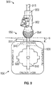
- FIG. 9 a side view of another example of an adjustable orthopedic system 900 including another alignment cube 930 and an alignment unit 950.
- the alignment cube 930 can be used to set relative guide plates between components of the alignment unit 950.
- the alignment unit 950 can include a guide plate 951 and an axis guide 952.
- the axis guide 952 can include a second guide wire bore 953.
- the alignment cube 930 can include a first guide wire bore 910.
- the guide wire bore 910 can be configured to receive a guide wire 915 (e.g., a rigid cylinder used for surgical procedures).
- the alignment cube 930 can include features similar to the alignment cube 830 or the alignment block 630.
- the guide wire 915 can extend orthogonally from a face 905 of the alignment cube 930.
- the alignment cube 930 can have one or more slots, such as a slot 920.
- the one or more slots can be configured to have one or more inclined planes, such as inclined plane 940.
- the guide plate 951 and the guide wire 915 can be mated with the alignment cube 930.
- the guide wire 915 extends orthogonally from the face 905 and through the guide wire bore (e.g., the guide wire bore 1020 of FIG. 10 ) of the guide plate 951.
- the guide plate 951 can be mated with the inclined plane 940 of a slot.
- the inclined plane 940 imparts an angle ⁇ to the guide plate 951 relative to the face 905.
- the relative angle ⁇ between the guide plate 951 and the face 905 can be the same as the relative angle between the guide plate 951 and the guide wire 915.
- the guide wire 915 can be able to extend through the guide plate 951 at an angle because the first guide wire bore (not shown) of the guide plate 951 can be configured to allow the guide wire 915 to translate through the guide plate 951 in one or more orientations.
- the guide plate 951 can be mated with the alignment cube 930 and the guide wire 915 can be mated with the alignment cube 930 and translated through the guide plate 951.
- the guide plate 951 has an angle relative to the alignment cube 930.
- the guide plate 951 has an angle (e.g., 1, 2, 5, 10, 15, 25, or 90 degrees) relative to the guide wire 915.
- the axis guide 952 can include the second guide wire bore 953.
- the second guide wire bore 953 can be configured to receive a guide wire (e.g., the guide wire 915) in a single orientation (e.g., the axis guide can be able to translate or slide along the guide wire).
- the reception of the guide wire by the axis guide 952 can make a longitudinal axis of the guide wire collinear with a longitudinal axis of the second guide wire bore 953.
- the axis guide 952 can include a head 954.
- the head 954 can be configured to mate with, or couple with, a socket (e.g., socket 1010 of FIG. 10 ) of the guide plate 951.
- the mating of the head 954 and the socket can allow for a fixable positioning of the axis guide 952 relative to the guide plate 951.
- the guide plate 951 can be mated with a slot of the alignment cube 930 and can be oriented at a first angle with respect to a face of the alignment cube 930.
- the relative angle between the axis guide 952 and the guide plate 951 can be the first angle when a guide cube can be used in combination with the guide plate 951 and the axis guide 952.
- the axis guide 952 can be translated along the guide wire 915 and brought into communication with the socket of the guide plate 951.
- the axis guide 952 can require a predetermined force (e.g., a surgeon applying a force, such as a hammer strike, to an end of the axis guide 952) to mate, or couple, the axis guide 952 with the guide plate 951.
- the positionable mating of the axis guide 952 and the guide plate 951 can allow for the position, or orientation, of the axis guide 952 relative to the guide plate 951 to remain temporarily fixed, or unchanged, once the position or orientation has been established or set, such as by a surgeon using a alignment cube 930. Because the axis guide was translated over the guide wire 915 and the guide wire 915 can be at the first angle relative to the guide plate, the positionable mating of the axis guide 952 with the guide plate 951 can set the relative angles between the axis guide 952 and the guide plate 951 at the first angle.
- the axis guide 952 and the guide plate 951 can have more than one relative angle set. In an example, the first angle can be in a first plane.
- the axis guide 952 and the guide plate 951 can be set at a second angle along a second plane.
- the first plane can be different than the second plane.
- the first plane can be orthogonal to the second plane. Additional relative angles and planes are capable of being used with the axis guide 952 and the guide plate 951.
- the mated (e.g., coupled) axis guide 952 and the guide plate 951 can be removed (e.g., decoupled) from the alignment cube 930 and the guide wire 915 as the alignment unit 950.
- the alignment unit 950 can maintain the relative angles between the axis guide 952 and the guide plate 951 that were set using the alignment cube 930.
- FIG. 10 is a posterior view of an example of the adjustable orthopedic system 900 of FIG. 9 showing the alignment unit 150 coupled with an anatomical feature 1000.
- the anatomical feature 1000 can be a scapula or a hip bone.
- the alignment unit 950 can include an axis guide 952 and a guide plate 951.
- the guide plate 951 can include a guide wire bore configured to allow a guide wire to translate through the guide wire bore in one or more orientations.
- the relative angles between the axis guide 952 and the guide plate 951 can remain fixed once they have been set, such as through the interaction of one or more surface features on a head 954 of the axis guide and a socket 1010 of the axis guide 120.
- the alignment unit 950 can be used to install a guide wire in a patient's anatomical feature (e.g., the anatomical feature 1000).
- the alignment unit 950 can allow for the guide wire to be installed at the relative angles that were established between the axis guide 952 and the guide plate 951.
- an individual e.g., a radiologist, a surgeon, a nurse, or the like
- x-ray images can be taken of the anatomical feature in various reference plan views (e.g., superior, anterior, medial, or the like).
- the anatomical geometry such as the angular relationship of the anatomical feature with respect to another anatomical feature or the reference plan views, can be determined by the individual from the x-rays.
- the individual can use the alignment cube 930 (or the alignment block 630 of FIG. 6 or the alignment cube 830 of FIG.
- the relative angles can be substantially similar (e.g., within 10 degrees) to the angular relationship determined from the x-rays.
- Use of x-rays and the alignment cube 930 can eliminate the need for more expensive forms of medical imaging.
- Use of x-rays and the alignment cube 930 can eliminate the need for fabricating a patient specific model of the anatomical feature. Fabrication of the patient specific model can be expensive.
- Geometric terms such as “parallel”, “perpendicular”, “round”, or “square”, are not intended to require absolute mathematical precision, unless the context indicates otherwise. Instead, such geometric terms allow for variations due to manufacturing or equivalent functions. For example, if an element is described as “round” or “generally round,” a component that is not precisely circular (e.g., one that is slightly oblong or is a many-sided polygon) is still encompassed by this description.
- Method examples described herein can be machine or computer-implemented at least in part. Some examples can include a computer-readable medium or machine-readable medium encoded with instructions operable to configure an electronic device to perform methods as described in the above examples.
- An implementation of such methods can include code, such as microcode, assembly language code, a higher-level language code, or the like. Such code can include computer readable instructions for performing various methods. The code may form portions of computer program products. Further, in an example, the code can be tangibly stored on one or more volatile, non-transitory, or nonvolatile tangible computer-readable media, such as during execution or at other times.
- Examples of these tangible computer-readable media can include, but are not limited to, hard disks, removable magnetic disks, removable optical disks (e.g., compact disks and digital video disks), magnetic cassettes, memory cards or sticks, random access memories (RAMs), read only memories (ROMs), and the like.
Landscapes
- Health & Medical Sciences (AREA)
- Life Sciences & Earth Sciences (AREA)
- Engineering & Computer Science (AREA)
- Surgery (AREA)
- General Health & Medical Sciences (AREA)
- Orthopedic Medicine & Surgery (AREA)
- Veterinary Medicine (AREA)
- Public Health (AREA)
- Biomedical Technology (AREA)
- Heart & Thoracic Surgery (AREA)
- Animal Behavior & Ethology (AREA)
- Medical Informatics (AREA)
- Molecular Biology (AREA)
- Nuclear Medicine, Radiotherapy & Molecular Imaging (AREA)
- Oral & Maxillofacial Surgery (AREA)
- Transplantation (AREA)
- Physical Education & Sports Medicine (AREA)
- Vascular Medicine (AREA)
- Cardiology (AREA)
- Dentistry (AREA)
- Physics & Mathematics (AREA)
- General Physics & Mathematics (AREA)
- Robotics (AREA)
- Mathematical Physics (AREA)
- Mathematical Optimization (AREA)
- Pure & Applied Mathematics (AREA)
- Business, Economics & Management (AREA)
- Educational Administration (AREA)
- Educational Technology (AREA)
- Theoretical Computer Science (AREA)
- Mathematical Analysis (AREA)
- Computational Mathematics (AREA)
- Algebra (AREA)
- Medicinal Chemistry (AREA)
- Chemical & Material Sciences (AREA)
- Prostheses (AREA)
Abstract
Description
- This application claims the benefit of
U.S. Provisional Patent Application Serial No. 62/488,499, filed on April 21, 2017 - One or more conditions (e.g., injury, bone spurs, arthritis, developmental disorder, or the like) can affect a joint (e.g., a shoulder or hip joint) and necessitate a medical procedure (e.g., total shoulder arthroplasty) to correct the one or more conditions. In an example, a surgeon conducting a total shoulder arthroplasty on a patient can place guide wires in the patient's anatomy to guide the surgeon in conducting the medical procedure.
- A problem to be solved can include the mal-alignment of replacement anatomy (e.g., a prosthetic device) during a medical procedure to install the replacement anatomy. Mal-alignment of replacement anatomy can be caused by a variety of factors (e.g., poor visibility of the anatomical feature undergoing the medical procedure, limited access to the anatomy, guesswork by a surgeon, or the like). In an example, a lack of ability to observe the anatomy undergoing a medical procedure can result in a mal-alignment of the replacement anatomy. Observation of the anatomy of the joint during the medical procedure can be hampered by the one or more conditions or by limited access to the joint itself (e.g., other anatomical features are blocking physical access to, or visual inspection of, the anatomy under observation).
- In an example, a diminished ability to observe the anatomical feature can make it difficult to determine how to install the replacement anatomy as it relates to the anatomical feature (e.g., establish a proper orientation and position between the anatomical feature and replacement anatomy). As discussed herein, a diminished ability to observe the anatomical feature can make it difficult to determine the angular relationships (e.g., relative angles) required to be established between the anatomical feature and the replacement anatomy. A diminished ability to observe the anatomical feature can require expensive, pre-operative, medical imaging (and other pre-operative tasks) to determine a desired orientation and position of the replacement anatomy in relation to the anatomical feature. In another example, even if the ability to observe the anatomical feature is not diminished, and the preferred orientation and position of the replacement anatomy in relation to the anatomical feature can be determined during a medical procedure to install the replacement anatomy. The preferred orientation and position of the replacement anatomy in relation to the anatomical feature can be determined during the medical procedure by the use of an angular indicator.
- In various embodiments of the systems and methods of the present application, an anatomy simulator, such as an alignment block having faces with variously angled sockets, can be used to facilitate alignment between medical device implant components and instrumentation components, intra-operatively or pre-operatively, as discussed below. Such an alignment block can preemptively alleviate negative effects that can be associated with mal-alignment of replacement anatomy.
- The mal-alignment of the replacement anatomy can have negative effects upon the efficacy of the medical procedure. Additionally, pre-operative tasks can include fabrication of instruments that are specific to the patient's anatomical feature. The patient-specific instruments can allow for an individual (e.g., a radiologist, a surgeon, a nurse, or the like) to facilitate accurate alignment of the replacement anatomy in relation to the anatomical feature. However, patient-specific instrument fabrication can be expensive, can require specialized equipment, such as computerized tomography scanners, or can take considerable time to fabricate the model. Further, because the instrument is patient-specific, the instrument cannot be re-used in a different medical procedure.
- In an example wherein a patient is undergoing a total shoulder arthroplasty procedure, the diminished ability to observe the anatomical feature of the shoulder joint can result in the mal-alignment, or improper installation, of replacement anatomy (e.g., a shoulder joint replacement apparatus). The mal-alignment of the replacement anatomy can negatively affect the durability or performance of the replacement anatomy. In an example, the mal-alignment of the replacement anatomy can cause a premature loosening of the replacement anatomy from the patient's anatomical feature or cause pain to the patient. A decrease in the durability or performance of the replacement anatomy can necessitate further medical procedures, or otherwise negatively affect the quality of life of the patient.
- A solution to the aforementioned problems to be solved can include an anatomy simulator. In an example, the anatomy simulator can be an alignment block or an alignment cube. The anatomy simulator can include a guide body having one or more faces. The anatomy simulator can include a first simulator socket. The first simulator socket can include a recess in a first face of the one or more faces. The first simulator socket can be configured to receive a first plate. The first simulator socket can include a first base portion, such as within the recess. The first base portion can be angled at a first angle with respect to the first face. The anatomy simulator can include a bore. The bore can extend from the base portion of the first simulator socket to the interior of the anatomy simulator. The bore can be configured to receive an alignment mechanism.
- The anatomy simulator can be used to set relative angles between the first plate and the alignment mechanism. The anatomy simulator can prevent the mal-alignment of replacement anatomy by ensuring a proper, or a desired, angular alignment between the first plate and the alignment mechanism.
- Aspect 1 can include or use subject matter (such as an apparatus, a system, a device, a method, a means for performing acts, or a device readable medium including instructions that, when performed by the device, can cause the device to perform acts), such as can include or use an anatomy simulator. The anatomy simulator can include a guide body having one or more faces. The anatomy simulator can include a first simulator socket forming a recess in a first face of the one or more faces. The first simulator socket can be configured to receive a first plate. The first simulator socket can include a first base portion. The anatomy simulator can include a bore extending from the base portion of the first simulator socket to an interior of the anatomy simulator. The bore can be configured to receive an alignment mechanism. The first base portion can be angled at a first angle with respect to the first face.
- Aspect 2 can include or use, or can optionally be combined with the subject matter of Aspect 1, to optionally include or use that the first plate and the alignment mechanism are configured to couple at one or more orientations and coupling the first plate with the alignment mechanism fixes the orientation of the first plate with respect to the alignment mechanism.
- Aspect 3 can include or use, or can optionally be combined with the subject matter of one or any combination of Aspects 1 or 2 to optionally include or use that the first simulator socket is configured to receive the first plate such that mating the first plate with the alignment mechanism and with the first base portion establishes the first angle between the first plate and the alignment mechanism.
- Aspect 4 can include or use, or can optionally be combined with the subject matter of one or any combination of Aspects 1 through 3 to optionally include or use that a portion of the alignment mechanism is quasi-spherical, and the quasi-spherical portion is configured to be received by a plate socket of the first plate.
- Aspect 5 can include or use, or can optionally be combined with the subject matter of one or any combination of Aspects 1 through 4 to optionally include or use that the quasi-spherical portion includes an expansion bore, wherein the expansion bore is configured to receive an expansion pin, the expansion pin expanding the quasi-spherical portion from a first diameter to a second diameter.
- Aspect 6 can include or use, or can optionally be combined with the subject matter of one or any combination of Aspects 1 through 5 to optionally include or use that expanding the quasi-spherical portion from a first diameter to a second diameter couples the first plate with the alignment mechanism and fixes the orientation of the first plate with respect to the alignment mechanism.
-
Aspect 7 can include or use, or can optionally be combined with the subject matter of one or any combination of Aspects 1 through 6 to optionally include or use that the first simulator socket is included in a plurality of simulator sockets and each of the one or more faces includes an individual simulator socket of the plurality of sockets. - Aspect 8 can include or use, or can optionally be combined with the subject matter of one or any combination of Aspects 1 through 7 to optionally include or use simulator indicia on the first face configured to provide alphanumerical information identifying the first angle.
- Aspect 9 can include or use, or can optionally be combined with the subject matter of one or any combination of Aspects 1 through 8 to optionally include or use that the first socket includes one or more indicator portions configured to be aligned with an alignment indicia of the first plate.
-
Aspect 10 can include or use, or can optionally be combined with the subject matter of one or any combination of Aspects 1 through 9 to optionally include or use that the bore is configured to extend orthogonally to the first face. - Aspect 11 can include or use, or can optionally be combined with the subject matter of one or any combination of Aspects 1 through 10 to optionally include or use that the alignment mechanism is a guide wire.
- Aspect 12 can include or use, or can optionally be combined with the subject matter of one or any combination of Aspects 1 through 11 to optionally include or use that the first face includes a first simulator indicia configured to provide alphanumerical information identifying the first angle. The first simulator socket can include a first indicator portion configured to receive an alignment indicia of the first plate. Aligning the alignment indicia with the first indicator portion and mating the first plate with the anatomy simulator can impart the first angle onto the first plate with respect to the first face.
- Aspect 13 can include or use, or can optionally be combined with the subject matter of one or any combination of Aspects 1 through 12 to optionally include or use the first plate. The first plate can include a first plate surface configured to couple with an anatomical feature of a patient. The first plate can include a second plate surface opposite the first plate surface. The first plate can include a plate socket extending into the first plate surface. The first plate can include a bore extending from the socket to the second guide plate surface to allow a guide wire to translate through the guide plate.
- Aspect 14 can include or use subject matter (such as an apparatus, a system, a device, a method, a means for performing acts, or a device readable medium including instructions that, when performed by the device, can cause the device to perform acts), such as can include or use a method for calibrating adjustable orthopaedic devices. The method can include identifying an anatomical geometry of an anatomical feature of the patient, wherein the geometry of the anatomical feature includes an anatomical axis and the anatomical geometry is at one or more angles with respect to the anatomical axis. The method can include coupling an alignment mechanism to an anatomy simulator, wherein the anatomy simulator is configured to reproduce the one or more angles with respect to the alignment mechanism. The method can include coupling a first plate with the anatomy simulator, wherein coupling the first plate with the anatomy simulator includes mating the first plate with a base portion of the anatomy simulator, wherein the mating of the first plate with the base portion establishes the first plate at the one or more angles with respect to the alignment mechanism.
- Aspect 15 can include or use, or can optionally be combined with the subject matter of Aspect 14, to optionally include or use coupling an axis guide to the first plate, wherein the alignment mechanism comprises a first guide wire and coupling the axis guide includes translating the first guide wire through an axis guide wire bore of the axis guide, the axis guide wire bore configured to receive the first guide wire in a single orientation.
- Aspect 16 can include or use, or can optionally be combined with the subject matter of one or any combination of Aspects 14 or 15 to optionally include or use decoupling the first plate and the axis guide as a unit from the anatomy simulator.
- Aspect 17 can include or use, or can optionally be combined with the subject matter of one or any combination of Aspects 14 through 16 to optionally include or use placing a guide wire in the anatomical feature of the patient, wherein the coupling of the axis guide with the guide plate allows the guide wire to be located at the anatomical axis of the anatomical feature.
- Aspect 18 can include or use, or can optionally be combined with the subject matter of one or any combination of Aspects 14 through 17 to optionally include or use mating the first plate with anatomy simulator includes mating the first plate with the alignment mechanism and establishing the first angle between the first plate and the alignment mechanism with the base portion of the anatomy simulator.
- Aspect 19 can include or use, or can optionally be combined with the subject matter of one or any combination of Aspects 14 through 18 to optionally include or use that the first plate and the alignment mechanism are configured to couple at one or more orientations and coupling the first plate with the alignment mechanism fixes the orientation of the first plate with respect to the alignment mechanism.
- Aspect 20 can include or use, or can optionally be combined with the subject matter of one or any combination of Aspects 14 through 19 to optionally include or use that a portion of the alignment mechanism is quasi-spherical, and the quasi-spherical portion is configured to be received by a plate socket of the first plate.
- Aspect 21 can include or use, or can optionally be combined with the subject matter of one or any combination of Aspects 14 through 20 to optionally include or use expanding an expansion bore of the quasi-spherical portion, wherein the expansion bore is configured to receive an expansion pin, the expansion pin expanding the quasi-spherical portion from a first diameter to a second diameter.
- Aspect 22 can include or use, or can optionally be combined with the subject matter of one or any combination of Aspects 14 through 21 to optionally include or use identifying an anatomical geometry of an anatomical feature of the patient includes determining the one or more angles of the anatomical geometry with respect to the anatomical axis.
- Each of these non-limiting examples can stand on its own, or can be combined in various permutations or combinations with one or more of the other examples.
- This overview is intended to provide an overview of subject matter of the present patent application. It is not intended to provide an exclusive or exhaustive explanation of the invention. The detailed description is included to provide further information about the present patent application.
- In the drawings, which are not necessarily drawn to scale, like numerals may describe similar components in different views. Like numerals having different letter suffixes may represent different instances of similar components. The drawings illustrate generally, by way of example, but not by way of limitation, various embodiments discussed in the present document.
-
FIG. 1 is a perspective view of an adjustable orthopedic system including a head, an adjuster, a stem, and a humerus. -
FIG. 2 is a perspective view of the adjuster ofFIG. 1 including an expansion pin, a dome, and a ball-taper. -
FIG. 3 is a cross-sectional view of the adjustable orthopedic system ofFIG. 1 . -
FIG. 4 is an anterior view of a humerus, and an angular indicator and a first angular identification card for use with the adjustable orthopedic system ofFIG. 1 . -
FIG. 5 is a superior view of the humerus and the angular indicator ofFIG. 4 and a second angular identification card for use with the adjustable orthopedic system ofFIG. 1 . -
FIG. 6 is a schematic view of an alignment block mated with the adjustor for use with the adjustable orthopedic system of claim 1. -
FIG. 7 is a top view of the alignment block ofFIG. 6 . -
FIG. 8 is a perspective view of an alignment cube for use with the adjustable orthopedic system ofFIG. 1 . -
FIG. 9 a side view of another example of an adjustable orthopedic system including another alignment cube and an alignment unit. -
FIG. 10 is a posterior view of an example of a adjustable orthopedic system ofFIG. 9 showing the alignment unit coupled with an anatomical feature. - As discussed herein, a diminished ability to observe an anatomical feature of a patient can make it difficult to determine intra-operatively how to install the adjustable orthopedic system 100 (
FIG. 1 ) as it relates to the anatomical feature, e.g., establish a proper orientation and position between the anatomical feature and replacement anatomy. The preferred orientation and position of the replacement anatomy (e.g., ahead 110, anadjuster 120 and a stem 130) in relation to the anatomy can be determined during the medical procedure by the use of an angular indicator (e.g., angular indicator 410 ofFIG. 4 orangular indicator 510 ofFIG. 5 ). - Also, a diminished ability to observe an anatomical feature of a patient can make it difficult to determine how to assemble and install the adjustable orthopedic system 900 (see
FIG. 9 ), e.g., establish a proper orientation between components of an instrumentation systems. The preferred orientation and position of components of the orthopedic system 900 (e.g.,guide plate 951 and the axis guide 952) can be determined pre-operatively using medical imaging. - An anatomical simulator (e.g., the
alignment block 630 ofFIGS. 6 and 7 , or thealignment cube 830 ofFIG. 8 ) can be used to intraoperatively to configure the relative angles between the anatomical feature and the replacement anatomy. The anatomical simulator can be used to set the relative angles of components of the replacement anatomy (e.g., between thehead 220 and theball taper 230 of theadjustor 120 ofFIGS. 1-3 ). - An anatomical simulator (e.g.,
alignment cube 930 ofFIG. 9 ) can be used to pre-operatively configure the relative angles between theguide plate 951 and theaxis guide 952 ofFIGS. 9 and10 . In an example, the anatomy simulator can be an alignment block (e.g., thealignment block 630 ofFIGS. 6 and 7 ) or an alignment cube (e.g., thealignment cube 830 ofFIG. 8 , or thealignment cube 930 ofFIG. 9 ). The anatomy simulator can include a guide body having one or more faces with angled sockets, as discussed below. The anatomy simulator, such as an alignment cube, can be used to set relative angles between various components. The anatomy simulator can prevent the mal-alignment of replacement anatomy or surgical instrumentation by ensuring a proper, or a preferred, angular alignment between components. -
FIG. 1 is a perspective view of an adjustableorthopedic system 100 including ahead 110, anadjuster 120, astem 130, and ahumerus 140. Thehead 110 can be configured to replicate a portion of an anatomical feature of a patient. Thehead 110 can have a circular cross section. Thehead 110 can have a round, or oval cross section. Thehead 110 can have a non-uniform cross section. Thehead 110 can replicate a portion of a humeral head. Thehead 110 can replicate a portion of a femoral head. In an example, a patient's humeral head is misshapen (e.g., due to injury, disease, malformation, or the like). As shown inFIG. 1 , a portion of the humeral head can be removed from a remaining portion of the humerus. Thehead 110 can be coupled to the remaining portion of the humerus. Thehead 110 can provide an improved surface for the humerus to mate with the scapula, such as by providing a smooth, consistent surface free from protrusions (e.g., malformations) or debris (e.g., bone spurs). - The
head 110 shown inFIG. 1 can be a provisional head used for determining the correct size and shape of ahead 110 to be permanently coupled with the anatomical feature. As previously discussed, a portion of the anatomical feature can be removed. The dimensions and orientation of the anatomical feature can vary from a first patient to a second patient. Use of the provisional head can allow for a medical practitioner to determine the correct configuration of thehead 110 to permanently couple with the anatomical feature of the patient. The provisional head can include indicia (e.g., markings) that indicate what type (e.g., circular or non-circular cross section) and/or size ofhead 110 can be permanently coupled to the anatomical feature. - The
head 110 can be coupled to theadjustor 120. Thehead 110 can be coupled to theadjustor 120 in one or more orientations. The coupling of thehead 110 to theadjustor 120 can be referred to as positionable mating of the head 119 with theadjustor 120. Positionable mating of thehead 110 with theadjustor 120 can also be referred to as fixable positioning. Fixable positioning of theadjustor 120 can include when the position, or orientation, of the components of theadjustor 120 remain fixed, or unchanged, once the position or orientation of those components has been established or set, such as by a surgeon. As discussed herein, fixable positioning can be achieved by an interference fit between the components of theadjustor 120. Theadjustor 120 can be configured to allow fixable positioning of theadjustor 120 components to allow for theadjustor 120 to adapt to variations in an anatomical feature of a patient. - As shown in
FIG. 1 , a portion of thehumerus 140 has been cut away and removed (e.g., thehumerus 140 has been resected). The angle of the cut can vary upon needs of a patient, such as by accounting for malformation or damage to the portion of thehumerus 140 being removed. The resected portion of thehumerus 140 can have aflat face 143. The fixable positioning of theadjustor 120 can allow for a wide range of angular relationships between thehead 110, thestem 130, and thehumerus 140 to be achieved. Stated another way, theadjustor 120 allows for non-patient-specific components (e.g., thehead 110 and the stem 130) to be configured into a patient-specific orientation or relationship with respect to thehumerus 140. Although thehumerus 140 is the anatomical feature under discussion, the devices and methods described herein can be used with various anatomies, such as hips, shoulders, and the like. - The
stem 130 can be configured to couple with thehumerus 140. Thestem 130 can couple with a medullary cavity of thehumerus 140. A cavity 145 (e.g., the medullary cavity) can be made in thehumerus 140. Thecavity 145 can be configured to receive thestem 130. Thecavity 145 can be located at the portion of thehumerus 140 that has been cut away and removed. Thecavity 145 can extend into the interior of thehumerus 140. Thestem 130 can have a rough exterior surface for increasing the coefficient of friction of the exterior surface, thereby improving the coupling of thestem 130 with thehumerus 140. Thestem 130 can be coupled to thehumerus 140 with an adhesive (e.g., glue, epoxy, cement, or the like). The volume of thecavity 145 surrounding thestem 130 can be filled with the adhesive. Coupling thestem 130 to thehumerus 140 with an adhesive can improve the strength and resiliency of the coupling of thestem 130 to thehumerus 140. Coupling thestem 130 with thehumerus 140 can allow for other structures, such as theadjuster 120, to be coupled to thestem 130 and thereby to thehumerus 140. Thestem 130 can have acoupler 135 configured to allow theadjustor 120 to couple and decouple from thestem 130. Theadjustor 120 can be configured to include an adjustor coupling feature that corresponds to thecoupler 130, such that theadjustor 120 can couple and decouple from thestem 130. -
FIG. 2 is a perspective view of theadjuster 120 ofFIG. 1 including anexpansion pin 210, adome 220, and a ball-taper 230. Thedome 220 can be configured to be orientated in a plurality of positions with respect to the ball-taper 230. Stated another way, thedome 220 has numerous degrees of freedom and can be positioned at a variety of angles with respect to the ball-taper 230. As discussed herein, theadjustor 120 can be configured to allow the fixable positioning of the components of theadjustor 120. Stated another way, theadjustor 120 can be configured to allow for the orientation of thedome 220 relative to the ball-taper 230 to be fixed once the orientation has been established. - The
dome 220 can be a first plate. Thedome 220 can include adome socket 260. Thedome socket 260 can be configured to receive ahead 240 of the ball-taper 230. Thedome socket 260 can be configured to positionably mate with thehead 240 of the ball-taper 230. In an example, thehead 240 of the ball-taper 230 can be quasi-spherical and thedome socket 260 can be sized and shaped such that thedome 220 is loosely coupled (e.g., able to freely be reoriented) with the ball-taper 230. - The ball-
taper 230 can be an alignment mechanism. The ball-taper 230 can include one ormore expansion slots 250. The one ormore expansion slots 250 can be configured to expand in response to an applied force. Expansion of the one ormore expansion slots 250 can change (e.g., increase or decrease) the dimensions of the ball-taper 230. Expansion of the one ormore expansion slots 250 can change the dimensions of thehead 240. Expansion of the one ormore expansion slots 250 can change thehead 240 from a first diameter to a second larger diameter. - The expansion of the one or
more expansion slots 250 can be achieved by allowing apetal 235 to deflect. Theadjustor 120 can include one or more petals. - The ball-
taper 230 can include anexpansion bore 270. The expansion bore 270 can be included in thehead 240. The expansion bore 270 can have a circular cross section. The expansion bore 270 can be tapered. The one ormore expansion slots 250 can extend from the exterior of the ball-taper 230 to theexpansion bore 270. The expansion bore 270 can be configured to receive theexpansion pin 210. The one or more petals can define theexpansion bore 270. - The
expansion pin 210 can be a cylinder with a constant diameter. Theexpansion pin 210 can include a cone portion (e.g., the diameter of theexpansion pin 210 changes linearly along a portion of a length of the expansion pin 210). Theexpansion pin 210 and expansion bore 270 can be configured such that when theexpansion pin 210 is translated into the expansion bore 270, the one or more petals deflect. The deflection of the one or more petals can cause theexpansion slots 270 to expand. The one ormore expansion slots 270 can expand outward (e.g., toward the exterior) from the ball-taper 230. - In an example, the
expansion pin 210 can be tapered and can be translated into theexpansion bore 270. As theexpansion pin 210 is translated into the expansion bore 270, a portion of theexpansion pin 210 engages with, and acts upon, theexpansion bore 270. The expansion bore 210 can be a smooth bore with a consistent diameter. The one ormore expansion slots 240 can allow for the diameter of the expansion bore 270 to change. - The one or
more expansion slots 240 can allow for the diameter of the expansion bore 270 to change as theexpansion pin 210 is translated within theexpansion bore 270. As theexpansion pin 210 is translated deeper into the expansion bore 270, the larger diameter portion of theexpansion pin 210 begins engaging with theexpansion bore 270. Continued translation of theexpansion pin 210 within the expansion bore 270 forces the diameter of the expansion bore 270 to increase and match the largest diameter portion of theexpansion pin 210 that is engaging with theexpansion bore 270. Expansion of the expansion bore 270 can be accomplished by tapering theexpansion pin 210, the expansion bore 270, or tapering both theexpansion pin 210 and theexpansion bore 270. Expansion of the expansion bore 270 can cause the one or more petals to deflect. Other configurations are possible for expanding the expansion bore 270, such as by using fasteners, electo-mechanical components, hydraulic components, or the like. - Expanding the expansion bore 270 can allow for the
dome 220 to positionably mate with the ball-taper 230. Postionable mating can occur through an interference fit between thedome 220 and the ball-taper 230. The expansion bore 270 can be expanded by theexpansion pin 220, thereby deflecting the one ormore expansion slots 240 outward. The outward deflection of theexpansion slots 240 changes the diameter of thehead 240 from a first diameter to a second diameter. Thedome socket 260 can be configured to have substantially the same shape as thehead 240 of the ball-taper 230. The dome socket can have the second diameter. Expanding the expansion bore 270 can force thehead 240 to engage with thedome socket 260. The expansion bore 270 can be expanded such that thedome 220 and the ball-taper 230 become positionably mated. Further translation of theexpansion pin 210 within the expansion bore 270 can generate greater frictional forces between thehead 220 and thedome socket 260, thereby tightening the coupling between thedome 220 and the ball-taper 230. Stated another way, translating theexpansion pin 210 deeper into the expansion bore 270 can increase an amount of force necessary to reorient thedome 220 with respect to the ball-taper 230. - Assembly of the
adjustor 120 can be accomplished by mating thedome 220 with the ball-taper 230. As described herein, the orientation of thedome 220 with respect to the ball-taper 230 can be established by using an alignment block (e.g., thealignment block 630 ofFIG. 6 ) or an alignment cube (e.g., thealignment cube FIGS. 8 or9 , respectively). The alignment block or alignment cube can establish the relative angles between thedome 220 and the ball-taper 230. Thedome 220 can include a through-hole configured to allow theexpansion pin 210 to translate through the through-hole. The through-hole in thedome 220 can be configured to allow theexpansion pin 210 to translate through thedome 220 and into the expansion bore 270 of the ball-taper 230. Theexpansion pin 210 can be inserted into the expansion bore 270 once the orientation of thedome 220 with respect to the ball-taper 230 has been established. As discussed herein, theexpansion pin 210 can fix the orientation of thedome 220 with respect to the ball-taper 230 by forcing thepetals 235 to push againstdome socket 260. -
FIG. 3 is a cross-sectional view of the adjustableorthopedic system 100 ofFIG. 1 . The adjustableorthopedic system 100 can include thehead 110, theadjustor 120, thestem 130, and thehumerus 140. Thehumerus 140 can include afirst axis 300A, asecond axis 300B, and athird axis 300C. Thefirst axis 300A,second axis 300B, and thethird axis 300C can be referred to collectively as theaxes first axis 300A and thesecond axis 300B can be offset at a first angle α. Thesecond axis 300B and thethird axis 300C can be offset at a second angle β. Thefirst axis 300A and thethird axis 300C can be offset at a third angle Θ. Thehumerus 140 can have a fourth axis (e.g., thefourth axis 500 ofFIG. 5 ). The fourth axis can extend orthogonally to the first andsecond axis - As discussed herein, a portion of an anatomical feature can be cut and removed (e.g., resected). As shown in
FIG. 3 ,axis 300C extends longitudinally through thehumerus 140. A portion of the humerus 140 (e.g., a portion of the head) has been resected. The resected portion of thehumerus 140 can have a flat face (e.g., theflat face 143 ofFIG. 1 ). Theaxis 300B can be collinear with the face of the resected portion. The face can be oriented at the angle α with respect to theaxis 300C. Theadjustor 120 can articulate to match the angle α. Stated another way, theadjustor 120 can be configured to be orientated at the angle α with respect to theaxis 300C. As shown inFIG. 3 , theaxis 300A can be a longitudinal axis of thestem 130. Thestem 130 can be orientated at the angle α such that thecoupler 135 is orthogonal to the face. In an example, thestem 130 is oriented at an angle different than α. Theadjustor 120 can be configured to couple with thestem 130 such that thehead 110 will be parallel (e.g., able to mate with substantially no gaps) to the flat face of thehumerus 140. Stated another way, theadjustor 120 can be configured to compensate for angular misalignment between thehead 110 and thestem 130. Theadjustor 120 can compensate for angular misalignment between thestem 130 and thehead 110 by articulating at the angle Θ. Theadjustor 120 can be configured to articulate in the direction of thesecond axis 300B. - As discussed herein, the
humerus 140 can have a fourth axis (e.g., thefourth axis 500 ofFIG. 5 ). The fourth axis can extend orthogonally to the first andsecond axis FIG. 3 . Theadjustor 120 can be configured to articulate in the direction of thefourth axis 500. Articulating in the direction of the fourth axis can compensate for angular misalignment between thestem 130 and thehead 110, such as when the flat face has a slope in the direction of the fourth axis. -
FIG. 4 is an anterior view of ahumerus 140, and anangular indicator 400 and a first angular identification card 410 for use with the adjustableorthopedic system 100 ofFIG. 1 . Theangular indicator 400 can include afirst finger 420, asecond finger 430, and abase plate 440. Thefirst finger 420 and thesecond finger 430 can extend orthogonally from thebase plate 440. The angular identification card 410 can be mated with a reference surface (e.g., thebase plate 440 or theface 143 ofFIG. 1 ). The angular identification card 410 can be located proximate to theangular indicator 400 such that an angular indicia, such as anangular indicia 450, to be seen between the first andsecond fingers - The
base plate 440 can include an indicator coupling feature configured to couple and decouple with a coupler (e.g., thecoupler 135 ofFIG. 1 ) of thestem 130, such that theangular indicator 400 can couple and decouple from thestem 130. The first andsecond fingers second fingers second fingers angular indicia 450 of the first angular identification card 410 to be seen between the first andsecond fingers - In an example, the first and
second fingers first axis 300A and thesecond axis 300B. Theangular indicia 450 can provide an indication of the angle Θ. The first andsecond fingers first axis 300A,second axis 300B,third axis 300C, or the fourth axis (e.g., thefourth axis 500 ofFIG. 5 ). The first andsecond fingers second fingers -
FIG. 5 is a superior view of thehumerus 140 and theangular indicator 400 ofFIG. 4 and a secondangular identification card 510 for use with the adjustableorthopedic system 100 ofFIG. 1 . Theangular indicator 400 can include thesecond finger 430 and athird finger 520. Inclusion of thethird finger 520 can allow for the angular relationship of multiple axis (e.g., thefirst axis 300A,second axis 300B,third axis 300C, or a fourth axis 500) to be determined without decoupling theangular indicator 400 from thestem 130. The second andthird fingers first axis 300A and thefourth axis 500 to be determined. -
FIG. 6 is a schematic view of analignment block 630 mated with the adjustor for use with the adjustableorthopedic system 100 of claim 1. Thealignment block 630 can be an anatomy simulator. Thealignment block 630 can include a body. Thealignment block 630 can be used to set relative angles between a dome (e.g., thedome 220 ofFIG. 1 ) and a ball taper (e.g., the ball-taper 230 ofFIG. 1 ). Thealignment block 630 can be used to set the angles α, β, Θ, and γ. In an example, thealignment block 630 can include aface 600, analignment bore 610, abase portion 620, one or more block indicia 640A, 640B, 640C, and 640D, aslot 650. - In an example, the
face 600 can include theslot 650. Theslot 650 can include thebase portion 620. Theslot 650 can be configured to receive the dome. Theslot 650 can be configured to receive the dome in a plurality of orientations. The reception of the dome by theslot 650 can mate the dome with thebase portion 620 of theslot 650. The alignment bore 610 can extend from theface 600 to another face located on the opposite side of thealignment block 630. The alignment bore 610 can be configured to receive a ball taper (not shown) in one or more orientations. As shown inFIG. 6 , the alignment bore 610 can be configured such that the ball taper can be received by the alignment bore 610 in four orientations. The alignment bore 610 can include afirst lobe 660A, asecond lobe 660B, athird lobe 660C, and afourth lobe 660D. Additional or fewer lobes can be included in thealignment bore 610. - In an example, the
base portion 620 of theslot 650 can be configured as an inclined plane. Stated another way, the bottom (e.g., the base portion 620) of theslot 650 can be angled at an angle µ (e.g., the angle µ ofFIG. 7 ) such that a first distance from a first side of theslot 650 to theface 600 can be different than a second distance from the bottom of a second side of theslot 650 to theface 600. Stated yet another way, the depth of theslot 650 relative to theface 600 can vary over the area of theslot 650. Thebase portion 620 of theslot 650 can be configured to include a plurality of inclined planes. The inclined plane can have an angular slope from a first end of the inclined plane to a second end of the inclined plane. The one or more block indicia 640A, 640B, 640C, and 640D can be used to identify the angular slope of the inclined plane. The one or more block indicia 640A, 640B, 640C, and 640D can respectively be aligned with the first, second, third, andfourth lobes -
FIG. 7 is a top view of the alignment block ofFIG. 6 . The ball-taper 230 can include lobes (not shown) configured to correspond with the first, second, third, andfourth lobes taper 230 can correspond with the first, second, third, andfourth lobes taper 230 is received by the alignment bore 610 in one of four orientations, although additional or fewer orientations are possible. The first, second, third, andfourth lobes taper 230 with respect to thealignment block 630. The ball-taper 230 can include an alignment indicia (not shown) used for maintaining the orientation of the ball taper. For example, the alignment indicia can be a colored portion of the ball-taper 230 that allows an individual to consistently orientate the ball-taper 230. The alignment indicia can be other markings on theball tapper 230 that allows for an individual to consistently orientate the ball-taper 230. The alignment indicia can be used to orientate the ball-taper 230 with respect to the stem 130 (shown inFIGS. 1 and3 ) such that the orientation imparted to theadjustor 120 can be transferred to the adjustableorthopedic system 100. - The alignment indicia (not shown) can be aligned with the
first lobe 660A. In an example, aligning the alignment indicia with thefirst lobe 660A and placing thealignment unit 120 within the slot 650 (e.g., mating thedome 220 with theslot 650, and the ball-taper 230 with the alignment bore 610) results in thedome 220 being angled at a 10 degree angle relative to theface 600 of the alignment block 630 (and the ball-taper 230). In another example, aligning the alignment indicia with thesecond lobe 660B and placing theadjustor 120 within theslot 650 results in thedome 220 being angled at a 10 degree angle relative to theface 600 of the alignment block 630 (and the ball-taper 230). However, by aligning the alignment indicia with thesecond lobe 660B instead of thefirst lobe 660A, the 10 degree angle relative to theface 600 will be reoriented into a different orientation with respect to the alignment block 630 (and the ball-taper 230). Stated another way, aligning the alignment indicia with thesecond lobe 660B instead of thefirst lobe 660A can allow for thedome 220 to be oriented at a 10 degree angle with respect to theface 600, but the direction of the tilt will differ depending upon the orientation of theadjustor 120 within theslot 650. Once the relative angles between thedome 220 and the ball-taper 230 have been established, the expansion pin 210 (shown inFIG. 2 ) can be driven into the expansion bore 270 (shown inFIG. 2 ), thereby temporarily fixing the position of thedome 220 with respect to the ball-taper 230. - In an example, the alignment indicia (not shown) can be positioned in the superior direction when the
adjustor 120 is coupled with the stem 130 (shown inFIGS 1 and3 ). Thebase portion 620 of thealignment block 630 can be at an angle with respect to theface 600. In the example ofFIG. 7 , thebase portion 620 can slope downward at a 10 degree angle (e.g., the angle µ is equal to 10 degrees) from left to right (e.g., the right side of thebase portion 620 will have a greater depth than the left side of the base portion 620). In an example, a medical practitioner is operating on a patient's left-side scapula. Placing theadjustor 120 within theslot 650 such that the alignment indicia (not shown) is aligned with thefirst lobe 660A, can result in thedome 220 having 10 degrees of retroversion tilt when coupled to the left-side scapula. However, if thedome 220 were coupled to a right-side scapula, thedome 220 would have 10 degrees of anteversion tilt. Furthermore, if theadjustor 120 were positioned so that the alignment indicia is aligned withthird lobe 660C, theadjustor 120 would be configured to provide 10 degrees retroversion tilt for a right shoulder. - Placing the
adjustor 120 within theslot 650 such that the alignment indicia is aligned with thesecond lobe 660B, can result in the dome 220 (with respect to the ball-taper 230) having 10 degrees of superior tilt when coupled to the left-side scapula. Placing theadjustor 120 within theslot 650 such that the alignment indicia is aligned with thefourth lobe 660D can result in thedome 220 having 10 degrees of inferior tilt (with respect to the ball-taper 230) when coupled to the left-side scapula. Because the inferior/superior relationship is unaffected by which side of the body an anatomical feature is located on, thedome 220 can have 10 degrees of inferior tilt or superior tilt when coupled to a right-side, or a left-side scapula when using fourth andsecond lobes - The positionable mating of the ball-
taper 230 and thedome 220 can allow for the position, or orientation, of the ball-taper 230 relative to thedome 220 to remain temporarily fixed, or unchanged, once the position or orientation has been established or set, such as by a surgeon using thealignment block 630. The ball-taper 230 and thedome 220 can have more than one relative angle set (e.g., the angles α, β, Θ, and γ). In an example, the angle α can be in a first plane. The ball-taper 230 and thedome 220 can be set at a second angle β along a second plane. The first plane can be different than the second plane. The first plane can be orthogonal to the second plane. Additional relative angles and planes are capable of being used with the ball-taper 230 and thedome 220. The mated (e.g., coupled) ball-taper 230 and thedome 220 can be removed (e.g., decoupled) from thealignment block 630 as theadjustor 120. Theadjustor 120 can maintain the relative angles between the ball-taper 230 and thedome 220 that were set using thealignment block 630. - An individual (e.g., a radiologist, a surgeon, a nurse, or the like) can determine the anatomical geometry of a patient by performing medical imaging on an anatomical feature of the patient. In an example, x-ray images can be taken of the anatomical feature in various reference plan views (e.g., superior, anterior, medial, or the like). The anatomical geometry, such as the angular relationship of the anatomical feature with respect to another anatomical feature or the reference plan views, can be determined by the individual from the x-rays. The individual can use the
alignment block 630 to establish the relative angles between thedome 220 and the ball-taper 230. The relative angles can be substantially similar (e.g., within 10 degrees) to the angular relationship determined from the x-rays. Use of x-rays and thealignment block 630 can eliminate the need for more expensive forms of medical imaging. Use of x-rays and thealignment block 630 can eliminate the need for fabricating a patient specific model of the anatomical feature. Fabrication of the patient specific model can be expensive. Additionally, thealignment block 630 can be included in a set of alignment blocks. The set of alignment blocks can provide a variety of combinations of superior, inferior, anteversion and retroversion settings. -
FIG. 8 is a perspective view of analignment cube 830 for use with the adjustableorthopedic system 100 ofFIG. 1 . Thealignment cube 830 can be an anatomy simulator. Thealignment cube 830 can be similar to thealignment block 630, such as including similar features, but providing additional configuration options. Thealignment cube 830 can include afirst face 800A, asecond face 800B, athird face 800C, a first alignment bore 810A, a second alignment bore 810B, a third alignment bore 810C, afirst slot 820A, asecond slot 820B, and a third slot 830C. Theface 600 ofFIGS. 6 and 7 can be one of six faces of thealignment cube 830. Stated another way, thefirst face 800A can be thealignment block 600 ofFIGS. 6 and 7 . - The
alignment cube 830 can provide additional combinations of superior, inferior, anteversion and retroversion settings than thealignment block 630. Thealignment cube 830 can have different combinations of superior, inferior, anteversion and retroversion settings than thealignment block 630. In an example, thefirst slot 820A can impart an angle to thedome 220 relative to thefirst face 800A. The angle can vary depending upon what face of thealignment cube 830 is used (e.g., the angle is 10 degrees for thefirst face 800A, but the angle for the other faces ofalignment cube 830, such as the second orthird face alignment cube 830, but the angle for other guide cubes will be greater than, or less than, 10 degrees). The angle for thealignment block 630 or thealignment cube 830 can vary in increments of 0.25 degrees, 0.5 degrees, 1 degree, 5 degrees, or 10 degrees, but other increments are possible. Thealignment block 630 and thealignment cube 830, or the set of alignment blocks or set of alignment cubes, can be used with a first patient and reused with subsequent patients after sanitizing. -
FIG. 9 a side view of another example of an adjustableorthopedic system 900 including anotheralignment cube 930 and analignment unit 950. Thealignment cube 930 can be used to set relative guide plates between components of thealignment unit 950. Thealignment unit 950 can include aguide plate 951 and anaxis guide 952. Theaxis guide 952 can include a second guide wire bore 953. - The
alignment cube 930 can include a first guide wire bore 910. The guide wire bore 910 can be configured to receive a guide wire 915 (e.g., a rigid cylinder used for surgical procedures). Thealignment cube 930 can include features similar to thealignment cube 830 or the alignment block 630.Theguide wire 915 can extend orthogonally from a face 905 of thealignment cube 930. Thealignment cube 930 can have one or more slots, such as aslot 920. The one or more slots can be configured to have one or more inclined planes, such asinclined plane 940. In an example, theguide plate 951 and theguide wire 915 can be mated with thealignment cube 930. Theguide wire 915 extends orthogonally from the face 905 and through the guide wire bore (e.g., the guide wire bore 1020 ofFIG. 10 ) of theguide plate 951. - The
guide plate 951 can be mated with theinclined plane 940 of a slot. Theinclined plane 940 imparts an angle Θ to theguide plate 951 relative to the face 905. The relative angle Θ between theguide plate 951 and the face 905 can be the same as the relative angle between theguide plate 951 and theguide wire 915. Theguide wire 915 can be able to extend through theguide plate 951 at an angle because the first guide wire bore (not shown) of theguide plate 951 can be configured to allow theguide wire 915 to translate through theguide plate 951 in one or more orientations. - In an example, the
guide plate 951 can be mated with thealignment cube 930 and theguide wire 915 can be mated with thealignment cube 930 and translated through theguide plate 951. Theguide plate 951 has an angle relative to thealignment cube 930. Theguide plate 951 has an angle (e.g., 1, 2, 5, 10, 15, 25, or 90 degrees) relative to theguide wire 915. - The
axis guide 952 can include the second guide wire bore 953. The second guide wire bore 953 can be configured to receive a guide wire (e.g., the guide wire 915) in a single orientation (e.g., the axis guide can be able to translate or slide along the guide wire). The reception of the guide wire by theaxis guide 952 can make a longitudinal axis of the guide wire collinear with a longitudinal axis of the second guide wire bore 953. - The
axis guide 952 can include ahead 954. Thehead 954 can be configured to mate with, or couple with, a socket (e.g.,socket 1010 ofFIG. 10 ) of theguide plate 951. The mating of thehead 954 and the socket can allow for a fixable positioning of theaxis guide 952 relative to theguide plate 951. In an example, theguide plate 951 can be mated with a slot of thealignment cube 930 and can be oriented at a first angle with respect to a face of thealignment cube 930. The relative angle between theaxis guide 952 and theguide plate 951 can be the first angle when a guide cube can be used in combination with theguide plate 951 and theaxis guide 952. Theaxis guide 952 can be translated along theguide wire 915 and brought into communication with the socket of theguide plate 951. Theaxis guide 952 can require a predetermined force (e.g., a surgeon applying a force, such as a hammer strike, to an end of the axis guide 952) to mate, or couple, theaxis guide 952 with theguide plate 951. - The positionable mating of the
axis guide 952 and theguide plate 951 can allow for the position, or orientation, of theaxis guide 952 relative to theguide plate 951 to remain temporarily fixed, or unchanged, once the position or orientation has been established or set, such as by a surgeon using aalignment cube 930. Because the axis guide was translated over theguide wire 915 and theguide wire 915 can be at the first angle relative to the guide plate, the positionable mating of theaxis guide 952 with theguide plate 951 can set the relative angles between theaxis guide 952 and theguide plate 951 at the first angle. Theaxis guide 952 and theguide plate 951 can have more than one relative angle set. In an example, the first angle can be in a first plane. Theaxis guide 952 and theguide plate 951 can be set at a second angle along a second plane. The first plane can be different than the second plane. The first plane can be orthogonal to the second plane. Additional relative angles and planes are capable of being used with theaxis guide 952 and theguide plate 951. The mated (e.g., coupled)axis guide 952 and theguide plate 951 can be removed (e.g., decoupled) from thealignment cube 930 and theguide wire 915 as thealignment unit 950. Thealignment unit 950 can maintain the relative angles between theaxis guide 952 and theguide plate 951 that were set using thealignment cube 930. -
FIG. 10 is a posterior view of an example of the adjustableorthopedic system 900 ofFIG. 9 showing the alignment unit 150 coupled with ananatomical feature 1000. Theanatomical feature 1000 can be a scapula or a hip bone. Thealignment unit 950 can include anaxis guide 952 and aguide plate 951. Theguide plate 951 can include a guide wire bore configured to allow a guide wire to translate through the guide wire bore in one or more orientations. The relative angles between theaxis guide 952 and theguide plate 951 can remain fixed once they have been set, such as through the interaction of one or more surface features on ahead 954 of the axis guide and asocket 1010 of theaxis guide 120. In an example, thealignment unit 950 can be used to install a guide wire in a patient's anatomical feature (e.g., the anatomical feature 1000). Thealignment unit 950 can allow for the guide wire to be installed at the relative angles that were established between theaxis guide 952 and theguide plate 951. - As previously discussed, an individual (e.g., a radiologist, a surgeon, a nurse, or the like) can determine the anatomical geometry of a patient by performing medical imaging on an anatomical feature of the patient. In an example, x-ray images can be taken of the anatomical feature in various reference plan views (e.g., superior, anterior, medial, or the like). The anatomical geometry, such as the angular relationship of the anatomical feature with respect to another anatomical feature or the reference plan views, can be determined by the individual from the x-rays. The individual can use the alignment cube 930 (or the
alignment block 630 ofFIG. 6 or thealignment cube 830 ofFIG. 8 ) to establish the relative angles between theguide plate 951 and theaxis guide 952. The relative angles can be substantially similar (e.g., within 10 degrees) to the angular relationship determined from the x-rays. Use of x-rays and thealignment cube 930 can eliminate the need for more expensive forms of medical imaging. Use of x-rays and thealignment cube 930 can eliminate the need for fabricating a patient specific model of the anatomical feature. Fabrication of the patient specific model can be expensive. - The above description includes references to the accompanying drawings, which form a part of the detailed description. The drawings show, by way of illustration, specific embodiments in which the invention can be practiced. These embodiments are also referred to herein as "examples." Such examples can include elements in addition to those shown or described. However, the present inventors also contemplate examples in which only those elements shown or described are provided. Moreover, the present inventors also contemplate examples using any combination or permutation of those elements shown or described (or one or more aspects thereof), either with respect to a particular example (or one or more aspects thereof), or with respect to other examples (or one or more aspects thereof) shown or described herein.
- In the event of inconsistent usages between this document and any documents so incorporated by reference, the usage in this document controls.
- In this document, the terms "a" or "an" are used, as is common in patent documents, to include one or more than one, independent of any other instances or usages of "at least one" or "one or more." In this document, the term "or" is used to refer to a nonexclusive or, such that "A or B" includes "A but not B," "B but not A," and "A and B," unless otherwise indicated. In this document, the terms "including" and "in which" are used as the plain-English equivalents of the respective terms "comprising" and "wherein." Also, in the following claims, the terms "including" and "comprising" are open-ended, that is, a system, device, article, composition, formulation, or process that includes elements in addition to those listed after such a term in a claim are still deemed to fall within the scope of that claim. Moreover, in the following claims, the terms "first," "second," and "third," etc. are used merely as labels, and are not intended to impose numerical requirements on their objects.
- Geometric terms, such as "parallel", "perpendicular", "round", or "square", are not intended to require absolute mathematical precision, unless the context indicates otherwise. Instead, such geometric terms allow for variations due to manufacturing or equivalent functions. For example, if an element is described as "round" or "generally round," a component that is not precisely circular (e.g., one that is slightly oblong or is a many-sided polygon) is still encompassed by this description.
- Method examples described herein can be machine or computer-implemented at least in part. Some examples can include a computer-readable medium or machine-readable medium encoded with instructions operable to configure an electronic device to perform methods as described in the above examples. An implementation of such methods can include code, such as microcode, assembly language code, a higher-level language code, or the like. Such code can include computer readable instructions for performing various methods. The code may form portions of computer program products. Further, in an example, the code can be tangibly stored on one or more volatile, non-transitory, or nonvolatile tangible computer-readable media, such as during execution or at other times. Examples of these tangible computer-readable media can include, but are not limited to, hard disks, removable magnetic disks, removable optical disks (e.g., compact disks and digital video disks), magnetic cassettes, memory cards or sticks, random access memories (RAMs), read only memories (ROMs), and the like.
- The above description is intended to be illustrative, and not restrictive. For example, the above-described examples (or one or more aspects thereof) may be used in combination with each other. Other embodiments can be used, such as by one of ordinary skill in the art upon reviewing the above description. The Abstract is provided to comply with 37 C.F.R. §1.72(b), to allow the reader to quickly ascertain the nature of the technical disclosure. It is submitted with the understanding that it will not be used to interpret or limit the scope or meaning of the claims. Also, in the above Detailed Description, various features may be grouped together to streamline the disclosure. This should not be interpreted as intending that an unclaimed disclosed feature is essential to any claim. Rather, inventive subject matter may lie in less than all features of a particular disclosed embodiment. Thus, the following claims are hereby incorporated into the Detailed Description as examples or embodiments, with each claim standing on its own as a separate embodiment, and it is contemplated that such embodiments can be combined with each other in various combinations or permutations. The scope of the invention should be determined with reference to the appended claims, along with the full scope of equivalents to which such claims are entitled.
Claims (22)
- An anatomy simulator, comprising:a guide body having one or more faces;a first simulator socket forming a recess in a first face of the one or more faces, wherein:the first simulator socket is configured to receive a first plate; andthe first simulator socket includes a first base portion; anda bore extending from the base portion of the first simulator socket to an interior of the anatomy simulator, wherein the bore is configured to receive an alignment mechanism;wherein the first base portion is angled at a first angle with respect to the first face.
- The anatomy simulator of claim 1, wherein the first plate and the alignment mechanism are configured to couple at one or more orientations and coupling the first plate with the alignment mechanism fixes the orientation of the first plate with respect to the alignment mechanism.
- The anatomy simulator of claim 1, wherein the first simulator socket is configured to receive the first plate such that mating the first plate with the alignment mechanism and with the first base portion establishes the first angle between the first plate and the alignment mechanism.
- The anatomy simulator of claim 3, wherein a portion of the alignment mechanism is quasi-spherical, and the quasi-spherical portion is configured to be received by a plate socket of the first plate.
- The anatomy simulator of claim 4, wherein the quasi-spherical portion includes an expansion bore, wherein the expansion bore is configured to receive an expansion pin, the expansion pin expanding the quasi-spherical portion from a first diameter to a second diameter.
- The anatomy simulator of claim 4, wherein expanding the quasi-spherical portion from a first diameter to a second diameter couples the first plate with the alignment mechanism and fixes the orientation of the first plate with respect to the alignment mechanism.
- The anatomy simulator of claim 1, wherein the first simulator socket is included in a plurality of simulator sockets and each of the one or more faces includes an individual simulator socket of the plurality of sockets.
- The anatomy simulator of claim 1, further comprising simulator indicia on the first face configured to provide alphanumerical information identifying the first angle.
- The anatomy simulator of claim 1, wherein the first socket includes one or more indicator portions configured to be aligned with an alignment indicia of the first plate.
- The anatomy simulator of claim 1, wherein the bore is configured to extend orthogonally to the first face.
- The anatomy simulator of claim 1, wherein the alignment mechanism is a guide wire.
- The anatomy simulator of claim 1, wherein:the first face includes a first simulator indicia configured to provide alphanumerical information identifying the first angle;the first simulator socket includes a first indicator portion configured to receive an alignment indicia of the first plate; andwherein aligning the alignment indicia with the first indicator portion and mating the first plate with the anatomy simulator imparts the first angle onto the first plate with respect to the first face.
- The anatomy simulator of claim 1, further comprising the first plate, the first plate comprising:a first plate surface configured to couple with an anatomical feature of a patient;a second plate surface opposite the first plate surface,a plate socket extending into the first plate surface; anda bore extending from the socket to the second guide plate surface to allow a guide wire to translate through the guide plate.
- A method for calibrating adjustable orthopaedic devices, comprising:identifying an anatomical geometry of an anatomical feature of the patient, wherein the geometry of the anatomical feature includes an anatomical axis and the anatomical geometry is at one or more angles with respect to the anatomical axis;coupling an alignment mechanism to an anatomy simulator, wherein the anatomy simulator is configured to reproduce the one or more angles with respect to the alignment mechanism; andcoupling a first plate with the anatomy simulator, wherein coupling the first plate with the anatomy simulator includes mating the first plate with a base portion of the anatomy simulator, wherein the mating of the first plate with the base portion establishes the first plate at the one or more angles with respect to the alignment mechanism.
- The method of claim 14, further comprising coupling an axis guide to the first plate, wherein the alignment mechanism comprises a first guide wire and coupling the axis guide includes translating the first guide wire through an axis guide wire bore of the axis guide, the axis guide wire bore configured to receive the first guide wire in a single orientation.
- The method of claim 15, further comprising decoupling the first plate and the axis guide as a unit from the anatomy simulator.
- The method of claim 16, further comprising placing a guide wire in the anatomical feature of the patient, wherein the coupling of the axis guide with the guide plate allows the guide wire to be located at the anatomical axis of the anatomical feature.
- The method of claim 14, wherein mating the first plate with anatomy simulator includes mating the first plate with the alignment mechanism and establishing the first angle between the first plate and the alignment mechanism with the base portion of the anatomy simulator.
- The method of claim 18, wherein the first plate and the alignment mechanism are configured to couple at one or more orientations and coupling the first plate with the alignment mechanism fixes the orientation of the first plate with respect to the alignment mechanism.
- The method of claim 19, wherein a portion of the alignment mechanism is quasi-spherical, and the quasi-spherical portion is configured to be received by a plate socket of the first plate.
- The method of claim 20, further comprising expanding an expansion bore of the quasi-spherical portion, wherein the expansion bore is configured to receive an expansion pin, the expansion pin expanding the quasi-spherical portion from a first diameter to a second diameter.
- The method of claim 14, wherein identifying an anatomical geometry of an anatomical feature of the patient includes determining the one or more angles of the anatomical geometry with respect to the anatomical axis.
Applications Claiming Priority (1)
| Application Number | Priority Date | Filing Date | Title |
|---|---|---|---|
| US201762488499P | 2017-04-21 | 2017-04-21 |
Publications (2)
| Publication Number | Publication Date |
|---|---|
| EP3453363A1 true EP3453363A1 (en) | 2019-03-13 |
| EP3453363B1 EP3453363B1 (en) | 2020-08-05 |
Family
ID=62044538
Family Applications (1)
| Application Number | Title | Priority Date | Filing Date |
|---|---|---|---|
| EP18168424.2A Active EP3453363B1 (en) | 2017-04-21 | 2018-04-20 | Tool for fixed customised relative alignment of adjustable orthopedic devices |
Country Status (2)
| Country | Link |
|---|---|
| US (2) | US10849690B2 (en) |
| EP (1) | EP3453363B1 (en) |
Families Citing this family (7)
| Publication number | Priority date | Publication date | Assignee | Title |
|---|---|---|---|---|
| CN105939682B (en) | 2013-12-02 | 2019-06-21 | 捷迈有限公司 | Adjustable Orthopedic Connector |
| EP4282383B1 (en) | 2017-01-09 | 2026-05-06 | Zimmer, Inc. | Adjustable orthopedic connections |
| GB201705917D0 (en) | 2017-04-12 | 2017-05-24 | Davidson Craig | Femoral trialling kit and assembly |
| US10849690B2 (en) | 2017-04-21 | 2020-12-01 | Zimmer, Inc. | Tool for fixed customised relative alignment of adjustable orthopedic devices |
| US10925658B2 (en) | 2017-04-21 | 2021-02-23 | Zimmer, Inc. | Guide wire alignment |
| GB201716107D0 (en) * | 2017-10-03 | 2017-11-15 | Depuy Ireland Ultd Co | Trial neck apparatus and method |
| US10813769B2 (en) * | 2018-07-24 | 2020-10-27 | DePuy Synthes Products, Inc. | Baseplate of a modular shoulder joint prosthesis and related methods for implanting the same |
Citations (4)
| Publication number | Priority date | Publication date | Assignee | Title |
|---|---|---|---|---|
| WO2001082843A2 (en) * | 2000-05-03 | 2001-11-08 | Smith & Nephew, Inc. | Multi modular trialing system and instrumentation |
| US20040064190A1 (en) * | 2002-09-30 | 2004-04-01 | Ball Robert J. | Reverse-type humeral prosthesis |
| US20090192621A1 (en) * | 2003-10-08 | 2009-07-30 | Biomet Manufacturing Corp. | Shoulder Implant Assembly |
| US8052758B1 (en) * | 2005-03-09 | 2011-11-08 | Biomet Manufacturing Corp. | Method and apparatus for trialing a modular humeral head |
Family Cites Families (44)
| Publication number | Priority date | Publication date | Assignee | Title |
|---|---|---|---|---|
| US6517583B1 (en) | 2000-01-30 | 2003-02-11 | Diamicron, Inc. | Prosthetic hip joint having a polycrystalline diamond compact articulation surface and a counter bearing surface |
| FR2727857B1 (en) | 1994-12-08 | 1997-01-24 | Cedior | TOTAL SHOULDER PROSTHESIS |
| US6045581A (en) | 1997-12-12 | 2000-04-04 | Sulzer Orthopedics Inc. | Implantable prosthesis having textured bearing surfaces |
| US6827740B1 (en) | 1999-12-08 | 2004-12-07 | Gary K. Michelson | Spinal implant surface configuration |
| AU2001285071A1 (en) | 2000-08-17 | 2002-02-25 | John David | Trajectory guide with instrument immobilizer |
| DE10123517C1 (en) | 2001-05-15 | 2002-11-28 | Keramed Medizintechnik Gmbh | Shoulder endoprosthesis has a joint connection formed by a protrusion on a middle part clamped by a clamping element from the proximal end of the middle part in a recess in the proximal end of a shaft |
| US6942699B2 (en) | 2001-07-11 | 2005-09-13 | Biomet, Inc. | Shoulder prosthesis |
| US8317871B2 (en) | 2001-07-27 | 2012-11-27 | Biomet Manufacturing Corp. | Modular humeral head resurfacing system |
| US6676705B1 (en) | 2001-09-13 | 2004-01-13 | Eugene M. Wolf | Variable tilt angle taper lock shoulder prosthesis |
| EP1321114B1 (en) | 2001-11-21 | 2018-03-07 | Zimmer GmbH | Shoulder prothesis |
| AU2002353484A1 (en) | 2001-12-04 | 2003-06-17 | Discure Ltd. | Cushion bearing implants for load bearing applications |
| US7097663B1 (en) | 2001-12-17 | 2006-08-29 | Smith & Nephew, Inc. | Modular prosthesis system with novel locking mechanism |
| CN100574728C (en) | 2002-03-30 | 2009-12-30 | 无限整形外科有限公司 | Intervertebral disc replacement device and system |
| US6736851B2 (en) | 2002-06-28 | 2004-05-18 | Depuy Orthopaedics, Inc. | Modular shoulder prosthesis |
| US7175663B1 (en) | 2003-10-08 | 2007-02-13 | Biomet Manufacturing Corp. | Shoulder implant assembly |
| US6986790B2 (en) | 2002-09-30 | 2006-01-17 | Depuy Products, Inc. | Shoulder prosthesis having infinitely adjustable humeral head |
| US7048739B2 (en) | 2002-12-31 | 2006-05-23 | Depuy Spine, Inc. | Bone plate and resilient screw system allowing bi-directional assembly |
| US7887544B2 (en) | 2003-03-10 | 2011-02-15 | Tornier Sas | Ancillary tool for positioning a glenoid implant |
| US7615080B2 (en) | 2003-06-30 | 2009-11-10 | Depuy Products, Inc. | Joint prosthesis having infinitely adjustable head |
| US7241314B1 (en) | 2004-09-16 | 2007-07-10 | Biomet Manufacturing Corp. | Reverse shoulder prosthesis |
| EP1903996A2 (en) | 2005-07-06 | 2008-04-02 | Copf jun., Franz | Intervertebral disc prosthesis |
| DE202005020876U1 (en) | 2005-11-16 | 2006-10-05 | Plus Orthopedics Ag | Endoprosthesis comprises a shaft, which extends along a primary axis, a distal end piece and a proximal end piece |
| DE102006002211B4 (en) | 2006-01-16 | 2007-09-27 | Dot Gmbh | Polyaxial alignable stabilizing element for endoprostheses |
| US7753959B2 (en) | 2006-03-20 | 2010-07-13 | Biomet Manufacturing Corp. | Modular center pegged glenoid |
| JP5180953B2 (en) | 2006-03-23 | 2013-04-10 | イグザクテック・インコーポレイテッド | Reverse shoulder glenoid plate and prosthesis |
| FR2909859B1 (en) | 2006-12-13 | 2011-02-11 | Lionel Francois Simon | JOINT PROSTHESIS OF INTERVERTEBRAL DISC |
| US7572294B2 (en) | 2007-03-07 | 2009-08-11 | Biomet Manufacturing Corp. | Method and apparatus for removing an acetabular bearing |
| US8055886B2 (en) | 2007-07-12 | 2011-11-08 | Texas Instruments Incorporated | Processor micro-architecture for compute, save or restore multiple registers and responsive to first instruction for repeated issue of second instruction |
| US8002838B2 (en) | 2008-06-11 | 2011-08-23 | Depuy Products, Inc. | Joint prosthesis with positionable head |
| US8702717B2 (en) | 2009-07-31 | 2014-04-22 | Zimmer Gmbh | Glenoid alignment tool |
| US20110106267A1 (en) | 2009-10-30 | 2011-05-05 | Depuy Products, Inc. | Shoulder prosthesis adjustable humeral head mechanism |
| US8246687B2 (en) | 2009-11-18 | 2012-08-21 | Biomet Manufacturing Corp. | Shoulder prosthetic |
| US20110196430A1 (en) | 2010-02-10 | 2011-08-11 | Walsh David A | Spinal fixation assembly with intermediate element |
| US8808335B2 (en) | 2010-03-08 | 2014-08-19 | Miami Device Solutions, Llc | Locking element for a polyaxial bone anchor, bone plate assembly and tool |
| WO2012024665A2 (en) | 2010-08-20 | 2012-02-23 | K2M, Inc. | Spinal fixation system |
| EP2614787B1 (en) | 2012-01-16 | 2017-03-15 | Carbofix Orthopedics Ltd. | Multi-axial bone plate fixation |
| US9033990B2 (en) | 2012-04-10 | 2015-05-19 | The Cleveland Clinic Foundation | Directed structure placement guide |
| US9387022B2 (en) | 2012-06-27 | 2016-07-12 | DePuy Synthes Products, Inc. | Variable angle bone fixation device |
| CN105939682B (en) | 2013-12-02 | 2019-06-21 | 捷迈有限公司 | Adjustable Orthopedic Connector |
| US9826994B2 (en) | 2014-09-29 | 2017-11-28 | Biomet Manufacturing, Llc | Adjustable glenoid pin insertion guide |
| IL244461A (en) | 2016-03-06 | 2017-06-29 | Jacobsen Hagay | Adaptor for adjustably mounting a structure onto a biological base |
| EP4282383B1 (en) | 2017-01-09 | 2026-05-06 | Zimmer, Inc. | Adjustable orthopedic connections |
| US10925658B2 (en) | 2017-04-21 | 2021-02-23 | Zimmer, Inc. | Guide wire alignment |
| US10849690B2 (en) | 2017-04-21 | 2020-12-01 | Zimmer, Inc. | Tool for fixed customised relative alignment of adjustable orthopedic devices |
-
2018
- 2018-04-18 US US15/956,502 patent/US10849690B2/en active Active
- 2018-04-20 EP EP18168424.2A patent/EP3453363B1/en active Active
-
2020
- 2020-10-28 US US17/082,812 patent/US11730542B2/en active Active
Patent Citations (4)
| Publication number | Priority date | Publication date | Assignee | Title |
|---|---|---|---|---|
| WO2001082843A2 (en) * | 2000-05-03 | 2001-11-08 | Smith & Nephew, Inc. | Multi modular trialing system and instrumentation |
| US20040064190A1 (en) * | 2002-09-30 | 2004-04-01 | Ball Robert J. | Reverse-type humeral prosthesis |
| US20090192621A1 (en) * | 2003-10-08 | 2009-07-30 | Biomet Manufacturing Corp. | Shoulder Implant Assembly |
| US8052758B1 (en) * | 2005-03-09 | 2011-11-08 | Biomet Manufacturing Corp. | Method and apparatus for trialing a modular humeral head |
Also Published As
| Publication number | Publication date |
|---|---|
| EP3453363B1 (en) | 2020-08-05 |
| US11730542B2 (en) | 2023-08-22 |
| US10849690B2 (en) | 2020-12-01 |
| US20180303551A1 (en) | 2018-10-25 |
| US20210068901A1 (en) | 2021-03-11 |
Similar Documents
| Publication | Publication Date | Title |
|---|---|---|
| US11730542B2 (en) | Tool for fixed customised relative alignment of adjustable orthopedic devices | |
| EP3459471B1 (en) | Guide wire alignment | |
| US9848929B2 (en) | Devices and method of achieving bone fusion | |
| US10130428B2 (en) | System and methods for positioning bone cut guide | |
| US8052758B1 (en) | Method and apparatus for trialing a modular humeral head | |
| CN105307599B (en) | Cotyloid implant alignment device and method | |
| CN100407990C (en) | Metrology instrument for surgical procedures | |
| EP3278746B1 (en) | Centering guide system for arthroplasty | |
| US10034677B2 (en) | Customizable joint replacement apparatus | |
| US20050049602A1 (en) | Surgical instruments | |
| CA2601601A1 (en) | Medical securing member placement system | |
| JP2022153485A (en) | Gap gauge and unit that can check the flexion interval before cutting the posterior femur | |
| EP3284442A2 (en) | Stabilized drill guide | |
| KR101096381B1 (en) | Mechanisms for insertion of intervertebral prostheses | |
| US9572687B2 (en) | Native version alignment devices and methods | |
| US20230277334A1 (en) | Hip Stem Alignment Guide | |
| US20240216145A1 (en) | Implants, instruments, systems, and methods of using | |
| US20220079778A1 (en) | Systems and Methods for Selecting Artificial Femoral Components | |
| AU2004296536A1 (en) | Instrument Set for Inserting an Intervertebral Joint Prosthesis | |
| HK1098322B (en) | A gauge for use in a surgical procedure | |
| HK1128220A (en) | A gauge for use in a surgical procedure |
Legal Events
| Date | Code | Title | Description |
|---|---|---|---|
| PUAI | Public reference made under article 153(3) epc to a published international application that has entered the european phase |
Free format text: ORIGINAL CODE: 0009012 |
|
| STAA | Information on the status of an ep patent application or granted ep patent |
Free format text: STATUS: THE APPLICATION HAS BEEN PUBLISHED |
|
| AK | Designated contracting states |
Kind code of ref document: A1 Designated state(s): AL AT BE BG CH CY CZ DE DK EE ES FI FR GB GR HR HU IE IS IT LI LT LU LV MC MK MT NL NO PL PT RO RS SE SI SK SM TR |
|
| AX | Request for extension of the european patent |
Extension state: BA ME |
|
| STAA | Information on the status of an ep patent application or granted ep patent |
Free format text: STATUS: REQUEST FOR EXAMINATION WAS MADE |
|
| 17P | Request for examination filed |
Effective date: 20190913 |
|
| RBV | Designated contracting states (corrected) |
Designated state(s): AL AT BE BG CH CY CZ DE DK EE ES FI FR GB GR HR HU IE IS IT LI LT LU LV MC MK MT NL NO PL PT RO RS SE SI SK SM TR |
|
| GRAP | Despatch of communication of intention to grant a patent |
Free format text: ORIGINAL CODE: EPIDOSNIGR1 |
|
| STAA | Information on the status of an ep patent application or granted ep patent |
Free format text: STATUS: GRANT OF PATENT IS INTENDED |
|
| INTG | Intention to grant announced |
Effective date: 20200217 |
|
| GRAS | Grant fee paid |
Free format text: ORIGINAL CODE: EPIDOSNIGR3 |
|
| GRAA | (expected) grant |
Free format text: ORIGINAL CODE: 0009210 |
|
| STAA | Information on the status of an ep patent application or granted ep patent |
Free format text: STATUS: THE PATENT HAS BEEN GRANTED |
|
| AK | Designated contracting states |
Kind code of ref document: B1 Designated state(s): AL AT BE BG CH CY CZ DE DK EE ES FI FR GB GR HR HU IE IS IT LI LT LU LV MC MK MT NL NO PL PT RO RS SE SI SK SM TR |
|
| REG | Reference to a national code |
Ref country code: GB Ref legal event code: FG4D |
|
| REG | Reference to a national code |
Ref country code: CH Ref legal event code: EP Ref country code: CH Ref legal event code: NV Representative=s name: MICHELI AND CIE SA, CH |
|
| REG | Reference to a national code |
Ref country code: AT Ref legal event code: REF Ref document number: 1297663 Country of ref document: AT Kind code of ref document: T Effective date: 20200815 |
|
| REG | Reference to a national code |
Ref country code: DE Ref legal event code: R096 Ref document number: 602018006554 Country of ref document: DE |
|
| REG | Reference to a national code |
Ref country code: IE Ref legal event code: FG4D |
|
| REG | Reference to a national code |
Ref country code: DE Ref legal event code: R082 Ref document number: 602018006554 Country of ref document: DE Representative=s name: VENNER SHIPLEY GERMANY LLP, DE Ref country code: DE Ref legal event code: R082 Ref document number: 602018006554 Country of ref document: DE Representative=s name: VENNER SHIPLEY LLP, DE |
|
| REG | Reference to a national code |
Ref country code: LT Ref legal event code: MG4D |
|
| REG | Reference to a national code |
Ref country code: NL Ref legal event code: MP Effective date: 20200805 |
|
| REG | Reference to a national code |
Ref country code: AT Ref legal event code: MK05 Ref document number: 1297663 Country of ref document: AT Kind code of ref document: T Effective date: 20200805 |
|
| PG25 | Lapsed in a contracting state [announced via postgrant information from national office to epo] |
Ref country code: LT Free format text: LAPSE BECAUSE OF FAILURE TO SUBMIT A TRANSLATION OF THE DESCRIPTION OR TO PAY THE FEE WITHIN THE PRESCRIBED TIME-LIMIT Effective date: 20200805 Ref country code: FI Free format text: LAPSE BECAUSE OF FAILURE TO SUBMIT A TRANSLATION OF THE DESCRIPTION OR TO PAY THE FEE WITHIN THE PRESCRIBED TIME-LIMIT Effective date: 20200805 Ref country code: AT Free format text: LAPSE BECAUSE OF FAILURE TO SUBMIT A TRANSLATION OF THE DESCRIPTION OR TO PAY THE FEE WITHIN THE PRESCRIBED TIME-LIMIT Effective date: 20200805 Ref country code: GR Free format text: LAPSE BECAUSE OF FAILURE TO SUBMIT A TRANSLATION OF THE DESCRIPTION OR TO PAY THE FEE WITHIN THE PRESCRIBED TIME-LIMIT Effective date: 20201106 Ref country code: ES Free format text: LAPSE BECAUSE OF FAILURE TO SUBMIT A TRANSLATION OF THE DESCRIPTION OR TO PAY THE FEE WITHIN THE PRESCRIBED TIME-LIMIT Effective date: 20200805 Ref country code: NO Free format text: LAPSE BECAUSE OF FAILURE TO SUBMIT A TRANSLATION OF THE DESCRIPTION OR TO PAY THE FEE WITHIN THE PRESCRIBED TIME-LIMIT Effective date: 20201105 Ref country code: SE Free format text: LAPSE BECAUSE OF FAILURE TO SUBMIT A TRANSLATION OF THE DESCRIPTION OR TO PAY THE FEE WITHIN THE PRESCRIBED TIME-LIMIT Effective date: 20200805 Ref country code: BG Free format text: LAPSE BECAUSE OF FAILURE TO SUBMIT A TRANSLATION OF THE DESCRIPTION OR TO PAY THE FEE WITHIN THE PRESCRIBED TIME-LIMIT Effective date: 20201105 Ref country code: HR Free format text: LAPSE BECAUSE OF FAILURE TO SUBMIT A TRANSLATION OF THE DESCRIPTION OR TO PAY THE FEE WITHIN THE PRESCRIBED TIME-LIMIT Effective date: 20200805 Ref country code: PT Free format text: LAPSE BECAUSE OF FAILURE TO SUBMIT A TRANSLATION OF THE DESCRIPTION OR TO PAY THE FEE WITHIN THE PRESCRIBED TIME-LIMIT Effective date: 20201207 |
|
| PG25 | Lapsed in a contracting state [announced via postgrant information from national office to epo] |
Ref country code: PL Free format text: LAPSE BECAUSE OF FAILURE TO SUBMIT A TRANSLATION OF THE DESCRIPTION OR TO PAY THE FEE WITHIN THE PRESCRIBED TIME-LIMIT Effective date: 20200805 Ref country code: RS Free format text: LAPSE BECAUSE OF FAILURE TO SUBMIT A TRANSLATION OF THE DESCRIPTION OR TO PAY THE FEE WITHIN THE PRESCRIBED TIME-LIMIT Effective date: 20200805 Ref country code: LV Free format text: LAPSE BECAUSE OF FAILURE TO SUBMIT A TRANSLATION OF THE DESCRIPTION OR TO PAY THE FEE WITHIN THE PRESCRIBED TIME-LIMIT Effective date: 20200805 Ref country code: NL Free format text: LAPSE BECAUSE OF FAILURE TO SUBMIT A TRANSLATION OF THE DESCRIPTION OR TO PAY THE FEE WITHIN THE PRESCRIBED TIME-LIMIT Effective date: 20200805 Ref country code: IS Free format text: LAPSE BECAUSE OF FAILURE TO SUBMIT A TRANSLATION OF THE DESCRIPTION OR TO PAY THE FEE WITHIN THE PRESCRIBED TIME-LIMIT Effective date: 20201205 |
|
| PG25 | Lapsed in a contracting state [announced via postgrant information from national office to epo] |
Ref country code: CZ Free format text: LAPSE BECAUSE OF FAILURE TO SUBMIT A TRANSLATION OF THE DESCRIPTION OR TO PAY THE FEE WITHIN THE PRESCRIBED TIME-LIMIT Effective date: 20200805 Ref country code: DK Free format text: LAPSE BECAUSE OF FAILURE TO SUBMIT A TRANSLATION OF THE DESCRIPTION OR TO PAY THE FEE WITHIN THE PRESCRIBED TIME-LIMIT Effective date: 20200805 Ref country code: RO Free format text: LAPSE BECAUSE OF FAILURE TO SUBMIT A TRANSLATION OF THE DESCRIPTION OR TO PAY THE FEE WITHIN THE PRESCRIBED TIME-LIMIT Effective date: 20200805 Ref country code: EE Free format text: LAPSE BECAUSE OF FAILURE TO SUBMIT A TRANSLATION OF THE DESCRIPTION OR TO PAY THE FEE WITHIN THE PRESCRIBED TIME-LIMIT Effective date: 20200805 Ref country code: SM Free format text: LAPSE BECAUSE OF FAILURE TO SUBMIT A TRANSLATION OF THE DESCRIPTION OR TO PAY THE FEE WITHIN THE PRESCRIBED TIME-LIMIT Effective date: 20200805 |
|
| REG | Reference to a national code |
Ref country code: DE Ref legal event code: R097 Ref document number: 602018006554 Country of ref document: DE |
|
| PG25 | Lapsed in a contracting state [announced via postgrant information from national office to epo] |
Ref country code: AL Free format text: LAPSE BECAUSE OF FAILURE TO SUBMIT A TRANSLATION OF THE DESCRIPTION OR TO PAY THE FEE WITHIN THE PRESCRIBED TIME-LIMIT Effective date: 20200805 |
|
| PLBE | No opposition filed within time limit |
Free format text: ORIGINAL CODE: 0009261 |
|
| STAA | Information on the status of an ep patent application or granted ep patent |
Free format text: STATUS: NO OPPOSITION FILED WITHIN TIME LIMIT |
|
| PG25 | Lapsed in a contracting state [announced via postgrant information from national office to epo] |
Ref country code: SK Free format text: LAPSE BECAUSE OF FAILURE TO SUBMIT A TRANSLATION OF THE DESCRIPTION OR TO PAY THE FEE WITHIN THE PRESCRIBED TIME-LIMIT Effective date: 20200805 |
|
| 26N | No opposition filed |
Effective date: 20210507 |
|
| PG25 | Lapsed in a contracting state [announced via postgrant information from national office to epo] |
Ref country code: IT Free format text: LAPSE BECAUSE OF FAILURE TO SUBMIT A TRANSLATION OF THE DESCRIPTION OR TO PAY THE FEE WITHIN THE PRESCRIBED TIME-LIMIT Effective date: 20200805 |
|
| PG25 | Lapsed in a contracting state [announced via postgrant information from national office to epo] |
Ref country code: SI Free format text: LAPSE BECAUSE OF FAILURE TO SUBMIT A TRANSLATION OF THE DESCRIPTION OR TO PAY THE FEE WITHIN THE PRESCRIBED TIME-LIMIT Effective date: 20200805 |
|
| PG25 | Lapsed in a contracting state [announced via postgrant information from national office to epo] |
Ref country code: MC Free format text: LAPSE BECAUSE OF FAILURE TO SUBMIT A TRANSLATION OF THE DESCRIPTION OR TO PAY THE FEE WITHIN THE PRESCRIBED TIME-LIMIT Effective date: 20200805 |
|
| PG25 | Lapsed in a contracting state [announced via postgrant information from national office to epo] |
Ref country code: LU Free format text: LAPSE BECAUSE OF NON-PAYMENT OF DUE FEES Effective date: 20210420 |
|
| REG | Reference to a national code |
Ref country code: BE Ref legal event code: MM Effective date: 20210430 |
|
| PG25 | Lapsed in a contracting state [announced via postgrant information from national office to epo] |
Ref country code: IE Free format text: LAPSE BECAUSE OF NON-PAYMENT OF DUE FEES Effective date: 20210420 |
|
| PG25 | Lapsed in a contracting state [announced via postgrant information from national office to epo] |
Ref country code: IS Free format text: LAPSE BECAUSE OF FAILURE TO SUBMIT A TRANSLATION OF THE DESCRIPTION OR TO PAY THE FEE WITHIN THE PRESCRIBED TIME-LIMIT Effective date: 20201205 |
|
| PG25 | Lapsed in a contracting state [announced via postgrant information from national office to epo] |
Ref country code: BE Free format text: LAPSE BECAUSE OF NON-PAYMENT OF DUE FEES Effective date: 20210430 |
|
| PG25 | Lapsed in a contracting state [announced via postgrant information from national office to epo] |
Ref country code: CY Free format text: LAPSE BECAUSE OF FAILURE TO SUBMIT A TRANSLATION OF THE DESCRIPTION OR TO PAY THE FEE WITHIN THE PRESCRIBED TIME-LIMIT Effective date: 20200805 |
|
| P01 | Opt-out of the competence of the unified patent court (upc) registered |
Effective date: 20230525 |
|
| PG25 | Lapsed in a contracting state [announced via postgrant information from national office to epo] |
Ref country code: HU Free format text: LAPSE BECAUSE OF FAILURE TO SUBMIT A TRANSLATION OF THE DESCRIPTION OR TO PAY THE FEE WITHIN THE PRESCRIBED TIME-LIMIT; INVALID AB INITIO Effective date: 20180420 |
|
| PG25 | Lapsed in a contracting state [announced via postgrant information from national office to epo] |
Ref country code: MK Free format text: LAPSE BECAUSE OF FAILURE TO SUBMIT A TRANSLATION OF THE DESCRIPTION OR TO PAY THE FEE WITHIN THE PRESCRIBED TIME-LIMIT Effective date: 20200805 |
|
| PG25 | Lapsed in a contracting state [announced via postgrant information from national office to epo] |
Ref country code: TR Free format text: LAPSE BECAUSE OF FAILURE TO SUBMIT A TRANSLATION OF THE DESCRIPTION OR TO PAY THE FEE WITHIN THE PRESCRIBED TIME-LIMIT Effective date: 20200805 |
|
| PG25 | Lapsed in a contracting state [announced via postgrant information from national office to epo] |
Ref country code: MT Free format text: LAPSE BECAUSE OF FAILURE TO SUBMIT A TRANSLATION OF THE DESCRIPTION OR TO PAY THE FEE WITHIN THE PRESCRIBED TIME-LIMIT Effective date: 20200805 |
|
| PGFP | Annual fee paid to national office [announced via postgrant information from national office to epo] |
Ref country code: FR Payment date: 20250314 Year of fee payment: 8 |
|
| PGFP | Annual fee paid to national office [announced via postgrant information from national office to epo] |
Ref country code: GB Payment date: 20250312 Year of fee payment: 8 |
|
| PGFP | Annual fee paid to national office [announced via postgrant information from national office to epo] |
Ref country code: DE Payment date: 20250313 Year of fee payment: 8 |
|
| PGFP | Annual fee paid to national office [announced via postgrant information from national office to epo] |
Ref country code: CH Payment date: 20250501 Year of fee payment: 8 |