EP3452722B1 - Pump for operation in radioactive environment - Google Patents
Pump for operation in radioactive environment Download PDFInfo
- Publication number
- EP3452722B1 EP3452722B1 EP16829215.9A EP16829215A EP3452722B1 EP 3452722 B1 EP3452722 B1 EP 3452722B1 EP 16829215 A EP16829215 A EP 16829215A EP 3452722 B1 EP3452722 B1 EP 3452722B1
- Authority
- EP
- European Patent Office
- Prior art keywords
- servomotor
- coupling
- rotor
- pump
- pump head
- Prior art date
- Legal status (The legal status is an assumption and is not a legal conclusion. Google has not performed a legal analysis and makes no representation as to the accuracy of the status listed.)
- Active
Links
Images






Classifications
-
- F—MECHANICAL ENGINEERING; LIGHTING; HEATING; WEAPONS; BLASTING
- F04—POSITIVE - DISPLACEMENT MACHINES FOR LIQUIDS; PUMPS FOR LIQUIDS OR ELASTIC FLUIDS
- F04B—POSITIVE-DISPLACEMENT MACHINES FOR LIQUIDS; PUMPS
- F04B43/00—Machines, pumps, or pumping installations having flexible working members
- F04B43/12—Machines, pumps, or pumping installations having flexible working members having peristaltic action
-
- F—MECHANICAL ENGINEERING; LIGHTING; HEATING; WEAPONS; BLASTING
- F04—POSITIVE - DISPLACEMENT MACHINES FOR LIQUIDS; PUMPS FOR LIQUIDS OR ELASTIC FLUIDS
- F04B—POSITIVE-DISPLACEMENT MACHINES FOR LIQUIDS; PUMPS
- F04B13/00—Pumps specially modified to deliver fixed or variable measured quantities
-
- F—MECHANICAL ENGINEERING; LIGHTING; HEATING; WEAPONS; BLASTING
- F04—POSITIVE - DISPLACEMENT MACHINES FOR LIQUIDS; PUMPS FOR LIQUIDS OR ELASTIC FLUIDS
- F04B—POSITIVE-DISPLACEMENT MACHINES FOR LIQUIDS; PUMPS
- F04B43/00—Machines, pumps, or pumping installations having flexible working members
- F04B43/08—Machines, pumps, or pumping installations having flexible working members having tubular flexible members
- F04B43/09—Pumps having electric drive
-
- F—MECHANICAL ENGINEERING; LIGHTING; HEATING; WEAPONS; BLASTING
- F04—POSITIVE - DISPLACEMENT MACHINES FOR LIQUIDS; PUMPS FOR LIQUIDS OR ELASTIC FLUIDS
- F04B—POSITIVE-DISPLACEMENT MACHINES FOR LIQUIDS; PUMPS
- F04B43/00—Machines, pumps, or pumping installations having flexible working members
- F04B43/12—Machines, pumps, or pumping installations having flexible working members having peristaltic action
- F04B43/1253—Machines, pumps, or pumping installations having flexible working members having peristaltic action by using two or more rollers as squeezing elements, the rollers moving on an arc of a circle during squeezing
- F04B43/1261—Machines, pumps, or pumping installations having flexible working members having peristaltic action by using two or more rollers as squeezing elements, the rollers moving on an arc of a circle during squeezing the rollers being placed at the outside of the tubular flexible member
-
- F—MECHANICAL ENGINEERING; LIGHTING; HEATING; WEAPONS; BLASTING
- F04—POSITIVE - DISPLACEMENT MACHINES FOR LIQUIDS; PUMPS FOR LIQUIDS OR ELASTIC FLUIDS
- F04B—POSITIVE-DISPLACEMENT MACHINES FOR LIQUIDS; PUMPS
- F04B43/00—Machines, pumps, or pumping installations having flexible working members
- F04B43/12—Machines, pumps, or pumping installations having flexible working members having peristaltic action
- F04B43/1253—Machines, pumps, or pumping installations having flexible working members having peristaltic action by using two or more rollers as squeezing elements, the rollers moving on an arc of a circle during squeezing
- F04B43/1284—Means for pushing the backing-plate against the tubular flexible member
-
- G—PHYSICS
- G21—NUCLEAR PHYSICS; NUCLEAR ENGINEERING
- G21F—PROTECTION AGAINST X-RADIATION, GAMMA RADIATION, CORPUSCULAR RADIATION OR PARTICLE BOMBARDMENT; TREATING RADIOACTIVELY CONTAMINATED MATERIAL; DECONTAMINATION ARRANGEMENTS THEREFOR
- G21F7/00—Shielded cells or rooms
- G21F7/06—Structural combination with remotely-controlled apparatus, e.g. with manipulators
-
- A—HUMAN NECESSITIES
- A61—MEDICAL OR VETERINARY SCIENCE; HYGIENE
- A61M—DEVICES FOR INTRODUCING MEDIA INTO, OR ONTO, THE BODY; DEVICES FOR TRANSDUCING BODY MEDIA OR FOR TAKING MEDIA FROM THE BODY; DEVICES FOR PRODUCING OR ENDING SLEEP OR STUPOR
- A61M5/00—Devices for bringing media into the body in a subcutaneous, intra-vascular or intramuscular way; Accessories therefor, e.g. filling or cleaning devices, arm-rests
- A61M5/007—Devices for bringing media into the body in a subcutaneous, intra-vascular or intramuscular way; Accessories therefor, e.g. filling or cleaning devices, arm-rests for contrast media
-
- G—PHYSICS
- G21—NUCLEAR PHYSICS; NUCLEAR ENGINEERING
- G21G—CONVERSION OF CHEMICAL ELEMENTS; RADIOACTIVE SOURCES
- G21G1/00—Arrangements for converting chemical elements by electromagnetic radiation, corpuscular radiation or particle bombardment, e.g. producing radioactive isotopes
- G21G1/0005—Isotope delivery systems
Definitions
- the field of the disclosure relates generally to liquid handling systems and, more particularly, to a pump for operation in a radioactive environment.
- Radioactive material is used in nuclear medicine for diagnostic and therapeutic purposes by injecting a patient with a small dose of the radioactive material, which concentrates in certain organs or regions of the patient.
- Radioactive materials typically used for nuclear medicine include Germanium-68 ("Ge-68"), Strontium-87m, Technetium-99m ("Tc-99m”), Indium-111m (“In-111”), lodine-131 ("I-131”) and Thallium-201.
- Such radioactive materials may be produced using a radionuclide generator.
- Radionuclide generators generally include a column that has media for retaining a long-lived parent radionuclide that spontaneously decays into a daughter radionuclide that has a relatively short half-life.
- the column may be incorporated into a column assembly that has a needle-like outlet port that receives an evacuated vial to draw saline or other eluant liquid, provided to a needle-like inlet port, through a flow path of the column assembly, including the column itself.
- This liquid may elute and deliver daughter radionuclide from the column and to the evacuated vial for subsequent use in nuclear medical imaging applications, among other uses.
- radioactive materials may be formulated from a raw, concentrated form into a form having a desired concentration.
- radioactive liquids may be homogeneously mixed, pH-adjusted, sampled, diluted, and dispensed.
- the radioactive liquids may be transferred between containers.
- a system for manufacturing radionuclide generators includes an enclosure defining a radioactive environment.
- the enclosure includes radiation shielding to prevent radiation within the radioactive environment from moving to an exterior of the enclosure.
- the system also includes a pump within the enclosure for transferring fluid through tubing.
- the pump includes a pump head including a casing, a rotor that rotates in relation to the casing, and a clamp.
- the tubing extends through the pump head.
- the clamp compresses the tubing against the rotor and directs radioactive fluid through the tubing as the rotor rotates.
- the pump also includes a servomotor that controls the rotation of the rotor and a coupling connecting the pump head to the servomotor. The coupling prevents backlash between the servomotor and the rotor during rotation.
- a pump for transferring fluid through tubing in a radioactive environment includes a pump head including a casing, a rotor that rotates in relation to the casing, and a clamp.
- the tubing extends through the pump head.
- the clamp compresses the tubing against the rotor and directs radioactive fluid through the tubing as the rotor rotates.
- the rotor including a keyed shaft.
- the pump also includes a servomotor that controls the rotation of the rotor and includes a resolver to generate signals relating to the rotation of the rotor.
- the pump further includes a coupling connecting the pump head to the servomotor. The coupling is connected to the keyed shaft to prevent backlash between the servomotor and the rotor during rotation.
- a method of transferring fluid through tubing in a radioactive environment is provided.
- the tubing extends through a pump head of a pump.
- the pump includes a casing, a rotor that rotates in relation to the casing, and a clamp.
- the method includes compressing the tubing against the rotor and rotating the rotor to direct fluid through the tubing.
- the rotor includes a keyed shaft.
- the method also includes controlling rotation of the rotor using a servomotor connected to the rotor by the keyed shaft and a coupling.
- the method further includes engaging the coupling and the keyed shaft to prevent backlash between the servomotor and the rotor during rotation.
- FIG. 1 is a schematic view of a system 10 for manufacturing radionuclide generators.
- the system 10 shown in FIG. 1 may be used to produce various radionuclide generators, including, for example and without limitation, Technetium generators, Indium generators, and Strontium generators.
- the system 10 of FIG. 1 is particularly suited for producing Technetium generators.
- a Technetium generator is a pharmaceutical drug and device used to create sterile injectable solutions containing Tc-99m, an agent used in diagnostic imaging with a relatively short 6 hour radiological half-life, allowing the Tc-99m to be relatively quickly eliminated from human tissue.
- Tc-99m is "generated” via the natural decay of Molybdenum ("Mo-99”), which has a 66 hour half-life, which is desirable because it gives the generator a relatively long two week shelf life.
- Mo-99 Molybdenum
- a core alumina bed i.e., a retaining media
- Tc-99m washes free into an elution vial, ready for injection into a patient. While the system 10 is described herein with reference to Technetium generators, it is understood that the system 10 may be used to produce radionuclide generators other than Technetium generators.
- the system 10 generally includes a plurality of stations or cells.
- the system 10 includes a cask loading station 12, a formulation station 14, an activation station 16, a fill/wash station 18, an assay/autoclave loading station 20, an autoclave station ("Autoclaves") 22, an autoclave unloading station 24, a quality control testing station 26, a shielding station 28, and a packaging station 30.
- the cask loading station 12 is configured to receive and handle casks or containers of radioactive material, such as a parent radionuclide, and transfer the radioactive material to the formulation station 14. Radioactive material may be transported in secondary containment vessels and flasks that need to be removed from an outer cask prior to formulation.
- the cask loading station 12 includes suitable tooling and mechanisms to extract secondary containment vessels and flasks from outer casks, as well as to transfer flasks to the formulation cell. Suitable devices that may be used in the cask loading station include, for example and without limitation, telemanipulators.
- the raw radioactive material i.e., Mo-99
- the raw radioactive material is quality control tested, chemically treated if necessary, and then pH adjusted while diluting the raw radioactive material to a desired final target concentration.
- the formulated radioactive material is stored in a suitable containment vessel (e.g., within the formulation station 14).
- Column assemblies containing a column of retaining media are activated at the activation station 16 to facilitate binding of the formulated radioactive material with the retaining media.
- column assemblies are activated by eluting the column assemblies with a suitable volume of hydrogen chloride (HCI) at a suitable pH level.
- HCI hydrogen chloride
- column assemblies are loaded into the fill/wash station 18 using a suitable transfer mechanism (e.g., transfer drawer). Each column assembly is then charged with parent radionuclide by eluting formulated radioactive solution (e.g., Mo-99) from the formulation station 14 through individual column assemblies using suitable liquid handling systems (e.g., pumps, valves, etc.).
- formulated radioactive solution e.g., Mo-99
- suitable liquid handling systems e.g., pumps, valves, etc.
- the volume of formulated radioactive solution eluted through each column assembly is based on the desired curie (Ci) activity for the corresponding column assembly.
- the volume eluted through each column assembly is equivalent to the total Ci activity identified at the time of calibration for the column assembly.
- the charged and washed column assemblies are then transferred to the assay/autoclave load station 20, in which assays are taken from each column assembly to check the amount of parent and daughter radionuclide produced during elution.
- Each column assembly is eluted with a suitable volume of saline, and the resulting solution is assayed to check the parent and daughter radionuclide levels in the assay.
- the radioactive material is Mo-99
- the elutions are assayed for both Tc-99m and Mo-99.
- Column assemblies having a daughter radionuclide (e.g., Tc-99m) assay falling outside an acceptable range calculation are rejected.
- Column assemblies having a parent radionuclide (e.g., Mo-99) breakthrough exceeding a maximum acceptable limit are also rejected.
- tip caps are applied to the outlet port and the fill port of the column assembly.
- Column assemblies may be provided with tip caps already applied to the inlet port. If the column assembly is not provided with a tip cap pre-applied to the inlet port, a tip cap may be applied prior to, subsequent to, or concurrently with tip caps being applied to the outlet port and the fill port.
- Assayed, tip-capped column assemblies are then loaded into an autoclave sterilizer located in the autoclave station for terminal sterilization. The sealed column assemblies are subjected to an autoclave sterilization process within the autoclave station to produce terminally-sterilized column assemblies.
- column assemblies are unloaded from the autoclave station into the autoclave unloading station 24. Column assemblies are then transferred to the shielding station 28 for shielding.
- the quality control testing station 26 includes a QC testing isolator that is sanitized prior to QC testing, and maintained at a positive pressure and a Grade A clean room environment to minimize possible sources of contamination.
- Column assemblies are aseptically eluted for in-process QC sampling, and subjected to sterility testing within the isolator of the quality control testing station 26.
- New tip caps are applied to the inlet and outlet needles of the column assemblies before the column assemblies are transferred back to the autoclave unloading station 24.
- the system 10 includes a suitable transfer mechanism for transferring column assemblies from the autoclave unloading station 24 (which is maintained at a negative pressure differential, Grade B clean room environment) to the isolator of the quality control testing station 26.
- column assemblies subjected to quality control testing may be transferred from the quality control testing station 26 back to the autoclave unloading station 24, and can be re-sterilized and re-tested, or re-sterilized and packaged for shipment.
- column assemblies are discarded after being subjected to QC testing.
- column assemblies from the autoclave unloading station 24 are visually inspected for container closure part presence, and then placed within a radiation-shielding container (e.g., a lead plug).
- a radiation-shielding container e.g., a lead plug
- the radiation shielding container is inserted into an appropriate safe constructed of suitable radiation shielding material (e.g., lead, tungsten or depleted uranium). Shielded column assemblies are then released from the shielding station 28.
- shielded column assemblies from the shielding station 28 are placed in buckets pre-labeled with appropriate regulatory (e.g., FDA) labels.
- FDA regulatory
- a label uniquely identifying each generator is also printed and applied to each bucket.
- a hood is then applied to each bucket.
- a handle is then applied to each hood.
- the system 10 may generally include any suitable transport systems and devices to facilitate transferring column assemblies between stations.
- each of the stations includes at least one telemanipulator to allow an operator outside the hot cell environment (i.e., within the surrounding room or lab) to manipulate and transfer column assemblies within the hot cell environment.
- the system 10 includes a conveyance system to automatically transport column assemblies between the stations and/or between substations within one or more of the stations (e.g., between a fill substation and a wash substation within the fill/wash station 18).
- Hot cells generally include an enclosure constructed of nuclear radiation shielding material designed to shield the surrounding environment from nuclear radiation. Suitable shielding materials from which hot cells may be constructed include, for example and without limitation, lead, depleted uranium, and tungsten. In some embodiments, hot cells are constructed of steel-clad lead walls forming a cuboid or rectangular prism. In some embodiments, a hot cell may include a viewing window constructed of a transparent shielding material. Suitable materials from which viewing windows may be constructed include, for example and without limitation, lead glass.
- each of the cask loading station 12, the formulation station 14, the fill/wash station 18, the assay/autoclave loading station 20, the autoclave station, the autoclave unloading station 24, and the shielding station 28 include and/or are enclosed within a hot cell.
- one or more of the stations are maintained at a certain clean room grade (e.g., Grade B or Grade C).
- pre-autoclave hot cells i.e., the cask loading station 12, the formulation station 14, the fill/wash station 18, the assay/autoclave loading station 20
- the autoclave unloading cell or station 24 is maintained at a Grade B clean room environment
- the shielding station 28 is maintained at a Grade C clean room environment
- the packaging station 30 is maintained at a Grade D clean room environment.
- the pressure within one or more stations of the system 10 may be controlled at a negative or positive pressure differential relative to the surrounding environment and/or relative to adjacent cells or stations.
- all hot cells are maintained at a negative pressure relative to the surrounding environment.
- the isolator of the quality control testing station 26 is maintained at a positive pressure relative to the surrounding environment and/or relative to adjacent stations of the system 10 (e.g., relative to the autoclave unloading station 24).
- the system 10 includes liquid handling systems for handling liquids quickly, accurately, and precisely. At least some of the liquid handling systems are disposed in the hot cells and/or handle radioactive liquids. Accordingly, the liquid handling systems may withstand radiation that would harm people and most electronic equipment.
- the liquid handling systems may handle a Molybdenum-99 (Mo-99) solution which may deliver a lethal radiation dose in less than 5 minutes to an unprotected observer standing approximately 30 cm (12 inches) away.
- Mo-99 Molybdenum-99
- operators in the area of the Mo-99 solution would be exposed to a field equal to 54 Sv (5.4 Million millirem) per hour (mREM/hr), or 54,000 times greater than the Nuclear Regulatory Commission standard for a high radiation area.
- the term "high radiation area” refers to an area in which radiation levels exceed 1 mSv/h (100 mREM/hr) at 30 centimeters from the radiation source.
- the described liquid handling systems withstand the relatively high radiation doses in the high radiation area with minimal deterioration. Moreover, the liquid handling systems are unshielded to reduce the amount of space occupied by the liquid handling systems.
- the liquid handling systems may be used to transport any liquids, including radioactive and nonradioactive materials. For example, the liquid handling systems may dispense high radioactive pharmaceutical liquids such as clean injectable solutions. At least some of the liquid handling systems automatically dispense the liquids.
- the system 10 may include any liquid handling systems that enable the system 10 to operate as described.
- FIG. 2 is a schematic view of a liquid handling system 100 for use with the system 10.
- the liquid handling system 100 includes at least one positive displacement pump 102, or more specifically, a peristaltic pump, and a controller 200.
- Each pump 102 includes a pump head 104, tubing 106, a servomotor 108 with power and feedback cabling, and a coupling 110 connecting the pump head to the servomotor.
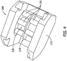
- the pump head 104 includes a casing 112, a rotor 114 with a keyed shaft 115, and a head clamp 116.
- the casing 112 defines an interior space 118 and at least partially encloses the rotor 114.
- the head clamp 116 compresses tubing 106 against the rotor 114.
- the rotor 114 rotates in relation to the casing 112 within the interior space 118.
- the servomotor 108 controls the rotation of the rotor 114 and transmits signals relating to the rotation of the rotor.
- a suitable pump head is a FLEXICON pump head available from WATSON-MARLOW, INC.
- the tubing 106 generally extends through the pump head 104 and transports fluid through the pump 102.
- the rotor 114 includes a plurality of rotor heads 120 that are spaced from the head clamp 116 a distance less than the outer diameter of the tubing 106.
- the tubing 106 is compressed between the rotor heads 120 and the head clamp 116.
- the rotor heads 120 move along the tubing 106 as the rotor 114 rotates.
- fluid in the tubing 106 is directed through the pump head 104 as the rotor 114 rotates.
- the pump 102 is a peristaltic pump.
- the pump 102 may dispense fluids at a speed of approximately 12 milliliters per second (mLs/sec) using 3.2 millimeter (mm) ID-tubing.
- the pump 102 of this embodiment dispenses liquids without the use of a nozzle.
- the volume of liquid dispensed may be in range of about 2.5 milliliters (mLs) to about 60 mLs.
- the accuracy limitations may depend on the size and type of the tubing 106. For example, a smaller ID tubing may allow greater accuracy for smaller dispense volumes.
- the tubing 106 is made of silicone. Accordingly, the tubing 106 may be removed and replaced to eliminate cross-contamination between batches, and to remove radioactively contaminated consumables from the area.
- the liquid handling systems may include any tubing that enables the liquid handling systems to operate as described.
- the liquid handling system 100 is able to withstand high levels of radiation.
- the pump head 104, shafts, couplings, motors, feedback mechanisms, and cabling are able to withstand high levels of radiation.
- Electrical cabling is insulated using materials, such as polyurethane, that are suitable to withstand high levels of radiation.
- a zero-backlash coupling 110 is positioned between the pump head 104 and the servomotor 108, keyed at the pump head shaft 115 and the motor shaft 122. Accordingly, the keyed coupling 110 eliminates backlash between the pump head 104 and rotor 114.
- the liquid handling system may include any coupling 110 that enables the liquid handling system to function as described.
- the servomotor 108 and pump head 104 are connected by the shafts 115, 122 and coupling 110.
- the shafts 115, 122, and the coupling 110 allow the servomotor 108 to be spaced from the pump head 104 and prevent backlash.
- the shaft 115 extends from the pump head 104 towards the servomotor.
- the shaft 122 extends from the servomotor 108 towards the pump head 104.
- the coupling 110 connects the shaft 115 and the shaft 122. At least one of the shafts 115, 122 is keyed to engage the keyed coupling 110 and prevent backlash during rotation of the rotor 114. In this embodiment, all of the shafts 115 and 122 are keyed to prevent the coupling moving relative axially, i.e., slipping, during operation of the pumps 102.
- the servomotor 108 rotates the shaft 122 which causes the coupling 110 and the shaft 115 to rotate.
- the shaft 115 is coupled to the rotor 114 (shown in FIG. 4 ) such that rotation of the shaft 115 causes the rotor 114 to rotate.
- the servomotor 108 and the pump head 104 may be connected in any manner that enables the pump 102 to operate as described.
- the pump head 104 and servomotor 108 are spaced apart and connected by the shafts 115, 122 and a plurality of couplings 110.
- the shafts 115, 122 and/or couplings 110 are angled to allow the pump head 104 and servomotor 108 to be spaced apart in more than one direction.
- the pump head 104 can be segregated and sealed in a clean environment for aseptic dispensing and sanitization, without exposing clean production areas to pump control hardware.
- the pump head 104 is a pharmaceutical-grade pump head.
- pharmaceutical-grade refers to equipment that is fabricated from non-oxidizing materials and withstands sanitization.
- pharmaceutical-grade equipment does not have recessed or pointed surfaces.
- pharmaceutical-grade equipment may be manufactured from 316 gauge stainless steel and include rounded corners and flush surfaces.
- the servomotor may be a servomotor 108 controlled by a programmable logic controller (PLC) to allow highly accurate and repeatable motion control.
- PLC programmable logic controller
- the servomotor 108 may be an AC servomotor with resolver feedback.
- the pump 102 may include any servomotors that enable the fluid application system to operate as described.
- the servomotor 108 can control pump head acceleration, deceleration, speed, and/or motion profile.
- the servomotor 108 can control acceleration of the rotor 114 (shown in FIG. 4 ) from a stopped position.
- the servomotor can maintain the rotor 114 at a steady state speed and can control deceleration of the rotor.
- the servomotor 108 can provide a desired motion profile including trapezoidal (linear ramp velocities) or S-curve (linear acceleration/deceleration).
- the relatively high torque capacity of the servomotor 108 and resolver-based feedback reduces stalling and slipping from commanded motion profiles.
- the servomotor 108 is suitably a high torque servomotor, such as a 480 volts of alternating current (3-phase) Servomotor with fine continuous resolver-based feedback.
- the coupling 110 between the servomotor 108 and the pump head 104 eliminates slippage and error due to the rotational inertia of the motor or pump head.
- High torque allows the servomotor 108 to overcome rotor resistance against liquid-filled tubing.
- the pump head 104 rotation and any other motion parameters may be controlled via one logic instruction.
- the servomotor 108 is equipped with a resolver-based feedback mechanism that is radiation-tolerant.
- a resolver 113 continuously tracks rotation of the rotor.
- the resolver is magnetic.
- the servomotor 108 withstands the radioactive environment better than other servomotors that may include optical encoders and may deteriorate and fail in radioactive environments.
- encoders include optics and electronics that do not withstand a high radiation environment without complete radiation shielding.
- the servomotor 108 does not include an encoder and/or electronic equipment that do not withstand radioactive environments.
- the servomotor 108 includes the resolver 113 that withstands the high radiation environment and does not require complete radiation shielding.
- the servomotor 108 may include any resolver that enables the servomotor to operate as described.
- the resolver 113 is omitted.
- the resolver 113 may provide feedback of at least about 200,000 steps per 360-degree revolution of the rotor 114 (shown in FIG. 3 ). Accordingly, the servomotor 108 may compare planned rotational movement to actual rotational movement for 1/200,000 th of a revolution while following a specific start-to-end motion profile. If rotation of the rotor 114 is interrupted for any reason (e.g. power loss, servo drive fault, etc.), the pump 102 is able to accurately recover and complete the original dispense because the resolver 113 automatically tracks exactly what portion of the original motion was completed, and what portion remains.
- any reason e.g. power loss, servo drive fault, etc.
- Embodiments of the servomotor 108 were tested by exposing the servomotors to 400 kilograys of ionizing radiation from a Cobalt-60 (Co-60) source.
- the Co-60 source provided an equivalent of 400000 Sv (40 Million REMs) gamma radiation exposure.
- the servomotor 108 was bench-tested before and after irradiation. Bench-testing results did not indicate a degradation of performance after irradiation.
- the tested exposure of 400 kilograys of radiation represents 20 years of expected Mo-99 radiation exposure at an unshielded worst-case proximity.
- the pumps 102 may be used to dispense non-radioactive fluid and/or radioactive fluid inside and outside of the hot cell.
- the pumps 102 may dispense acetic acid, purified water for injection, and/or any other liquids.
- the liquids may be used to activate a material in column assemblies, to wash column assemblies, and/or to test column assemblies.
- the pumps may be included in any cells of the system 10 such as an activation cell, a formulation cell, a fill cell, a wash cell, and an assay cell.
- the controller 200 includes at least one memory device 202 and a processor 204 that is coupled to the memory device 202 for executing instructions.
- executable instructions are stored in the memory device 202, and the controller 200 performs one or more operations described herein by programming the processor 204.
- the processor 204 may be programmed by encoding an operation as one or more executable instructions and by providing the executable instructions in the memory device 202.
- the processor 204 may include one or more processing units (e.g., in a multi-core configuration). Further, the processor 204 may be implemented using one or more heterogeneous processor systems in which a main processor is present with secondary processors on a single chip. As another illustrative example, the processor 204 may be a symmetric multi-processor system containing multiple processors of the same type. Further, the processor 204 may be implemented using any suitable programmable circuit including one or more systems and microcontrollers, microprocessors, programmable logic controllers (PLCs), reduced instruction set circuits (RISC), application specific integrated circuits (ASIC), programmable logic circuits, field programmable gate arrays (FPGA), and any other circuit capable of executing the functions described herein. In this embodiment, the processor 204 controls operation of the fluid handling systems by outputting control signals to components of the fluid handling system. Further, in this embodiment, the processor 204 determines a dispense volume based on program instructions and/or user inputs.
- PLCs programm
- the memory device 202 is one or more devices that enable information such as executable instructions and/or other data to be stored and retrieved.
- the memory device 202 may include one or more computer readable media, such as, without limitation, dynamic random access memory (DRAM), static random access memory (SRAM), a solid state disk, and/or a hard disk.
- DRAM dynamic random access memory
- SRAM static random access memory
- the memory device 202 may be configured to store, without limitation, application source code, application object code, source code portions of interest, object code portions of interest, configuration data, execution events and/or any other type of data.
- the controller 200 includes a presentation interface 206 that is connected to the processor 204.
- the presentation interface 206 presents information, such as application source code and/or execution events, to a user 212, such as a technician or operator.
- the presentation interface 206 may include a display adapter (not shown) that may be coupled to a display device, such as a cathode ray tube (CRT), a liquid crystal display (LCD), an organic LED (OLED) display, and/or an "electronic ink" display.
- the presentation interface 206 may include one or more display devices.
- the presentation interface 206 displays the dispense and/or transfer volumes of the fluid handling system.
- the controller 200 also includes a user input interface 208 in this embodiment.
- the user input interface 208 is connected to the processor 204 and receives input from the user 212.
- the user input interface 208 may include, for example, a keyboard, a pointing device, a mouse, a stylus, a touch sensitive panel (e.g., a touch pad or a touch screen), a gyroscope, an accelerometer, a position detector, and/or an audio user input interface.
- a single component, such as a touch screen may function as both a display device of the presentation interface 206 and the user input interface 208.
- the controller 200 further includes a communication interface 210 connected to the processor 204.
- the communication interface 210 communicates with one or more remote devices, such as the servomotor 108.
- the controller 200 is separated from the servomotor 108 and located outside of the radioactive environment.
- at least a portion of the controller 200 may be integrated with the servomotor 108.
- the controller 200 may include any component that enables the fluid handling system to operate as described.
- FIG. 5 is an isometric view of a fill station 18 of the system 10.
- FIG. 6 is a side view of the fill station 18.
- the fill station 18 includes two fill pumps 300 to dispense radioactive liquid inside the hot cells.
- the fill station may include any pump that enables the system 10 to operate as described.
- the fill station 18 includes arms 301 that rotate and support tubing 106. The arms 301 provide consistent support to the tubing 106 and prevent binding of the tubing.
- the fill station 18 includes two arms 301, one for each dispensing station.
- the fill station 18 may include any components that enable the fill station to operate as described.
- the fill pumps 300 may be used to dispense any nonradioactive and radioactive fluids.
- the fill pumps 300 dispense Mo-99 into the column assemblies.
- the fill pumps 300 dispense an accurate and precise amount of the radioactive liquid into the column assemblies within very strict tolerances.
- the fill pumps 300 may achieve dispense tolerances better than +/- 1.0% of a target volume, better than +/- 0.1% of a target volume, better than +/- 0.01 % of a target volume, better than +/- 0.001 % of a target volume, and even up to +/- 0.0001% of a target volume.
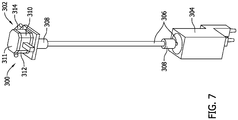
- FIG. 7 is an isometric view of one of the fill pumps 300.
- the fill pump 300 includes a pump head 302, a servomotor 304 with power and feedback cabling, keyed shafts 306, and keyed couplings 308.
- the shafts 306 and the couplings 308 extend between and connect the pump head 302 and the servomotor 304. Accordingly, the pump head 302 can be positioned in a clean processing area and the servomotor 304 can be positioned a distance from the pump head 302 to separate the servomotor from the clean processing area.
- the pump head 302 includes a head clamp 310, a casing 311, a rotor, a fluid inlet 314, and a fluid outlet 312.
- a head clamp 310 During operation of the pump 300, fluid enters the casing 311 through the fluid inlet 314, the fluid is directed through the pump head 302 by a rotor within the pump head 302, and the fluid exits the casing 311 through the fluid outlet 312.
- the keyed shafts 306 and couplings 308 allow the servomotor 304 to control rotational movement of the rotor within the pump head 302.
- the couplings 308 connect a middle shaft 306 to a pump head shaft 306 and a servomotor shaft 306.
- the couplings 308 are of zero-backlash type, and include keying features that prevent rotational slippage at the pump head shaft and at the servomotor shaft. Accordingly, the couplings 308 and the keyed shafts 306 eliminate backlash during motor and pump movement.
- the pump 300 may include any couplings and shafts that enable the pump 300 to operate as described.
- the servomotor 304 controls the pump head 302 and thus the dispensing of liquid.
- a programmable logic controller (PLC) controls an external servo drive, which controls servomotor 304, which precisely controls the pump head 302.
- Control is intrinsic to the PLC. Examples of control settings for the servomotor 304 are shown in the chart below.
- FIG. 8 is an isometric view of a formulation station 14 of the system 10.
- the formulation station 14 includes three pumps 400 to transfer bulk radioactive liquid inside hot cells.
- the bulk transfer pumps 400 may withdraw Mo-99 from shipping flasks and transfer the Mo-99 to a formulation vessel.
- the formulation station 14 may include any pump that enables the formulation station to operate as described.
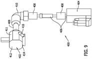
- FIG. 9 is an isometric view of one bulk transfer pump 400 of the formulation station 14.
- the bulk transfer pump 400 includes a pump head 402, a servomotor 404 with feedback and power cabling, keyed shafts 406, couplings 408, and an elbow 410.
- the shafts 406, couplings 408, and elbow 410 extend between and connect the pump head 402 and the servomotor 404.
- the pump 400 includes three couplings 408.
- One of the couplings 408 is disposed adjacent each of the pump head 402, the elbow 410, and the servomotor 404.
- the elbow 410 connects the servomotor 404 to the pump head 402 such that the servomotor 404 can be spaced from the pump head 402 in at least two directions.
- the couplings 408 and the elbow 410 allow the transfer pump 400 to be positioned to maximize space usage.
- the couplings 408 are of zero-backlash type, and include keying features that prevent rotational slippage at the pump head shaft 406 and at the motor shaft 406.
- the servomotor 404 is separated from the pump head 402 by a clean work table to prevent contamination of the fluid.
- the pump head 402 includes a head clamp 411, a casing 412, a rotor, a fluid inlet 414, and a fluid outlet 416.
- fluid enters the casing 412 through the fluid inlet 414, the fluid is directed through the pump head 402 by a rotor within the pump head 402, and the fluid exits the casing 412 through the fluid outlet 416.
- the shaft allows the servomotor 404 to control rotational movement of the rotor within the pump head 402.
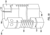
- FIG. 10 is a sectional view of a coupling 500 for use with the pumps 102, 300, and 400.
- the coupling 500 includes a first end portion 502, a second end portion 504, and a bellows 506 extending between the first end portion and the second end portion.
- the first end portion 502 and the second end portion 504 include openings 508 to receive shafts.
- the first end portion 502 and the second end portion include a keyway 510 to engage keyed shafts.
- the coupling 500 connects shafts together and prevents backlash between the shafts.
- a suitable coupling 500 is a Gerwah metal bellows coupling, series AKN, available from Ringfeeder Power Transmission, GMBH.
- a keyed shaft is inserted into the first end portion 502 and/or the second end portion 504 of the coupling such that a key of the shaft extends into and slides along the keyway 510.
- the keyed shaft and/or the coupling 500 is rotated to engage the key in the keyway 510.
- the coupling 500 and shaft may engage in any manner that enables the coupling 500 to function as described.
- the coupling 500 may be keyed and the shaft may include a keyway.
- the coupling 500 is cylindrical and extends linearly from the first end portion 502 to the second end portion 504. Accordingly, keyed shafts connected to the coupling 500 are aligned axially with each and with the coupling.
- the coupling 500 may have any shape and may extend in any direction.
- the coupling 500 may be angled to connect shafts extending in different directions.
- Embodiments of the systems and methods described provide several advantages over known systems. For example, embodiments of the systems and methods dispense accurate and precise volumes of nonradioactive and radioactive fluids.
- the fluid handling systems are not sensitive to radiation levels and can operate in radioactive environment without being shielded from the radiation.
- the fluid handling systems include a pump head connected to a servomotor via zero-backlash keyed couplings.
- the control components are segregated from the pump to allow the pump to be placed within the high radiation environment without control components deteriorating due to the radiation.
- the servomotor provides for continuous control of the pump head and includes an integrated resolver to provide feedback from the pump head.
- the fluid handling systems provide an increased pumping rate.
- Embodiments of the fluid handling systems reduce contamination during processing of radioactive materials.
- the fluid handling systems include disposable tubing that contains radiological contamination and may be replaced after use to eliminate chemical and biological contamination between batches.
- the fluid handling systems include pumps with servomotors that are separated from the clean processing area to reduce contamination.
- the pumps are not contaminated by the radioactive liquid and may be cleaned easily between batches.
- the pumps are quicker than systems such as stepper-driven syringe pumps, pneumatically-driven syringe pumps, and gravimetric dispensing pumps.
- the pumps do not require placing objects on a scale and are usable with a broader range of materials than at least some known pumps.
Landscapes
- Engineering & Computer Science (AREA)
- General Engineering & Computer Science (AREA)
- Mechanical Engineering (AREA)
- Physics & Mathematics (AREA)
- High Energy & Nuclear Physics (AREA)
- Infusion, Injection, And Reservoir Apparatuses (AREA)
- Health & Medical Sciences (AREA)
- Anesthesiology (AREA)
- Vascular Medicine (AREA)
- Biomedical Technology (AREA)
- Heart & Thoracic Surgery (AREA)
- Hematology (AREA)
- Life Sciences & Earth Sciences (AREA)
- Animal Behavior & Ethology (AREA)
- General Health & Medical Sciences (AREA)
- Public Health (AREA)
- Veterinary Medicine (AREA)
Description
- This application claims priority to
U.S. Provisional Patent Application Serial No. 62/331,651, filed May 4, 2016 U.S. Non-Provisional Patent Application Serial No. 15/394,272, filed December 29, 2016 - The field of the disclosure relates generally to liquid handling systems and, more particularly, to a pump for operation in a radioactive environment.
- Radioactive material is used in nuclear medicine for diagnostic and therapeutic purposes by injecting a patient with a small dose of the radioactive material, which concentrates in certain organs or regions of the patient. Radioactive materials typically used for nuclear medicine include Germanium-68 ("Ge-68"), Strontium-87m, Technetium-99m ("Tc-99m"), Indium-111m ("In-111"), lodine-131 ("I-131") and Thallium-201. Such radioactive materials may be produced using a radionuclide generator. Radionuclide generators generally include a column that has media for retaining a long-lived parent radionuclide that spontaneously decays into a daughter radionuclide that has a relatively short half-life. The column may be incorporated into a column assembly that has a needle-like outlet port that receives an evacuated vial to draw saline or other eluant liquid, provided to a needle-like inlet port, through a flow path of the column assembly, including the column itself. This liquid may elute and deliver daughter radionuclide from the column and to the evacuated vial for subsequent use in nuclear medical imaging applications, among other uses.
- During assembly of the radionuclide generators, radioactive materials may be formulated from a raw, concentrated form into a form having a desired concentration. For example, radioactive liquids may be homogeneously mixed, pH-adjusted, sampled, diluted, and dispensed. In addition, the radioactive liquids may be transferred between containers.
- A prior art system for assembling radionuclide generators is disclosed in patent document
JP 2006 -349649 A - Accordingly, a need exists for a liquid handling system that accurately and precisely dispenses liquids and is suitable for use with radioactive materials.
- This Background section is intended to introduce the reader to various aspects of art that may be related to various aspects of the present disclosure, which are described and/or claimed below. This discussion is believed to be helpful in providing the reader with background information to facilitate a better understanding of the various aspects of the present disclosure. Accordingly, it should be understood that these statements are to be read in this light, and not as admissions of prior art.
- In one aspect, a system for manufacturing radionuclide generators is provided. The system includes an enclosure defining a radioactive environment. The enclosure includes radiation shielding to prevent radiation within the radioactive environment from moving to an exterior of the enclosure. The system also includes a pump within the enclosure for transferring fluid through tubing. The pump includes a pump head including a casing, a rotor that rotates in relation to the casing, and a clamp. The tubing extends through the pump head. The clamp compresses the tubing against the rotor and directs radioactive fluid through the tubing as the rotor rotates. The pump also includes a servomotor that controls the rotation of the rotor and a coupling connecting the pump head to the servomotor. The coupling prevents backlash between the servomotor and the rotor during rotation.
- In another aspect, a pump for transferring fluid through tubing in a radioactive environment is provided. The pump includes a pump head including a casing, a rotor that rotates in relation to the casing, and a clamp. The tubing extends through the pump head. The clamp compresses the tubing against the rotor and directs radioactive fluid through the tubing as the rotor rotates. The rotor including a keyed shaft. The pump also includes a servomotor that controls the rotation of the rotor and includes a resolver to generate signals relating to the rotation of the rotor. The pump further includes a coupling connecting the pump head to the servomotor. The coupling is connected to the keyed shaft to prevent backlash between the servomotor and the rotor during rotation.
- In yet another aspect, a method of transferring fluid through tubing in a radioactive environment is provided. The tubing extends through a pump head of a pump. The pump includes a casing, a rotor that rotates in relation to the casing, and a clamp. The method includes compressing the tubing against the rotor and rotating the rotor to direct fluid through the tubing. The rotor includes a keyed shaft. The method also includes controlling rotation of the rotor using a servomotor connected to the rotor by the keyed shaft and a coupling. The method further includes engaging the coupling and the keyed shaft to prevent backlash between the servomotor and the rotor during rotation.
- Various refinements exist of the features noted in relation to the above-mentioned aspects. Further features may also be incorporated in the above-mentioned aspects as well. These refinements and additional features may exist individually or in any combination. For instance, various features discussed below in relation to any of the illustrated embodiments may be incorporated into any of the above-described aspects, alone or in any combination.
-
-
Figure 1 is a schematic view of a system for producing radionuclide generators. -
Figure 2 is a schematic view of a fluid handling system. -
Figure 3 is an isometric view of a pump head of the fluid handling system shown inFigure 2 . -
Figure 4 is an isometric view of the pump head with a head clamp removed to show a rotor of the pump head. -
Figure 5 is an isometric view of two dispense stations of the system shown inFigure 1 . -
Figure 6 is a side view of a fill station. -
Figure 7 is an isometric view of a dispensing pump of the fill station shown inFigure 6 . -
Figure 8 is an isometric view of a formulation station of the system shown inFigure 1 . -
Figure 9 is an isometric view of a pump of the formulation station shown inFigure 8 . -
Figure 10 is a sectional view of a coupling for use with the pumps shown inFigures 2 ,7 , and9 . - Corresponding reference characters indicate corresponding parts throughout the several views of the drawings.
-
FIG. 1 is a schematic view of asystem 10 for manufacturing radionuclide generators. Thesystem 10 shown inFIG. 1 may be used to produce various radionuclide generators, including, for example and without limitation, Technetium generators, Indium generators, and Strontium generators. Thesystem 10 ofFIG. 1 is particularly suited for producing Technetium generators. A Technetium generator is a pharmaceutical drug and device used to create sterile injectable solutions containing Tc-99m, an agent used in diagnostic imaging with a relatively short 6 hour radiological half-life, allowing the Tc-99m to be relatively quickly eliminated from human tissue. Tc-99m is "generated" via the natural decay of Molybdenum ("Mo-99"), which has a 66 hour half-life, which is desirable because it gives the generator a relatively long two week shelf life. During generator operation (i.e., elution with a saline solution), Mo-99 remains chemically bound to a core alumina bed (i.e., a retaining media) packed within the generator column, while Tc-99m washes free into an elution vial, ready for injection into a patient. While thesystem 10 is described herein with reference to Technetium generators, it is understood that thesystem 10 may be used to produce radionuclide generators other than Technetium generators. - As shown in
FIG. 1 , thesystem 10 generally includes a plurality of stations or cells. In the example embodiment, thesystem 10 includes acask loading station 12, aformulation station 14, anactivation station 16, a fill/wash station 18, an assay/autoclave loading station 20, an autoclave station ("Autoclaves") 22, anautoclave unloading station 24, a quality control testing station 26, a shieldingstation 28, and apackaging station 30. - The
cask loading station 12 is configured to receive and handle casks or containers of radioactive material, such as a parent radionuclide, and transfer the radioactive material to theformulation station 14. Radioactive material may be transported in secondary containment vessels and flasks that need to be removed from an outer cask prior to formulation. Thecask loading station 12 includes suitable tooling and mechanisms to extract secondary containment vessels and flasks from outer casks, as well as to transfer flasks to the formulation cell. Suitable devices that may be used in the cask loading station include, for example and without limitation, telemanipulators. - At the
formulation station 14, the raw radioactive material (i.e., Mo-99) is quality control tested, chemically treated if necessary, and then pH adjusted while diluting the raw radioactive material to a desired final target concentration. The formulated radioactive material is stored in a suitable containment vessel (e.g., within the formulation station 14). - Column assemblies containing a column of retaining media (e.g., alumina) are activated at the
activation station 16 to facilitate binding of the formulated radioactive material with the retaining media. In some embodiments, column assemblies are activated by eluting the column assemblies with a suitable volume of hydrogen chloride (HCI) at a suitable pH level. Column assemblies are held for a minimum wait time prior to charging the column assemblies with the parent radionuclide. - Following activation, column assemblies are loaded into the fill/
wash station 18 using a suitable transfer mechanism (e.g., transfer drawer). Each column assembly is then charged with parent radionuclide by eluting formulated radioactive solution (e.g., Mo-99) from theformulation station 14 through individual column assemblies using suitable liquid handling systems (e.g., pumps, valves, etc.). The volume of formulated radioactive solution eluted through each column assembly is based on the desired curie (Ci) activity for the corresponding column assembly. The volume eluted through each column assembly is equivalent to the total Ci activity identified at the time of calibration for the column assembly. For example, if a volume of formulated Mo-99 required to make a 1.0 Ci Generator (at time of calibration) is 'X', the volume required to make a 19.0Ci Generator is simply 19 times X. After a minimum wait time, the charged column assemblies are eluted with a suitable volume and concentration of acetic acid, followed by an elution with a suitable volume and concentration of saline to "wash" the column assemblies. Column assemblies are held for a minimum wait time before performing assays on the column assemblies. - The charged and washed column assemblies are then transferred to the assay/
autoclave load station 20, in which assays are taken from each column assembly to check the amount of parent and daughter radionuclide produced during elution. Each column assembly is eluted with a suitable volume of saline, and the resulting solution is assayed to check the parent and daughter radionuclide levels in the assay. Where the radioactive material is Mo-99, the elutions are assayed for both Tc-99m and Mo-99. Column assemblies having a daughter radionuclide (e.g., Tc-99m) assay falling outside an acceptable range calculation are rejected. Column assemblies having a parent radionuclide (e.g., Mo-99) breakthrough exceeding a maximum acceptable limit are also rejected. - Following the assay process, tip caps are applied to the outlet port and the fill port of the column assembly. Column assemblies may be provided with tip caps already applied to the inlet port. If the column assembly is not provided with a tip cap pre-applied to the inlet port, a tip cap may be applied prior to, subsequent to, or concurrently with tip caps being applied to the outlet port and the fill port. Assayed, tip-capped column assemblies are then loaded into an autoclave sterilizer located in the autoclave station for terminal sterilization. The sealed column assemblies are subjected to an autoclave sterilization process within the autoclave station to produce terminally-sterilized column assemblies.
- Following the autoclave sterilization cycle, column assemblies are unloaded from the autoclave station into the
autoclave unloading station 24. Column assemblies are then transferred to the shieldingstation 28 for shielding. - Some of the column assemblies are transferred to the quality control testing station 26 for quality control. In the example embodiment, the quality control testing station 26 includes a QC testing isolator that is sanitized prior to QC testing, and maintained at a positive pressure and a Grade A clean room environment to minimize possible sources of contamination. Column assemblies are aseptically eluted for in-process QC sampling, and subjected to sterility testing within the isolator of the quality control testing station 26. New tip caps are applied to the inlet and outlet needles of the column assemblies before the column assemblies are transferred back to the
autoclave unloading station 24. - The
system 10 includes a suitable transfer mechanism for transferring column assemblies from the autoclave unloading station 24 (which is maintained at a negative pressure differential, Grade B clean room environment) to the isolator of the quality control testing station 26. In some embodiments, column assemblies subjected to quality control testing may be transferred from the quality control testing station 26 back to theautoclave unloading station 24, and can be re-sterilized and re-tested, or re-sterilized and packaged for shipment. In other embodiments, column assemblies are discarded after being subjected to QC testing. - In the shielding
station 28, column assemblies from theautoclave unloading station 24 are visually inspected for container closure part presence, and then placed within a radiation-shielding container (e.g., a lead plug). The radiation shielding container is inserted into an appropriate safe constructed of suitable radiation shielding material (e.g., lead, tungsten or depleted uranium). Shielded column assemblies are then released from the shieldingstation 28. - In the
packaging station 30, shielded column assemblies from the shieldingstation 28 are placed in buckets pre-labeled with appropriate regulatory (e.g., FDA) labels. A label uniquely identifying each generator is also printed and applied to each bucket. A hood is then applied to each bucket. A handle is then applied to each hood. - The
system 10 may generally include any suitable transport systems and devices to facilitate transferring column assemblies between stations. In some embodiments, for example, each of the stations includes at least one telemanipulator to allow an operator outside the hot cell environment (i.e., within the surrounding room or lab) to manipulate and transfer column assemblies within the hot cell environment. Moreover, in some embodiments, thesystem 10 includes a conveyance system to automatically transport column assemblies between the stations and/or between substations within one or more of the stations (e.g., between a fill substation and a wash substation within the fill/wash station 18). - In the example embodiment, some stations of the
system 10 include and/or are enclosed within a shielded nuclear radiation containment chamber, also referred to herein as a "hot cell". Hot cells generally include an enclosure constructed of nuclear radiation shielding material designed to shield the surrounding environment from nuclear radiation. Suitable shielding materials from which hot cells may be constructed include, for example and without limitation, lead, depleted uranium, and tungsten. In some embodiments, hot cells are constructed of steel-clad lead walls forming a cuboid or rectangular prism. In some embodiments, a hot cell may include a viewing window constructed of a transparent shielding material. Suitable materials from which viewing windows may be constructed include, for example and without limitation, lead glass. In the example embodiment, each of thecask loading station 12, theformulation station 14, the fill/wash station 18, the assay/autoclave loading station 20, the autoclave station, theautoclave unloading station 24, and the shieldingstation 28 include and/or are enclosed within a hot cell. - In some embodiments, one or more of the stations are maintained at a certain clean room grade (e.g., Grade B or Grade C). In the example embodiment, pre-autoclave hot cells (i.e., the
cask loading station 12, theformulation station 14, the fill/wash station 18, the assay/autoclave loading station 20) are maintained at a Grade C clean room environment, and the autoclave unloading cell orstation 24 is maintained at a Grade B clean room environment. The shieldingstation 28 is maintained at a Grade C clean room environment. Thepackaging station 30 is maintained at a Grade D clean room environment. - Additionally, the pressure within one or more stations of the
system 10 may be controlled at a negative or positive pressure differential relative to the surrounding environment and/or relative to adjacent cells or stations. In some embodiments, for example, all hot cells are maintained at a negative pressure relative to the surrounding environment. Moreover, in some embodiments, the isolator of the quality control testing station 26 is maintained at a positive pressure relative to the surrounding environment and/or relative to adjacent stations of the system 10 (e.g., relative to the autoclave unloading station 24). - In this embodiment, the
system 10 includes liquid handling systems for handling liquids quickly, accurately, and precisely. At least some of the liquid handling systems are disposed in the hot cells and/or handle radioactive liquids. Accordingly, the liquid handling systems may withstand radiation that would harm people and most electronic equipment. For example, the liquid handling systems may handle a Molybdenum-99 (Mo-99) solution which may deliver a lethal radiation dose in less than 5 minutes to an unprotected observer standing approximately 30 cm (12 inches) away. In other words, operators in the area of the Mo-99 solution would be exposed to a field equal to 54 Sv (5.4 Million millirem) per hour (mREM/hr), or 54,000 times greater than the Nuclear Regulatory Commission standard for a high radiation area. As used throughout this disclosure, the term "high radiation area" refers to an area in which radiation levels exceed 1 mSv/h (100 mREM/hr) at 30 centimeters from the radiation source. - The described liquid handling systems withstand the relatively high radiation doses in the high radiation area with minimal deterioration. Moreover, the liquid handling systems are unshielded to reduce the amount of space occupied by the liquid handling systems. The liquid handling systems may be used to transport any liquids, including radioactive and nonradioactive materials. For example, the liquid handling systems may dispense high radioactive pharmaceutical liquids such as clean injectable solutions. At least some of the liquid handling systems automatically dispense the liquids. In alternative embodiments, the
system 10 may include any liquid handling systems that enable thesystem 10 to operate as described. -
FIG. 2 is a schematic view of aliquid handling system 100 for use with thesystem 10. In this embodiment, theliquid handling system 100 includes at least onepositive displacement pump 102, or more specifically, a peristaltic pump, and acontroller 200. Eachpump 102 includes apump head 104,tubing 106, aservomotor 108 with power and feedback cabling, and acoupling 110 connecting the pump head to the servomotor. - In reference to
FIGS. 2 ,3 and4 , thepump head 104 includes acasing 112, arotor 114 with akeyed shaft 115, and ahead clamp 116. Thecasing 112 defines aninterior space 118 and at least partially encloses therotor 114. Thehead clamp 116 compressestubing 106 against therotor 114. Therotor 114 rotates in relation to thecasing 112 within theinterior space 118. Theservomotor 108 controls the rotation of therotor 114 and transmits signals relating to the rotation of the rotor. One example of a suitable pump head is a FLEXICON pump head available from WATSON-MARLOW, INC. - The
tubing 106 generally extends through thepump head 104 and transports fluid through thepump 102. Therotor 114 includes a plurality of rotor heads 120 that are spaced from the head clamp 116 a distance less than the outer diameter of thetubing 106. Thetubing 106 is compressed between the rotor heads 120 and thehead clamp 116. The rotor heads 120 move along thetubing 106 as therotor 114 rotates. As a result, fluid in thetubing 106 is directed through thepump head 104 as therotor 114 rotates. Accordingly, in this embodiment thepump 102 is a peristaltic pump. - For example, the
pump 102 may dispense fluids at a speed of approximately 12 milliliters per second (mLs/sec) using 3.2 millimeter (mm) ID-tubing. Thepump 102 of this embodiment dispenses liquids without the use of a nozzle. The volume of liquid dispensed may be in range of about 2.5 milliliters (mLs) to about 60 mLs. The accuracy limitations may depend on the size and type of thetubing 106. For example, a smaller ID tubing may allow greater accuracy for smaller dispense volumes. In this embodiment, thetubing 106 is made of silicone. Accordingly, thetubing 106 may be removed and replaced to eliminate cross-contamination between batches, and to remove radioactively contaminated consumables from the area. In alternative embodiments, the liquid handling systems may include any tubing that enables the liquid handling systems to operate as described. - The
liquid handling system 100 is able to withstand high levels of radiation. For example, thepump head 104, shafts, couplings, motors, feedback mechanisms, and cabling are able to withstand high levels of radiation. Electrical cabling is insulated using materials, such as polyurethane, that are suitable to withstand high levels of radiation. - In reference to
FIG. 2 , in this embodiment, a zero-backlash coupling 110 is positioned between thepump head 104 and theservomotor 108, keyed at thepump head shaft 115 and themotor shaft 122. Accordingly, thekeyed coupling 110 eliminates backlash between thepump head 104 androtor 114. In alternative embodiments, the liquid handling system may include anycoupling 110 that enables the liquid handling system to function as described. - The
servomotor 108 and pumphead 104 are connected by theshafts coupling 110. Theshafts coupling 110 allow theservomotor 108 to be spaced from thepump head 104 and prevent backlash. In particular, theshaft 115 extends from thepump head 104 towards the servomotor. Theshaft 122 extends from theservomotor 108 towards thepump head 104. Thecoupling 110 connects theshaft 115 and theshaft 122. At least one of theshafts keyed coupling 110 and prevent backlash during rotation of therotor 114. In this embodiment, all of theshafts pumps 102. - During operation, the
servomotor 108 rotates theshaft 122 which causes thecoupling 110 and theshaft 115 to rotate. Theshaft 115 is coupled to the rotor 114 (shown inFIG. 4 ) such that rotation of theshaft 115 causes therotor 114 to rotate. In alternative embodiments, theservomotor 108 and thepump head 104 may be connected in any manner that enables thepump 102 to operate as described. - In some embodiments, the
pump head 104 andservomotor 108 are spaced apart and connected by theshafts couplings 110. In further embodiments, theshafts couplings 110 are angled to allow thepump head 104 andservomotor 108 to be spaced apart in more than one direction. In addition, thepump head 104 can be segregated and sealed in a clean environment for aseptic dispensing and sanitization, without exposing clean production areas to pump control hardware. In some embodiments, thepump head 104 is a pharmaceutical-grade pump head. As used herein, the term "pharmaceutical-grade" refers to equipment that is fabricated from non-oxidizing materials and withstands sanitization. In addition, pharmaceutical-grade equipment does not have recessed or pointed surfaces. For example, pharmaceutical-grade equipment may be manufactured from 316 gauge stainless steel and include rounded corners and flush surfaces. - The servomotor may be a
servomotor 108 controlled by a programmable logic controller (PLC) to allow highly accurate and repeatable motion control. In addition, theservomotor 108 may be an AC servomotor with resolver feedback. In alternative embodiments, thepump 102 may include any servomotors that enable the fluid application system to operate as described. - The
servomotor 108 can control pump head acceleration, deceleration, speed, and/or motion profile. For example, theservomotor 108 can control acceleration of the rotor 114 (shown inFIG. 4 ) from a stopped position. In addition, the servomotor can maintain therotor 114 at a steady state speed and can control deceleration of the rotor. Moreover, theservomotor 108 can provide a desired motion profile including trapezoidal (linear ramp velocities) or S-curve (linear acceleration/deceleration). The relatively high torque capacity of theservomotor 108 and resolver-based feedback reduces stalling and slipping from commanded motion profiles. For example, theservomotor 108 is suitably a high torque servomotor, such as a 480 volts of alternating current (3-phase) Servomotor with fine continuous resolver-based feedback. Thecoupling 110 between theservomotor 108 and thepump head 104 eliminates slippage and error due to the rotational inertia of the motor or pump head. High torque allows theservomotor 108 to overcome rotor resistance against liquid-filled tubing. Thepump head 104 rotation and any other motion parameters may be controlled via one logic instruction. - The
servomotor 108 is equipped with a resolver-based feedback mechanism that is radiation-tolerant. Aresolver 113 continuously tracks rotation of the rotor. In this embodiment, the resolver is magnetic. Accordingly, theservomotor 108 withstands the radioactive environment better than other servomotors that may include optical encoders and may deteriorate and fail in radioactive environments. For example, encoders include optics and electronics that do not withstand a high radiation environment without complete radiation shielding. In contrast to such systems, in this embodiment, theservomotor 108 does not include an encoder and/or electronic equipment that do not withstand radioactive environments. Theservomotor 108 includes theresolver 113 that withstands the high radiation environment and does not require complete radiation shielding. In alternative embodiments, theservomotor 108 may include any resolver that enables the servomotor to operate as described. In further embodiments, theresolver 113 is omitted. - The
resolver 113 may provide feedback of at least about 200,000 steps per 360-degree revolution of the rotor 114 (shown inFIG. 3 ). Accordingly, theservomotor 108 may compare planned rotational movement to actual rotational movement for 1/200,000th of a revolution while following a specific start-to-end motion profile. If rotation of therotor 114 is interrupted for any reason (e.g. power loss, servo drive fault, etc.), thepump 102 is able to accurately recover and complete the original dispense because theresolver 113 automatically tracks exactly what portion of the original motion was completed, and what portion remains. - Embodiments of the servomotor 108 (including the integrated resolver 113) were tested by exposing the servomotors to 400 kilograys of ionizing radiation from a Cobalt-60 (Co-60) source. The Co-60 source provided an equivalent of 400000 Sv (40 Million REMs) gamma radiation exposure. The
servomotor 108 was bench-tested before and after irradiation. Bench-testing results did not indicate a degradation of performance after irradiation. The tested exposure of 400 kilograys of radiation represents 20 years of expected Mo-99 radiation exposure at an unshielded worst-case proximity. - The
pumps 102 may be used to dispense non-radioactive fluid and/or radioactive fluid inside and outside of the hot cell. For example, thepumps 102 may dispense acetic acid, purified water for injection, and/or any other liquids. The liquids may be used to activate a material in column assemblies, to wash column assemblies, and/or to test column assemblies. Accordingly, the pumps may be included in any cells of thesystem 10 such as an activation cell, a formulation cell, a fill cell, a wash cell, and an assay cell. - In reference to
FIG. 2 , thecontroller 200 includes at least onememory device 202 and aprocessor 204 that is coupled to thememory device 202 for executing instructions. In this embodiment, executable instructions are stored in thememory device 202, and thecontroller 200 performs one or more operations described herein by programming theprocessor 204. For example, theprocessor 204 may be programmed by encoding an operation as one or more executable instructions and by providing the executable instructions in thememory device 202. - The
processor 204 may include one or more processing units (e.g., in a multi-core configuration). Further, theprocessor 204 may be implemented using one or more heterogeneous processor systems in which a main processor is present with secondary processors on a single chip. As another illustrative example, theprocessor 204 may be a symmetric multi-processor system containing multiple processors of the same type. Further, theprocessor 204 may be implemented using any suitable programmable circuit including one or more systems and microcontrollers, microprocessors, programmable logic controllers (PLCs), reduced instruction set circuits (RISC), application specific integrated circuits (ASIC), programmable logic circuits, field programmable gate arrays (FPGA), and any other circuit capable of executing the functions described herein. In this embodiment, theprocessor 204 controls operation of the fluid handling systems by outputting control signals to components of the fluid handling system. Further, in this embodiment, theprocessor 204 determines a dispense volume based on program instructions and/or user inputs. - The
memory device 202 is one or more devices that enable information such as executable instructions and/or other data to be stored and retrieved. Thememory device 202 may include one or more computer readable media, such as, without limitation, dynamic random access memory (DRAM), static random access memory (SRAM), a solid state disk, and/or a hard disk. Thememory device 202 may be configured to store, without limitation, application source code, application object code, source code portions of interest, object code portions of interest, configuration data, execution events and/or any other type of data. - In this embodiment, the
controller 200 includes apresentation interface 206 that is connected to theprocessor 204. Thepresentation interface 206 presents information, such as application source code and/or execution events, to auser 212, such as a technician or operator. For example, thepresentation interface 206 may include a display adapter (not shown) that may be coupled to a display device, such as a cathode ray tube (CRT), a liquid crystal display (LCD), an organic LED (OLED) display, and/or an "electronic ink" display. Thepresentation interface 206 may include one or more display devices. In this embodiment, thepresentation interface 206 displays the dispense and/or transfer volumes of the fluid handling system. - The
controller 200 also includes auser input interface 208 in this embodiment. Theuser input interface 208 is connected to theprocessor 204 and receives input from theuser 212. Theuser input interface 208 may include, for example, a keyboard, a pointing device, a mouse, a stylus, a touch sensitive panel (e.g., a touch pad or a touch screen), a gyroscope, an accelerometer, a position detector, and/or an audio user input interface. A single component, such as a touch screen, may function as both a display device of thepresentation interface 206 and theuser input interface 208. - In this embodiment, the
controller 200 further includes a communication interface 210 connected to theprocessor 204. The communication interface 210 communicates with one or more remote devices, such as theservomotor 108. In this embodiment, thecontroller 200 is separated from theservomotor 108 and located outside of the radioactive environment. In some embodiments, at least a portion of thecontroller 200 may be integrated with theservomotor 108. In alternative embodiments, thecontroller 200 may include any component that enables the fluid handling system to operate as described. -
FIG. 5 is an isometric view of afill station 18 of thesystem 10.FIG. 6 is a side view of thefill station 18. Thefill station 18 includes twofill pumps 300 to dispense radioactive liquid inside the hot cells. In alternative embodiments, the fill station may include any pump that enables thesystem 10 to operate as described. In addition, thefill station 18 includesarms 301 that rotate andsupport tubing 106. Thearms 301 provide consistent support to thetubing 106 and prevent binding of the tubing. In this embodiment, thefill station 18 includes twoarms 301, one for each dispensing station. In alternative embodiments, thefill station 18 may include any components that enable the fill station to operate as described. - The fill pumps 300 may be used to dispense any nonradioactive and radioactive fluids. In this embodiment, the fill pumps 300 dispense Mo-99 into the column assemblies. The fill pumps 300 dispense an accurate and precise amount of the radioactive liquid into the column assemblies within very strict tolerances. For example, the fill pumps 300 may achieve dispense tolerances better than +/- 1.0% of a target volume, better than +/- 0.1% of a target volume, better than +/- 0.01 % of a target volume, better than +/- 0.001 % of a target volume, and even up to +/- 0.0001% of a target volume.
-
FIG. 7 is an isometric view of one of the fill pumps 300. Thefill pump 300 includes apump head 302, aservomotor 304 with power and feedback cabling, keyedshafts 306, and keyedcouplings 308. Theshafts 306 and thecouplings 308 extend between and connect thepump head 302 and theservomotor 304. Accordingly, thepump head 302 can be positioned in a clean processing area and theservomotor 304 can be positioned a distance from thepump head 302 to separate the servomotor from the clean processing area. - The
pump head 302 includes ahead clamp 310, acasing 311, a rotor, afluid inlet 314, and afluid outlet 312. During operation of thepump 300, fluid enters thecasing 311 through thefluid inlet 314, the fluid is directed through thepump head 302 by a rotor within thepump head 302, and the fluid exits thecasing 311 through thefluid outlet 312. - The
keyed shafts 306 andcouplings 308 allow theservomotor 304 to control rotational movement of the rotor within thepump head 302. In particular, thecouplings 308 connect amiddle shaft 306 to apump head shaft 306 and aservomotor shaft 306. Thecouplings 308 are of zero-backlash type, and include keying features that prevent rotational slippage at the pump head shaft and at the servomotor shaft. Accordingly, thecouplings 308 and thekeyed shafts 306 eliminate backlash during motor and pump movement. In alternative embodiments, thepump 300 may include any couplings and shafts that enable thepump 300 to operate as described. - The
servomotor 304 controls thepump head 302 and thus the dispensing of liquid. A programmable logic controller (PLC) controls an external servo drive, which controlsservomotor 304, which precisely controls thepump head 302. Control is intrinsic to the PLC. Examples of control settings for theservomotor 304 are shown in the chart below. -
Setting Fill Low Volume Fill High Volume Dispense Volume (mL) < 12.0 >= 12.0 Velocity (mL/s) 13.0 13.0 Acceleration (mL/s2) 20.0 40.0 Deceleration (mL/s2) 40.0 20.0 Motion Profile S-Curve S-Curve -
FIG. 8 is an isometric view of aformulation station 14 of thesystem 10. Theformulation station 14 includes threepumps 400 to transfer bulk radioactive liquid inside hot cells. For example, the bulk transfer pumps 400 may withdraw Mo-99 from shipping flasks and transfer the Mo-99 to a formulation vessel. In alternative embodiments, theformulation station 14 may include any pump that enables the formulation station to operate as described. -
FIG. 9 is an isometric view of onebulk transfer pump 400 of theformulation station 14. Thebulk transfer pump 400 includes apump head 402, aservomotor 404 with feedback and power cabling, keyedshafts 406,couplings 408, and anelbow 410. Theshafts 406,couplings 408, andelbow 410 extend between and connect thepump head 402 and theservomotor 404. Thepump 400 includes threecouplings 408. One of thecouplings 408 is disposed adjacent each of thepump head 402, theelbow 410, and theservomotor 404. Theelbow 410 connects theservomotor 404 to thepump head 402 such that theservomotor 404 can be spaced from thepump head 402 in at least two directions. Moreover, thecouplings 408 and theelbow 410 allow thetransfer pump 400 to be positioned to maximize space usage. Thecouplings 408 are of zero-backlash type, and include keying features that prevent rotational slippage at thepump head shaft 406 and at themotor shaft 406. Theservomotor 404 is separated from thepump head 402 by a clean work table to prevent contamination of the fluid. - The
pump head 402 includes ahead clamp 411, acasing 412, a rotor, afluid inlet 414, and afluid outlet 416. During operation of thepump 400, fluid enters thecasing 412 through thefluid inlet 414, the fluid is directed through thepump head 402 by a rotor within thepump head 402, and the fluid exits thecasing 412 through thefluid outlet 416. The shaft allows theservomotor 404 to control rotational movement of the rotor within thepump head 402. -
FIG. 10 is a sectional view of acoupling 500 for use with thepumps coupling 500 includes afirst end portion 502, asecond end portion 504, and abellows 506 extending between the first end portion and the second end portion. Thefirst end portion 502 and thesecond end portion 504 includeopenings 508 to receive shafts. In addition, thefirst end portion 502 and the second end portion include akeyway 510 to engage keyed shafts. Accordingly, thecoupling 500 connects shafts together and prevents backlash between the shafts. One example of asuitable coupling 500 is a Gerwah metal bellows coupling, series AKN, available from Ringfeeder Power Transmission, GMBH. - During operation, a keyed shaft is inserted into the
first end portion 502 and/or thesecond end portion 504 of the coupling such that a key of the shaft extends into and slides along thekeyway 510. The keyed shaft and/or thecoupling 500 is rotated to engage the key in thekeyway 510. In alternative embodiments, thecoupling 500 and shaft may engage in any manner that enables thecoupling 500 to function as described. For example, in some embodiments, thecoupling 500 may be keyed and the shaft may include a keyway. - In this embodiment, the
coupling 500 is cylindrical and extends linearly from thefirst end portion 502 to thesecond end portion 504. Accordingly, keyed shafts connected to thecoupling 500 are aligned axially with each and with the coupling. In alternative embodiments, thecoupling 500 may have any shape and may extend in any direction. For example, in some embodiments, thecoupling 500 may be angled to connect shafts extending in different directions. - Embodiments of the systems and methods described provide several advantages over known systems. For example, embodiments of the systems and methods dispense accurate and precise volumes of nonradioactive and radioactive fluids. In addition, the fluid handling systems are not sensitive to radiation levels and can operate in radioactive environment without being shielded from the radiation. For example, the fluid handling systems include a pump head connected to a servomotor via zero-backlash keyed couplings. The control components are segregated from the pump to allow the pump to be placed within the high radiation environment without control components deteriorating due to the radiation. The servomotor provides for continuous control of the pump head and includes an integrated resolver to provide feedback from the pump head. Moreover, the fluid handling systems provide an increased pumping rate.
- Embodiments of the fluid handling systems reduce contamination during processing of radioactive materials. The fluid handling systems include disposable tubing that contains radiological contamination and may be replaced after use to eliminate chemical and biological contamination between batches. Moreover, the fluid handling systems include pumps with servomotors that are separated from the clean processing area to reduce contamination. The pumps are not contaminated by the radioactive liquid and may be cleaned easily between batches. Also, the pumps are quicker than systems such as stepper-driven syringe pumps, pneumatically-driven syringe pumps, and gravimetric dispensing pumps. In addition, the pumps do not require placing objects on a scale and are usable with a broader range of materials than at least some known pumps.
- When introducing elements of the present invention or the embodiment(s) thereof, the articles "a", "an", "the" and "said" are intended to mean that there are one or more of the elements. The terms "comprising", "including" and "having" are intended to be inclusive and mean that there may be additional elements other than the listed elements.
- As various changes could be made in the above constructions and methods without departing from the scope of the invention, it is intended that all matter contained in the above description and shown in the accompanying drawings shall be interpreted as illustrative and not in a limiting sense.
Claims (15)
- A system (10) for manufacturing radionuclide generators, the system comprising:an enclosure defining a radioactive environment, the enclosure including radiation shielding to prevent radiation within the radioactive environment from moving to an exterior of the enclosure; anda pump (102) within the enclosure for transferring fluid through tubing, characterised by the pump comprising:a pump (104) head including a casing (112), a rotor (114) that rotates in relation to the casing, and a clamp (116), the tubing extending through the pump head, the clamp compressing the tubing against the rotor and directing radioactive fluid through the tubing as the rotor rotates;a servomotor (108) that controls the rotation of the rotor; anda coupling (110) connecting the pump head to the servomotor, wherein the coupling prevents backlash between the servomotor and the rotor during rotation.
- The system of claim 1, wherein the servomotor includes a resolver (113) to generate signals relating to the rotation of the rotor.
- The system of claim 1, wherein the pump further comprises cables connected to the servomotor, the cables including polyurethane insulation to resist the effects of radiation.
- The system of claim 1, wherein the pump further comprises:a first keyed shaft (115) extending between the coupling and the rotor, wherein the first keyed shaft is engaged with the coupling; anda second keyed shaft (122) extending between the coupling and the servomotor, wherein the second keyed shaft is engaged with the coupling.
- The system of claim 1, wherein the coupling is a first coupling, the pump further comprising a second coupling and a shaft extending between the first coupling and the second coupling.
- The system of claim 1, wherein the pump head is a peristaltic pump head and is positioned within a clean environment, and wherein the pump head is separated from the servomotor to prevent contamination of the fluid.
- A pump (102) for transferring fluid through tubing in a radioactive environment, said pump comprising:a pump head (104) including a casing (112), a rotor (114) that rotates in relation to the casing, and a clamp, the tubing extending through the pump head, the clamp compressing the tubing against the rotor and directing radioactive fluid through the tubing as the rotor rotates, the rotor including a keyed shaft;a servomotor (108) that controls the rotation of the rotor and includes a resolver to generate signals relating to the rotation of the rotor; anda coupling (110) connecting the pump head to the servomotor, wherein the coupling is connected to the keyed shaft to prevent backlash between the servomotor and the rotor during rotation.
- The pump of claim 7 wherein the pump head and servomotor are positioned in a high radiation enclosure, the pump further comprising cables connected to the servomotor, the cables including polyurethane insulation to resist the effects of radiation.
- The pump of claim 7, wherein the coupling defines a keyway to engage the keyed shaft, the pump further comprising a second keyed shaft extending between the coupling and the servomotor, wherein the second keyed shaft is connected to the coupling.
- The pump of claim 7, wherein the coupling is a first coupling, the pump further comprising a second coupling and a shaft extending between the first coupling and the second coupling.
- The pump of claim 7, wherein the pump head is a pharmaceutical-grade peristaltic pump head, and wherein the pump head is positioned within a clean environment and is separated from the servomotor to prevent contamination of the fluid.
- A method of transferring fluid through tubing in a radioactive environment, the tubing extending through a pump head of a pump, the pump including a casing, a rotor that rotates in relation to the casing, and a clamp, the method comprising:compressing the tubing against the rotor;rotating the rotor to direct fluid through the tubing, the rotor including a keyed shaft;controlling rotation of the rotor using a servomotor connected to the rotor by the keyed shaft and a coupling; andengaging the coupling and the keyed shaft to prevent backlash between the servomotor and the rotor during rotation.
- The method of claim 12 further comprising generating signals relating to the rotation of the rotor using a resolver of the servomotor; and
dispensing the fluid into a container, wherein the servomotor is configured to control a dispense volume of the fluid. - The method of claim 12 wherein the pump head and servomotor are positioned in a high radiation enclosure, the method further comprising supplying power to the servomotor through cables connected to the servomotor, the cables including polyurethane insulation to resist the effects of radiation.
- The method of claim 12 further comprising:engaging the coupling and a second keyed shaft extending between the coupling and the servomotor; androtating the keyed shaft and the coupling to cause rotation of the rotor.
Priority Applications (1)
| Application Number | Priority Date | Filing Date | Title |
|---|---|---|---|
| PL16829215T PL3452722T3 (en) | 2016-05-04 | 2016-12-30 | Pump for operation in radioactive environment |
Applications Claiming Priority (3)
| Application Number | Priority Date | Filing Date | Title |
|---|---|---|---|
| US201662331651P | 2016-05-04 | 2016-05-04 | |
| US15/394,272 US10578094B2 (en) | 2016-05-04 | 2016-12-29 | Pump for operation in radioactive environment |
| PCT/US2016/069409 WO2017192182A1 (en) | 2016-05-04 | 2016-12-30 | Pump for operation in radioactive environment |
Publications (2)
| Publication Number | Publication Date |
|---|---|
| EP3452722A1 EP3452722A1 (en) | 2019-03-13 |
| EP3452722B1 true EP3452722B1 (en) | 2020-05-27 |
Family
ID=57861277
Family Applications (1)
| Application Number | Title | Priority Date | Filing Date |
|---|---|---|---|
| EP16829215.9A Active EP3452722B1 (en) | 2016-05-04 | 2016-12-30 | Pump for operation in radioactive environment |
Country Status (6)
| Country | Link |
|---|---|
| US (1) | US10578094B2 (en) |
| EP (1) | EP3452722B1 (en) |
| CA (1) | CA3021706C (en) |
| ES (1) | ES2803274T3 (en) |
| PL (1) | PL3452722T3 (en) |
| WO (1) | WO2017192182A1 (en) |
Family Cites Families (56)
| Publication number | Priority date | Publication date | Assignee | Title |
|---|---|---|---|---|
| US3574485A (en) | 1958-11-28 | 1971-04-13 | Broido Louis | Method and apparatus for movement of liquids by electromagnetic means |
| US3179634A (en) | 1962-01-26 | 1965-04-20 | Du Pont | Aromatic polyimides and the process for preparing them |
| US3128716A (en) | 1961-07-17 | 1964-04-14 | Beckman Instruments Inc | Peristaltic pump |
| US3503690A (en) | 1966-06-08 | 1970-03-31 | Cesar A Sciammarella | Optical reading apparatus for moire fringe patterns |
| US3356648A (en) | 1966-10-13 | 1967-12-05 | Du Pont | Polyamide-acids and polyimides from hexafluoropropylidine bridged diamine |
| US3789217A (en) | 1970-02-10 | 1974-01-29 | Dresser Ind | Water production system having means to selectively profile vary borehole fluid flow |
| DE2340490C2 (en) | 1973-08-10 | 1985-01-24 | Hauni-Werke Körber & Co KG, 2050 Hamburg | Method for controlling the humidity of tobacco and control arrangement of a dryer for tobacco |
| US4340030A (en) | 1974-04-02 | 1982-07-20 | Stephen Molivadas | Solar heating system |
| USRE31023E (en) | 1975-04-11 | 1982-09-07 | Advanced Decision Handling, Inc. | Highly automated agricultural production system |
| US4015366A (en) | 1975-04-11 | 1977-04-05 | Advanced Decision Handling, Inc. | Highly automated agricultural production system |
| US4066590A (en) | 1976-08-13 | 1978-01-03 | General Motors Corporation | Ethylene-propylene elastomers and ethylene-propylene-diene elastomers with improved heat and oil resistance |
| US4451750A (en) | 1981-02-03 | 1984-05-29 | Elektro-Mechanik Gmbh | Protective arrangement for a plug-connected electric motor sealed against pressure, vapors and radiation |
| US4387704A (en) | 1981-07-06 | 1983-06-14 | Minden Carl S | Multi-mode solar heat recovery device |
| US4642988A (en) | 1981-08-14 | 1987-02-17 | New Process Industries, Inc. | Solar powered free-piston Stirling engine |
| US4432707A (en) | 1982-06-21 | 1984-02-21 | Anko Motors, Inc. | Roller assembly for peristaltic pump |
| US4745749A (en) | 1983-07-29 | 1988-05-24 | New Process Industries, Inc. | Solar powered free-piston stirling engine |
| US4580952A (en) * | 1984-06-07 | 1986-04-08 | Eberle William J | Apparatus for lifting liquids from subsurface reservoirs |
| US4868843A (en) | 1986-09-10 | 1989-09-19 | Varian Associates, Inc. | Multileaf collimator and compensator for radiotherapy machines |
| US5146086A (en) | 1991-03-19 | 1992-09-08 | Chevron Research And Technology Company | Method and apparatus for imaging porous media and method for fabricating novel optical materials |
| JP2591132Y2 (en) | 1993-03-01 | 1999-02-24 | 住友重機械工業株式会社 | Radiolabeled compound synthesizer |
| JP3346039B2 (en) | 1994-08-08 | 2002-11-18 | トヨタ自動車株式会社 | Inverter integrated motor |
| JP3144243B2 (en) | 1994-11-08 | 2001-03-12 | 株式会社日立製作所 | Thermal processing method and equipment for metal material containing helium |
| US6609900B2 (en) * | 1996-09-30 | 2003-08-26 | Terumo Cardiovascular Systems Corporation | Dynamic brake with backlash control for peristaltic pump |
| EP0949199B1 (en) | 1998-04-09 | 2003-05-21 | Horcom Limited | Composition including nanotubes and an organic compound |
| JP2001141429A (en) | 1999-11-18 | 2001-05-25 | Japan Atom Energy Res Inst | Baseline-movable surface profile measuring device |
| WO2001095293A2 (en) | 2000-06-05 | 2001-12-13 | Data Spectrum Corporation | Cardiac phantom |
| US6623669B1 (en) | 2000-06-16 | 2003-09-23 | Rodenstock North America, Inc. | Method and apparatus for casting lenses |
| DE10036174B4 (en) | 2000-07-25 | 2006-12-07 | Axaron Bioscience Ag | Method and apparatus for analyzing chemical or biological samples |
| SE517849C2 (en) | 2000-08-17 | 2002-07-23 | Ericsson Telefon Ab L M | Apparatus and method for re-coating uncovered and spliced optical fiber ends |
| JP4018357B2 (en) | 2001-01-16 | 2007-12-05 | カルソニックカンセイ株式会社 | Brushless motor |
| US20030077396A1 (en) | 2001-10-23 | 2003-04-24 | Lecompte Robert S. | Dip coating system |
| US6736617B2 (en) | 2002-02-20 | 2004-05-18 | Terumo Cardiovascular Systems Corporation | Peristaltic pump having automatically adjusting bushing |
| KR20050074476A (en) | 2002-10-07 | 2005-07-18 | 멤파일 인크. | Tight focusing method and system |
| AU2003902656A0 (en) | 2003-05-29 | 2003-06-12 | Connor, Philip Michael | Collector for solar radiation |
| US7956108B2 (en) | 2003-05-30 | 2011-06-07 | The Provost, Fellows And Scholars Of The College Of The Holy And Undivided Trinity Of Queen Elizabeth, Near Dublin | Product |
| WO2005089090A2 (en) | 2003-10-14 | 2005-09-29 | North Dakota State University | Direct write and freeform fabrication apparatus and method |
| AT413453B (en) | 2003-11-21 | 2006-03-15 | Riegl Laser Measurement Sys | DEVICE FOR RECORDING AN OBJECT ROOM |
| US20060257999A1 (en) | 2005-03-22 | 2006-11-16 | Chang Jim Y | Compound profiling devices, systems, and related methods |
| JP4512801B2 (en) * | 2005-06-20 | 2010-07-28 | 独立行政法人放射線医学総合研究所 | Radioactive material dispensing equipment |
| EP1945793A4 (en) | 2005-08-11 | 2015-11-25 | Eksigent Technologies Llc | METHODS OF MEASURING BIOCHEMICAL REACTIONS |
| US20070059184A1 (en) | 2005-09-15 | 2007-03-15 | Bach David T | Flow optical analysis for peristaltic and other rotary pumps |
| DE102006012116A1 (en) | 2006-03-14 | 2007-09-20 | Schott Ag | Glaser fiber cable |
| JP2007270689A (en) | 2006-03-30 | 2007-10-18 | Ebara Corp | Micro-pump device and fluid transfer method |
| US10195325B2 (en) | 2007-10-11 | 2019-02-05 | Peter Forsell | Method for controlling flow of sperms in a uterine tube |
| US9949871B2 (en) | 2007-10-11 | 2018-04-24 | Peter Forsell | Method for controlling flow of eggs in a uterine tube |
| US9555241B2 (en) | 2007-10-11 | 2017-01-31 | Peter Forsell | Method of obtaining male contraception |
| US20090248033A1 (en) | 2007-10-11 | 2009-10-01 | Milux Holding S.A. | Method for the treatment of gallstones |
| US10307597B2 (en) | 2007-10-11 | 2019-06-04 | Peter Forsell | Method for controlling flow of urine in a patient's urethra, ureter, renal pelvis or bladder |
| US8696543B2 (en) | 2007-10-11 | 2014-04-15 | Kirk Promotion Ltd. | Method for controlling flow of intestinal contents in a patient's intestines |
| SI2211768T1 (en) | 2007-10-11 | 2021-11-30 | Implantica Patent Ltd. | Apparatus for controlling flow in a bodily organ |
| JP5720282B2 (en) | 2010-02-17 | 2015-05-20 | 日立金属株式会社 | Radiation-resistant wire / cable |
| JP2012161920A (en) | 2011-02-03 | 2012-08-30 | Seiko Epson Corp | Recording method |
| WO2013049133A1 (en) | 2011-09-28 | 2013-04-04 | 3M Innovative Properties Company | Method of coating liquid optically clear adhesives onto rigid substrates |
| US9500377B2 (en) | 2012-04-01 | 2016-11-22 | Mahesh Viswanathan | Extensible networked multi-modal environment conditioning system |
| US20140178513A1 (en) | 2012-12-23 | 2014-06-26 | Robert Richard Matthews | Non ionic/electrolyte, liquid/gaseous, mechanically refined/nanoparticle dispersion Building Materials/High Wear-Heat Resistant Part Brushes, Windings, Battery Cells, Brake Pads, Die Cast Molding, Refrigeration, Polarized/Integrated Optical, Spectrometric Processors, Central Processor Unit Processors, Electronic Storage Media, Analogous Series/Parallel Circuit Generators/Transceivers, Particulate Matter PM Carbonaceous-Polyamide, Crystalline Silica, and Cellulosic Filament Extraction/Miners Suit |
| US20150349694A1 (en) | 2014-06-03 | 2015-12-03 | Hamilton Sundstrand Corporation | Light weight filter with dc common mode inductor for electric aircraft motor controller |
-
2016
- 2016-12-29 US US15/394,272 patent/US10578094B2/en active Active
- 2016-12-30 ES ES16829215T patent/ES2803274T3/en active Active
- 2016-12-30 CA CA3021706A patent/CA3021706C/en active Active
- 2016-12-30 WO PCT/US2016/069409 patent/WO2017192182A1/en not_active Ceased
- 2016-12-30 EP EP16829215.9A patent/EP3452722B1/en active Active
- 2016-12-30 PL PL16829215T patent/PL3452722T3/en unknown
Non-Patent Citations (1)
| Title |
|---|
| None * |
Also Published As
| Publication number | Publication date |
|---|---|
| PL3452722T3 (en) | 2020-11-30 |
| EP3452722A1 (en) | 2019-03-13 |
| US10578094B2 (en) | 2020-03-03 |
| CA3021706C (en) | 2024-01-30 |
| WO2017192182A1 (en) | 2017-11-09 |
| ES2803274T3 (en) | 2021-01-25 |
| CA3021706A1 (en) | 2017-11-09 |
| US20170319778A1 (en) | 2017-11-09 |
Similar Documents
| Publication | Publication Date | Title |
|---|---|---|
| US10625951B2 (en) | Conveyance system for operation in radioactive environment | |
| EP3549143B1 (en) | Systems and methods for dispensing radioactive liquids | |
| US10406252B2 (en) | Systems and methods for autoclave cart loading and unloading system | |
| US20180209921A1 (en) | Systems and methods for assaying an eluate of a radionuclide generator | |
| CA3021706C (en) | Pump for operation in radioactive environment | |
| US20180023555A1 (en) | Pump for operation in radioactive environment | |
| Debnath et al. | Radiopharmaceuticals and their therapeutic applications in health care system | |
| EP3453032B1 (en) | Systems and methods for sterilizing sealed radionuclide generator column assemblies | |
| EP3570802B1 (en) | Systems and methods for autoclave cart loading and unloading system | |
| EP3571528A1 (en) | Systems and methods for assaying an eluate of a radionuclide generator | |
| CA3030294C (en) | Scanning system for scanning objects in radioactive environment | |
| CA3021876C (en) | Systems and methods for sterilizing sealed radionuclide generator column assemblies | |
| US10497485B2 (en) | Systems and methods for formulating radioactive liquids | |
| Menon et al. | Design and Development Prototype of Indigenous Robotic Radio Pharmaceutical Dispenser |
Legal Events
| Date | Code | Title | Description |
|---|---|---|---|
| STAA | Information on the status of an ep patent application or granted ep patent |
Free format text: STATUS: UNKNOWN |
|
| STAA | Information on the status of an ep patent application or granted ep patent |
Free format text: STATUS: THE INTERNATIONAL PUBLICATION HAS BEEN MADE |
|
| PUAI | Public reference made under article 153(3) epc to a published international application that has entered the european phase |
Free format text: ORIGINAL CODE: 0009012 |
|
| STAA | Information on the status of an ep patent application or granted ep patent |
Free format text: STATUS: REQUEST FOR EXAMINATION WAS MADE |
|
| 17P | Request for examination filed |
Effective date: 20181129 |
|
| AK | Designated contracting states |
Kind code of ref document: A1 Designated state(s): AL AT BE BG CH CY CZ DE DK EE ES FI FR GB GR HR HU IE IS IT LI LT LU LV MC MK MT NL NO PL PT RO RS SE SI SK SM TR |
|
| AX | Request for extension of the european patent |
Extension state: BA ME |
|
| DAV | Request for validation of the european patent (deleted) | ||
| DAX | Request for extension of the european patent (deleted) | ||
| GRAP | Despatch of communication of intention to grant a patent |
Free format text: ORIGINAL CODE: EPIDOSNIGR1 |
|
| STAA | Information on the status of an ep patent application or granted ep patent |
Free format text: STATUS: GRANT OF PATENT IS INTENDED |
|
| INTG | Intention to grant announced |
Effective date: 20191209 |
|
| GRAS | Grant fee paid |
Free format text: ORIGINAL CODE: EPIDOSNIGR3 |
|
| GRAA | (expected) grant |
Free format text: ORIGINAL CODE: 0009210 |
|
| STAA | Information on the status of an ep patent application or granted ep patent |
Free format text: STATUS: THE PATENT HAS BEEN GRANTED |
|
| AK | Designated contracting states |
Kind code of ref document: B1 Designated state(s): AL AT BE BG CH CY CZ DE DK EE ES FI FR GB GR HR HU IE IS IT LI LT LU LV MC MK MT NL NO PL PT RO RS SE SI SK SM TR |
|
| REG | Reference to a national code |
Ref country code: GB Ref legal event code: FG4D |
|
| REG | Reference to a national code |
Ref country code: CH Ref legal event code: EP |
|
| REG | Reference to a national code |
Ref country code: AT Ref legal event code: REF Ref document number: 1274816 Country of ref document: AT Kind code of ref document: T Effective date: 20200615 |
|
| REG | Reference to a national code |
Ref country code: DE Ref legal event code: R096 Ref document number: 602016037199 Country of ref document: DE |
|
| REG | Reference to a national code |
Ref country code: NL Ref legal event code: FP |
|
| REG | Reference to a national code |
Ref country code: LT Ref legal event code: MG4D |
|
| PG25 | Lapsed in a contracting state [announced via postgrant information from national office to epo] |
Ref country code: LT Free format text: LAPSE BECAUSE OF FAILURE TO SUBMIT A TRANSLATION OF THE DESCRIPTION OR TO PAY THE FEE WITHIN THE PRESCRIBED TIME-LIMIT Effective date: 20200527 Ref country code: PT Free format text: LAPSE BECAUSE OF FAILURE TO SUBMIT A TRANSLATION OF THE DESCRIPTION OR TO PAY THE FEE WITHIN THE PRESCRIBED TIME-LIMIT Effective date: 20200928 Ref country code: GR Free format text: LAPSE BECAUSE OF FAILURE TO SUBMIT A TRANSLATION OF THE DESCRIPTION OR TO PAY THE FEE WITHIN THE PRESCRIBED TIME-LIMIT Effective date: 20200828 Ref country code: FI Free format text: LAPSE BECAUSE OF FAILURE TO SUBMIT A TRANSLATION OF THE DESCRIPTION OR TO PAY THE FEE WITHIN THE PRESCRIBED TIME-LIMIT Effective date: 20200527 Ref country code: IS Free format text: LAPSE BECAUSE OF FAILURE TO SUBMIT A TRANSLATION OF THE DESCRIPTION OR TO PAY THE FEE WITHIN THE PRESCRIBED TIME-LIMIT Effective date: 20200927 Ref country code: SE Free format text: LAPSE BECAUSE OF FAILURE TO SUBMIT A TRANSLATION OF THE DESCRIPTION OR TO PAY THE FEE WITHIN THE PRESCRIBED TIME-LIMIT Effective date: 20200527 Ref country code: NO Free format text: LAPSE BECAUSE OF FAILURE TO SUBMIT A TRANSLATION OF THE DESCRIPTION OR TO PAY THE FEE WITHIN THE PRESCRIBED TIME-LIMIT Effective date: 20200827 |
|
| PG25 | Lapsed in a contracting state [announced via postgrant information from national office to epo] |
Ref country code: RS Free format text: LAPSE BECAUSE OF FAILURE TO SUBMIT A TRANSLATION OF THE DESCRIPTION OR TO PAY THE FEE WITHIN THE PRESCRIBED TIME-LIMIT Effective date: 20200527 Ref country code: BG Free format text: LAPSE BECAUSE OF FAILURE TO SUBMIT A TRANSLATION OF THE DESCRIPTION OR TO PAY THE FEE WITHIN THE PRESCRIBED TIME-LIMIT Effective date: 20200827 Ref country code: HR Free format text: LAPSE BECAUSE OF FAILURE TO SUBMIT A TRANSLATION OF THE DESCRIPTION OR TO PAY THE FEE WITHIN THE PRESCRIBED TIME-LIMIT Effective date: 20200527 Ref country code: LV Free format text: LAPSE BECAUSE OF FAILURE TO SUBMIT A TRANSLATION OF THE DESCRIPTION OR TO PAY THE FEE WITHIN THE PRESCRIBED TIME-LIMIT Effective date: 20200527 |
|
| REG | Reference to a national code |
Ref country code: AT Ref legal event code: MK05 Ref document number: 1274816 Country of ref document: AT Kind code of ref document: T Effective date: 20200527 |
|
| PG25 | Lapsed in a contracting state [announced via postgrant information from national office to epo] |
Ref country code: AL Free format text: LAPSE BECAUSE OF FAILURE TO SUBMIT A TRANSLATION OF THE DESCRIPTION OR TO PAY THE FEE WITHIN THE PRESCRIBED TIME-LIMIT Effective date: 20200527 |
|
| REG | Reference to a national code |
Ref country code: ES Ref legal event code: FG2A Ref document number: 2803274 Country of ref document: ES Kind code of ref document: T3 Effective date: 20210125 |
|
| PG25 | Lapsed in a contracting state [announced via postgrant information from national office to epo] |
Ref country code: CZ Free format text: LAPSE BECAUSE OF FAILURE TO SUBMIT A TRANSLATION OF THE DESCRIPTION OR TO PAY THE FEE WITHIN THE PRESCRIBED TIME-LIMIT Effective date: 20200527 Ref country code: RO Free format text: LAPSE BECAUSE OF FAILURE TO SUBMIT A TRANSLATION OF THE DESCRIPTION OR TO PAY THE FEE WITHIN THE PRESCRIBED TIME-LIMIT Effective date: 20200527 Ref country code: EE Free format text: LAPSE BECAUSE OF FAILURE TO SUBMIT A TRANSLATION OF THE DESCRIPTION OR TO PAY THE FEE WITHIN THE PRESCRIBED TIME-LIMIT Effective date: 20200527 Ref country code: AT Free format text: LAPSE BECAUSE OF FAILURE TO SUBMIT A TRANSLATION OF THE DESCRIPTION OR TO PAY THE FEE WITHIN THE PRESCRIBED TIME-LIMIT Effective date: 20200527 Ref country code: SM Free format text: LAPSE BECAUSE OF FAILURE TO SUBMIT A TRANSLATION OF THE DESCRIPTION OR TO PAY THE FEE WITHIN THE PRESCRIBED TIME-LIMIT Effective date: 20200527 Ref country code: DK Free format text: LAPSE BECAUSE OF FAILURE TO SUBMIT A TRANSLATION OF THE DESCRIPTION OR TO PAY THE FEE WITHIN THE PRESCRIBED TIME-LIMIT Effective date: 20200527 |
|
| PG25 | Lapsed in a contracting state [announced via postgrant information from national office to epo] |
Ref country code: SK Free format text: LAPSE BECAUSE OF FAILURE TO SUBMIT A TRANSLATION OF THE DESCRIPTION OR TO PAY THE FEE WITHIN THE PRESCRIBED TIME-LIMIT Effective date: 20200527 |
|
| REG | Reference to a national code |
Ref country code: DE Ref legal event code: R097 Ref document number: 602016037199 Country of ref document: DE |
|
| PLBE | No opposition filed within time limit |
Free format text: ORIGINAL CODE: 0009261 |
|
| STAA | Information on the status of an ep patent application or granted ep patent |
Free format text: STATUS: NO OPPOSITION FILED WITHIN TIME LIMIT |
|
| 26N | No opposition filed |
Effective date: 20210302 |
|
| PG25 | Lapsed in a contracting state [announced via postgrant information from national office to epo] |
Ref country code: SI Free format text: LAPSE BECAUSE OF FAILURE TO SUBMIT A TRANSLATION OF THE DESCRIPTION OR TO PAY THE FEE WITHIN THE PRESCRIBED TIME-LIMIT Effective date: 20200527 |
|
| REG | Reference to a national code |
Ref country code: CH Ref legal event code: PL |
|
| PG25 | Lapsed in a contracting state [announced via postgrant information from national office to epo] |
Ref country code: MC Free format text: LAPSE BECAUSE OF FAILURE TO SUBMIT A TRANSLATION OF THE DESCRIPTION OR TO PAY THE FEE WITHIN THE PRESCRIBED TIME-LIMIT Effective date: 20200527 |
|
| PG25 | Lapsed in a contracting state [announced via postgrant information from national office to epo] |
Ref country code: LU Free format text: LAPSE BECAUSE OF NON-PAYMENT OF DUE FEES Effective date: 20201230 Ref country code: IE Free format text: LAPSE BECAUSE OF NON-PAYMENT OF DUE FEES Effective date: 20201230 |
|
| PG25 | Lapsed in a contracting state [announced via postgrant information from national office to epo] |
Ref country code: LI Free format text: LAPSE BECAUSE OF NON-PAYMENT OF DUE FEES Effective date: 20201231 Ref country code: CH Free format text: LAPSE BECAUSE OF NON-PAYMENT OF DUE FEES Effective date: 20201231 |
|
| PG25 | Lapsed in a contracting state [announced via postgrant information from national office to epo] |
Ref country code: TR Free format text: LAPSE BECAUSE OF FAILURE TO SUBMIT A TRANSLATION OF THE DESCRIPTION OR TO PAY THE FEE WITHIN THE PRESCRIBED TIME-LIMIT Effective date: 20200527 Ref country code: MT Free format text: LAPSE BECAUSE OF FAILURE TO SUBMIT A TRANSLATION OF THE DESCRIPTION OR TO PAY THE FEE WITHIN THE PRESCRIBED TIME-LIMIT Effective date: 20200527 Ref country code: CY Free format text: LAPSE BECAUSE OF FAILURE TO SUBMIT A TRANSLATION OF THE DESCRIPTION OR TO PAY THE FEE WITHIN THE PRESCRIBED TIME-LIMIT Effective date: 20200527 |
|
| PG25 | Lapsed in a contracting state [announced via postgrant information from national office to epo] |
Ref country code: MK Free format text: LAPSE BECAUSE OF FAILURE TO SUBMIT A TRANSLATION OF THE DESCRIPTION OR TO PAY THE FEE WITHIN THE PRESCRIBED TIME-LIMIT Effective date: 20200527 |
|
| PGFP | Annual fee paid to national office [announced via postgrant information from national office to epo] |
Ref country code: GB Payment date: 20251229 Year of fee payment: 10 |
|
| PGFP | Annual fee paid to national office [announced via postgrant information from national office to epo] |
Ref country code: IT Payment date: 20251219 Year of fee payment: 10 |
|
| PGFP | Annual fee paid to national office [announced via postgrant information from national office to epo] |
Ref country code: NL Payment date: 20251226 Year of fee payment: 10 Ref country code: FR Payment date: 20251226 Year of fee payment: 10 |
|
| PGFP | Annual fee paid to national office [announced via postgrant information from national office to epo] |
Ref country code: BE Payment date: 20251229 Year of fee payment: 10 |
|
| PGFP | Annual fee paid to national office [announced via postgrant information from national office to epo] |
Ref country code: PL Payment date: 20251202 Year of fee payment: 10 |
|
| PGFP | Annual fee paid to national office [announced via postgrant information from national office to epo] |
Ref country code: ES Payment date: 20260102 Year of fee payment: 10 |
|
| PGFP | Annual fee paid to national office [announced via postgrant information from national office to epo] |
Ref country code: DE Payment date: 20251229 Year of fee payment: 10 |