EP3452158B1 - Apparatus for humidity conditioning sample gas of a patient breathing circuit affiliated with a ventilator and/or nitric oxide delivery system - Google Patents
Apparatus for humidity conditioning sample gas of a patient breathing circuit affiliated with a ventilator and/or nitric oxide delivery system Download PDFInfo
- Publication number
- EP3452158B1 EP3452158B1 EP17714098.5A EP17714098A EP3452158B1 EP 3452158 B1 EP3452158 B1 EP 3452158B1 EP 17714098 A EP17714098 A EP 17714098A EP 3452158 B1 EP3452158 B1 EP 3452158B1
- Authority
- EP
- European Patent Office
- Prior art keywords
- housing
- sample gas
- winding
- ventilated
- chamber
- Prior art date
- Legal status (The legal status is an assumption and is not a legal conclusion. Google has not performed a legal analysis and makes no representation as to the accuracy of the status listed.)
- Active
Links
Images



Classifications
-
- A—HUMAN NECESSITIES
- A61—MEDICAL OR VETERINARY SCIENCE; HYGIENE
- A61B—DIAGNOSIS; SURGERY; IDENTIFICATION
- A61B5/00—Measuring for diagnostic purposes; Identification of persons
- A61B5/08—Measuring devices for evaluating the respiratory organs
- A61B5/097—Devices for facilitating collection of breath or for directing breath into or through measuring devices
-
- A—HUMAN NECESSITIES
- A61—MEDICAL OR VETERINARY SCIENCE; HYGIENE
- A61M—DEVICES FOR INTRODUCING MEDIA INTO, OR ONTO, THE BODY; DEVICES FOR TRANSDUCING BODY MEDIA OR FOR TAKING MEDIA FROM THE BODY; DEVICES FOR PRODUCING OR ENDING SLEEP OR STUPOR
- A61M16/00—Devices for influencing the respiratory system of patients by gas treatment, e.g. ventilators; Tracheal tubes
- A61M16/10—Preparation of respiratory gases or vapours
- A61M16/1005—Preparation of respiratory gases or vapours with O2 features or with parameter measurement
-
- A—HUMAN NECESSITIES
- A61—MEDICAL OR VETERINARY SCIENCE; HYGIENE
- A61K—PREPARATIONS FOR MEDICAL, DENTAL OR TOILETRY PURPOSES
- A61K33/00—Medicinal preparations containing inorganic active ingredients
-
- A—HUMAN NECESSITIES
- A61—MEDICAL OR VETERINARY SCIENCE; HYGIENE
- A61M—DEVICES FOR INTRODUCING MEDIA INTO, OR ONTO, THE BODY; DEVICES FOR TRANSDUCING BODY MEDIA OR FOR TAKING MEDIA FROM THE BODY; DEVICES FOR PRODUCING OR ENDING SLEEP OR STUPOR
- A61M16/00—Devices for influencing the respiratory system of patients by gas treatment, e.g. ventilators; Tracheal tubes
- A61M16/08—Bellows; Connecting tubes ; Water traps; Patient circuits
- A61M16/0816—Joints or connectors
- A61M16/0841—Joints or connectors for sampling
- A61M16/085—Gas sampling
-
- A—HUMAN NECESSITIES
- A61—MEDICAL OR VETERINARY SCIENCE; HYGIENE
- A61M—DEVICES FOR INTRODUCING MEDIA INTO, OR ONTO, THE BODY; DEVICES FOR TRANSDUCING BODY MEDIA OR FOR TAKING MEDIA FROM THE BODY; DEVICES FOR PRODUCING OR ENDING SLEEP OR STUPOR
- A61M16/00—Devices for influencing the respiratory system of patients by gas treatment, e.g. ventilators; Tracheal tubes
- A61M16/10—Preparation of respiratory gases or vapours
- A61M16/12—Preparation of respiratory gases or vapours by mixing different gases
-
- A—HUMAN NECESSITIES
- A61—MEDICAL OR VETERINARY SCIENCE; HYGIENE
- A61M—DEVICES FOR INTRODUCING MEDIA INTO, OR ONTO, THE BODY; DEVICES FOR TRANSDUCING BODY MEDIA OR FOR TAKING MEDIA FROM THE BODY; DEVICES FOR PRODUCING OR ENDING SLEEP OR STUPOR
- A61M16/00—Devices for influencing the respiratory system of patients by gas treatment, e.g. ventilators; Tracheal tubes
- A61M16/10—Preparation of respiratory gases or vapours
- A61M16/14—Preparation of respiratory gases or vapours by mixing different fluids, one of them being in a liquid phase
- A61M16/16—Devices to humidify the respiration air
-
- A—HUMAN NECESSITIES
- A61—MEDICAL OR VETERINARY SCIENCE; HYGIENE
- A61M—DEVICES FOR INTRODUCING MEDIA INTO, OR ONTO, THE BODY; DEVICES FOR TRANSDUCING BODY MEDIA OR FOR TAKING MEDIA FROM THE BODY; DEVICES FOR PRODUCING OR ENDING SLEEP OR STUPOR
- A61M16/00—Devices for influencing the respiratory system of patients by gas treatment, e.g. ventilators; Tracheal tubes
- A61M16/20—Valves specially adapted to medical respiratory devices
- A61M16/201—Controlled valves
- A61M16/202—Controlled valves electrically actuated
-
- B—PERFORMING OPERATIONS; TRANSPORTING
- B01—PHYSICAL OR CHEMICAL PROCESSES OR APPARATUS IN GENERAL
- B01D—SEPARATION
- B01D53/00—Separation of gases or vapours; Recovering vapours of volatile solvents from gases; Chemical or biological purification of waste gases, e.g. engine exhaust gases, smoke, fumes, flue gases, aerosols
- B01D53/26—Drying gases or vapours
- B01D53/268—Drying gases or vapours by diffusion
-
- B—PERFORMING OPERATIONS; TRANSPORTING
- B01—PHYSICAL OR CHEMICAL PROCESSES OR APPARATUS IN GENERAL
- B01D—SEPARATION
- B01D71/00—Semi-permeable membranes for separation processes or apparatus characterised by the material; Manufacturing processes specially adapted therefor
- B01D71/06—Organic material
- B01D71/30—Polyalkenyl halides
- B01D71/32—Polyalkenyl halides containing fluorine atoms
- B01D71/36—Polytetrafluoroethylene
-
- G—PHYSICS
- G01—MEASURING; TESTING
- G01N—INVESTIGATING OR ANALYSING MATERIALS BY DETERMINING THEIR CHEMICAL OR PHYSICAL PROPERTIES
- G01N33/00—Investigating or analysing materials by specific methods not covered by groups G01N1/00 - G01N31/00
- G01N33/0004—Gaseous mixtures, e.g. polluted air
- G01N33/0009—General constructional details of gas analysers, e.g. portable test equipment
- G01N33/0011—Sample conditioning
-
- G—PHYSICS
- G01—MEASURING; TESTING
- G01N—INVESTIGATING OR ANALYSING MATERIALS BY DETERMINING THEIR CHEMICAL OR PHYSICAL PROPERTIES
- G01N33/00—Investigating or analysing materials by specific methods not covered by groups G01N1/00 - G01N31/00
- G01N33/15—Medicinal preparations ; Physical properties thereof, e.g. dissolubility
-
- A—HUMAN NECESSITIES
- A61—MEDICAL OR VETERINARY SCIENCE; HYGIENE
- A61M—DEVICES FOR INTRODUCING MEDIA INTO, OR ONTO, THE BODY; DEVICES FOR TRANSDUCING BODY MEDIA OR FOR TAKING MEDIA FROM THE BODY; DEVICES FOR PRODUCING OR ENDING SLEEP OR STUPOR
- A61M16/00—Devices for influencing the respiratory system of patients by gas treatment, e.g. ventilators; Tracheal tubes
- A61M16/10—Preparation of respiratory gases or vapours
- A61M16/14—Preparation of respiratory gases or vapours by mixing different fluids, one of them being in a liquid phase
-
- A—HUMAN NECESSITIES
- A61—MEDICAL OR VETERINARY SCIENCE; HYGIENE
- A61M—DEVICES FOR INTRODUCING MEDIA INTO, OR ONTO, THE BODY; DEVICES FOR TRANSDUCING BODY MEDIA OR FOR TAKING MEDIA FROM THE BODY; DEVICES FOR PRODUCING OR ENDING SLEEP OR STUPOR
- A61M16/00—Devices for influencing the respiratory system of patients by gas treatment, e.g. ventilators; Tracheal tubes
- A61M16/0003—Accessories therefor, e.g. sensors, vibrators, negative pressure
- A61M2016/003—Accessories therefor, e.g. sensors, vibrators, negative pressure with a flowmeter
- A61M2016/0033—Accessories therefor, e.g. sensors, vibrators, negative pressure with a flowmeter electrical
- A61M2016/0039—Accessories therefor, e.g. sensors, vibrators, negative pressure with a flowmeter electrical in the inspiratory circuit
-
- A—HUMAN NECESSITIES
- A61—MEDICAL OR VETERINARY SCIENCE; HYGIENE
- A61M—DEVICES FOR INTRODUCING MEDIA INTO, OR ONTO, THE BODY; DEVICES FOR TRANSDUCING BODY MEDIA OR FOR TAKING MEDIA FROM THE BODY; DEVICES FOR PRODUCING OR ENDING SLEEP OR STUPOR
- A61M16/00—Devices for influencing the respiratory system of patients by gas treatment, e.g. ventilators; Tracheal tubes
- A61M16/10—Preparation of respiratory gases or vapours
- A61M16/1005—Preparation of respiratory gases or vapours with O2 features or with parameter measurement
- A61M2016/102—Measuring a parameter of the content of the delivered gas
-
- A—HUMAN NECESSITIES
- A61—MEDICAL OR VETERINARY SCIENCE; HYGIENE
- A61M—DEVICES FOR INTRODUCING MEDIA INTO, OR ONTO, THE BODY; DEVICES FOR TRANSDUCING BODY MEDIA OR FOR TAKING MEDIA FROM THE BODY; DEVICES FOR PRODUCING OR ENDING SLEEP OR STUPOR
- A61M16/00—Devices for influencing the respiratory system of patients by gas treatment, e.g. ventilators; Tracheal tubes
- A61M16/10—Preparation of respiratory gases or vapours
- A61M16/1005—Preparation of respiratory gases or vapours with O2 features or with parameter measurement
- A61M2016/102—Measuring a parameter of the content of the delivered gas
- A61M2016/1035—Measuring a parameter of the content of the delivered gas the anaesthetic agent concentration
-
- A—HUMAN NECESSITIES
- A61—MEDICAL OR VETERINARY SCIENCE; HYGIENE
- A61M—DEVICES FOR INTRODUCING MEDIA INTO, OR ONTO, THE BODY; DEVICES FOR TRANSDUCING BODY MEDIA OR FOR TAKING MEDIA FROM THE BODY; DEVICES FOR PRODUCING OR ENDING SLEEP OR STUPOR
- A61M2202/00—Special media to be introduced, removed or treated
- A61M2202/02—Gases
- A61M2202/0266—Nitrogen (N)
- A61M2202/0275—Nitric oxide [NO]
-
- A—HUMAN NECESSITIES
- A61—MEDICAL OR VETERINARY SCIENCE; HYGIENE
- A61M—DEVICES FOR INTRODUCING MEDIA INTO, OR ONTO, THE BODY; DEVICES FOR TRANSDUCING BODY MEDIA OR FOR TAKING MEDIA FROM THE BODY; DEVICES FOR PRODUCING OR ENDING SLEEP OR STUPOR
- A61M2205/00—General characteristics of the apparatus
- A61M2205/02—General characteristics of the apparatus characterised by a particular materials
-
- G—PHYSICS
- G01—MEASURING; TESTING
- G01N—INVESTIGATING OR ANALYSING MATERIALS BY DETERMINING THEIR CHEMICAL OR PHYSICAL PROPERTIES
- G01N33/00—Investigating or analysing materials by specific methods not covered by groups G01N1/00 - G01N31/00
- G01N33/0004—Gaseous mixtures, e.g. polluted air
- G01N33/0009—General constructional details of gas analysers, e.g. portable test equipment
- G01N33/0027—General constructional details of gas analysers, e.g. portable test equipment concerning the detector
- G01N33/0036—General constructional details of gas analysers, e.g. portable test equipment concerning the detector specially adapted to detect a particular component
-
- G—PHYSICS
- G01—MEASURING; TESTING
- G01N—INVESTIGATING OR ANALYSING MATERIALS BY DETERMINING THEIR CHEMICAL OR PHYSICAL PROPERTIES
- G01N33/00—Investigating or analysing materials by specific methods not covered by groups G01N1/00 - G01N31/00
- G01N33/0004—Gaseous mixtures, e.g. polluted air
- G01N33/0009—General constructional details of gas analysers, e.g. portable test equipment
- G01N33/0027—General constructional details of gas analysers, e.g. portable test equipment concerning the detector
- G01N33/0036—General constructional details of gas analysers, e.g. portable test equipment concerning the detector specially adapted to detect a particular component
- G01N33/0037—NOx
Definitions
- the present disclosure generally relates to the humidity conditioning of sample gas affiliated with a ventilator and/or nitric oxide delivery system.
- EP2878327A1 describes an apparatus for inhalation of medicine, in which particles in a medicinal aqueous solution, in a liquid aerosol form, are converted to dry medicinal particles by removing moisture therefrom by means of an evaporation unit.
- EP1695731A1 discloses a humidifying device for humidifying a gas.
- US4825863A describes a portable unit for combatting hypothermia.
- WO2015/167347A1 describes a humidification arrangement that can be configured to have multiple compartments.
- the ventilator can be, for example, a constant flow ventilator, variable flow ventilator, high frequency ventilator, bi-level positive airway pressure ventilator or BiPAP ventilator, etc.).
- the therapeutic gas may be injected into the inspiratory breathing gas flowing in the breathing circuit. This inhaled therapeutic gas is often provided via a therapeutic gas delivery system as a constant concentration, which is provided based on proportional delivery of the therapeutic gas to the breathing gas.
- a sampling system may continuously draw in the inspiratory breathing gas flow to at least confirm that the desired dose of the therapeutic gas in the inspiratory breathing gas flow is being delivered to the patient.
- a sample pump may pull in inspiratory flow (e.g., in the vicinity of the patient) to confirm that the desired therapeutic gas concentration is in fact being delivered to the patient in need thereof.
- nitric oxide is used as a therapeutic gas to produce vasodilatory effect on patients.
- NO acts to dilate blood vessels in the lungs, improving oxygenation of the blood and reducing pulmonary hypertension.
- nitric oxide is provided in inspiratory breathing gases for patients with various pulmonary pathologies including hypoxic respiratory failure (HRF) and persistent pulmonary hypertension (PPH).
- HRF hypoxic respiratory failure
- PPH persistent pulmonary hypertension
- the actual administration of iNO is generally carried out by its introduction into the patient as a gas along with other normal inhalation gases, for example, by introducing iNO, from an iNO delivery system, into the inspiratory flow of a patient breathing circuit affiliated with a ventilator.
- patients may receive inspiratory breathing gas flow containing liquid particles (e.g., moisture from humidified air, etc.) and/or other particles.
- liquid particles e.g., moisture from humidified air, etc.
- the sample gas analyzer itself may work best when it receives sample gas within a given humidity range, and liquid particles as described above may be inconsistent with that range.
- One known technique directed at keeping the sample gas at a desired humidity is to use, as part of the pathway of the sample gas before it arrives at the analyzer, a tubing formed of a sulfonated tetrafluoroethylene based fluoropolymer-copolymer, for example, the commercially available Nafion ® tubing.
- Properties of such tubing include a permeability that is very selective to water and that provides rapid transfer through the tubing walls. Provided that the permeability is maintained, such tubing can provide a mechanism operating as follows: if the humidity level of the sample gas passing through the tubing exceeds an acceptable maximum (and assumedly above ambient), some of that excess humidity will permeate out through the tube walls before the sample gas reaches the analyzer.
- a conventional arrangement of Nafion tubing can form, over time, a dry external layer, i.e., at its outer wall surface, or dry inner layer at its passage wall surfaces, or both.
- a dry external layer i.e., at its outer wall surface, or dry inner layer at its passage wall surfaces, or both.
- the inventor believes the mechanism of the drying may be a dehydration of the aqueous sulfonic acid inherent to the Nafion construction.
- Such dry layers can effectively become an obstruction to the above-described humidity conditioning function. This drying and obstructing layer formation can significantly shorten the operational life of Nafion (and equivalent) tubing type humidity conditioners.
- aspects of the present disclosure generally relate to apparatuses directed to enhanced performance and extended equipment life in humidity conditioning of sample gas. More specifically some implementations relate to enhancing or controlling the humidity of sample gas affiliated with a ventilator and/or nitric oxide delivery system. Further, some implementations relate to the humidity of sample gas prior to being analyzed by a gas analyzer. Further, some implementations relate to humidity conditioning a sample gas, using Nafion tubing, by passing ambient air over the tubing using a fan or other forced air device.
- the tubing may be in the form of a coil housed in a housing, with a fan forcing (or blowing) air over the tubing.
- Disclosed aspects include a sample gas conditioning apparatus, and the apparatus includes a housing, at least partially defining a chamber, and at least partially defining an air input path into the chamber and an air egress path from the chamber.
- the sample gas conditioning apparatus includes a fan, connected to the housing, and configured to urge an ambient air flow through the chamber, the ambient air flow entering through the air input path into the chamber, and exiting the chamber through the air egress path.
- the sample gas conditioning apparatus includes a sample gas tube having a section that comprises a permeable material. The section is arranged and supported in the chamber in a configuration wherein at least a portion of the section is a ventilated section, ventilated by the ambient air flow through the chamber.
- Disclosed embodiments also include structure for arranging and supporting the ventilated section in the chamber in a configuration, relative to the ambient air flow through the chamber, that establishes flow parameters of the ambient air flow, in regions adjacent to outer surfaces of the ventilated section, at levels that prevent or significantly retard formation of a skin of dry gas around the outer surface of the ventilated section.
- the sample gas tube has an input end and an output end, and can include the section comprising permeable material providing a passage distance for the sample gas, wherein the passage distance in combination with a flow rate of the sample gas provides, for at least a range of humidity level of sample gas at the input end that is outside of a given acceptable range, a conditioning of the sample gas as it travels the passage distance wherein, at the output end, the humidity level is within the given acceptable range.
- Disclosed embodiments include, but are not limited to, an acceptable range that extends from approximately 15% relative humidity to approximately 90% relative humidity.
- Disclosed embodiments include the sample gas tube having an input and an output, and the apparatus can further comprise a connection of the input to a conduit, the conduit being configured to deliver a mixture of a mixture gas and a therapeutic gas to a patient.
- the sample gas tube can be configured to provide passage of a sample of the mixture of the mixture gas and the therapeutic gas to the ventilated section, and to output, at the output, a humidity conditioned sample of the mixture of the mixture gas and the therapeutic gas.
- the therapeutic gas comprises nitric oxide, which may be inhaled nitric oxide.
- the fan may be connected to the housing, in an alignment with the air egress path, and in a configuration that urges a negative pressure in the chamber.
- the negative pressure can effect an urging of the ambient airflow through the airflow input to the chamber, out through the air egress path, and into the fan.
- Disclosed embodiments include the water permeable material comprising a sulfonated tetrafluoroethane based fluoropolymer-copolymer, and include the water permeable material comprising Nafion.
- Disclosed embodiments also include the tube walls of the ventilated section providing a tubular membrane, formed of the permeable material, and the permeable material transferring water through the tubular membrane, based on First Order Kinetic reaction.
- disclosed embodiments include the tubular membrane having a start and having an end, and providing a passage length from the start to the end, wherein based at least in part on the passage length the tubular membrane provides, for at least a range of humidity level of the sample gas at the start that is outside of a given acceptable range, a humidity level of the sample gas at the end that is within the given acceptable range.
- Disclosed embodiments include the ventilated section being a coiled tube section, with windings around a winding axis. Disclosed embodiments include the coiled section having a winding turn and, in another aspect, having at least two winding turns.
- Disclosed embodiments also include a configuration of the air input path, the air egress path, and inner wall surfaces of the housing, relative to the coiled section, that urges the ambient airflow through the chamber according to a flow direction, the flow direction being generally parallel to the winding axis.
- disclosed embodiments include the winding turns forming a coil winding outer surface, the coil winding outer surface being radially distal from the winding axis, and the chamber being defined, at least in part, by an inner surface of the housing that extends a length along the winding axis and, circumferentially around the winding axis, faces toward the winding axis.
- Disclosed embodiments include the housing having a housing cap, having a cap perimeter, and that the housing having housing sidewalls that extend, parallel to the winding axis, from the cap perimeter to a housing open end.
- disclosed embodiments include the housing sidewalls forming sidewall inner surfaces that can face and have a clearance from the coil winding outer surface.
- Disclosed embodiments also include the housing being configured to provide the air egress path as at least a portion of the housing open end area.
- disclosed aspects include the housing cap being a vented housing cap, providing a vent into the chamber, and the air inlet path as comprising the vent.
- Disclosed embodiments include the fan as comprising an electric motor, that can be supported in a fan housing, and a rotor shaft and a rotary fan blade attached to the rotor shaft.
- the housing being configured with a housing mounting flange at the housing open end, and that the fan housing can be secured to the housing mounting flange, in a configuration where the rotor shaft can be parallel to the winding axis.
- disclosed embodiments include the fan housing being secured to the mounting flange by an adapter plate, the adapter plate having an adapter plate first face and, opposite and parallel to the adapter plate first face, an adapter plate second face.
- Described exemplary implementations according to this disclosed aspect include the fan housing being secured, by fan housing mount bolts, to the adapter plate first face, in combination with the housing mounting flange being secured, by housing mount bolts, to the adapter plate second face.
- Disclosed examples include providing a method, not part of the invention, for verifying therapeutic gas for delivery to a patient, and exemplary operations can include adding a therapeutic gas as a supplement to a mixture gas, and delivering to the patient, though a conduit, the mixture gas supplemented with the therapeutic gas is delivered.
- operations can include receiving a gas sample from the conduit, through a gas sample line, of the mixture gas supplemented with the therapeutic gas.
- Disclosed examples include humidity conditioning the sample gas, by passing the sample gas through a water-permeable tubular membrane, wherein the sample gas leaving the water-permeable tubular membrane is a humidity conditioned sample gas, and analyzing the humidity conditioned sample gas to determine a mixing ratio.
- Disclosed examples include, concurrent with passing the sample gas through the water-permeable tubular membrane, maintaining a section of the water permeable tubular membrane as a ventilated water permeable tubular membrane, by operations that include exposing outer surfaces of the ventilated water permeable tubular membrane to an ambient air flow.
- the therapeutic gas can comprise inhaled nitric oxide.
- Operations in passing the sample gas through the water-permeable tubular membrane can comprise passing the sample gas through a tubular membrane formed of a sulfonated tetrafluoroethylene based fluoropolymer-copolymer.
- Operations in passing the sample gas through the water-permeable tubular membrane can comprise passing the sample gas through a tubular membrane formed of Nafion.
- Disclosed examples include providing a method, not part of the invention, directed to humidity conditioning a sample gas, and operations can include passing the sample gas through a water-permeable tubular membrane and, concurrent with passing the sample gas through the water-permeable tubular membrane, establishing a section of the water permeable tubular membrane as a ventilated water permeable tubular membrane, by exposing outer surfaces of the ventilated water permeable tubular membrane to an ambient air flow.
- Disclosed embodiments include, in addition, exposing outer surfaces of the ventilated water permeable tubular membrane to the ambient air flow to provide the ambient airflow with characteristics that can prevent or significantly retard formation of a skin of dry gas around the outer surfaces of the ventilated water permeable tubular membrane.
- disclosed embodiments include establishing the ventilated water permeable tubular membrane to have a start and an end, and a passage length between the start and the end.
- the passage length being such that the water permeable tubular membrane provides, for at least a range of humidity level at the start that is outside of a given acceptable range, a humidity of the sample gas at the end within the given acceptable range.
- aspects of the present disclosure relate to apparatuses and methods to enhance the humidity conditioning of sample gas. More specifically, some implementations relate to enhancing or controlling the humidity of sample gas affiliated with a ventilator and/or nitric oxide delivery system. Further, some implementations relate to the humidity of sample gas prior to its being analyzed by a gas analyzer. Further, some implementations relate to humidity conditioning the sample gas by passing it through a length of Nafion or alternative water permeable tubing and, concurrently, passing ambient air over the tubing using a fan or other forced air device.
- Nafion tubing Various examples in the present disclosure refer to Nafion tubing.
- Reasons include Nafion being a material that is known in the art. Other reasons include the problems to which this application is directed being known to manifest when Nafion is used for humidity conditioning a sample gas.
- references to Nafion are not intended to limit disclosed systems and methods to Nafion tubing.
- selective high permeability material is hereby introduced and will be introduced to mean: material, including but not limited to sulfonated tetrafluoroethylene based fluoropolymer-copolymer, including Nafion, and reasonable equivalents thereto, that exhibits selective, high water permeability, the selectivity and permeability being acceptable for humidifying/de-humidifying sample gas in therapeutic gas delivery systems and having suitable chemical resistance to enable use in therapeutic gas delivery systems.
- Nafion means: “Nafion or other selective high permeability material.”
- One sample gas conditioning apparatus can include a housing, configured to at least partially define a chamber, and to form, or at least partially define an air input path into the chamber and an air egress path from the chamber.
- An example sample gas conditioning apparatus can also include a fan, connected to the housing, in a configuration such that action of the fan urges an ambient air flow through the chamber, the ambient air flow entering through the air input path into the chamber, and exiting the chamber through the air egress path.
- An example sample gas conditioning apparatus can also include a sample gas tube, having a section that comprises a permeable material.
- the permeable material can be, for example, Nafion.
- the section can be arranged in the chamber as a ventilated section, the ventilated section being ventilated by the ambient airflow through the chamber.
- the ventilated section can include a coiled tube section.
- the coiled tube section can comprise, for example, a winding turn, or least two winding turns, or any integer plurality of winding turns, with or without supplement by partial turns.
- the winding turns of the coiled tube section can be around a winding axis.
- the air input path, air egress path, and the housing can have a joint configuration that urges the ambient air flow through the chamber to have a flow direction, the flow direction being generally parallel to the winding axis.
- the tube section may have a coil or winding arrangement that has turns that are other than circular.
- sample gas can be a sample gas drawn from a delivered therapeutic gas in the context of delivery of therapeutic gas to patients (e.g., patients receiving breathing gas, with therapeutic gas, from a ventilator circuit).
- the sample gas for example, may be removed from an inspiratory limb of a therapeutic gas delivery system to be monitored by a sampling device.
- Applications can include a filtering of the sample gas prior to being humidity conditioned according to disclosed concepts.
- Humidity conditioning of sample gas according to disclosed concepts, applied to therapeutic delivery systems may, for example, allow improved accuracy in monitoring what is delivered. Such accuracy can provide improved confirmation of dosing (e.g., nitric oxide concentration, etc.) as well as other parameters (e.g., nitrogen dioxide concentration, oxygen concentration, etc.).
- humidity conditioning of sample gas according to disclosed concepts can provide significantly extended service life of the humidity conditioning tubing. This can reduce costs and make continuous monitoring more feasible.
- FIG. 1 shows, in a cross-sectional view, a sample gas conditioning apparatus 100 according to various aspects.
- apparatus 100 can include a housing 112, which can be configured to at least partially define a chamber 114.
- the housing 112 can include a cap 112C, and sidewalls 112S.
- the cap 112C can be integral to the housing 112.
- the cap 112C can be secured, by adhesive or other means, to a region of the sidewalls 112S.
- the sidewalls 112S can extend from the cap 112C (right-to-left in the image plane of FIG. 1 ) to form a housing open-end, identified by the FIG. 1 dotted line labeled 116.
- the housing 112 may include, for example, a vent 118, as an air input path to the chamber 114. It will be understood that "vent” and “air input path” are not limited to being a single passage.
- the housing open end 116 can function, for example, as described in greater detail later, as an air passage, opening and/or egress from the chamber 114.
- the apparatus 100 can include a fan 120, which, according to one aspect, can be connected or mounted to the housing 112.
- the fan 120 may be connected or mounted, for example, in alignment with, or in another cooperative arrangement with the housing open end 116.
- the fan 120 can be, for example, an off-the-shelf device, such as readily available from various vendors.
- the fan 120 can include a frame or housing 122, which is partially visible in the FIG. 1 cross-sectional view.
- the frame or housing 122 can support a motor-driven rotary fan blade (visible in part but not separately numbered).
- the fan 120 can urge an ambient airflow in a direction that, in the FIG. 1 image plane, appears as right-to-left. Accordingly the side of the fan 120 facing toward the housing open end 116 can be termed a "fan input,” and the opposite side can be termed a "fan output.”
- Capacity e.g., volume per unit time
- electrical power requirements for the fan 120 e.g., voltage and whether AC or DC
- Persons of ordinary skill having possession of this disclosure can readily select and implement the fan 120 without undue experimentation.
- the fan 120 can urge an ambient airflow that can enter the chamber 114 through the air input, e.g., the vent 106, continue through the chamber 114, and exit from the housing open end 116.
- FIG. 1 labels an example of this ambient airflow according to regions, with "AIR-IN” labeling the ambient airflow entering the chamber 114 through the air input, e.g., the vent 106, "AIR-CH” labeling ambient airflow through the chamber 114, and "AIR-EX” labeling ambient airflow exiting the chamber 114 through the housing open end 116.
- the system 100 can include a sample gas tube 126, having an input end (visible in FIG. 1 but not separately numbered) coupled to a tube input coupler 130, and an output end (visible in FIG. 1 but not separately numbered) coupled to a tube output coupler 128.
- the entire length of the sample gas tube 126, from the input end to the output end can be formed of Nafion or another selective high permeability material.
- at least the portion labeled "126V,” which will be described as the "ambient air ventilated section 126V” can be formed of Nafion or another selective high permeability material.
- FIG. 1 may be considered a parallel flow configuration. If the input coupler and output coupler are reversed, as can be the case in some implementations, then the arrangement may be considered a counter-flow arrangement.
- the ventilated section 126V can be arranged to be within the ambient airflow AIR-CH.
- the ambient air ventilated section 126V is effectively bathed in the ambient airflow.
- “within the airflow,” in the context of "within the ambient airflow AIR-CH,” means exposure to the ambient airflow AIR-CH sufficient to prevent or significantly retard formation of a skin of dry gas around the outer surface of the ambient air ventilated section 126V.
- the ambient air ventilated section 126V can be configured to include a "coiled tube section" (visible in FIG. 1 , but not separately numbered).
- the coiled tube section can comprise, for example, a winding turn (visible in FIG. 1 , but not separately labeled), or any number of winding turns, such the example two (2) winding turns that are visible in FIG. 1 .
- the winding turns of the coiled tube section can be wound around a winding axis, such as the winding axis AX. Further aspects of supporting the coiled tube section within the housing 112 are described in reference to FIGS. 2-5B .
- At least the section of the sample gas tube 126 that forms the ambient air tube section 126V can be jacketed by a braided plastic, for example polyester, (not explicitly visible in the figures) to mechanically stabilize and stiffen the material.
- a braided plastic for example polyester
- Benefits of forming the ambient air ventilated section 126V as a coiled tube section include, for example, providing a greater passage length within a smaller volume. This can provide, among various benefits, a smaller required chamber 114, i.e., smaller housing 112. Another example benefit can be a smaller total flow volume for the ambient airflow AIR-CH.
- the physical length of the ambient air ventilated section 126V this can be determined, without undue experimentation, by a person of ordinary skill having possession of this disclosure. For example, in various applications, all of the following can be established, ascertained, or given up front: i) the water permeability of the tube walls; ii) the rate of the sample gas (or other gas to be conditioned); iii) the expected range of humidity of the received sample gas (or of the other gas to be conditioned); and iv) the acceptable range for the humidity of the conditioned gas. Identifying all of (i) through (iv), for a given application, can be readily performed by persons of ordinary skill in the art. Therefore, further detailed description is omitted.
- the physical length of the ambient air ventilated section 126V can be readily determined, for example, by the following guideline in view of this entire disclosure: calculate (or find through simulation) a physical length such that the gas, after traveling that length, will have humidity that has been raised or lowered (from the maximum and minimum extremes of the input humidity range), to within the acceptable range.
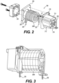
- FIG. 2 illustrates a perspective view, depicting in partially exploded form structures in one example gas humidity conditioning apparatus 200, with an exemplary ambient airflow, in accordance with one or more aspects.
- the gas humidity conditioning apparatus 200 with an exemplary implementation of ambient airflow to humidity transfer tubing, will be referred to as "humidity conditioning apparatus" 200.
- humidity conditioning apparatus 200 can include a housing 212 having sidewalls 214, which can be arranged around and extend parallel to longitudinal axis LX, which will be alternatively referred to as the "winding axis" LX.
- the housing 212 can include an annular end plate 216.
- the annular end plate 216 can have an inner perimeter edge (visible in FIG. 2 but not separately labeled) that can be circumferential around the winding axis LX.
- the annular end plate 216 can also have an outer perimeter edge (visible in FIG. 2 but not separately labeled), which can merge with a peripheral rim (visible in FIG. 2 but not separately labeled) of the housing sidewalls 214.
- the housing sidewalls 214 can extend from the peripheral rim in a direction parallel to the winding axis LX, to an opposite peripheral rim (visible in FIG. 2 but not separately labeled) that merges with a housing end flange 218.
- the peripheral rim of the housing 212 that merges with the housing end flange 218 can define an open end (obstructed from view in FIG. 2 ) of the housing 212.
- merge with carries no limitation as to structure that effects the merging.
- “merged with” can include, without limitation, “connected to,” “attached to,” “fused to” and “molded as respective regions or portions of a single structure.”
- the housing 212 can include a winding support 220 (partially visible in FIG. 2 ) that can extend from the inner perimeter edge of the annular end plate 216, in a direction parallel to the winding axis LX.
- the annular end plate 216 in other words, can support the winding support 220 to extend within the housing sidewalls 214, toward the open end of the housing 212.
- FIGS. 5A and 5B Various structure and functionalities of the winding support 220 are described in greater detail in reference to FIGS. 5A and 5B .
- the gas humidity conditioning apparatus 200 can include a fan 222.
- the fan 222 can be connected to the housing 212 using, for example, an adapter plate 224.
- the fan 222 can include a fan housing (visible in FIG. 2 but not separately numbered) that can be bolted to the adapter plate 224.
- the fan 222 can then be attached to the housing 212 by bolting the adapter plate 224 to the housing end flange 218
- the gas humidity conditioning apparatus 200 can include sample gas tube 226, having a coiled tube section 226V.
- the coiled tube section 226V can be an implementation of the FIG. 1 ambient air ventilated section 126V.
- the coiled tube section 226V can be formed of a permeable material, having a high permeability for water.
- the permeable material can comprise a sulfonated tetrafluoroethylene based fluoropolymer-copolymer.
- the permeable material for example, can be Nafion.
- the sample gas tube 226 can include the tube input end coupled to a tune input coupler 230, and an output end coupled to a tube output coupler 232.
- At least the section of the sample gas tube 226 that forms the coiled tube section 226V can be jacketed by a braided plastic, for example polyester, (not explicitly visible in the figures) to mechanically stabilize and stiffen the material.
- a braided plastic for example polyester
- FIG. 3 illustratively depicts a perspective view of the gas humidity conditioning 200 apparatus, in a construct showing an assembled form, with the housing sidewalls 214 rendered transparent. Referring to FIG. 3 , the arrangement of the coiled tube section 226V of the sample gas tube 226 is partially visible.
- FIG. 4 illustratively depicts another perspective view of the gas humidity conditioning 200 apparatus, in the construct shown in FIG. 3 , with the housing sidewalls 214 not transparent.
- the winding support 220 introduced in reference to FIG. 2 can be hollow, with an opening OP.
- the winding support 220 can also have longitudinal slots 228 and, for each, the annular end plate 216 may provide corresponding cutouts or vents (visible in FIG. 4 but not separately labeled).
- portions of the first starting from the annular end plate 116) three windings of the coiled tube section 226V are visible through three of the longitudinal slots 228, and the corresponding cut-outs or vents formed in the annular end plate 216.
- FIG. 5A illustrates a partial cross-section view of the FIG. 3 and 4 construct, seen from a cut-through plane containing the winding axis LX.
- FIG. 5B illustrates the FIG. 5A partial cross-section view, with its exemplary ventilated coiled tube structure removed, to provide additional view of various structures in accordance with one or more aspects.
- the winding support 220 can be configured to support the coiled tube section coil 226V in a winding configuration having a winding radius R1 from winding axis LX.
- the coiled tube section 226V can be wound around a support surface (not visible in FIG. 3 ) of the winding support 220.
- the support surface of the winding support 220 can be circumferential around and spaced from the winding axis LX by a winding radius R1 or the coiled tube section 226V.
- Inner surfaces 514 (labeled in FIG. 5B ) of the housing sidewalls 214 can be spaced from the coil winding outer surface.
- the inner surfaces of the housing sidewalls 514 and the support surface of the winding support 220 can define an annular volume, which can accommodate the coiled tube section 226V.
- the winding support 220 can have longitudinal slots 228 and, for each of such slots 228, the annular end plate 216 may provide corresponding cutouts or vents (visible in FIG. 4 but not separately labeled).
- a negative pressure may be induced in portions of the annular volume 512 that remain after inclusion of the coiled tube section 226V.
- This pressure can urge ambient airflow AIR-IN to enter that annular volume 512, through the longitudinal slots 228 in the winding support 220, and through corresponding cutouts or vents formed in the annular end plate 216.
- AIR-IN can urge ambient airflow AIR-CH, which flows over and around the coiled tube section 226V, and then out as AIR-EX through the fan 222.
- the combination of the coiled tube section 226V being wound in the annular volume 512, around the winding support 220, which can be hollow with longitudinal slots 228, can maintain the coiled tube section 226V as effectively bathed in the ambient airflow.
- This arrangement in turn, can establish the coiled tube section 226V as a ventilated tube section 226V.
- Benefits and features of the ambient airflow AIR-CH bathing the ventilated tube section 226V can include, for example, prevention or significant retardation of any formation of a skin of dry gas around its outer surface.
- disclosed aspects can deliver a sample gas with acceptable humidity, for at least a range of extremes of humidity, together with extended useful functional life of the tube.
- the structures functioning as the "input air input path" and "air egress path” are only one example.
- the fan 222 can be reversed. The reversal can change the end of the housing proximal to the housing end flange 218 to an "air input path," and can change the longitudinal slots 228, and corresponding cut-outs or vents formed in the annular end plate 216 to an air egress path.
- the fan 222 having its rotational axis collinear and parallel with the winding axis LX is only one example implementation of a fan to urge the described ambient airflow.
- fan 222 can be replaced with a fan rotated 90 degrees (not visible in the figures) from fan 222, in combination with a 90-degree elbow.
- fan 222 can be replaced by a radial fan.
- the gas humidity conditioning apparatus 200 (as well as the apparatus 100) may be used with sample gas from a patient breathing apparatus.
- the ambient air may be approximately 20 degrees C and 30% relative humidity, such as for example in health care facilities based on ANSI/ASHRAE/ASHE standard 170-2008: class B and class C operating rooms, recovery rooms, critical and intensive care rooms, newborn intensive care rooms, patient rooms and/or newborn nursery suites. In such situations and others, improved performance and extended service life may have significant value.
- FIG. 6 illustratively depicts an exemplary flow diagram of an exemplary method for conditioning of sample gas, not part of the invention, using an apparatus as described herein.
- sample gas is received, such as the FIG. 1 inlet 130.
- This sample gas may be taken from a patient breathing gas apparatus, and for example may be from a fitting off an inspiratory limb.
- the sample gas is passed through Nafion tubing, which may be configured with a ventilated coil section, such as the FIG. 1 ventilated coil section 126V or the FIG. 2 ventilated coil section 226V.
- a ventilated coil section such as the FIG. 1 ventilated coil section 126V or the FIG. 2 ventilated coil section 226V.
- ambient airflow contacts and passes over and around the ventilated coil section 126V (or 226V).
- the ambient airflow may be, for example, the FIG. 1 or FIG. 5A AIR-CH, and can be urged by a fan, such as the FIG. 1 fan 120 or the FIG. 2 fan 222.
- a fan such as the FIG. 1 fan 120 or the FIG. 2 fan 222.
- the sample breathing gas passes out of the Nafion tubing, and is analyzed by a gas analyzer such as described herein and below.
- FIG. 7 illustratively depicts some aspects of exemplary implementations of exemplary gas conditioners as described herein, in conjunction with a breathing gas supply apparatus.
- An apparatus 700 is used with a ventilator 710.
- a supply 712 of supplemental or additive gas such as NO provides a supply to conduit 714 and leads to a flow sensor 716 which may also be connected to the ventilator 710.
- other additional breathing materials such as nebulized drugs may be provided into a stream that travels via conduit 720.
- a controller 718 may actuate valves to control, for example, the ratio of NO to the mixture gas in conduit 720.
- a patient inhales the content of conduit 720 which may be considered as an inspiratory limb.
- the patients exhale or excess gas may be considered as an expiratory limb conduit 722. While the sample gas is illustrated in this implementation as being drawn from the inspiratory limb 720, it may be drawn from other parts of the patent breathing apparatus.
- a conduit 724 is in fluid communication with the inspiratory limb and may be referred to as a sample gas line.
- a filter trap 726 receives some or all of the sample gas. This filter trap 726 may correspond to a filter assembly that removes water and/or particulates from the sample gas.
- the gas is passed to a gas conditioner apparatus labeled 740.
- the gas conditioner apparatus 740 can be, for example the humidity conditioning apparatus 100 described in reference to FIG. 1 , or the gas sample humidity conditioning apparatus 200 described in reference to FIGS. 2-5B .
- the now humidity-conditioned sample gas can pass to a gas sampling system 728, and may exhaust via exhaust outlet 730.
- the controller 718 may control some operations of the conditioner apparatus (100, 200, 740) such as by way of example only, the fan speed thereof.
- any of the steps described can be rearranged, separated, and/or combined without deviating from the scope of the invention.
- steps are, at times, presented sequentially. This is merely for ease and is in no way meant to be a limitation.
- any of the elements and/or embodiments of the invention described can be rearranged, separated, and/or combined without deviating from the scope of the invention.
- various elements are described, at times, separately. This is merely for ease and is in no way meant to be a limitation.
Landscapes
- Health & Medical Sciences (AREA)
- Life Sciences & Earth Sciences (AREA)
- Engineering & Computer Science (AREA)
- General Health & Medical Sciences (AREA)
- Chemical & Material Sciences (AREA)
- Veterinary Medicine (AREA)
- Public Health (AREA)
- Animal Behavior & Ethology (AREA)
- Heart & Thoracic Surgery (AREA)
- Biomedical Technology (AREA)
- Pulmonology (AREA)
- Emergency Medicine (AREA)
- Hematology (AREA)
- Anesthesiology (AREA)
- Physics & Mathematics (AREA)
- Pathology (AREA)
- Analytical Chemistry (AREA)
- Medicinal Chemistry (AREA)
- Chemical Kinetics & Catalysis (AREA)
- Biophysics (AREA)
- Molecular Biology (AREA)
- General Physics & Mathematics (AREA)
- Immunology (AREA)
- Biochemistry (AREA)
- Food Science & Technology (AREA)
- Pharmacology & Pharmacy (AREA)
- Surgery (AREA)
- Physiology (AREA)
- Medical Informatics (AREA)
- Combustion & Propulsion (AREA)
- Oil, Petroleum & Natural Gas (AREA)
- General Chemical & Material Sciences (AREA)
- Inorganic Chemistry (AREA)
- Epidemiology (AREA)
- Bioinformatics & Cheminformatics (AREA)
- Sampling And Sample Adjustment (AREA)
- Respiratory Apparatuses And Protective Means (AREA)
- Air Humidification (AREA)
Description
- The present disclosure generally relates to the humidity conditioning of sample gas affiliated with a ventilator and/or nitric oxide delivery system.
-
EP2878327A1 describes an apparatus for inhalation of medicine, in which particles in a medicinal aqueous solution, in a liquid aerosol form, are converted to dry medicinal particles by removing moisture therefrom by means of an evaporation unit.EP1695731A1 discloses a humidifying device for humidifying a gas.US4825863A describes a portable unit for combatting hypothermia.WO2015/167347A1 describes a humidification arrangement that can be configured to have multiple compartments. - Many patients benefit from receiving therapeutic gas (e.g., nitric oxide gas) in inspiratory breathing gas flow from a breathing circuit affiliated with a ventilator. The ventilator can be, for example, a constant flow ventilator, variable flow ventilator, high frequency ventilator, bi-level positive airway pressure ventilator or BiPAP ventilator, etc.). To provide therapeutic gas to the patient, the therapeutic gas may be injected into the inspiratory breathing gas flowing in the breathing circuit. This inhaled therapeutic gas is often provided via a therapeutic gas delivery system as a constant concentration, which is provided based on proportional delivery of the therapeutic gas to the breathing gas. Further, a sampling system (e.g., affiliated with the therapeutic gas delivery system) may continuously draw in the inspiratory breathing gas flow to at least confirm that the desired dose of the therapeutic gas in the inspiratory breathing gas flow is being delivered to the patient. For example, a sample pump may pull in inspiratory flow (e.g., in the vicinity of the patient) to confirm that the desired therapeutic gas concentration is in fact being delivered to the patient in need thereof.
- One such therapeutic gas is inhaled nitric oxide (iNO). In many instances iNO is used as a therapeutic gas to produce vasodilatory effect on patients. When inhaled, NO acts to dilate blood vessels in the lungs, improving oxygenation of the blood and reducing pulmonary hypertension. Because of this, nitric oxide is provided in inspiratory breathing gases for patients with various pulmonary pathologies including hypoxic respiratory failure (HRF) and persistent pulmonary hypertension (PPH). The actual administration of iNO is generally carried out by its introduction into the patient as a gas along with other normal inhalation gases, for example, by introducing iNO, from an iNO delivery system, into the inspiratory flow of a patient breathing circuit affiliated with a ventilator.
- Separately and/or in conjunction with iNO, patients may receive inspiratory breathing gas flow containing liquid particles (e.g., moisture from humidified air, etc.) and/or other particles. Although this matter in the inspiratory breathing flow may provide additional benefit to the patient, it may interfere with or degrade operation of the sample gas analyzer. For example, the sample gas analyzer itself may work best when it receives sample gas within a given humidity range, and liquid particles as described above may be inconsistent with that range.
- One known technique directed at keeping the sample gas at a desired humidity is to use, as part of the pathway of the sample gas before it arrives at the analyzer, a tubing formed of a sulfonated tetrafluoroethylene based fluoropolymer-copolymer, for example, the commercially available Nafion® tubing. Properties of such tubing include a permeability that is very selective to water and that provides rapid transfer through the tubing walls. Provided that the permeability is maintained, such tubing can provide a mechanism operating as follows: if the humidity level of the sample gas passing through the tubing exceeds an acceptable maximum (and assumedly above ambient), some of that excess humidity will permeate out through the tube walls before the sample gas reaches the analyzer. Conversely, if the humidity level of the sample gas passing through the tubing is below the acceptable minimum (and assumedly below ambient), some of the ambient humidity will permeate in through the tube walls and raise the humidity of the sample gas to be within an acceptable range, prior to reaching the analyzer.
- However, a conventional arrangement of Nafion tubing can form, over time, a dry external layer, i.e., at its outer wall surface, or dry inner layer at its passage wall surfaces, or both. With subscribing to any particular scientific theory, the inventor believes the mechanism of the drying may be a dehydration of the aqueous sulfonic acid inherent to the Nafion construction. Such dry layers can effectively become an obstruction to the above-described humidity conditioning function. This drying and obstructing layer formation can significantly shorten the operational life of Nafion (and equivalent) tubing type humidity conditioners.
- Accordingly, there is a need for a humidity conditioner having the performance that can be obtained with Nafion and, concurrently, a significantly longer operational life than provided by conventional technique Nafion humidity conditioners.
- The invention is defined in the appended claims.
- Aspects of the present disclosure generally relate to apparatuses directed to enhanced performance and extended equipment life in humidity conditioning of sample gas. More specifically some implementations relate to enhancing or controlling the humidity of sample gas affiliated with a ventilator and/or nitric oxide delivery system. Further, some implementations relate to the humidity of sample gas prior to being analyzed by a gas analyzer. Further, some implementations relate to humidity conditioning a sample gas, using Nafion tubing, by passing ambient air over the tubing using a fan or other forced air device. The tubing may be in the form of a coil housed in a housing, with a fan forcing (or blowing) air over the tubing.
- Disclosed aspects include a sample gas conditioning apparatus, and the apparatus includes a housing, at least partially defining a chamber, and at least partially defining an air input path into the chamber and an air egress path from the chamber. The sample gas conditioning apparatus includes a fan, connected to the housing, and configured to urge an ambient air flow through the chamber, the ambient air flow entering through the air input path into the chamber, and exiting the chamber through the air egress path. The sample gas conditioning apparatus includes a sample gas tube having a section that comprises a permeable material. The section is arranged and supported in the chamber in a configuration wherein at least a portion of the section is a ventilated section, ventilated by the ambient air flow through the chamber.
- Disclosed embodiments also include structure for arranging and supporting the ventilated section in the chamber in a configuration, relative to the ambient air flow through the chamber, that establishes flow parameters of the ambient air flow, in regions adjacent to outer surfaces of the ventilated section, at levels that prevent or significantly retard formation of a skin of dry gas around the outer surface of the ventilated section.
- The sample gas tube has an input end and an output end, and can include the section comprising permeable material providing a passage distance for the sample gas, wherein the passage distance in combination with a flow rate of the sample gas provides, for at least a range of humidity level of sample gas at the input end that is outside of a given acceptable range, a conditioning of the sample gas as it travels the passage distance wherein, at the output end, the humidity level is within the given acceptable range. Disclosed embodiments include, but are not limited to, an acceptable range that extends from approximately 15% relative humidity to approximately 90% relative humidity.
- Disclosed embodiments include the sample gas tube having an input and an output, and the apparatus can further comprise a connection of the input to a conduit, the conduit being configured to deliver a mixture of a mixture gas and a therapeutic gas to a patient. The sample gas tube can be configured to provide passage of a sample of the mixture of the mixture gas and the therapeutic gas to the ventilated section, and to output, at the output, a humidity conditioned sample of the mixture of the mixture gas and the therapeutic gas. The therapeutic gas comprises nitric oxide, which may be inhaled nitric oxide.
- The fan may be connected to the housing, in an alignment with the air egress path, and in a configuration that urges a negative pressure in the chamber. The negative pressure can effect an urging of the ambient airflow through the airflow input to the chamber, out through the air egress path, and into the fan.
- Disclosed embodiments include the water permeable material comprising a sulfonated tetrafluoroethane based fluoropolymer-copolymer, and include the water permeable material comprising Nafion.
- Disclosed embodiments also include the tube walls of the ventilated section providing a tubular membrane, formed of the permeable material, and the permeable material transferring water through the tubular membrane, based on First Order Kinetic reaction. In addition, disclosed embodiments include the tubular membrane having a start and having an end, and providing a passage length from the start to the end, wherein based at least in part on the passage length the tubular membrane provides, for at least a range of humidity level of the sample gas at the start that is outside of a given acceptable range, a humidity level of the sample gas at the end that is within the given acceptable range.
- Disclosed embodiments include the ventilated section being a coiled tube section, with windings around a winding axis. Disclosed embodiments include the coiled section having a winding turn and, in another aspect, having at least two winding turns.
- Disclosed embodiments also include a configuration of the air input path, the air egress path, and inner wall surfaces of the housing, relative to the coiled section, that urges the ambient airflow through the chamber according to a flow direction, the flow direction being generally parallel to the winding axis. In addition, disclosed embodiments include the winding turns forming a coil winding outer surface, the coil winding outer surface being radially distal from the winding axis, and the chamber being defined, at least in part, by an inner surface of the housing that extends a length along the winding axis and, circumferentially around the winding axis, faces toward the winding axis.
- Disclosed embodiments include the housing having a housing cap, having a cap perimeter, and that the housing having housing sidewalls that extend, parallel to the winding axis, from the cap perimeter to a housing open end. In addition, disclosed embodiments include the housing sidewalls forming sidewall inner surfaces that can face and have a clearance from the coil winding outer surface. Disclosed embodiments also include the housing being configured to provide the air egress path as at least a portion of the housing open end area. In addition, disclosed aspects include the housing cap being a vented housing cap, providing a vent into the chamber, and the air inlet path as comprising the vent.
- Disclosed embodiments include the fan as comprising an electric motor, that can be supported in a fan housing, and a rotor shaft and a rotary fan blade attached to the rotor shaft. In addition, disclosed aspects include the housing being configured with a housing mounting flange at the housing open end, and that the fan housing can be secured to the housing mounting flange, in a configuration where the rotor shaft can be parallel to the winding axis.
- Also, disclosed embodiments include the fan housing being secured to the mounting flange by an adapter plate, the adapter plate having an adapter plate first face and, opposite and parallel to the adapter plate first face, an adapter plate second face. Described exemplary implementations according to this disclosed aspect include the fan housing being secured, by fan housing mount bolts, to the adapter plate first face, in combination with the housing mounting flange being secured, by housing mount bolts, to the adapter plate second face.
- Disclosed examples include providing a method, not part of the invention, for verifying therapeutic gas for delivery to a patient, and exemplary operations can include adding a therapeutic gas as a supplement to a mixture gas, and delivering to the patient, though a conduit, the mixture gas supplemented with the therapeutic gas is delivered. In an example, operations can include receiving a gas sample from the conduit, through a gas sample line, of the mixture gas supplemented with the therapeutic gas. Disclosed examples include humidity conditioning the sample gas, by passing the sample gas through a water-permeable tubular membrane, wherein the sample gas leaving the water-permeable tubular membrane is a humidity conditioned sample gas, and analyzing the humidity conditioned sample gas to determine a mixing ratio. Disclosed examples include, concurrent with passing the sample gas through the water-permeable tubular membrane, maintaining a section of the water permeable tubular membrane as a ventilated water permeable tubular membrane, by operations that include exposing outer surfaces of the ventilated water permeable tubular membrane to an ambient air flow.
- The therapeutic gas can comprise inhaled nitric oxide. Operations in passing the sample gas through the water-permeable tubular membrane can comprise passing the sample gas through a tubular membrane formed of a sulfonated tetrafluoroethylene based fluoropolymer-copolymer. Operations in passing the sample gas through the water-permeable tubular membrane can comprise passing the sample gas through a tubular membrane formed of Nafion.
- Disclosed examples include providing a method, not part of the invention, directed to humidity conditioning a sample gas, and operations can include passing the sample gas through a water-permeable tubular membrane and, concurrent with passing the sample gas through the water-permeable tubular membrane, establishing a section of the water permeable tubular membrane as a ventilated water permeable tubular membrane, by exposing outer surfaces of the ventilated water permeable tubular membrane to an ambient air flow.
- Disclosed embodiments include, in addition, exposing outer surfaces of the ventilated water permeable tubular membrane to the ambient air flow to provide the ambient airflow with characteristics that can prevent or significantly retard formation of a skin of dry gas around the outer surfaces of the ventilated water permeable tubular membrane.
- Also, disclosed embodiments include establishing the ventilated water permeable tubular membrane to have a start and an end, and a passage length between the start and the end. Disclosed embodiments include the passage length being such that the water permeable tubular membrane provides, for at least a range of humidity level at the start that is outside of a given acceptable range, a humidity of the sample gas at the end within the given acceptable range.
- Other features, examples and aspects of the disclosure will be apparent from the following detailed description, the drawings, and the claims.
- The features and advantages of the present disclosure will be more fully understood with reference to the following, detailed description when taken in conjunction with the accompanying figures, wherein:
-
FIG. 1 schematically depicts a gas humidity conditioning apparatus, with an exemplary ambient airflow to humidity transfer tubing, in accordance with one or more aspects; -
FIG. 2 illustrates a perspective view, depicting in partially exploded form structures in an example gas humidity conditioning apparatus, with an exemplary implementation of ambient airflow to humidity transfer tubing, according to one or more aspects; -
FIG. 3 illustratively depicts a perspective view of theFIG. 2 apparatus, in a construct showing an assembled form; -
FIG. 4 illustratively depicts another perspective view of theFIG. 2 apparatus, according to theFIG. 3 construct; -
FIG. 5A illustrates a partial cross-sectional view of the construct ofFIGS 2 and 3 , cut down a centerline thereof; -
FIG. 5B illustrates theFIG. 5A partial cross-section view, with its exemplary ventilated coiled tube structure removed, to provide additional view of various structures in accordance with one or more aspects; -
FIG. 6 illustratively depicts one flow diagram, representing example operations in a method, not part of the invention, directed to humidity conditioning and to extending humidity conditioning tube life, and to other features, in accordance with various aspect; and -
FIG. 7 illustratively depicts at least some aspects of implementation of a Nafion tubing enhancing apparatus, in conjunction with a breathing gas supply apparatus, in accordance with various exemplary aspects of the present disclosure. - Generally, aspects of the present disclosure relate to apparatuses and methods to enhance the humidity conditioning of sample gas. More specifically, some implementations relate to enhancing or controlling the humidity of sample gas affiliated with a ventilator and/or nitric oxide delivery system. Further, some implementations relate to the humidity of sample gas prior to its being analyzed by a gas analyzer. Further, some implementations relate to humidity conditioning the sample gas by passing it through a length of Nafion or alternative water permeable tubing and, concurrently, passing ambient air over the tubing using a fan or other forced air device.
- Various examples in the present disclosure refer to Nafion tubing. Reasons include Nafion being a material that is known in the art. Other reasons include the problems to which this application is directed being known to manifest when Nafion is used for humidity conditioning a sample gas. However, references to Nafion are not intended to limit disclosed systems and methods to Nafion tubing.
- For convenience in description, the arbitrary term "selective high permeability material" is hereby introduced and will be introduced to mean: material, including but not limited to sulfonated tetrafluoroethylene based fluoropolymer-copolymer, including Nafion, and reasonable equivalents thereto, that exhibits selective, high water permeability, the selectivity and permeability being acceptable for humidifying/de-humidifying sample gas in therapeutic gas delivery systems and having suitable chemical resistance to enable use in therapeutic gas delivery systems. It will also be understood that, except where explicitly stated or made clear from its context to mean otherwise, that the term "Nafion" means: "Nafion or other selective high permeability material."
- One sample gas conditioning apparatus according to one or more aspects can include a housing, configured to at least partially define a chamber, and to form, or at least partially define an air input path into the chamber and an air egress path from the chamber. An example sample gas conditioning apparatus according to one or more aspects can also include a fan, connected to the housing, in a configuration such that action of the fan urges an ambient air flow through the chamber, the ambient air flow entering through the air input path into the chamber, and exiting the chamber through the air egress path. An example sample gas conditioning apparatus according to one or more aspects can also include a sample gas tube, having a section that comprises a permeable material. The permeable material can be, for example, Nafion. In an aspect at least a portion of the section can be arranged in the chamber as a ventilated section, the ventilated section being ventilated by the ambient airflow through the chamber. In an aspect, the ventilated section can include a coiled tube section. The coiled tube section can comprise, for example, a winding turn, or least two winding turns, or any integer plurality of winding turns, with or without supplement by partial turns. In an aspect, the winding turns of the coiled tube section can be around a winding axis. In a further aspect, the air input path, air egress path, and the housing can have a joint configuration that urges the ambient air flow through the chamber to have a flow direction, the flow direction being generally parallel to the winding axis. However, in other implementations the tube section may have a coil or winding arrangement that has turns that are other than circular.
- It will be understood that in described implementations that include an air input path and flow though the chamber to an air egress path, the structures functioning as the "input air input path" and "air egress path" are only one example. In one alternative implementation, the described fan direction can be reversed, whereupon structure described as input air input path will be the air egress path, and structure described as the air egress path will be the air input path.
- In an aspect "sample gas," as used herein, can be a sample gas drawn from a delivered therapeutic gas in the context of delivery of therapeutic gas to patients (e.g., patients receiving breathing gas, with therapeutic gas, from a ventilator circuit). The sample gas, for example, may be removed from an inspiratory limb of a therapeutic gas delivery system to be monitored by a sampling device. Applications can include a filtering of the sample gas prior to being humidity conditioned according to disclosed concepts. Humidity conditioning of sample gas according to disclosed concepts, applied to therapeutic delivery systems may, for example, allow improved accuracy in monitoring what is delivered. Such accuracy can provide improved confirmation of dosing (e.g., nitric oxide concentration, etc.) as well as other parameters (e.g., nitrogen dioxide concentration, oxygen concentration, etc.). As an additional benefit, humidity conditioning of sample gas according to disclosed concepts can provide significantly extended service life of the humidity conditioning tubing. This can reduce costs and make continuous monitoring more feasible.
-
FIG. 1 shows, in a cross-sectional view, a samplegas conditioning apparatus 100 according to various aspects. - Referring to
FIG. 1 ,apparatus 100 can include ahousing 112, which can be configured to at least partially define achamber 114. Thehousing 112 can include acap 112C, and sidewalls 112S. Thecap 112C can be integral to thehousing 112. Alternatively, thecap 112C can be secured, by adhesive or other means, to a region of the sidewalls 112S. In an aspect, thesidewalls 112S can extend from thecap 112C (right-to-left in the image plane ofFIG. 1 ) to form a housing open-end, identified by theFIG. 1 dotted line labeled 116. - With continuing reference to
FIG. 1 , thehousing 112 may include, for example, a vent 118, as an air input path to thechamber 114. It will be understood that "vent" and "air input path" are not limited to being a single passage. In an aspect, the housingopen end 116 can function, for example, as described in greater detail later, as an air passage, opening and/or egress from thechamber 114. - Referring to
FIG. 1 , in an aspect, theapparatus 100 can include afan 120, which, according to one aspect, can be connected or mounted to thehousing 112. Thefan 120 may be connected or mounted, for example, in alignment with, or in another cooperative arrangement with the housingopen end 116. Thefan 120 can be, for example, an off-the-shelf device, such as readily available from various vendors. Thefan 120 can include a frame orhousing 122, which is partially visible in theFIG. 1 cross-sectional view. The frame orhousing 122 can support a motor-driven rotary fan blade (visible in part but not separately numbered). In one example, thefan 120 can urge an ambient airflow in a direction that, in theFIG. 1 image plane, appears as right-to-left. Accordingly the side of thefan 120 facing toward the housingopen end 116 can be termed a "fan input," and the opposite side can be termed a "fan output." - Capacity (e.g., volume per unit time) and electrical power requirements for the
fan 120, e.g., voltage and whether AC or DC, are application-specific. Persons of ordinary skill having possession of this disclosure can readily select and implement thefan 120 without undue experimentation. - Upon receiving power, the
fan 120 can urge an ambient airflow that can enter thechamber 114 through the air input, e.g., thevent 106, continue through thechamber 114, and exit from the housingopen end 116.FIG. 1 labels an example of this ambient airflow according to regions, with "AIR-IN" labeling the ambient airflow entering thechamber 114 through the air input, e.g., thevent 106, "AIR-CH" labeling ambient airflow through thechamber 114, and "AIR-EX" labeling ambient airflow exiting thechamber 114 through the housingopen end 116. - Continuing to refer to
FIG. 1 thesystem 100 can include asample gas tube 126, having an input end (visible inFIG. 1 but not separately numbered) coupled to atube input coupler 130, and an output end (visible inFIG. 1 but not separately numbered) coupled to atube output coupler 128. In an aspect, the entire length of thesample gas tube 126, from the input end to the output end, can be formed of Nafion or another selective high permeability material. In one alternative, at least the portion labeled "126V," which will be described as the "ambient air ventilatedsection 126V," can be formed of Nafion or another selective high permeability material. The example ofFIG. 1 may be considered a parallel flow configuration. If the input coupler and output coupler are reversed, as can be the case in some implementations, then the arrangement may be considered a counter-flow arrangement. - In an aspect, the ventilated
section 126V can be arranged to be within the ambient airflow AIR-CH. In an arrangement such as illustrated inFIG. 1 , the ambient air ventilatedsection 126V is effectively bathed in the ambient airflow. It will be understood that "within the airflow," in the context of "within the ambient airflow AIR-CH," means exposure to the ambient airflow AIR-CH sufficient to prevent or significantly retard formation of a skin of dry gas around the outer surface of the ambient air ventilatedsection 126V. - Referring to
FIG. 1 , the ambient air ventilatedsection 126V can be configured to include a "coiled tube section" (visible inFIG. 1 , but not separately numbered). The coiled tube section can comprise, for example, a winding turn (visible inFIG. 1 , but not separately labeled), or any number of winding turns, such the example two (2) winding turns that are visible inFIG. 1 . In an aspect, the winding turns of the coiled tube section can be wound around a winding axis, such as the winding axis AX. Further aspects of supporting the coiled tube section within thehousing 112 are described in reference toFIGS. 2-5B . - In an aspect, at least the section of the
sample gas tube 126 that forms the ambientair tube section 126V can be jacketed by a braided plastic, for example polyester, (not explicitly visible in the figures) to mechanically stabilize and stiffen the material. - Benefits of forming the ambient air ventilated
section 126V as a coiled tube section include, for example, providing a greater passage length within a smaller volume. This can provide, among various benefits, a smaller requiredchamber 114, i.e.,smaller housing 112. Another example benefit can be a smaller total flow volume for the ambient airflow AIR-CH. - Regarding the physical length of the ambient air ventilated
section 126V, this can be determined, without undue experimentation, by a person of ordinary skill having possession of this disclosure. For example, in various applications, all of the following can be established, ascertained, or given up front: i) the water permeability of the tube walls; ii) the rate of the sample gas (or other gas to be conditioned); iii) the expected range of humidity of the received sample gas (or of the other gas to be conditioned); and iv) the acceptable range for the humidity of the conditioned gas. Identifying all of (i) through (iv), for a given application, can be readily performed by persons of ordinary skill in the art. Therefore, further detailed description is omitted. Upon (i) through (iv), being identified, the physical length of the ambient air ventilatedsection 126V can be readily determined, for example, by the following guideline in view of this entire disclosure: calculate (or find through simulation) a physical length such that the gas, after traveling that length, will have humidity that has been raised or lowered (from the maximum and minimum extremes of the input humidity range), to within the acceptable range. -
FIG. 2 illustrates a perspective view, depicting in partially exploded form structures in one example gashumidity conditioning apparatus 200, with an exemplary ambient airflow, in accordance with one or more aspects. The gashumidity conditioning apparatus 200, with an exemplary implementation of ambient airflow to humidity transfer tubing, will be referred to as "humidity conditioning apparatus" 200. - Referring to
FIG. 2 ,humidity conditioning apparatus 200 can include ahousing 212 havingsidewalls 214, which can be arranged around and extend parallel to longitudinal axis LX, which will be alternatively referred to as the "winding axis" LX. In an aspect, thehousing 212 can include anannular end plate 216. Theannular end plate 216 can have an inner perimeter edge (visible inFIG. 2 but not separately labeled) that can be circumferential around the winding axis LX. Theannular end plate 216 can also have an outer perimeter edge (visible inFIG. 2 but not separately labeled), which can merge with a peripheral rim (visible inFIG. 2 but not separately labeled) of thehousing sidewalls 214. Thehousing sidewalls 214 can extend from the peripheral rim in a direction parallel to the winding axis LX, to an opposite peripheral rim (visible inFIG. 2 but not separately labeled) that merges with ahousing end flange 218. The peripheral rim of thehousing 212 that merges with thehousing end flange 218 can define an open end (obstructed from view inFIG. 2 ) of thehousing 212. - It will be understood that "merge with," as used in this disclosure, carries no limitation as to structure that effects the merging. For example, "merged with" can include, without limitation, "connected to," "attached to," "fused to" and "molded as respective regions or portions of a single structure."
- Continuing to refer to
FIG. 2 , in an aspect, thehousing 212 can include a winding support 220 (partially visible inFIG. 2 ) that can extend from the inner perimeter edge of theannular end plate 216, in a direction parallel to the winding axis LX. Theannular end plate 216, in other words, can support the windingsupport 220 to extend within thehousing sidewalls 214, toward the open end of thehousing 212. Various structure and functionalities of the windingsupport 220 are described in greater detail in reference toFIGS. 5A and 5B . - Continuing to refer to
FIG. 2 , in an aspect, the gashumidity conditioning apparatus 200 can include afan 222. Thefan 222 can be connected to thehousing 212 using, for example, anadapter plate 224. Thefan 222 can include a fan housing (visible inFIG. 2 but not separately numbered) that can be bolted to theadapter plate 224. Thefan 222 can then be attached to thehousing 212 by bolting theadapter plate 224 to thehousing end flange 218 - In an aspect, the gas
humidity conditioning apparatus 200 can includesample gas tube 226, having a coiledtube section 226V. The coiledtube section 226V can be an implementation of theFIG. 1 ambient air ventilatedsection 126V. In an aspect, the coiledtube section 226V can be formed of a permeable material, having a high permeability for water. In an implementation, the permeable material can comprise a sulfonated tetrafluoroethylene based fluoropolymer-copolymer. The permeable material, for example, can be Nafion. Thesample gas tube 226 can include the tube input end coupled to atune input coupler 230, and an output end coupled to atube output coupler 232. - In an aspect, at least the section of the
sample gas tube 226 that forms the coiledtube section 226V can be jacketed by a braided plastic, for example polyester, (not explicitly visible in the figures) to mechanically stabilize and stiffen the material. -
FIG. 3 illustratively depicts a perspective view of thegas humidity conditioning 200 apparatus, in a construct showing an assembled form, with thehousing sidewalls 214 rendered transparent. Referring toFIG. 3 , the arrangement of the coiledtube section 226V of thesample gas tube 226 is partially visible. -
FIG. 4 illustratively depicts another perspective view of thegas humidity conditioning 200 apparatus, in the construct shown inFIG. 3 , with thehousing sidewalls 214 not transparent. Referring toFIG. 4 , in an aspect, the windingsupport 220 introduced in reference toFIG. 2 can be hollow, with an opening OP. The windingsupport 220 can also havelongitudinal slots 228 and, for each, theannular end plate 216 may provide corresponding cutouts or vents (visible inFIG. 4 but not separately labeled). Referring toFIG 4 , portions of the first (starting from the annular end plate 116) three windings of the coiledtube section 226V are visible through three of thelongitudinal slots 228, and the corresponding cut-outs or vents formed in theannular end plate 216. -
FIG. 5A illustrates a partial cross-section view of theFIG. 3 and4 construct, seen from a cut-through plane containing the winding axis LX.FIG. 5B illustrates theFIG. 5A partial cross-section view, with its exemplary ventilated coiled tube structure removed, to provide additional view of various structures in accordance with one or more aspects. - Referring to
FIGS. 5A and 5B , the windingsupport 220 can be configured to support the coiledtube section coil 226V in a winding configuration having a winding radius R1 from winding axis LX. The coiledtube section 226V can be wound around a support surface (not visible inFIG. 3 ) of the windingsupport 220. The support surface of the windingsupport 220 can be circumferential around and spaced from the winding axis LX by a winding radius R1 or the coiledtube section 226V. Inner surfaces 514 (labeled inFIG. 5B ) of thehousing sidewalls 214 can be spaced from the coil winding outer surface. The inner surfaces of thehousing sidewalls 514 and the support surface of the windingsupport 220 can define an annular volume, which can accommodate the coiledtube section 226V. - As identified in reference to
FIG. 4 , and as further visible inFIGS. 5A and 5B , the windingsupport 220 can havelongitudinal slots 228 and, for each ofsuch slots 228, theannular end plate 216 may provide corresponding cutouts or vents (visible inFIG. 4 but not separately labeled). - Referring to
FIGS. 4 ,5A and 5B , example operations of the gashumidity conditioning apparatus 200 according to various aspects will now be described. Upon powering thefan 222, a negative pressure may be induced in portions of theannular volume 512 that remain after inclusion of the coiledtube section 226V. This pressure can urge ambient airflow AIR-IN to enter thatannular volume 512, through thelongitudinal slots 228 in the windingsupport 220, and through corresponding cutouts or vents formed in theannular end plate 216. AIR-IN can urge ambient airflow AIR-CH, which flows over and around the coiledtube section 226V, and then out as AIR-EX through thefan 222. - It will be understood that the combination of the coiled
tube section 226V being wound in theannular volume 512, around the windingsupport 220, which can be hollow withlongitudinal slots 228, can maintain the coiledtube section 226V as effectively bathed in the ambient airflow. In an aspect, an outer texture of thesample gas tube 226 forming the coiled tube section. This arrangement, in turn, can establish the coiledtube section 226V as a ventilatedtube section 226V. Benefits and features of the ambient airflow AIR-CH bathing the ventilatedtube section 226V can include, for example, prevention or significant retardation of any formation of a skin of dry gas around its outer surface. In addition, based in part on the aspect of providing a multiple turn coiled (hence longer) ventilated tube, disclosed aspects can deliver a sample gas with acceptable humidity, for at least a range of extremes of humidity, together with extended useful functional life of the tube. - In the above-described implementations with an air input path and flow though the chamber to an air egress path, the structures functioning as the "input air input path" and "air egress path" are only one example. For example, referring to
FIG. 4 , in thehumidity conditioning apparatus 200 thefan 222 can be reversed. The reversal can change the end of the housing proximal to thehousing end flange 218 to an "air input path," and can change thelongitudinal slots 228, and corresponding cut-outs or vents formed in theannular end plate 216 to an air egress path. In addition, thefan 222 having its rotational axis collinear and parallel with the winding axis LX is only one example implementation of a fan to urge the described ambient airflow. In one alternative implementation,fan 222 can be replaced with a fan rotated 90 degrees (not visible in the figures) fromfan 222, in combination with a 90-degree elbow. In another alternative implementation,fan 222 can be replaced by a radial fan. - According to various aspects, the gas humidity conditioning apparatus 200 (as well as the apparatus 100) may be used with sample gas from a patient breathing apparatus. In some cases the ambient air may be approximately 20 degrees C and 30% relative humidity, such as for example in health care facilities based on ANSI/ASHRAE/ASHE standard 170-2008: class B and class C operating rooms, recovery rooms, critical and intensive care rooms, newborn intensive care rooms, patient rooms and/or newborn nursery suites. In such situations and others, improved performance and extended service life may have significant value.
-
FIG. 6 illustratively depicts an exemplary flow diagram of an exemplary method for conditioning of sample gas, not part of the invention, using an apparatus as described herein. Atprocess 610, sample gas is received, such as theFIG. 1 inlet 130. This sample gas may be taken from a patient breathing gas apparatus, and for example may be from a fitting off an inspiratory limb. Atprocess 612a, the sample gas is passed through Nafion tubing, which may be configured with a ventilated coil section, such as theFIG. 1 ventilatedcoil section 126V or theFIG. 2 ventilatedcoil section 226V. Concurrently withprocess 612a, atprocess 612b ambient airflow contacts and passes over and around the ventilatedcoil section 126V (or 226V). The ambient airflow may be, for example, theFIG. 1 orFIG. 5A AIR-CH, and can be urged by a fan, such as theFIG. 1 fan 120 or theFIG. 2 fan 222. Atprocess 614, the sample breathing gas passes out of the Nafion tubing, and is analyzed by a gas analyzer such as described herein and below. -
FIG. 7 illustratively depicts some aspects of exemplary implementations of exemplary gas conditioners as described herein, in conjunction with a breathing gas supply apparatus. Anapparatus 700 is used with aventilator 710. Asupply 712 of supplemental or additive gas such as NO provides a supply toconduit 714 and leads to aflow sensor 716 which may also be connected to theventilator 710. At any stage of breathing gas supply, other additional breathing materials such as nebulized drugs may be provided into a stream that travels viaconduit 720. Acontroller 718 may actuate valves to control, for example, the ratio of NO to the mixture gas inconduit 720. A patient inhales the content ofconduit 720 which may be considered as an inspiratory limb. The patients exhale or excess gas may be considered as anexpiratory limb conduit 722. While the sample gas is illustrated in this implementation as being drawn from theinspiratory limb 720, it may be drawn from other parts of the patent breathing apparatus. - In this example, a
conduit 724 is in fluid communication with the inspiratory limb and may be referred to as a sample gas line. Afilter trap 726 receives some or all of the sample gas. Thisfilter trap 726 may correspond to a filter assembly that removes water and/or particulates from the sample gas. After being filtered by thefilter trap 726, the gas is passed to a gas conditioner apparatus labeled 740. In an aspect, thegas conditioner apparatus 740 can be, for example thehumidity conditioning apparatus 100 described in reference toFIG. 1 , or the gas samplehumidity conditioning apparatus 200 described in reference toFIGS. 2-5B . After leaving thegas conditioner apparatus 740, the now humidity-conditioned sample gas can pass to agas sampling system 728, and may exhaust viaexhaust outlet 730. In some implementations, thecontroller 718 may control some operations of the conditioner apparatus (100, 200, 740) such as by way of example only, the fan speed thereof. - The foregoing detailed descriptions are presented to enable any person skilled in the art to make and use the disclosed subject matter. For purposes of explanation, specific nomenclature is set forth to provide a thorough understanding. However, it will be apparent to one skilled in the art that these specific details are not required to practice the disclosed subject matter. Descriptions of specific applications are provided only as representative examples. Various modifications to the disclosed implementations will be readily apparent to one skilled in the art, and the general principles defined herein may be applied to other implementations and applications without departing from the scope of this disclosure. The sequences of operations described herein are merely examples, and the sequences of operations are not limited to those set forth herein, but may be changed as will be apparent to one of ordinary skill in the art, with the exception of operations necessarily occurring in a certain order. Also, description of functions and constructions that are well known to one of ordinary skill may be omitted for increased clarity and conciseness. This disclosure is not intended to be limited to the implementations shown, but is to be accorded the widest possible scope consistent with the principles and features disclosed herein.
- It will be apparent to those skilled in the art that various modifications and variations can be made to the methods and systems of the present description without departing from the scope of the description. Thus, it is intended that the present description include modifications and variations that are within the scope of the appended claims and their equivalents.
- It will be understood that any of the steps described can be rearranged, separated, and/or combined without deviating from the scope of the invention. For ease, steps are, at times, presented sequentially. This is merely for ease and is in no way meant to be a limitation. Further, it will be understood that any of the elements and/or embodiments of the invention described can be rearranged, separated, and/or combined without deviating from the scope of the invention. For ease, various elements are described, at times, separately. This is merely for ease and is in no way meant to be a limitation.
- The separation of various system components in the examples described above should not be understood as requiring such separation in all examples, and it should be understood that the described components and systems can generally be integrated together in a single package into multiple systems and/or multiple components. It is understood that various modifications may be made therein and that the subject matter disclosed herein may be implemented in various forms and examples, and that the teachings may be applied in numerous applications, only some of which have been described herein. Unless otherwise stated, all measurements, values, ratings, positions, magnitudes, sizes, and other specifications that are set forth in this specification, including in the claims that follow, are approximate, not exact. They are intended to have a reasonable range that is consistent with the functions to which they relate and with what is customary in the art to which they pertain.
- Although the invention herein has been described with reference to particular implementations, it is to be understood that these are merely illustrative, to further assist persons of ordinary skill in understanding the present concepts to make and use embodiments thereof. It will also be apparent to such persons, upon reading this disclosure in its entirety that various modifications and variations can be made to the methods and apparatus as disclosed without departing from the scope of the invention. Thus, it is intended that the present invention include modifications and variations that are within the scope of the appended claims and their equivalents.
Claims (11)
- A gas conditioning apparatus (100), comprising:a housing (112), at least partially defining a chamber (114), and at least partially defining an air input path into the chamber and an air egress path from the chamber; anda fan (120), connected to the housing, configured to urge an ambient air flow through the chamber, the ambient air flow entering through the air input path into the chamber, and exiting the chamber through the air egress path;characterised in that the gas conditioning apparatus is a sample gas conditioning apparatus which further comprises: a sample gas tube (226), having an input, an output, and a section that comprises a water-permeable material, at least a portion of the section being arranged in the chamber as a ventilated section (126V), the ventilated section being ventilated by the ambient air flow through the chamber,wherein the sample gas tube is configured to provide passage of a sample of the mixture of the mixture gas and the therapeutic gas to the ventilated section, and to output, at the output, a humidity conditioned sample of the mixture of the mixture gas and the therapeutic gas, wherein the therapeutic gas comprises nitric oxide.
- The sample gas conditioning apparatus (100) of claim 1, wherein the fan (120), the housing (112) and the ventilated section (126V) have a joint configuration that establishes the ambient air flow through the chamber with a flow that prevents or significantly retards formation of a skin of dry gas around an outer surface of the ventilated section.
- The sample gas conditioning apparatus (100) of claim 2, wherein the sample tube (226) has an input end and an output end, wherein the ventilated section (126V) provides a passage for the sample gas, the passage having a passage length, wherein the passage length in combination with a flow rate of the sample gas provides, for at least a range of humidity level at the input end that is outside of a desired range, a humidity of the sample gas at the output end that is within the desired range, wherein the desired range optionally extends from approximately 15% relative humidity to approximately 90% relative humidity.
- The sample gas conditioning apparatus (100) of claim 1, wherein the sample gas conditioning apparatus further comprises a connection of the input to a conduit (720), wherein the conduit is configured to deliver a mixture of a mixture gas and a therapeutic gas to a patient (P).
- The sample gas conditioning apparatus (100) of claim 1, wherein the water-permeable material comprises a sulfonated tetrafluoroethylene based fluoropolymer-copolymer, and/or wherein the water-permeable material comprises Nafion, and/or wherein the ventilated section (126V) provides a ventilated tubular membrane formed of the permeable material, and the permeable material transfers humidity through the ventilated tubular membrane, based on First Order Kinetic reaction, wherein, optionally, the ventilated tubular membrane has a start and an end, and provides a passage length from the start to the end, wherein based at least in part on the passage length the ventilated tubular membrane provides, for at least a range of humidity level of the sample gas at the start that is outside of a given acceptable range, a humidity level of the sample gas at the end that is within the given acceptable range.
- The sample gas conditioning apparatus (100) of claim 1, wherein the ventilated section (126V) includes a coiled tube section (226V), wherein the coiled tube section optionally consists of at least two coil turns.
- The sample gas conditioning apparatus (100) of claim 6, wherein the coiled tube section (226V) includes a coil winding around a winding axis (AX), wherein the fan (120), the air input path, the air egress path, and the housing (112) have a joint configuration that urge the ambient air flow through the chamber (114) to have a flow direction, the flow direction being generally parallel to the winding axis, wherein the coil is optionally a coil winding among a plurality of coil windings; or wherein the coil winding forms a coil winding outer surface, the coil winding outer surface being radially distal from the winding axis, wherein the chamber is defined, at least in part, by an inner surface (514) of the housing that extends a length along the winding axis and, circumferentially around the winding axis, faces toward the winding axis; or wherein the housing includes an annular end plate (216), the annular end plate having an inner perimeter region that is spaced from and circumferential around the winding axis, and includes an outer perimeter region that is spaced from and circumferential around the inner peripheral region, wherein the housing includes housing side walls (214) that extend from the outer peripheral region to a housing open end (116), in a direction parallel to the winding axis, wherein the housing further includes a winding support (220), the winding support extending from the inner perimeter region, a support length toward the housing open end, and wherein the coil winding winds around the winding support.
- The sample gas conditioning apparatus (100) of claim 7, wherein the winding support (220) is configured to support the coil winding in a winding configuration having a winding radius, the winding radius extending radially from the winding axis (AX).
- The sample gas conditioning apparatus (100) of claim 8, wherein an inner surface (514) of the housing side walls (214) faces toward the winding axis (AX), circumferentially around the winding axis, wherein the inner surface of housing (112) and the winding radius define an annular volume (512) within the chamber (114), centered around the winding axis, that extends from the annular end plate (216) toward the housing open end (116).
- The sample gas conditioning apparatus (100) of claim 9, wherein the winding support (220) comprises a hollow structure, having longitudinal slots (228), configured to provide for ingress of ambient air into the annular volume (512).
- The sample gas conditioning apparatus (100) of claim 1, wherein the ventilated tube section (126V) includes a coiled tube section (226V), comprising a coil winding around a winding axis (AX), wherein the housing includes a housing cap (112C), having a cap perimeter, and includes housing side walls (214) that extend from the cap perimeter to a housing open end (116), parallel to the winding axis, wherein an inner surface (514) of the housing side walls faces and has a clearance from the coil winding outer surface, wherein the housing open end has a housing open end area, wherein the air egress path includes at least a portion of the housing open end area, wherein, optionally, the housing cap is a vented housing cap, providing a vent (106) into the chamber (114), wherein the air inlet path comprises the vent; and/or wherein, optionally, the fan comprises an electric motor, supported in a fan housing, having a rotor shaft and a rotary fan blade attached to the rotor shaft,
wherein the housing includes a housing mounting flange (218) at the housing end, and wherein the fan housing is secured to the housing mounting flange, in a configuration wherein the rotor shaft is parallel to the winding axis (AX); and wherein, optionally, the fan housing is secured to the mounting flange by an adapter plate (224), the adapter plate having an adapter plate first face and, opposite and parallel to the adapter plate first face, an adapter plate second face, wherein the fan housing is secured, by fan housing mount bolts, to the adapter plate first face, wherein the housing mounting flange is secured, by housing mount bolts, to the adapter plate second face.
Priority Applications (3)
| Application Number | Priority Date | Filing Date | Title |
|---|---|---|---|
| DK23159035.7T DK4218880T3 (en) | 2016-05-04 | 2017-03-15 | APPARATUS FOR HUMIDITY CONDITIONING OF SAMPLE GAS OF A PATIENT RESPIRATORY CIRCUIT CONNECTED TO A RESPIRATOR AND/OR A NITROGEN OXIDE SUPPLY SYSTEM |
| EP25216403.3A EP4710931A2 (en) | 2016-05-04 | 2017-03-15 | Apparatus for humidity conditioning sample gas of a patient breathing circuit affiliated with a ventilator and/or nitric oxide delivery system |
| EP23159035.7A EP4218880B1 (en) | 2016-05-04 | 2017-03-15 | Apparatus for humidity conditioning sample gas of a patient breathing circuit affiliated with a ventilator and/or nitric oxide delivery system |
Applications Claiming Priority (2)
| Application Number | Priority Date | Filing Date | Title |
|---|---|---|---|
| US201662331694P | 2016-05-04 | 2016-05-04 | |
| PCT/US2017/022403 WO2017192208A1 (en) | 2016-05-04 | 2017-03-15 | Apparatus and method for humidity conditioning sample gas of a patient breathing circuit affiliated with a ventilator and/or nitric oxide delivery system |
Related Child Applications (3)
| Application Number | Title | Priority Date | Filing Date |
|---|---|---|---|
| EP25216403.3A Division EP4710931A2 (en) | 2016-05-04 | 2017-03-15 | Apparatus for humidity conditioning sample gas of a patient breathing circuit affiliated with a ventilator and/or nitric oxide delivery system |
| EP23159035.7A Division EP4218880B1 (en) | 2016-05-04 | 2017-03-15 | Apparatus for humidity conditioning sample gas of a patient breathing circuit affiliated with a ventilator and/or nitric oxide delivery system |
| EP23159035.7A Division-Into EP4218880B1 (en) | 2016-05-04 | 2017-03-15 | Apparatus for humidity conditioning sample gas of a patient breathing circuit affiliated with a ventilator and/or nitric oxide delivery system |
Publications (2)
| Publication Number | Publication Date |
|---|---|
| EP3452158A1 EP3452158A1 (en) | 2019-03-13 |
| EP3452158B1 true EP3452158B1 (en) | 2023-05-03 |
Family
ID=58428392
Family Applications (3)
| Application Number | Title | Priority Date | Filing Date |
|---|---|---|---|
| EP25216403.3A Pending EP4710931A2 (en) | 2016-05-04 | 2017-03-15 | Apparatus for humidity conditioning sample gas of a patient breathing circuit affiliated with a ventilator and/or nitric oxide delivery system |
| EP17714098.5A Active EP3452158B1 (en) | 2016-05-04 | 2017-03-15 | Apparatus for humidity conditioning sample gas of a patient breathing circuit affiliated with a ventilator and/or nitric oxide delivery system |
| EP23159035.7A Active EP4218880B1 (en) | 2016-05-04 | 2017-03-15 | Apparatus for humidity conditioning sample gas of a patient breathing circuit affiliated with a ventilator and/or nitric oxide delivery system |
Family Applications Before (1)
| Application Number | Title | Priority Date | Filing Date |
|---|---|---|---|
| EP25216403.3A Pending EP4710931A2 (en) | 2016-05-04 | 2017-03-15 | Apparatus for humidity conditioning sample gas of a patient breathing circuit affiliated with a ventilator and/or nitric oxide delivery system |
Family Applications After (1)
| Application Number | Title | Priority Date | Filing Date |
|---|---|---|---|
| EP23159035.7A Active EP4218880B1 (en) | 2016-05-04 | 2017-03-15 | Apparatus for humidity conditioning sample gas of a patient breathing circuit affiliated with a ventilator and/or nitric oxide delivery system |
Country Status (14)
| Country | Link |
|---|---|
| US (2) | US10485945B2 (en) |
| EP (3) | EP4710931A2 (en) |
| JP (2) | JP7099960B2 (en) |
| KR (3) | KR20190016936A (en) |
| CN (1) | CN109069786B (en) |
| AU (2) | AU2017260617B2 (en) |
| CA (1) | CA3021880A1 (en) |
| CY (1) | CY1126048T1 (en) |
| DK (2) | DK4218880T3 (en) |
| ES (2) | ES2948183T3 (en) |
| FI (2) | FI4218880T3 (en) |
| PL (2) | PL3452158T3 (en) |
| PT (2) | PT3452158T (en) |
| WO (1) | WO2017192208A1 (en) |
Families Citing this family (6)
| Publication number | Priority date | Publication date | Assignee | Title |
|---|---|---|---|---|
| WO2017192210A1 (en) | 2016-05-03 | 2017-11-09 | Mallinckrodt Hospital Products IP Limited | Apparatus and method for detecting liquid level in a clear or partially clear container |
| KR20200140356A (en) * | 2018-04-05 | 2020-12-15 | 닛토덴코 가부시키가이샤 | Hybrid matrix membrane with graphene oxide and polyether amide polymer for gas dehydration |
| US12078627B2 (en) * | 2019-07-25 | 2024-09-03 | National Institute For Materials Science | Measurement method and measurement device using gas sensor |
| US12589215B2 (en) | 2020-04-03 | 2026-03-31 | San Diego State University (Sdsu) Foundation | Mechanical respirator |
| CN111870790B (en) * | 2020-08-03 | 2021-08-17 | 吉林大学 | A self-regulating device for patient oxygen supply in an adult ICU ward |
| US20240269608A1 (en) * | 2023-02-14 | 2024-08-15 | Mallinckrodt Pharmaceuticals Ireland Limited | Filter assembly for a therapeutic gas delivery device |
Family Cites Families (24)
| Publication number | Priority date | Publication date | Assignee | Title |
|---|---|---|---|---|
| FR2564733B1 (en) * | 1984-05-22 | 1987-05-29 | Centre Nat Rech Scient | PORTABLE APPARATUS FOR COMBATING HYPOTHERMIA IN MAN, BY INHALING HOT AND HUMIDIFIED AIR |
| US6581599B1 (en) * | 1999-11-24 | 2003-06-24 | Sensormedics Corporation | Method and apparatus for delivery of inhaled nitric oxide to spontaneous-breathing and mechanically-ventilated patients |
| JP4435557B2 (en) | 2003-12-24 | 2010-03-17 | 帝人ファーマ株式会社 | Humidifier |
| WO2005056092A1 (en) | 2003-12-15 | 2005-06-23 | Teijin Pharma Limited | Humidifying device and oxygen concentrating system |
| JP4741894B2 (en) | 2005-07-12 | 2011-08-10 | 帝人ファーマ株式会社 | Breathing gas supply device |
| US9802022B2 (en) * | 2008-03-06 | 2017-10-31 | Resmed Limited | Humidification of respiratory gases |
| US8607785B2 (en) | 2008-08-21 | 2013-12-17 | Geno Llc | Systems and devices for generating nitric oxide |
| US20120012108A1 (en) | 2009-04-06 | 2012-01-19 | Yasuhiko Sata | Artificial nose and breathing circuit provided with the artificial airway |
| JP2012163544A (en) | 2011-01-21 | 2012-08-30 | Nippon Koden Corp | Liquid separation apparatus and respiratory gas measuring apparatus |
| US20140018691A1 (en) * | 2011-01-27 | 2014-01-16 | Precision Capnography, Inc. | Methods and devices for monitoring carbon dioxide |
| EP2773263B1 (en) * | 2011-11-07 | 2019-09-11 | LifeLens Technologies, LLC | Metabolic and cardiopulmonary monitor |
| KR101313993B1 (en) * | 2012-07-24 | 2013-10-01 | 한국화학연구원 | Nebulizer |
| CN202709812U (en) | 2012-07-27 | 2013-01-30 | 江门市地尔汉宇电器股份有限公司 | Bubbling type spiral pipe jacket heat exchanger |
| NZ744244A (en) * | 2013-01-16 | 2020-01-31 | ResMed Pty Ltd | Patient interface and method for making same |
| CN104707448A (en) * | 2013-12-15 | 2015-06-17 | 中国科学院大连化学物理研究所 | Gas dewatering device and using method thereof |
| US20150208952A1 (en) * | 2014-01-29 | 2015-07-30 | Oridion Medical 1987 Ltd. | Breath sampling tubes |
| US10307080B2 (en) | 2014-03-07 | 2019-06-04 | Spirosure, Inc. | Respiratory monitor |
| US11173272B2 (en) * | 2014-05-02 | 2021-11-16 | Fisher & Paykel Healthcare Limited | Gas humidification arrangement |
| US20150343163A1 (en) * | 2014-06-02 | 2015-12-03 | Oridion Medical 1987 Ltd. | Breath sampling tube and device |
| CN204017086U (en) | 2014-06-20 | 2014-12-17 | 昌克勤 | No supply and monitoring device and respiratory system |
| US9649468B2 (en) * | 2014-09-03 | 2017-05-16 | Fisher & Paykel Healthcare Limited | Respiratory gas humidifier |
| EP4640261A3 (en) * | 2014-09-03 | 2025-12-31 | Fisher & Paykel Healthcare Limited | DETERMINISTICALLY CONTROLLED HUMIDIFICATION SYSTEM |
| EP4681629A3 (en) * | 2014-09-04 | 2026-01-28 | Fisher & Paykel Healthcare Limited | Exhaled gas measurement compensation during high flow respiratory therapy |
| EP3209359B1 (en) * | 2014-10-20 | 2020-07-01 | The General Hospital Corporation | Systems and methods for the synthesis of nitric oxide |
-
2017
- 2017-03-15 JP JP2018553203A patent/JP7099960B2/en active Active
- 2017-03-15 DK DK23159035.7T patent/DK4218880T3/en active
- 2017-03-15 PT PT177140985T patent/PT3452158T/en unknown
- 2017-03-15 EP EP25216403.3A patent/EP4710931A2/en active Pending
- 2017-03-15 FI FIEP23159035.7T patent/FI4218880T3/en active
- 2017-03-15 ES ES17714098T patent/ES2948183T3/en active Active
- 2017-03-15 WO PCT/US2017/022403 patent/WO2017192208A1/en not_active Ceased
- 2017-03-15 KR KR1020187029443A patent/KR20190016936A/en not_active Ceased
- 2017-03-15 KR KR1020227013856A patent/KR102534034B1/en active Active
- 2017-03-15 FI FIEP17714098.5T patent/FI3452158T3/en active
- 2017-03-15 CA CA3021880A patent/CA3021880A1/en active Pending
- 2017-03-15 DK DK17714098.5T patent/DK3452158T3/en active
- 2017-03-15 ES ES23159035T patent/ES3059723T3/en active Active
- 2017-03-15 KR KR1020237016385A patent/KR102728674B1/en active Active
- 2017-03-15 CN CN201780025587.3A patent/CN109069786B/en active Active
- 2017-03-15 PL PL17714098.5T patent/PL3452158T3/en unknown
- 2017-03-15 PL PL23159035.7T patent/PL4218880T3/en unknown
- 2017-03-15 AU AU2017260617A patent/AU2017260617B2/en active Active
- 2017-03-15 PT PT231590357T patent/PT4218880T/en unknown
- 2017-03-15 EP EP17714098.5A patent/EP3452158B1/en active Active
- 2017-03-15 EP EP23159035.7A patent/EP4218880B1/en active Active
- 2017-03-15 US US15/459,060 patent/US10485945B2/en active Active
-
2019
- 2019-10-28 US US16/665,353 patent/US11452835B2/en active Active
-
2022
- 2022-04-12 JP JP2022065543A patent/JP2022092022A/en not_active Withdrawn
- 2022-07-11 AU AU2022205152A patent/AU2022205152B2/en active Active
-
2023
- 2023-06-23 CY CY20231100297T patent/CY1126048T1/en unknown
Also Published As
Similar Documents
| Publication | Publication Date | Title |
|---|---|---|
| AU2022205152B2 (en) | Apparatus and method for humidity conditioning sample gas of a patient breathing circuit affiliated with a ventilator and/or nitric oxide delivery system | |
| US11827989B2 (en) | Systems and methods for preventing and treating infections with nitric oxide | |
| US12186482B2 (en) | Respiratory assistance apparatus | |
| JP6966476B2 (en) | Blowers for breathing aid systems and breathing aid systems | |
| US6733556B1 (en) | Antibacterial/antiviral filtering device for ventilation systems | |
| US20020195104A1 (en) | Apparatus for increasing the humidification of the air stream breathed by a patient | |
| US20240067523A1 (en) | Architectures for Production of Nitric Oxide | |
| US12168098B2 (en) | Heat moisture exchanger (HME) having rotatable bypass channel for use in a medical ventilation system | |
| CN112177954A (en) | Medical ventilator having an internal housing including a motorized micro blower and a gas circuit | |
| HK40095013A (en) | Apparatus for humidity conditioning sample gas of a patient breathing circuit affiliated with a ventilator and/or nitric oxide delivery system | |
| EP2301615A1 (en) | Respiratory device for medication delivery | |
| NZ747121B2 (en) | Apparatus and method for humidity conditioning sample gas of a patient breathing circuit affiliated with a ventilator and/or nitric oxide delivery system | |
| JP4387178B2 (en) | Humidifier | |
| CN113730754A (en) | Air pressure control jet ventilation auxiliary device for hard bronchoscope |
Legal Events
| Date | Code | Title | Description |
|---|---|---|---|
| STAA | Information on the status of an ep patent application or granted ep patent |
Free format text: STATUS: UNKNOWN |
|
| STAA | Information on the status of an ep patent application or granted ep patent |
Free format text: STATUS: THE INTERNATIONAL PUBLICATION HAS BEEN MADE |
|
| PUAI | Public reference made under article 153(3) epc to a published international application that has entered the european phase |
Free format text: ORIGINAL CODE: 0009012 |
|
| STAA | Information on the status of an ep patent application or granted ep patent |
Free format text: STATUS: REQUEST FOR EXAMINATION WAS MADE |
|
| 17P | Request for examination filed |
Effective date: 20181025 |
|
| AK | Designated contracting states |
Kind code of ref document: A1 Designated state(s): AL AT BE BG CH CY CZ DE DK EE ES FI FR GB GR HR HU IE IS IT LI LT LU LV MC MK MT NL NO PL PT RO RS SE SI SK SM TR |
|
| AX | Request for extension of the european patent |
Extension state: BA ME |
|
| DAV | Request for validation of the european patent (deleted) | ||
| DAX | Request for extension of the european patent (deleted) | ||
| STAA | Information on the status of an ep patent application or granted ep patent |
Free format text: STATUS: EXAMINATION IS IN PROGRESS |
|
| 17Q | First examination report despatched |
Effective date: 20200922 |
|
| RAP1 | Party data changed (applicant data changed or rights of an application transferred) |
Owner name: MALLINCKRODT PHARMACEUTICALS IRELAND LIMITED |
|
| REG | Reference to a national code |
Ref country code: DE Free format text: PREVIOUS MAIN CLASS: A61M0016160000 Ref country code: DE Ref legal event code: R079 Ref document number: 602017068275 Country of ref document: DE Free format text: PREVIOUS MAIN CLASS: A61M0016160000 Ipc: A61M0016120000 |
|
| GRAP | Despatch of communication of intention to grant a patent |
Free format text: ORIGINAL CODE: EPIDOSNIGR1 |
|
| STAA | Information on the status of an ep patent application or granted ep patent |
Free format text: STATUS: GRANT OF PATENT IS INTENDED |
|
| RIC1 | Information provided on ipc code assigned before grant |
Ipc: A61B 5/09 20060101ALI20221031BHEP Ipc: A61K 33/00 20060101ALI20221031BHEP Ipc: A61M 16/08 20060101ALI20221031BHEP Ipc: A61M 16/12 20060101AFI20221031BHEP |
|
| INTG | Intention to grant announced |
Effective date: 20221123 |
|
| GRAS | Grant fee paid |
Free format text: ORIGINAL CODE: EPIDOSNIGR3 |
|
| GRAA | (expected) grant |
Free format text: ORIGINAL CODE: 0009210 |
|
| STAA | Information on the status of an ep patent application or granted ep patent |
Free format text: STATUS: THE PATENT HAS BEEN GRANTED |
|
| AK | Designated contracting states |
Kind code of ref document: B1 Designated state(s): AL AT BE BG CH CY CZ DE DK EE ES FI FR GB GR HR HU IE IS IT LI LT LU LV MC MK MT NL NO PL PT RO RS SE SI SK SM TR |
|
| REG | Reference to a national code |
Ref country code: GB Ref legal event code: FG4D |
|
| REG | Reference to a national code |
Ref country code: AT Ref legal event code: REF Ref document number: 1564060 Country of ref document: AT Kind code of ref document: T Effective date: 20230515 Ref country code: CH Ref legal event code: EP |
|
| REG | Reference to a national code |
Ref country code: DE Ref legal event code: R096 Ref document number: 602017068275 Country of ref document: DE |
|
| REG | Reference to a national code |
Ref country code: DK Ref legal event code: T3 Effective date: 20230516 |
|
| REG | Reference to a national code |
Ref country code: IE Ref legal event code: FG4D |
|
| REG | Reference to a national code |
Ref country code: SE Ref legal event code: TRGR |
|
| REG | Reference to a national code |
Ref country code: NO Ref legal event code: T2 Effective date: 20230503 |
|
| P01 | Opt-out of the competence of the unified patent court (upc) registered |
Effective date: 20230601 |
|
| REG | Reference to a national code |
Ref country code: GR Ref legal event code: EP Ref document number: 20230400879 Country of ref document: GR Effective date: 20230710 |
|
| REG | Reference to a national code |
Ref country code: PT Ref legal event code: SC4A Ref document number: 3452158 Country of ref document: PT Date of ref document: 20230724 Kind code of ref document: T Free format text: AVAILABILITY OF NATIONAL TRANSLATION Effective date: 20230718 |
|
| REG | Reference to a national code |
Ref country code: NL Ref legal event code: FP |
|
| REG | Reference to a national code |
Ref country code: LT Ref legal event code: MG9D |
|
| REG | Reference to a national code |
Ref country code: ES Ref legal event code: FG2A Ref document number: 2948183 Country of ref document: ES Kind code of ref document: T3 Effective date: 20230901 |
|
| PG25 | Lapsed in a contracting state [announced via postgrant information from national office to epo] |
Ref country code: RS Free format text: LAPSE BECAUSE OF FAILURE TO SUBMIT A TRANSLATION OF THE DESCRIPTION OR TO PAY THE FEE WITHIN THE PRESCRIBED TIME-LIMIT Effective date: 20230503 Ref country code: LV Free format text: LAPSE BECAUSE OF FAILURE TO SUBMIT A TRANSLATION OF THE DESCRIPTION OR TO PAY THE FEE WITHIN THE PRESCRIBED TIME-LIMIT Effective date: 20230503 Ref country code: LT Free format text: LAPSE BECAUSE OF FAILURE TO SUBMIT A TRANSLATION OF THE DESCRIPTION OR TO PAY THE FEE WITHIN THE PRESCRIBED TIME-LIMIT Effective date: 20230503 Ref country code: HR Free format text: LAPSE BECAUSE OF FAILURE TO SUBMIT A TRANSLATION OF THE DESCRIPTION OR TO PAY THE FEE WITHIN THE PRESCRIBED TIME-LIMIT Effective date: 20230503 |
|
| PG25 | Lapsed in a contracting state [announced via postgrant information from national office to epo] |
Ref country code: SK Free format text: LAPSE BECAUSE OF FAILURE TO SUBMIT A TRANSLATION OF THE DESCRIPTION OR TO PAY THE FEE WITHIN THE PRESCRIBED TIME-LIMIT Effective date: 20230503 |
|
| PG25 | Lapsed in a contracting state [announced via postgrant information from national office to epo] |
Ref country code: SM Free format text: LAPSE BECAUSE OF FAILURE TO SUBMIT A TRANSLATION OF THE DESCRIPTION OR TO PAY THE FEE WITHIN THE PRESCRIBED TIME-LIMIT Effective date: 20230503 Ref country code: SK Free format text: LAPSE BECAUSE OF FAILURE TO SUBMIT A TRANSLATION OF THE DESCRIPTION OR TO PAY THE FEE WITHIN THE PRESCRIBED TIME-LIMIT Effective date: 20230503 Ref country code: RO Free format text: LAPSE BECAUSE OF FAILURE TO SUBMIT A TRANSLATION OF THE DESCRIPTION OR TO PAY THE FEE WITHIN THE PRESCRIBED TIME-LIMIT Effective date: 20230503 Ref country code: EE Free format text: LAPSE BECAUSE OF FAILURE TO SUBMIT A TRANSLATION OF THE DESCRIPTION OR TO PAY THE FEE WITHIN THE PRESCRIBED TIME-LIMIT Effective date: 20230503 |
|
| REG | Reference to a national code |
Ref country code: DE Ref legal event code: R097 Ref document number: 602017068275 Country of ref document: DE |
|
| PLBE | No opposition filed within time limit |
Free format text: ORIGINAL CODE: 0009261 |
|
| STAA | Information on the status of an ep patent application or granted ep patent |
Free format text: STATUS: NO OPPOSITION FILED WITHIN TIME LIMIT |
|
| 26N | No opposition filed |
Effective date: 20240206 |
|
| PG25 | Lapsed in a contracting state [announced via postgrant information from national office to epo] |
Ref country code: SI Free format text: LAPSE BECAUSE OF FAILURE TO SUBMIT A TRANSLATION OF THE DESCRIPTION OR TO PAY THE FEE WITHIN THE PRESCRIBED TIME-LIMIT Effective date: 20230503 |
|
| PG25 | Lapsed in a contracting state [announced via postgrant information from national office to epo] |
Ref country code: SI Free format text: LAPSE BECAUSE OF FAILURE TO SUBMIT A TRANSLATION OF THE DESCRIPTION OR TO PAY THE FEE WITHIN THE PRESCRIBED TIME-LIMIT Effective date: 20230503 |
|
| PG25 | Lapsed in a contracting state [announced via postgrant information from national office to epo] |
Ref country code: BG Free format text: LAPSE BECAUSE OF FAILURE TO SUBMIT A TRANSLATION OF THE DESCRIPTION OR TO PAY THE FEE WITHIN THE PRESCRIBED TIME-LIMIT Effective date: 20230503 |
|
| REG | Reference to a national code |
Ref country code: AT Ref legal event code: UEP Ref document number: 1564060 Country of ref document: AT Kind code of ref document: T Effective date: 20230503 |
|
| PG25 | Lapsed in a contracting state [announced via postgrant information from national office to epo] |
Ref country code: MC Free format text: LAPSE BECAUSE OF FAILURE TO SUBMIT A TRANSLATION OF THE DESCRIPTION OR TO PAY THE FEE WITHIN THE PRESCRIBED TIME-LIMIT Effective date: 20230503 |
|
| PG25 | Lapsed in a contracting state [announced via postgrant information from national office to epo] |
Ref country code: MC Free format text: LAPSE BECAUSE OF FAILURE TO SUBMIT A TRANSLATION OF THE DESCRIPTION OR TO PAY THE FEE WITHIN THE PRESCRIBED TIME-LIMIT Effective date: 20230503 Ref country code: BG Free format text: LAPSE BECAUSE OF FAILURE TO SUBMIT A TRANSLATION OF THE DESCRIPTION OR TO PAY THE FEE WITHIN THE PRESCRIBED TIME-LIMIT Effective date: 20230503 |
|
| PGFP | Annual fee paid to national office [announced via postgrant information from national office to epo] |
Ref country code: ES Payment date: 20250401 Year of fee payment: 9 |
|
| PGFP | Annual fee paid to national office [announced via postgrant information from national office to epo] |
Ref country code: CH Payment date: 20250401 Year of fee payment: 9 |
|
| PG25 | Lapsed in a contracting state [announced via postgrant information from national office to epo] |
Ref country code: HU Free format text: LAPSE BECAUSE OF FAILURE TO SUBMIT A TRANSLATION OF THE DESCRIPTION OR TO PAY THE FEE WITHIN THE PRESCRIBED TIME-LIMIT; INVALID AB INITIO Effective date: 20170315 |
|
| PG25 | Lapsed in a contracting state [announced via postgrant information from national office to epo] |
Ref country code: TR Free format text: LAPSE BECAUSE OF FAILURE TO SUBMIT A TRANSLATION OF THE DESCRIPTION OR TO PAY THE FEE WITHIN THE PRESCRIBED TIME-LIMIT Effective date: 20230503 |
|
| REG | Reference to a national code |
Ref country code: CH Ref legal event code: U11 Free format text: ST27 STATUS EVENT CODE: U-0-0-U10-U11 (AS PROVIDED BY THE NATIONAL OFFICE) Effective date: 20260401 |
|
| PGFP | Annual fee paid to national office [announced via postgrant information from national office to epo] |
Ref country code: SE Payment date: 20260327 Year of fee payment: 10 |
|
| PGFP | Annual fee paid to national office [announced via postgrant information from national office to epo] |
Ref country code: GB Payment date: 20260327 Year of fee payment: 10 |
|
| PGFP | Annual fee paid to national office [announced via postgrant information from national office to epo] |
Ref country code: DE Payment date: 20260327 Year of fee payment: 10 Ref country code: NO Payment date: 20260327 Year of fee payment: 10 Ref country code: DK Payment date: 20260325 Year of fee payment: 10 Ref country code: IE Payment date: 20260327 Year of fee payment: 10 |
|
| PGFP | Annual fee paid to national office [announced via postgrant information from national office to epo] |
Ref country code: AT Payment date: 20260327 Year of fee payment: 10 |
|
| PGFP | Annual fee paid to national office [announced via postgrant information from national office to epo] |
Ref country code: FI Payment date: 20260325 Year of fee payment: 10 Ref country code: BE Payment date: 20260327 Year of fee payment: 10 Ref country code: LU Payment date: 20260327 Year of fee payment: 10 Ref country code: IT Payment date: 20260319 Year of fee payment: 10 |
|
| PGFP | Annual fee paid to national office [announced via postgrant information from national office to epo] |
Ref country code: NL Payment date: 20260326 Year of fee payment: 10 |
|
| PGFP | Annual fee paid to national office [announced via postgrant information from national office to epo] |
Ref country code: IS Payment date: 20260312 Year of fee payment: 10 Ref country code: FR Payment date: 20260325 Year of fee payment: 10 |
|
| PGFP | Annual fee paid to national office [announced via postgrant information from national office to epo] |
Ref country code: PT Payment date: 20260224 Year of fee payment: 10 Ref country code: CZ Payment date: 20260225 Year of fee payment: 10 |
|
| PGFP | Annual fee paid to national office [announced via postgrant information from national office to epo] |
Ref country code: GR Payment date: 20260326 Year of fee payment: 10 Ref country code: PL Payment date: 20260219 Year of fee payment: 10 Ref country code: CY Payment date: 20260220 Year of fee payment: 10 Ref country code: MT Payment date: 20260220 Year of fee payment: 10 |