EP3451898B1 - Overlay imaging for registration of a patient eye for laser surgery - Google Patents
Overlay imaging for registration of a patient eye for laser surgery Download PDFInfo
- Publication number
- EP3451898B1 EP3451898B1 EP16723532.4A EP16723532A EP3451898B1 EP 3451898 B1 EP3451898 B1 EP 3451898B1 EP 16723532 A EP16723532 A EP 16723532A EP 3451898 B1 EP3451898 B1 EP 3451898B1
- Authority
- EP
- European Patent Office
- Prior art keywords
- image
- surgical
- marker
- transparency
- iris
- Prior art date
- Legal status (The legal status is an assumption and is not a legal conclusion. Google has not performed a legal analysis and makes no representation as to the accuracy of the status listed.)
- Active
Links
Images


Classifications
-
- A—HUMAN NECESSITIES
- A61—MEDICAL OR VETERINARY SCIENCE; HYGIENE
- A61B—DIAGNOSIS; SURGERY; IDENTIFICATION
- A61B34/00—Computer-aided surgery; Manipulators or robots specially adapted for use in surgery
- A61B34/10—Computer-aided planning, simulation or modelling of surgical operations
-
- A—HUMAN NECESSITIES
- A61—MEDICAL OR VETERINARY SCIENCE; HYGIENE
- A61B—DIAGNOSIS; SURGERY; IDENTIFICATION
- A61B3/00—Apparatus for testing the eyes; Instruments for examining the eyes
- A61B3/10—Objective types, i.e. instruments for examining the eyes independent of the patients' perceptions or reactions
- A61B3/117—Objective types, i.e. instruments for examining the eyes independent of the patients' perceptions or reactions for examining the anterior chamber or the anterior chamber angle, e.g. gonioscopes
-
- A—HUMAN NECESSITIES
- A61—MEDICAL OR VETERINARY SCIENCE; HYGIENE
- A61B—DIAGNOSIS; SURGERY; IDENTIFICATION
- A61B34/00—Computer-aided surgery; Manipulators or robots specially adapted for use in surgery
- A61B34/25—User interfaces for surgical systems
-
- A—HUMAN NECESSITIES
- A61—MEDICAL OR VETERINARY SCIENCE; HYGIENE
- A61B—DIAGNOSIS; SURGERY; IDENTIFICATION
- A61B90/00—Instruments, implements or accessories specially adapted for surgery or diagnosis and not covered by any of the groups A61B1/00 - A61B50/00, e.g. for luxation treatment or for protecting wound edges
- A61B90/39—Markers, e.g. radio-opaque or breast lesions markers
-
- A—HUMAN NECESSITIES
- A61—MEDICAL OR VETERINARY SCIENCE; HYGIENE
- A61F—FILTERS IMPLANTABLE INTO BLOOD VESSELS; PROSTHESES; DEVICES PROVIDING PATENCY TO, OR PREVENTING COLLAPSING OF, TUBULAR STRUCTURES OF THE BODY, e.g. STENTS; ORTHOPAEDIC, NURSING OR CONTRACEPTIVE DEVICES; FOMENTATION; TREATMENT OR PROTECTION OF EYES OR EARS; BANDAGES, DRESSINGS OR ABSORBENT PADS; FIRST-AID KITS
- A61F9/00—Methods or devices for treatment of the eyes; Devices for putting in contact-lenses; Devices to correct squinting; Apparatus to guide the blind; Protective devices for the eyes, carried on the body or in the hand
- A61F9/007—Methods or devices for eye surgery
- A61F9/008—Methods or devices for eye surgery using laser
-
- G—PHYSICS
- G06—COMPUTING OR CALCULATING; COUNTING
- G06T—IMAGE DATA PROCESSING OR GENERATION, IN GENERAL
- G06T3/00—Geometric image transformations in the plane of the image
- G06T3/60—Rotation of whole images or parts thereof
-
- G—PHYSICS
- G06—COMPUTING OR CALCULATING; COUNTING
- G06T—IMAGE DATA PROCESSING OR GENERATION, IN GENERAL
- G06T7/00—Image analysis
- G06T7/30—Determination of transform parameters for the alignment of images, i.e. image registration
- G06T7/33—Determination of transform parameters for the alignment of images, i.e. image registration using feature-based methods
- G06T7/337—Determination of transform parameters for the alignment of images, i.e. image registration using feature-based methods involving reference images or patches
-
- A—HUMAN NECESSITIES
- A61—MEDICAL OR VETERINARY SCIENCE; HYGIENE
- A61B—DIAGNOSIS; SURGERY; IDENTIFICATION
- A61B34/00—Computer-aided surgery; Manipulators or robots specially adapted for use in surgery
- A61B34/10—Computer-aided planning, simulation or modelling of surgical operations
- A61B2034/101—Computer-aided simulation of surgical operations
- A61B2034/105—Modelling of the patient, e.g. for ligaments or bones
-
- A—HUMAN NECESSITIES
- A61—MEDICAL OR VETERINARY SCIENCE; HYGIENE
- A61B—DIAGNOSIS; SURGERY; IDENTIFICATION
- A61B90/00—Instruments, implements or accessories specially adapted for surgery or diagnosis and not covered by any of the groups A61B1/00 - A61B50/00, e.g. for luxation treatment or for protecting wound edges
- A61B90/39—Markers, e.g. radio-opaque or breast lesions markers
- A61B2090/3937—Visible markers
-
- A—HUMAN NECESSITIES
- A61—MEDICAL OR VETERINARY SCIENCE; HYGIENE
- A61B—DIAGNOSIS; SURGERY; IDENTIFICATION
- A61B90/00—Instruments, implements or accessories specially adapted for surgery or diagnosis and not covered by any of the groups A61B1/00 - A61B50/00, e.g. for luxation treatment or for protecting wound edges
- A61B90/39—Markers, e.g. radio-opaque or breast lesions markers
- A61B2090/3983—Reference marker arrangements for use with image guided surgery
-
- A—HUMAN NECESSITIES
- A61—MEDICAL OR VETERINARY SCIENCE; HYGIENE
- A61B—DIAGNOSIS; SURGERY; IDENTIFICATION
- A61B90/00—Instruments, implements or accessories specially adapted for surgery or diagnosis and not covered by any of the groups A61B1/00 - A61B50/00, e.g. for luxation treatment or for protecting wound edges
- A61B90/39—Markers, e.g. radio-opaque or breast lesions markers
- A61B2090/3995—Multi-modality markers
-
- A—HUMAN NECESSITIES
- A61—MEDICAL OR VETERINARY SCIENCE; HYGIENE
- A61F—FILTERS IMPLANTABLE INTO BLOOD VESSELS; PROSTHESES; DEVICES PROVIDING PATENCY TO, OR PREVENTING COLLAPSING OF, TUBULAR STRUCTURES OF THE BODY, e.g. STENTS; ORTHOPAEDIC, NURSING OR CONTRACEPTIVE DEVICES; FOMENTATION; TREATMENT OR PROTECTION OF EYES OR EARS; BANDAGES, DRESSINGS OR ABSORBENT PADS; FIRST-AID KITS
- A61F9/00—Methods or devices for treatment of the eyes; Devices for putting in contact-lenses; Devices to correct squinting; Apparatus to guide the blind; Protective devices for the eyes, carried on the body or in the hand
- A61F9/007—Methods or devices for eye surgery
- A61F9/008—Methods or devices for eye surgery using laser
- A61F2009/00878—Planning
-
- G—PHYSICS
- G06—COMPUTING OR CALCULATING; COUNTING
- G06T—IMAGE DATA PROCESSING OR GENERATION, IN GENERAL
- G06T2207/00—Indexing scheme for image analysis or image enhancement
- G06T2207/10—Image acquisition modality
- G06T2207/10024—Color image
-
- G—PHYSICS
- G06—COMPUTING OR CALCULATING; COUNTING
- G06T—IMAGE DATA PROCESSING OR GENERATION, IN GENERAL
- G06T2207/00—Indexing scheme for image analysis or image enhancement
- G06T2207/20—Special algorithmic details
- G06T2207/20212—Image combination
- G06T2207/20221—Image fusion; Image merging
-
- G—PHYSICS
- G06—COMPUTING OR CALCULATING; COUNTING
- G06T—IMAGE DATA PROCESSING OR GENERATION, IN GENERAL
- G06T2207/00—Indexing scheme for image analysis or image enhancement
- G06T2207/30—Subject of image; Context of image processing
- G06T2207/30004—Biomedical image processing
- G06T2207/30041—Eye; Retina; Ophthalmic
-
- G—PHYSICS
- G06—COMPUTING OR CALCULATING; COUNTING
- G06T—IMAGE DATA PROCESSING OR GENERATION, IN GENERAL
- G06T2207/00—Indexing scheme for image analysis or image enhancement
- G06T2207/30—Subject of image; Context of image processing
- G06T2207/30204—Marker
Definitions
- the present disclosure relates to ophthalmic surgery, and more specifically, to overlay imaging for registration of a patient eye for laser surgery.
- ophthalmic surgery In ophthalmology, eye surgery, or ophthalmic surgery, saves and improves the vision of tens of thousands of patients every year. However, given the sensitivity of vision to even small changes in the eye and the minute and delicate nature of many eye structures, ophthalmic surgery is difficult to perform and the reduction of even minor or uncommon surgical errors or modest improvements in accuracy of surgical techniques can make an enormous difference in the patient's vision after the surgery.
- Ophthalmic surgery is performed on the eye and accessory visual structures. More specifically, various types of laser ablation surgery (or simply 'laser surgery') may be performed on the cornea, lens, or other structures in the eye for clinical treatment purposes.
- a diagnostic image of the eye is acquired to characterize the eye and to identify specific treatment locations, among other uses.
- an initial step in the surgery is registration of the eye to confirm the identity of the patient and to correlate the eye to the diagnostic image.
- Typical surgical laser systems display the diagnostic image next to a surgical image of the eye being acquired for registration purposes. During registration, the surgeon or other medical personnel may find that precise rotational alignment of the eye using the two images displayed next to one another, the diagnostic image and the surgical image, is difficult or time-consuming.
- Document EP 1 800 636 A1 describes a method for aligning a first eye image collected using a wavefront aberrometer and a second eye image collected at a surgery site using an imaging device, wherein the method includes the steps of determining a limbus location on the first eye image and the second eye image and aligning the limbus locations vertically and horizontally with reference to a calculated center of the limbus. Once the limbus locations are aligned, the first and second eye images are rotated relative to each other at predetermined intervals, wherein, at each point, a correlation is performed using a blood vessel location separation as an alignment criterion, and, from the correlation, an optimal first and second image alignment is identified.
- a method in which an iris or eye image is taken during a refractive diagnostic analysis, wherein the image is employed for aligning data from the analysis with data from other refractive analysis instruments, as well as aligning a refractive surgical laser with the eye for treatment.
- a camera takes an image of the iris, and a treatment developed from diagnostic information is normalized to that iris image, wherein normalization can include translation, rotation, scaling, or other transformational techniques.
- WO 2016/061454 discloses to align overlapped measurement images and surgical images of the eye on the bases of ocular features and by translation and rotation of the images. The correlation between the features can be done by image processing or manually by the operator.
- the present invention relates to a computer-implemented method for registration of patient eyes for ophthalmic surgery according to claim 1 and an image processing system according to claim 8.
- the method includes acquiring a surgical image including the limbus of a patient eye subject to ophthalmic surgery, and overlaying the surgical image on a diagnostic image including the limbus, the diagnostic image being previously acquired from the patient eye.
- the method includes aligning a first limbus center of the surgical image with a second limbus center of the diagnostic image, and displaying the surgical image being rotated about the first limbus center over an angular range.
- the surgical image has a transparency enabling simultaneous viewing of the surgical image and the diagnostic image during at least a portion of the angular range.
- the angular range includes an alignment angle for the surgical image at which the surgical image and the diagnostic image are cyclotorsonally aligned with respect to the first limbus center and the second limbus center, respectively.
- the surgical image and the diagnostic image include at least a portion of the iris of the patient's eye.
- both the surgical image and the diagnostic image may respectively include at least one identical marker at a common location with respect to the iris of the patient's eye.
- the marker is an indication of an iris structure of the iris displayed over a uniform background in place of the iris.
- a first marker of the surgical image has a first color
- a second marker of the diagnostic image has a second color.
- the marker may have a hollow shape.
- the hollow shape may include at least one of a polygon and an ellipse.
- displaying the surgical image may further include displaying the surgical image being incrementally rotated about the first limbus center over a step angle of rotation, in response to user input indicating the step angle.
- the method may further include receiving user input specifying the alignment angle, displaying the surgical image rotated about the first limbus center at the alignment angle, and varying the transparency of the surgical image from low transparency to high transparency.
- the method may further include receiving user input to select at least one of the displayed transparency, the range of transparency from high transparency to low transparency, a step transparency within the transparency range, a first color in the surgical image, a second color in the diagnostic image, a number of markers, a type of marker, a location of a marker, a contrast of the iris, a displayed portion of the iris, the angular range, and a step angle within the angular range.
- Another disclosed aspect includes an image processing system for overlay imaging for registration of a patient eye for ophthalmic surgery, the image processing system including a processor enable to access memory media storing instructions executable by the processor to perform the method, or any portions thereof.
- a further disclosed aspect includes an article of manufacture comprising non-transitory memory media for characterizing membranes at vitreoretinal interfaces, the memory media storing instructions executable by a processor to perform the method, or any portions thereof..
- a hyphenated form of a reference numeral refers to a specific instance of an element and the un-hyphenated form of the reference numeral refers to the collective element.
- device '12-1' refers to an instance of a device class, which may be referred to collectively as devices '12' and any one of which may be referred to generically as a device ⁇ 12'.
- registration of a patient's eye is performed as an initial step during various types of ophthalmic surgery.
- an image of the limbus of the eye may be acquired during diagnosis, referred to as a ⁇ diagnostic image'.
- the diagnostic image may be used, along with other acquired data and measurements, to determine a treatment plan for the eye, such as a surgical plan for the laser surgery.
- a 'surgical image' of the patient's eye, including the limbus is acquired and used for registration of the eye.
- the registration using the surgical image serves to identify the patient and to confirm that the correct eye is undergoing laser surgery.
- an alignment angle may be determined by the surgical laser system representing a slight rotational (angular) offset between the diagnostic image and the surgical image. The alignment angle may then be recorded by the surgical laser system and used to rotationally offset laser activity on the eye accordingly.
- the alignment angle is generally measured about a rotation point that is the geometric center of the limbus, which provides a more stable rotational alignment point than the center of the pupil, which can change as the pupil size changes.
- the limbus also provides a stable circular structure that can be used for precise scaling alignment of the diagnostic image to the surgical image, even when the two images differ in size, resolution, color, and wavelength of light used, among other aspects.
- the surgeon or other surgical personnel will typically verify that the alignment angle determined has a high degree of accuracy.
- the checking and confirmation of the alignment angle may represent an important operation during registration of the eye for the laser surgery.
- Conventional surgical laser systems are typically equipped to provide the diagnostic image next to the surgical image on a display screen that is viewed by an operator of the surgical laser system, often the surgeon or other surgical personnel.
- the surgical image may be acquired using microscope optics and a camera that is included with the surgical laser system.
- determining the alignment angle between the diagnostic image and the surgical image when the two images are displayed next to one another may be difficult and time consuming, because such an arrangement may be challenging for human visual cognition to interpret.
- the overall accuracy of the alignment angle determined in this manner may be limited, which is undesirable because it represents a potential source of error for performing the surgical plan.
- the inventors of the present disclosure have provided methods and systems of overlay imaging for registration of a patient eye for laser surgery.
- the methods and systems of overlay imaging for registration of a patient eye disclosed herein display the two images as a single overlay image comprised of the surgical image superimposed on the diagnostic image.
- the methods and systems of overlay imaging for registration of a patient eye disclosed herein provide a variable degree of transparency, from low transparency to high transparency, of the surgical image.
- the methods and systems of overlay imaging for registration of a patient eye disclosed herein align the diagnostic image and the surgical image based on the limbus in each respective image, and enable rotation of the surgical image relative to the diagnostic image about the limbus center.
- the methods and systems of overlay imaging for registration of a patient eye disclosed herein enable displaying the surgical image being rotated relative to the underlying diagnostic image about the limbus center.
- the surgical image is rotated about an angular range that includes the alignment angle, such as with a video loop created with individual frames at individual step angles of the rotation, to allow human visual cognition to more accurately and precisely determine or verify the alignment angle.
- the methods and systems of overlay imaging for registration of a patient eye disclosed herein provide markers that are indicative of iris structures that are unique to the eye. Other geometric markers, such as polygons or ellipses, may also be used.
- the methods and systems of overlay imaging for registration of a patient eye disclosed herein may enable selection and configuration by users of various features for flexible and customizable displays for determining and verifying the alignment angle.
- the methods and systems of overlay imaging for registration of a patient eye disclosed herein may be implemented using an image processing system that is included with or that operates with the surgical laser system.
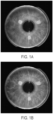
- FIGURES 1A and 1B show an embodiment of overlay imaging for registration of a patient eye depicting the iris.
- overlay images comprising a diagnostic image (lower or back image) over which a surgical image (upper or front image) has been superimposed and aligned at the limbus center of each respective image.
- substantially all of the iris structure as well as the pupil is shown in both the diagnostic image and the surgical image, where the pupil is slightly larger in the diagnostic image as compared to the surgical image.
- FIGURE 1A shows a first overlay image that is slightly out of rotational alignment
- FIGURE 1B shows a second overlay image that is more precisely aligned, as evident by the improved sharpness of the iris structures visible.
- the image shown in FIGURE 1B may represent an optimal alignment for cyclotorsion about the limbus center between the diagnostic image and the surgical image, and the alignment angle may be determined, or estimated, from the angular offset applied in FIGURE 1B , which is known.
- the images in FIGURE 1A and 1B represent examples of overlay imaging for registration of a patient eye, as disclosed herein. Accordingly, the overlay images shown in FIGURE 1A and FIGURE 1B may be displayed in a variety of different manners and techniques, as described herein. Because the overlay images shown in FIGURE 1A and FIGURE 1B are generated and displayed using an image processing system (see FIGURE 4 ), both the diagnostic image and the surgical image may be processed and displayed as digital images, allowing for various types of manipulation. For example, user input may be received to determine the actual angular offset displayed, allowing a user to manually determine the optimal alignment angle for cyclotorsion by 'tuning' the offset angle, as desired.
- user input may be received to determine a step angle of rotation for rapid bidirectional manual rotation.
- a dynamic, or animated, view of the images shown in FIGURES 1A and 1B may be generated by varying an offset angle of the surgical image relative to the diagnostic image.
- the offset angle may be varied over an angular range about the limbus center that includes the alignment angle, or the expected alignment angle.
- the display of the offset angle over the angular range may be repeated in a loop with bidirectional rotation. In this manner, a user may be able to confirm with a high degree of certainty, accuracy, and precision that the alignment angle selected is actually the optimal alignment angle.
- the animation loop about the angular range described above may be activated or repeated, for example, when the alignment angle has been tentatively determined in a first iteration, to enable determination of the alignment angle with increased, or optimal, accuracy in degrees of rotation, such as limited by the resolution of the raw image data or limited by the processing ability of the surgical laser system or the image processing system.
- color and contrast may be varied (not shown) for the diagnostic image or the surgical image or both.
- the diagnostic image may be a first color
- the surgical image may be a second color.
- the resulting image may accordingly appear as a third color that is a combination of the first color and the second color.
- a transparency of the overlaid surgical image may be varied (not shown) between low transparency (mostly or all opaque) to high transparency (mostly or all transparent).
- the transparency of the surgical image may be varied manually by the user, such as by user input specifying the transparency.
- the transparency of the surgical image may be automatically varied from low transparency to high transparency.
- the user may be enabled to determine the speed of the animation, as well as the transparency levels corresponding to low transparency and high transparency, respectively.
- the animation may transition from the diagnostic image to the surgical image without a change in the offset angle between the two images, to provide another view that enables highly precise and accurate determination of the alignment angle by more clearly presenting misaligned features in the display output to the user.
- the transparency animation may enable determination of the optimal alignment angle that appears best aligned in various different overlay displays.
- certain portions of the overlay image may be masked out or covered with a solid region, instead of the entire image within the limbus, for clarity and visual simplicity.
- markers are used in the overlay image, including iris markers that are indicative of particular iris structures, and geometric markers, such as a polygon or an ellipse, which may also be hollow markers for improved recognition of alignment.
- the number, type, location, size, among other features of the markers may be user selectable.
- the markers may include optical markers, such as regions of varied illumination, brightness, contrast, or other optical image property.
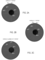
- FIGURES 2A, 2B, and 2C an embodiment of overlay imaging for registration of a patient eye depicting the iris using iris markers 204 is shown.
- Iris markers 204 are indicative of a particular feature in the iris of the eye (see FIGURES 1A and 1B ).
- overlay images for the limbus are shown indicative of a diagnostic image (lower or back image) respectively superimposed over a surgical image (upper or front image) and aligned at the limbus center of each respective image.
- FIGURES 2A, 2B, and 2C the image of the iris has been replaced with a uniform ring field for greater optical clarity in viewing iris markers 204.
- a first pupil 206-1 is shown for the diagnostic image and a second pupil 206-2 is shown for the surgical image, where first pupil 206-1 is slightly larger than second pupil 206-2. It is noted that in other embodiments, first pupil 206-1 and second pupil 206-2 may be the same size or different sizes, and the pupil size may be modulated by adjusting the illumination on the eye.
- a first reticle 202-1 is also shown for the diagnostic image and a second reticle 202-2 is shown for the surgical image. Reticles 202 cross at a common point that is the limbus center, which is not affected by a change in size of pupils 206.
- FIGURE 2A shows a third overlay image that has an angular offset of 7° about the limbus center and is accordingly out of rotational alignment
- FIGURE 2B shows a fourth overlay image that has an angular offset of -7° about the limbus center and is accordingly out of rotational alignment.
- the diagnostic image having reticle 202-1 is shown at alignment with vertical and horizontal.
- FIGURE 2C shows a fifth overlay image that is more precisely aligned, albeit at an offset of 3° from vertical or horizontal.
- iris marker 204-2 is offset from iris marker 204-1, and may be more clearly visible that an actual picture of the iris that iris markers 204 represent. Iris markers 204 may be generated using the same image processing operation from a respective iris image.
- iris marker 204-2 is offset in an opposite direction from iris marker 204-1 as compared to FIGURE 2A .
- iris markers 204 appear as singular markers due to the precise alignment in the overlay image, and reticle 202 also appears as a single reticle.
- FIGURES 1A and 1B it is noted that various different modifications and techniques may be used with the overlay images shown in FIGURES 2A, 2B, and 2C .
- certain portions of the iris may be blended in with a varying degree of transparency, as described above.
- Iris markers 204 may be shown along with the actual iris structure represented by iris markers 204, or any desired portion thereof.
- Color and transparency of any of the image elements shown or described may be varied manually or automatically in an animation loop, as described above, with user configuration of various display parameters relating to color, time, transparency, among others.
- the alignment angle may be determined relative to any offset angle of the diagnostic image, as shown in FIGURE 2C .
- Iris markers 204 may be indicative of a particular feature in the iris of the eye (see FIGURES 1A and 1B ) and are the same as described above with respect to FIGURES 2A, 2B, and 2C .
- overlay images for the limbus are shown indicative of a diagnostic image (lower or back image) respectively superimposed over a surgical image (upper or front image) and aligned at the limbus center of each respective image.
- FIGURES 3A, 3B, and 3C the image of the iris has been replaced with a uniform ring field for greater optical clarity in viewing iris markers 204 and geometric markers 302.
- a first pupil 206-1 pupil is shown for the diagnostic image and a second pupil 206-2 is shown for the surgical image, where first pupil 206-1 is slightly larger than second pupil 206-2.
- a first reticle 202-1 is also shown for the diagnostic image and a second reticle 202-2 is shown for the surgical image.
- Reticles 202 cross at a common point that is the limbus center, which is not affected by a change in size of pupils 206.
- FIGURE 3A shows a sixth overlay image that has an angular offset of 2° about the limbus center and is accordingly out of rotational alignment
- FIGURE 3B shows a seventh overlay image that has an angular offset of -2° about the limbus center and is accordingly out of rotational alignment.
- the diagnostic image having reticle 202-1 is shown at alignment with vertical and horizontal.
- FIGURE 3C shows an eighth overlay image that is more precisely aligned, albeit at an offset of -3° from vertical or horizontal.
- geometric markers 302 are shown as circles, which is a special case of an ellipse more generally. Geometric markers 302 are further shown as hollow markers, which may enable a more precise or accurate alignment over the entire marker, as well as over the visible portion from the hollow space of the underlying image (here iris markers 204).
- geometric marker 302-1 is in the diagnostic image, while geometric marker 302-2 is in the surgical image.
- various different modifications and techniques may be used with the overlay images shown in FIGURES 3A, 3B, and 3C .
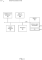
- image processing system 400 includes processor 401 coupled via shared bus 402 to memory media collectively identified as memory 410.
- Image processing system 400 further includes communication interface 420 that can interface image processing system 400 to various external entities, such as a network or instrumentation bus included with a surgical laser system.
- image processing system 400 includes display interface 404 that connects shared bus 402, or another bus, with an output port for one or more displays, such as a display of a surgical laser system, an ocular display of a surgical microscope, or another display.
- image processing system 400 may further include a camera interface 406 for acquisition of surgical images from a camera included in the surgical laser system.
- camera interface 406 includes a camera and suitable optics for overlay imaging for registration of a patient eye for laser surgery.
- memory 410 encompasses persistent and volatile media, fixed and removable media, and magnetic and semiconductor media. Memory 410 is operable to store instructions, data, or both. Memory 410 as shown includes sets or sequences of instructions, namely, an operating system 412, and an overlay image processing application 414.
- Operating system (OS) 412 may be a UNIX or UNIX-like operating system, a Windows ® family operating system, or another suitable operating system.
- image processing system 400 may be integrated with different types of equipment.
- image processing system 400 is integrated with a surgical microscope.
- the surgical microscope may be integrated within the surgical laser system.
- image processing system 400 may be implemented using more components in some embodiments.
- Method 500 may be performed by overlay image processing application 414 in FIGURE 4 .
- Method 500 begins at step 502, by acquiring a surgical image including the limbus of a patient eye subject to ophthalmic surgery.
- the ophthalmic surgery may be laser surgery.
- the surgical image is overlaid on a diagnostic image including the limbus, the diagnostic image being previously acquired from the patient eye.
- the surgical image is displayed being rotated about the first limbus center over an angular range, the surgical image having a transparency enabling simultaneous viewing of the surgical image and the diagnostic image during at least a portion of the angular range, and the angular range including an alignment angle for the surgical image at which the surgical image and the diagnostic image are cyclotorsonally aligned with respect to the first limbus center and the second limbus center, respectively.
- step 508 user input specifying the alignment angle is received. It is noted that step 508 may be repeated or performed iteratively in conjunction with other steps in method 500.
- step 510 the surgical image is displayed rotated about the first limbus center at the alignment angle.
- step 512 the transparency of the surgical image is varied from low transparency to high transparency.
- methods and systems for overlay imaging for registration of a patient eye for laser surgery include aligning and overlaying a surgical image of the limbus over a previously acquired diagnostic image of the limbus.
- the surgical image is displayed with a degree of transparency and enabled to rotate about the limbus center.
- Various types of colors, markers, contrast, and backgrounds may be used to generate a display for determining the alignment angle between the diagnostic image and the surgical image.
Landscapes
- Health & Medical Sciences (AREA)
- Life Sciences & Earth Sciences (AREA)
- Engineering & Computer Science (AREA)
- Surgery (AREA)
- Veterinary Medicine (AREA)
- General Health & Medical Sciences (AREA)
- Biomedical Technology (AREA)
- Heart & Thoracic Surgery (AREA)
- Public Health (AREA)
- Animal Behavior & Ethology (AREA)
- Physics & Mathematics (AREA)
- Ophthalmology & Optometry (AREA)
- Molecular Biology (AREA)
- Medical Informatics (AREA)
- Nuclear Medicine, Radiotherapy & Molecular Imaging (AREA)
- Robotics (AREA)
- General Physics & Mathematics (AREA)
- Theoretical Computer Science (AREA)
- Biophysics (AREA)
- Optics & Photonics (AREA)
- Vascular Medicine (AREA)
- Human Computer Interaction (AREA)
- Pathology (AREA)
- Oral & Maxillofacial Surgery (AREA)
- Computer Vision & Pattern Recognition (AREA)
- Eye Examination Apparatus (AREA)
- Laser Surgery Devices (AREA)
- Radiation-Therapy Devices (AREA)
Description
- The present disclosure relates to ophthalmic surgery, and more specifically, to overlay imaging for registration of a patient eye for laser surgery.
- In ophthalmology, eye surgery, or ophthalmic surgery, saves and improves the vision of tens of thousands of patients every year. However, given the sensitivity of vision to even small changes in the eye and the minute and delicate nature of many eye structures, ophthalmic surgery is difficult to perform and the reduction of even minor or uncommon surgical errors or modest improvements in accuracy of surgical techniques can make an enormous difference in the patient's vision after the surgery.
- Ophthalmic surgery is performed on the eye and accessory visual structures. More specifically, various types of laser ablation surgery (or simply 'laser surgery') may be performed on the cornea, lens, or other structures in the eye for clinical treatment purposes. Typically, prior to laser surgery a diagnostic image of the eye is acquired to characterize the eye and to identify specific treatment locations, among other uses. Subsequently, when the laser surgery is initiated on the eye using a surgical laser system, an initial step in the surgery is registration of the eye to confirm the identity of the patient and to correlate the eye to the diagnostic image. Typical surgical laser systems display the diagnostic image next to a surgical image of the eye being acquired for registration purposes. During registration, the surgeon or other medical personnel may find that precise rotational alignment of the eye using the two images displayed next to one another, the diagnostic image and the surgical image, is difficult or time-consuming.
- Document
EP 1 800 636 A1 describes a method for aligning a first eye image collected using a wavefront aberrometer and a second eye image collected at a surgery site using an imaging device, wherein the method includes the steps of determining a limbus location on the first eye image and the second eye image and aligning the limbus locations vertically and horizontally with reference to a calculated center of the limbus. Once the limbus locations are aligned, the first and second eye images are rotated relative to each other at predetermined intervals, wherein, at each point, a correlation is performed using a blood vessel location separation as an alignment criterion, and, from the correlation, an optimal first and second image alignment is identified. - In document
US 2007/055222 A1 , a method is described in which an iris or eye image is taken during a refractive diagnostic analysis, wherein the image is employed for aligning data from the analysis with data from other refractive analysis instruments, as well as aligning a refractive surgical laser with the eye for treatment. In particular, for refractive treatment using LASIK with an Excimer laser, a camera takes an image of the iris, and a treatment developed from diagnostic information is normalized to that iris image, wherein normalization can include translation, rotation, scaling, or other transformational techniques.WO 2016/061454 discloses to align overlapped measurement images and surgical images of the eye on the bases of ocular features and by translation and rotation of the images. The correlation between the features can be done by image processing or manually by the operator. - The present invention relates to a computer-implemented method for registration of patient eyes for ophthalmic surgery according to claim 1 and an image processing system according to claim 8. The method includes acquiring a surgical image including the limbus of a patient eye subject to ophthalmic surgery, and overlaying the surgical image on a diagnostic image including the limbus, the diagnostic image being previously acquired from the patient eye. The method includes aligning a first limbus center of the surgical image with a second limbus center of the diagnostic image, and displaying the surgical image being rotated about the first limbus center over an angular range. In the method, the surgical image has a transparency enabling simultaneous viewing of the surgical image and the diagnostic image during at least a portion of the angular range. In the method, the angular range includes an alignment angle for the surgical image at which the surgical image and the diagnostic image are cyclotorsonally aligned with respect to the first limbus center and the second limbus center, respectively.
- In any of the disclosed embodiments of the method, the surgical image and the diagnostic image include at least a portion of the iris of the patient's eye.
- In any of the disclosed embodiments of the method, both the surgical image and the diagnostic image may respectively include at least one identical marker at a common location with respect to the iris of the patient's eye. In the method, the marker is an indication of an iris structure of the iris displayed over a uniform background in place of the iris. In the method, a first marker of the surgical image has a first color, and a second marker of the diagnostic image has a second color. In the method, the marker may have a hollow shape. In the method, the hollow shape may include at least one of a polygon and an ellipse.
- In any of the disclosed embodiments of the method, displaying the surgical image may further include displaying the surgical image being incrementally rotated about the first limbus center over a step angle of rotation, in response to user input indicating the step angle.
- In any of the disclosed embodiments, the method may further include receiving user input specifying the alignment angle, displaying the surgical image rotated about the first limbus center at the alignment angle, and varying the transparency of the surgical image from low transparency to high transparency.
- In any of the disclosed embodiments, the method may further include receiving user input to select at least one of the displayed transparency, the range of transparency from high transparency to low transparency, a step transparency within the transparency range, a first color in the surgical image, a second color in the diagnostic image, a number of markers, a type of marker, a location of a marker, a contrast of the iris, a displayed portion of the iris, the angular range, and a step angle within the angular range.
- Another disclosed aspect includes an image processing system for overlay imaging for registration of a patient eye for ophthalmic surgery, the image processing system including a processor enable to access memory media storing instructions executable by the processor to perform the method, or any portions thereof. A further disclosed aspect includes an article of manufacture comprising non-transitory memory media for characterizing membranes at vitreoretinal interfaces, the memory media storing instructions executable by a processor to perform the method, or any portions thereof..
- For a more complete understanding of the present invention and its features and advantages, reference is now made to the following description, taken in conjunction with the accompanying drawings, in which:
-
FIGURES 1A and 1B show an embodiment of overlay imaging for registration of a patient eye depicting the iris; -
FIGURES 2A, 2B, and 2C shows an embodiment of overlay imaging for registration of a patient eye using iris markers; -
FIGURES 3A, 3B, and 3C shows an embodiment of overlay imaging for registration of a patient eye using iris markers and shape markers; -
FIGURE 4 is a block diagram of selected elements of an embodiment of an image processing system for overlay imaging for registration of a patient eye; and -
FIGURE 5 is a flow chart of selected elements of a method for overlay imaging for registration of a patient eye. - In the following description, details are set forth by way of example to facilitate discussion of the disclosed subject matter. It should be apparent to a person of ordinary skill in the field, however, that the disclosed embodiments are exemplary and not exhaustive of all possible embodiments.
- As used herein, a hyphenated form of a reference numeral refers to a specific instance of an element and the un-hyphenated form of the reference numeral refers to the collective element. Thus, for example, device '12-1' refers to an instance of a device class, which may be referred to collectively as devices '12' and any one of which may be referred to generically as a device `12'.
- As noted above, registration of a patient's eye is performed as an initial step during various types of ophthalmic surgery. In particular, for laser surgery of the cornea or eye lens, an image of the limbus of the eye may be acquired during diagnosis, referred to as a `diagnostic image'. The diagnostic image may be used, along with other acquired data and measurements, to determine a treatment plan for the eye, such as a surgical plan for the laser surgery. When the patient is prepared for the laser surgery and is positioned within the laser surgery system, a 'surgical image' of the patient's eye, including the limbus, is acquired and used for registration of the eye. The registration using the surgical image serves to identify the patient and to confirm that the correct eye is undergoing laser surgery.
- Additionally, because cyclotorsion of the eye may occur to some degree, registration may further involve a precise rotational alignment of the eye with respect to the diagnostic image. Because the ability to rotate the patient may be limited, an alignment angle may be determined by the surgical laser system representing a slight rotational (angular) offset between the diagnostic image and the surgical image. The alignment angle may then be recorded by the surgical laser system and used to rotationally offset laser activity on the eye accordingly. The alignment angle is generally measured about a rotation point that is the geometric center of the limbus, which provides a more stable rotational alignment point than the center of the pupil, which can change as the pupil size changes. To the extent that the pupil diameter is somewhat comparable in each of the images, the limbus also provides a stable circular structure that can be used for precise scaling alignment of the diagnostic image to the surgical image, even when the two images differ in size, resolution, color, and wavelength of light used, among other aspects.
- Because the precise rotational alignment of the eye is crucial for properly performing the surgical plan for the laser surgery, the surgeon or other surgical personnel will typically verify that the alignment angle determined has a high degree of accuracy. Thus, the checking and confirmation of the alignment angle may represent an important operation during registration of the eye for the laser surgery.
- Conventional surgical laser systems are typically equipped to provide the diagnostic image next to the surgical image on a display screen that is viewed by an operator of the surgical laser system, often the surgeon or other surgical personnel. The surgical image may be acquired using microscope optics and a camera that is included with the surgical laser system. However, determining the alignment angle between the diagnostic image and the surgical image when the two images are displayed next to one another may be difficult and time consuming, because such an arrangement may be challenging for human visual cognition to interpret. Thus, by virtue of the side-by-side arrangement found in conventional surgical laser systems, the overall accuracy of the alignment angle determined in this manner may be limited, which is undesirable because it represents a potential source of error for performing the surgical plan.
- As will be described in further detail herein, the inventors of the present disclosure have provided methods and systems of overlay imaging for registration of a patient eye for laser surgery. Instead of presenting the diagnostic image next to the surgical image during registration, the methods and systems of overlay imaging for registration of a patient eye disclosed herein display the two images as a single overlay image comprised of the surgical image superimposed on the diagnostic image. The methods and systems of overlay imaging for registration of a patient eye disclosed herein provide a variable degree of transparency, from low transparency to high transparency, of the surgical image. The methods and systems of overlay imaging for registration of a patient eye disclosed herein align the diagnostic image and the surgical image based on the limbus in each respective image, and enable rotation of the surgical image relative to the diagnostic image about the limbus center. The methods and systems of overlay imaging for registration of a patient eye disclosed herein enable displaying the surgical image being rotated relative to the underlying diagnostic image about the limbus center. The surgical image is rotated about an angular range that includes the alignment angle, such as with a video loop created with individual frames at individual step angles of the rotation, to allow human visual cognition to more accurately and precisely determine or verify the alignment angle. The methods and systems of overlay imaging for registration of a patient eye disclosed herein provide markers that are indicative of iris structures that are unique to the eye. Other geometric markers, such as polygons or ellipses, may also be used. The methods and systems of overlay imaging for registration of a patient eye disclosed herein may enable selection and configuration by users of various features for flexible and customizable displays for determining and verifying the alignment angle. The methods and systems of overlay imaging for registration of a patient eye disclosed herein may be implemented using an image processing system that is included with or that operates with the surgical laser system.
- Referring now to the drawings,
FIGURES 1A and 1B show an embodiment of overlay imaging for registration of a patient eye depicting the iris. InFIGURES 1A and 1B overlay images comprising a diagnostic image (lower or back image) over which a surgical image (upper or front image) has been superimposed and aligned at the limbus center of each respective image. InFIGURES 1A and 1B , substantially all of the iris structure as well as the pupil is shown in both the diagnostic image and the surgical image, where the pupil is slightly larger in the diagnostic image as compared to the surgical image. As shown,FIGURE 1A shows a first overlay image that is slightly out of rotational alignment, whileFIGURE 1B shows a second overlay image that is more precisely aligned, as evident by the improved sharpness of the iris structures visible. InFIGURE 1B , the more sharp alignment is visible in the clarity of the iris structures, particularly as compared withFIGURE 1A . Accordingly, the image shown inFIGURE 1B may represent an optimal alignment for cyclotorsion about the limbus center between the diagnostic image and the surgical image, and the alignment angle may be determined, or estimated, from the angular offset applied inFIGURE 1B , which is known. - As shown, the images in
FIGURE 1A and 1B represent examples of overlay imaging for registration of a patient eye, as disclosed herein. Accordingly, the overlay images shown inFIGURE 1A and FIGURE 1B may be displayed in a variety of different manners and techniques, as described herein. Because the overlay images shown inFIGURE 1A and FIGURE 1B are generated and displayed using an image processing system (seeFIGURE 4 ), both the diagnostic image and the surgical image may be processed and displayed as digital images, allowing for various types of manipulation. For example, user input may be received to determine the actual angular offset displayed, allowing a user to manually determine the optimal alignment angle for cyclotorsion by 'tuning' the offset angle, as desired. In some embodiments, user input may be received to determine a step angle of rotation for rapid bidirectional manual rotation. Although only static images can be displayed in the drawings, it will be appreciated that a dynamic, or animated, view of the images shown inFIGURES 1A and 1B may be generated by varying an offset angle of the surgical image relative to the diagnostic image. In various embodiments, the offset angle may be varied over an angular range about the limbus center that includes the alignment angle, or the expected alignment angle. The display of the offset angle over the angular range may be repeated in a loop with bidirectional rotation. In this manner, a user may be able to confirm with a high degree of certainty, accuracy, and precision that the alignment angle selected is actually the optimal alignment angle. The animation loop about the angular range described above may be activated or repeated, for example, when the alignment angle has been tentatively determined in a first iteration, to enable determination of the alignment angle with increased, or optimal, accuracy in degrees of rotation, such as limited by the resolution of the raw image data or limited by the processing ability of the surgical laser system or the image processing system. - It is further noted that color and contrast may be varied (not shown) for the diagnostic image or the surgical image or both. For example, the diagnostic image may be a first color, while the surgical image may be a second color. When both images are aligned, the resulting image may accordingly appear as a third color that is a combination of the first color and the second color.
- Other types of displays may also be generated, as described herein. For example, a transparency of the overlaid surgical image may be varied (not shown) between low transparency (mostly or all opaque) to high transparency (mostly or all transparent). The transparency of the surgical image may be varied manually by the user, such as by user input specifying the transparency. As an animation, the transparency of the surgical image may be automatically varied from low transparency to high transparency. The user may be enabled to determine the speed of the animation, as well as the transparency levels corresponding to low transparency and high transparency, respectively. In this manner, the animation may transition from the diagnostic image to the surgical image without a change in the offset angle between the two images, to provide another view that enables highly precise and accurate determination of the alignment angle by more clearly presenting misaligned features in the display output to the user. As with the other techniques for overlay imaging disclosed herein, the transparency animation may enable determination of the optimal alignment angle that appears best aligned in various different overlay displays.
- Still further, as will be shown in the subsequent figures, certain portions of the overlay image may be masked out or covered with a solid region, instead of the entire image within the limbus, for clarity and visual simplicity. Various types of markers are used in the overlay image, including iris markers that are indicative of particular iris structures, and geometric markers, such as a polygon or an ellipse, which may also be hollow markers for improved recognition of alignment. The number, type, location, size, among other features of the markers may be user selectable. The markers may include optical markers, such as regions of varied illumination, brightness, contrast, or other optical image property.
- Referring now to
FIGURES 2A, 2B, and 2C , an embodiment of overlay imaging for registration of a patient eye depicting the iris usingiris markers 204 is shown.Iris markers 204 are indicative of a particular feature in the iris of the eye (seeFIGURES 1A and 1B ). InFIGURES 2A, 2B, and 2C overlay images for the limbus are shown indicative of a diagnostic image (lower or back image) respectively superimposed over a surgical image (upper or front image) and aligned at the limbus center of each respective image. InFIGURES 2A, 2B, and 2C , the image of the iris has been replaced with a uniform ring field for greater optical clarity in viewingiris markers 204. InFIGURES 2A, 2B, and 2C , a first pupil 206-1 is shown for the diagnostic image and a second pupil 206-2 is shown for the surgical image, where first pupil 206-1 is slightly larger than second pupil 206-2. It is noted that in other embodiments, first pupil 206-1 and second pupil 206-2 may be the same size or different sizes, and the pupil size may be modulated by adjusting the illumination on the eye. InFIGURES 2A, 2B, and 2C , a first reticle 202-1 is also shown for the diagnostic image and a second reticle 202-2 is shown for the surgical image.Reticles 202 cross at a common point that is the limbus center, which is not affected by a change in size of pupils 206. As shown,FIGURE 2A shows a third overlay image that has an angular offset of 7° about the limbus center and is accordingly out of rotational alignment,FIGURE 2B shows a fourth overlay image that has an angular offset of -7° about the limbus center and is accordingly out of rotational alignment. The diagnostic image having reticle 202-1 is shown at alignment with vertical and horizontal.FIGURE 2C shows a fifth overlay image that is more precisely aligned, albeit at an offset of 3° from vertical or horizontal. - In
FIGURE 2A , iris marker 204-2 is offset from iris marker 204-1, and may be more clearly visible that an actual picture of the iris thatiris markers 204 represent.Iris markers 204 may be generated using the same image processing operation from a respective iris image. InFIGURE 2B , iris marker 204-2 is offset in an opposite direction from iris marker 204-1 as compared toFIGURE 2A . InFIGURE 2C ,iris markers 204 appear as singular markers due to the precise alignment in the overlay image, andreticle 202 also appears as a single reticle. - As with
FIGURES 1A and 1B , it is noted that various different modifications and techniques may be used with the overlay images shown inFIGURES 2A, 2B, and 2C . In some embodiments, certain portions of the iris may be blended in with a varying degree of transparency, as described above.Iris markers 204 may be shown along with the actual iris structure represented byiris markers 204, or any desired portion thereof. Color and transparency of any of the image elements shown or described may be varied manually or automatically in an animation loop, as described above, with user configuration of various display parameters relating to color, time, transparency, among others. In particular, when an offset angle of the diagnostic image is not aligned with vertical or horizontal, the alignment angle may be determined relative to any offset angle of the diagnostic image, as shown inFIGURE 2C . - Referring now to
FIGURES 3A, 3B, and 3C , an embodiment of overlay imaging for registration of a patient eye depicting the iris usingiris markers 204 andgeometric markers 302.Iris markers 204 may be indicative of a particular feature in the iris of the eye (seeFIGURES 1A and 1B ) and are the same as described above with respect toFIGURES 2A, 2B, and 2C . InFIGURES 3A, 3B, and 3C , overlay images for the limbus are shown indicative of a diagnostic image (lower or back image) respectively superimposed over a surgical image (upper or front image) and aligned at the limbus center of each respective image. InFIGURES 3A, 3B, and 3C , the image of the iris has been replaced with a uniform ring field for greater optical clarity in viewingiris markers 204 andgeometric markers 302. InFIGURES 3A, 3B, and 3C , a first pupil 206-1 pupil is shown for the diagnostic image and a second pupil 206-2 is shown for the surgical image, where first pupil 206-1 is slightly larger than second pupil 206-2. InFIGURES 3A, 3B, and 3C , a first reticle 202-1 is also shown for the diagnostic image and a second reticle 202-2 is shown for the surgical image.Reticles 202 cross at a common point that is the limbus center, which is not affected by a change in size of pupils 206. As shown,FIGURE 3A shows a sixth overlay image that has an angular offset of 2° about the limbus center and is accordingly out of rotational alignment,FIGURE 3B shows a seventh overlay image that has an angular offset of -2° about the limbus center and is accordingly out of rotational alignment. The diagnostic image having reticle 202-1 is shown at alignment with vertical and horizontal.FIGURE 3C shows an eighth overlay image that is more precisely aligned, albeit at an offset of -3° from vertical or horizontal. - In
FIGURES 3A, 3B, and 3C ,geometric markers 302 are shown as circles, which is a special case of an ellipse more generally.Geometric markers 302 are further shown as hollow markers, which may enable a more precise or accurate alignment over the entire marker, as well as over the visible portion from the hollow space of the underlying image (here iris markers 204). InFIGURES 3A, 3B, and 3C , geometric marker 302-1 is in the diagnostic image, while geometric marker 302-2 is in the surgical image. As with the previous figures described in detail above, it is noted that various different modifications and techniques may be used with the overlay images shown inFIGURES 3A, 3B, and 3C . - Referring now to
FIGURE 4 , a block diagram illustrating selected elements of an embodiment of animage processing system 400 is presented. In the embodiment depicted inFIGURE 4 ,image processing system 400 includesprocessor 401 coupled via sharedbus 402 to memory media collectively identified asmemory 410. -
Image processing system 400, as depicted inFIGURE 4 , further includescommunication interface 420 that can interfaceimage processing system 400 to various external entities, such as a network or instrumentation bus included with a surgical laser system. In embodiments suitable for overlay imaging for registration of a patient eye for laser surgery,image processing system 400, as depicted inFIGURE 4 , includesdisplay interface 404 that connects sharedbus 402, or another bus, with an output port for one or more displays, such as a display of a surgical laser system, an ocular display of a surgical microscope, or another display. As shown,image processing system 400 may further include acamera interface 406 for acquisition of surgical images from a camera included in the surgical laser system. In some embodiments,camera interface 406 includes a camera and suitable optics for overlay imaging for registration of a patient eye for laser surgery. - In
FIGURE 4 ,memory 410 encompasses persistent and volatile media, fixed and removable media, and magnetic and semiconductor media.Memory 410 is operable to store instructions, data, or both.Memory 410 as shown includes sets or sequences of instructions, namely, anoperating system 412, and an overlayimage processing application 414. Operating system (OS) 412 may be a UNIX or UNIX-like operating system, a Windows® family operating system, or another suitable operating system. - In various embodiments,
image processing system 400 may be integrated with different types of equipment. In one embodiment,image processing system 400 is integrated with a surgical microscope. The surgical microscope may be integrated within the surgical laser system. - Modifications, additions, or omissions may be made to
image processing system 400 without departing from the scope of the disclosure. The components and elements ofimage processing system 400, as described herein, may be integrated or separated according to particular applications.Image processing system 400 may be implemented using more components in some embodiments. - Referring now to
FIGURE 5 , a flow chart of selected elements of an embodiment of amethod 500 for overlay imaging for registration of a patient eye for laser surgery, as described herein, is depicted in flowchart form.Method 500 may be performed by overlayimage processing application 414 inFIGURE 4 . -
Method 500 begins atstep 502, by acquiring a surgical image including the limbus of a patient eye subject to ophthalmic surgery. The ophthalmic surgery may be laser surgery. Atstep 504, the surgical image is overlaid on a diagnostic image including the limbus, the diagnostic image being previously acquired from the patient eye. Atstep 506, the surgical image is displayed being rotated about the first limbus center over an angular range, the surgical image having a transparency enabling simultaneous viewing of the surgical image and the diagnostic image during at least a portion of the angular range, and the angular range including an alignment angle for the surgical image at which the surgical image and the diagnostic image are cyclotorsonally aligned with respect to the first limbus center and the second limbus center, respectively. Atstep 508, user input specifying the alignment angle is received. It is noted thatstep 508 may be repeated or performed iteratively in conjunction with other steps inmethod 500. Atstep 510, the surgical image is displayed rotated about the first limbus center at the alignment angle. Atstep 512, the transparency of the surgical image is varied from low transparency to high transparency. - As disclosed herein, methods and systems for overlay imaging for registration of a patient eye for laser surgery include aligning and overlaying a surgical image of the limbus over a previously acquired diagnostic image of the limbus. The surgical image is displayed with a degree of transparency and enabled to rotate about the limbus center. Various types of colors, markers, contrast, and backgrounds may be used to generate a display for determining the alignment angle between the diagnostic image and the surgical image.
Claims (14)
- A computer-implemented method for registration of patient eyes for ophthalmic surgery, the method comprising:acquiring (502) a surgical image including the limbus of a patient eye subject to ophthalmic surgery;overlaying (504) the surgical image on a diagnostic image including the limbus, the diagnostic image being previously acquired from the patient eye;aligning a first limbus center of the surgical image with a second limbus center of the diagnostic image;generating, using an image processing operation, at least one first marker (204-2) in the surgical image and at least one second marker (204-1) in the diagnostic image at a common location of the iris of the patient eye, wherein the markers are iris markers (204, 204-1, 204-2) indicative of an iris structure; anddisplaying (506) the surgical image being rotated about the first limbus center over an angular range, wherein the surgical image has a transparency enabling simultaneous viewing of the surgical image and the diagnostic image during at least a portion of the angular range, and wherein the angular range includes an alignment angle for the surgical image at which the surgical image and the diagnostic image are cyclotorsonally aligned with respect to the first limbus center and the second limbus center, respectively,wherein the displaying includes displaying the at least one first marker in the surgical image and the at least second marker in the diagnostic image.
- The method of claim 1, wherein the surgical image and the diagnostic image include at least a portion of the iris of the patient's eye.
- The method of claim 1,wherein the marker is displayed over a uniform background in place of the iris, orwherein the marker is a hollow shape preferably including at least one of: a polygon and an ellipse.
- The method of claim 1, wherein a first marker of the surgical image has a first color, and a second marker of the diagnostic image has a second color.
- The method of claim 1, wherein displaying (506) the surgical image further comprises:
displaying the surgical image being incrementally rotated about the first limbus center over a step angle of rotation, in response to user input indicating the step angle. - The method of claim 1, further comprising:receiving (508) user input specifying the alignment angle;displaying (510) the surgical image rotated about the first limbus center at the alignment angle; andvarying (512) the transparency of the surgical image from low transparency to high transparency.
- The method of claim 1, further comprising receiving user input to select at least one of:the transparency displayed;a range of transparency from high transparency to low transparency;a step transparency within the transparency range;a first color in the surgical image;a second color in the diagnostic image;a number of markers;a type of marker;a location of a marker;a contrast of the iris;a displayed portion of the iris;the angular range; anda step angle within the angular range.
- An image processing system (400) for registration of patient eyes for ophthalmic surgery, the image processing system (400) comprising:a processor (401) enabled to access memory media (410) storing instructions executable by the processor (401) to,acquire (502) a surgical image including the limbus of a patient eye subject to ophthalmic surgery;overlay (504) the surgical image on a diagnostic image including the limbus, the diagnostic image being previously acquired from the patient eye;align a first limbus center of the surgical image with a second limbus center of the diagnostic image;generate, using an image processing operation, at least one first marker (204-2) in the surgical image and at least a second marker (204-1) in the diagnostic image at a common location of the iris of the patient eye, wherein the markers are iris markers (204, 204-1, 204-2) indicative of an iris structure; anddisplay (506) the surgical image being rotated about the first limbus center over an angular range, wherein the surgical image has a transparency enabling simultaneous viewing of the surgical image and the diagnostic image during at least a portion of the angular range, and wherein the angular range includes an alignment angle for the surgical image at which the surgical image and the diagnostic image are cyclotorsonally aligned with respect to the first limbus center and the second limbus center, respectively,wherein the displaying includes displaying the at least one first marker in the surgical image and the at least one second marker in the diagnostic image.
- The image processing system (400) of claim 8, wherein the surgical image and the diagnostic image include at least a portion of the iris of the patient's eye.
- The image processing system (400) of claim 8, whereinthe marker is displayed over a uniform background in place of the iris, orwherein the marker is a hollow shape preferably including at least one of: a polygon and an ellipse.
- The image processing system (400) of claim 8, wherein a first marker of the surgical image has a first color, and a second marker of the diagnostic image has a second color.
- The image processing system (400) of claim 8, wherein the instructions to display the surgical image further comprise instructions to:
display the surgical image being incrementally rotated about the first limbus center over a step angle of rotation, in response to user input indicating the step angle. - The image processing system (400) of claim 8, further comprising instructions to:receive (508) user input specifying the alignment angle;display (510) the surgical image rotated about the first limbus center at the alignment angle; andvary (512) the transparency of the surgical image from low transparency to high transparency.
- The image processing system (400) of claim 8, further comprising instructions to receive user input to select at least one of:the transparency displayed;a range of transparency from high transparency to low transparency;a step transparency within the transparency range;a first color in the surgical image;a second color in the diagnostic image;a number of markers;a type of marker;a location of a marker;a contrast of the iris;a displayed portion of the iris;the angular range; anda step angle within the angular range.
Applications Claiming Priority (1)
| Application Number | Priority Date | Filing Date | Title |
|---|---|---|---|
| PCT/IB2016/052496 WO2017191487A1 (en) | 2016-05-02 | 2016-05-02 | Overlay imaging for registration of a patient eye for laser surgery |
Publications (2)
| Publication Number | Publication Date |
|---|---|
| EP3451898A1 EP3451898A1 (en) | 2019-03-13 |
| EP3451898B1 true EP3451898B1 (en) | 2023-06-21 |
Family
ID=56015054
Family Applications (1)
| Application Number | Title | Priority Date | Filing Date |
|---|---|---|---|
| EP16723532.4A Active EP3451898B1 (en) | 2016-05-02 | 2016-05-02 | Overlay imaging for registration of a patient eye for laser surgery |
Country Status (8)
| Country | Link |
|---|---|
| US (1) | US10898268B2 (en) |
| EP (1) | EP3451898B1 (en) |
| JP (1) | JP6797936B2 (en) |
| CN (1) | CN109068975B (en) |
| AU (1) | AU2016405856B2 (en) |
| CA (1) | CA3016282C (en) |
| ES (1) | ES2952550T3 (en) |
| WO (1) | WO2017191487A1 (en) |
Families Citing this family (12)
| Publication number | Priority date | Publication date | Assignee | Title |
|---|---|---|---|---|
| ES2967664T3 (en) * | 2018-06-20 | 2024-05-03 | Alcon Inc | Auxiliary surgical field visualization system |
| EP3817682B1 (en) * | 2018-07-02 | 2024-05-15 | Alcon Inc. | Shaking image for registration verification |
| WO2020130121A1 (en) * | 2018-12-21 | 2020-06-25 | 株式会社クレスコ | Ophthalmologic diagnostic device |
| EP3945994B1 (en) | 2019-03-27 | 2024-10-23 | Alcon Inc. | System and method of utilizing one or more images of an eye in medical procedures |
| CN112019796A (en) * | 2019-05-30 | 2020-12-01 | 海南核电有限公司 | Electronic reticle for identifying position of top cover guide post and dividing method |
| CA3154216A1 (en) | 2019-10-11 | 2021-04-15 | Beyeonics Surgical Ltd. | System and method for improved electronic assisted medical procedures |
| JP7573027B2 (en) * | 2019-10-29 | 2024-10-24 | アルコン インコーポレイティド | SYSTEM AND METHOD FOR UTILIZING THREE-DIMENSIONAL OVERLAY IN MEDICAL PROCEDURE - Patent application |
| EP3862804A1 (en) * | 2020-02-05 | 2021-08-11 | Leica Instruments (Singapore) Pte. Ltd. | Apparatuses, methods and computer programs for a microscope system |
| CN111407506A (en) * | 2020-03-27 | 2020-07-14 | 东莞爱尔眼科医院有限公司 | Image processing method and device for assisting eye surgery in positioning cornea center |
| EP4197428B1 (en) * | 2021-12-20 | 2026-05-20 | Ziemer Ophthalmic Systems Ag | OPTHALMOLOGICAL TREATMENT DEVICE FOR DETERMINING THE ANGLE OF AN EYE |
| CN117338513B (en) * | 2023-07-28 | 2026-02-27 | 武汉安顿医疗技术有限责任公司 | A central positioning system and method for femtosecond laser corneal refractive surgery |
| DE102023212259A1 (en) * | 2023-12-06 | 2025-06-12 | Carl Zeiss Meditec Ag | Computer-implemented method, computer program product, and laser therapy device for verifying the registration of patient eyes |
Citations (17)
| Publication number | Priority date | Publication date | Assignee | Title |
|---|---|---|---|---|
| WO2001028476A1 (en) | 1999-10-21 | 2001-04-26 | Technolas Gmbh Ophthalmologische Systeme | Iris recognition and tracking for optical treatment |
| WO2001078584A2 (en) | 2000-04-19 | 2001-10-25 | Alcon Universal Ltd. | Eye registration and astigmatism alignment control systems and method |
| WO2002087442A1 (en) | 2001-04-27 | 2002-11-07 | Bausch & Lomb Incorporated | Iris pattern recognition and alignment |
| WO2003053228A2 (en) | 2001-12-21 | 2003-07-03 | Sensomotoric Instruments Gmbh | Method and apparatus for eye registration |
| US20030223037A1 (en) | 2002-05-30 | 2003-12-04 | Visx, Incorporated | Methods and systems for tracking a torsional orientation and position of an eye |
| WO2004089214A2 (en) | 2003-04-11 | 2004-10-21 | Bausch & Lomb Inc. | System and method for acquiring data and aligning and tracking of an eye |
| US20070142826A1 (en) | 2005-12-16 | 2007-06-21 | Alex Sacharoff | Modification of laser ablation treatment prescription using corneal mechanical properties and associated methods |
| EP1800636A1 (en) | 2005-12-22 | 2007-06-27 | Alcon RefractiveHorizons, Inc. | Image alignment system for use in laser ablation treatment of the cornea and associated methods |
| US20100094262A1 (en) | 2008-10-10 | 2010-04-15 | Ashok Burton Tripathi | Real-time surgical reference indicium apparatus and methods for surgical applications |
| WO2011035063A1 (en) | 2009-09-18 | 2011-03-24 | Amo Development, Llc | Registration of corneal flap with ophthalmic measurement and/or treatment data for lasik and other procedures |
| WO2012040196A1 (en) | 2010-09-20 | 2012-03-29 | Amo Development Llc | System and methods for mitigating changes in pupil size during laser refractive surgery to maintain ablation centration |
| DE102010046500A1 (en) | 2010-09-24 | 2012-03-29 | Carl Zeiss Meditec Ag | Method and device for recording and displaying an OCT whole-eye scan |
| US8231221B2 (en) | 2010-09-30 | 2012-07-31 | Wavelight Gmbh | Arrangement and method for carrying out a surgical treatment of an eye |
| US20140125949A1 (en) | 2012-11-06 | 2014-05-08 | Clarity Medical Systems, Inc. | Electronic eye marking/registration |
| WO2014172621A2 (en) | 2013-04-18 | 2014-10-23 | Optimedica Corporation | Corneal topography measurement and alignment of corneal surgical procedures |
| WO2015043616A1 (en) | 2013-09-24 | 2015-04-02 | Wavelight Gmbh | Adjusting laser treatment in response to changes in the eye |
| WO2016061454A1 (en) | 2014-10-17 | 2016-04-21 | Optimedica Corporation | Corneal topography measurements and fiducial mark incisions in laser surgical procedures |
Family Cites Families (3)
| Publication number | Priority date | Publication date | Assignee | Title |
|---|---|---|---|---|
| US7815631B2 (en) * | 2004-11-30 | 2010-10-19 | Alcon Refractivehorizons, Inc. | Eye registration system for refractive surgery and associated methods |
| EP2457497B1 (en) * | 2010-11-26 | 2023-08-16 | Alcon Inc. | Apparatus for multi-level eye registration |
| JP2015231570A (en) * | 2015-09-08 | 2015-12-24 | 株式会社トプコン | Ophthalmology imaging device |
-
2016
- 2016-05-02 US US16/097,800 patent/US10898268B2/en active Active
- 2016-05-02 JP JP2018557073A patent/JP6797936B2/en active Active
- 2016-05-02 AU AU2016405856A patent/AU2016405856B2/en active Active
- 2016-05-02 EP EP16723532.4A patent/EP3451898B1/en active Active
- 2016-05-02 WO PCT/IB2016/052496 patent/WO2017191487A1/en not_active Ceased
- 2016-05-02 CA CA3016282A patent/CA3016282C/en active Active
- 2016-05-02 ES ES16723532T patent/ES2952550T3/en active Active
- 2016-05-02 CN CN201680084706.8A patent/CN109068975B/en active Active
Patent Citations (21)
| Publication number | Priority date | Publication date | Assignee | Title |
|---|---|---|---|---|
| WO2001028476A1 (en) | 1999-10-21 | 2001-04-26 | Technolas Gmbh Ophthalmologische Systeme | Iris recognition and tracking for optical treatment |
| US20070055222A1 (en) | 1999-10-21 | 2007-03-08 | Kristian Hohla | Iris recognition and tracking for optical treatment |
| US8556885B2 (en) | 1999-10-21 | 2013-10-15 | Bausch & Lomb Incorporated | Iris recognition and tracking for optical treatment |
| WO2001078584A2 (en) | 2000-04-19 | 2001-10-25 | Alcon Universal Ltd. | Eye registration and astigmatism alignment control systems and method |
| WO2002087442A1 (en) | 2001-04-27 | 2002-11-07 | Bausch & Lomb Incorporated | Iris pattern recognition and alignment |
| WO2003053228A2 (en) | 2001-12-21 | 2003-07-03 | Sensomotoric Instruments Gmbh | Method and apparatus for eye registration |
| US20030223037A1 (en) | 2002-05-30 | 2003-12-04 | Visx, Incorporated | Methods and systems for tracking a torsional orientation and position of an eye |
| WO2003102498A1 (en) | 2002-05-30 | 2003-12-11 | Visx, Inc. | “tracking torsional eye orientation and position” |
| WO2004089214A2 (en) | 2003-04-11 | 2004-10-21 | Bausch & Lomb Inc. | System and method for acquiring data and aligning and tracking of an eye |
| US20070142826A1 (en) | 2005-12-16 | 2007-06-21 | Alex Sacharoff | Modification of laser ablation treatment prescription using corneal mechanical properties and associated methods |
| EP1800636B1 (en) | 2005-12-22 | 2008-09-24 | Alcon RefractiveHorizons, Inc. | Image alignment system for use in laser ablation treatment of the cornea and associated methods |
| EP1800636A1 (en) | 2005-12-22 | 2007-06-27 | Alcon RefractiveHorizons, Inc. | Image alignment system for use in laser ablation treatment of the cornea and associated methods |
| US20100094262A1 (en) | 2008-10-10 | 2010-04-15 | Ashok Burton Tripathi | Real-time surgical reference indicium apparatus and methods for surgical applications |
| WO2011035063A1 (en) | 2009-09-18 | 2011-03-24 | Amo Development, Llc | Registration of corneal flap with ophthalmic measurement and/or treatment data for lasik and other procedures |
| WO2012040196A1 (en) | 2010-09-20 | 2012-03-29 | Amo Development Llc | System and methods for mitigating changes in pupil size during laser refractive surgery to maintain ablation centration |
| DE102010046500A1 (en) | 2010-09-24 | 2012-03-29 | Carl Zeiss Meditec Ag | Method and device for recording and displaying an OCT whole-eye scan |
| US8231221B2 (en) | 2010-09-30 | 2012-07-31 | Wavelight Gmbh | Arrangement and method for carrying out a surgical treatment of an eye |
| US20140125949A1 (en) | 2012-11-06 | 2014-05-08 | Clarity Medical Systems, Inc. | Electronic eye marking/registration |
| WO2014172621A2 (en) | 2013-04-18 | 2014-10-23 | Optimedica Corporation | Corneal topography measurement and alignment of corneal surgical procedures |
| WO2015043616A1 (en) | 2013-09-24 | 2015-04-02 | Wavelight Gmbh | Adjusting laser treatment in response to changes in the eye |
| WO2016061454A1 (en) | 2014-10-17 | 2016-04-21 | Optimedica Corporation | Corneal topography measurements and fiducial mark incisions in laser surgical procedures |
Non-Patent Citations (18)
| Title |
|---|
| "101 Pearls in Refractive, Cataract and Corneal Surgery. 2nd ed.", 1 January 2006, SLACK INCORPORATED, ISBN: 978-1-55642-684-1, article MELK SAMIR A., DIMITRI T. AZAR: "The Effects ofAxis Misalignment", pages: 13, XP093175936 |
| "Aberration-Free Refractive Surgery - New Frontiers in Vision", 1 January 2004, SPRINGER, ISBN: 978-3-540-20421-3, article CHERNYAK D., BILLE JOSE F., HARNER CAROL F H; : "8. Cyclotorsional Eye Tracking", pages: 141 - 157, XP093175938 |
| "Biometrics under Biomedical Considerations", 1 January 2019, SPRINGER SINGAPORE, ISSN: 2196-8861, article TROKIELEWICZ MATEUSZ, CZAJKA ADAM; MACIEJEWICZ PIOTR: "Iris Recognition in Cases of Eye Pathology", pages: 41 - 69, XP093175967, DOI: 10.1007/978-981-13-1144-4_2 |
| "Copeland and Afshari's Principles and Practice of Cornea (Volume 1)", 1 January 2013, JAYPEE BROTHERS MEDICAL PUBLISHERS (P) LTD, ISBN: 978-93-509-0172-4, article DOHLMAN CLAES H, COPELAND ROBERT A; AFSHARI NATALIE A: "ASTIGMATIC AXIS OF CORRECTION", pages: 1316 - 1318, XP093175940 |
| "Neuroscience in Space", 1 January 2008, SPRINGER NEW YORK, ISBN: 978-0-387-78949-1, article CLÉMENT GILLES, RESCHKE MILLARD F.: "References", pages: 294, XP093175935 |
| "Refractive Surgery - Surgical Techniques in Ophthalmology", 1 January 2008, ELSEVIER, article ROY F. HAMPTON: "SURGICAL PROCEDURE USING VISX CUSTOMVUE", pages: 31 - 45, XP093175963 |
| "Surface Ablation Techniques for Optimum Results", 1 January 2013, SLACK INCORPORATED, ISBN: 978-1-61711-074-0, article ANDERSON PENNO ELLEN, PCHAN DAVID; DUFFEY RICHARD J; DURRIE DANIEL S; GIMBEL HOWARD V; GINIS HARILAOS; KALYVIANAKI MARIA; LICHTING: "6. Laser Ablation Standard, Topography-Guided, Wavefront-Optimized, Wavefront-Guided", pages: 77 - 87, XP093175934 |
| ANONYMOUS: "VISX™ Iris Registration Technology", BROCHURE: VISX™ IRIS REGISTRATION TECHNOLOGY, AMO USA, INC., 1 October 2006 (2006-10-01), pages 1 - 2, XP093205392, Retrieved from the Internet <URL:http://www.visx.com> |
| AYDIN KAYA; AHMET BURAK CAN; HASAN BASRI ÇAKMAK: "Designing a Pattern Stabilization Method Using Scleral Blood Vessels for Laser Eye Surgery", 2010 20TH INTERNATIONAL CONFERENCE ON PATTERN RECOGNITION (ICPR 2010) : ISTANBUL, TURKEY, 23 - 26 AUGUST 2010, IEEE, PISCATAWAY, NJ, USA, 23 August 2010 (2010-08-23), Piscataway, NJ, USA , pages 698 - 701, XP031771146, ISBN: 978-1-4244-7542-1, DOI: 10.1109/ICPR.2010.176 |
| BLANTON CHRISTOPHER L.: "The Impact of Iris Registration", CATARACT & REFRACTIVE SURGERY TODAY, 1 September 2013 (2013-09-01), pages 55 - 56, 74, XP093175957 |
| COLIN JOSEPH: "My Laser of Choice: The Ladar 6000", CRSTG | EUROPE EDITION, 1 March 2006 (2006-03-01), pages 1 - 5, XP093205397, Retrieved from the Internet <URL:https://crstodayeurope.com/articles/2006-mar/0306_11-php/> |
| IOVINO CLAUDIO; PEIRETTI ENRICO; BRAGHIROLI MIRCO; TATTI FILIPPO; ALONEY ABHILASHA; LANZA MICHELE; CHHABLANI JAY: "Imaging of iris vasculature: current limitations and future perspective", EYE, NATURE PUBLISHING GROUP, GB, vol. 36, no. 5, 14 October 2021 (2021-10-14), GB , pages 930 - 940, XP037806762, ISSN: 0950-222X, DOI: 10.1038/s41433-021-01809-2 |
| KAYA AYDıN; KEçELI ALI SEYDI; CAN AHMET BURAK; ÇAKMAK HASAN BASRI: "Cyclotorsion measurement using scleral blood vessels", COMPUTERS IN BIOLOGY AND MEDICINE, NEW YORK, NY, US, vol. 87, 1 June 2017 (2017-06-01), US , pages 152 - 161, XP085149841, ISSN: 0010-4825, DOI: 10.1016/j.compbiomed.2017.05.030 |
| KIM, H. JOO, C.K.: "Ocular cyclotorsion according to body position and flap creation before laser in situ keratomileusis", JOURNAL CATARACT AND REFRACTIVE SURGERY., SURGERY, FAIRFAX, VA., US, vol. 34, no. 4, 22 March 2008 (2008-03-22), US , pages 557 - 561, XP022552114, ISSN: 0886-3350 |
| KOZAK IGOR, RAHN ULRIKE: "Navigation technology/eye-tracking in ophthalmology: principles, applications and benefits—a narrative review", ANNALS OF EYE SCIENCE, vol. 6, 15 March 2021 (2021-03-15), pages 6 - 13, XP093205406, ISSN: 2520-4122, DOI: 10.21037/aes-20-127 |
| KRUEGER RONALD: "Technological Improvements With the Alcon LADAR 6000 Excimer Laser Platform", JOURNAL OF REFRACTIVE SURGERY, SLACK INC., US, vol. 21, no. 6, 1 November 2005 (2005-11-01), US , pages S775 - S780, XP009557091, ISSN: 1081-597X, DOI: 10.3928/1081-597X-20051101-26 |
| LYSANDER ERIC: "Orientation to gravity – Oculomotor and perceptual responses in man", THESIS - PROEFSCHRIFT, UTRECHT UNIVERSITY, 1 January 1997 (1997-01-01), Utrecht University, XP093175953 |
| MACHAT JEFFERY J: "Iris Registration. An incremental improvement in wavefront-driven laser vision correction has occurred", CRSTODAY, 1 August 2005 (2005-08-01), XP093175939, Retrieved from the Internet <URL:https://crstoday.com/articles/2005-aug/crst0805_08-php> |
Also Published As
| Publication number | Publication date |
|---|---|
| CA3016282A1 (en) | 2017-11-09 |
| US20190151024A1 (en) | 2019-05-23 |
| JP2019514569A (en) | 2019-06-06 |
| CN109068975B (en) | 2021-06-15 |
| ES2952550T3 (en) | 2023-11-02 |
| WO2017191487A1 (en) | 2017-11-09 |
| US10898268B2 (en) | 2021-01-26 |
| CA3016282C (en) | 2023-09-05 |
| AU2016405856A1 (en) | 2018-09-20 |
| CN109068975A (en) | 2018-12-21 |
| JP6797936B2 (en) | 2020-12-09 |
| EP3451898A1 (en) | 2019-03-13 |
| AU2016405856B2 (en) | 2021-10-07 |
Similar Documents
| Publication | Publication Date | Title |
|---|---|---|
| CA3016282C (en) | Overlay imaging for registration of a patient eye for laser surgery | |
| US20250312106A1 (en) | Real-time surgical reference indicium apparatus and methods for astigmatism correction | |
| ES2886136T3 (en) | System for measuring the refractive error of an eye based on the subjective measurement of distances | |
| CN105592829B (en) | Surgical optical coherence tomography (OCT) and its related system and method for surgical operation | |
| TWI851916B (en) | Systems and methods for superimposing virtual image on real-time image | |
| JP7458343B2 (en) | Vitreous-retinal characterization using optical coherence tomography | |
| ES2853524T3 (en) | Ophthalmic surgical image processing | |
| US20180014904A1 (en) | Optical and digital visualization in a surgical microscope | |
| EP1800636B1 (en) | Image alignment system for use in laser ablation treatment of the cornea and associated methods | |
| CN115969307A (en) | A system for quantitative examination of rotational fusion binocular vision | |
| HK40000130A (en) | Detachable miniature microscope mounted keratometer for cataract surgery |
Legal Events
| Date | Code | Title | Description |
|---|---|---|---|
| STAA | Information on the status of an ep patent application or granted ep patent |
Free format text: STATUS: THE INTERNATIONAL PUBLICATION HAS BEEN MADE |
|
| PUAI | Public reference made under article 153(3) epc to a published international application that has entered the european phase |
Free format text: ORIGINAL CODE: 0009012 |
|
| STAA | Information on the status of an ep patent application or granted ep patent |
Free format text: STATUS: REQUEST FOR EXAMINATION WAS MADE |
|
| 17P | Request for examination filed |
Effective date: 20181127 |
|
| AK | Designated contracting states |
Kind code of ref document: A1 Designated state(s): AL AT BE BG CH CY CZ DE DK EE ES FI FR GB GR HR HU IE IS IT LI LT LU LV MC MK MT NL NO PL PT RO RS SE SI SK SM TR |
|
| AX | Request for extension of the european patent |
Extension state: BA ME |
|
| DAV | Request for validation of the european patent (deleted) | ||
| DAX | Request for extension of the european patent (deleted) | ||
| RAP1 | Party data changed (applicant data changed or rights of an application transferred) |
Owner name: ALCON INC. |
|
| STAA | Information on the status of an ep patent application or granted ep patent |
Free format text: STATUS: EXAMINATION IS IN PROGRESS |
|
| 17Q | First examination report despatched |
Effective date: 20210616 |
|
| GRAP | Despatch of communication of intention to grant a patent |
Free format text: ORIGINAL CODE: EPIDOSNIGR1 |
|
| STAA | Information on the status of an ep patent application or granted ep patent |
Free format text: STATUS: GRANT OF PATENT IS INTENDED |
|
| INTG | Intention to grant announced |
Effective date: 20230207 |
|
| GRAS | Grant fee paid |
Free format text: ORIGINAL CODE: EPIDOSNIGR3 |
|
| GRAA | (expected) grant |
Free format text: ORIGINAL CODE: 0009210 |
|
| STAA | Information on the status of an ep patent application or granted ep patent |
Free format text: STATUS: THE PATENT HAS BEEN GRANTED |
|
| P01 | Opt-out of the competence of the unified patent court (upc) registered |
Effective date: 20230507 |
|
| AK | Designated contracting states |
Kind code of ref document: B1 Designated state(s): AL AT BE BG CH CY CZ DE DK EE ES FI FR GB GR HR HU IE IS IT LI LT LU LV MC MK MT NL NO PL PT RO RS SE SI SK SM TR |
|
| REG | Reference to a national code |
Ref country code: CH Ref legal event code: EP |
|
| REG | Reference to a national code |
Ref country code: DE Ref legal event code: R096 Ref document number: 602016080449 Country of ref document: DE |
|
| REG | Reference to a national code |
Ref country code: AT Ref legal event code: REF Ref document number: 1580299 Country of ref document: AT Kind code of ref document: T Effective date: 20230715 |
|
| REG | Reference to a national code |
Ref country code: IE Ref legal event code: FG4D |
|
| REG | Reference to a national code |
Ref country code: LT Ref legal event code: MG9D |
|
| REG | Reference to a national code |
Ref country code: NL Ref legal event code: MP Effective date: 20230621 |
|
| PG25 | Lapsed in a contracting state [announced via postgrant information from national office to epo] |
Ref country code: SE Free format text: LAPSE BECAUSE OF FAILURE TO SUBMIT A TRANSLATION OF THE DESCRIPTION OR TO PAY THE FEE WITHIN THE PRESCRIBED TIME-LIMIT Effective date: 20230621 Ref country code: NO Free format text: LAPSE BECAUSE OF FAILURE TO SUBMIT A TRANSLATION OF THE DESCRIPTION OR TO PAY THE FEE WITHIN THE PRESCRIBED TIME-LIMIT Effective date: 20230921 |
|
| REG | Reference to a national code |
Ref country code: ES Ref legal event code: FG2A Ref document number: 2952550 Country of ref document: ES Kind code of ref document: T3 Effective date: 20231102 |
|
| REG | Reference to a national code |
Ref country code: AT Ref legal event code: MK05 Ref document number: 1580299 Country of ref document: AT Kind code of ref document: T Effective date: 20230621 |
|
| PG25 | Lapsed in a contracting state [announced via postgrant information from national office to epo] |
Ref country code: RS Free format text: LAPSE BECAUSE OF FAILURE TO SUBMIT A TRANSLATION OF THE DESCRIPTION OR TO PAY THE FEE WITHIN THE PRESCRIBED TIME-LIMIT Effective date: 20230621 Ref country code: NL Free format text: LAPSE BECAUSE OF FAILURE TO SUBMIT A TRANSLATION OF THE DESCRIPTION OR TO PAY THE FEE WITHIN THE PRESCRIBED TIME-LIMIT Effective date: 20230621 Ref country code: LV Free format text: LAPSE BECAUSE OF FAILURE TO SUBMIT A TRANSLATION OF THE DESCRIPTION OR TO PAY THE FEE WITHIN THE PRESCRIBED TIME-LIMIT Effective date: 20230621 Ref country code: LT Free format text: LAPSE BECAUSE OF FAILURE TO SUBMIT A TRANSLATION OF THE DESCRIPTION OR TO PAY THE FEE WITHIN THE PRESCRIBED TIME-LIMIT Effective date: 20230621 Ref country code: HR Free format text: LAPSE BECAUSE OF FAILURE TO SUBMIT A TRANSLATION OF THE DESCRIPTION OR TO PAY THE FEE WITHIN THE PRESCRIBED TIME-LIMIT Effective date: 20230621 Ref country code: GR Free format text: LAPSE BECAUSE OF FAILURE TO SUBMIT A TRANSLATION OF THE DESCRIPTION OR TO PAY THE FEE WITHIN THE PRESCRIBED TIME-LIMIT Effective date: 20230922 |
|
| PG25 | Lapsed in a contracting state [announced via postgrant information from national office to epo] |
Ref country code: FI Free format text: LAPSE BECAUSE OF FAILURE TO SUBMIT A TRANSLATION OF THE DESCRIPTION OR TO PAY THE FEE WITHIN THE PRESCRIBED TIME-LIMIT Effective date: 20230621 |
|
| PG25 | Lapsed in a contracting state [announced via postgrant information from national office to epo] |
Ref country code: SK Free format text: LAPSE BECAUSE OF FAILURE TO SUBMIT A TRANSLATION OF THE DESCRIPTION OR TO PAY THE FEE WITHIN THE PRESCRIBED TIME-LIMIT Effective date: 20230621 |
|
| PG25 | Lapsed in a contracting state [announced via postgrant information from national office to epo] |
Ref country code: IS Free format text: LAPSE BECAUSE OF FAILURE TO SUBMIT A TRANSLATION OF THE DESCRIPTION OR TO PAY THE FEE WITHIN THE PRESCRIBED TIME-LIMIT Effective date: 20231021 |
|
| PG25 | Lapsed in a contracting state [announced via postgrant information from national office to epo] |
Ref country code: SM Free format text: LAPSE BECAUSE OF FAILURE TO SUBMIT A TRANSLATION OF THE DESCRIPTION OR TO PAY THE FEE WITHIN THE PRESCRIBED TIME-LIMIT Effective date: 20230621 Ref country code: SK Free format text: LAPSE BECAUSE OF FAILURE TO SUBMIT A TRANSLATION OF THE DESCRIPTION OR TO PAY THE FEE WITHIN THE PRESCRIBED TIME-LIMIT Effective date: 20230621 Ref country code: RO Free format text: LAPSE BECAUSE OF FAILURE TO SUBMIT A TRANSLATION OF THE DESCRIPTION OR TO PAY THE FEE WITHIN THE PRESCRIBED TIME-LIMIT Effective date: 20230621 Ref country code: PT Free format text: LAPSE BECAUSE OF FAILURE TO SUBMIT A TRANSLATION OF THE DESCRIPTION OR TO PAY THE FEE WITHIN THE PRESCRIBED TIME-LIMIT Effective date: 20231023 Ref country code: IS Free format text: LAPSE BECAUSE OF FAILURE TO SUBMIT A TRANSLATION OF THE DESCRIPTION OR TO PAY THE FEE WITHIN THE PRESCRIBED TIME-LIMIT Effective date: 20231021 Ref country code: EE Free format text: LAPSE BECAUSE OF FAILURE TO SUBMIT A TRANSLATION OF THE DESCRIPTION OR TO PAY THE FEE WITHIN THE PRESCRIBED TIME-LIMIT Effective date: 20230621 Ref country code: CZ Free format text: LAPSE BECAUSE OF FAILURE TO SUBMIT A TRANSLATION OF THE DESCRIPTION OR TO PAY THE FEE WITHIN THE PRESCRIBED TIME-LIMIT Effective date: 20230621 Ref country code: AT Free format text: LAPSE BECAUSE OF FAILURE TO SUBMIT A TRANSLATION OF THE DESCRIPTION OR TO PAY THE FEE WITHIN THE PRESCRIBED TIME-LIMIT Effective date: 20230621 |
|
| PG25 | Lapsed in a contracting state [announced via postgrant information from national office to epo] |
Ref country code: PL Free format text: LAPSE BECAUSE OF FAILURE TO SUBMIT A TRANSLATION OF THE DESCRIPTION OR TO PAY THE FEE WITHIN THE PRESCRIBED TIME-LIMIT Effective date: 20230621 |
|
| REG | Reference to a national code |
Ref country code: DE Ref legal event code: R026 Ref document number: 602016080449 Country of ref document: DE |
|
| PLBI | Opposition filed |
Free format text: ORIGINAL CODE: 0009260 |
|
| PLAZ | Examination of admissibility of opposition: despatch of communication + time limit |
Free format text: ORIGINAL CODE: EPIDOSNOPE2 |
|
| PLAB | Opposition data, opponent's data or that of the opponent's representative modified |
Free format text: ORIGINAL CODE: 0009299OPPO |
|
| PLBA | Examination of admissibility of opposition: reply received |
Free format text: ORIGINAL CODE: EPIDOSNOPE4 |
|
| PLAX | Notice of opposition and request to file observation + time limit sent |
Free format text: ORIGINAL CODE: EPIDOSNOBS2 |
|
| PLAB | Opposition data, opponent's data or that of the opponent's representative modified |
Free format text: ORIGINAL CODE: 0009299OPPO |
|
| 26 | Opposition filed |
Opponent name: WEICKMANN & WEICKMANN PARTMBB Effective date: 20240321 |
|
| PG25 | Lapsed in a contracting state [announced via postgrant information from national office to epo] |
Ref country code: DK Free format text: LAPSE BECAUSE OF FAILURE TO SUBMIT A TRANSLATION OF THE DESCRIPTION OR TO PAY THE FEE WITHIN THE PRESCRIBED TIME-LIMIT Effective date: 20230621 |
|
| REG | Reference to a national code |
Ref country code: CH Ref legal event code: PK Free format text: DIE PUBLIKATION VOM 27.03.2024 WURDE AM 24.04.2024 IRRTUEMLICHERWEISE ERNEUT PUBLIZIERT. LA PUBLICATION DU 27.03.2024 A ETE REPUBLIEE PAR ERREUR LE 24.04.2024. LA PUBBLICAZIONE DEL 27.03.2024 E STATA ERRONEAMENTE RIPUBBLICATA IL 24.04.2024. Ref country code: CH Ref legal event code: PK Free format text: DIE PUBLIKATION VOM 17.04.2024 WURDE AM 24.04.2024 IRRTUEMLICHERWEISE ERNEUT PUBLIZIERT. LA PUBLICATION DU 17.04.2024 A ETE REPUBLIEE PAR ERREUR LE 24.04.2024. LA PUBBLICAZIONE DEL 17.04.2024 E STATA ERRONEAMENTE RIPUBBLICATA IL 24.04.2024. |
|
| R26 | Opposition filed (corrected) |
Opponent name: WEICKMANN & WEICKMANN PARTMBB Effective date: 20240321 |
|
| PG25 | Lapsed in a contracting state [announced via postgrant information from national office to epo] |
Ref country code: SI Free format text: LAPSE BECAUSE OF FAILURE TO SUBMIT A TRANSLATION OF THE DESCRIPTION OR TO PAY THE FEE WITHIN THE PRESCRIBED TIME-LIMIT Effective date: 20230621 |
|
| R26 | Opposition filed (corrected) |
Opponent name: WEICKMANN & WEICKMANN PARTMBB Effective date: 20240321 |
|
| PG25 | Lapsed in a contracting state [announced via postgrant information from national office to epo] |
Ref country code: SI Free format text: LAPSE BECAUSE OF FAILURE TO SUBMIT A TRANSLATION OF THE DESCRIPTION OR TO PAY THE FEE WITHIN THE PRESCRIBED TIME-LIMIT Effective date: 20230621 |
|
| PLBB | Reply of patent proprietor to notice(s) of opposition received |
Free format text: ORIGINAL CODE: EPIDOSNOBS3 |
|
| PG25 | Lapsed in a contracting state [announced via postgrant information from national office to epo] |
Ref country code: BG Free format text: LAPSE BECAUSE OF FAILURE TO SUBMIT A TRANSLATION OF THE DESCRIPTION OR TO PAY THE FEE WITHIN THE PRESCRIBED TIME-LIMIT Effective date: 20230621 |
|
| PG25 | Lapsed in a contracting state [announced via postgrant information from national office to epo] |
Ref country code: BG Free format text: LAPSE BECAUSE OF FAILURE TO SUBMIT A TRANSLATION OF THE DESCRIPTION OR TO PAY THE FEE WITHIN THE PRESCRIBED TIME-LIMIT Effective date: 20230621 |
|
| PG25 | Lapsed in a contracting state [announced via postgrant information from national office to epo] |
Ref country code: MC Free format text: LAPSE BECAUSE OF FAILURE TO SUBMIT A TRANSLATION OF THE DESCRIPTION OR TO PAY THE FEE WITHIN THE PRESCRIBED TIME-LIMIT Effective date: 20230621 |
|
| PG25 | Lapsed in a contracting state [announced via postgrant information from national office to epo] |
Ref country code: LU Free format text: LAPSE BECAUSE OF NON-PAYMENT OF DUE FEES Effective date: 20240502 |
|
| PG25 | Lapsed in a contracting state [announced via postgrant information from national office to epo] |
Ref country code: MC Free format text: LAPSE BECAUSE OF FAILURE TO SUBMIT A TRANSLATION OF THE DESCRIPTION OR TO PAY THE FEE WITHIN THE PRESCRIBED TIME-LIMIT Effective date: 20230621 Ref country code: LU Free format text: LAPSE BECAUSE OF NON-PAYMENT OF DUE FEES Effective date: 20240502 |
|
| REG | Reference to a national code |
Ref country code: BE Ref legal event code: MM Effective date: 20240531 |
|
| PG25 | Lapsed in a contracting state [announced via postgrant information from national office to epo] |
Ref country code: IE Free format text: LAPSE BECAUSE OF NON-PAYMENT OF DUE FEES Effective date: 20240502 |
|
| PG25 | Lapsed in a contracting state [announced via postgrant information from national office to epo] |
Ref country code: BE Free format text: LAPSE BECAUSE OF NON-PAYMENT OF DUE FEES Effective date: 20240531 |
|
| PGFP | Annual fee paid to national office [announced via postgrant information from national office to epo] |
Ref country code: DE Payment date: 20250423 Year of fee payment: 10 |
|
| PGFP | Annual fee paid to national office [announced via postgrant information from national office to epo] |
Ref country code: ES Payment date: 20250605 Year of fee payment: 10 |
|
| PGFP | Annual fee paid to national office [announced via postgrant information from national office to epo] |
Ref country code: IT Payment date: 20250428 Year of fee payment: 10 |
|
| PGFP | Annual fee paid to national office [announced via postgrant information from national office to epo] |
Ref country code: FR Payment date: 20250422 Year of fee payment: 10 |
|
| PLCK | Communication despatched that opposition was rejected |
Free format text: ORIGINAL CODE: EPIDOSNREJ1 |
|
| PGFP | Annual fee paid to national office [announced via postgrant information from national office to epo] |
Ref country code: CH Payment date: 20250601 Year of fee payment: 10 |
|
| PG25 | Lapsed in a contracting state [announced via postgrant information from national office to epo] |
Ref country code: CY Free format text: LAPSE BECAUSE OF FAILURE TO SUBMIT A TRANSLATION OF THE DESCRIPTION OR TO PAY THE FEE WITHIN THE PRESCRIBED TIME-LIMIT; INVALID AB INITIO Effective date: 20160502 |
|
| PG25 | Lapsed in a contracting state [announced via postgrant information from national office to epo] |
Ref country code: HU Free format text: LAPSE BECAUSE OF FAILURE TO SUBMIT A TRANSLATION OF THE DESCRIPTION OR TO PAY THE FEE WITHIN THE PRESCRIBED TIME-LIMIT; INVALID AB INITIO Effective date: 20160502 |
|
| APAH | Appeal reference modified |
Free format text: ORIGINAL CODE: EPIDOSCREFNO |
|
| APBP | Date of receipt of notice of appeal recorded |
Free format text: ORIGINAL CODE: EPIDOSNNOA2O |
|
| APBQ | Date of receipt of statement of grounds of appeal recorded |
Free format text: ORIGINAL CODE: EPIDOSNNOA3O |
|
| PGFP | Annual fee paid to national office [announced via postgrant information from national office to epo] |
Ref country code: GB Payment date: 20260313 Year of fee payment: 11 |