EP3451756A1 - Enhanced timing measurement techniques for determining distance in wireless networks - Google Patents
Enhanced timing measurement techniques for determining distance in wireless networks Download PDFInfo
- Publication number
- EP3451756A1 EP3451756A1 EP18191998.6A EP18191998A EP3451756A1 EP 3451756 A1 EP3451756 A1 EP 3451756A1 EP 18191998 A EP18191998 A EP 18191998A EP 3451756 A1 EP3451756 A1 EP 3451756A1
- Authority
- EP
- European Patent Office
- Prior art keywords
- sta
- station
- frames
- data packet
- ndp
- Prior art date
- Legal status (The legal status is an assumption and is not a legal conclusion. Google has not performed a legal analysis and makes no representation as to the accuracy of the status listed.)
- Granted
Links
Images




Classifications
-
- H—ELECTRICITY
- H04—ELECTRIC COMMUNICATION TECHNIQUE
- H04W—WIRELESS COMMUNICATION NETWORKS
- H04W64/00—Locating users or terminals or network equipment for network management purposes, e.g. mobility management
-
- H—ELECTRICITY
- H04—ELECTRIC COMMUNICATION TECHNIQUE
- H04W—WIRELESS COMMUNICATION NETWORKS
- H04W64/00—Locating users or terminals or network equipment for network management purposes, e.g. mobility management
- H04W64/003—Locating users or terminals or network equipment for network management purposes, e.g. mobility management locating network equipment
-
- G—PHYSICS
- G01—MEASURING; TESTING
- G01S—RADIO DIRECTION-FINDING; RADIO NAVIGATION; DETERMINING DISTANCE OR VELOCITY BY USE OF RADIO WAVES; LOCATING OR PRESENCE-DETECTING BY USE OF THE REFLECTION OR RERADIATION OF RADIO WAVES; ANALOGOUS ARRANGEMENTS USING OTHER WAVES
- G01S11/00—Systems for determining distance or velocity not using reflection or reradiation
- G01S11/02—Systems for determining distance or velocity not using reflection or reradiation using radio waves
-
- G—PHYSICS
- G01—MEASURING; TESTING
- G01S—RADIO DIRECTION-FINDING; RADIO NAVIGATION; DETERMINING DISTANCE OR VELOCITY BY USE OF RADIO WAVES; LOCATING OR PRESENCE-DETECTING BY USE OF THE REFLECTION OR RERADIATION OF RADIO WAVES; ANALOGOUS ARRANGEMENTS USING OTHER WAVES
- G01S5/00—Position-fixing by co-ordinating two or more direction or position line determinations; Position-fixing by co-ordinating two or more distance determinations
- G01S5/02—Position-fixing by co-ordinating two or more direction or position line determinations; Position-fixing by co-ordinating two or more distance determinations using radio waves
- G01S5/0284—Relative positioning
-
- H—ELECTRICITY
- H04—ELECTRIC COMMUNICATION TECHNIQUE
- H04W—WIRELESS COMMUNICATION NETWORKS
- H04W24/00—Supervisory, monitoring or testing arrangements
- H04W24/10—Scheduling measurement reports ; Arrangements for measurement reports
-
- H—ELECTRICITY
- H04—ELECTRIC COMMUNICATION TECHNIQUE
- H04W—WIRELESS COMMUNICATION NETWORKS
- H04W84/00—Network topologies
- H04W84/02—Hierarchically pre-organised networks, e.g. paging networks, cellular networks, WLAN [Wireless Local Area Network] or WLL [Wireless Local Loop]
- H04W84/10—Small scale networks; Flat hierarchical networks
- H04W84/12—WLAN [Wireless Local Area Networks]
Definitions
- Computing systems have made significant contributions toward the advancement of modern society and are utilized in a number of applications to achieve advantageous results.
- Numerous devices such as desktop personal computers (PCs), laptop PCs, tablet PCs, netbooks, smart phones, servers, and the like have facilitated increased productivity and reduced costs in communicating and analyzing data in most areas of entertainment, education, business, and science.
- One common aspect of computing systems is the wireless networking of mobile devices.
- the Wireless networks can provide for determining the location of one or more devices in the network for use in applications such as advertising and marketing, stopping consumer from getting lost, tracking equipment, and the like.
- Cellular telephone networks can utilize triangulation based on Global Position Satellite (GPS) signals, cell tower signals or a combination thereof to determine the location of user devices.
- GPS signals and cell tower signals can be relatively weak inside structures making the signals difficult to use to determine the location of a cellular and/or GPS enabled user device.
- Wi-Fi enabled devices can use beacon signals or timing measurement frames to determine the location of devices in the Wi-Fi network.
- the use of beacons however can be relatively expensive because multiple beacons are needed to cover a given area.
- the use of timing measurement frames in determining the position, location, distance, range measurement of the like of a Wi-Fi enable device to one or more other devices does not require the use of beacons.
- the current timing measurement frame based techniques can limit how accurately the position of a device can be determined and/or can be processing intensive. Accordingly, there is a continuing need for enhanced location determination techniques for use by mobile wireless network devices.
- NDP Null Data Packet
- a method of determining a distance between wireless devices can include transmitting a timing measurement request from an initiating Station (STA) to a responding Station (STA).
- the timing measurement request can include a request of a frame format and bandwidth supported by the initiating Station (STA).
- a timing measurement confirmation can be transmitted from the responding Station (STA) to the initiating Station (STA), wherein the timing measurement confirmation includes an indication of a frame format and bandwidth supported by the Requesting Station having a bandwidth that is no more than the requested frame format and bandwidth supported by the initiating Station (STA).
- One or more uplink Null Data Packet (NDP) frames can be transmitted from the initiating Station (STA) to the responding Station (STA) using the frame format and bandwidth supported by the Requesting Station.
- NDP uplink Null Data Packet
- one or more downlink Null Data Packet (NDP) frames and one or more Location Measurement Report (LMR) frames can be transmitted, iteratively with the uplink Null Data Packet (NDP) frames, from the initiating Station (STA) to the responding Station (STA).
- the downlink Null Data Packet (NDP) frames and Location Measurement Reports (LMR) frames can also have the frame format and bandwidth supported by the Requesting Station.
- the Location Measurement Report (LMR) frames can include one or more timing measurements of the uplink and downlink Null Data Packet (NDP) determined by the responding Station (STA).
- the initiating Station (STA) can also determine one or more timing measurements of the uplink and downlink Null Data Packet (NDP) frames.
- the initiating Station (STA) can then determine a distance between the initiating Station (STA) and the responding Station (STA) based on the one or more timing measurements of the uplink and downlink Null Data Packet (NDP) frames received in the one or more Location Measurement Reports (LMR) and determined by the initiating Station (STA).
- STA Serving Mobility Management Entity
- NDP Null Data Packet
- the one or more timing measurement of the uplink and downlink Null Data Packet (NDP) frames can include the time-of-departure from the initiating Station (STA) of the one or more uplink Null Data Packet (NDP) frames, the time-of-arrival at the responding Station (STA) of the one or more uplink Null Data Packet (NDP) frames, the time-of-departure from the responding Station (STA) of the one or more downlink Null Data Packet (NDP) frames, and the time-of-arrival at the initiating Station (STA) of the one or more downlink Null Data Packet (NDP) frames.
- a method of determining a distance between wireless devices can include transmitting a timing measurement request from an initiating Station (STA) to a responding Station (STA).
- the timing measurement request can include a request of a frame format and bandwidth supported by the initiating Station (STA).
- a timing measurement confirmation can be transmitted from the responding Station (STA) to the initiating Station (STA), wherein the timing measurement confirmation includes an indication of a frame format and bandwidth supported by the Requesting Station having a bandwidth that is no more than the requested frame format and bandwidth supported by the initiating Station (STA).
- a group of timing measurement triggers can be sent form the responding Station (STA) to a set of initiating Stations (STA) using the frame format and bandwidth supported by the Requesting Station.
- One or more of a set of uplink Null Data Packet (NDP) frames can be transmitted from the set of initiating Stations (STA) to the responding Station (STA) using the frame format and bandwidth supported by the Requesting Station.
- Multiple sets of frames including groups of triggers and multiple set of uplink Null Data Packet (NDP) frames can be exchanged between the responding Station (STA) and the initiating Stations (STA) to support a large number of initiating Stations (STA).
- One or more downlink Null Data Packet (NDP) frames and one or more Location Measurement Report (LMR) frames can be transmitted from the responding Station (STA) to the initiating Station (STA) using the frame format and bandwidth supported by the Requesting Station.
- LMR Location Measurement Report
- the Location Measurement Report (LMR) frames can include one or more timing measurements of the uplink and downlink Null Data Packet (NDP) determined by the responding Station (STA).
- the initiating Station (STA) can also determine one or more timing measurements of the uplink and downlink Null Data Packet (NDP) frames.
- the initiating Station (STA) can again determine a distance between the initiating Station (STA) and the responding Station (STA) based on the one or more timing measurements of the uplink and downlink Null Data Packet (NDP) frames received in the one or more Location Measurement Reports (LMR) and determined by the initiating Station (STA).
- routines, modules, logic blocks, and other symbolic representations of operations on data within one or more electronic devices are presented in terms of routines, modules, logic blocks, and other symbolic representations of operations on data within one or more electronic devices.
- the descriptions and representations are the means used by those skilled in the art to most effectively convey the substance of their work to others skilled in the art.
- a routine, module, logic block and/or the like is herein, and generally, conceived to be a self-consistent sequence of processes or instructions leading to a desired result.
- the processes are those including physical manipulations of physical quantities.
- these physical manipulations take the form of electric or magnetic signals capable of being stored, transferred, compared and otherwise manipulated in an electronic device.
- these signals are referred to as data, bits, values, elements, symbols, characters, terms, numbers, strings, and/or the like with reference to embodiments of the present technology.
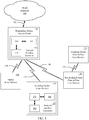
- the communication system can include a plurality of stations (STA) 105-125 communicatively coupled together by one or more wireless communication links 130-145 in a Wireless Local Area Network (WLAN).
- the stations 105-130 can include a computing device in combination with a wireless network interface controller 150, 155.
- the computing devices can be any type of computing device, including but not limited to desktop Personal Computers (PCs), laptop PCs, tablet PCs, printers, smart phones, smart televisions, game consoles, infotainment systems, Internet of Thing (IOT) devices and the like.
- the network interface controller 150 can include one or more processors 160, one or more memories 165, and one or more transceivers 170.
- the memory 165 can store one or more computing device executable instructions and data that when processed by the one or processors 160 implement one or more functions performed by the stations 105-125 as described herein.
- the wireless communication links 130-145 can be compliant with a specified wireless protocol standard. In one implementation, the wireless communication links 130-145 can be compliant with the Institute of Electrical and Electronics Engineering (IEEE) 802.11 standard, commonly referred to as Wi-Fi communication links 130-145.
- IEEE Institute of Electrical and Electronics Engineering
- One or more stations 105 can also be communicatively coupled 175 to one or more Wide Area Networks (WANs) 195 or the like.
- Stations 105 communicatively coupled to one or more WANs 195 by a wired communication link 190 can also be referred to as Access Points (AP).
- An Access Point can connect a group of stations to a wired network 195.
- the Access Point can be a standalone device or be integral with a computing device such as desktop PCs, laptop PCs, tablet PCs, smart phones, routers, modems and the like.
- stations can be communicatively coupled in a Peer-to-Peer
- a number of the stations can be mobile computing devices, such as laptop PCs, tablet PCs, smart phones, infotainment systems, and IOT devices.
- the communication system can implement location services based upon the determination of the distance between stations.
- the location of stations to within ten or less meters, can be determined as a function the time that it takes for the wireless signal to travel from one station to another station.
- a Station can determine the distance between the Station and an Access Point (e.g., a Single User (SU) implementation) as a function the time that it takes for wireless signals to travel between the Station and the Access Point, or between a plurality of Stations and an Access Point (e.g., a Multi-User (MU) implementation).
- a Station can determine the distance between the Station and another Station (e.g., a Single User (SU) implementation) as a function the time that it takes for wireless signals to travel between the Station and the other Station.
- SU Single User
- MU Multi-User
- the method of determining the distance between wireless devices can be implemented as computing device-executable instructions (e.g., computer program) that are stored in the one or more memories 165, 180 (e.g., computing device-readable media) and executed by the one or more processors 160, 175 to control the one or more transceivers 170, 185 in the network interface controller 150, 155 of corresponding stations 105, 115, 120, 125 in accordance with aspects of the present technology.
- computing device-executable instructions e.g., computer program
- memories 165, 180 e.g., computing device-readable media
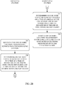
- the method can include an initiating Station (STA) sending a timing measurement request to a responding Station (STA), at 205.
- the responding station can receive the timing measurement request from the initiating Station (STA).
- the initiating Station (STA) can be a mobile client device and the responding Station (STA) can be an Access Point that sends and receives frames using a Wi-Fi communication protocol.
- the initiating Station (STA) can be a first Peer-to-Peer client device and the responding Station (STA) can be a second Peer-to-Peer client device.
- the responding station can send a timing measurement confirmation to the initiating Station (STA).
- the initiating Station can receive the timing measurement confirmation from the responding Station (STA).
- the timing measurement request can include a Wi-Fi initiating Fine Timing Measurement (iFTM) request frame and the timing measurement confirmation can include an initiating Fine Timing Measurement (iFTM) frame.
- iFTM Wi-Fi initiating Fine Timing Measurement
- iFTM initiating Fine Timing Measurement
- the initiating Station (STA) can optionally send one or more uplink Null Data Packet Announcement (NDPA) frames to the responding Station (STA) after receiving the timing measurement confirmation, at 225.
- the responding Station (STA) can receive the optional one or more uplink Null Data Packet Announcement (NDPA) frames from the initiating Station (STA).
- the initiating Station (STA) can send one or more uplink Null Data Packet (NDP) frames to the responding Station (STA), at 235.
- the responding Station (STA) can receive the one or more uplink Null Data Packet (NDP) frames from the initiating Station (STA).
- the responding Station (STA) can send one or more downlink Null Data Packet (NDP) frames to the initiating Station (STA), at 245.
- the initiating Station (STA) can receive the one or more downlink Null Data Packet (NDP) frames from the responding Station (STA).
- the responding Station can determine one or more timing measurements of the one or more uplink and downlink Null Data Packet (NDP) frames.
- the timing measurements determined by the responding Station can include the time-of-arrival of the one or more uplink Null Data Packet (NDP) frames and the time-of-departure of the one or more downlink Null Data Packet (NDP) frames.
- the responding Station (STA) can send one or more Location Measurement Report (LMR) frames including the one or more timing measurements determined by the responding Station (STA).
- the initiating Station (STA) can receive the one or more Location Measurement Report (LMR) frames from the initiating Station (STA).
- NDPA uplink Null Data Packet Announcement
- NDP uplink Null Data Packet
- NDP downlink Null Data Packet
- LMR Location Measurement Report
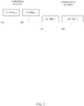
- the one or more optional uplink Null Data Packet Announcement (NDPA) frames, the one or more uplink Null Data Packet (NDP) frames, the one or more downlink Null Data Packet (NDP) frames, and the one or more Location Measurement Report (LMR) frames can be iteratively sent between the initiating and responding Stations (STA).
- STA initiating and responding Stations
- the one or more optional uplink Null Data Packet Announcement (NDPA) frames, the one or more uplink Null Data Packet (NDP) frames, the one or more downlink Null Data Packet (NDP) frames and the one or more Location Measurement Report (LMR) frames exchanged between the initiating and responding Stations (STA) can be transmitted based on a format and bandwidth indicated in the timing measurement request or optionally the timing measurement confirmation exchanged between the initiating Station (STA) and the responding Station (STA).
- NDPA Null Data Packet Announcement
- NDP uplink Null Data Packet
- NDP downlink Null Data Packet
- LMR Location Measurement Report
- the responding Station (STA) should transmit the initiating Fine Timing Measurement (iFTM) frame with the format and bandwidth that it indicated.
- the responding Station (STA) can use a 242-tone or less Resource Unit (RU), a 484-tone or less Resource Unit (RU), 996-tone or less Resource Unit (RU), or 2x996-tone or less Resource Unit (RU) when the bandwidth that the responding Station (STA) indicated is 20 MHz, 40 MHz, 80 MHz or 160 MHz, respectively.
- the responding Station can assign a 242-tone or less Resource Unit (RU), 484-tone or less Resource Unit (RU), 996-tone or less Resource Unit, or 2x996-tone or less Resource Unit (RU) for soliciting a High Efficiency (HE) Multi-User (MU) Physical Layer Convergence Procedure Protocol Data Unit (PPDU) carrying the Acknowledgment (Ack) of the initiating Fine Timing Measurement (iFTM) frame received by the initiating Station (STA) when the bandwidth that the responding Station (STA) indicated is 20 MHz, 40 MHz, 80 MHz, or 160 MHz, respectively.
- HE High Efficiency
- MU Physical Layer Convergence Procedure Protocol Data Unit
- Ack Acknowledgment
- iFTM Fine Timing Measurement
- the bandwidth of the Resource Unit (RU) carry the Acknowledgement (Ack) response of the initiating Fine Timing Measurement (iFTM) frame in the High Efficiency (HE) Trigger-Based (TB) Physical Layer Convergence Procedure Protocol Data Unit (PPDU) should be the same as the bandwidth of the Resource Unit (RU) carrying the High Efficiency (HE) Multi-User (MU) Physical Layer Convergence Procedure Protocol Data Unit (PPDU).
- the responding Station (STA) can also transmit initiating Fine Timing Measurement (iFTM) frame in a High Efficiency (HE) Multi-User (MU) Physical Layer Convergence Procedure Protocol Data Unit (PPDU) using a 26-tone Resource Unit (RU), 52-tone Resource Unit (RU), or 106-tone Resource Unit (RU).
- HE High Efficiency
- MU Multi-User
- PPDU Physical Layer Convergence Procedure Protocol Data Unit
- the initiating Station (STA) does not want to receive the initiating Fine Timing Measurement (iFTM) frame on such a small Resource Unit (e.g., less than 20 MHz)
- the initiating Station (STA) can include a minimum bandwidth information field in the parameter element of the initiating Fine Timing Measurement (iFTM) request frame.
- the minimum bandwidth information field can be set to 0, 1, 2 or 3 to indicating a 26-tone or less Resource Unit (RU), 52-tone or less Resource Unit (RU), 106-tone or less Resource Unit (RU) or 242-tone or less Resource Unit (RU), respectively.
- the responding Station (STA) should not transmit initiating Fine Timing Measurement (iFTM) frames with a bandwidth which is less than the bandwidth that the responding Station (STA) indicated in the minimum bandwidth information field.
- iFTM Fine Timing Measurement
- the responding Station also should not solicit a High Efficiency (HE) Trigger-Based (TB) Physical Layer Convergence Procedure Protocol Data Unit (PPDU) carry the Acknowledgment (Ack) of the received initiating Fine Timing Measurement (iFTM) frame on the Resource Unit (RU) of which the bandwidth is less than the bandwidth that the responding Station (STA) indicated by the minimum bandwidth information field.
- HE High Efficiency
- TB Physical Layer Convergence Procedure Protocol Data Unit
- Ack Acknowledgment
- iFTM Fine Timing Measurement
- RU Resource Unit
- the initiating Station can determine one or more timing measurements of the one or more uplink and downlink Null Data Packet (NDP) frames, at 270.
- the timing measurements determined by the initiating Station (STA) can include the time-of departure of the one or more uplink Null Data Packet (NDP) frames and the time-of-arrival of the one or more downlink Null Data Packet (NDP) frames.
- the initiating Station can determine a distance between the initiating Station (STA) and the responding Station (STA) based on the one or more timing measurements of the uplink and downlink Null Data Packet (NDP) frames received in the one or more Location Measurement Reports (LMR) and the one or more timing measurements of the uplink and downlink Null Data Packet (NDP) frames determined by the initiating Station (STA).
- NDP Null Data Packet
- the initiating Station (STA) can also determine the location of the initiating Station (STA) further based on the shared location of the responding Station (STA) (e.g., latitude and longitude of the Access Point responding Station (STA)), shared height of the responding Station (STA) (e.g., floor number and/or height above the floor), shared neighbor report, Uniform Resource Identifier (URI) or Domain Name in combination with a network mapping, and/or the like.
- STA shared location of the responding Station
- STA shared location of the responding Station
- STA shared height of the responding Station
- URI Uniform Resource Identifier
- Domain Name in combination with a network mapping, and/or the like.
- the method of determining the distance between wireless devices can again be implemented as computing device-executable instructions (e.g., computer program) that are stored in the one or more memories 165, 180 (e.g., computing device-readable media) and executed by the one or more processors 160, 175 to control the one or more transceivers 170, 185 in the network interface controller 150, 155 of corresponding stations 105, 115, 120, 125 in accordance with aspects of the present technology.
- computing device-executable instructions e.g., computer program
- memories 165, 180 e.g., computing device-readable media
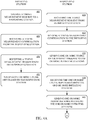
- the method can include an initiating Station (STA) sending a timing measurement request to a responding Station (STA), at 405.
- the responding station can receive the timing measurement request from the initiating Station (STA).
- the responding station can send a timing measurement confirmation to the initiating Station (STA).
- the initiating Station (STA) can receive the timing measurement confirmation from the responding Station (STA).
- the timing measurement request can include a Wi-Fi initiating Fine Timing Measurement (iFTM) request frame and the timing measurement confirmation can include an initiating Fine Timing Measurement (iFTM) frame.
- the responding Station can send one or more groups of timing measurement triggers one or more times to one or more initiating Stations (STA) after sending the timing measurement confirmation, at 425.
- the one or more initiating Stations can receive a timing measurement trigger from the responding Station (STA).
- the initiating Stations (STA) can send corresponding uplink Null Data Packet (NDP) frames one or more times to the responding Station (STA), at 435.
- the responding Station (STA) can receive the uplink Null Data Packet (NDP) frames one or more times from the initiating Stations (STA), at 440.
- the responding Station can send one or more downlink Null Data Packet Announcement (NDPA) frames to the one or more initiating Stations (STA) after receiving the uplink Null Data Packet (NDP) frames one or more times to the one or more initiating Stations (STA), at 445.
- the one or more initiating Stations (STA) can receive the uplink Null Data Packet Announcement (NDPA) frames one or more times from the responding Stations (STA), at 450.
- the responding Station can send one or more downlink Null Data Packet (NDP) frames to the one or more initiating Stations (STA) after sending the downlink Null Data Packet Announcement (NDPA) frames, at 455.
- the initiating Station (STA) can receive the downlink Null Data Packet (NDP) frame from the responding Station (STA), at 460.
- the responding Station can determine one or more timing measurements of the one or more uplink and downlink Null Data Packet (NDP) frames.
- the timing measurements determined by the responding Station can include the time-of-arrival of the one or more uplink Null Data Packet (NDP) frames and the time-of-departure of the one or more downlink Null Data Packet (NDP) frames.
- the responding Station (STA) can send one or more Location Measurement Report (LMR) frames including the one or more timing measurements to the one or more initiating Stations (STA).
- the one or more initiating Stations (STA) can receive the one or more Location Measurement Report (LMR) frames from the responding Station (STA).
- Timing measurement triggers for a group of initiating Stations (STA) can be sent together in a frame. If there is a large number of initiating Stations (STA), groups of timing measurement triggers can be sent in a plurality of frames.
- Corresponding initiating Stations can send uplink Null Data Packet (NDP) frames to the responding Station (STA) in corresponding sets.
- the groups of timing measurement triggers, groups of uplink Null Data Packet (NDP) frames, the downlink Null Data Packet Announcement (NDPA) frames, the downlink Null Data Packet (NDP) frames, and the Location Measurement Report (LMR) frames can be iteratively sent between the initiating and responding Stations (STA).
- the groups of timing measurement triggers, groups of uplink Null Data Packet (NDP) frames, the downlink Null Data Packet Announcement (NDPA) frames, the downlink Null Data Packet (NDP) frames, and the Location Measurement Report (LMR) frames exchanged between the initiating and responding Stations (STA) can be transmitted based on a format and bandwidth indicated in the timing measurement request or optionally the timing measurement confirmation exchanged between the initiating Station (STA) and the responding Station (STA).
- the responding Station (STA) when the responding Station (STA) transmits a trigger frame (e.g., High Efficiency HEz trigger frame), the responding Station (STA) shall not use a bandwidth wider than that indicated in the initiating Fine Timing Measurement (iFTM) request frame. In such case, the responding Station (STA) shall set the transmit vector (TXVECTOR) parameter of the channel bandwidth (CH BANDWIDTH) to the same value as the bandwidth (BW) subfield of the common info field in the trigger frame.
- TXVECTOR transmit vector
- the responding Station (STA) When the responding Station (STA) transmits the Null Data Packet Announcement (NDPA) frames and the downlink Null Data Packet (NDP) frames, after receiving uplink Null Data Packet (NDP) frames from the initiating Station (STA), the responding Station (STA) shall set the transmit vector (TXVECTOR) parameter of the channel bandwidth (CH BANDWIDTH) to the same value as the bandwidth of the trigger and the uplink Null Data Packet (NDP) frames transmitted in a preceding uplink sounding phase.
- the bandwidth (BW) field of the SIG-A field in an uplink Null Data Packet (NDP) frame represents the bandwidth of the uplink Null Data Packet (NDP) frame.
- the bandwidth (BW) field of the SIG-A field in an uplink Null Data Packet (NDP) frame is set to a same bandwidth value indicated in bandwidth (BW) subfield of the common info field in the trigger frame.
- the initiating Station (STA) shall set the transmit vector (TXVECTOR) parameter of the channel bandwidth (CH BANDWIDTH) to the same value as the bandwidth (BW) subfield of the common info field in the trigger frame.
- the responding Station (STA) when the responding Station (STA) is transmitting a trigger frame, the responding Station (STA) can assign a 242-tone or less Resource Unit (RU), a 484-tone or less Resource Unit (RU), a 996-tone or less Resource Unit (RU), or 2x996-tone or less Resource Unit (RU) for soliciting a High Efficiency (HE) Trigger-Based (TB) Physical Layer Convergence Procedure Protocol Data Unit (PPDU) carrying an uplink Null Data Packet (NDP) when the bandwidth that the responding Station (STA) indicated is 20 MHz, 40 MHz, 80 MHz, or 160 MHz, respectively.
- HE High Efficiency
- TB Physical Layer Convergence Procedure Protocol Data Unit
- NDP uplink Null Data Packet
- the responding Station When the responding Station (STA) is transmitting a downlink Null Data Packet Announcement (NDPA) frame and a downlink Null Data Packet (NDP) frame, the responding Station (STA) can set the bandwidth of the downlink Null Data Packet Announcement (NDPA) frame and a downlink Null Data Packet (NDP) frame to the same value as the bandwidth of the downlink trigger frame and the uplink Null Data Packet (NDP) transmitted in a proceeding sounding phase.
- the bandwidth field of the SIG-A field in an uplink Null Data Packet (NDP) frame represent the bandwidth of the uplink Null Data Packet (NDP) frame.
- the responding Station should transmit the downlink Null Data Packet Announcement (NDPA) frame and a downlink Null Data Packet (NDP) frame with the bandwidth that it indicated.
- the initiating Station (STA) can include a minimum bandwidth information field in the parameters element of a initiating Fine Timing Measurement (iFTM) request frame.
- the minimum bandwidth information field can be set to a value of 0, 1, 2 or 3 for indicating a 26-tone or less Resource Unit (RU), 52-tone or less Resource Unit (RU), 106-tone or less Resource Unit (RU), or 242-tone or less Resource Unit (RU), respectively.
- the responding Station should not solicit a High Efficiency (HE) Trigger-Based (TB) Physical Layer Convergence Procedure Protocol Data Unit (PPDU) carrying an uplink Null Data Packet (NDP) on the Resource Unit (RU) of which the bandwidth is less than what the responding Station (STA) indicated in the minimum bandwidth information field.
- HE High Efficiency
- TB Physical Layer Convergence Procedure Protocol Data Unit
- NDP uplink Null Data Packet
- the initiating Station can determine one or more timing measurements of the one or more uplink and downlink Null Data Packet (NDP) frames, at 480.
- the timing measurements determined by the initiating Station (STA) can include the time-of departure of the one or more uplink Null Data Packet (NDP) frames and the time-of-arrival of the one or more downlink Null Data Packet (NDP) frames.
- the initiating Station (STA) can determine a distance between the initiating Station (STA) and the responding Station (STA) based on the one or more timing measurement in the one or more Location Measurement Report (LMR) frames and the one or more timing measurements determined by the initiating Station (STA).
- the initiating Station (STA) can also determine the location of the initiating Station (STA) further based on the shared location of the responding Station (STA) (e.g., latitude and longitude of the Access Point responding Station (STA)), shared height of the responding Station (STA) (e.g., floor number and/or height above the floor), shared neighbor report, Uniform Resource Identifier (URI) or Domain Name in combination with a network mapping, and/or the like.
- STA shared location of the responding Station
- STA shared height of the responding Station
- URI Uniform Resource Identifier
- Domain Name in combination with a network mapping, and/or the like.
- the Enhanced Fine Timing Measurement (EFTM) Wi-Fi method can be implemented as computing device-executable instructions (e.g., computer program) that are stored in the one or more memories 165, 180 (e.g., computing device-readable media) and executed by the one or more processors 160, 175 to control the one or more transceivers 170, 185 in the network interface controller 150, 155 of corresponding stations 105, 115, 120, 125 in accordance with aspects of the present technology.
- the Enhanced Fine Timing Measurement (EFTM) can be based on Null Data Packet Announcement (NDPA) and Null Data Packet (NDP) frames of the Wi-Fi protocol.
- the Enhanced Fine Timing Measurement can be initiated by a first Station, referred to as an initiating Station (STA), sending an initiating Fine Timing Measurement (iFTM) request frame to a second Station, referred to as a responding Station (STA), at 605.
- the initiating Station can be a user device 115 and the responding Station (STA) can be an Access Point 105, as illustrated in FIG. 1 .
- the initiating Station can be a first user device 125 and the responding Station (STA) can be a second user device 120, as illustrated in FIG. 1 .
- the initiating Fine Timing Measurement (iFTM) request frame can include one or more measurement parameters including a format and bandwidth field.
- the initiating Station (STA) can indicate a requested format and bandwidth that it supports in the measurement parameters of the initiating Fine Timing Measurement (iFTM) request frame.
- the exemplary format and bandwidth field values in Table 1 can specify various formats and bandwidths.
- the responding Station (STA) can send an Acknowledgement frame to the initiating Station (STA) in response to receipt of the initiating Fine Timing Measurement (iFTM) request frame.
- the responding Station (STA) can send an initiating Fine Timing Measurement (FTM) frame to the initiating Station (STA) after sending the Acknowledgement frame.
- the responding Station (STA) can indicate the same format and bandwidth in the initiating Fine Timing Measurement (FTM) frame as that requested by the initiating Station (STA), if the responding Station (STA) supports the indicated format and bandwidth.
- the responding Station (STA) can indicate a format and a bandwidth supported by the responding Station (STA), wherein the indicated bandwidth is not wider that the bandwidth requested by the initiating Station (STA).
- the responding Station (STA) shall not indicate an Enhanced Fine Timing Measurement (EFTM) format if the initiating Station (STA) requested a DMG, HE, VHT, HT-Mixed or Non-HT format.
- the responding Station (STA) shall not indicate an HE format if the initiating Station (STA) requested a DMG, VHT, HT-mixed or Non-HT format.
- EFTM Enhanced Fine Timing Measurement
- the responding Station (STA) shall also not indicate a HT format if the initiating Station (STA) requested a DMG or Non-HT format.
- the responding Station (STA) shall also not indicate a DMG format if the initiating Station (STA) requested an EFTM, HE, VHT, HT-mixed or Non-HT format.
- the responding Station (STA) shall not indicate a HE MU format if the initiating Station (STA) indicated and HE SU, HE ER SU, VHT or HT-Mixed on Non-HT format.
- the responding Station (STA) shall also not indicate and HE SU, HE ER SU, VHT or HT-mixed or non-HT format if the initiating Station (STA) indicated and HE MU format.
- the initiating Station (STA) can send an Acknowledgment frame to the responding Station (STA) in response to receipt of the initial Fine Timing Measurement (FTM) frame.
- the initiating Station (STA) can also send a first uplink Null Data Packet Announcement (NDPA) frame to the responding Station (STA) in response to receipt of the initial Fine Timing Measurement (FTM) frame.
- the initiating Station (STA) can also send a first uplink Null Data Packet (NDP) frame to the responding Station (STA) after sending the first uplink Null Data Packet Announcement (NDPA) frame.
- the initiating Station can send the uplink Null Data Packet Announcement (NDPA) frame and the uplink Null Data Packet (NDP) frame using the format and bandwidth indicated by the responding Station (STA) in the initiating Fine Timing Measurement (iFTM) frame.
- NDPA Null Data Packet Announcement
- NDP uplink Null Data Packet
- iFTM Fine Timing Measurement
- the responding Station can send a first downlink Null Data Packet (NDP) frame to the initiating Station (STA) in response to receipt of the first uplink Null Data Packet (NDP) frame.
- the responding Station can also send a first Location Measurement Report (LMR) to the Initiating Station after sending the first downlink Null Data Packet (NDP) frame.
- the responding Station (STA) can send the downlink Null Data Packet (NDP) frame and the Location Measurement Report (LMR) using the format and bandwidth indicated by the responding Station (STA) in the initiating Fine Timing Measurement (iFTM) frame.
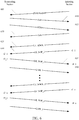
- the Location Measurement Report can include a responding station timing measurement based on the time-of-arrival (t2_1) of the uplink Null Data Packet (NDP) frame and the time-of-departure (t3_1) of the downlink Null Data Packet (NDP) frame.
- the processes a 625-640 can be repeated in one or more additional sounding phases to generate one or more additional sets of uplink Null Data Packet Announcement (NDPA) frames and uplink Null Data Packet (NDP) frames sent from the initiating Station (STA) to the responding Station (STA), and downlink Null Data Packet (NDP) frames and Location Measurement Reports (LMRs) sent from the responding Station (STA) to the initiating Station (STA).
- NDPA uplink Null Data Packet Announcement
- NDP uplink Null Data Packet
- NDP downlink Null Data Packet
- LMRs Location Measurement Reports
- the distance between the initiating Station (STA) and the responding Station (STA) can be determined based the time-of-departure and time-of arrival of one or more sets of uplink and downlink Null Data Packet (NDP) frames.
- the distance between the initiating Station (STA) and the responding Station (STA) can then be determined based upon the Round Trip Time (RTT).
- the location of the initiating Station (STA) can also be determined further based on the shared location of the responding Station (STA) (e.g., latitude and longitude of the Access Point responding Station (STA)), shared height of the responding Station (STA) (e.g., floor number and/or height above the floor), shared neighbor report, Uniform Resource Identifier (URI) or Domain Name in combination with a network mapping, and/or the like.
- STA shared location of the responding Station
- STA shared height of the responding Station
- URI Uniform Resource Identifier
- Domain Name in combination with a network mapping, and/or the like.
- Location services derived from the distance measurement can advantageously be used for advertising and marketing, stopping consumer from getting lost, tracking equipment, and the like.
- hyperlocal marketing can be used by businesses to send targeted ads or special offers to consumers' smart phones as they move through stores and shopping centers.
- location services can support application to assist in finding a conference room in a building, an appointment room in a hospital, a gate or concession stand in an airport, or the like.
- Location services can advantageously leverage ubiquitous WLAN infrastructure deployments, such as Wi-Fi networks, to deliver position data without the need to deploy separate or proprietary infrastructure such as Wi-Fi network beacons.
- WLAN networks, such as Wi-Fi networks advantageously work well indoors, where Global Position Satellite (GPS) signals and cellular telephone signals can be weak.
- GPS Global Position Satellite
- the network-based location services in accordance with aspects of the present technology can advantageously provide location service within structures, wherein GPS and cellular network-based location services may not work well.
Landscapes
- Engineering & Computer Science (AREA)
- Computer Networks & Wireless Communication (AREA)
- Signal Processing (AREA)
- Physics & Mathematics (AREA)
- General Physics & Mathematics (AREA)
- Radar, Positioning & Navigation (AREA)
- Remote Sensing (AREA)
- Mobile Radio Communication Systems (AREA)
Abstract
Description
- This application claims the benefit of
U.S. Provisional Patent Application No. 62/552,429 filed August 31, 2018 - Computing systems have made significant contributions toward the advancement of modern society and are utilized in a number of applications to achieve advantageous results. Numerous devices, such as desktop personal computers (PCs), laptop PCs, tablet PCs, netbooks, smart phones, servers, and the like have facilitated increased productivity and reduced costs in communicating and analyzing data in most areas of entertainment, education, business, and science. One common aspect of computing systems is the wireless networking of mobile devices. The Wireless networks can provide for determining the location of one or more devices in the network for use in applications such as advertising and marketing, stopping consumer from getting lost, tracking equipment, and the like.
- Cellular telephone networks can utilize triangulation based on Global Position Satellite (GPS) signals, cell tower signals or a combination thereof to determine the location of user devices. However, GPS signals and cell tower signals can be relatively weak inside structures making the signals difficult to use to determine the location of a cellular and/or GPS enabled user device. Wi-Fi enabled devices can use beacon signals or timing measurement frames to determine the location of devices in the Wi-Fi network. The use of beacons however can be relatively expensive because multiple beacons are needed to cover a given area. The use of timing measurement frames in determining the position, location, distance, range measurement of the like of a Wi-Fi enable device to one or more other devices does not require the use of beacons. However, the current timing measurement frame based techniques can limit how accurately the position of a device can be determined and/or can be processing intensive. Accordingly, there is a continuing need for enhanced location determination techniques for use by mobile wireless network devices.
- The present technology may best be understood by referring to the following description and accompanying drawings that are used to illustrate embodiments of the present technology directed toward techniques for determining a distance between devices based on timing measurements of one or more sets of Null Data Packet (NDP) frames exchanged between network devices.
- In one aspect, a method of determining a distance between wireless devices can include transmitting a timing measurement request from an initiating Station (STA) to a responding Station (STA). The timing measurement request can include a request of a frame format and bandwidth supported by the initiating Station (STA). A timing measurement confirmation can be transmitted from the responding Station (STA) to the initiating Station (STA), wherein the timing measurement confirmation includes an indication of a frame format and bandwidth supported by the Requesting Station having a bandwidth that is no more than the requested frame format and bandwidth supported by the initiating Station (STA). One or more uplink Null Data Packet (NDP) frames can be transmitted from the initiating Station (STA) to the responding Station (STA) using the frame format and bandwidth supported by the Requesting Station. In addition, one or more downlink Null Data Packet (NDP) frames and one or more Location Measurement Report (LMR) frames can be transmitted, iteratively with the uplink Null Data Packet (NDP) frames, from the initiating Station (STA) to the responding Station (STA). The downlink Null Data Packet (NDP) frames and Location Measurement Reports (LMR) frames can also have the frame format and bandwidth supported by the Requesting Station. The Location Measurement Report (LMR) frames can include one or more timing measurements of the uplink and downlink Null Data Packet (NDP) determined by the responding Station (STA). The initiating Station (STA) can also determine one or more timing measurements of the uplink and downlink Null Data Packet (NDP) frames. The initiating Station (STA) can then determine a distance between the initiating Station (STA) and the responding Station (STA) based on the one or more timing measurements of the uplink and downlink Null Data Packet (NDP) frames received in the one or more Location Measurement Reports (LMR) and determined by the initiating Station (STA). The one or more timing measurement of the uplink and downlink Null Data Packet (NDP) frames can include the time-of-departure from the initiating Station (STA) of the one or more uplink Null Data Packet (NDP) frames, the time-of-arrival at the responding Station (STA) of the one or more uplink Null Data Packet (NDP) frames, the time-of-departure from the responding Station (STA) of the one or more downlink Null Data Packet (NDP) frames, and the time-of-arrival at the initiating Station (STA) of the one or more downlink Null Data Packet (NDP) frames.
- In another aspect, a method of determining a distance between wireless devices can include transmitting a timing measurement request from an initiating Station (STA) to a responding Station (STA). The timing measurement request can include a request of a frame format and bandwidth supported by the initiating Station (STA). A timing measurement confirmation can be transmitted from the responding Station (STA) to the initiating Station (STA), wherein the timing measurement confirmation includes an indication of a frame format and bandwidth supported by the Requesting Station having a bandwidth that is no more than the requested frame format and bandwidth supported by the initiating Station (STA). A group of timing measurement triggers can be sent form the responding Station (STA) to a set of initiating Stations (STA) using the frame format and bandwidth supported by the Requesting Station. One or more of a set of uplink Null Data Packet (NDP) frames can be transmitted from the set of initiating Stations (STA) to the responding Station (STA) using the frame format and bandwidth supported by the Requesting Station. Multiple sets of frames including groups of triggers and multiple set of uplink Null Data Packet (NDP) frames can be exchanged between the responding Station (STA) and the initiating Stations (STA) to support a large number of initiating Stations (STA). One or more downlink Null Data Packet (NDP) frames and one or more Location Measurement Report (LMR) frames can be transmitted from the responding Station (STA) to the initiating Station (STA) using the frame format and bandwidth supported by the Requesting Station. The Location Measurement Report (LMR) frames can include one or more timing measurements of the uplink and downlink Null Data Packet (NDP) determined by the responding Station (STA). The initiating Station (STA) can also determine one or more timing measurements of the uplink and downlink Null Data Packet (NDP) frames. The initiating Station (STA) can again determine a distance between the initiating Station (STA) and the responding Station (STA) based on the one or more timing measurements of the uplink and downlink Null Data Packet (NDP) frames received in the one or more Location Measurement Reports (LMR) and determined by the initiating Station (STA).
- This Summary is provided to introduce a selection of concepts in a simplified form that are further described below in the Detailed Description. This Summary is not intended to identify key features or essential features of the claimed subject matter, nor is it intended to be used to limit the scope of the claimed subject matter.
- Embodiments of the present technology are illustrated by way of example and not by way of limitation, in the figures of the accompanying drawings and in which like reference numerals refer to similar elements and in which:
-
FIG. 1 shows a communication system, in accordance with aspects of the present technology. -
FIGS. 2A ,2B and2C show a method of determining a distance between wireless devices, in accordance with aspects of the present technology. -
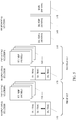
FIG. 3 illustrates an exemplary exchange of a set of an uplink Null Data Packet Announcement (NDPA) frame, an uplink Null Data Packet (NDP) frame, a downlink Null Data Packet (NDP) frame, and a Location Measurement Report (LMR) frame. -
FIGS. 4A ,4B and4C show a method of determining a distance between wireless devices, in accordance with aspects of the present technology. -
FIG. 5 illustrates an exemplary exchange of one or more sets of groups of timing measurement triggers, groups uplink Null Data Packet Announcement (NDPA) frames and an uplink Null Data Packet (NDP) frames, a downlink Null Data Packet Announcement (NDPA) frame, a downlink Null Data Packet (NDP) frame, and a Location Measurement Report (LMR) frame. -
FIG. 6 shows an Enhanced Fine Timing Measurement (EFTM) Wi-Fi method, in accordance with aspects of the present technology. - Reference will now be made in detail to the embodiments of the present technology, examples of which are illustrated in the accompanying drawings. While the present technology will be described in conjunction with these embodiments, it will be understood that they are not intended to limit the invention to these embodiments. On the contrary, the invention is intended to cover alternatives, modifications and equivalents, which may be included within the scope of the invention as defined by the appended claims. Furthermore, in the following detailed description of the present technology, numerous specific details are set forth in order to provide a thorough understanding of the present technology. However, it is understood that the present technology may be practiced without these specific details. In other instances, well-known methods, procedures, components, and circuits have not been described in detail as not to unnecessarily obscure aspects of the present technology.
- Some embodiments of the present technology which follow are presented in terms of routines, modules, logic blocks, and other symbolic representations of operations on data within one or more electronic devices. The descriptions and representations are the means used by those skilled in the art to most effectively convey the substance of their work to others skilled in the art. A routine, module, logic block and/or the like, is herein, and generally, conceived to be a self-consistent sequence of processes or instructions leading to a desired result. The processes are those including physical manipulations of physical quantities. Usually, though not necessarily, these physical manipulations take the form of electric or magnetic signals capable of being stored, transferred, compared and otherwise manipulated in an electronic device. For reasons of convenience, and with reference to common usage, these signals are referred to as data, bits, values, elements, symbols, characters, terms, numbers, strings, and/or the like with reference to embodiments of the present technology.
- It should be borne in mind, however, that all of these terms are to be interpreted as referencing physical manipulations and quantities and are merely convenient labels and are to be interpreted further in view of terms commonly used in the art. Unless specifically stated otherwise as apparent from the following discussion, it is understood that through discussions of the present technology, discussions utilizing the terms such as "receiving," and/or the like, refer to the actions and processes of an electronic device such as an electronic computing device that manipulates and transforms data. The data is represented as physical (e.g., electronic) quantities within the electronic device's logic circuits, registers, memories and/or the like, and is transformed into other data similarly represented as physical quantities within the electronic device.
- In this application, the use of the disjunctive is intended to include the conjunctive. The use of definite or indefinite articles is not intended to indicate cardinality. In particular, a reference to "the" object or "a" object is intended to denote also one of a possible plurality of such objects. It is also to be understood that the phraseology and terminology used herein is for the purpose of description and should not be regarded as limiting.
- Referring to
FIG. 1 , a communication system, in accordance with aspects of the present technology is shown. The communication system can include a plurality of stations (STA) 105-125 communicatively coupled together by one or more wireless communication links 130-145 in a Wireless Local Area Network (WLAN). The stations 105-130 can include a computing device in combination with a wirelessnetwork interface controller network interface controller 150 can include one ormore processors 160, one ormore memories 165, and one ormore transceivers 170. Thememory 165 can store one or more computing device executable instructions and data that when processed by the one orprocessors 160 implement one or more functions performed by the stations 105-125 as described herein. The wireless communication links 130-145 can be compliant with a specified wireless protocol standard. In one implementation, the wireless communication links 130-145 can be compliant with the Institute of Electrical and Electronics Engineering (IEEE) 802.11 standard, commonly referred to as Wi-Fi communication links 130-145. - One or
more stations 105 can also be communicatively coupled 175 to one or more Wide Area Networks (WANs) 195 or the like.Stations 105 communicatively coupled to one ormore WANs 195 by a wiredcommunication link 190 can also be referred to as Access Points (AP). An Access Point can connect a group of stations to awired network 195. The Access Point can be a standalone device or be integral with a computing device such as desktop PCs, laptop PCs, tablet PCs, smart phones, routers, modems and the like. In addition, stations can be communicatively coupled in a Peer-to-Peer - A number of the stations can be mobile computing devices, such as laptop PCs, tablet PCs, smart phones, infotainment systems, and IOT devices. In aspects, the communication system can implement location services based upon the determination of the distance between stations. The location of stations, to within ten or less meters, can be determined as a function the time that it takes for the wireless signal to travel from one station to another station. In an Access Point implementation, a Station can determine the distance between the Station and an Access Point (e.g., a Single User (SU) implementation) as a function the time that it takes for wireless signals to travel between the Station and the Access Point, or between a plurality of Stations and an Access Point (e.g., a Multi-User (MU) implementation). In a Peer-to-Peer implementation, a Station can determine the distance between the Station and another Station (e.g., a Single User (SU) implementation) as a function the time that it takes for wireless signals to travel between the Station and the other Station.
- Referring now to
FIGS. 2A-2C , a method of determining a distance between wireless devices, in accordance with aspects of the present technology is shown. The method of determining the distance between wireless devices can be implemented as computing device-executable instructions (e.g., computer program) that are stored in the one ormore memories 165, 180 (e.g., computing device-readable media) and executed by the one ormore processors more transceivers network interface controller stations - The method can include an initiating Station (STA) sending a timing measurement request to a responding Station (STA), at 205. At 210, the responding station can receive the timing measurement request from the initiating Station (STA). In an Access Point implementation, the initiating Station (STA) can be a mobile client device and the responding Station (STA) can be an Access Point that sends and receives frames using a Wi-Fi communication protocol. In a Peer-to-Peer implementation, the initiating Station (STA) can be a first Peer-to-Peer client device and the responding Station (STA) can be a second Peer-to-Peer client device. At 215, the responding station can send a timing measurement confirmation to the initiating Station (STA). At 220, the initiating Station (STA) can receive the timing measurement confirmation from the responding Station (STA). In one implementation, the timing measurement request can include a Wi-Fi initiating Fine Timing Measurement (iFTM) request frame and the timing measurement confirmation can include an initiating Fine Timing Measurement (iFTM) frame.
- The initiating Station (STA) can optionally send one or more uplink Null Data Packet Announcement (NDPA) frames to the responding Station (STA) after receiving the timing measurement confirmation, at 225. At 230, the responding Station (STA) can receive the optional one or more uplink Null Data Packet Announcement (NDPA) frames from the initiating Station (STA).
- After sending the timing measurement confirmation and each of the one or more optional uplink Null Data Packet Announcement (NDPA) frames, the initiating Station (STA) can send one or more uplink Null Data Packet (NDP) frames to the responding Station (STA), at 235. At 240, the responding Station (STA) can receive the one or more uplink Null Data Packet (NDP) frames from the initiating Station (STA). In response to receipt of the uplink Null Data Packet (NDP) frames, the responding Station (STA) can send one or more downlink Null Data Packet (NDP) frames to the initiating Station (STA), at 245. At 250, the initiating Station (STA) can receive the one or more downlink Null Data Packet (NDP) frames from the responding Station (STA).
- At 255, the responding Station (STA) can determine one or more timing measurements of the one or more uplink and downlink Null Data Packet (NDP) frames. In one implementation, the timing measurements determined by the responding Station (STA) can include the time-of-arrival of the one or more uplink Null Data Packet (NDP) frames and the time-of-departure of the one or more downlink Null Data Packet (NDP) frames. At 260, the responding Station (STA) can send one or more Location Measurement Report (LMR) frames including the one or more timing measurements determined by the responding Station (STA). At 265, the initiating Station (STA) can receive the one or more Location Measurement Report (LMR) frames from the initiating Station (STA).
- Referring now to
FIG. 3 an exemplary exchange of a set of an uplink Null Data Packet Announcement (NDPA)frame 310, an uplink Null Data Packet (NDP)frame 320, a downlink Null Data Packet (NDP)frame 330, and a Location Measurement Report (LMR)frame 340 is illustrated. The one or more optional uplink Null Data Packet Announcement (NDPA) frames, the one or more uplink Null Data Packet (NDP) frames, the one or more downlink Null Data Packet (NDP) frames, and the one or more Location Measurement Report (LMR) frames can be iteratively sent between the initiating and responding Stations (STA). The one or more optional uplink Null Data Packet Announcement (NDPA) frames, the one or more uplink Null Data Packet (NDP) frames, the one or more downlink Null Data Packet (NDP) frames and the one or more Location Measurement Report (LMR) frames exchanged between the initiating and responding Stations (STA) can be transmitted based on a format and bandwidth indicated in the timing measurement request or optionally the timing measurement confirmation exchanged between the initiating Station (STA) and the responding Station (STA). - In one implementation, the responding Station (STA) should transmit the initiating Fine Timing Measurement (iFTM) frame with the format and bandwidth that it indicated. The responding Station (STA) can use a 242-tone or less Resource Unit (RU), a 484-tone or less Resource Unit (RU), 996-tone or less Resource Unit (RU), or 2x996-tone or less Resource Unit (RU) when the bandwidth that the responding Station (STA) indicated is 20 MHz, 40 MHz, 80 MHz or 160 MHz, respectively. The responding Station (STA) can assign a 242-tone or less Resource Unit (RU), 484-tone or less Resource Unit (RU), 996-tone or less Resource Unit, or 2x996-tone or less Resource Unit (RU) for soliciting a High Efficiency (HE) Multi-User (MU) Physical Layer Convergence Procedure Protocol Data Unit (PPDU) carrying the Acknowledgment (Ack) of the initiating Fine Timing Measurement (iFTM) frame received by the initiating Station (STA) when the bandwidth that the responding Station (STA) indicated is 20 MHz, 40 MHz, 80 MHz, or 160 MHz, respectively. The bandwidth of the Resource Unit (RU) carry the Acknowledgement (Ack) response of the initiating Fine Timing Measurement (iFTM) frame in the High Efficiency (HE) Trigger-Based (TB) Physical Layer Convergence Procedure Protocol Data Unit (PPDU) should be the same as the bandwidth of the Resource Unit (RU) carrying the High Efficiency (HE) Multi-User (MU) Physical Layer Convergence Procedure Protocol Data Unit (PPDU).
- In one implementation, the responding Station (STA) can also transmit initiating Fine Timing Measurement (iFTM) frame in a High Efficiency (HE) Multi-User (MU) Physical Layer Convergence Procedure Protocol Data Unit (PPDU) using a 26-tone Resource Unit (RU), 52-tone Resource Unit (RU), or 106-tone Resource Unit (RU). However, if the initiating Station (STA) does not want to receive the initiating Fine Timing Measurement (iFTM) frame on such a small Resource Unit (e.g., less than 20 MHz), the initiating Station (STA) can include a minimum bandwidth information field in the parameter element of the initiating Fine Timing Measurement (iFTM) request frame. In an exemplary implementation, the minimum bandwidth information field can be set to 0, 1, 2 or 3 to indicating a 26-tone or less Resource Unit (RU), 52-tone or less Resource Unit (RU), 106-tone or less Resource Unit (RU) or 242-tone or less Resource Unit (RU), respectively. In such case, the responding Station (STA) should not transmit initiating Fine Timing Measurement (iFTM) frames with a bandwidth which is less than the bandwidth that the responding Station (STA) indicated in the minimum bandwidth information field. The responding Station (STA) also should not solicit a High Efficiency (HE) Trigger-Based (TB) Physical Layer Convergence Procedure Protocol Data Unit (PPDU) carry the Acknowledgment (Ack) of the received initiating Fine Timing Measurement (iFTM) frame on the Resource Unit (RU) of which the bandwidth is less than the bandwidth that the responding Station (STA) indicated by the minimum bandwidth information field.
- Referring again to
FIG. 2B , the initiating Station (STA) can determine one or more timing measurements of the one or more uplink and downlink Null Data Packet (NDP) frames, at 270. In one implementation, the timing measurements determined by the initiating Station (STA) can include the time-of departure of the one or more uplink Null Data Packet (NDP) frames and the time-of-arrival of the one or more downlink Null Data Packet (NDP) frames. At 275, the initiating Station (STA) can determine a distance between the initiating Station (STA) and the responding Station (STA) based on the one or more timing measurements of the uplink and downlink Null Data Packet (NDP) frames received in the one or more Location Measurement Reports (LMR) and the one or more timing measurements of the uplink and downlink Null Data Packet (NDP) frames determined by the initiating Station (STA). The initiating Station (STA) can also determine the location of the initiating Station (STA) further based on the shared location of the responding Station (STA) (e.g., latitude and longitude of the Access Point responding Station (STA)), shared height of the responding Station (STA) (e.g., floor number and/or height above the floor), shared neighbor report, Uniform Resource Identifier (URI) or Domain Name in combination with a network mapping, and/or the like. - Referring now to
FIGS. 4A-4C , a method of determining a distance between wireless devices, in accordance with aspects of the present technology is shown. The method of determining the distance between wireless devices can again be implemented as computing device-executable instructions (e.g., computer program) that are stored in the one ormore memories 165, 180 (e.g., computing device-readable media) and executed by the one ormore processors more transceivers network interface controller stations - The method can include an initiating Station (STA) sending a timing measurement request to a responding Station (STA), at 405. At 410, the responding station can receive the timing measurement request from the initiating Station (STA). At 415, the responding station can send a timing measurement confirmation to the initiating Station (STA). At 420, the initiating Station (STA) can receive the timing measurement confirmation from the responding Station (STA). In one implementation, the timing measurement request can include a Wi-Fi initiating Fine Timing Measurement (iFTM) request frame and the timing measurement confirmation can include an initiating Fine Timing Measurement (iFTM) frame.
- The responding Station (STA) can send one or more groups of timing measurement triggers one or more times to one or more initiating Stations (STA) after sending the timing measurement confirmation, at 425. At 430, the one or more initiating Stations (STA) can receive a timing measurement trigger from the responding Station (STA).
- The initiating Stations (STA) can send corresponding uplink Null Data Packet (NDP) frames one or more times to the responding Station (STA), at 435. The responding Station (STA) can receive the uplink Null Data Packet (NDP) frames one or more times from the initiating Stations (STA), at 440.
- The responding Station (STA) can send one or more downlink Null Data Packet Announcement (NDPA) frames to the one or more initiating Stations (STA) after receiving the uplink Null Data Packet (NDP) frames one or more times to the one or more initiating Stations (STA), at 445. The one or more initiating Stations (STA) can receive the uplink Null Data Packet Announcement (NDPA) frames one or more times from the responding Stations (STA), at 450.
- The responding Station (STA) can send one or more downlink Null Data Packet (NDP) frames to the one or more initiating Stations (STA) after sending the downlink Null Data Packet Announcement (NDPA) frames, at 455. The initiating Station (STA) can receive the downlink Null Data Packet (NDP) frame from the responding Station (STA), at 460.
- At 465, the responding Station (STA) can determine one or more timing measurements of the one or more uplink and downlink Null Data Packet (NDP) frames. In one implementation, the timing measurements determined by the responding Station (STA) can include the time-of-arrival of the one or more uplink Null Data Packet (NDP) frames and the time-of-departure of the one or more downlink Null Data Packet (NDP) frames. At 470, the responding Station (STA) can send one or more Location Measurement Report (LMR) frames including the one or more timing measurements to the one or more initiating Stations (STA). At 475, the one or more initiating Stations (STA) can receive the one or more Location Measurement Report (LMR) frames from the responding Station (STA).
- Referring now to
FIG. 5 an exemplary exchange of one or more sets of groups of timing measurement triggers 510, 520, one or more sets of groups of uplink Null Data Packet (NDP) frames 530, 540, a downlink Null Data Packet Announcement (NDPA)frame 550, a downlink Null Data Packet (NDP)frame 560, and a Location Measurement Report (LMR)frame 570 is illustrated. Timing measurement triggers for a group of initiating Stations (STA) can be sent together in a frame. If there is a large number of initiating Stations (STA), groups of timing measurement triggers can be sent in a plurality of frames. Corresponding initiating Stations (STA) can send uplink Null Data Packet (NDP) frames to the responding Station (STA) in corresponding sets. The groups of timing measurement triggers, groups of uplink Null Data Packet (NDP) frames, the downlink Null Data Packet Announcement (NDPA) frames, the downlink Null Data Packet (NDP) frames, and the Location Measurement Report (LMR) frames can be iteratively sent between the initiating and responding Stations (STA). The groups of timing measurement triggers, groups of uplink Null Data Packet (NDP) frames, the downlink Null Data Packet Announcement (NDPA) frames, the downlink Null Data Packet (NDP) frames, and the Location Measurement Report (LMR) frames exchanged between the initiating and responding Stations (STA) can be transmitted based on a format and bandwidth indicated in the timing measurement request or optionally the timing measurement confirmation exchanged between the initiating Station (STA) and the responding Station (STA). - In one implementation, when the responding Station (STA) transmits a trigger frame (e.g., High Efficiency HEz trigger frame), the responding Station (STA) shall not use a bandwidth wider than that indicated in the initiating Fine Timing Measurement (iFTM) request frame. In such case, the responding Station (STA) shall set the transmit vector (TXVECTOR) parameter of the channel bandwidth (CH BANDWIDTH) to the same value as the bandwidth (BW) subfield of the common info field in the trigger frame. When the responding Station (STA) transmits the Null Data Packet Announcement (NDPA) frames and the downlink Null Data Packet (NDP) frames, after receiving uplink Null Data Packet (NDP) frames from the initiating Station (STA), the responding Station (STA) shall set the transmit vector (TXVECTOR) parameter of the channel bandwidth (CH BANDWIDTH) to the same value as the bandwidth of the trigger and the uplink Null Data Packet (NDP) frames transmitted in a preceding uplink sounding phase. The bandwidth (BW) field of the SIG-A field in an uplink Null Data Packet (NDP) frame represents the bandwidth of the uplink Null Data Packet (NDP) frame. The bandwidth (BW) field of the SIG-A field in an uplink Null Data Packet (NDP) frame is set to a same bandwidth value indicated in bandwidth (BW) subfield of the common info field in the trigger frame. When the initiating Station (STA) transmits uplink Null Data Packet (NDP) frames , as a response to the trigger frame, the initiating Station (STA) shall set the transmit vector (TXVECTOR) parameter of the channel bandwidth (CH BANDWIDTH) to the same value as the bandwidth (BW) subfield of the common info field in the trigger frame.
- In one implementation, when the responding Station (STA) is transmitting a trigger frame, the responding Station (STA) can assign a 242-tone or less Resource Unit (RU), a 484-tone or less Resource Unit (RU), a 996-tone or less Resource Unit (RU), or 2x996-tone or less Resource Unit (RU) for soliciting a High Efficiency (HE) Trigger-Based (TB) Physical Layer Convergence Procedure Protocol Data Unit (PPDU) carrying an uplink Null Data Packet (NDP) when the bandwidth that the responding Station (STA) indicated is 20 MHz, 40 MHz, 80 MHz, or 160 MHz, respectively. When the responding Station (STA) is transmitting a downlink Null Data Packet Announcement (NDPA) frame and a downlink Null Data Packet (NDP) frame, the responding Station (STA) can set the bandwidth of the downlink Null Data Packet Announcement (NDPA) frame and a downlink Null Data Packet (NDP) frame to the same value as the bandwidth of the downlink trigger frame and the uplink Null Data Packet (NDP) transmitted in a proceeding sounding phase. In one implementation, the bandwidth field of the SIG-A field in an uplink Null Data Packet (NDP) frame represent the bandwidth of the uplink Null Data Packet (NDP) frame. The responding Station should transmit the downlink Null Data Packet Announcement (NDPA) frame and a downlink Null Data Packet (NDP) frame with the bandwidth that it indicated.
- In one implementation, if the initiating Station (STA) does not want to transmit an uplink Null Data Packet (NDP) on a small Resource Unit (RU) (e.g., less than 20 MHz), the initiating Station (STA) can include a minimum bandwidth information field in the parameters element of a initiating Fine Timing Measurement (iFTM) request frame. In an exemplary implementation, the minimum bandwidth information field can be set to a value of 0, 1, 2 or 3 for indicating a 26-tone or less Resource Unit (RU), 52-tone or less Resource Unit (RU), 106-tone or less Resource Unit (RU), or 242-tone or less Resource Unit (RU), respectively. The responding Station (STA) should not solicit a High Efficiency (HE) Trigger-Based (TB) Physical Layer Convergence Procedure Protocol Data Unit (PPDU) carrying an uplink Null Data Packet (NDP) on the Resource Unit (RU) of which the bandwidth is less than what the responding Station (STA) indicated in the minimum bandwidth information field.
- Referring again to
FIG. 4C , the initiating Station (STA) can determine one or more timing measurements of the one or more uplink and downlink Null Data Packet (NDP) frames, at 480. In one implementation, the timing measurements determined by the initiating Station (STA) can include the time-of departure of the one or more uplink Null Data Packet (NDP) frames and the time-of-arrival of the one or more downlink Null Data Packet (NDP) frames. At 485, the initiating Station (STA) can determine a distance between the initiating Station (STA) and the responding Station (STA) based on the one or more timing measurement in the one or more Location Measurement Report (LMR) frames and the one or more timing measurements determined by the initiating Station (STA). The initiating Station (STA) can also determine the location of the initiating Station (STA) further based on the shared location of the responding Station (STA) (e.g., latitude and longitude of the Access Point responding Station (STA)), shared height of the responding Station (STA) (e.g., floor number and/or height above the floor), shared neighbor report, Uniform Resource Identifier (URI) or Domain Name in combination with a network mapping, and/or the like. - Referring now to
FIG. 6 , an Enhanced Fine Timing Measurement (EFTM) Wi-Fi method, in accordance with aspects of the present technology is shown. The Enhanced Fine Timing Measurement (EFTM) Wi-Fi method can be implemented as computing device-executable instructions (e.g., computer program) that are stored in the one ormore memories 165, 180 (e.g., computing device-readable media) and executed by the one ormore processors more transceivers network interface controller stations - The Enhanced Fine Timing Measurement (EFTM) can be initiated by a first Station, referred to as an initiating Station (STA), sending an initiating Fine Timing Measurement (iFTM) request frame to a second Station, referred to as a responding Station (STA), at 605. In an access point implementation, the initiating Station (STA) can be a
user device 115 and the responding Station (STA) can be anAccess Point 105, as illustrated inFIG. 1 . In a peer-to-peer implementation, the initiating Station (STA) can be afirst user device 125 and the responding Station (STA) can be asecond user device 120, as illustrated inFIG. 1 . The initiating Fine Timing Measurement (iFTM) request frame can include one or more measurement parameters including a format and bandwidth field. The initiating Station (STA) can indicate a requested format and bandwidth that it supports in the measurement parameters of the initiating Fine Timing Measurement (iFTM) request frame. In one implementation, the exemplary format and bandwidth field values in Table 1 can specify various formats and bandwidths.Table 1 Field Value Format Bandwidth (MHz) 0 No Preference No Preference 1-3 Reserved Reserved 4 Non-HT 5 5 Reserved Reserved 6 Non-HT 10 7 Reserved Reserved 8 Non-HT Excluding Clause 15 and 16 20 9 HT Mixed 20 10 VHT 20 11 HT Mixed 40 12 VHT 40 13 VHT 80 14 VHT 80+80 15 VHT (Two Separate RF LOs) 160 16 VHT (Single RF LO) 160 17 HE SU 20 18 HE ER SU 20 19 HE SU 40 20 HE SU 80 21 HE SU (Two Separate RF LOs) 160 22 HE SU (Single RF LO) 160 23 HE MU 20 24 HE MU 40 25 HE MU 80 26 HE MU (Two Separate RF LOs) 160 27 HE MU (Single RF LO) 160 28-30 Reserved Reserved 31 DMG 2160 32 EFTM SU 20 33 EFTM SU 40 34 EFTM SU 80 35 EFTM SU (Two Separate RF LOs) 160 36 EFTM SU (Single RF LO) 160 37 EFTM MU 20 38 EFTM MU 40 39 EFTM MU 80 40 EFTM MU (Two Separate RF LOs) 160 41 EFTM MU (Single RF LO) 160 42-63 Reserved Reserved - At 610, the responding Station (STA) can send an Acknowledgement frame to the initiating Station (STA) in response to receipt of the initiating Fine Timing Measurement (iFTM) request frame. At 615, the responding Station (STA) can send an initiating Fine Timing Measurement (FTM) frame to the initiating Station (STA) after sending the Acknowledgement frame. The responding Station (STA) can indicate the same format and bandwidth in the initiating Fine Timing Measurement (FTM) frame as that requested by the initiating Station (STA), if the responding Station (STA) supports the indicated format and bandwidth. If the responding Station (STA) does not support the format and bandwidth indicated by the initiating Station (STA), the responding Station (STA) can indicate a format and a bandwidth supported by the responding Station (STA), wherein the indicated bandwidth is not wider that the bandwidth requested by the initiating Station (STA). For example, the responding Station (STA) shall not indicate an Enhanced Fine Timing Measurement (EFTM) format if the initiating Station (STA) requested a DMG, HE, VHT, HT-Mixed or Non-HT format. Similarly, the responding Station (STA) shall not indicate an HE format if the initiating Station (STA) requested a DMG, VHT, HT-mixed or Non-HT format. The responding Station (STA) shall also not indicate a HT format if the initiating Station (STA) requested a DMG or Non-HT format. The responding Station (STA) shall also not indicate a DMG format if the initiating Station (STA) requested an EFTM, HE, VHT, HT-mixed or Non-HT format. In addition, the responding Station (STA) shall not indicate a HE MU format if the initiating Station (STA) indicated and HE SU, HE ER SU, VHT or HT-Mixed on Non-HT format. The responding Station (STA) shall also not indicate and HE SU, HE ER SU, VHT or HT-mixed or non-HT format if the initiating Station (STA) indicated and HE MU format.
- At 620, the initiating Station (STA) can send an Acknowledgment frame to the responding Station (STA) in response to receipt of the initial Fine Timing Measurement (FTM) frame. At 625, the initiating Station (STA) can also send a first uplink Null Data Packet Announcement (NDPA) frame to the responding Station (STA) in response to receipt of the initial Fine Timing Measurement (FTM) frame. At 630, the initiating Station (STA) can also send a first uplink Null Data Packet (NDP) frame to the responding Station (STA) after sending the first uplink Null Data Packet Announcement (NDPA) frame. The initiating Station (STA) can send the uplink Null Data Packet Announcement (NDPA) frame and the uplink Null Data Packet (NDP) frame using the format and bandwidth indicated by the responding Station (STA) in the initiating Fine Timing Measurement (iFTM) frame.
- At 635, the responding Station (STA) can send a first downlink Null Data Packet (NDP) frame to the initiating Station (STA) in response to receipt of the first uplink Null Data Packet (NDP) frame. At 640, the responding Station (STA) can also send a first Location Measurement Report (LMR) to the Initiating Station after sending the first downlink Null Data Packet (NDP) frame. The responding Station (STA) can send the downlink Null Data Packet (NDP) frame and the Location Measurement Report (LMR) using the format and bandwidth indicated by the responding Station (STA) in the initiating Fine Timing Measurement (iFTM) frame. The Location Measurement Report (LMR) can include a responding station timing measurement based on the time-of-arrival (t2_1) of the uplink Null Data Packet (NDP) frame and the time-of-departure (t3_1) of the downlink Null Data Packet (NDP) frame.
- The processes a 625-640 can be repeated in one or more additional sounding phases to generate one or more additional sets of uplink Null Data Packet Announcement (NDPA) frames and uplink Null Data Packet (NDP) frames sent from the initiating Station (STA) to the responding Station (STA), and downlink Null Data Packet (NDP) frames and Location Measurement Reports (LMRs) sent from the responding Station (STA) to the initiating Station (STA).
- The distance between the initiating Station (STA) and the responding Station (STA) can be determined based the time-of-departure and time-of arrival of one or more sets of uplink and downlink Null Data Packet (NDP) frames. In one example, the Round Trip Time (RTT) of the uplink and downlink Null Data Packet (NDP) frames can be calculated based Equation 1:

- Location services derived from the distance measurement can advantageously be used for advertising and marketing, stopping consumer from getting lost, tracking equipment, and the like. For example, hyperlocal marketing can be used by businesses to send targeted ads or special offers to consumers' smart phones as they move through stores and shopping centers. In other examples, location services can support application to assist in finding a conference room in a building, an appointment room in a hospital, a gate or concession stand in an airport, or the like. Location services can advantageously leverage ubiquitous WLAN infrastructure deployments, such as Wi-Fi networks, to deliver position data without the need to deploy separate or proprietary infrastructure such as Wi-Fi network beacons. WLAN networks, such as Wi-Fi networks, advantageously work well indoors, where Global Position Satellite (GPS) signals and cellular telephone signals can be weak. Accordingly, the network-based location services in accordance with aspects of the present technology can advantageously provide location service within structures, wherein GPS and cellular network-based location services may not work well.
- The foregoing descriptions of specific embodiments of the present technology have been presented for purposes of illustration and description. They are not intended to be exhaustive or to limit the invention to the precise forms disclosed, and obviously many modifications and variations are possible in light of the above teaching. The embodiments were chosen and described in order to best explain the principles of the present technology and its practical application, to thereby enable others skilled in the art to best utilize the present technology and various embodiments with various modifications as are suited to the particular use contemplated. It is intended that the scope of the invention be defined by the claims appended hereto and their equivalents.
Claims (15)
- A method of determining a distance between wireless devices comprising:determining a format and bandwidth supported by an initiating Station (STA) and a responding Station (STA);exchanging one or more sets of Null Data Packet (NDP) frames between the initiating Station (STA) and the responding Station (STA) using the determined format and bandwidth supported by the initiating Station (STA) and a responding Station (STA); anddetermining a distance of the initiating Station (STA) from the responding Station (STA) based on timing measurements of the one or more sets of Null Data Packet (NDP) frames exchanged between the initiating Station (STA) and the responding Station (STA).
- The method according to Claim 1, wherein :determining the format and bandwidth supported by the initiating station and the responding station includes;sending by the initiating Station (STA) a timing measurement request to the responding Station (STA), wherein the timing measurement request includes a request of a frame format and bandwidth supported by the initiating Station (STA); andreceiving by the initiating Station (STA) a timing measurement confirmation from the responding Station (STA), wherein the timing measurement confirmation includes a frame format and bandwidth supported by the Requesting Station having a bandwidth that is no more than the requested frame format and bandwidth supported by the initiating Station (STA);exchanging the one or more set of Null Data Packet (NDP) frames includes:sending by the initiating Station (STA) one or more uplink Null Data Packet (NDP) frames to the responding Station (STA) using the frame format and bandwidth supported by the Requesting Station; andreceiving by the initiating Station (STA) one or more downlink Null Data Packet (NDP) frames from the responding Station (STA) having the frame format and bandwidth supported by the Requesting Station; anddetermining the distance of the initiating Station (STA) from the responding Station (STA) includes;receiving by the initiating Station (STA) one or more Location Measurement Reports (LMR) including one or more timing measurements of the uplink and downlink Null Data Packet (NDP) frames from the responding Station (STA), wherein the one or more Location Measurement Reports (LMR) use the frame format and bandwidth supported by the Requesting Station;determining by the initiating Station (STA) one or more timing measurements of the uplink and downlink Null Data Packet (NDP) frames; anddetermining by the initiating Station (STA) the distance of the initiating Station (STA) from the responding Station (STA) based on the one or more timing measurements of the uplink and downlink Null Data Packet (NDP) frames received in the one or more Location Measurement Reports (LMR) and determined by the initiating Station (STA).
- The method according to Claim 2, wherein:the timing measurement request includes a Wi-Fi initiating Fine Timing Measurement (FTM) request frame;the timing measurement confirmation includes a Wi-Fi Fine Timing Measurement (FTM) frame;the one or more uplink Null Data Packet (NDP) frames include one or more Wi-Fi Null Data Packet (NDP) frames;the one or more downlink Null Data Packet (NDP) frames include one or more Wi-Fi Null Data Packet (NDP) frames; andthe one or more Location Measurement Reports (LMR) include one or more one or more Location Measurement Report (LMR) frames.
- The method according to Claim 3, wherein determining the format and bandwidth supported by the initiating station and the responding station further includes:receiving by the initiating Station (STA) a downlink Wi-Fi Acknowledgment (Ack) frame from the responding Station (STA) in response to the Wi-Fi initiating Fine Timing Measurement (FTM) request frame; andsending by the initiating Station (STA) an uplink Wi-Fi Acknowledgment (Ack) frame to the responding Station (STA) in response to the Wi-Fi initiating Fine Timing Measurement (FTM) frame.
- The method according to Claim 3, wherein exchanging the one or more set of Null Data Packet (NDP) frames further includes:
sending by the initiating Station (STA) one or more Wi-Fi Null Data Packet Announcement (NDPA) frames to the responding Station (STA) prior to sending the one or more Wi-Fi Null Data Packet (NDP) frames. - The method according to Claim 2,
wherein one or more uplink Null Data Packet (NDP) frames, the one or more downlink Null Data Packet (NDP) frames and the one or more Location Measurement Reports (LMR) are iterative sent and received by the initiating Station (STA), and/or
wherein the timing measurements of the uplink and downlink Null Data Packet (NDP) frames received in the one or more Location Measurement Reports (LMR) from the responding Station (STA) include time-of-arrival of the one or more uplink Null Data Packet (NDP) frames and time-of-departure of the one or more downlink Null Data Packet (NDP) frames; and
the timing measurements of the uplink and downlink Null Data Packet (NDP) frames determined by the initiating Station (STA) include time-of departure of the one or more uplink Null Data Packet (NDP) frames and time-of-arrival of the one or more downlink Null Data Packet (NDP) frames. - A method of determining a distance between wireless devices comprising:receiving by a responding Station (STA) a timing measurement request from an initiating Station (STA), wherein the timing measurement request includes a request of frame format and bandwidth supported by the initiating Station (STA);sending by the responding Station (STA) a timing measurement confirmation to the initiating Station (STA), wherein the timing measurement confirmation includes a frame format and bandwidth supported by the Requesting Station having a bandwidth that is no more than the requested frame format and bandwidth supported by the initiating Station (STA);receiving by the responding Station (STA) one or more uplink Null Data Packet (NDP) frames from the initiating Station (STA) using the frame format and bandwidth supported by the Requesting Station;sending by the responding Station (STA) one or more downlink Null Data Packet (NDP) frames to the initiating Station (STA) having the frame format and bandwidth supported by the Requesting Station;determining by the responding Station (STA) one or more timing measurements of the uplink and downlink Null Data Packet (NDP) frames; andsending by the responding Station (STA) one or more Location Measurement Reports (LMR) including the one or more timing measurements of the uplink and downlink Null Data Packet (NDP) frames to the initiating Station (STA), wherein the Location Measurement Reports (LMR) uses the frame format and bandwidth supported by the Requesting Station.
- The method according to Claim 7, wherein:the timing measurement request includes a Wi-Fi initiating Fine Timing Measurement (FTM) request frame;the timing measurement confirmation includes a Wi-Fi Fine Timing Measurement (FTM) frame;the one or more uplink Null Data Packet (NDP) frames include one or more Wi-Fi Null Data Packet (NDP) frames;the one or more downlink Null Data Packet (NDP) frames include one or more Wi-Fi Null Data Packet (NDP) frames; andthe one or more Location Measurement Reports (LMR) include one or more one or more Location Measurement Report (LMR) frames, and/orwherein one or more uplink Null Data Packet (NDP) frames, the one or more downlink Null Data Packet (NDP) frames and the one or more Location Measurement Reports (LMR) are iterative received and sent by the responding Station (STA), and/or
wherein the timing measurements of the uplink and downlink Null Data Packet (NDP) frames determined by the responding Station (STA) include time-of-arrival of the one or more uplink Null Data Packet (NDP) frames and time-of-departure of the one or more downlink Null Data Packet (NDP) frames. - A method of determining a distance between wireless devices comprising:sending by an initiating Station (STA) a timing measurement request to a responding Station (STA), wherein the timing measurement request includes a request of frame format and bandwidth supported by the initiating Station (STA);receiving by the initiating Station (STA) a timing measurement confirmation from the responding Station (STA), wherein the timing measurement confirmation includes a frame format and bandwidth supported by the Requesting Station having a bandwidth that is no more than the requested frame format and bandwidth supported by the initiating Station (STA);receiving by the initiating Station (STA) a timing measurement trigger from the responding Station (STA) using the frame format and bandwidth supported by the Requesting Station;sending by the initiating Station (STA) one or more uplink Null Data Packet (NDP) frames to the responding Station (STA) using the frame format and bandwidth supported by the Requesting Station;receiving by the initiating Station (STA) one or more downlink Null Data Packet (NDP) frames from the responding Station (STA) having the frame format and bandwidth supported by the Requesting Station;receiving by the initiating Station (STA) one or more Location Measurement Reports (LMR) including one or more timing measurements of the uplink and downlink Null Data Packet (NDP) frames from the responding Station (STA), wherein the one or more Location Measurement Reports (LMR) use the frame format and bandwidth supported by the Requesting Station;determining by the initiating Station (STA) one or more timing measurements of the uplink and downlink Null Data Packet (NDP) frames; anddetermining by the initiating Station (STA) a distance between the initiating Station (STA) and the responding Station (STA) based on the one or more timing measurements of the uplink and downlink Null Data Packet (NDP) frames received in the one or more Location Measurement Reports (LMR) and determined by the initiating Station (STA).
- The method according to Claim 9, wherein:the timing measurement request includes a Wi-Fi initiating Fine Timing Measurement (FTM) request frame;the timing measurement confirmation includes a Wi-Fi Fine Timing Measurement (FTM) frame;the one or more uplink Null Data Packet (NDP) frames include one or more Wi-Fi Null Data Packet (NDP) frames;the one or more downlink Null Data Packet (NDP) frames include one or more Wi-Fi Null Data Packet (NDP) frames; andthe one or more Location Measurement Reports (LMR) include one or more one or more Location Measurement Report (LMR) frames.
- The method according to Claim 10, further comprising:
receiving by the initiating Station (STA) one or more downlink Wi-Fi Null Data Packet Announcement (NDPA) frames from the responding Station (STA) prior to receiving the one or more downlink Null Data Packet (NDP) frames from the responding Station (STA), wherein the one or more downlink Null Data Packet Announcement (NDPA) frames use the frame format and bandwidth supported by the Requesting Station. - The method according to Claim 9,
wherein one or more uplink Null Data Packet (NDP) frames, the one or more downlink Null Data Packet (NDP) frames and the one or more Location Measurement Reports (LMR) are iterative sent and received by the initiating Station (STA), and/or
wherein the timing measurements of the uplink and downlink Null Data Packet (NDP) frames received in the one or more Location Measurement Reports (LMR) from the responding Station (STA) include time-of-arrival of the one or more uplink Null Data Packet (NDP) frames and time-of-departure of the one or more downlink Null Data Packet (NDP) frames; and
the timing measurements of the uplink and downlink Null Data Packet (NDP) frames determined by the initiating Station (STA) include time-of departure of the one or more uplink Null Data Packet (NDP) frames and time-of-arrival of the one or more downlink Null Data Packet (NDP) frames. - A method of determining a distance between wireless devices comprising:receiving by a responding Station (STA) a timing measurement request from an initiating Station (STA), wherein the timing measurement request includes a request of frame format and bandwidth supported by the initiating Station (STA);sending by the responding Station (STA) a timing measurement confirmation to the initiating Station (STA), wherein the timing measurement confirmation includes a frame format and bandwidth supported by the Requesting Station having a bandwidth that is no more than the requested frame format and bandwidth supported by the initiating Station (STA);sending by the responding Station (STA) a set of timing measurement triggers to a set of initiating Stations (STA) using the frame format and bandwidth supported by the Requesting Station;receiving by the responding Station (STA) one or more of a set of uplink Null Data Packet (NDP) frames from the set of initiating Stations (STA) using the frame format and bandwidth supported by the Requesting Station;sending by the responding Station (STA) one or more downlink Null Data Packet (NDP) frames to the set of initiating Stations (STA) having the frame format and bandwidth supported by the Requesting Station;determining by the responding Station (STA) one or more timing measurements of the uplink and downlink Null Data Packet (NDP) frames; andsending by the responding Station (STA) one or more Location Measurement Reports (LMR) including the one or more timing measurements of the uplink and downlink Null Data Packet (NDP) frames to the set of initiating Stations (STA), wherein the Location Measurement Reports (LMR) uses the frame format and bandwidth supported by the Requesting Station.
- The method according to Claim 13, further comprising:sending by the responding Station (STA) a second set of timing measurement triggers to a second set of initiating Stations (STA) using the frame format and bandwidth supported by the Requesting Station;receiving by the responding Station (STA) one or more of a second set of uplink Null Data Packet (NDP) frames from the second set of initiating Stations (STA) using the frame format and bandwidth supported by the Requesting Station;further sending by the responding Station (STA) the one or more downlink Null Data Packet (NDP) frames to the second set of initiating Stations (STA) having the frame format and bandwidth supported by the Requesting Station; andfurther sending by the responding Station (STA) the one or more Location Measurement Reports (LMR) including the one or more timing measurements of the uplink and downlink Null Data Packet (NDP) frames to the second set of initiating Station (STA), wherein the Location Measurement Reports (LMR) uses the frame format and bandwidth supported by the Requesting Station.
- The method according to Claim 13,
wherein the timing measurement request includes a Wi-Fi initiating Fine Timing Measurement (FTM) request frame;
the timing measurement confirmation includes a Wi-Fi Fine Timing Measurement (FTM) frame;
the one or more uplink Null Data Packet (NDP) frames include one or more Wi-Fi Null Data Packet (NDP) frames;
the one or more downlink Null Data Packet (NDP) frames include one or more Wi-Fi Null Data Packet (NDP) frames; and
the one or more Location Measurement Reports (LMR) include one or more one or more Location Measurement Report (LMR) frames, and/or
wherein one or more uplink Null Data Packet (NDP) frames, the one or more downlink Null Data Packet (NDP) frames and the one or more Location Measurement Reports (LMR) are iterative received and sent by the responding Station (STA).
Applications Claiming Priority (1)
| Application Number | Priority Date | Filing Date | Title |
|---|---|---|---|
| US201762552429P | 2017-08-31 | 2017-08-31 |
Publications (2)
| Publication Number | Publication Date |
|---|---|
| EP3451756A1 true EP3451756A1 (en) | 2019-03-06 |
| EP3451756B1 EP3451756B1 (en) | 2022-04-06 |
Family
ID=63528516
Family Applications (1)
| Application Number | Title | Priority Date | Filing Date |
|---|---|---|---|
| EP18191998.6A Active EP3451756B1 (en) | 2017-08-31 | 2018-08-31 | Timing measurement techniques for determining distance in wireless networks |
Country Status (3)
| Country | Link |
|---|---|
| US (1) | US10667237B2 (en) |
| EP (1) | EP3451756B1 (en) |
| TW (1) | TWI723280B (en) |
Families Citing this family (8)
| Publication number | Priority date | Publication date | Assignee | Title |
|---|---|---|---|---|
| EP3701752B1 (en) * | 2017-10-27 | 2023-02-22 | Telefonaktiebolaget LM Ericsson (publ) | Methods and nodes for facilitating positioning determination in a wi-fi communication network |
| US10492165B2 (en) * | 2017-11-09 | 2019-11-26 | Intel IP Corporation | Enhanced collaborating timing measurements for wireless communications |
| US11234129B2 (en) * | 2018-01-15 | 2022-01-25 | Intel Corporation | Invalid measurement indication in location measurement report |
| US11019481B2 (en) * | 2018-11-20 | 2021-05-25 | Cisco Technology, Inc. | Dynamic cell boundary roaming management using client feedback |
| US11119206B2 (en) * | 2018-12-26 | 2021-09-14 | Intel Corporation | Apparatus, system and method of collaborative time of arrival (CTOA) measurement |
| US11616615B2 (en) * | 2019-01-07 | 2023-03-28 | Intel Corporation | Adaptation of secure sounding signal to bandwidth variation |
| US11129127B2 (en) * | 2019-01-11 | 2021-09-21 | Qualcomm Incorporated | Network calibration with round-trip-time (RTT)-based positioning procedures |
| US11057850B1 (en) * | 2019-06-10 | 2021-07-06 | Marvell Asia Pte, Ltd. | Transmit power control for null data packets |
Citations (2)
| Publication number | Priority date | Publication date | Assignee | Title |
|---|---|---|---|---|
| WO2014137391A1 (en) * | 2013-03-06 | 2014-09-12 | Intel Corporation | System and method for channel information exchange for time of flight range determination |
| WO2015130712A1 (en) * | 2014-02-25 | 2015-09-03 | Mediatek Inc. | Direction finding and ftm positioning in wireless local area networks |
Family Cites Families (11)
| Publication number | Priority date | Publication date | Assignee | Title |
|---|---|---|---|---|
| KR101507868B1 (en) * | 2012-09-03 | 2015-04-08 | 엘지전자 주식회사 | Method and apparatus for transmitting and receiving power save-polling frame and response frame in wireless lan system |
| US9220081B2 (en) * | 2014-03-05 | 2015-12-22 | Intel Corporation | Access point location discovery in unmanaged networks |
| US9854468B2 (en) * | 2014-03-05 | 2017-12-26 | Marvell World Trade Ltd. | Method and apparatus for estimating distance between network devices in a wireless network |
| WO2016176110A1 (en) * | 2015-04-28 | 2016-11-03 | Interdigital Patent Holdings, Inc. | Methods, apparatus and systems for procedures for carrier sense multiple access and spatial reuse in sub-channelized wireless local area networks (wlans) |
| US20170013412A1 (en) * | 2015-07-12 | 2017-01-12 | Intel IP Corporation | Apparatus, system and method of performing a fine time measurement (FTM) procedure with a responder station |
| KR101822426B1 (en) * | 2015-11-27 | 2018-01-29 | 주식회사 하이로닉 | Apparatus for focused ultrasound operation with controllable rotation angle of catridge, focused ultrasound operation system and method with the same |
| US10237369B2 (en) * | 2015-12-23 | 2019-03-19 | Intel IP Corporation | Opportunistic backhauling of data for fine time measurement (FTM) responder systems |
| CN106936559B (en) * | 2015-12-29 | 2020-01-31 | 华为技术有限公司 | fine time measurement FTM method and communication equipment |
| US10104635B2 (en) * | 2016-02-28 | 2018-10-16 | Qualcomm Incorporated | Unicast and broadcast protocol for wireless local area network ranging and direction finding |
| US10379196B2 (en) * | 2016-02-28 | 2019-08-13 | Qualcomm Incorporated | Unicast and broadcast protocol for wireless local area network ranging and direction finding |
| US10230504B2 (en) * | 2016-04-07 | 2019-03-12 | Intel IP Corporation | Apparatus, system and method of multi user (MU) fine timing measurement (FTM) |
-
2018
- 2018-08-31 TW TW107130597A patent/TWI723280B/en active
- 2018-08-31 EP EP18191998.6A patent/EP3451756B1/en active Active
- 2018-08-31 US US16/119,048 patent/US10667237B2/en active Active
Patent Citations (2)
| Publication number | Priority date | Publication date | Assignee | Title |
|---|---|---|---|---|
| WO2014137391A1 (en) * | 2013-03-06 | 2014-09-12 | Intel Corporation | System and method for channel information exchange for time of flight range determination |
| WO2015130712A1 (en) * | 2014-02-25 | 2015-09-03 | Mediatek Inc. | Direction finding and ftm positioning in wireless local area networks |
Non-Patent Citations (1)
| Title |
|---|
| CHITTABRATA GHOSH (INTEL): "Location Measurement Protocol for Unassociated STAs ; 11-16-1260-00-00az-location-measurement-protocol-for-unassociated-stas", vol. 802.11az, 13 September 2016 (2016-09-13), pages 1 - 16, XP068107712, Retrieved from the Internet <URL:https://mentor.ieee.org/802.11/dcn/16/11-16-1260-00-00az-location-measurement-protocol-for-unassociated-stas.pptx> [retrieved on 20160913] * |
Also Published As
| Publication number | Publication date |
|---|---|
| TWI723280B (en) | 2021-04-01 |
| EP3451756B1 (en) | 2022-04-06 |
| TW201914336A (en) | 2019-04-01 |
| US20190069267A1 (en) | 2019-02-28 |
| US10667237B2 (en) | 2020-05-26 |
Similar Documents
| Publication | Publication Date | Title |
|---|---|---|
| EP3451756B1 (en) | Timing measurement techniques for determining distance in wireless networks | |
| US11009582B2 (en) | Method, apparatus, and system for positioning terminal device | |
| US11510172B1 (en) | Device detection and locationing within a wireless network | |
| CN101883423B (en) | Method, system and device for determining position information of terminal | |
| US20190297673A1 (en) | Locating method, system, and related device | |
| CN105981456B (en) | Access Point Location Discovery in Unmanaged Networks | |
| US9451534B2 (en) | Carrier selection method for positioning measurement, positioning measurement method, positioning processing apparatus, and terminal | |
| EP2965111B1 (en) | System and method for channel information exchange for time of flight range determination | |
| EP3860242A1 (en) | Information processing method, communication device, system and storage medium | |
| US11516674B2 (en) | Framework of secure ranging without PHY payload | |
| US11212345B2 (en) | Framework and methods to control exchange of ranging result | |
| US20170134075A1 (en) | Uplink channel information | |
| US20140253385A1 (en) | Communication station and method for time-of-flight positioning using cooperating stations | |
| EP4228345A1 (en) | Method of transmitting and receiving information for measurement of prs in wireless communication system and apparatus therefor | |
| US20180310127A1 (en) | System and Method for Collaborative Position Determination | |
| US10649062B2 (en) | Terminal positioning method and apparatus | |
| EP2919031B1 (en) | Locationing via staged antenna utilization | |
| US9781566B1 (en) | Apparatus, system and method of estimating a distance between a first station and a second station | |
| US9571973B1 (en) | Determining distances | |
| CN105557042B (en) | Apparatus, system and method for estimating a location of a mobile device | |
| US9743377B2 (en) | Method, system and apparatus for acquiring cell location information | |
| US20180172812A1 (en) | Determining distances | |
| CN117716725A (en) | Agent perception measurement method and device | |
| WO2022147750A1 (en) | Methods and apparatuses for a sidelink positioning mechanism | |
| US20250067834A1 (en) | Anchor node location dissemination |
Legal Events
| Date | Code | Title | Description |
|---|---|---|---|
| PUAI | Public reference made under article 153(3) epc to a published international application that has entered the european phase |
Free format text: ORIGINAL CODE: 0009012 |
|
| STAA | Information on the status of an ep patent application or granted ep patent |
Free format text: STATUS: THE APPLICATION HAS BEEN PUBLISHED |
|
| AK | Designated contracting states |
Kind code of ref document: A1 Designated state(s): AL AT BE BG CH CY CZ DE DK EE ES FI FR GB GR HR HU IE IS IT LI LT LU LV MC MK MT NL NO PL PT RO RS SE SI SK SM TR |
|
| AX | Request for extension of the european patent |
Extension state: BA ME |
|
| STAA | Information on the status of an ep patent application or granted ep patent |
Free format text: STATUS: REQUEST FOR EXAMINATION WAS MADE |
|
| 17P | Request for examination filed |
Effective date: 20190906 |
|
| RBV | Designated contracting states (corrected) |
Designated state(s): AL AT BE BG CH CY CZ DE DK EE ES FI FR GB GR HR HU IE IS IT LI LT LU LV MC MK MT NL NO PL PT RO RS SE SI SK SM TR |
|
| STAA | Information on the status of an ep patent application or granted ep patent |
Free format text: STATUS: EXAMINATION IS IN PROGRESS |
|
| 17Q | First examination report despatched |
Effective date: 20200608 |
|
| REG | Reference to a national code |
Ref country code: DE Ref legal event code: R079 Ref document number: 602018033258 Country of ref document: DE Free format text: PREVIOUS MAIN CLASS: H04W0064000000 Ipc: G01S0011020000 |
|
| RIC1 | Information provided on ipc code assigned before grant |
Ipc: G01S 11/02 20100101AFI20210908BHEP |
|
| GRAP | Despatch of communication of intention to grant a patent |
Free format text: ORIGINAL CODE: EPIDOSNIGR1 |
|
| STAA | Information on the status of an ep patent application or granted ep patent |
Free format text: STATUS: GRANT OF PATENT IS INTENDED |
|
| INTG | Intention to grant announced |
Effective date: 20211028 |
|
| GRAS | Grant fee paid |
Free format text: ORIGINAL CODE: EPIDOSNIGR3 |
|
| GRAA | (expected) grant |
Free format text: ORIGINAL CODE: 0009210 |
|
| STAA | Information on the status of an ep patent application or granted ep patent |
Free format text: STATUS: THE PATENT HAS BEEN GRANTED |
|
| RAP3 | Party data changed (applicant data changed or rights of an application transferred) |
Owner name: MEDIATEK SINGAPORE PTE. LTD. |
|
| AK | Designated contracting states |
Kind code of ref document: B1 Designated state(s): AL AT BE BG CH CY CZ DE DK EE ES FI FR GB GR HR HU IE IS IT LI LT LU LV MC MK MT NL NO PL PT RO RS SE SI SK SM TR |
|
| REG | Reference to a national code |
Ref country code: GB Ref legal event code: FG4D |
|
| REG | Reference to a national code |
Ref country code: CH Ref legal event code: EP |
|
| REG | Reference to a national code |
Ref country code: AT Ref legal event code: REF Ref document number: 1481858 Country of ref document: AT Kind code of ref document: T Effective date: 20220415 |
|
| REG | Reference to a national code |
Ref country code: IE Ref legal event code: FG4D |
|
| REG | Reference to a national code |
Ref country code: DE Ref legal event code: R096 Ref document number: 602018033258 Country of ref document: DE |
|
| REG | Reference to a national code |
Ref country code: LT Ref legal event code: MG9D |
|
| REG | Reference to a national code |
Ref country code: NL Ref legal event code: MP Effective date: 20220406 |
|
| REG | Reference to a national code |
Ref country code: AT Ref legal event code: MK05 Ref document number: 1481858 Country of ref document: AT Kind code of ref document: T Effective date: 20220406 |
|
| PG25 | Lapsed in a contracting state [announced via postgrant information from national office to epo] |
Ref country code: NL Free format text: LAPSE BECAUSE OF FAILURE TO SUBMIT A TRANSLATION OF THE DESCRIPTION OR TO PAY THE FEE WITHIN THE PRESCRIBED TIME-LIMIT Effective date: 20220406 |
|
| PG25 | Lapsed in a contracting state [announced via postgrant information from national office to epo] |
Ref country code: SE Free format text: LAPSE BECAUSE OF FAILURE TO SUBMIT A TRANSLATION OF THE DESCRIPTION OR TO PAY THE FEE WITHIN THE PRESCRIBED TIME-LIMIT Effective date: 20220406 Ref country code: PT Free format text: LAPSE BECAUSE OF FAILURE TO SUBMIT A TRANSLATION OF THE DESCRIPTION OR TO PAY THE FEE WITHIN THE PRESCRIBED TIME-LIMIT Effective date: 20220808 Ref country code: NO Free format text: LAPSE BECAUSE OF FAILURE TO SUBMIT A TRANSLATION OF THE DESCRIPTION OR TO PAY THE FEE WITHIN THE PRESCRIBED TIME-LIMIT Effective date: 20220706 Ref country code: LT Free format text: LAPSE BECAUSE OF FAILURE TO SUBMIT A TRANSLATION OF THE DESCRIPTION OR TO PAY THE FEE WITHIN THE PRESCRIBED TIME-LIMIT Effective date: 20220406 Ref country code: HR Free format text: LAPSE BECAUSE OF FAILURE TO SUBMIT A TRANSLATION OF THE DESCRIPTION OR TO PAY THE FEE WITHIN THE PRESCRIBED TIME-LIMIT Effective date: 20220406 Ref country code: GR Free format text: LAPSE BECAUSE OF FAILURE TO SUBMIT A TRANSLATION OF THE DESCRIPTION OR TO PAY THE FEE WITHIN THE PRESCRIBED TIME-LIMIT Effective date: 20220707 Ref country code: FI Free format text: LAPSE BECAUSE OF FAILURE TO SUBMIT A TRANSLATION OF THE DESCRIPTION OR TO PAY THE FEE WITHIN THE PRESCRIBED TIME-LIMIT Effective date: 20220406 Ref country code: ES Free format text: LAPSE BECAUSE OF FAILURE TO SUBMIT A TRANSLATION OF THE DESCRIPTION OR TO PAY THE FEE WITHIN THE PRESCRIBED TIME-LIMIT Effective date: 20220406 Ref country code: BG Free format text: LAPSE BECAUSE OF FAILURE TO SUBMIT A TRANSLATION OF THE DESCRIPTION OR TO PAY THE FEE WITHIN THE PRESCRIBED TIME-LIMIT Effective date: 20220706 Ref country code: AT Free format text: LAPSE BECAUSE OF FAILURE TO SUBMIT A TRANSLATION OF THE DESCRIPTION OR TO PAY THE FEE WITHIN THE PRESCRIBED TIME-LIMIT Effective date: 20220406 |
|
| PG25 | Lapsed in a contracting state [announced via postgrant information from national office to epo] |
Ref country code: RS Free format text: LAPSE BECAUSE OF FAILURE TO SUBMIT A TRANSLATION OF THE DESCRIPTION OR TO PAY THE FEE WITHIN THE PRESCRIBED TIME-LIMIT Effective date: 20220406 Ref country code: PL Free format text: LAPSE BECAUSE OF FAILURE TO SUBMIT A TRANSLATION OF THE DESCRIPTION OR TO PAY THE FEE WITHIN THE PRESCRIBED TIME-LIMIT Effective date: 20220406 Ref country code: LV Free format text: LAPSE BECAUSE OF FAILURE TO SUBMIT A TRANSLATION OF THE DESCRIPTION OR TO PAY THE FEE WITHIN THE PRESCRIBED TIME-LIMIT Effective date: 20220406 Ref country code: IS Free format text: LAPSE BECAUSE OF FAILURE TO SUBMIT A TRANSLATION OF THE DESCRIPTION OR TO PAY THE FEE WITHIN THE PRESCRIBED TIME-LIMIT Effective date: 20220806 |
|
| REG | Reference to a national code |
Ref country code: DE Ref legal event code: R097 Ref document number: 602018033258 Country of ref document: DE |
|
| PG25 | Lapsed in a contracting state [announced via postgrant information from national office to epo] |
Ref country code: SM Free format text: LAPSE BECAUSE OF FAILURE TO SUBMIT A TRANSLATION OF THE DESCRIPTION OR TO PAY THE FEE WITHIN THE PRESCRIBED TIME-LIMIT Effective date: 20220406 Ref country code: SK Free format text: LAPSE BECAUSE OF FAILURE TO SUBMIT A TRANSLATION OF THE DESCRIPTION OR TO PAY THE FEE WITHIN THE PRESCRIBED TIME-LIMIT Effective date: 20220406 Ref country code: RO Free format text: LAPSE BECAUSE OF FAILURE TO SUBMIT A TRANSLATION OF THE DESCRIPTION OR TO PAY THE FEE WITHIN THE PRESCRIBED TIME-LIMIT Effective date: 20220406 Ref country code: EE Free format text: LAPSE BECAUSE OF FAILURE TO SUBMIT A TRANSLATION OF THE DESCRIPTION OR TO PAY THE FEE WITHIN THE PRESCRIBED TIME-LIMIT Effective date: 20220406 Ref country code: DK Free format text: LAPSE BECAUSE OF FAILURE TO SUBMIT A TRANSLATION OF THE DESCRIPTION OR TO PAY THE FEE WITHIN THE PRESCRIBED TIME-LIMIT Effective date: 20220406 Ref country code: CZ Free format text: LAPSE BECAUSE OF FAILURE TO SUBMIT A TRANSLATION OF THE DESCRIPTION OR TO PAY THE FEE WITHIN THE PRESCRIBED TIME-LIMIT Effective date: 20220406 |
|
| PLBE | No opposition filed within time limit |
Free format text: ORIGINAL CODE: 0009261 |
|
| STAA | Information on the status of an ep patent application or granted ep patent |
Free format text: STATUS: NO OPPOSITION FILED WITHIN TIME LIMIT |
|
| 26N | No opposition filed |
Effective date: 20230110 |
|
| PG25 | Lapsed in a contracting state [announced via postgrant information from national office to epo] |
Ref country code: MC Free format text: LAPSE BECAUSE OF FAILURE TO SUBMIT A TRANSLATION OF THE DESCRIPTION OR TO PAY THE FEE WITHIN THE PRESCRIBED TIME-LIMIT Effective date: 20220406 Ref country code: AL Free format text: LAPSE BECAUSE OF FAILURE TO SUBMIT A TRANSLATION OF THE DESCRIPTION OR TO PAY THE FEE WITHIN THE PRESCRIBED TIME-LIMIT Effective date: 20220406 |
|
| REG | Reference to a national code |
Ref country code: CH Ref legal event code: PL |
|
| PG25 | Lapsed in a contracting state [announced via postgrant information from national office to epo] |
Ref country code: LU Free format text: LAPSE BECAUSE OF NON-PAYMENT OF DUE FEES Effective date: 20220831 Ref country code: LI Free format text: LAPSE BECAUSE OF NON-PAYMENT OF DUE FEES Effective date: 20220831 Ref country code: CH Free format text: LAPSE BECAUSE OF NON-PAYMENT OF DUE FEES Effective date: 20220831 |
|
| REG | Reference to a national code |
Ref country code: BE Ref legal event code: MM Effective date: 20220831 |
|
| PG25 | Lapsed in a contracting state [announced via postgrant information from national office to epo] |
Ref country code: SI Free format text: LAPSE BECAUSE OF FAILURE TO SUBMIT A TRANSLATION OF THE DESCRIPTION OR TO PAY THE FEE WITHIN THE PRESCRIBED TIME-LIMIT Effective date: 20220406 |
|
| PG25 | Lapsed in a contracting state [announced via postgrant information from national office to epo] |
Ref country code: IE Free format text: LAPSE BECAUSE OF NON-PAYMENT OF DUE FEES Effective date: 20220831 |
|
| P01 | Opt-out of the competence of the unified patent court (upc) registered |
Effective date: 20230627 |
|
| PG25 | Lapsed in a contracting state [announced via postgrant information from national office to epo] |
Ref country code: BE Free format text: LAPSE BECAUSE OF NON-PAYMENT OF DUE FEES Effective date: 20220831 |
|
| PG25 | Lapsed in a contracting state [announced via postgrant information from national office to epo] |
Ref country code: IT Free format text: LAPSE BECAUSE OF FAILURE TO SUBMIT A TRANSLATION OF THE DESCRIPTION OR TO PAY THE FEE WITHIN THE PRESCRIBED TIME-LIMIT Effective date: 20220406 |
|
| PG25 | Lapsed in a contracting state [announced via postgrant information from national office to epo] |
Ref country code: HU Free format text: LAPSE BECAUSE OF FAILURE TO SUBMIT A TRANSLATION OF THE DESCRIPTION OR TO PAY THE FEE WITHIN THE PRESCRIBED TIME-LIMIT; INVALID AB INITIO Effective date: 20180831 |
|
| PG25 | Lapsed in a contracting state [announced via postgrant information from national office to epo] |
Ref country code: CY Free format text: LAPSE BECAUSE OF FAILURE TO SUBMIT A TRANSLATION OF THE DESCRIPTION OR TO PAY THE FEE WITHIN THE PRESCRIBED TIME-LIMIT Effective date: 20220406 |
|
| PG25 | Lapsed in a contracting state [announced via postgrant information from national office to epo] |
Ref country code: MK Free format text: LAPSE BECAUSE OF FAILURE TO SUBMIT A TRANSLATION OF THE DESCRIPTION OR TO PAY THE FEE WITHIN THE PRESCRIBED TIME-LIMIT Effective date: 20220406 |
|
| PG25 | Lapsed in a contracting state [announced via postgrant information from national office to epo] |
Ref country code: MT Free format text: LAPSE BECAUSE OF FAILURE TO SUBMIT A TRANSLATION OF THE DESCRIPTION OR TO PAY THE FEE WITHIN THE PRESCRIBED TIME-LIMIT Effective date: 20220406 |
|
| PG25 | Lapsed in a contracting state [announced via postgrant information from national office to epo] |
Ref country code: BG Free format text: LAPSE BECAUSE OF FAILURE TO SUBMIT A TRANSLATION OF THE DESCRIPTION OR TO PAY THE FEE WITHIN THE PRESCRIBED TIME-LIMIT Effective date: 20220406 |
|
| PG25 | Lapsed in a contracting state [announced via postgrant information from national office to epo] |
Ref country code: BG Free format text: LAPSE BECAUSE OF FAILURE TO SUBMIT A TRANSLATION OF THE DESCRIPTION OR TO PAY THE FEE WITHIN THE PRESCRIBED TIME-LIMIT Effective date: 20220406 |
|
| PGFP | Annual fee paid to national office [announced via postgrant information from national office to epo] |
Ref country code: DE Payment date: 20250702 Year of fee payment: 8 |
|
| PGFP | Annual fee paid to national office [announced via postgrant information from national office to epo] |
Ref country code: GB Payment date: 20250703 Year of fee payment: 8 |
|
| PGFP | Annual fee paid to national office [announced via postgrant information from national office to epo] |
Ref country code: FR Payment date: 20250703 Year of fee payment: 8 |
|
| PG25 | Lapsed in a contracting state [announced via postgrant information from national office to epo] |
Ref country code: TR Free format text: LAPSE BECAUSE OF FAILURE TO SUBMIT A TRANSLATION OF THE DESCRIPTION OR TO PAY THE FEE WITHIN THE PRESCRIBED TIME-LIMIT Effective date: 20220406 |