EP3451604A1 - Method for transmitting downlink control information, network side device and terminal device - Google Patents
Method for transmitting downlink control information, network side device and terminal device Download PDFInfo
- Publication number
- EP3451604A1 EP3451604A1 EP16917313.5A EP16917313A EP3451604A1 EP 3451604 A1 EP3451604 A1 EP 3451604A1 EP 16917313 A EP16917313 A EP 16917313A EP 3451604 A1 EP3451604 A1 EP 3451604A1
- Authority
- EP
- European Patent Office
- Prior art keywords
- dci
- pilot signal
- terminal device
- network side
- field
- Prior art date
- Legal status (The legal status is an assumption and is not a legal conclusion. Google has not performed a legal analysis and makes no representation as to the accuracy of the status listed.)
- Withdrawn
Links
Images

Classifications
-
- H—ELECTRICITY
- H04—ELECTRIC COMMUNICATION TECHNIQUE
- H04B—TRANSMISSION
- H04B7/00—Radio transmission systems, i.e. using radiation field
- H04B7/02—Diversity systems; Multi-antenna system, i.e. transmission or reception using multiple antennas
- H04B7/04—Diversity systems; Multi-antenna system, i.e. transmission or reception using multiple antennas using two or more spaced independent antennas
- H04B7/06—Diversity systems; Multi-antenna system, i.e. transmission or reception using multiple antennas using two or more spaced independent antennas at the transmitting station
- H04B7/0686—Hybrid systems, i.e. switching and simultaneous transmission
- H04B7/0689—Hybrid systems, i.e. switching and simultaneous transmission using different transmission schemes, at least one of them being a diversity transmission scheme
-
- H—ELECTRICITY
- H04—ELECTRIC COMMUNICATION TECHNIQUE
- H04L—TRANSMISSION OF DIGITAL INFORMATION, e.g. TELEGRAPHIC COMMUNICATION
- H04L1/00—Arrangements for detecting or preventing errors in the information received
- H04L1/0001—Systems modifying transmission characteristics according to link quality, e.g. power backoff
- H04L1/0023—Systems modifying transmission characteristics according to link quality, e.g. power backoff characterised by the signalling
- H04L1/0025—Transmission of mode-switching indication
-
- H—ELECTRICITY
- H04—ELECTRIC COMMUNICATION TECHNIQUE
- H04L—TRANSMISSION OF DIGITAL INFORMATION, e.g. TELEGRAPHIC COMMUNICATION
- H04L5/00—Arrangements affording multiple use of the transmission path
- H04L5/003—Arrangements for allocating sub-channels of the transmission path
- H04L5/0053—Allocation of signalling, i.e. of overhead other than pilot signals
-
- H—ELECTRICITY
- H04—ELECTRIC COMMUNICATION TECHNIQUE
- H04B—TRANSMISSION
- H04B7/00—Radio transmission systems, i.e. using radiation field
- H04B7/02—Diversity systems; Multi-antenna system, i.e. transmission or reception using multiple antennas
- H04B7/022—Site diversity; Macro-diversity
-
- H—ELECTRICITY
- H04—ELECTRIC COMMUNICATION TECHNIQUE
- H04L—TRANSMISSION OF DIGITAL INFORMATION, e.g. TELEGRAPHIC COMMUNICATION
- H04L5/00—Arrangements affording multiple use of the transmission path
- H04L5/0001—Arrangements for dividing the transmission path
- H04L5/0014—Three-dimensional division
- H04L5/0023—Time-frequency-space
-
- H—ELECTRICITY
- H04—ELECTRIC COMMUNICATION TECHNIQUE
- H04L—TRANSMISSION OF DIGITAL INFORMATION, e.g. TELEGRAPHIC COMMUNICATION
- H04L5/00—Arrangements affording multiple use of the transmission path
- H04L5/003—Arrangements for allocating sub-channels of the transmission path
- H04L5/0048—Allocation of pilot signals, i.e. of signals known to the receiver
-
- H—ELECTRICITY
- H04—ELECTRIC COMMUNICATION TECHNIQUE
- H04W—WIRELESS COMMUNICATION NETWORKS
- H04W72/00—Local resource management
- H04W72/20—Control channels or signalling for resource management
- H04W72/23—Control channels or signalling for resource management in the downlink direction of a wireless link, i.e. towards a terminal
Definitions
- the present disclosure relates to the field of mobile communication, and more particularly to a method and device for transmitting Downlink Control Information (DCI).
- DCI Downlink Control Information
- LTE Long Term Evolution
- a base station may adopt a main transmission manner which is supported in the transmission mode to send downlink data to a terminal device and, when a channel is unreliable or signal strength is relatively low, the base station may switch to another transmission manner to send the downlink data to the terminal device, that is, the base station may dynamically switch between different transmission manners in the transmission mode.
- DCI corresponding to different transmission manners are different in length. Therefore, the terminal device may perform blind detection on DCI sent by the base station according to the lengths of the DCI corresponding to different transmission manners to further determine the transmission manner adopted by the base station.
- a terminal device In an LTE system, switching between different transmission modes requires interaction of high-layer signaling and a required switching time is relatively long.
- a terminal device indirectly determines a transmission manner according to a length of detected DCI, and such a manner may not be so accurate and flexible.
- Embodiments of the present disclosure provides a method for transmitting DCI, a network side device and a terminal device, which may improve the flexibility and reliability of indicating a transmission manner of downlink data by the network side device.
- a first exemplary embodiment provides a method for transmitting DCI, which may include that: a network side device determines a transmission manner adopted to send downlink data to a terminal device; and the network side device sends DCI to the terminal device, the DCI carrying first indication information which indicates the transmission manner adopted by the network side device to send the downlink data to the terminal device.
- the manner of directly indicating the transmission manner of the downlink data through the first indication information carried in the DCI is more flexible and higher in reliability.
- the transmission mode may include at least one of: open-loop space division multiplexing, closed-loop space division multiplexing, transmission diversity, open-loop Multiple Input Multiple Output (MIMO), closed-loop MIMO and quasi-open-loop MIMO.
- open-loop space division multiplexing closed-loop space division multiplexing
- transmission diversity open-loop Multiple Input Multiple Output (MIMO)
- MIMO Multiple Input Multiple Output
- closed-loop MIMO closed-loop MIMO
- quasi-open-loop MIMO quasi-open-loop MIMO.
- the first indication information may indicate multiple transmission manners to facilitate the network side device and the terminal to switch between different transmission modes.
- the DCI may include a first field
- the first indication information may be a value of one or more bits in the first field
- different values of the one or more bits in the first field may indicate different transmission manners.
- the first field may be a field dedicatedly adopted for indicating the transmission manner, so that different transmission manners may be indicated more directly and more accurately.
- the DCI may include a second field
- the first indication information may be a value of one or more bits in the second field and different values of the one or more bits in the second field may indicate different transmission manners and part of control information in the DCI.
- the transmission manner and part of control information in the DCI are indicated through the second field, so that the number of fields or bits occupied for indicating different transmission manners may be reduced.
- the DCI may include a feature code
- the first indication information may be the feature code
- different values of the feature code may indicate different transmission manners
- the feature code may be carried in a field occupied by an error-detecting code of the DCI in a manner of scrambling the error-detecting code based on the feature code.
- the DCI may further carry at least one of: pilot signal configuration information, first associated information and second associated information.
- the first associated information may indicate whether a channel estimated by one pilot signal port is able to be deduced according to a channel estimated by another pilot signal port or not.
- the second associated information may indicate whether a channel estimated by a pilot signal port is able to be deduced according to a channel estimated by another signal or not.
- the other signal mentioned herein may be at least one of: a broadcast signal, a synchronization signal and a control signal sent to the terminal device by the network side device.
- the pilot signal configuration information may include at least one of: a number of pilot signal ports, a pilot signal position, a pilot signal density and a pilot signal scrambling information.
- the DCI may further carry second indication information which may indicate whether the terminal device receives the downlink data in a multi-user MIMO mode or not.
- the DCI sent to the terminal device by the network side device in different transmission manners may have a same length.
- a second exemplary embodiment provides a method for transmitting DCI, which may include that: a terminal device receives DCI sent by a network side device, the DCI carrying first indication information which indicates a transmission manner adopted by the network side device to send downlink data to the terminal device; and the terminal device determines a transmission manner adopted to receive the downlink data according to the first indication information.
- the manner of directly indicating the transmission manner of the downlink data through the first indication information carried in the DCI is more flexible and higher in reliability.
- the transmission mode may include at least one of: open-loop space division multiplexing, closed-loop space division multiplexing, transmission diversity, open-loop MIMO, closed-loop MIMO and quasi-open-loop MIMO.
- the DCI may include a first field
- the first indication information may be a value of one or more bits in the first field
- different values of the one or more bits in the first field may indicate different transmission manners.
- the DCI may include a second field
- the first indication information may be a value of one or more bits in the second field and different values of the one or more bits in the second field may indicate different transmission manners and part of control information in the DCI.
- the DCI may include a feature code
- the first indication information may be the feature code
- different values of the feature code may indicate different transmission manners
- the feature code may be carried in a field occupied by an error-detecting code of the DCI in a manner of scrambling the error-detecting code based on the feature code.
- the DCI may further carry at least one of: pilot signal configuration information, first associated information and second associated information.
- the first associated information may indicate whether a channel estimated by one pilot signal port is able to be deduced according to a channel estimated by another pilot signal port or not.
- the second associated information may indicate whether a channel estimated by a pilot signal port is able to be deduced according to a channel estimated by another signal or not.
- the other signal mentioned herein may be at least one of: a broadcast signal, a synchronization signal and a control signal sent to the terminal device by the network side device.
- the pilot signal configuration information may include at least one of: a number of pilot signal ports, a pilot signal position, a pilot signal density and a pilot signal scrambling information.
- the DCI may further carry second indication information which may indicate whether the terminal device receives the downlink data in a multi-user MIMO mode or not.
- different values of the one or more bits in the second field indicate different transmission manners and pilot signal configuration information.
- different values of the one or more bits in the second field indicate different transmission manners and different numbers of pilot signal ports.
- the method may further include that: the network side device sends third indication information to the terminal device.
- the third indication information is used for indicating a length of the DCI sent to the terminal device by the network side device.
- a third exemplary embodiment provides a network side device, which includes modules configured to execute the method in the first exemplary embodiment.
- a fourth exemplary embodiment provides a terminal device, which includes modules configured to execute the method in the second exemplary embodiment.
- a fifth exemplary embodiment provides a network side device, which includes a memory, a processor and a transceiver.
- the memory is configured to store a program.
- the processor is configured to execute the program.
- the processor and the transceiver are configured to execute the method in the first exemplary embodiment.
- a sixth exemplary embodiment provides a terminal device, which includes a memory, a processor and a transceiver.
- the memory is configured to store a program.
- the processor is configured to execute the program.
- the processor and the transceiver are configured to execute the method in the second exemplary embodiment.
- a seventh exemplary embodiment provides a computer-readable medium, which stores a program code to be executed by a device, the program code including an instruction configured to execute the method in the first exemplary embodiment.
- An eighth exemplary embodiment provides a computer-readable medium, which stores a program code to be executed by a device, the program code including an instruction configured to execute the method in the second exemplary embodiment.
- GSM Global System of Mobile Communication
- CDMA Code Division Multiple Access
- WCDMA Wideband Code Division Multiple Access
- GPRS General Packet Radio Service
- LTE Long Term Evolution
- UMTS Universal Mobile Telecommunication System
- a terminal device may refer to User Equipment (UE), an access terminal, a user unit, a user station, a mobile station, a mobile radio station, a remote station, a remote terminal, a mobile device, a user terminal, a terminal, a wireless communication device, a user agent or a user device.
- UE User Equipment
- the access terminal may be a cell phone, a cordless phone, a Session Initiation Protocol (SIP) phone, a Wireless Local Loop (WLL) station, a Personal Digital Assistant (PDA), a handheld device with a wireless communication function, a computing device, another processing device connected to a wireless modem, a vehicle-mounted device, a wearable device, a terminal device in a future 5G network, a terminal device in a future evolved Public Land Mobile Network (PLMN) or the like.
- SIP Session Initiation Protocol
- WLL Wireless Local Loop
- PDA Personal Digital Assistant
- PDA Personal Digital Assistant
- a network side device may be a device configured to communicate with the terminal device.
- the network side device may be a Base Transceiver Station (BTS) in the GSM or the CDMA, or a NodeB (NB) in the WCDMA system, or an Evolutional Node B (eNB or eNodeB) in the LTE system, or a wireless controller in a Cloud Radio Access Network (CRAN) scenario.
- BTS Base Transceiver Station
- NB NodeB
- eNB or eNodeB Evolutional Node B
- the network device may be a relay station, an access point, a vehicle-mounted device, a wearable device or a network side device in the future 5G network, a network side device in the future evolved PLMN or the like.
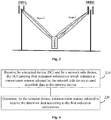
- Fig. 1 is a schematic flowchart of a method for transmitting DCI according to an embodiment of the present disclosure.
- the method shown in Fig. 1 includes the following operations in blocks 110 to 120.
- a network side device determines a transmission manner adopted to send downlink data to a terminal device.
- the network side device may determine the transmission manner to be adopted according to strength of a signal of a cell where the terminal device is located and reliability of a channel between the network side device and the terminal device. For example, when the channel is relatively reliable and the signal is relatively strong, the network side device may determine that the transmission manner for transmitting the downlink data is open-loop space division multiplexing or closed-loop space division multiplexing. When the channel is not so reliable or the signal is relatively weak, the network side device may determine that the transmission manner for transmitting the downlink data is transmission diversity. That is, the network side device may flexibly determine the transmission manner for transmitting the downlink data according to the reliability of the channel, the strength of the signal or other information.
- the transmission manner may include at least one of: open-loop space division multiplexing, closed-loop space division multiplexing, transmission diversity, open-loop MIMO, closed-loop MIMO and quasi-open-loop MIMO.
- the network side device sends DCI to the terminal device, the DCI carrying first indication information which indicates the transmission manner adopted by the network side device to send the downlink data to the terminal device.
- the manner of directly indicating the transmission manner of the downlink data through the first indication information carried in the DCI in the embodiment of the present disclosure is more flexible and higher in reliability.
- the DCI includes a first field and a value of one or more bits in the first field is the first indication information. Different values of the one or more bits in the first field correspond to different transmission manners.
- the first field may be a field newly added in the DCI to represent the first indication information.
- the first field when the first field occupies two bits, the first field has four different values and may represent at most four different transmission manners.
- a corresponding relationship between the values of the bits of the first field and the transmission manners may be as follows: 00 corresponds to transmission diversity, 01 corresponds to open-loop space division multiplexing, 10 corresponds to closed-loop space division multiplexing and 11 corresponds to reservation; alternatively, 00 corresponds to transmission diversity, 01 corresponds to open-loop MIMO, 10 corresponds to quasi-open-loop MIMO and 11 corresponds to closed-loop MIMO.
- the first field occupies more than two bits, more transmission manners may be represented. There are no limits made to the number of bits occupied by the first field in the embodiments of the present disclosure. In addition, there are no specific limits made to correspondences between different values of the bits in the first field and the transmission manners.
- the number of bits occupied by the first field may be determined according to the number of transmission manners supported by the network side device and the terminal device. For example, when three transmission manners are supported by the network side device and the terminal device, the number of bits occupied by the first field may be 2, and when five transmission manners are supported by the network side device and the terminal device, the number of bits occupied by the first field may be 3.
- the bits (there may be one or more bits) in the first field are dedicatedly adopted to indicate the first indication information, so that indication reliability of the transmission manner may be improved.
- the DCI includes a second field
- the first indication information is a value of one or more bits in the second field and different values of the one or more bits in the second field indicate different transmission manners and part of control information in the DCI.
- different values of the one or more bits in the second field may further represent other control information carried in the DCI. That is, when the second field is generated, the transmission manner and the other control information may be coded together.
- the value of the bits of the second field may not only indicate the transmission manner but also indicate the number of pilot signal ports. If the second field occupies three bits, a corresponding relationship between the value of the bits of the second field and the number of the pilot signal ports and the transmission manner may be as follows: 001 represents that there are two pilot signal ports and the transmission manner is transmission diversity; 010 represents that there are two pilot signal ports and the transmission manner is open-loop space division multiplexing; and 100 represents that there are four pilot signal ports and the transmission manner is closed-loop space division multiplexing. Similarly, there are no limits made to the number of bits occupied by the second field and there are no specific limits made to correspondences between different values of the bits in the second field and the transmission manners in the embodiment of the present disclosure.
- the DCI includes a feature code
- the first indication information is the feature code
- different values of the feature code indicate different transmission manners
- the feature code is born in a field occupied by an error-detecting code of the DCI in a manner of scrambling the error-detecting code based on the feature code.
- the network side device determines to transmit the downlink data by adopting transmission diversity
- the feature code corresponding to transmission diversity may be scrambled into the field occupied by the error-detecting code in the DCI to form a scrambled error-detecting code.
- the terminal device may execute a series of operations sequentially according to the feature codes corresponding to the four transmission manners and the received scrambled feature code to parse the error-detecting code in the DCI, and the terminal device can finally obtain the error-detecting code in the DCI by adopting the feature code corresponding to transmission diversity and successfully decode the control information in the DCI.
- the terminal device can determine that the transmission manner adopted by the network side device to transmit the downlink data is transmission diversity.
- the number of bits of the feature code may be fewer than or equal to the number of bits of the error-detecting code in the DCI.
- the feature code may occupy 12 bits and the error-detecting code in the DCI may occupy 16 bits, or the feature code and the error-detecting code both occupy 16 bits.
- the DCI sent to the terminal device by the network side device in different transmission manners has a same length.
- the network side device may equalize corresponding lengths of the DCI in different transmission modes (which may specifically be implemented in a manner of adding a number of zeros to the end of the DCI).
- the terminal device needs to detect the DCI based on the three DCI lengths on the resource where the DCI may be received, which makes it necessary to perform blind detection for many times. Therefore, compared with the related technology, the solution in this embodiment of the present disclosure has the advantage that the number of times of blind detection may be reduced.
- the length of the DCI may be preset or predetermined by the terminal device and the network side device; alternatively, the network side device, before sending the DCI to the terminal device, may send indication information to the terminal device to indicate the length of the DCI. In this way, the terminal device knows the length of the DCI when detecting the DCI.
- an LTE system of a related technology it is inconvenient to flexibly switch transmission manners between the network side device and the terminal device, and the number of the pilot signal ports and a pilot signal transmission mode are also set on the basis of a cell.
- a pilot signal configuration is expected to be made on the basis of a terminal rather than a cell, which obviously cannot be met in the LTE system of the related technology. Therefore, some pilot signal related information is born in the DCI to enhance pilot signal transmission flexibility in the method for transmitting DCI in the embodiment of the present disclosure.
- the DCI may further carry at least one of: pilot signal configuration information, first associated information and second associated information.
- the first associated information indicates whether a channel estimated by one pilot signal port is able to be deduced according to a channel estimated by another pilot signal port or not.
- the second associated information indicates whether a channel estimated by a pilot signal port is able to be deduced according to a channel estimated by another signal or not.
- the other signal is at least one of a broadcast signal, a synchronization signal and a control signal sent to the terminal device by the network side device.
- the first associated information may indicate whether a channel estimated by the second pilot signal port is able to be deduced according to a channel estimated by the first pilot signal port or not.
- the first associated information may occupy 1 bit, when the value of the bit is 0, it is indicated that the channel estimated by the second pilot signal port is not able to be deduced according to the channel estimated by the first pilot signal port; and when the value of the bit is 1, it is indicated that the channel estimated by the second pilot signal port is able to be deduced according to the channel estimated by the first pilot signal port. Then, the terminal device may determine whether to deduce the channel estimated by the second pilot signal port according to the channel estimated by the first pilot signal port or not according to the first associated information.
- the network side device may also determine whether the channel estimated by the pilot signal port is able to be deduced according to the channel estimated by the other signal or not and transmit the corresponding channel to the terminal device through the second associated information. For example, the network side device determines that the channel estimated by the first pilot signal port is able to be deduced according to a channel estimated by the synchronization signal, then generates the second associated information and sends the second associated information to the terminal device. The terminal device, after receiving the second associated information, may deduce the channel estimated by the first pilot signal port according to the channel estimated by the synchronization signal.
- the other signal may alternatively be a signal except the broadcast signal, the synchronization signal and the control signal sent to the terminal device by the network side device.
- the pilot signal port may be understood as a pilot signal transmission port.
- the network side device may determine the first associated information according to a relationship between pilot signal ports.
- the network side device may determine the first associated information according to a position relationship or polarization direction relationship between the pilot signal ports. For example, the network side device sends a pilot signal to the terminal device through the first pilot signal port and the second pilot signal port. If a distance between the first pilot signal port and the second pilot signal port is relatively short or polarization directions are relatively similar, the network side device may determine that the first associated information indicates that the channel estimated by the second pilot signal port is able to be deduced according to the channel estimated by the first pilot signal port.
- the network side device may determine that the first associated information indicates that the channel estimated by the second pilot signal port is not able to be deduced according to the channel estimated by the first pilot signal port.
- pilot signal transmission ports transmitting pilot signals and part of pilot signal ports in these pilot signal ports may correspond to the same Transmit and Receive Point (TRP).
- TRP Transmit and Receive Point
- the pilot signal ports may alternatively correspond to different TRPs.
- the pilot signal ports may correspond to the same beam or different beams under the same TRP.
- the pilot signal configuration information may include at least one of: a number of pilot signal ports, a pilot signal position, a pilot signal density and pilot signal scrambling information.
- the pilot signal configuration information may be represented by adopting a field, which is dedicated to indicating the pilot signal configuration information, in the DCI. For example, if demodulation reference signals of at most eight ports are expected to be supported, at most three bits may be adopted to represent the number of the pilot ports. In addition, when the pilot signal position and density are represented, a few bits (for example, two bits) may be adopted to represent different pilot signal transmission positions and different pilot signal densities.
- the network side device may send a pilot configuration pool to the terminal device in advance through high-layer signaling. Then, the network side device adopts a number of bits to indicate a pilot configuration in the DCI according to a practical condition.
- the information indicating the pilot configuration may be independently coded, or may be jointly coded, or may be coded together with other control information.
- the pilot signal position may refer to a position of a time-frequency resource on which the pilot signal is sent.
- the DCI further carries second indication information which indicates whether the terminal device receives the downlink data in a multi-user MIMO mode or not.
- the network side device may configure different MIMO transmission manners for the terminal device.
- the network side device may configure MIMO with two transmission antennae for the terminal device.
- the network side device may configure MIMO with four transmission antennae for the terminal device, two antennae are from the cell, the other two antennae are from the adjacent cell and all of the four antennae may provide space division multiplexing or transmission diversity manner-based data transmission for the terminal device.
- the network side device may configure MIMO with two transmission antennae for the terminal device, that is, the MIMO transmission manner may be switched from MIMO with four antennae to MIMO with two antennae.
- the method for transmitting DCI of the embodiments of the present disclosure is described above from the perspective of the network side device in combination with Fig. 1 to Fig. 3 in detail.
- the method for transmitting DCI of the embodiments of the present disclosure will be described below from the perspective of the terminal device in combination with Fig. 4 .
- a process of the method for transmitting DCI shown in Fig. 4 corresponds to the process of the method for transmitting DCI of the embodiments of the present disclosure in Fig. 1 .
- Explanations and definitions made above to the method for transmitting DCI of the embodiments of the present disclosure are also applicable to the method for transmitting DCI shown in Fig. 4 . For simplicity, repeated descriptions are eliminated herein.
- Fig. 4 is a schematic flowchart of a method for transmitting DCI according to an embodiment of the present disclosure.
- the method shown in Fig. 4 includes the following operations in blocks 210 to 220.
- a terminal device receives DCI sent by a network side device, the DCI carrying first indication information which indicates a transmission manner adopted by the network side device to send downlink data to the terminal device.
- the terminal device determines a transmission manner adopted to receive the downlink data according to the first indication information.
- the manner of directly indicating the transmission manner of the downlink data through the first indication information carried in the DCI in the embodiment of the present disclosure is more flexible and higher in reliability.
- the transmission mode includes at least one of: open-loop space division multiplexing, closed-loop space division multiplexing, transmission diversity, open-loop MIMO, closed-loop MIMO and quasi-open-loop MIMO.
- the first indication information may indicate multiple transmission manners to facilitate the network side device and the terminal to switch between different transmission modes.
- the DCI includes a first field
- the first indication information is a value of one or more bits in the first field
- different values of the one or more bits in the first field indicate different transmission manners.
- the first field may be a field dedicatedly adopted for indicating the transmission manner, so that different transmission manners may be indicated more directly and more accurately.
- the DCI includes a second field
- the first indication information is a value of one or more bits in the second field and different values of the one or more bits in the second field indicate different transmission manners and part of control information in the DCI.
- the transmission manner and part of control information in the DCI are indicated through the second field, so that the number of fields or bits occupied for indicating different transmission manners may be reduced.
- the DCI includes a feature code
- the first indication information is the feature code
- different values of the feature code indicate different transmission manners
- the feature code is born in a field occupied by an error-detecting code of the DCI in a manner of scrambling the error-detecting code based on the feature code.
- the DCI further carries at least one of: pilot signal configuration information, first associated information and second associated information.
- the first associated information indicates whether a channel estimated by one pilot signal port is able to be deduced according to a channel estimated by another pilot signal port or not.
- the second associated information indicates whether a channel estimated by a pilot signal port is able to be deduced according to a channel estimated by another signal or not, the other signal being at least one of: a broadcast signal, a synchronization signal and a control signal sent to the terminal device by the network side device.
- the pilot signal configuration information includes at least one of: a number of pilot signal ports, a pilot signal position, a pilot signal density and a pilot signal scrambling information.
- the DCI further carries second indication information which indicates whether the terminal device receives the downlink data in a multi-user MIMO mode or not.
- the method for transmitting DCI of the embodiments of the present disclosure is described above in combination with Fig. 1 to Fig. 4 in detail.
- a network side device and terminal device of the embodiments of the present disclosure will be described below in combination with Fig. 5 to Fig. 8 in detail. It is to be understood that the network side device and terminal device in Fig. 5 to Fig. 8 may execute each operation executed by the network side device and terminal device above and, for avoiding repetitions, will not be elaborated herein.
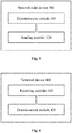
- Fig. 5 is a schematic block diagram of a network side device according to an embodiment of the present disclosure.
- the network side device 300 shown in Fig. 5 includes:
- the manner of directly indicating the transmission manner of the downlink data through the first indication information carried in the DCI in the embodiment of the present disclosure is more flexible and higher in reliability.
- the transmission mode includes at least one of: open-loop space division multiplexing, closed-loop space division multiplexing, transmission diversity, open-loop MIMO, closed-loop MIMO and quasi-open-loop MIMO.
- the DCI includes a first field
- the first indication information is a value of one or more bits in the first field
- different values of the one or more bits in the first field indicate different transmission manners.
- the DCI includes a second field
- the first indication information is a value of one or more bits in the second field and different values of the one or more bits in the second field indicate different transmission manners and part of control information in the DCI.
- the DCI includes a feature code
- the first indication information is the feature code
- different values of the feature code indicate different transmission manners
- the feature code is born in a field occupied by an error-detecting code of the DCI in a manner of scrambling the error-detecting code based on the feature code.
- the DCI further carries at least one of: pilot signal configuration information, first associated information and second associated information.
- the first associated information indicates whether a channel estimated by one pilot signal port is able to be deduced according to a channel estimated by another pilot signal port or not.
- the second associated information indicates whether a channel estimated by a pilot signal port is able to be deduced according to a channel estimated by another signal or not, the other signal being at least one of: a broadcast signal, a synchronization signal and a control signal sent to the terminal device by the network side device.
- the pilot signal configuration information includes at least one of: a number of pilot signal ports, a pilot signal position, a pilot signal density and a pilot signal scrambling information.
- the DCI further carries second indication information which indicates whether the terminal device receives the downlink data in a multi-user MIMO mode or not.
- the DCI sent to the terminal device by the network side device in different transmission manners has a same length.
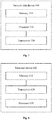
- Fig. 6 is a schematic block diagram of a terminal device according to an embodiment of the present disclosure.
- the terminal device 400 shown in Fig. 6 includes:
- the manner of directly indicating the transmission manner of the downlink data through the first indication information carried in the DCI in the embodiment of the present disclosure is more flexible and higher in reliability.
- the transmission mode includes at least one of: open-loop space division multiplexing, closed-loop space division multiplexing, transmission diversity, open-loop MIMO, closed-loop MIMO and quasi-open-loop MIMO.
- the DCI includes a first field
- the first indication information is a value of one or more bits in the first field
- different values of the one or more bits in the first field indicate different transmission manners.
- the DCI includes a second field
- the first indication information is a value of one or more bits in the second field and different values of the one or more bits in the second field indicate different transmission manners and part of control information in the DCI.
- the DCI includes a feature code
- the first indication information is the feature code
- different values of the feature code indicate different transmission manners
- the feature code is born in a field occupied by an error-detecting code of the DCI in a manner of scrambling the error-detecting code based on the feature code.
- the DCI further carries at least one of: pilot signal configuration information, first associated information and second associated information.
- the first associated information indicates whether a channel estimated by one pilot signal port is able to be deduced according to a channel estimated by another pilot signal port or not.
- the second associated information indicates whether a channel estimated by a pilot signal port is able to be deduced according to a channel estimated by another signal or not, the other signal being at least one of: a broadcast signal, a synchronization signal and a control signal sent to the terminal device by the network side device.
- the pilot signal configuration information includes at least one of: a number of pilot signal ports, a pilot signal position, a pilot signal density and a pilot signal scrambling information.
- the DCI further carries second indication information which indicates whether the terminal device receives the downlink data in a multi-user MIMO mode or not.
- Fig. 7 is a schematic block diagram of a network side device according to an embodiment of the present disclosure.
- the network side device 500 shown in Fig. 7 includes:
- the manner of directly indicating the transmission manner of the downlink data through the first indication information carried in the DCI in the embodiment of the present disclosure is more flexible and higher in reliability.
- the transmission mode includes at least one of: open-loop space division multiplexing, closed-loop space division multiplexing, transmission diversity, open-loop MIMO, closed-loop MIMO and quasi-open-loop MIMO.
- the DCI includes a first field
- the first indication information is a value of one or more bits in the first field
- different values of the one or more bits in the first field indicate different transmission manners.
- the DCI includes a second field
- the first indication information is a value of one or more bits in the second field and different values of the one or more bits in the second field indicate different transmission manners and part of control information in the DCI.
- the DCI includes a feature code
- the first indication information is the feature code
- different values of the feature code indicate different transmission manners
- the feature code is born in a field occupied by an error-detecting code of the DCI in a manner of scrambling the error-detecting code based on the feature code.
- the DCI further carries at least one of: pilot signal configuration information, first associated information and second associated information.
- the first associated information indicates whether a channel estimated by one pilot signal port is able to be deduced according to a channel estimated by another pilot signal port or not.
- the second associated information indicates whether a channel estimated by a pilot signal port is able to be deduced according to a channel estimated by another signal or not, the other signal being at least one of: a broadcast signal, a synchronization signal and a control signal sent to the terminal device by the network side device.
- the pilot signal configuration information includes at least one of: a number of pilot signal ports, a pilot signal position, a pilot signal density and a pilot signal scrambling information.
- the DCI further carries second indication information which indicates whether the terminal device receives the downlink data in a multi-user MIMO mode or not.
- the DCI sent to the terminal device by the network side device in different transmission manners has a same length.
- Fig. 8 is a schematic block diagram of a terminal device according to an embodiment of the present disclosure.
- the terminal device 600 shown in Fig. 8 includes:
- the manner of directly indicating the transmission manner of the downlink data through the first indication information carried in the DCI in the embodiment of the present disclosure is more flexible and higher in reliability.
- the transmission mode includes at least one of: open-loop space division multiplexing, closed-loop space division multiplexing, transmission diversity, open-loop MIMO, closed-loop MIMO and quasi-open-loop MIMO.
- the DCI includes a first field
- the first indication information is a value of one or more bits in the first field
- different values of the one or more bits in the first field indicate different transmission manners.
- the DCI includes a second field
- the first indication information is a value of one or more bits in the second field and different values of the one or more bits in the second field indicate different transmission manners and part of control information in the DCI.
- the DCI includes a feature code
- the first indication information is the feature code
- different values of the feature code indicate different transmission manners
- the feature code is born in a field occupied by an error-detecting code of the DCI in a manner of scrambling the error-detecting code based on the feature code.
- the DCI further carries at least one of: pilot signal configuration information, first associated information and second associated information.
- the first associated information indicates whether a channel estimated by one pilot signal port is able to be deduced according to a channel estimated by another pilot signal port or not.
- the second associated information indicates whether a channel estimated by a pilot signal port is able to be deduced according to a channel estimated by another signal or not, the other signal being at least one of: a broadcast signal, a synchronization signal and a control signal sent to the terminal device by the network side device.
- the pilot signal configuration information includes at least one of: a number of pilot signal ports, a pilot signal position, a pilot signal density and a pilot signal scrambling information.
- the DCI further carries second indication information which indicates whether the terminal device receives the downlink data in a multi-user MIMO mode or not.
- the disclosed systems, devices and methods may be implemented in another manner.
- the device embodiment described above is only schematic, and for example, division of the units is only based on logic functions, and other division manners may be adopted during practical implementation.
- multiple units or components may be combined or integrated into another system, or some characteristics may be neglected or not executed.
- coupling or direct coupling or communication connection between each displayed or discussed component may be indirect coupling or communication connection of the device or the units implemented through some interfaces, and may be electrical, mechanical or in other forms.
- the units described as separate parts may or may not be physically separated. Parts displayed as units may or may not be physical units, and may be located in the same place or may alternatively be distributed to multiple network units. Part or all of the units may be selected to achieve the purpose of the solutions of the embodiments according to a practical requirement.
- each function unit in each embodiment of the present disclosure may be integrated into a processing unit or may exist independently, and alternatively, two or more than two units may be integrated into one unit.
- the function When being realized in the form of software functional unit and sold or used as an independent product, the function may be stored in a computer-readable storage medium.
- a part of the technical solutions or the part of the technical solutions of the embodiments of the present disclosure substantially making contributions to the related technology may be embodied in a form of software product.
- the software product may be stored in a storage medium, including a plurality of instructions configured to enable a computer device (which may be a personal computer, a server, a network device or the like) to execute all or part of the operations of the method in each embodiment of the present disclosure.
- the abovementioned storage medium includes: various media capable of storing program codes such as a U disk, a mobile hard disk, a Read-Only Memory (ROM), a Random Access Memory (RAM), a magnetic disk or an optical disk.
Landscapes
- Engineering & Computer Science (AREA)
- Signal Processing (AREA)
- Computer Networks & Wireless Communication (AREA)
- Quality & Reliability (AREA)
- Mobile Radio Communication Systems (AREA)
- Radio Transmission System (AREA)
Abstract
Description
- The present disclosure relates to the field of mobile communication, and more particularly to a method and device for transmitting Downlink Control Information (DCI).
- For adaptation to requirements of different application scenarios, different transmission modes are defined for Long Term Evolution (LTE) systems and different transmission manners are further defined in each transmission mode. In a certain transmission mode, a base station may adopt a main transmission manner which is supported in the transmission mode to send downlink data to a terminal device and, when a channel is unreliable or signal strength is relatively low, the base station may switch to another transmission manner to send the downlink data to the terminal device, that is, the base station may dynamically switch between different transmission manners in the transmission mode. Generally speaking, DCI corresponding to different transmission manners are different in length. Therefore, the terminal device may perform blind detection on DCI sent by the base station according to the lengths of the DCI corresponding to different transmission manners to further determine the transmission manner adopted by the base station.
- In an LTE system, switching between different transmission modes requires interaction of high-layer signaling and a required switching time is relatively long. In addition, in each mode, a terminal device indirectly determines a transmission manner according to a length of detected DCI, and such a manner may not be so accurate and flexible.
- Embodiments of the present disclosure provides a method for transmitting DCI, a network side device and a terminal device, which may improve the flexibility and reliability of indicating a transmission manner of downlink data by the network side device.
- A first exemplary embodiment provides a method for transmitting DCI, which may include that: a network side device determines a transmission manner adopted to send downlink data to a terminal device; and the network side device sends DCI to the terminal device, the DCI carrying first indication information which indicates the transmission manner adopted by the network side device to send the downlink data to the terminal device.
- Compared with a manner of indirectly indicating a transmission manner of downlink data through a length of the DCI adopted in a related technology, the manner of directly indicating the transmission manner of the downlink data through the first indication information carried in the DCI is more flexible and higher in reliability.
- In some implementations of the first exemplary embodiment, the transmission mode may include at least one of: open-loop space division multiplexing, closed-loop space division multiplexing, transmission diversity, open-loop Multiple Input Multiple Output (MIMO), closed-loop MIMO and quasi-open-loop MIMO.
- The first indication information may indicate multiple transmission manners to facilitate the network side device and the terminal to switch between different transmission modes.
- In some implementations of the first exemplary embodiment, the DCI may include a first field, the first indication information may be a value of one or more bits in the first field, and different values of the one or more bits in the first field may indicate different transmission manners.
- The first field may be a field dedicatedly adopted for indicating the transmission manner, so that different transmission manners may be indicated more directly and more accurately.
- In some implementations of the first exemplary embodiment, the DCI may include a second field, the first indication information may be a value of one or more bits in the second field and different values of the one or more bits in the second field may indicate different transmission manners and part of control information in the DCI.
- The transmission manner and part of control information in the DCI are indicated through the second field, so that the number of fields or bits occupied for indicating different transmission manners may be reduced.
- In some implementations of the first exemplary embodiment, the DCI may include a feature code, the first indication information may be the feature code, different values of the feature code may indicate different transmission manners and the feature code may be carried in a field occupied by an error-detecting code of the DCI in a manner of scrambling the error-detecting code based on the feature code.
- In some implementations of the first exemplary embodiment, the DCI may further carry at least one of: pilot signal configuration information, first associated information and second associated information. The first associated information may indicate whether a channel estimated by one pilot signal port is able to be deduced according to a channel estimated by another pilot signal port or not. The second associated information may indicate whether a channel estimated by a pilot signal port is able to be deduced according to a channel estimated by another signal or not. In some implementations, the other signal mentioned herein may be at least one of: a broadcast signal, a synchronization signal and a control signal sent to the terminal device by the network side device.
- In some implementations of the first exemplary embodiment, the pilot signal configuration information may include at least one of: a number of pilot signal ports, a pilot signal position, a pilot signal density and a pilot signal scrambling information.
- In some implementations of the first exemplary embodiment, the DCI may further carry second indication information which may indicate whether the terminal device receives the downlink data in a multi-user MIMO mode or not.
- In some implementations of the first exemplary embodiment, the DCI sent to the terminal device by the network side device in different transmission manners may have a same length.
- A second exemplary embodiment provides a method for transmitting DCI, which may include that: a terminal device receives DCI sent by a network side device, the DCI carrying first indication information which indicates a transmission manner adopted by the network side device to send downlink data to the terminal device; and the terminal device determines a transmission manner adopted to receive the downlink data according to the first indication information.
- Compared with a manner of indirectly indicating a transmission manner of downlink data through a length of the DCI adopted in the related technology, the manner of directly indicating the transmission manner of the downlink data through the first indication information carried in the DCI is more flexible and higher in reliability.
- In some implementations of the second exemplary embodiment, the transmission mode may include at least one of: open-loop space division multiplexing, closed-loop space division multiplexing, transmission diversity, open-loop MIMO, closed-loop MIMO and quasi-open-loop MIMO.
- In some implementations of the second exemplary embodiment, the DCI may include a first field, the first indication information may be a value of one or more bits in the first field, and different values of the one or more bits in the first field may indicate different transmission manners.
- In some implementations of the second exemplary embodiment, the DCI may include a second field, the first indication information may be a value of one or more bits in the second field and different values of the one or more bits in the second field may indicate different transmission manners and part of control information in the DCI.
- In some implementations of the second exemplary embodiment, the DCI may include a feature code, the first indication information may be the feature code, different values of the feature code may indicate different transmission manners and the feature code may be carried in a field occupied by an error-detecting code of the DCI in a manner of scrambling the error-detecting code based on the feature code.
- In some implementations of the second exemplary embodiment, the DCI may further carry at least one of: pilot signal configuration information, first associated information and second associated information. The first associated information may indicate whether a channel estimated by one pilot signal port is able to be deduced according to a channel estimated by another pilot signal port or not. The second associated information may indicate whether a channel estimated by a pilot signal port is able to be deduced according to a channel estimated by another signal or not. In some implementations, the other signal mentioned herein may be at least one of: a broadcast signal, a synchronization signal and a control signal sent to the terminal device by the network side device.
- In some implementations of the second exemplary embodiment, the pilot signal configuration information may include at least one of: a number of pilot signal ports, a pilot signal position, a pilot signal density and a pilot signal scrambling information.
- In some implementations of the second exemplary embodiment, the DCI may further carry second indication information which may indicate whether the terminal device receives the downlink data in a multi-user MIMO mode or not.
- In some implementations, different values of the one or more bits in the second field indicate different transmission manners and pilot signal configuration information.
- In some implementations, different values of the one or more bits in the second field indicate different transmission manners and different numbers of pilot signal ports.
- In some implementations, before the operation that the network side device sends the DCI to the terminal device, the method may further include that: the network side device sends third indication information to the terminal device. In the implementations, the third indication information is used for indicating a length of the DCI sent to the terminal device by the network side device.
- A third exemplary embodiment provides a network side device, which includes modules configured to execute the method in the first exemplary embodiment.
- A fourth exemplary embodiment provides a terminal device, which includes modules configured to execute the method in the second exemplary embodiment.
- A fifth exemplary embodiment provides a network side device, which includes a memory, a processor and a transceiver. The memory is configured to store a program. The processor is configured to execute the program. When the program is executed, the processor and the transceiver are configured to execute the method in the first exemplary embodiment.
- A sixth exemplary embodiment provides a terminal device, which includes a memory, a processor and a transceiver. The memory is configured to store a program. The processor is configured to execute the program. When the program is executed, the processor and the transceiver are configured to execute the method in the second exemplary embodiment.
- A seventh exemplary embodiment provides a computer-readable medium, which stores a program code to be executed by a device, the program code including an instruction configured to execute the method in the first exemplary embodiment.
- An eighth exemplary embodiment provides a computer-readable medium, which stores a program code to be executed by a device, the program code including an instruction configured to execute the method in the second exemplary embodiment.
-
-
Fig. 1 is a schematic flowchart of a method for transmitting DCI according to an embodiment of the present disclosure; -
Fig. 2 is a schematic diagram of MIMO with two transmission antennae; -
Fig. 3 is a schematic diagram of MIMO with four transmission antennae; -
Fig. 4 is a schematic flowchart of a method for transmitting DCI according to an embodiment of the present disclosure; -
Fig. 5 is a schematic block diagram of a network side device according to an embodiment of the present disclosure; -
Fig. 6 is a schematic block diagram of a terminal device according to an embodiment of the present disclosure; -
Fig. 7 is a schematic block diagram of a network side device according to an embodiment of the present disclosure; and -
Fig. 8 is a schematic block diagram of a terminal device according to an embodiment of the present disclosure. - It is to be understood that the technical solutions of the embodiments of the present disclosure may be applied to various communication systems, for example, a present communication system of a Global System of Mobile Communication (GSM), a Code Division Multiple Access (CDMA) system, a Wideband Code Division Multiple Access (WCDMA) system, a General Packet Radio Service (GPRS), an LTE system, a Universal Mobile Telecommunication System (UMTS) and the like, and may particularly be applied to a future 5th-Generation (5G) system.
- In the embodiments of the present disclosure, a terminal device may refer to User Equipment (UE), an access terminal, a user unit, a user station, a mobile station, a mobile radio station, a remote station, a remote terminal, a mobile device, a user terminal, a terminal, a wireless communication device, a user agent or a user device. The access terminal may be a cell phone, a cordless phone, a Session Initiation Protocol (SIP) phone, a Wireless Local Loop (WLL) station, a Personal Digital Assistant (PDA), a handheld device with a wireless communication function, a computing device, another processing device connected to a wireless modem, a vehicle-mounted device, a wearable device, a terminal device in a future 5G network, a terminal device in a future evolved Public Land Mobile Network (PLMN) or the like. There are no limits made in the embodiments of the present disclosure.
- In the embodiments of the present disclosure, a network side device may be a device configured to communicate with the terminal device. The network side device may be a Base Transceiver Station (BTS) in the GSM or the CDMA, or a NodeB (NB) in the WCDMA system, or an Evolutional Node B (eNB or eNodeB) in the LTE system, or a wireless controller in a Cloud Radio Access Network (CRAN) scenario. Alternatively, the network device may be a relay station, an access point, a vehicle-mounted device, a wearable device or a network side device in the future 5G network, a network side device in the future evolved PLMN or the like. There are no limits made in the embodiments of the present disclosure.
-
Fig. 1 is a schematic flowchart of a method for transmitting DCI according to an embodiment of the present disclosure. The method shown inFig. 1 includes the following operations inblocks 110 to 120. - In
block 110, a network side device determines a transmission manner adopted to send downlink data to a terminal device. - The network side device may determine the transmission manner to be adopted according to strength of a signal of a cell where the terminal device is located and reliability of a channel between the network side device and the terminal device. For example, when the channel is relatively reliable and the signal is relatively strong, the network side device may determine that the transmission manner for transmitting the downlink data is open-loop space division multiplexing or closed-loop space division multiplexing. When the channel is not so reliable or the signal is relatively weak, the network side device may determine that the transmission manner for transmitting the downlink data is transmission diversity. That is, the network side device may flexibly determine the transmission manner for transmitting the downlink data according to the reliability of the channel, the strength of the signal or other information.
- In at least one exemplary embodiment, the transmission manner may include at least one of: open-loop space division multiplexing, closed-loop space division multiplexing, transmission diversity, open-loop MIMO, closed-loop MIMO and quasi-open-loop MIMO.
- In
block 120, the network side device sends DCI to the terminal device, the DCI carrying first indication information which indicates the transmission manner adopted by the network side device to send the downlink data to the terminal device. - Compared with a manner of indirectly indicating a transmission manner of downlink data through a length of the DCI adopted in a related technology, the manner of directly indicating the transmission manner of the downlink data through the first indication information carried in the DCI in the embodiment of the present disclosure is more flexible and higher in reliability.
- In at least one exemplary embodiment, the DCI includes a first field and a value of one or more bits in the first field is the first indication information. Different values of the one or more bits in the first field correspond to different transmission manners. The first field may be a field newly added in the DCI to represent the first indication information.
- For example, when the first field occupies two bits, the first field has four different values and may represent at most four different transmission manners. As an example, a corresponding relationship between the values of the bits of the first field and the transmission manners may be as follows: 00 corresponds to transmission diversity, 01 corresponds to open-loop space division multiplexing, 10 corresponds to closed-loop space division multiplexing and 11 corresponds to reservation; alternatively, 00 corresponds to transmission diversity, 01 corresponds to open-loop MIMO, 10 corresponds to quasi-open-loop MIMO and 11 corresponds to closed-loop MIMO. When the first field occupies more than two bits, more transmission manners may be represented. There are no limits made to the number of bits occupied by the first field in the embodiments of the present disclosure. In addition, there are no specific limits made to correspondences between different values of the bits in the first field and the transmission manners.
- The number of bits occupied by the first field may be determined according to the number of transmission manners supported by the network side device and the terminal device. For example, when three transmission manners are supported by the network side device and the terminal device, the number of bits occupied by the first field may be 2, and when five transmission manners are supported by the network side device and the terminal device, the number of bits occupied by the first field may be 3.
- The bits (there may be one or more bits) in the first field are dedicatedly adopted to indicate the first indication information, so that indication reliability of the transmission manner may be improved.
- In at least one exemplary embodiment, the DCI includes a second field, the first indication information is a value of one or more bits in the second field and different values of the one or more bits in the second field indicate different transmission manners and part of control information in the DCI.
- It is to be understood that different values of the one or more bits in the second field may further represent other control information carried in the DCI. That is, when the second field is generated, the transmission manner and the other control information may be coded together. For example, the value of the bits of the second field may not only indicate the transmission manner but also indicate the number of pilot signal ports. If the second field occupies three bits, a corresponding relationship between the value of the bits of the second field and the number of the pilot signal ports and the transmission manner may be as follows: 001 represents that there are two pilot signal ports and the transmission manner is transmission diversity; 010 represents that there are two pilot signal ports and the transmission manner is open-loop space division multiplexing; and 100 represents that there are four pilot signal ports and the transmission manner is closed-loop space division multiplexing. Similarly, there are no limits made to the number of bits occupied by the second field and there are no specific limits made to correspondences between different values of the bits in the second field and the transmission manners in the embodiment of the present disclosure.
- In at least one exemplary embodiment, the DCI includes a feature code, the first indication information is the feature code, different values of the feature code indicate different transmission manners, and the feature code is born in a field occupied by an error-detecting code of the DCI in a manner of scrambling the error-detecting code based on the feature code.
- For example, assuming that there are four transmission manners in total and each transmission manner corresponds to one feature code. When the network side device determines to transmit the downlink data by adopting transmission diversity, the feature code corresponding to transmission diversity may be scrambled into the field occupied by the error-detecting code in the DCI to form a scrambled error-detecting code. After receiving the DCI, the terminal device may execute a series of operations sequentially according to the feature codes corresponding to the four transmission manners and the received scrambled feature code to parse the error-detecting code in the DCI, and the terminal device can finally obtain the error-detecting code in the DCI by adopting the feature code corresponding to transmission diversity and successfully decode the control information in the DCI. In such case, the terminal device can determine that the transmission manner adopted by the network side device to transmit the downlink data is transmission diversity.
- The number of bits of the feature code may be fewer than or equal to the number of bits of the error-detecting code in the DCI. For example, the feature code may occupy 12 bits and the error-detecting code in the DCI may occupy 16 bits, or the feature code and the error-detecting code both occupy 16 bits.
- In at least one exemplary embodiment, the DCI sent to the terminal device by the network side device in different transmission manners has a same length. The network side device may equalize corresponding lengths of the DCI in different transmission modes (which may specifically be implemented in a manner of adding a number of zeros to the end of the DCI). By adopting this solution, unlike a related technology in which the terminal device performs blind detection on the DCI based on different DCI lengths on a resource where the DCI may be received respectively, the terminal device only needs to directly detect the DCI according to the same DCI length at a resource position where the DCI of the terminal device may be received. For example, if there are three possible transmission manners, and DCI lengths corresponding to the three transmission manners are 30bit, 40bit and 50bit respectively, according to the related technology, the terminal device needs to detect the DCI based on the three DCI lengths on the resource where the DCI may be received, which makes it necessary to perform blind detection for many times. Therefore, compared with the related technology, the solution in this embodiment of the present disclosure has the advantage that the number of times of blind detection may be reduced.
- It is to be understood that the length of the DCI may be preset or predetermined by the terminal device and the network side device; alternatively, the network side device, before sending the DCI to the terminal device, may send indication information to the terminal device to indicate the length of the DCI. In this way, the terminal device knows the length of the DCI when detecting the DCI.
- In an LTE system of a related technology, it is inconvenient to flexibly switch transmission manners between the network side device and the terminal device, and the number of the pilot signal ports and a pilot signal transmission mode are also set on the basis of a cell. In a future system, for improving flexibility (for example, supporting rapid switching of the terminal device between beams and between cells), a pilot signal configuration is expected to be made on the basis of a terminal rather than a cell, which obviously cannot be met in the LTE system of the related technology. Therefore, some pilot signal related information is born in the DCI to enhance pilot signal transmission flexibility in the method for transmitting DCI in the embodiment of the present disclosure.
- In at least one exemplary embodiment, the DCI may further carry at least one of: pilot signal configuration information, first associated information and second associated information. The first associated information indicates whether a channel estimated by one pilot signal port is able to be deduced according to a channel estimated by another pilot signal port or not. The second associated information indicates whether a channel estimated by a pilot signal port is able to be deduced according to a channel estimated by another signal or not. Herein, the other signal is at least one of a broadcast signal, a synchronization signal and a control signal sent to the terminal device by the network side device.
- If there are two pilot signal ports, respectively being a first pilot signal port and a second pilot signal port, the first associated information may indicate whether a channel estimated by the second pilot signal port is able to be deduced according to a channel estimated by the first pilot signal port or not. As an exemplary implementation, the first associated information may occupy 1 bit, when the value of the bit is 0, it is indicated that the channel estimated by the second pilot signal port is not able to be deduced according to the channel estimated by the first pilot signal port; and when the value of the bit is 1, it is indicated that the channel estimated by the second pilot signal port is able to be deduced according to the channel estimated by the first pilot signal port. Then, the terminal device may determine whether to deduce the channel estimated by the second pilot signal port according to the channel estimated by the first pilot signal port or not according to the first associated information.
- Similarly, the network side device may also determine whether the channel estimated by the pilot signal port is able to be deduced according to the channel estimated by the other signal or not and transmit the corresponding channel to the terminal device through the second associated information. For example, the network side device determines that the channel estimated by the first pilot signal port is able to be deduced according to a channel estimated by the synchronization signal, then generates the second associated information and sends the second associated information to the terminal device. The terminal device, after receiving the second associated information, may deduce the channel estimated by the first pilot signal port according to the channel estimated by the synchronization signal. Herein, the other signal may alternatively be a signal except the broadcast signal, the synchronization signal and the control signal sent to the terminal device by the network side device.
- The pilot signal port may be understood as a pilot signal transmission port. In at least one exemplary embodiment, the network side device may determine the first associated information according to a relationship between pilot signal ports. As an exemplary implementation, the network side device may determine the first associated information according to a position relationship or polarization direction relationship between the pilot signal ports. For example, the network side device sends a pilot signal to the terminal device through the first pilot signal port and the second pilot signal port. If a distance between the first pilot signal port and the second pilot signal port is relatively short or polarization directions are relatively similar, the network side device may determine that the first associated information indicates that the channel estimated by the second pilot signal port is able to be deduced according to the channel estimated by the first pilot signal port. If the distance between the first pilot signal port and the second pilot signal port is relatively long or the polarization directions are very different, the network side device may determine that the first associated information indicates that the channel estimated by the second pilot signal port is not able to be deduced according to the channel estimated by the first pilot signal port.
- It is to be understood that, in some embodiments of the present disclosure, there may be multiple pilot signal transmission ports transmitting pilot signals and part of pilot signal ports in these pilot signal ports may correspond to the same Transmit and Receive Point (TRP). The pilot signal ports may alternatively correspond to different TRPs. When the pilot signal ports correspond to the same TRP, the pilot signal ports may correspond to the same beam or different beams under the same TRP.
- The pilot signal configuration information may include at least one of: a number of pilot signal ports, a pilot signal position, a pilot signal density and pilot signal scrambling information.
- The pilot signal configuration information may be represented by adopting a field, which is dedicated to indicating the pilot signal configuration information, in the DCI. For example, if demodulation reference signals of at most eight ports are expected to be supported, at most three bits may be adopted to represent the number of the pilot ports. In addition, when the pilot signal position and density are represented, a few bits (for example, two bits) may be adopted to represent different pilot signal transmission positions and different pilot signal densities.
- When there is much pilot signal configuration information, the network side device may send a pilot configuration pool to the terminal device in advance through high-layer signaling. Then, the network side device adopts a number of bits to indicate a pilot configuration in the DCI according to a practical condition. The information indicating the pilot configuration may be independently coded, or may be jointly coded, or may be coded together with other control information. In addition, the pilot signal position may refer to a position of a time-frequency resource on which the pilot signal is sent.
- In at least one exemplary embodiment, the DCI further carries second indication information which indicates whether the terminal device receives the downlink data in a multi-user MIMO mode or not.
- As shown in
Fig. 2 andFig. 3 , when the terminal device is at different positions in a cell, the network side device may configure different MIMO transmission manners for the terminal device. InFig. 2 , when the terminal device is under coverage of a certain beam in the cell, the network side device may configure MIMO with two transmission antennae for the terminal device. As shown inFig. 3 , when the terminal device moves to an edge of the cell and enters coverage of an adjacent cell, the network side device may configure MIMO with four transmission antennae for the terminal device, two antennae are from the cell, the other two antennae are from the adjacent cell and all of the four antennae may provide space division multiplexing or transmission diversity manner-based data transmission for the terminal device. When a signal of one cell is relatively weak, the network side device may configure MIMO with two transmission antennae for the terminal device, that is, the MIMO transmission manner may be switched from MIMO with four antennae to MIMO with two antennae. - The method for transmitting DCI of the embodiments of the present disclosure is described above from the perspective of the network side device in combination with
Fig. 1 to Fig. 3 in detail. The method for transmitting DCI of the embodiments of the present disclosure will be described below from the perspective of the terminal device in combination withFig. 4 . It is to be understood that a process of the method for transmitting DCI shown inFig. 4 corresponds to the process of the method for transmitting DCI of the embodiments of the present disclosure inFig. 1 . Explanations and definitions made above to the method for transmitting DCI of the embodiments of the present disclosure are also applicable to the method for transmitting DCI shown inFig. 4 . For simplicity, repeated descriptions are eliminated herein. -
Fig. 4 is a schematic flowchart of a method for transmitting DCI according to an embodiment of the present disclosure. The method shown inFig. 4 includes the following operations inblocks 210 to 220. - In
block 210, a terminal device receives DCI sent by a network side device, the DCI carrying first indication information which indicates a transmission manner adopted by the network side device to send downlink data to the terminal device. - In
block 220, the terminal device determines a transmission manner adopted to receive the downlink data according to the first indication information. - Compared with a manner of indirectly indicating a transmission manner of downlink data through a length of the DCI adopted in the related technology, the manner of directly indicating the transmission manner of the downlink data through the first indication information carried in the DCI in the embodiment of the present disclosure is more flexible and higher in reliability.
- In at least one exemplary embodiment, the transmission mode includes at least one of: open-loop space division multiplexing, closed-loop space division multiplexing, transmission diversity, open-loop MIMO, closed-loop MIMO and quasi-open-loop MIMO.
- The first indication information may indicate multiple transmission manners to facilitate the network side device and the terminal to switch between different transmission modes.
- In at least one exemplary embodiment, the DCI includes a first field, the first indication information is a value of one or more bits in the first field, and different values of the one or more bits in the first field indicate different transmission manners.
- The first field may be a field dedicatedly adopted for indicating the transmission manner, so that different transmission manners may be indicated more directly and more accurately.
- In at least one exemplary embodiment, the DCI includes a second field, the first indication information is a value of one or more bits in the second field and different values of the one or more bits in the second field indicate different transmission manners and part of control information in the DCI.
- The transmission manner and part of control information in the DCI are indicated through the second field, so that the number of fields or bits occupied for indicating different transmission manners may be reduced.
- In at least one exemplary embodiment, the DCI includes a feature code, the first indication information is the feature code, different values of the feature code indicate different transmission manners, and the feature code is born in a field occupied by an error-detecting code of the DCI in a manner of scrambling the error-detecting code based on the feature code.
- In at least one exemplary embodiment, the DCI further carries at least one of: pilot signal configuration information, first associated information and second associated information. The first associated information indicates whether a channel estimated by one pilot signal port is able to be deduced according to a channel estimated by another pilot signal port or not. The second associated information indicates whether a channel estimated by a pilot signal port is able to be deduced according to a channel estimated by another signal or not, the other signal being at least one of: a broadcast signal, a synchronization signal and a control signal sent to the terminal device by the network side device.
- In at least one exemplary embodiment, the pilot signal configuration information includes at least one of: a number of pilot signal ports, a pilot signal position, a pilot signal density and a pilot signal scrambling information.
- In at least one exemplary embodiment, the DCI further carries second indication information which indicates whether the terminal device receives the downlink data in a multi-user MIMO mode or not.
- The method for transmitting DCI of the embodiments of the present disclosure is described above in combination with
Fig. 1 to Fig. 4 in detail. A network side device and terminal device of the embodiments of the present disclosure will be described below in combination withFig. 5 to Fig. 8 in detail. It is to be understood that the network side device and terminal device inFig. 5 to Fig. 8 may execute each operation executed by the network side device and terminal device above and, for avoiding repetitions, will not be elaborated herein. -
Fig. 5 is a schematic block diagram of a network side device according to an embodiment of the present disclosure. Thenetwork side device 300 shown inFig. 5 includes: - a
determination module 310, configured to determine a transmission manner adopted to send downlink data to a terminal device; and - a sending
module 320, configured to send DCI to the terminal device, the DCI carrying first indication information which indicates the transmission manner adopted by the network side device to send the downlink data to the terminal device. - Compared with a manner of indirectly indicating a transmission manner of downlink data through a length of the DCI adopted in a related technology, the manner of directly indicating the transmission manner of the downlink data through the first indication information carried in the DCI in the embodiment of the present disclosure is more flexible and higher in reliability.
- In at least one exemplary embodiment, the transmission mode includes at least one of: open-loop space division multiplexing, closed-loop space division multiplexing, transmission diversity, open-loop MIMO, closed-loop MIMO and quasi-open-loop MIMO.
- In at least one exemplary embodiment, the DCI includes a first field, the first indication information is a value of one or more bits in the first field, and different values of the one or more bits in the first field indicate different transmission manners.
- In at least one exemplary embodiment, the DCI includes a second field, the first indication information is a value of one or more bits in the second field and different values of the one or more bits in the second field indicate different transmission manners and part of control information in the DCI.
- In at least one exemplary embodiment, the DCI includes a feature code, the first indication information is the feature code, different values of the feature code indicate different transmission manners, and the feature code is born in a field occupied by an error-detecting code of the DCI in a manner of scrambling the error-detecting code based on the feature code.
- In at least one exemplary embodiment, the DCI further carries at least one of: pilot signal configuration information, first associated information and second associated information. The first associated information indicates whether a channel estimated by one pilot signal port is able to be deduced according to a channel estimated by another pilot signal port or not. The second associated information indicates whether a channel estimated by a pilot signal port is able to be deduced according to a channel estimated by another signal or not, the other signal being at least one of: a broadcast signal, a synchronization signal and a control signal sent to the terminal device by the network side device.
- In at least one exemplary embodiment, the pilot signal configuration information includes at least one of: a number of pilot signal ports, a pilot signal position, a pilot signal density and a pilot signal scrambling information.
- In at least one exemplary embodiment, the DCI further carries second indication information which indicates whether the terminal device receives the downlink data in a multi-user MIMO mode or not.
- In at least one exemplary embodiment, the DCI sent to the terminal device by the network side device in different transmission manners has a same length.
-
Fig. 6 is a schematic block diagram of a terminal device according to an embodiment of the present disclosure. Theterminal device 400 shown inFig. 6 includes: - a
receiving module 410, configured to receive DCI sent by a network side device, the DCI carrying first indication information which indicates a transmission manner adopted by the network side device to send downlink data to the terminal device; and - a
determination module 420, configured to determine a transmission manner adopted to receive the downlink data according to the first indication information. - Compared with a manner of indirectly indicating a transmission manner of downlink data through a length of the DCI adopted in the related technology, the manner of directly indicating the transmission manner of the downlink data through the first indication information carried in the DCI in the embodiment of the present disclosure is more flexible and higher in reliability.
- In at least one exemplary embodiment, the transmission mode includes at least one of: open-loop space division multiplexing, closed-loop space division multiplexing, transmission diversity, open-loop MIMO, closed-loop MIMO and quasi-open-loop MIMO.
- In at least one exemplary embodiment, the DCI includes a first field, the first indication information is a value of one or more bits in the first field, and different values of the one or more bits in the first field indicate different transmission manners.
- In at least one exemplary embodiment, the DCI includes a second field, the first indication information is a value of one or more bits in the second field and different values of the one or more bits in the second field indicate different transmission manners and part of control information in the DCI.
- In at least one exemplary embodiment, the DCI includes a feature code, the first indication information is the feature code, different values of the feature code indicate different transmission manners, and the feature code is born in a field occupied by an error-detecting code of the DCI in a manner of scrambling the error-detecting code based on the feature code.
- In at least one exemplary embodiment, the DCI further carries at least one of: pilot signal configuration information, first associated information and second associated information. The first associated information indicates whether a channel estimated by one pilot signal port is able to be deduced according to a channel estimated by another pilot signal port or not. The second associated information indicates whether a channel estimated by a pilot signal port is able to be deduced according to a channel estimated by another signal or not, the other signal being at least one of: a broadcast signal, a synchronization signal and a control signal sent to the terminal device by the network side device.
- In at least one exemplary embodiment, the pilot signal configuration information includes at least one of: a number of pilot signal ports, a pilot signal position, a pilot signal density and a pilot signal scrambling information.
- In at least one exemplary embodiment, the DCI further carries second indication information which indicates whether the terminal device receives the downlink data in a multi-user MIMO mode or not.
-
Fig. 7 is a schematic block diagram of a network side device according to an embodiment of the present disclosure. Thenetwork side device 500 shown inFig. 7 includes: - a
memory 510, configured to store a program; - a
processor 520, configured to execute the program stored in thememory 510, the program, when being executed, enables theprocessor 520 to determine a transmission manner adopted to send downlink data to a terminal device; and - a
transceiver 530, configured to send DCI to the terminal device, the DCI carrying first indication information which indicates the transmission manner adopted by the network side device to send the downlink data to the terminal device. - Compared with a manner of indirectly indicating a transmission manner of downlink data through a length of the DCI adopted in a related technology, the manner of directly indicating the transmission manner of the downlink data through the first indication information carried in the DCI in the embodiment of the present disclosure is more flexible and higher in reliability.
- In at least one exemplary embodiment, the transmission mode includes at least one of: open-loop space division multiplexing, closed-loop space division multiplexing, transmission diversity, open-loop MIMO, closed-loop MIMO and quasi-open-loop MIMO.
- In at least one exemplary embodiment, the DCI includes a first field, the first indication information is a value of one or more bits in the first field, and different values of the one or more bits in the first field indicate different transmission manners.
- In at least one exemplary embodiment, the DCI includes a second field, the first indication information is a value of one or more bits in the second field and different values of the one or more bits in the second field indicate different transmission manners and part of control information in the DCI.
- In at least one exemplary embodiment, the DCI includes a feature code, the first indication information is the feature code, different values of the feature code indicate different transmission manners, and the feature code is born in a field occupied by an error-detecting code of the DCI in a manner of scrambling the error-detecting code based on the feature code.
- In at least one exemplary embodiment, the DCI further carries at least one of: pilot signal configuration information, first associated information and second associated information. The first associated information indicates whether a channel estimated by one pilot signal port is able to be deduced according to a channel estimated by another pilot signal port or not. The second associated information indicates whether a channel estimated by a pilot signal port is able to be deduced according to a channel estimated by another signal or not, the other signal being at least one of: a broadcast signal, a synchronization signal and a control signal sent to the terminal device by the network side device.
- In at least one exemplary embodiment, the pilot signal configuration information includes at least one of: a number of pilot signal ports, a pilot signal position, a pilot signal density and a pilot signal scrambling information.
- In at least one exemplary embodiment, the DCI further carries second indication information which indicates whether the terminal device receives the downlink data in a multi-user MIMO mode or not.
- In at least one exemplary embodiment, the DCI sent to the terminal device by the network side device in different transmission manners has a same length.
-
Fig. 8 is a schematic block diagram of a terminal device according to an embodiment of the present disclosure. Theterminal device 600 shown inFig. 8 includes: - a
memory 610, configured to store a program; - a
transceiver 620, configured to receive DCI sent by a network side device, the DCI carrying first indication information which indicates a transmission manner adopted by the network side device to send downlink data to the terminal device; and - a
processor 630, configured to execute the program stored in thememory 510, the program, when being executed, enables theprocessor 520 to determine a transmission manner adopted to receive the downlink data according to the first indication information. - Compared with a manner of indirectly indicating a transmission manner of downlink data through a length of the DCI adopted in the related technology, the manner of directly indicating the transmission manner of the downlink data through the first indication information carried in the DCI in the embodiment of the present disclosure is more flexible and higher in reliability.
- In at least one exemplary embodiment, the transmission mode includes at least one of: open-loop space division multiplexing, closed-loop space division multiplexing, transmission diversity, open-loop MIMO, closed-loop MIMO and quasi-open-loop MIMO.
- In at least one exemplary embodiment, the DCI includes a first field, the first indication information is a value of one or more bits in the first field, and different values of the one or more bits in the first field indicate different transmission manners.
- In at least one exemplary embodiment, the DCI includes a second field, the first indication information is a value of one or more bits in the second field and different values of the one or more bits in the second field indicate different transmission manners and part of control information in the DCI.
- In at least one exemplary embodiment, the DCI includes a feature code, the first indication information is the feature code, different values of the feature code indicate different transmission manners, and the feature code is born in a field occupied by an error-detecting code of the DCI in a manner of scrambling the error-detecting code based on the feature code.
- In at least one exemplary embodiment, the DCI further carries at least one of: pilot signal configuration information, first associated information and second associated information. The first associated information indicates whether a channel estimated by one pilot signal port is able to be deduced according to a channel estimated by another pilot signal port or not. The second associated information indicates whether a channel estimated by a pilot signal port is able to be deduced according to a channel estimated by another signal or not, the other signal being at least one of: a broadcast signal, a synchronization signal and a control signal sent to the terminal device by the network side device.
- In at least one exemplary embodiment, the pilot signal configuration information includes at least one of: a number of pilot signal ports, a pilot signal position, a pilot signal density and a pilot signal scrambling information.
- In at least one exemplary embodiment, the DCI further carries second indication information which indicates whether the terminal device receives the downlink data in a multi-user MIMO mode or not.
- Those of ordinary skill in the art may realize that the units and algorithm operations of each example described in combination with the embodiments provided in the present disclosure may be implemented by electronic hardware or a combination of computer software and the electronic hardware. Whether these functions are executed in a hardware or software manner depends on specific applications and design constraints of the technical solutions. Those skilled in the art may realize the described functions for each application by adopting different methods, but such realization shall fall within the scope of the present disclosure.
- Those skilled in the art may clearly learn about that the working processes of the systems, devices and units described above may refer to the corresponding processes in the method embodiments and will not be elaborated herein for convenient and brief description.
- In some embodiments provided by the present disclosure, it is to be understood that the disclosed systems, devices and methods may be implemented in another manner. For example, the device embodiment described above is only schematic, and for example, division of the units is only based on logic functions, and other division manners may be adopted during practical implementation. For example, multiple units or components may be combined or integrated into another system, or some characteristics may be neglected or not executed. In addition, coupling or direct coupling or communication connection between each displayed or discussed component may be indirect coupling or communication connection of the device or the units implemented through some interfaces, and may be electrical, mechanical or in other forms.
- The units described as separate parts may or may not be physically separated. Parts displayed as units may or may not be physical units, and may be located in the same place or may alternatively be distributed to multiple network units. Part or all of the units may be selected to achieve the purpose of the solutions of the embodiments according to a practical requirement.
- In addition, each function unit in each embodiment of the present disclosure may be integrated into a processing unit or may exist independently, and alternatively, two or more than two units may be integrated into one unit.
- When being realized in the form of software functional unit and sold or used as an independent product, the function may be stored in a computer-readable storage medium. Based on such an understanding, a part of the technical solutions or the part of the technical solutions of the embodiments of the present disclosure substantially making contributions to the related technology may be embodied in a form of software product. The software product may be stored in a storage medium, including a plurality of instructions configured to enable a computer device (which may be a personal computer, a server, a network device or the like) to execute all or part of the operations of the method in each embodiment of the present disclosure. The abovementioned storage medium includes: various media capable of storing program codes such as a U disk, a mobile hard disk, a Read-Only Memory (ROM), a Random Access Memory (RAM), a magnetic disk or an optical disk.
- The above is only the exemplary implementations of the present disclosure and is not intended to limit the scope of protection of the present disclosure. Any variations or replacements apparent to those skilled in the art within the technical scope disclosed by the present disclosure shall fall within the scope of protection of the present disclosure. Therefore, the scope of protection of the present disclosure shall be subject to the scope of protection of the claims.
Claims (34)
- A method for transmitting Downlink Control Information, DCI, comprising:determining, by a network side device, a transmission manner adopted to send downlink data to a terminal device; andsending, by the network side device, DCI to the terminal device, the DCI carrying first indication information which indicates the transmission manner adopted by the network side device to send the downlink data to the terminal device.
- The method as claimed in claim 1, wherein the transmission mode comprises at least one of: open-loop space division multiplexing, closed-loop space division multiplexing, transmission diversity, open-loop Multiple Input Multiple Output, MIMO, closed-loop MIMO and quasi-open-loop MIMO.
- The method as claimed in claim 1 or 2, wherein the DCI comprises a first field, the first indication information is a value of one or more bits in the first field, and different values of the one or more bits in the first field indicate different transmission manners.
- The method as claimed in claim 1 or 2, wherein the DCI comprises a second field, the first indication information is a value of one or more bits in the second field and different values of the one or more bits in the second field indicate different transmission manners and part of control information in the DCI.
- The method as claimed in claim 1 or 2, wherein the DCI comprises a feature code, the first indication information is the feature code, different values of the feature code indicate different transmission manners, and the feature code is born in a field occupied by an error-detecting code of the DCI in a manner of scrambling the error-detecting code based on the feature code.
- The method as claimed in any one of claims 1 to 5, wherein the DCI further carries at least one of: pilot signal configuration information, first associated information and second associated information, wherein the first associated information indicates whether a channel estimated by one pilot signal port is able to be deduced according to a channel estimated by another pilot signal port or not, and the second associated information indicates whether a channel estimated by a pilot signal port is able to be deduced according to a channel estimated by another signal or not, the other signal being at least one of: a broadcast signal, a synchronization signal and a control signal sent to the terminal device by the network side device.
- The method as claimed in claim 6, wherein the pilot signal configuration information comprises at least one of: a number of pilot signal ports, a pilot signal position, a pilot signal density and a pilot signal scrambling information.
- The method as claimed in any one of claims 1 to 7, wherein the DCI further carries second indication information which indicates whether the terminal device receives the downlink data in a multi-user MIMO mode or not.
- The method as claimed in any one of claims 1 to 8, wherein the DCI sent to the terminal device by the network side device in different transmission manners has a same length.
- A method for transmitting Downlink Control Information, DCI, comprising:receiving, by a terminal device, DCI sent by a network side device, the DCI carrying first indication information which indicates a transmission manner adopted by the network side device to send downlink data to the terminal device; anddetermining, by the terminal device, a transmission manner adopted to receive the downlink data according to the first indication information.
- The method as claimed in claim 10, wherein the transmission mode comprises at least one of: open-loop space division multiplexing, closed-loop space division multiplexing, transmission diversity, open-loop Multiple Input Multiple Output, MIMO, closed-loop MIMO and quasi-open-loop MIMO.
- The method as claimed in claim 10 or 11, wherein the DCI comprises a first field, the first indication information is a value of one or more bits in the first field, and different values of the one or more bits in the first field indicate different transmission manners.
- The method as claimed in claim 10 or 11, wherein the DCI comprises a second field, the first indication information is a value of one or more bits in the second field and different values of the one or more bits in the second field indicate different transmission manners and part of control information in the DCI.
- The method as claimed in claim 10 or 11, wherein the DCI comprises a feature code, the first indication information is the feature code, different values of the feature code indicate different transmission manners, and the feature code is born in a field occupied by an error-detecting code of the DCI in a manner of scrambling the error-detecting code based on the feature code.
- The method as claimed in any one of claims 10 to 14, wherein the DCI further carries at least one of: pilot signal configuration information, first associated information and second associated information, the first associated information indicates whether a channel estimated by one pilot signal port is able to be deduced according to a channel estimated by another pilot signal port or not, and the second associated information indicates whether a channel estimated by a pilot signal port is able to be deduced according to a channel estimated by another signal or not, the other signal being at least one of: a broadcast signal, a synchronization signal and a control signal sent to the terminal device by the network side device.
- The method as claimed in claim 15, wherein the pilot signal configuration information comprises at least one of: a number of pilot signal ports, a pilot signal position, a pilot signal density and a pilot signal scrambling information.
- The method as claimed in any one of claims 10 to 16, wherein the DCI further carries second indication information which indicates whether the terminal device receives the downlink data in a multi-user MIMO mode or not.
- A network side device, comprising:a determination module, configured to determine a transmission manner adopted to send downlink data to a terminal device; anda sending module, configured to send Downlink Control Information, DCI, to the terminal device, the DCI carrying first indication information which indicates the transmission manner adopted by the network side device to send the downlink data to the terminal device.
- The network side device as claimed in claim 18, wherein the transmission mode comprises at least one of: open-loop space division multiplexing, closed-loop space division multiplexing, transmission diversity, open-loop Multiple Input Multiple Output, MIMO, closed-loop MIMO and quasi-open-loop MIMO.
- The network side device as claimed in claim 18 or 19, wherein the DCI comprises a first field, the first indication information is a value of one or more bits in the first field, and different values of the one or more bits in the first field indicate different transmission manners.
- The network side device as claimed in claim 18 or 19, wherein the DCI comprises a second field, the first indication information is a value of one or more bits in the second field and different values of the one or more bits in the second field indicate different transmission manners and part of control information in the DCI.
- The network side device as claimed in claim 18 or 19, wherein the DCI comprises a feature code, the first indication information is the feature code, different values of the feature code indicate different transmission manners, and the feature code is born in a field occupied by an error-detecting code of the DCI in a manner of scrambling the error-detecting code based on the feature code.
- The network side device as claimed in any one of claims 18 to 22, wherein the DCI further carries at least one of: pilot signal configuration information, first associated information and second associated information, the first associated information indicates whether a channel estimated by one pilot signal port is able to be deduced according to a channel estimated by another pilot signal port or not, and the second associated information indicates whether a channel estimated by a pilot signal port is able to be deduced according to a channel estimated by another signal or not, the other signal being at least one of: a broadcast signal, a synchronization signal and a control signal sent to the terminal device by the network side device.
- The network side device as claimed in claim 23, wherein the pilot signal configuration information comprises at least one of: a number of pilot signal ports, a pilot signal position, a pilot signal density and a pilot signal scrambling information.
- The network side device as claimed in any one of claims 18 to 24, wherein the DCI further carries second indication information which indicates whether the terminal device receives the downlink data in a multi-user MIMO mode or not.
- The network side device as claimed in any one of claims 18 to 25, wherein the DCI sent to the terminal device by the network side device in different transmission manners has a same length.
- A terminal device, comprising:a receiving module, configured to receive Downlink Control Information, DCI, sent by a network side device, the DCI carrying first indication information which indicates a transmission manner adopted by the network side device to send downlink data to the terminal device; anda determination module, configured to determine a transmission manner adopted to receive the downlink data according to the first indication information.
- The terminal device as claimed in claim 27, wherein the transmission mode comprises at least one of: open-loop space division multiplexing, closed-loop space division multiplexing, transmission diversity, open-loop Multiple Input Multiple Output, MIMO, closed-loop MIMO and quasi-open-loop MIMO.
- The terminal device as claimed in claim 27 or 28, wherein the DCI comprises a first field, the first indication information is a value of one or more bits in the first field, and different values of the one or more bits in the first field indicate different transmission manners.
- The terminal device as claimed in claim 27 or 28, wherein the DCI comprises a second field, the first indication information is a value of one or more bits in the second field and different values of the one or more bits in the second field indicate different transmission manners and part of control information in the DCI.
- The terminal device as claimed in any one of claim 27 or 28, wherein the DCI comprises a feature code, the first indication information is the feature code, different values of the feature code indicate different transmission manners, and the feature code is born in a field occupied by an error-detecting code of the DCI in a manner of scrambling the error-detecting code based on the feature code.
- The terminal device as claimed in any one of claims 27 to 31, wherein the DCI further carries at least one of: pilot signal configuration information, first associated information and second associated information, the first associated information indicates whether a channel estimated by one pilot signal port is able to be deduced according to a channel estimated by another pilot signal port or not, and the second associated information indicates whether a channel estimated by a pilot signal port is able to be deduced according to a channel estimated by another signal or not, the other signal being at least one of: a broadcast signal, a synchronization signal and a control signal sent to the terminal device by the network side device.
- The terminal device as claimed in claim 32, wherein the pilot signal configuration information comprises at least one of: a number of pilot signal ports, a pilot signal position, a pilot signal density and a pilot signal scrambling information.
- The terminal device as claimed in any one of claims 27 to 33, wherein the DCI further carries second indication information which indicates whether the terminal device receives the downlink data in a multi-user MIMO mode or not.
Applications Claiming Priority (1)
| Application Number | Priority Date | Filing Date | Title |
|---|---|---|---|
| PCT/CN2016/101173 WO2018058563A1 (en) | 2016-09-30 | 2016-09-30 | Method for transmitting downlink control information, network side device and terminal device |
Publications (2)
| Publication Number | Publication Date |
|---|---|
| EP3451604A1 true EP3451604A1 (en) | 2019-03-06 |
| EP3451604A4 EP3451604A4 (en) | 2019-06-05 |
Family
ID=61763225
Family Applications (1)
| Application Number | Title | Priority Date | Filing Date |
|---|---|---|---|
| EP16917313.5A Withdrawn EP3451604A4 (en) | 2016-09-30 | 2016-09-30 | METHOD FOR TRANSMITTING DOWNLINK CONTROL INFORMATION, NETWORK SIDE DEVICE, AND TERMINAL DEVICE |
Country Status (5)
| Country | Link |
|---|---|
| US (1) | US10939424B2 (en) |
| EP (1) | EP3451604A4 (en) |
| CN (1) | CN109417543B (en) |
| TW (1) | TWI713381B (en) |
| WO (1) | WO2018058563A1 (en) |
Families Citing this family (5)
| Publication number | Priority date | Publication date | Assignee | Title |
|---|---|---|---|---|
| GB2562707B (en) | 2017-03-24 | 2021-02-17 | Samsung Electronics Co Ltd | Improvements in and relating to non-coherent joint detection in telecommunication systems |
| WO2019191948A1 (en) * | 2018-04-04 | 2019-10-10 | 北京小米移动软件有限公司 | Determination method and device for size of downlink control information format |
| CN111757438B (en) | 2019-03-29 | 2023-10-27 | 大唐移动通信设备有限公司 | Energy-saving indication method, network side equipment and user equipment |
| CN114788383A (en) | 2019-12-24 | 2022-07-22 | Oppo广东移动通信有限公司 | Wireless communication method, terminal equipment and network equipment |
| CN114698104A (en) * | 2020-12-25 | 2022-07-01 | 华为技术有限公司 | A method, apparatus and system for indicating an antenna port |
Family Cites Families (17)
| Publication number | Priority date | Publication date | Assignee | Title |
|---|---|---|---|---|
| CN101730139B (en) | 2008-11-03 | 2013-10-16 | 夏普株式会社 | Descending control channel assignment and blind test method |
| CN101631374B (en) * | 2009-08-05 | 2016-09-28 | 中兴通讯股份有限公司 | The indicating means of a kind of downlink transmission mode and device |
| CN101651995A (en) * | 2009-09-21 | 2010-02-17 | 中兴通讯股份有限公司 | Transmission method and transmission system of downlink control information |
| CN104065453B (en) * | 2009-09-30 | 2017-11-28 | 华为技术有限公司 | Method of sending and receiving, device and the communication system of control information |
| CN101808408B (en) * | 2010-02-11 | 2015-06-03 | 中兴通讯股份有限公司 | Transmission method and system of downlink control information |
| CN103081389A (en) * | 2010-08-13 | 2013-05-01 | 富士通株式会社 | Method and device for transmitting downlink control information, method and device for receiving downlink control information, terminal, base station and communication system |
| KR101780503B1 (en) * | 2010-10-06 | 2017-09-21 | 언와이어드 플래넷 인터내셔널 리미티드 | Apparatus and method for transmitting and receiving data |
| CN102843209B (en) * | 2011-06-22 | 2015-09-30 | 华为技术有限公司 | The method and apparatus of control channel |
| CN103024807B (en) | 2011-09-23 | 2015-08-19 | 华为技术有限公司 | The method of control information transmission, subscriber equipment and base station |
| EP2753126A4 (en) * | 2011-09-29 | 2015-06-24 | Fujitsu Ltd | METHOD FOR SENDING DOWNLINK CONTROL INFORMATION, BLIND DETECTION METHOD, BASE STATION AND TERMINAL EQUIPMENT |
| US9723592B2 (en) * | 2011-10-13 | 2017-08-01 | Lg Electronics Inc. | Method and user equipment for transmitting uplink signal, and method and evolved node B for receiving uplink signal |
| CN103581090B (en) * | 2012-07-26 | 2016-12-28 | 华为技术有限公司 | Pilot signal transmission method and device |
| CN103716132B (en) * | 2012-09-28 | 2018-08-17 | 中兴通讯股份有限公司 | A kind of processing unit and method of Downlink Control Information |
| CN104009820B (en) * | 2013-02-26 | 2018-01-23 | 华为技术有限公司 | For transmitting Downlink Control Information DCI method and its device |
| CN105144768B (en) * | 2013-04-26 | 2019-05-21 | 英特尔Ip公司 | Shared spectrum reallocation in spectrum sharing scenarios |
| CN104852778B (en) | 2014-02-18 | 2020-03-13 | 中兴通讯股份有限公司 | Overhead information transmission method, base station, terminal and system |
| CN105578608B (en) | 2015-12-23 | 2019-03-08 | 工业和信息化部电信研究院 | A method and device for sending and receiving downlink control information |
-
2016
- 2016-09-30 WO PCT/CN2016/101173 patent/WO2018058563A1/en not_active Ceased
- 2016-09-30 CN CN201680087381.9A patent/CN109417543B/en active Active
- 2016-09-30 US US16/305,827 patent/US10939424B2/en active Active
- 2016-09-30 EP EP16917313.5A patent/EP3451604A4/en not_active Withdrawn
-
2017
- 2017-08-31 TW TW106129695A patent/TWI713381B/en not_active IP Right Cessation
Also Published As
| Publication number | Publication date |
|---|---|
| CN109417543A (en) | 2019-03-01 |
| TW201815174A (en) | 2018-04-16 |
| EP3451604A4 (en) | 2019-06-05 |
| US10939424B2 (en) | 2021-03-02 |
| US20200322927A1 (en) | 2020-10-08 |
| WO2018058563A1 (en) | 2018-04-05 |
| CN109417543B (en) | 2020-02-07 |
| TWI713381B (en) | 2020-12-11 |
Similar Documents
| Publication | Publication Date | Title |
|---|---|---|
| US11665697B2 (en) | Method for transmitting downlink control information, terminal device and network device | |
| US11336359B2 (en) | Beam switching method and related device | |
| US11736250B2 (en) | Method for transmitting reference signal, and communication device | |
| RU2764261C1 (en) | Wireless communication restoring | |
| EP3731446A1 (en) | Method for transmitting uplink data and terminal device | |
| US10939424B2 (en) | Method for transmitting downlink control information, network side device and terminal device | |
| US11153053B2 (en) | Method of performing data transmission by terminal device in a wireless communication system | |
| EP3566522B1 (en) | Communication method, network device and terminal | |
| CN114902598B (en) | Beam indication method in wireless communication system | |
| CN111818591B (en) | Method and apparatus for link failure recovery | |
| EP4154644B1 (en) | Method and device for beam failure recovery | |
| US12082260B2 (en) | Increasing preamble transmission opportunities for random access in unlicensed band | |
| JP2018515997A (en) | Quasi-orthogonal transmission based communication method and device | |
| CN111901017A (en) | Signal transmission device, system and method | |
| EP3776731A1 (en) | Method and apparatus for millimeter-wave mimo mode selection | |
| JP2020522941A (en) | Signal transmission method, terminal device and network device | |
| EP3606103B1 (en) | Data transmission method, terminal device and network device | |
| EP3079395A1 (en) | D2d signal detecting method and device | |
| US20230269810A1 (en) | Method for resource updating, electronic device, and storage medium |
Legal Events
| Date | Code | Title | Description |
|---|---|---|---|
| STAA | Information on the status of an ep patent application or granted ep patent |
Free format text: STATUS: THE INTERNATIONAL PUBLICATION HAS BEEN MADE |
|
| PUAI | Public reference made under article 153(3) epc to a published international application that has entered the european phase |
Free format text: ORIGINAL CODE: 0009012 |
|
| STAA | Information on the status of an ep patent application or granted ep patent |
Free format text: STATUS: REQUEST FOR EXAMINATION WAS MADE |
|
| 17P | Request for examination filed |
Effective date: 20181128 |
|
| AK | Designated contracting states |
Kind code of ref document: A1 Designated state(s): AL AT BE BG CH CY CZ DE DK EE ES FI FR GB GR HR HU IE IS IT LI LT LU LV MC MK MT NL NO PL PT RO RS SE SI SK SM TR |
|
| AX | Request for extension of the european patent |
Extension state: BA ME |
|
| REG | Reference to a national code |
Ref country code: DE Ref legal event code: R079 Free format text: PREVIOUS MAIN CLASS: H04L0029060000 Ipc: H04B0007060000 |
|
| A4 | Supplementary search report drawn up and despatched |
Effective date: 20190508 |
|
| RIC1 | Information provided on ipc code assigned before grant |
Ipc: H04B 7/06 20060101AFI20190502BHEP Ipc: H04B 7/022 20170101ALN20190502BHEP |
|
| RAP1 | Party data changed (applicant data changed or rights of an application transferred) |
Owner name: GUANGDONG OPPO MOBILE TELECOMMUNICATIONS CORP., LT |
|
| DAV | Request for validation of the european patent (deleted) | ||
| DAX | Request for extension of the european patent (deleted) | ||
| STAA | Information on the status of an ep patent application or granted ep patent |
Free format text: STATUS: EXAMINATION IS IN PROGRESS |
|
| 17Q | First examination report despatched |
Effective date: 20200904 |
|
| STAA | Information on the status of an ep patent application or granted ep patent |
Free format text: STATUS: THE APPLICATION IS DEEMED TO BE WITHDRAWN |
|
| 18D | Application deemed to be withdrawn |
Effective date: 20230217 |