EP3451588A1 - A network entity for providing an aggregated bit rate packet stream - Google Patents
A network entity for providing an aggregated bit rate packet stream Download PDFInfo
- Publication number
- EP3451588A1 EP3451588A1 EP17306113.6A EP17306113A EP3451588A1 EP 3451588 A1 EP3451588 A1 EP 3451588A1 EP 17306113 A EP17306113 A EP 17306113A EP 3451588 A1 EP3451588 A1 EP 3451588A1
- Authority
- EP
- European Patent Office
- Prior art keywords
- network element
- stream
- network
- packet
- packets
- Prior art date
- Legal status (The legal status is an assumption and is not a legal conclusion. Google has not performed a legal analysis and makes no representation as to the accuracy of the status listed.)
- Granted
Links
Images

Classifications
-
- H—ELECTRICITY
- H04—ELECTRIC COMMUNICATION TECHNIQUE
- H04L—TRANSMISSION OF DIGITAL INFORMATION, e.g. TELEGRAPHIC COMMUNICATION
- H04L43/00—Arrangements for monitoring or testing data switching networks
- H04L43/50—Testing arrangements
-
- H—ELECTRICITY
- H04—ELECTRIC COMMUNICATION TECHNIQUE
- H04L—TRANSMISSION OF DIGITAL INFORMATION, e.g. TELEGRAPHIC COMMUNICATION
- H04L43/00—Arrangements for monitoring or testing data switching networks
- H04L43/20—Arrangements for monitoring or testing data switching networks the monitoring system or the monitored elements being virtualised, abstracted or software-defined entities, e.g. SDN or NFV
-
- H—ELECTRICITY
- H04—ELECTRIC COMMUNICATION TECHNIQUE
- H04L—TRANSMISSION OF DIGITAL INFORMATION, e.g. TELEGRAPHIC COMMUNICATION
- H04L43/00—Arrangements for monitoring or testing data switching networks
- H04L43/08—Monitoring or testing based on specific metrics, e.g. QoS, energy consumption or environmental parameters
- H04L43/0876—Network utilisation, e.g. volume of load or congestion level
- H04L43/0894—Packet rate
-
- H—ELECTRICITY
- H04—ELECTRIC COMMUNICATION TECHNIQUE
- H04L—TRANSMISSION OF DIGITAL INFORMATION, e.g. TELEGRAPHIC COMMUNICATION
- H04L45/00—Routing or path finding of packets in data switching networks
- H04L45/64—Routing or path finding of packets in data switching networks using an overlay routing layer
Definitions
- the invention relates to the technical field of generating aggregated bit rate packet stream in a software-defined networks (SDN), especially in packet-switched networks including IP and all flavors of MPLS communication systems.
- SDN software-defined networks
- NIC Network Interface Card
- QoS Quality of Service
- One of the primary metrics of a network equipment performance is the number of packets per second (pps) supported by the network equipment without losing or dropping packets.
- pps packets per second
- Mpps packets per second
- the figure rises upto 148.8 Mpps with minimum-sized (64 byte) packet (thus a packet emitted every 6.7 ns). This cannot be realized by now using a software-based implementation.
- An idea at the basis of the invention is to provide a software packet stream generator generating a high bit rate in order to evaluate a network element dedicated to data stream having high bit rates.
- Aspects of the invention are based on the idea of using the openness of an SDN-capable network element which allows a SDN controller 2 to directly provision the forwarding table of the SDN-capable Network Element.
- the invention provides a network entity for providing an aggregated bit rate packet stream in a network element under supervision in a software defined network (SDN), the network entity being destined to be connected to a first network element, the network entity comprising:
- a network element under supervision having a high bit rate may be evaluated or partially/fully loaded without high bit rate hardware generator.
- the network may be partially or fully loaded in order to perform some tests under traffic load conditions.
- the phrase "high bit rate" is understood as a bit rate higher than 50Gbit/s, for example equal to 100Gbit/s.
- the generating bit rate is comprised between 100Mbit/s and 10Gbit/s. For example, the generating bit rate is equal to 1Gbit/s.
- the network entity may comprise one or more of the following features.
- the network element is a Label-Switched Router or Label Edge Router (LER) of an MPLS network
- the Ping or Traceroute application message comprises an MPLS Ping message or an MPLS Traceroute message.
- the method may comprise the step of sending the MPLS Ping message or the MPLS Traceroute message from a second Label-Switched Router or Label Edge Router of the an MPLS network.
- the packet stream generator is a software-based traffic generator.
- the software network controller is further configured to, as a response to determining that the monitoring bit rate is equal to the generating bit rate, generating a qualification label for the network element under supervision, wherein the qualification label states that the network element under supervision has an assumed high speed bit rate.
- the first network element is an upstream packet switch
- the second network element is a downstream packet switch connected to the upstream packet switch by a network link or a network, wherein the network element under supervision is the network link or the network, wherein the stream of packets is passed through the network link or the network the determined number N of times.
- the network link under supervision may be various.
- the network link may be a virtual link or a physical link.
- a virtual link designates an abstraction defined in the network for the purpose of traffic engineering. It may or may not correspond to a physical link. It may also correspond to a bundle of physical links. Examples of virtual links include Virtual LANs (VLAN), Label-Switched Paths (LSP) in all flavors of MPLS, Tandem connections in MPLS-TP OAM, IP-Sec (IETF RFC 4303) tunnels, GRE (IETF RFC 2784) tunnels and others.
- VLAN Virtual LANs
- LSP Label-Switched Paths
- Tandem connections in MPLS-TP OAM IP-Sec
- GRE IETF RFC 2784
- the second network element may be configured to pass back the stream of packets to the first network element in various means.
- the second network element is a function configured to automatically loopback any traffic.
- the second network element is a high-speed loopback plug connected to a port of the upstream packet switch, wherein the high-speed loopback plug is configured to loop back a packet stream received from a port of the upstream packet switch to the port of the upstream packet switch, wherein the network element under supervision is the upstream packet switch.
- the second network element may be any kind of SDN-capable network element which is configured by the SDN controller monitoring.
- the software network controller is further connected to the second network element, and wherein the software network controller is further configured to control the second network element in order that the second network element is configured to pass back the stream of packets to the first network element, until a packet of the stream of packets has been passed a determined number N of times from the first network element to the second network element.
- the software network controller is further configured to, prior to control the first network element to pass the stream of packets to the second network element, control the first network element to set a loop counter in header tags of the packets of the stream of packets.
- the loop counter comprises a triggering limit, which is a function of the number N.
- the function is equal to N and the loop counter is an incrementing counter configured to stop at the triggering limit. In another embodiment, the function is equal to N and the loop counter is a decrementing counter configured to start at the triggering limit and to stop at zero.
- the software network controller is further configured to control the first network element to replicate the packet stream into a replicated packet stream, and to send the replicated packet stream to the network element under supervision.
- the invention also provides a method for evaluating the assumed bit rate of a packet switch network under test and/or for loading this packet switch network to an amount of traffic load, the method comprising:
- the method may father comprise one or more of the following features.
- the method further comprises:
- the method further comprises:
- the method further comprises:
- the method further comprises:
- the method further comprises:
- a network entity 1 is represented.
- the network entity 1 comprises a software-defined network (SDN) controller 2, a packet stream generator 3 and a packet stream monitor 8.
- SDN software-defined network
- the packet stream generator 3 is configured to generate streams of packets having a generating bit rate.
- the generating bit rate is a low bit rate.
- the SDN controller 2 is connected to a first network element and a second network element.
- the connections between the SDN controller 2 and the first network element and second network element are controlling connections 4 and 5.
- the SDN controller 2 is configured to control the first network element and the second network element. Namely, the SDN controller 2 is configured to set up forwarding tables in the first and second network elements.
- the network entity 1 is connected to a packet-switched network 10 which could be as a particular case reduced to a network link 11 and the associated network interfaces, the one within packet switch 101 and one within packet switch 102.
- the network entity 1 is further connected to the first network element, which is an upstream packet switch 101, and to the second network element, which is a downstream packet switch 102.
- the SDN controller 2 is configured to control the upstream packet switch 101 and the downstream packet switch 102. Namely, the SDN controller 2 is configured to set up forwarding tables in the upstream packet switch 101 and the downstream packet switch 102.
- Both the upstream packet switch 101 and the downstream packet switch 102 can support up to a minimum common rate capacity (e.g. equal to 100Gbit/s).
- the upstream packet switch 101 and the downstream packet switch 102 connect each other through the packet-switched network 10.
- the upstream packet switch 101 and the downstream packet switch 102 are configured to pass each other packet streams through a high bit rate network link 11 or a packet-switched network 10.
- the packet-switched network 10 is supposed to have an assumed bit rate.
- the packet-switched network 10 has a tested bit rate.
- the assumed bit rate is equal to 100 Gbit/s.
- the network entity 1 can be configured to evaluate if the tested bit rate is indeed equal to the assumed bit rate.
- the network entity 1 can be configured to load the packet-switched network 10 at an estimated threshold (e.g. 50% load).
- an estimated threshold e.g. 50% load
- the packet stream generator 3 is configured to send a stream of packets having the generating bit rate to the upstream packet switch 101.
- the generating bit rate in the packet stream generator 3 is configured by controlling of the SDN controller 2 through a controlling link between the SDN controller 2 and the packet stream generator 3.
- the generating bit rate is equal to 1Gbit/s.
- the upstream packet switch 101 is configured to pass the stream of packets to the downstream packet switch 102
- the downstream packet switch 102 is configured to pass the stream of packets to the upstream packet switch 101 in order that each packet of the stream of packet performs a number N of loops between the upstream packet switch 101 and the downstream packet switch 102.
- Determining if the received packet has performed the number N of loops may be performed in various means.
- the SDN controller 2 can implement an internal loop Counter which is incremented each time the packet stream is looped back at the downstream packet switch 102. The SDN controller 2 then sets up the downstream packet switch 102 for forwarding the packet stream to the packet stream monitor 8 when the counter reaches a parameterized maximum value.
- a tag may inserted into the packet by the downstream packet switch 102 so that the upstream packet switch 101 can differentiate between different loops.
- the downstream packet switch 102 is set up by the SDN controller 2 in order to insert a loopback tag in the header of each packet of the stream of packets.
- the loopback tag may be a Virtual Local Area Network (VLAN) tag, or a MultiProtocol Label Switching (MPLS) label or the Time-to-Live (TTL) field associated to the IP header (resp. MPLS label), or any customized header which format is supported by the SDN controller 2 and both the upstream packet switch 101 and the downstream packet switch 102.
- VLAN Virtual Local Area Network
- MPLS MultiProtocol Label Switching
- TTL Time-to-Live
- the tag should be inserted after the last VLAN tag or the last MPLS label which is taken into account by the Network Element Quality of Service (QoS) classifier in order to maintain the same QoS treatment for the packets whose header is modified by adding the tag compared to the packets whose header is unchanged.
- QoS Network Element Quality of Service
- the downstream packet switch 102 is set up by the SDN controller 2 in order to send back a received packet from the packet stream to the upstream packet switch 101 as a response to detecting a loopback tag in the header of the received packet
- the SDN controller 2 is further configured to insert and modify the loopback tag in the header of the received packet so that packet switch 101 can differentiate between different looped traffics.
- the upstream packet switch 101 is set up by the SDN controller 2 in order to send back a received packet from the packet stream to the downstream packet switch 102 as a response to detecting a loopback tag in the header of the received packet.
- each packet of the stream of packets passes iteratively through the packet-switch network 10 in a loop between the upstream packet switch 101 and the downstream packet switch 102.
- the loopback tag comprises a defined number N of loops.
- the downstream packet switch 102 is configured by the SDN controller 2 to suppress the loopback tag from the header of a received packet which has performed the defined number N of loops.
- the loopback tag may comprise a counter which is incremented at each loop until reaching a parameterized maximum value.
- the counter may be decremented at each loop until reaching a predefined minimum value (e.g. zero or one in the case where the TTL flied is used).
- the packet stream generator 3 can insert the loopback tag which contains a parameter initially set to the total number N of loops to be performed.
- the SDN controller 2 inserts a rule at the downstream packet switch 102 in order to configure the downstream packet switch 102 to decrease by one value the parameter at each loop back.
- the SDN controller 2 is further configured to insert a rule in the downstream packet switch 102 in order to configure the downstream packet switch 102 to suppress the loopback tag and to forward the packet stream to the packet stream monitor 8, as a response to detecting that the parameter of the loopback tag is equal to 0 (resp. 1 - in case of using TTL field).
- Another method of stopping the loop process may be used as well instead of defining a defined number N of loops.
- the packet stream monitor 8 detects that the monitored stream bit rate becomes lower than the generating bit rate by comparison to a certain configured threshold. This means than the network 10 is fully loaded. The idea here is not to measure network 10 assumed bit rate but to fully load this network for some under-load tests for instance.
- the three components: SDN controller 2, packet stream generator 3 and packet stream monitor 8 should be synchronized thanks to synchronizing links connecting each other (not represented).
- the aim is to ensure that the packet-switched network 10 is fully loaded, then the number N of loops is determined in order that the ratio between the assumed bit rate and the generating bit rate is equal or slightly lower to N+1.
- the operator can decide to load the network at a defined percentage, for example 50%, of its capacity for testing the packet-switched network under defined load conditions.
- the assumed bit rate is equal to 100Gbit/s
- the generating bit rate is equal to 1Gbit/s and therefore the number of loops N is equal to 99.
- N+1 packet substreams of the packets stream which are generated at different successive generating time instants, are simultaneously circulating on a same path of the packet-switch network 10. Therefore, the loops of the packets acts as an aggregation of the N+1 packet substreams, which results into an aggregation bit rate of the aggregation of the packet substreams.
- the aggregation bit rate is the sum of bit rates of packet substreams.
- Each packet substream having the generating bit rate, the aggregation of the packets substreams has an aggregation bit rate equal to the generating bit rate multiplied by the number N+1.
- the packet-switch network 10 has a tested bit rate which is lower than the assumed bit rate, the aggregation of the packets substreams is clipped in the packet-switch network 10 and therefore the packets substreams are also clipped.
- the downstream packet switch 102 is further configured by the SDN controller 2 to send a packet which has no loopback tag in the header anymore to a packet stream monitor 8.
- the packet stream monitor 8 receives a stream of packets whose header has been suppressed.
- the stream of packets whose header has been suppressed corresponds to the stream of packets initially sent by the upstream packet switch 101 if the packet-switch network 10 has indeed the assumed bit rate. Otherwise, the stream of packets has been clipped, as explained above.
- the packet stream monitor 8 has a minimum bit rate capacity equal to the generating bit rate.
- the SDN controller 2 is configured to determine a monitoring bit rate, which is the bit rate of the stream of packets received by the packet stream monitor 8.
- the SDN controller 2 determines that the tested bit rate of the packet-switch network 10 is equal to the assumed bit rate of the packet-switch network 10 as a response to determining that the monitoring bit rate is equal to the generating bit rate.
- the generating bit rate is equal to 1Gbit/s, therefore the packet-switch network 10 under supervision of the network entity 1 is determined to have the capacity to support the assumed bit rate if the monitoring bit rate is equal to 1Gbit/s.
- Figure 2 illustrates a second use of the network entity 1 of Figure 1 .
- the network entity 1 is connected to a first network element, which is in the example of Figure 2 an upstream packet switch 101.
- the SDN controller 2 is configured to monitor the upstream packet switch 101, as represented by a controlling connection 4.
- the upstream packet switch 101 has a tested switching bit rate.
- the assumed switching bit rate is equal to 100Gbit/s.
- the network entity 1 is configured to evaluate if the tested switching bit rate is indeed equal to the assumed switching bit rate.
- the upstream packet switch 101 is connected to a plurality of second network elements, which are high-speed loopback plugs 9, each being connected to a port of the upstream packet switch 101, as represented.
- a high-speed loopback plug is a network element adapted to be plugged on a port of another network element.
- the high-speed loopback plug is configured to receive a packet stream from the port and to send it back to the port.
- the high-speed loopback plug can support packet streams having high bit rate.
- the high bit rate capacity of the high-speed loopback plugs 9 is equal to 100Gbit/s.
- the SDN controller 2 is configured to control the upstream packet switch 101 for, as a response to receiving a packet stream from the packet stream generator 3, sending the packet stream to a first high-speed loopback plug 9 through a first port of the upstream packet switch 101.
- the SDN controller 2 is further configured to control the upstream packet switch 101 for, as a response to receiving a packet stream from a i th high-speed loopback plug 9, sending the packet stream either to a i th or to a i+1 th high-speed loopback plug 9 through a i th or i+1 th port of the upstream packet switch 101, wherein "i" denotes for an index of the high-speed loopback plug 9 of the plurality of high-speed loopback plugs 9 of the upstream packet switch 101.
- the SDN controller 2 is further configured to control the upstream packet switch 101 for, as a response to receiving a packet of the packet stream having performed N loops, send the packet to the packet stream monitor 8.
- Determining if the received packet has performed the number N of loops may be performed in various means previously described with reference to Figure 1 (i.e. using loopback tags).
- N+1 packets substreams of the stream of packets, which are generated at different successive generating time instants, are simultaneously switched by the upstream packet switch 101.
- an aggregation bit rate is the sum of the switching bit rates of the packets substreams, otherwise the aggregation bit rate is lower than the sum of the switching bit rates because of the packet stream being clipped.
- the SDN controller 2 is configured to determine that the monitoring bit rate is equal to the generating bit rate, and to deduce that the upstream packet switch 101 has the assumed switching bit rate or not.
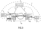
- Figure 3 illustrates a third use of the network entity 1 of Figure 1 , in which the first network element is the upstream packet switch 101, the second network element is the high-speed loopback plug 9 and the network element under supervision is a the packet-switch network 10.
- the Figure 3 differs from the Figure 1 in that the upstream packet switch 101 is connected to a high-speed loopback plug 9 at one port.
- the SDN controller 2 is configured to monitor the upstream packet switch 101 for replicating the packet stream received from the packet stream generator 3.
- the replicating is symbolized on Figure 3 by a dot 12.
- the SDN controller 2 is further configured to configure the upstream packet switch 101 for sending the replication of the packet stream to the high-speed loopback plug 9, and for sending the replicated packet stream to the downstream packet switch 102.
- the SDN controller 2 is further configured to configure the upstream packet switch 101 for iteratively, as a response to receiving a replication of the packet stream from the high-speed loopback plug 9, replicating the replication of the packet stream.
- the SDN controller 2 is further configured to monitor the upstream packet switch 101 for sending the replication of the replication of the packet stream to the high-speed loopback plug 9 and the replicated replication of the packet stream to the downstream packet switch 102.
- the SDN controller 2 is further configured to configure the upstream packet switch 101 for stopping replicating the packet stream after a packet has performed a number N of loops between the upstream packet switch 101 and the high-speed loopback plug 9. Determining that a packet has performed a number N of loops may be performed in one of the various manners described with reference to Figure 1 (i.e. using loopback tags).
- the assumed bit rate of the packet-switch network 10 is a single direction assumed bit-rate, by contrast with the embodiment of Figure 1 wherein the assumed bit rate of the packet-switch network 10 is a bidirectional assumed bit rate.
- the evaluation of assumed bit rate of the packet-switch network 10 can be realized in both directions by implementing a same monitoring of the downstream packet switch 102 as in the upstream packet switch 101, and equipping the downstream packet switch 102 with a high-speed loopback plug 9.
- a loopback counter for each direction could be implemented as a separate counter, e.g. by insertion of an additional MPLS label. Alternatively, one could use the same counter.
- coordination between the packet stream generator 3, packet stream monitor 8 and the SDN controller 2 may be implemented in different ways.
- the packet stream generator 3 can initialize the number of total loops that the SDN controller 2 should perform by, for instance, inserting a VLAN tag with the total number of loops.
- the packet stream generator 3 does not inform the SDN controller 2 of the total number of loops, but the SDN controller 2 will loop the packet stream until reaching the tested bit rate of the network element under supervision.
- the packet stream monitor 8 can beforehand take measure of a reference bit rate of a reference packet stream generated by the packet stream generator 3, without performing any loop for the reference packet stream. Then, the packet stream monitor 8 can trigger the SDN controller 2 to stop performing loopback actions any further when the tested bit rate of a packet stream which has performed loopback actions starts being less than the reference bit rate. This means that the total tested bit rate has just reached the bit rate capacity of the network element under supervision.
- the SDN controller 2 can implement communication interfaces in order to communicate and coordinate loopback actions with the respective packet stream generator 3 and packet stream monitor 8.
- OpenFlow rules or rules in any SDN alternative language can be inserted by the SDN controller 2 on the forwarding tables of the first and second network elements in order to realize the loopbacks.
- the first element is the upstream packet switch 101 and the second element is the downstream packet switch 102.
- the loopback tag may be supported by various formats which are compatibles with SDN networks. In the following, examples are described in which the loopback tag are in Openflow languages, and wherein the first network element and second network element are configured by the SDN controller 2 to obey Openflow rules.
- OpenFlow rules are described using Open vSwitch format.
- the last Openflow rule may not use a variable N, but instead should be replicated as many times as needed with a fix value of N, each inserted in a loopback tag at each loop.
- the forwarding rules can be implemented in very much the same way using MPLS labels, e. g. with actions such as pop_mpls, push_mpls etc.
- MPLS TTL field (8 bits - from 0 to 255) (resp. 8-bit IP TTL field) if the number of loops is under 255. Also, we avoid the TTL from reach 0 in which case, the packets risk to be dropped by the Network Element.
- a new MPLS label is inserted as described previously. But, instead of decreasing/increasing the MPLS label value, the Network Element is programmed to decrease the TTL value at the Outgoing NE before each loopback action. In this case, the previous rules can be written as followings:
- a loopback plug 9 as represented on Figure 2 or on Figure 3 can be replaced by a neighbor network element of the upstream packet switch 101. The traffic is then looped forth and back via the neighbor network element instead of the loopback plug 9.
- One of the advantages of the above described embodiments is to allow testing the tested bit rate of a network element under supervision using a low bit rate packet stream generator 3 instead of using a costly and hard to move hardware high bit rate packet stream generator.
- the packet-switched network 10 is a SDN network and may include one or more domains.
- the data plane technology can be of any type that can be currently supported by SDN technology (e.g. MPLS, IP, Ethernet, etc) or will be supported by SDN technology in the future (e.g. all-optical, WDM, SONET, SDH, and others).
- SDN controller 2 packet stream generator 3 or packet stream monitor 8 are presented above as implemented as separated modules.
- the three components: SDN controller 2, packet stream generator 3 or packet stream monitor 8 could as well be collocated in the same appliance (e.g. the SDN controller and the generator can be part of the same deployed Virtual Network Function (cf. ETSI VNF), or for example, the SDN controller 2 may be a function included in the packet stream generator 3 or in the packet stream monitor 8.
- the three components: SDN controller 2, packet stream generator 3 or packet stream monitor 8 may also be implemented in a unitary manner.
- processing means could be e.g. hardware means like e.g. an ASIC, or a combination of hardware and software means, e.g. an ASIC and an FPGA, or at least one microprocessor and at least one memory with software modules located therein.
- the upstream packet switch 101 and the downstream packet switch 102 may be similar and both configured to loop traffics while inserting/modifying/suppressing loopback tags.
Landscapes
- Engineering & Computer Science (AREA)
- Computer Networks & Wireless Communication (AREA)
- Signal Processing (AREA)
- Data Exchanges In Wide-Area Networks (AREA)
Abstract
Description
- The invention relates to the technical field of generating aggregated bit rate packet stream in a software-defined networks (SDN), especially in packet-switched networks including IP and all flavors of MPLS communication systems.
- Transfer rates of 100 Gbit/s are becoming widely adopted, while vendors are under pressure to introduce even faster network equipments with the expectations of reaching 400 Gbit/s. In this context, tools for traffic generation are essential to quantitative and qualitative evaluations of network equipment performance, e.g. evaluating that a Network Interface Card (NIC) and its associated driver can support the line capacity traffics without any packet loss, verifying that the Quality of Service (QoS) mechanisms work correctly in load condition, etc.
- However, tools for traffic generation at high-speed bit rate, e.g. 100 Gbit/s, are often hardware-based. These are expensive and not very flexible (for example in a fast deployment on an operational network).
- One of the primary metrics of a network equipment performance is the number of packets per second (pps) supported by the network equipment without losing or dropping packets. In order to reach 100 Gbit/s, a traffic generator should transmit 8.13 millions of packets per second (Mpps) with 1500-byte packets. The figure rises upto 148.8 Mpps with minimum-sized (64 byte) packet (thus a packet emitted every 6.7 ns). This cannot be realized by now using a software-based implementation.
- An idea at the basis of the invention is to provide a software packet stream generator generating a high bit rate in order to evaluate a network element dedicated to data stream having high bit rates. Aspects of the invention are based on the idea of using the openness of an SDN-capable network element which allows a
SDN controller 2 to directly provision the forwarding table of the SDN-capable Network Element. - In an embodiment, the invention provides a network entity for providing an aggregated bit rate packet stream in a network element under supervision in a software defined network (SDN), the network entity being destined to be connected to a first network element,
the network entity comprising: - a packet stream generator configured to
- generate a stream of packets having a generating bit rate,
- send the stream of packets to the first network element,
- a software network controller configured to,
- configure the first network element to iteratively pass the stream of packets to a second network element,
- Thank to these features, a network element under supervision having a high bit rate may be evaluated or partially/fully loaded without high bit rate hardware generator. For example, the network may be partially or fully loaded in order to perform some tests under traffic load conditions. The phrase "high bit rate" is understood as a bit rate higher than 50Gbit/s, for example equal to 100Gbit/s. The generating bit rate is comprised between 100Mbit/s and 10Gbit/s. For example, the generating bit rate is equal to 1Gbit/s.
- In embodiments, the network entity may comprise one or more of the following features.
- In an embodiment, the network element is a Label-Switched Router or Label Edge Router (LER) of an MPLS network, wherein the Ping or Traceroute application message comprises an MPLS Ping message or an MPLS Traceroute message. Accordingly, the method may comprise the step of sending the MPLS Ping message or the MPLS Traceroute message from a second Label-Switched Router or Label Edge Router of the an MPLS network.
- In an embodiment, the packet stream generator is a software-based traffic generator.]
- In an embodiment the network entity further comprises:
- a packet stream monitor configured to receive streams of packets from the first network element or respectively the second network element, wherein the software network controller is further configured to
- as a response to determining that a packet of the stream of packets has been looped a determined number N of times from the first network element to the second network element, configure the first network element or respectively the second network element to pass the packet of the stream of packets to the packet stream monitor.
- In an embodiment the software network controller is further configured to:
- determine a monitoring bit rate, wherein the monitoring bit rate is the bit rate of the stream of packets received by the packet stream monitor,
- compare the monitoring bit rate to the generating bit rate.
- In an embodiment, the software network controller is further configured to, as a response to determining that the monitoring bit rate is equal to the generating bit rate, generating a qualification label for the network element under supervision, wherein the qualification label states that the network element under supervision has an assumed high speed bit rate.
- In an embodiment the first network element is an upstream packet switch, the second network element is a downstream packet switch connected to the upstream packet switch by a network link or a network, wherein the network element under supervision is the network link or the network, wherein the stream of packets is passed through the network link or the network the determined number N of times.
- The network link under supervision may be various. For example, the network link may be a virtual link or a physical link. A virtual link designates an abstraction defined in the network for the purpose of traffic engineering. It may or may not correspond to a physical link. It may also correspond to a bundle of physical links. Examples of virtual links include Virtual LANs (VLAN), Label-Switched Paths (LSP) in all flavors of MPLS, Tandem connections in MPLS-TP OAM, IP-Sec (IETF RFC 4303) tunnels, GRE (IETF RFC 2784) tunnels and others.
- The second network element may be configured to pass back the stream of packets to the first network element in various means. In an embodiment, the second network element is a function configured to automatically loopback any traffic. Namely, in an embodiment, the second network element is a high-speed loopback plug connected to a port of the upstream packet switch, wherein the high-speed loopback plug is configured to loop back a packet stream received from a port of the upstream packet switch to the port of the upstream packet switch, wherein the network element under supervision is the upstream packet switch.
- Alternatively, the second network element may be any kind of SDN-capable network element which is configured by the SDN controller monitoring. Namely, in an embodiment, the software network controller is further connected to the second network element, and wherein the software network controller is further configured to control the second network element in order that the second network element is configured to pass back the stream of packets to the first network element, until a packet of the stream of packets has been passed a determined number N of times from the first network element to the second network element.
- In an embodiment, the software network controller is further configured to, prior to control the first network element to pass the stream of packets to the second network element, control the first network element to set a loop counter in header tags of the packets of the stream of packets.
- In an embodiment, the loop counter comprises a triggering limit, which is a function of the number N.
- In an embodiment, the function is equal to N and the loop counter is an incrementing counter configured to stop at the triggering limit. In another embodiment, the function is equal to N and the loop counter is a decrementing counter configured to start at the triggering limit and to stop at zero.
- In an embodiment the software network controller is further configured to control the first network element to replicate the packet stream into a replicated packet stream, and to send the replicated packet stream to the network element under supervision.
- The invention also provides a method for evaluating the assumed bit rate of a packet switch network under test and/or for loading this packet switch network to an amount of traffic load, the method comprising:
- generating a stream of packets having a generating bit rate,
- sending the stream of packets to a first network element,
- monitoring the first network element to iteratively pass the stream of packets to a second network element,
- In embodiments, the method may father comprise one or more of the following features.
- In an embodiment, the method further comprises:
- receiving streams of packets from the first network element or respectively the second network element, and
- as a response to determining that a packet of the stream of packets has been looped a determined number N of times from the first network element to the second network element, passing the packet of the stream of packets to the packet stream monitor.
- In an embodiment, the method further comprises:
- determining a monitoring bit rate, wherein the monitoring bit rate is the bit rate of the stream of packets received by the packet stream monitor,
- comparing the monitoring bit rate to the generating bit rate.
- In an embodiment, the method further comprises:
- passing back the stream of packets to the first network element, until a packet of the stream of packets has been passed a determined number N of times from the first network element to the second network element.
- In an embodiment, the method further comprises:
- setting a loop counter in header tags of the packets of the stream of packets.
- In an embodiment, the method further comprises:
- replicating the packet stream into a replicated packet stream, and to send the replicated packet stream to the network element under supervision.
- These and other aspects of the invention will be apparent from and elucidated with reference to the embodiments described hereinafter, by way of example, with reference to the drawings.
-
Figure 1 is a functional representation of a network entity connected to a network under supervision, according to a first embodiment. -
Figure 2 is a functional representation of a network entity according to a second embodiment. -
Figure 3 is a functional representation of a network entity connected to a network under supervision, according to a third embodiment. - With reference to the Figures, a
network entity 1 is represented. - The
network entity 1 comprises a software-defined network (SDN)controller 2, apacket stream generator 3 and apacket stream monitor 8. - The
packet stream generator 3 is configured to generate streams of packets having a generating bit rate. The generating bit rate is a low bit rate. - The
SDN controller 2 is connected to a first network element and a second network element. The connections between theSDN controller 2 and the first network element and second network element are controlling connections 4 and 5. - The
SDN controller 2 is configured to control the first network element and the second network element. Namely, theSDN controller 2 is configured to set up forwarding tables in the first and second network elements. - With reference to
Figure 1 , thenetwork entity 1 is connected to a packet-switchednetwork 10 which could be as a particular case reduced to anetwork link 11 and the associated network interfaces, the one withinpacket switch 101 and one withinpacket switch 102. Thenetwork entity 1 is further connected to the first network element, which is anupstream packet switch 101, and to the second network element, which is adownstream packet switch 102. - The
SDN controller 2 is configured to control theupstream packet switch 101 and thedownstream packet switch 102. Namely, theSDN controller 2 is configured to set up forwarding tables in theupstream packet switch 101 and thedownstream packet switch 102. - Both the
upstream packet switch 101 and thedownstream packet switch 102 can support up to a minimum common rate capacity (e.g. equal to 100Gbit/s). As represented, theupstream packet switch 101 and thedownstream packet switch 102 connect each other through the packet-switchednetwork 10. Namely, theupstream packet switch 101 and thedownstream packet switch 102 are configured to pass each other packet streams through a high bitrate network link 11 or a packet-switchednetwork 10. - The packet-switched
network 10 is supposed to have an assumed bit rate. The packet-switchednetwork 10 has a tested bit rate. In the example of thefigure 1 , the assumed bit rate is equal to 100 Gbit/s. - In a quantitative approach, the
network entity 1 can be configured to evaluate if the tested bit rate is indeed equal to the assumed bit rate. - In a qualitative approach, the
network entity 1 can be configured to load the packet-switchednetwork 10 at an estimated threshold (e.g. 50% load). - To achieve both quantitative and qualitative approaches, the
packet stream generator 3 is configured to send a stream of packets having the generating bit rate to theupstream packet switch 101. For example, the generating bit rate in thepacket stream generator 3 is configured by controlling of theSDN controller 2 through a controlling link between theSDN controller 2 and thepacket stream generator 3. In the example ofFigure 1 , the generating bit rate is equal to 1Gbit/s. - The
upstream packet switch 101 is configured to pass the stream of packets to thedownstream packet switch 102, and thedownstream packet switch 102 is configured to pass the stream of packets to theupstream packet switch 101 in order that each packet of the stream of packet performs a number N of loops between theupstream packet switch 101 and thedownstream packet switch 102. - Determining if the received packet has performed the number N of loops may be performed in various means.
- In a first example, the
SDN controller 2 can implement an internal loop Counter which is incremented each time the packet stream is looped back at thedownstream packet switch 102. TheSDN controller 2 then sets up thedownstream packet switch 102 for forwarding the packet stream to the packet stream monitor 8 when the counter reaches a parameterized maximum value. In a preferred embodiment further described below, a tag may inserted into the packet by thedownstream packet switch 102 so that theupstream packet switch 101 can differentiate between different loops. - In a second example, the
downstream packet switch 102 is set up by theSDN controller 2 in order to insert a loopback tag in the header of each packet of the stream of packets. - The presence of a loopback tag in the header of a packet of the stream of packet is symbolized on
Figure 1 by a dot 6. - The loopback tag may be a Virtual Local Area Network (VLAN) tag, or a MultiProtocol Label Switching (MPLS) label or the Time-to-Live (TTL) field associated to the IP header (resp. MPLS label), or any customized header which format is supported by the
SDN controller 2 and both theupstream packet switch 101 and thedownstream packet switch 102. - The tag should be inserted after the last VLAN tag or the last MPLS label which is taken into account by the Network Element Quality of Service (QoS) classifier in order to maintain the same QoS treatment for the packets whose header is modified by adding the tag compared to the packets whose header is unchanged.
- The
downstream packet switch 102 is set up by theSDN controller 2 in order to send back a received packet from the packet stream to theupstream packet switch 101 as a response to detecting a loopback tag in the header of the received packet TheSDN controller 2 is further configured to insert and modify the loopback tag in the header of the received packet so thatpacket switch 101 can differentiate between different looped traffics. - The
upstream packet switch 101 is set up by theSDN controller 2 in order to send back a received packet from the packet stream to thedownstream packet switch 102 as a response to detecting a loopback tag in the header of the received packet. - Therefore each packet of the stream of packets passes iteratively through the packet-
switch network 10 in a loop between theupstream packet switch 101 and thedownstream packet switch 102. - In order to avoid that a packet of the stream of packet circulates in an infinite loop between the
upstream packet switch 101 and thedownstream packet switch 102, the loopback tag comprises a defined number N of loops. Thedownstream packet switch 102 is configured by theSDN controller 2 to suppress the loopback tag from the header of a received packet which has performed the defined number N of loops. - The suppression of the loopback tag from the header of a received packet is represented on
Figure 1 by a dot 7. - The loopback tag may comprise a counter which is incremented at each loop until reaching a parameterized maximum value. Alternatively, the counter may be decremented at each loop until reaching a predefined minimum value (e.g. zero or one in the case where the TTL flied is used).
- In a third example, the
packet stream generator 3 can insert the loopback tag which contains a parameter initially set to the total number N of loops to be performed. TheSDN controller 2 inserts a rule at thedownstream packet switch 102 in order to configure thedownstream packet switch 102 to decrease by one value the parameter at each loop back. TheSDN controller 2 is further configured to insert a rule in thedownstream packet switch 102 in order to configure thedownstream packet switch 102 to suppress the loopback tag and to forward the packet stream to thepacket stream monitor 8, as a response to detecting that the parameter of the loopback tag is equal to 0 (resp. 1 - in case of using TTL field). - Another method of stopping the loop process may be used as well instead of defining a defined number N of loops. In such a method, the packet stream monitor 8 detects that the monitored stream bit rate becomes lower than the generating bit rate by comparison to a certain configured threshold. This means than the
network 10 is fully loaded. The idea here is not to measurenetwork 10 assumed bit rate but to fully load this network for some under-load tests for instance. - In such an embodiment, the three components:
SDN controller 2,packet stream generator 3 and packet stream monitor 8 should be synchronized thanks to synchronizing links connecting each other (not represented). In the case the aim is to ensure that the packet-switchednetwork 10 is fully loaded, then the number N of loops is determined in order that the ratio between the assumed bit rate and the generating bit rate is equal or slightly lower to N+1. - In other cases, the operator can decide to load the network at a defined percentage, for example 50%, of its capacity for testing the packet-switched network under defined load conditions.
- In the example of the
figure 1 , the assumed bit rate is equal to 100Gbit/s, the generating bit rate is equal to 1Gbit/s and therefore the number of loops N is equal to 99. - Thanks to the loops performed by packets of the packet stream received from the
packet stream generator 3, N+1 packet substreams of the packets stream, which are generated at different successive generating time instants, are simultaneously circulating on a same path of the packet-switch network 10. Therefore, the loops of the packets acts as an aggregation of the N+1 packet substreams, which results into an aggregation bit rate of the aggregation of the packet substreams. - If the packet-
switch network 10 has indeed the assumed bit rate, then the aggregation bit rate is the sum of bit rates of packet substreams. Each packet substream having the generating bit rate, the aggregation of the packets substreams has an aggregation bit rate equal to the generating bit rate multiplied by thenumber N+ 1. - By contrast, if the packet-
switch network 10 has a tested bit rate which is lower than the assumed bit rate, the aggregation of the packets substreams is clipped in the packet-switch network 10 and therefore the packets substreams are also clipped. - The
downstream packet switch 102 is further configured by theSDN controller 2 to send a packet which has no loopback tag in the header anymore to apacket stream monitor 8. - The packet stream monitor 8 receives a stream of packets whose header has been suppressed.
- The stream of packets whose header has been suppressed corresponds to the stream of packets initially sent by the
upstream packet switch 101 if the packet-switch network 10 has indeed the assumed bit rate. Otherwise, the stream of packets has been clipped, as explained above. - The packet stream monitor 8 has a minimum bit rate capacity equal to the generating bit rate.
- The
SDN controller 2 is configured to determine a monitoring bit rate, which is the bit rate of the stream of packets received by thepacket stream monitor 8. - The
SDN controller 2 determines that the tested bit rate of the packet-switch network 10 is equal to the assumed bit rate of the packet-switch network 10 as a response to determining that the monitoring bit rate is equal to the generating bit rate. - In the example of the
Figure 1 , the generating bit rate is equal to 1Gbit/s, therefore the packet-switch network 10 under supervision of thenetwork entity 1 is determined to have the capacity to support the assumed bit rate if the monitoring bit rate is equal to 1Gbit/s. -
Figure 2 illustrates a second use of thenetwork entity 1 ofFigure 1 . - The
network entity 1 is connected to a first network element, which is in the example ofFigure 2 anupstream packet switch 101. - The
SDN controller 2 is configured to monitor theupstream packet switch 101, as represented by a controlling connection 4. - The
upstream packet switch 101 has a tested switching bit rate. In the example of thefigure 2 , the assumed switching bit rate is equal to 100Gbit/s. - The
network entity 1 is configured to evaluate if the tested switching bit rate is indeed equal to the assumed switching bit rate. - The
upstream packet switch 101 is connected to a plurality of second network elements, which are high-speed loopback plugs 9, each being connected to a port of theupstream packet switch 101, as represented. - A high-speed loopback plug is a network element adapted to be plugged on a port of another network element. The high-speed loopback plug is configured to receive a packet stream from the port and to send it back to the port. The high-speed loopback plug can support packet streams having high bit rate. On the example of
Figure 2 , the high bit rate capacity of the high-speed loopback plugs 9 is equal to 100Gbit/s. - With reference again to
Figure 2 , the control of theupstream packet switch 101 by theSDN controller 2 for evaluating if the tested switching bit rate is equal to the assumed switching bit rate is further described. - The
SDN controller 2 is configured to control theupstream packet switch 101 for, as a response to receiving a packet stream from thepacket stream generator 3, sending the packet stream to a first high-speed loopback plug 9 through a first port of theupstream packet switch 101. - The
SDN controller 2 is further configured to control theupstream packet switch 101 for, as a response to receiving a packet stream from a ith high-speed loopback plug 9, sending the packet stream either to a ith or to a i+1th high-speed loopback plug 9 through a ith or i+1th port of theupstream packet switch 101, wherein "i" denotes for an index of the high-speed loopback plug 9 of the plurality of high-speed loopback plugs 9 of theupstream packet switch 101. - Therefore a packet of the packet stream is looped N times from the
upstream packet switch 101 to one of the high-speed loopback plugs 9. - The
SDN controller 2 is further configured to control theupstream packet switch 101 for, as a response to receiving a packet of the packet stream having performed N loops, send the packet to thepacket stream monitor 8. - Determining if the received packet has performed the number N of loops may be performed in various means previously described with reference to
Figure 1 (i.e. using loopback tags). - Thanks to the loops performed by the packets of the stream of packets received from the
packet stream generator 3, N+1 packets substreams of the stream of packets, which are generated at different successive generating time instants, are simultaneously switched by theupstream packet switch 101. - If the
upstream packet switch 101 has indeed the assumed switching bit rate, then an aggregation bit rate is the sum of the switching bit rates of the packets substreams, otherwise the aggregation bit rate is lower than the sum of the switching bit rates because of the packet stream being clipped. - In a same manner as described with reference to
Figure 1 , theSDN controller 2 is configured to determine that the monitoring bit rate is equal to the generating bit rate, and to deduce that theupstream packet switch 101 has the assumed switching bit rate or not. -
Figure 3 illustrates a third use of thenetwork entity 1 ofFigure 1 , in which the first network element is theupstream packet switch 101, the second network element is the high-speed loopback plug 9 and the network element under supervision is a the packet-switch network 10. - The
Figure 3 differs from theFigure 1 in that theupstream packet switch 101 is connected to a high-speed loopback plug 9 at one port. - By contrast with
Figures 1 and 2 , theSDN controller 2 is configured to monitor theupstream packet switch 101 for replicating the packet stream received from thepacket stream generator 3. The replicating is symbolized onFigure 3 by adot 12. - The
SDN controller 2 is further configured to configure theupstream packet switch 101 for sending the replication of the packet stream to the high-speed loopback plug 9, and for sending the replicated packet stream to thedownstream packet switch 102. - The
SDN controller 2 is further configured to configure theupstream packet switch 101 for iteratively, as a response to receiving a replication of the packet stream from the high-speed loopback plug 9, replicating the replication of the packet stream. TheSDN controller 2 is further configured to monitor theupstream packet switch 101 for sending the replication of the replication of the packet stream to the high-speed loopback plug 9 and the replicated replication of the packet stream to thedownstream packet switch 102. - The
SDN controller 2 is further configured to configure theupstream packet switch 101 for stopping replicating the packet stream after a packet has performed a number N of loops between theupstream packet switch 101 and the high-speed loopback plug 9. Determining that a packet has performed a number N of loops may be performed in one of the various manners described with reference toFigure 1 (i.e. using loopback tags). - With reference to the embodiment of
Figure 3 , the assumed bit rate of the packet-switch network 10 is a single direction assumed bit-rate, by contrast with the embodiment ofFigure 1 wherein the assumed bit rate of the packet-switch network 10 is a bidirectional assumed bit rate. - Evaluating that the assumed bit rate of the packet-
switch network 10 is equal or not to the tested bit rate of the packet-switch network 10 is performed similarly to the evaluating described with reference toFigure 1 . - The evaluation of assumed bit rate of the packet-
switch network 10 can be realized in both directions by implementing a same monitoring of thedownstream packet switch 102 as in theupstream packet switch 101, and equipping thedownstream packet switch 102 with a high-speed loopback plug 9. In this case, a loopback counter for each direction could be implemented as a separate counter, e.g. by insertion of an additional MPLS label. Alternatively, one could use the same counter. - In each previous described embodiment, coordination between the
packet stream generator 3,packet stream monitor 8 and theSDN controller 2 may be implemented in different ways. - For example, the
packet stream generator 3 can initialize the number of total loops that theSDN controller 2 should perform by, for instance, inserting a VLAN tag with the total number of loops. - Alternatively, the
packet stream generator 3 does not inform theSDN controller 2 of the total number of loops, but theSDN controller 2 will loop the packet stream until reaching the tested bit rate of the network element under supervision. For this purpose, the packet stream monitor 8 can beforehand take measure of a reference bit rate of a reference packet stream generated by thepacket stream generator 3, without performing any loop for the reference packet stream. Then, the packet stream monitor 8 can trigger theSDN controller 2 to stop performing loopback actions any further when the tested bit rate of a packet stream which has performed loopback actions starts being less than the reference bit rate. This means that the total tested bit rate has just reached the bit rate capacity of the network element under supervision. - In these cases, the
SDN controller 2 can implement communication interfaces in order to communicate and coordinate loopback actions with the respectivepacket stream generator 3 andpacket stream monitor 8. - In each previous described embodiment, OpenFlow rules or rules in any SDN alternative language, such as for example P4, can be inserted by the
SDN controller 2 on the forwarding tables of the first and second network elements in order to realize the loopbacks. In the example ofFigure 1 the first element is theupstream packet switch 101 and the second element is thedownstream packet switch 102. - The loopback tag may be supported by various formats which are compatibles with SDN networks. In the following, examples are described in which the loopback tag are in Openflow languages, and wherein the first network element and second network element are configured by the
SDN controller 2 to obey Openflow rules. - For the sake of illustration, in the following, OpenFlow rules are described using Open vSwitch format.
- On the
first network element 101, the following rules can be inserted into forwarding tables:- priority=1, in_port=2, actions=in_port
- priority=1, in_port=1, actions=push_vlan:99, output:2
- wherein "port = 2" refers to the port of the
first network element 101 under supervision which is connected to thesecond network element 102 and "port = 1" refers to the port of thefirst network element 101 connected to thepacket stream generator 3.
- On the
second network element 102, the following rules can be inserted into forwarding tables:- priority=1, vlan_tci=0, in_port=2, actions=strip_vlan,output:1
- priority=0, in_port=2, vlan_tci=N, actions= mod_vlan_vid:N-1, in_port
- wherein "port = 2" refers to the port of the
second network element 102 under supervision which is connected to thefirst network element 101 and "port = 1" refers to the port of thesecond network element 102 connected to thepacket stream monitor 8.
- Alternatively, the last Openflow rule may not use a variable N, but instead should be replicated as many times as needed with a fix value of N, each inserted in a loopback tag at each loop.
- Example of such successive replicated Openflow rules are stated below:
- priority=0, in_port=2, vlan_tci=99, actions= mod_vlan_vid:98, in_port
- priority=0, in_port=2, vlan_tci=98, actions= mod_vlan_vid:97, in_port
- etc
- While the above examples are implemented using VLAN tags, the forwarding rules can be implemented in very much the same way using MPLS labels, e. g. with actions such as pop_mpls, push_mpls etc.
- Alternatively, one can use MPLS TTL field (8 bits - from 0 to 255) (resp. 8-bit IP TTL field) if the number of loops is under 255. Also, we avoid the TTL from reach 0 in which case, the packets risk to be dropped by the Network Element. A new MPLS label is inserted as described previously. But, instead of decreasing/increasing the MPLS label value, the Network Element is programmed to decrease the TTL value at the Outgoing NE before each loopback action. In this case, the previous rules can be written as followings:
- In the first network element 101:
- priority=1, in_port=2, actions=in_port
- priority=1,in_port=1,actions=push_mpls:0x8847,set_mpls_ttl:100, output:2
- In the
second network element 102, the following rules can be inserted into forwarding tables:- priority= 1, mpls_ttl=1, in_port=2, actions=pop_mpls, output:1
- priority=0, in port =2, actions= dec_mpls_ttl, in_port
- wherein "port = 2" refers to the port of the
second network element 102 under supervision which is connected to thefirst network element 101 and "port = 1" refers to the port of thesecond network element 102 connected to thepacket stream monitor 8.
- In all previous described embodiments, one can take advantages of existing neighbor network elements of the
upstream packet switch 101. In this case, aloopback plug 9 as represented onFigure 2 or onFigure 3 can be replaced by a neighbor network element of theupstream packet switch 101. The traffic is then looped forth and back via the neighbor network element instead of theloopback plug 9. - One of the advantages of the above described embodiments is to allow testing the tested bit rate of a network element under supervision using a low bit rate
packet stream generator 3 instead of using a costly and hard to move hardware high bit rate packet stream generator. - The number of network links shown is purely illustrative and not limitative.
- The packet-switched
network 10 is a SDN network and may include one or more domains. The data plane technology can be of any type that can be currently supported by SDN technology (e.g. MPLS, IP, Ethernet, etc) or will be supported by SDN technology in the future (e.g. all-optical, WDM, SONET, SDH, and others). - The three components:
SDN controller 2,packet stream generator 3 or packet stream monitor 8 are presented above as implemented as separated modules. In general, the three components:SDN controller 2,packet stream generator 3 or packet stream monitor 8 could as well be collocated in the same appliance (e.g. the SDN controller and the generator can be part of the same deployed Virtual Network Function (cf. ETSI VNF), or for example, theSDN controller 2 may be a function included in thepacket stream generator 3 or in thepacket stream monitor 8. The three components:SDN controller 2,packet stream generator 3 or packet stream monitor 8 may also be implemented in a unitary manner. - Elements such as the processing means could be e.g. hardware means like e.g. an ASIC, or a combination of hardware and software means, e.g. an ASIC and an FPGA, or at least one microprocessor and at least one memory with software modules located therein.
- The invention is not limited to the described embodiments. The appended claims are to be construed as embodying all modification and alternative constructions that may be occurred to one skilled in the art, which fairly fall within the basic teaching here, set forth. Namely, the
upstream packet switch 101 and thedownstream packet switch 102 may be similar and both configured to loop traffics while inserting/modifying/suppressing loopback tags. - The use of the verb "to comprise" or "to include" and its conjugations does not exclude the presence of elements or steps other than those stated in a claim. Furthermore, the use of the article "a" or "an" preceding an element or step does not exclude the presence of a plurality of such elements or steps.
- In the claims, any reference signs placed between parentheses shall not be construed as limiting the scope of the claims.
Claims (15)
- A network entity (1) for providing an aggregated bit rate packet stream in a network element under supervision (11, 101) in a software defined network (SDN), the network entity (1) being destined to be connected to a first network element (101), the network entity (1) comprising:a packet stream generator (3) configured to- generate a stream of packets having a generating bit rate,- send the stream of packets to the first network element (101),a software network controller (2) configured to,the second network element (9, 102) being configured to loop back the stream of packets to the first network element (101), until a packet of the stream of packets has been looped a determined number N of times from the first network element (101) to the second network element (9, 102).- configure the first network element (101) to iteratively pass the stream of packets to a second network element,
- A network entity (1) according to claim 1, wherein the network entity further comprises:a packet stream monitor (8) configured to receive streams of packets from the first network element (101) or respectively the second network element (9, 102), wherein the software network controller (2) is further configured to- as a response to determining that a packet of the stream of packets has been looped a determined number N of times from the first network element (101) to the second network element (9, 102), configure the first network element (101) or respectively the second network element (9, 102) to pass the packet of the stream of packets to the packet stream monitor (8).
- A network entity according to claim 2, wherein the software network controller (2) is further configured to :- determine a monitoring bit rate, wherein the monitoring bit rate is the bit rate of the stream of packets received by the packet stream monitor (8),- compare the monitoring bit rate to the generating bit rate.
- A network entity (1) according to claim 1, wherein the first network element is an upstream packet switch (101), the second network element is a downstream packet switch (102) connected to the upstream packet switch (101) by a network link (11) or a network (10), wherein the network element under supervision is the network link (11) or the network (10), wherein the stream of packets is passed through the network link (11) or the network (10) the determined number N of times.
- A network entity (1) according to claim 1, the second network element is a high-speed loopback plug (9) connected to a port of the upstream packet switch (101), wherein the high-speed loopback plug (9) is configured to loop back a packet stream received from a port of the upstream packet switch (101) to the port of the upstream packet switch (101), wherein the network element under supervision is the upstream packet switch (101).
- A network entity (1) according to claim 1, the software network controller (2) is further connected to the second network element (102), and wherein the software network controller (2) is further configured to control the second network element (102) in order that the second network element (102) is configured to pass back the stream of packets to the first network element (101), until a packet of the stream of packets has been passed a determined number N of times from the first network element (101) to the second network element (102).
- A network entity (1) according to claim 1, wherein the software network controller (2) is further configured to, prior to control the first network element (101) to pass the stream of packets to the second network element (102), control the first network element (101) to set a loop counter in header tags of the packets of the stream of packets.
- A network entity (1) according to claim 7, wherein the loop counter comprises a triggering limit, which is a function of the number N.
- A network entity according to claim 1, wherein the software network controller (2) is further configured to control the first network element (101) to replicate the packet stream into a replicated packet stream, and to send the replicated packet stream to the network element under supervision.
- A method for evaluating the assumed bit rate of a packet switch network under test and/or for loading this packet switch network to an amount of traffic load, the method comprising:- generating a stream of packets having a generating bit rate,- sending the stream of packets to a first network element (101),- monitoring the first network element to iteratively pass the stream of packets to a second network element (102),the second network element (102) being configured to loop back the stream of packets to the first network element, until a packet of the stream of packets has been looped a determined number N of times from the first network element to the second network element.
- A method according to claim 10, further comprising:- receiving streams of packets from the first network element (101) or respectively the second network element (9, 102), and- as a response to determining that a packet of the stream of packets has been looped a determined number N of times from the first network element (101) to the second network element (9, 102), passing the packet of the stream of packets to the packet stream monitor (8).
- A method according to claim 11, further comprising:- determining a monitoring bit rate, wherein the monitoring bit rate is the bit rate of the stream of packets received by the packet stream monitor (8),- comparing the monitoring bit rate to the generating bit rate.
- A method according to claim 10, further comprising:- passing back the stream of packets to the first network element (101), until a packet of the stream of packets has been passed a determined number N of times from the first network element (101) to the second network element (102).
- A method according to claim 10, further comprising:- setting a loop counter in header tags of the packets of the stream of packets.
- A method according to claim 10, further comprising:- replicating the packet stream into a replicated packet stream, and to send the replicated packet stream to the network element under supervision.
Priority Applications (2)
| Application Number | Priority Date | Filing Date | Title |
|---|---|---|---|
| EP17306113.6A EP3451588B1 (en) | 2017-08-30 | 2017-08-30 | A network entity for providing an aggregated bit rate packet stream |
| PCT/EP2018/062514 WO2019042593A1 (en) | 2017-08-30 | 2018-05-15 | A network entity for providing an aggregated bit rate packet stream |
Applications Claiming Priority (1)
| Application Number | Priority Date | Filing Date | Title |
|---|---|---|---|
| EP17306113.6A EP3451588B1 (en) | 2017-08-30 | 2017-08-30 | A network entity for providing an aggregated bit rate packet stream |
Publications (2)
| Publication Number | Publication Date |
|---|---|
| EP3451588A1 true EP3451588A1 (en) | 2019-03-06 |
| EP3451588B1 EP3451588B1 (en) | 2020-04-22 |
Family
ID=59856467
Family Applications (1)
| Application Number | Title | Priority Date | Filing Date |
|---|---|---|---|
| EP17306113.6A Active EP3451588B1 (en) | 2017-08-30 | 2017-08-30 | A network entity for providing an aggregated bit rate packet stream |
Country Status (2)
| Country | Link |
|---|---|
| EP (1) | EP3451588B1 (en) |
| WO (1) | WO2019042593A1 (en) |
Citations (1)
| Publication number | Priority date | Publication date | Assignee | Title |
|---|---|---|---|---|
| US20160248656A1 (en) * | 2015-02-20 | 2016-08-25 | Telefonaktiebolaget L M Ericsson (Publ) | High-precision packet train generation |
-
2017
- 2017-08-30 EP EP17306113.6A patent/EP3451588B1/en active Active
-
2018
- 2018-05-15 WO PCT/EP2018/062514 patent/WO2019042593A1/en not_active Ceased
Patent Citations (1)
| Publication number | Priority date | Publication date | Assignee | Title |
|---|---|---|---|---|
| US20160248656A1 (en) * | 2015-02-20 | 2016-08-25 | Telefonaktiebolaget L M Ericsson (Publ) | High-precision packet train generation |
Non-Patent Citations (1)
| Title |
|---|
| CHI PO-WEN ET AL: "SDNort: A Software Defined Network Testing Framework Using Openflow", 2016 11TH ASIA JOINT CONFERENCE ON INFORMATION SECURITY (ASIAJCIS), IEEE, 4 August 2016 (2016-08-04), pages 100 - 107, XP033023349, DOI: 10.1109/ASIAJCIS.2016.12 * |
Also Published As
| Publication number | Publication date |
|---|---|
| EP3451588B1 (en) | 2020-04-22 |
| WO2019042593A1 (en) | 2019-03-07 |
Similar Documents
| Publication | Publication Date | Title |
|---|---|---|
| Van Adrichem et al. | Fast recovery in software-defined networks | |
| KR100725005B1 (en) | Fast Rerouting Method in Multiprotocol Label Switching Network | |
| US20190109776A1 (en) | Network device service quality detection method and apparatus | |
| US8374095B2 (en) | Connection verification for MPLS label switched paths and pseudowires | |
| US20050281192A1 (en) | Consistency between MPLS forwarding and control planes | |
| US20080031129A1 (en) | Smart Ethernet edge networking system | |
| EP1903725B1 (en) | Packet communication method and packet communication device | |
| EP3208978B1 (en) | Dynamic bandwidth adjustment in packet transport network | |
| US20090010153A1 (en) | Fast remote failure notification | |
| EP2557731A1 (en) | Method and system for independently implementing fault location by intermediate node | |
| CN103490921B (en) | Network protection method, device, lower link point and system | |
| Feng et al. | A ring-based single-link failure recovery approach in SDN data plane | |
| US10389615B2 (en) | Enhanced packet flow monitoring in a network | |
| WO2008132203A2 (en) | Recovering from a failure in a communications network | |
| EP3840309B1 (en) | Sequence number checksum for link state protocols | |
| EP3451588B1 (en) | A network entity for providing an aggregated bit rate packet stream | |
| US11121964B2 (en) | Data path retention during control plane failures in a multiprotocol label switching network | |
| Fang et al. | LDP failure detection and recovery | |
| Fodero et al. | Deterministic communications for protection applications over packet-based wide-area networks | |
| Nur et al. | Gateway redundancy using common address redundancy protocol (CARP) | |
| Bastos et al. | Path recovery algorithm using fast-failover for software-defined networks | |
| Popovic | Redundancy in communication networks for smart grids | |
| Damanik et al. | Implementation of Backoff Algorithm Bidirectional Forwarding Detection (BFD) and MPLS VRF for Fast Recovery Mechanism End-to-End Multi-Circuit (E2E) | |
| Valenti et al. | Experimental investigations on restoration techniques in a wide area Gigabit Ethernet optical test bed based on virtual private LAN service | |
| US12580840B2 (en) | Methods, systems, and computer readable media for link multiplexing and forwarding packets in a test environment |
Legal Events
| Date | Code | Title | Description |
|---|---|---|---|
| PUAI | Public reference made under article 153(3) epc to a published international application that has entered the european phase |
Free format text: ORIGINAL CODE: 0009012 |
|
| STAA | Information on the status of an ep patent application or granted ep patent |
Free format text: STATUS: THE APPLICATION HAS BEEN PUBLISHED |
|
| AK | Designated contracting states |
Kind code of ref document: A1 Designated state(s): AL AT BE BG CH CY CZ DE DK EE ES FI FR GB GR HR HU IE IS IT LI LT LU LV MC MK MT NL NO PL PT RO RS SE SI SK SM TR |
|
| AX | Request for extension of the european patent |
Extension state: BA ME |
|
| RAP1 | Party data changed (applicant data changed or rights of an application transferred) |
Owner name: NOKIA SOLUTIONS AND NETWORKS OY |
|
| STAA | Information on the status of an ep patent application or granted ep patent |
Free format text: STATUS: REQUEST FOR EXAMINATION WAS MADE |
|
| 17P | Request for examination filed |
Effective date: 20190906 |
|
| RBV | Designated contracting states (corrected) |
Designated state(s): AL AT BE BG CH CY CZ DE DK EE ES FI FR GB GR HR HU IE IS IT LI LT LU LV MC MK MT NL NO PL PT RO RS SE SI SK SM TR |
|
| GRAP | Despatch of communication of intention to grant a patent |
Free format text: ORIGINAL CODE: EPIDOSNIGR1 |
|
| STAA | Information on the status of an ep patent application or granted ep patent |
Free format text: STATUS: GRANT OF PATENT IS INTENDED |
|
| RIC1 | Information provided on ipc code assigned before grant |
Ipc: H04L 12/26 20060101AFI20191211BHEP Ipc: H04L 12/715 20130101ALN20191211BHEP |
|
| INTG | Intention to grant announced |
Effective date: 20200108 |
|
| RIC1 | Information provided on ipc code assigned before grant |
Ipc: H04L 12/715 20130101ALN20191217BHEP Ipc: H04L 12/26 20060101AFI20191217BHEP |
|
| GRAS | Grant fee paid |
Free format text: ORIGINAL CODE: EPIDOSNIGR3 |
|
| GRAA | (expected) grant |
Free format text: ORIGINAL CODE: 0009210 |
|
| STAA | Information on the status of an ep patent application or granted ep patent |
Free format text: STATUS: THE PATENT HAS BEEN GRANTED |
|
| AK | Designated contracting states |
Kind code of ref document: B1 Designated state(s): AL AT BE BG CH CY CZ DE DK EE ES FI FR GB GR HR HU IE IS IT LI LT LU LV MC MK MT NL NO PL PT RO RS SE SI SK SM TR |
|
| REG | Reference to a national code |
Ref country code: CH Ref legal event code: EP |
|
| REG | Reference to a national code |
Ref country code: IE Ref legal event code: FG4D |
|
| REG | Reference to a national code |
Ref country code: DE Ref legal event code: R096 Ref document number: 602017015155 Country of ref document: DE |
|
| REG | Reference to a national code |
Ref country code: AT Ref legal event code: REF Ref document number: 1261587 Country of ref document: AT Kind code of ref document: T Effective date: 20200515 |
|
| REG | Reference to a national code |
Ref country code: LT Ref legal event code: MG4D |
|
| REG | Reference to a national code |
Ref country code: NL Ref legal event code: MP Effective date: 20200422 |
|
| PG25 | Lapsed in a contracting state [announced via postgrant information from national office to epo] |
Ref country code: GR Free format text: LAPSE BECAUSE OF FAILURE TO SUBMIT A TRANSLATION OF THE DESCRIPTION OR TO PAY THE FEE WITHIN THE PRESCRIBED TIME-LIMIT Effective date: 20200723 Ref country code: FI Free format text: LAPSE BECAUSE OF FAILURE TO SUBMIT A TRANSLATION OF THE DESCRIPTION OR TO PAY THE FEE WITHIN THE PRESCRIBED TIME-LIMIT Effective date: 20200422 Ref country code: IS Free format text: LAPSE BECAUSE OF FAILURE TO SUBMIT A TRANSLATION OF THE DESCRIPTION OR TO PAY THE FEE WITHIN THE PRESCRIBED TIME-LIMIT Effective date: 20200822 Ref country code: SE Free format text: LAPSE BECAUSE OF FAILURE TO SUBMIT A TRANSLATION OF THE DESCRIPTION OR TO PAY THE FEE WITHIN THE PRESCRIBED TIME-LIMIT Effective date: 20200422 Ref country code: NO Free format text: LAPSE BECAUSE OF FAILURE TO SUBMIT A TRANSLATION OF THE DESCRIPTION OR TO PAY THE FEE WITHIN THE PRESCRIBED TIME-LIMIT Effective date: 20200722 Ref country code: LT Free format text: LAPSE BECAUSE OF FAILURE TO SUBMIT A TRANSLATION OF THE DESCRIPTION OR TO PAY THE FEE WITHIN THE PRESCRIBED TIME-LIMIT Effective date: 20200422 Ref country code: NL Free format text: LAPSE BECAUSE OF FAILURE TO SUBMIT A TRANSLATION OF THE DESCRIPTION OR TO PAY THE FEE WITHIN THE PRESCRIBED TIME-LIMIT Effective date: 20200422 Ref country code: PT Free format text: LAPSE BECAUSE OF FAILURE TO SUBMIT A TRANSLATION OF THE DESCRIPTION OR TO PAY THE FEE WITHIN THE PRESCRIBED TIME-LIMIT Effective date: 20200824 |
|
| REG | Reference to a national code |
Ref country code: AT Ref legal event code: MK05 Ref document number: 1261587 Country of ref document: AT Kind code of ref document: T Effective date: 20200422 |
|
| PG25 | Lapsed in a contracting state [announced via postgrant information from national office to epo] |
Ref country code: BG Free format text: LAPSE BECAUSE OF FAILURE TO SUBMIT A TRANSLATION OF THE DESCRIPTION OR TO PAY THE FEE WITHIN THE PRESCRIBED TIME-LIMIT Effective date: 20200722 Ref country code: LV Free format text: LAPSE BECAUSE OF FAILURE TO SUBMIT A TRANSLATION OF THE DESCRIPTION OR TO PAY THE FEE WITHIN THE PRESCRIBED TIME-LIMIT Effective date: 20200422 Ref country code: HR Free format text: LAPSE BECAUSE OF FAILURE TO SUBMIT A TRANSLATION OF THE DESCRIPTION OR TO PAY THE FEE WITHIN THE PRESCRIBED TIME-LIMIT Effective date: 20200422 Ref country code: RS Free format text: LAPSE BECAUSE OF FAILURE TO SUBMIT A TRANSLATION OF THE DESCRIPTION OR TO PAY THE FEE WITHIN THE PRESCRIBED TIME-LIMIT Effective date: 20200422 |
|
| PG25 | Lapsed in a contracting state [announced via postgrant information from national office to epo] |
Ref country code: AL Free format text: LAPSE BECAUSE OF FAILURE TO SUBMIT A TRANSLATION OF THE DESCRIPTION OR TO PAY THE FEE WITHIN THE PRESCRIBED TIME-LIMIT Effective date: 20200422 |
|
| REG | Reference to a national code |
Ref country code: DE Ref legal event code: R097 Ref document number: 602017015155 Country of ref document: DE |
|
| PG25 | Lapsed in a contracting state [announced via postgrant information from national office to epo] |
Ref country code: EE Free format text: LAPSE BECAUSE OF FAILURE TO SUBMIT A TRANSLATION OF THE DESCRIPTION OR TO PAY THE FEE WITHIN THE PRESCRIBED TIME-LIMIT Effective date: 20200422 Ref country code: DK Free format text: LAPSE BECAUSE OF FAILURE TO SUBMIT A TRANSLATION OF THE DESCRIPTION OR TO PAY THE FEE WITHIN THE PRESCRIBED TIME-LIMIT Effective date: 20200422 Ref country code: AT Free format text: LAPSE BECAUSE OF FAILURE TO SUBMIT A TRANSLATION OF THE DESCRIPTION OR TO PAY THE FEE WITHIN THE PRESCRIBED TIME-LIMIT Effective date: 20200422 Ref country code: SM Free format text: LAPSE BECAUSE OF FAILURE TO SUBMIT A TRANSLATION OF THE DESCRIPTION OR TO PAY THE FEE WITHIN THE PRESCRIBED TIME-LIMIT Effective date: 20200422 Ref country code: IT Free format text: LAPSE BECAUSE OF FAILURE TO SUBMIT A TRANSLATION OF THE DESCRIPTION OR TO PAY THE FEE WITHIN THE PRESCRIBED TIME-LIMIT Effective date: 20200422 Ref country code: ES Free format text: LAPSE BECAUSE OF FAILURE TO SUBMIT A TRANSLATION OF THE DESCRIPTION OR TO PAY THE FEE WITHIN THE PRESCRIBED TIME-LIMIT Effective date: 20200422 Ref country code: CZ Free format text: LAPSE BECAUSE OF FAILURE TO SUBMIT A TRANSLATION OF THE DESCRIPTION OR TO PAY THE FEE WITHIN THE PRESCRIBED TIME-LIMIT Effective date: 20200422 Ref country code: RO Free format text: LAPSE BECAUSE OF FAILURE TO SUBMIT A TRANSLATION OF THE DESCRIPTION OR TO PAY THE FEE WITHIN THE PRESCRIBED TIME-LIMIT Effective date: 20200422 |
|
| PG25 | Lapsed in a contracting state [announced via postgrant information from national office to epo] |
Ref country code: PL Free format text: LAPSE BECAUSE OF FAILURE TO SUBMIT A TRANSLATION OF THE DESCRIPTION OR TO PAY THE FEE WITHIN THE PRESCRIBED TIME-LIMIT Effective date: 20200422 Ref country code: SK Free format text: LAPSE BECAUSE OF FAILURE TO SUBMIT A TRANSLATION OF THE DESCRIPTION OR TO PAY THE FEE WITHIN THE PRESCRIBED TIME-LIMIT Effective date: 20200422 |
|
| PLBE | No opposition filed within time limit |
Free format text: ORIGINAL CODE: 0009261 |
|
| STAA | Information on the status of an ep patent application or granted ep patent |
Free format text: STATUS: NO OPPOSITION FILED WITHIN TIME LIMIT |
|
| 26N | No opposition filed |
Effective date: 20210125 |
|
| PG25 | Lapsed in a contracting state [announced via postgrant information from national office to epo] |
Ref country code: MC Free format text: LAPSE BECAUSE OF FAILURE TO SUBMIT A TRANSLATION OF THE DESCRIPTION OR TO PAY THE FEE WITHIN THE PRESCRIBED TIME-LIMIT Effective date: 20200422 |
|
| REG | Reference to a national code |
Ref country code: CH Ref legal event code: PL |
|
| PG25 | Lapsed in a contracting state [announced via postgrant information from national office to epo] |
Ref country code: LI Free format text: LAPSE BECAUSE OF NON-PAYMENT OF DUE FEES Effective date: 20200831 Ref country code: LU Free format text: LAPSE BECAUSE OF NON-PAYMENT OF DUE FEES Effective date: 20200830 Ref country code: CH Free format text: LAPSE BECAUSE OF NON-PAYMENT OF DUE FEES Effective date: 20200831 |
|
| REG | Reference to a national code |
Ref country code: BE Ref legal event code: MM Effective date: 20200831 |
|
| PG25 | Lapsed in a contracting state [announced via postgrant information from national office to epo] |
Ref country code: SI Free format text: LAPSE BECAUSE OF FAILURE TO SUBMIT A TRANSLATION OF THE DESCRIPTION OR TO PAY THE FEE WITHIN THE PRESCRIBED TIME-LIMIT Effective date: 20200422 |
|
| PG25 | Lapsed in a contracting state [announced via postgrant information from national office to epo] |
Ref country code: FR Free format text: LAPSE BECAUSE OF NON-PAYMENT OF DUE FEES Effective date: 20200831 |
|
| PG25 | Lapsed in a contracting state [announced via postgrant information from national office to epo] |
Ref country code: IE Free format text: LAPSE BECAUSE OF NON-PAYMENT OF DUE FEES Effective date: 20200830 Ref country code: BE Free format text: LAPSE BECAUSE OF NON-PAYMENT OF DUE FEES Effective date: 20200831 |
|
| REG | Reference to a national code |
Ref country code: DE Ref legal event code: R079 Ref document number: 602017015155 Country of ref document: DE Free format text: PREVIOUS MAIN CLASS: H04L0012260000 Ipc: H04L0043000000 |
|
| PG25 | Lapsed in a contracting state [announced via postgrant information from national office to epo] |
Ref country code: TR Free format text: LAPSE BECAUSE OF FAILURE TO SUBMIT A TRANSLATION OF THE DESCRIPTION OR TO PAY THE FEE WITHIN THE PRESCRIBED TIME-LIMIT Effective date: 20200422 Ref country code: MT Free format text: LAPSE BECAUSE OF FAILURE TO SUBMIT A TRANSLATION OF THE DESCRIPTION OR TO PAY THE FEE WITHIN THE PRESCRIBED TIME-LIMIT Effective date: 20200422 Ref country code: CY Free format text: LAPSE BECAUSE OF FAILURE TO SUBMIT A TRANSLATION OF THE DESCRIPTION OR TO PAY THE FEE WITHIN THE PRESCRIBED TIME-LIMIT Effective date: 20200422 |
|
| PG25 | Lapsed in a contracting state [announced via postgrant information from national office to epo] |
Ref country code: MK Free format text: LAPSE BECAUSE OF FAILURE TO SUBMIT A TRANSLATION OF THE DESCRIPTION OR TO PAY THE FEE WITHIN THE PRESCRIBED TIME-LIMIT Effective date: 20200422 |
|
| PGFP | Annual fee paid to national office [announced via postgrant information from national office to epo] |
Ref country code: DE Payment date: 20250702 Year of fee payment: 9 |
|
| PGFP | Annual fee paid to national office [announced via postgrant information from national office to epo] |
Ref country code: GB Payment date: 20250703 Year of fee payment: 9 |