EP3451499A1 - Electrical machine rotor - Google Patents
Electrical machine rotor Download PDFInfo
- Publication number
- EP3451499A1 EP3451499A1 EP18186901.7A EP18186901A EP3451499A1 EP 3451499 A1 EP3451499 A1 EP 3451499A1 EP 18186901 A EP18186901 A EP 18186901A EP 3451499 A1 EP3451499 A1 EP 3451499A1
- Authority
- EP
- European Patent Office
- Prior art keywords
- rotor
- ring sections
- containment sleeve
- sleeve
- reticulated
- Prior art date
- Legal status (The legal status is an assumption and is not a legal conclusion. Google has not performed a legal analysis and makes no representation as to the accuracy of the status listed.)
- Granted
Links
Images



Classifications
-
- H—ELECTRICITY
- H02—GENERATION; CONVERSION OR DISTRIBUTION OF ELECTRIC POWER
- H02K—DYNAMO-ELECTRIC MACHINES
- H02K1/00—Details of the magnetic circuit
- H02K1/06—Details of the magnetic circuit characterised by the shape, form or construction
- H02K1/22—Rotating parts of the magnetic circuit
- H02K1/27—Rotor cores with permanent magnets
- H02K1/2706—Inner rotors
- H02K1/272—Inner rotors the magnetisation axis of the magnets being perpendicular to the rotor axis
- H02K1/274—Inner rotors the magnetisation axis of the magnets being perpendicular to the rotor axis the rotor consisting of two or more circumferentially positioned magnets
- H02K1/2753—Inner rotors the magnetisation axis of the magnets being perpendicular to the rotor axis the rotor consisting of two or more circumferentially positioned magnets the rotor consisting of magnets or groups of magnets arranged with alternating polarity
-
- H—ELECTRICITY
- H02—GENERATION; CONVERSION OR DISTRIBUTION OF ELECTRIC POWER
- H02K—DYNAMO-ELECTRIC MACHINES
- H02K1/00—Details of the magnetic circuit
- H02K1/06—Details of the magnetic circuit characterised by the shape, form or construction
- H02K1/22—Rotating parts of the magnetic circuit
- H02K1/28—Means for mounting or fastening rotating magnetic parts on to, or to, the rotor structures
-
- H—ELECTRICITY
- H02—GENERATION; CONVERSION OR DISTRIBUTION OF ELECTRIC POWER
- H02K—DYNAMO-ELECTRIC MACHINES
- H02K1/00—Details of the magnetic circuit
- H02K1/06—Details of the magnetic circuit characterised by the shape, form or construction
- H02K1/22—Rotating parts of the magnetic circuit
- H02K1/27—Rotor cores with permanent magnets
- H02K1/2706—Inner rotors
- H02K1/272—Inner rotors the magnetisation axis of the magnets being perpendicular to the rotor axis
- H02K1/274—Inner rotors the magnetisation axis of the magnets being perpendicular to the rotor axis the rotor consisting of two or more circumferentially positioned magnets
- H02K1/2753—Inner rotors the magnetisation axis of the magnets being perpendicular to the rotor axis the rotor consisting of two or more circumferentially positioned magnets the rotor consisting of magnets or groups of magnets arranged with alternating polarity
- H02K1/278—Surface mounted magnets; Inset magnets
-
- H—ELECTRICITY
- H02—GENERATION; CONVERSION OR DISTRIBUTION OF ELECTRIC POWER
- H02K—DYNAMO-ELECTRIC MACHINES
- H02K15/00—Processes or apparatus specially adapted for manufacturing, assembling, maintaining or repairing of dynamo-electric machines
- H02K15/02—Processes or apparatus specially adapted for manufacturing, assembling, maintaining or repairing of dynamo-electric machines of stator or rotor bodies
- H02K15/03—Processes or apparatus specially adapted for manufacturing, assembling, maintaining or repairing of dynamo-electric machines of stator or rotor bodies having permanent magnets
-
- H—ELECTRICITY
- H02—GENERATION; CONVERSION OR DISTRIBUTION OF ELECTRIC POWER
- H02K—DYNAMO-ELECTRIC MACHINES
- H02K7/00—Arrangements for handling mechanical energy structurally associated with dynamo-electric machines, e.g. structural association with mechanical driving motors or auxiliary dynamo-electric machines
- H02K7/18—Structural association of electric generators with mechanical driving motors, e.g. with turbines
- H02K7/1807—Rotary generators
- H02K7/1823—Rotary generators structurally associated with turbines or similar engines
-
- F—MECHANICAL ENGINEERING; LIGHTING; HEATING; WEAPONS; BLASTING
- F01—MACHINES OR ENGINES IN GENERAL; ENGINE PLANTS IN GENERAL; STEAM ENGINES
- F01D—NON-POSITIVE DISPLACEMENT MACHINES OR ENGINES, e.g. STEAM TURBINES
- F01D15/00—Adaptations of machines or engines for special use; Combinations of engines with devices driven thereby
- F01D15/10—Adaptations for driving, or combinations with, electric generators
-
- F—MECHANICAL ENGINEERING; LIGHTING; HEATING; WEAPONS; BLASTING
- F05—INDEXING SCHEMES RELATING TO ENGINES OR PUMPS IN VARIOUS SUBCLASSES OF CLASSES F01-F04
- F05D—INDEXING SCHEME FOR ASPECTS RELATING TO NON-POSITIVE-DISPLACEMENT MACHINES OR ENGINES, GAS-TURBINES OR JET-PROPULSION PLANTS
- F05D2220/00—Application
- F05D2220/30—Application in turbines
- F05D2220/32—Application in turbines in gas turbines
-
- H—ELECTRICITY
- H02—GENERATION; CONVERSION OR DISTRIBUTION OF ELECTRIC POWER
- H02K—DYNAMO-ELECTRIC MACHINES
- H02K2201/00—Specific aspects not provided for in the other groups of this subclass relating to the magnetic circuits
- H02K2201/15—Sectional machines
-
- H—ELECTRICITY
- H02—GENERATION; CONVERSION OR DISTRIBUTION OF ELECTRIC POWER
- H02K—DYNAMO-ELECTRIC MACHINES
- H02K2205/00—Specific aspects not provided for in the other groups of this subclass relating to casings, enclosures, supports
- H02K2205/12—Machines characterised by means for reducing windage losses or windage noise
-
- H—ELECTRICITY
- H02—GENERATION; CONVERSION OR DISTRIBUTION OF ELECTRIC POWER
- H02K—DYNAMO-ELECTRIC MACHINES
- H02K2213/00—Specific aspects, not otherwise provided for and not covered by codes H02K2201/00 - H02K2211/00
- H02K2213/03—Machines characterised by numerical values, ranges, mathematical expressions or similar information
Definitions
- the present disclosure relates to a rotor for an electrical machine.
- the electrical machine such as a motor or a generator typically has a rotor that contains a plurality of magnets arranged around a rotor body. As the rotor rotates, a radially outward force is exerted on the magnets. Although the magnets are typically bonded to the rotor body, in high temperature and/or high speed applications, a containment sleeve surrounding the magnets is needed to counteract the exerted radially outward force.
- the containment sleeve can be made of non-magnetic metal.
- the pulsating magnetic field that results from rotation of the rotor produces eddy currents within the sleeve. These generate heat within the containment sleeve and are thus a source of electrical loss.
- carbon fibre composite is sometimes used to form the sleeve.
- the use of carbon fibre composite eliminates the eddy current losses as it is a non-conductive material.
- composite materials are not typically suitable for high temperature applications as the strength of the resin component reduces dramatically above about 220°C. Even with the use of high temperature epoxy or polyimide, such materials are limited to a maximum operating temperature of about 240°C.
- the present disclosure provides a rotor for an electrical machine, the rotor comprising:
- the electrical resistance of the containment sleeve in the axial direction increases, thereby reducing eddy current loss.
- the alternating ring section structure can still provide the sleeve with adequate strength.
- the present disclosure provides a method of producing the containment sleeve according to the first aspect, the method including forming the solid ring sections and the reticulated ring sections alternately in the axial direction by an additive layer manufacturing (ALM) technique.
- ALM additive layer manufacturing
- this technique facilitates the production of reticulated ring sections have relatively complicated reticulation patterns.
- the reticulated ring sections can be formed by such a technique without being supported by external supports.
- the present disclosure provides an electrical machine having the rotor according to the first aspect.
- the present disclosure provides a gas turbine engine have one or more electrical machines according to the third aspect.
- Each reticulated ring section may be formed by an open framework of intersecting strips.
- the intersecting strips may extend between neighbouring solid ring sections, the strips being angled from the axial direction.
- the strips may be angled from the axial direction by up to 45 degrees. This angling facilitates the production of the reticulated ring sections by an ALM technique because external supports for the strips during ALM may not be needed.
- the reticulated ring sections may have an axial length which is about half the axial length of the solid ring sections. This arrangement generally represents a good compromise between enhancing the electrical resistance of the sleeve in the axial direction, while ensuring an adequate containment pressure is applied to the outer surfaces of the magnets by all parts of the containment sleeve.
- the portion of the length of the path occupied by solid material may be no more than 50% of the total length of the path.
- the rotor may further comprise an outer sleeve radially outwardly of the containment sleeve.
- the outer sleeve may form a continuous external surface of the rotor.
- the containment sleeve may be made of metal. In this way, the containment sleeve can have the mechanical strength to constrain the magnets under relatively high speed and/or high temperature (e.g. 220°C or higher).
- a ducted fan gas turbine engine is generally indicated at 10 and has a principal and rotational axis X-X.
- the engine comprises, in axial flow series, an air intake 11, a propulsive fan 12, an intermediate pressure compressor 13, a high-pressure compressor 14, combustion equipment 15, a high-pressure turbine 16, an intermediate pressure turbine 17, a low-pressure turbine 18 and a core engine exhaust nozzle 19.
- a nacelle 21 generally surrounds the engine 10 and defines the intake 11, a bypass duct 22 and a bypass exhaust nozzle 23.
- air entering the intake 11 is accelerated by the fan 12 to produce two air flows: a first air flow A into the intermediate-pressure compressor 13 and a second air flow B which passes through the bypass duct 22 to provide propulsive thrust.
- the intermediate-pressure compressor 13 compresses the air flow A directed into it before delivering that air to the high-pressure compressor 14 where further compression takes place.
- the compressed air exhausted from the high-pressure compressor 14 is directed into the combustion equipment 15 where it is mixed with fuel and the mixture combusted.
- the resultant hot combustion products then expand through, and thereby drive the high, intermediate and low-pressure turbines 16, 17, 18 before being exhausted through the nozzle 19 to provide additional propulsive thrust.
- the high, intermediate and low-pressure turbines respectively drive the high and intermediate-pressure compressors 14, 13 and the fan 12 by suitable interconnecting shafts.
- gas turbine engines to which the present disclosure may be applied may have alternative configurations.
- such engines may have an alternative number of interconnecting shafts (e.g. two) and/or an alternative number of compressors and/or turbines.
- the engine may comprise a gearbox provided in the drive train from a turbine to a compressor and/or fan.
- the gas turbine engine 10 includes one or more electrical machines, such as a motor coupled to the shafts or a generator to power electrical fuel pumps.
- the motor or the generator has a rotor and a stator.
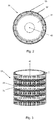
- Figure 2 shows a cross-sectional view of a rotor 30 of such an electrical machine.
- the rotor 30 includes a hollow cylindrical rotor body 31, a circumferential row of magnets 32 arranged around the rotor body 31, and a containment sleeve 33 positioned radially outwardly of the magnets 32.
- the rotor body 31 is coupled to a shaft (not illustrated in Figure 2 ) inserted in its central bore.
- the rotor body 31 When used as a motor, the rotor body 31 is rotated about its axis 40 by the electro-magnetic excitation of coil windings of an external stator (not illustrated in Figure 2 ) to deliver mechanical power to the shaft.
- the shaft When used as a generator, the shaft rotates the rotor body 31 to electro-magnetically excite the coil windings of the stator.
- the magnets 32 which typically are permanent magnets, can be fixed to the rotor body 31 by an adhesive which at least partially retains the magnets 32 to the rotor body 31.
- the containment sleeve 33 extends around the outside of the rotor body 31 and the magnets 32 to cover the outer surfaces of the magnets. It may be fixed in place by a shrink fitting operation, whereby it applies an inwardly-directed retaining pressure on the magnets 32.
- Figure 3 shows a schematic perspective view of the containment sleeve 33.
- the sleeve 33 is typically made of non-magnetic metal, such as InconelTM 718, titanium, or non-magnetic stainless steel, allowing the electrical machine to be operated at high temperatures (e.g. > 220°C, which is above the maximum operating temperature of many composite materials).
- the containment sleeve 33 is thin to reduce the magnetic gap within the magnetic circuit.
- the electrical resistance of the sleeve is increased thereby reducing eddy currents generated within the sleeve 33.
- the sleeve 33 needs to be thick enough to maintain adequate mechanical strength to retain the magnets 32, particularly when the surface speed of the rotor is high due to a high rotational speed and/or a large rotor diameter.
- the thickness T of the sleeve 33 may be about 0.75mm radially.
- the containment sleeve 33 has axially-alternating solid ring sections 34 and reticulated ring sections 35.
- this structure can be produced by an ALM technique.
- ALM technique include (without limitation); electron beam melting (EBM), direct laser deposition (DLD), laser engineered net shaping (LNS), selective laser melting (SLM), direct metal laser sintering (DMLS) and selective laser sintering (SLS).
- EBM electron beam melting
- DLD direct laser deposition
- LNS laser engineered net shaping
- SLM selective laser melting
- DMLS direct metal laser sintering
- SLS selective laser sintering
- the solid ring sections 34 and the reticulated ring sections 35 are alternately formed in the axial direction of the rotor 30.
- the ALM technique allows complicated reticulated sections 35 to be produced with high degrees of accuracy and as near net shapes, thereby reducing the need for any finish-machining.
- FIG 4A shows a developed view of the containment sleeve 33
- Figure 4B shows a detailed view of a part D of the containment sleeve 33 in Figure 4A
- the axial direction is indicated by a thick vertical arrow.
- Each solid ring section 34 is a solid body having no holes, i.e. it is fully dense.
- Each reticulated ring section 35 can be formed by an open framework of intersecting strips 36.
- the intersecting strips 36 extend between neighbouring solid ring sections 34. Conveniently, the strips 36 can be arranged to form a regular lattice.
- the open structure of the reticulated ring sections 35 allows residual non-fused powder from the ALM technique to be easily removed.
- each strip 36 is angled by an amount ⁇ in one direction from the axial direction, or by an amount ⁇ in the other direction from the axial direction.
- the angles ⁇ and ⁇ can be up to 45 degrees.
- adequate support for existing structures must be provided as further layers are added.
- the strips 36 can be self-supporting during ALM. In this way, additional support structures for the strips 36 can be avoided, and post-processing to remove such support structures is not needed.
- Figure 4C shows a cross-sectional view of the containment sleeve along the line A-A in Figure 4A .
- each reticulated ring section 35 has an axial length L1 which is about half the axial length L2 of each solid ring section 34.
- the axial cross-section of the containment sleeve 33 shown in Figure 4C provides a largely uniform contact surface. With such an arrangement, any differences in the stress applied to the surface of the magnets 32 when the containment sleeve 33 is shrink fitted in place may be reduced while, nonetheless, on other axial cross-sections more substantial gaps to segment the containment sleeve 33 may still be provided.
- Figure 4D shows a cross-sectional view of the containment sleeve 33 along the line B-B in Figure 4A , the line B-B being a circumferential path around one of the reticulated ring sections 35 at its axial mid-point.
- the portion of the length of the path occupied by the strips 36 i.e. occupied by solid material
- the reticulated ring sections 35 form substantial bottlenecks to conduction in the axial direction by eddy currents generated within the containment sleeve 33.
- the electric resistance of the containment sleeve 33 increases in this direction, thereby reducing the eddy currents and the impact of eddy current loss on the performance of the rotor 30.
- the containment sleeve 33 can help to achieve low eddy current loss and good mechanical strength, even at high operating temperatures. Moreover, it can conveniently be produced by ALM.
- Figure 5A shows a developed view of a variant of the containment sleeve 33A
- Figure 5B shows an axial cross-sectional view of the containment sleeve 33A along the line C-C in Figure 5A
- the rotor includes an outer sleeve 37 positioned radially outwardly of the containment sleeve 33A.
- the outer sleeve 37 forms a continuous external surface of the rotor.
- the open framework of the reticulated ring sections 35 may cause turbulence in the air gap between the rotor and the stator.
- the outer sleeve 37 may be substantially thinner than the containment sleeve 33 as it is non-structural, and/or it may be made of non-conductive material (e.g. resin) to avoid eddy currents forming therein.
Landscapes
- Engineering & Computer Science (AREA)
- Power Engineering (AREA)
- Manufacturing & Machinery (AREA)
- Permanent Field Magnets Of Synchronous Machinery (AREA)
- Manufacture Of Motors, Generators (AREA)
Abstract

Description
- The present disclosure relates to a rotor for an electrical machine.
- The electrical machine such as a motor or a generator typically has a rotor that contains a plurality of magnets arranged around a rotor body. As the rotor rotates, a radially outward force is exerted on the magnets. Although the magnets are typically bonded to the rotor body, in high temperature and/or high speed applications, a containment sleeve surrounding the magnets is needed to counteract the exerted radially outward force.
- The containment sleeve can be made of non-magnetic metal. However, the pulsating magnetic field that results from rotation of the rotor produces eddy currents within the sleeve. These generate heat within the containment sleeve and are thus a source of electrical loss.
- Thus in relatively low temperature applications (i.e. < 220°C) carbon fibre composite is sometimes used to form the sleeve. The use of carbon fibre composite eliminates the eddy current losses as it is a non-conductive material. However, composite materials are not typically suitable for high temperature applications as the strength of the resin component reduces dramatically above about 220°C. Even with the use of high temperature epoxy or polyimide, such materials are limited to a maximum operating temperature of about 240°C.
- It would be desirable to provide a rotor that reduces eddy current loss.
- Accordingly, in a first aspect, the present disclosure provides a rotor for an electrical machine, the rotor comprising:
- a rotor body;
- one or more magnets arranged around the rotor body; and
- a non-magnetic containment sleeve positioned radially outwardly of the one or more magnets,
- the containment sleeve having axially-alternating solid ring sections and reticulated ring sections.
- By segmenting the containment sleeve in the axial direction with the reticulated ring sections, the electrical resistance of the containment sleeve in the axial direction increases, thereby reducing eddy current loss. However, the alternating ring section structure can still provide the sleeve with adequate strength.
- In a second aspect, the present disclosure provides a method of producing the containment sleeve according to the first aspect, the method including forming the solid ring sections and the reticulated ring sections alternately in the axial direction by an additive layer manufacturing (ALM) technique.
- Advantageously, this technique facilitates the production of reticulated ring sections have relatively complicated reticulation patterns.
- The reticulated ring sections can be formed by such a technique without being supported by external supports.
- In a third aspect, the present disclosure provides an electrical machine having the rotor according to the first aspect.
- In a fourth aspect, the present disclosure provides a gas turbine engine have one or more electrical machines according to the third aspect.
- Optional features of the present disclosure will now be set out. These are applicable singly or in any combination with any aspect of the present disclosure.
- Each reticulated ring section may be formed by an open framework of intersecting strips. For example, the intersecting strips may extend between neighbouring solid ring sections, the strips being angled from the axial direction. In this case, the strips may be angled from the axial direction by up to 45 degrees. This angling facilitates the production of the reticulated ring sections by an ALM technique because external supports for the strips during ALM may not be needed.
- The reticulated ring sections may have an axial length which is about half the axial length of the solid ring sections. This arrangement generally represents a good compromise between enhancing the electrical resistance of the sleeve in the axial direction, while ensuring an adequate containment pressure is applied to the outer surfaces of the magnets by all parts of the containment sleeve.
- On a circumferential path around each reticulated ring section at its axial mid-point, the portion of the length of the path occupied by solid material may be no more than 50% of the total length of the path. With such a configuration, the electrical resistance of the containment sleeve in the axial direction may be substantially increased, thereby reducing the eddy current loss.
- The rotor may further comprise an outer sleeve radially outwardly of the containment sleeve. The outer sleeve may form a continuous external surface of the rotor. An advantage of providing the outer sleeve is to reduce windage losses caused by the openings of the reticulated ring sections.
- The containment sleeve may be made of metal. In this way, the containment sleeve can have the mechanical strength to constrain the magnets under relatively high speed and/or high temperature (e.g. 220°C or higher).
- Embodiments of the present disclosure will now be described by way of example with reference to the accompanying drawings in which:
-
Figure 1 shows a longitudinal cross-section through a ducted fan gas turbine engine; -
Figure 2 shows a cross-sectional view of a rotor of an electrical machine of the gas turbine engine ofFigure 1 ; -
Figure 3 shows a schematic perspective view of a containment sleeve of the rotor ofFigure 2 ; -
Figure 4A shows a schematic developed view of the containment sleeve of theFigure 3 ; -
Figure 4B shows a detailed view of a part D of the containment sleeve inFigure 4A ; -
Figure 4C shows a cross-sectional view of the containment sleeve along the line A-A in -
Figure 4A ; -
Figure 4D shows a cross-sectional view of the containment sleeve along the line B-B in -
Figure 4A ; -
Figure 5A shows a schematic developed view of a variant of the containment sleeve; and -
Figure 5B shows a cross-sectional view of the containment sleeve along the line C-C in -
Figure 5A . - With reference to
Figure 1 , a ducted fan gas turbine engine is generally indicated at 10 and has a principal and rotational axis X-X. The engine comprises, in axial flow series, anair intake 11, apropulsive fan 12, anintermediate pressure compressor 13, a high-pressure compressor 14,combustion equipment 15, a high-pressure turbine 16, anintermediate pressure turbine 17, a low-pressure turbine 18 and a coreengine exhaust nozzle 19. Anacelle 21 generally surrounds theengine 10 and defines theintake 11, abypass duct 22 and abypass exhaust nozzle 23. - During operation, air entering the
intake 11 is accelerated by thefan 12 to produce two air flows: a first air flow A into the intermediate-pressure compressor 13 and a second air flow B which passes through thebypass duct 22 to provide propulsive thrust. The intermediate-pressure compressor 13 compresses the air flow A directed into it before delivering that air to the high-pressure compressor 14 where further compression takes place. - The compressed air exhausted from the high-
pressure compressor 14 is directed into thecombustion equipment 15 where it is mixed with fuel and the mixture combusted. The resultant hot combustion products then expand through, and thereby drive the high, intermediate and low-pressure turbines nozzle 19 to provide additional propulsive thrust. The high, intermediate and low-pressure turbines respectively drive the high and intermediate-pressure compressors fan 12 by suitable interconnecting shafts. - Other gas turbine engines to which the present disclosure may be applied may have alternative configurations. By way of example such engines may have an alternative number of interconnecting shafts (e.g. two) and/or an alternative number of compressors and/or turbines. Further the engine may comprise a gearbox provided in the drive train from a turbine to a compressor and/or fan.
- The
gas turbine engine 10 includes one or more electrical machines, such as a motor coupled to the shafts or a generator to power electrical fuel pumps. The motor or the generator has a rotor and a stator.Figure 2 shows a cross-sectional view of arotor 30 of such an electrical machine. Therotor 30 includes a hollowcylindrical rotor body 31, a circumferential row ofmagnets 32 arranged around therotor body 31, and acontainment sleeve 33 positioned radially outwardly of themagnets 32. Therotor body 31 is coupled to a shaft (not illustrated inFigure 2 ) inserted in its central bore. When used as a motor, therotor body 31 is rotated about itsaxis 40 by the electro-magnetic excitation of coil windings of an external stator (not illustrated inFigure 2 ) to deliver mechanical power to the shaft. When used as a generator, the shaft rotates therotor body 31 to electro-magnetically excite the coil windings of the stator. - The
magnets 32, which typically are permanent magnets, can be fixed to therotor body 31 by an adhesive which at least partially retains themagnets 32 to therotor body 31. - To further assure the retention of the
magnets 32, thecontainment sleeve 33 extends around the outside of therotor body 31 and themagnets 32 to cover the outer surfaces of the magnets. It may be fixed in place by a shrink fitting operation, whereby it applies an inwardly-directed retaining pressure on themagnets 32. -
Figure 3 shows a schematic perspective view of thecontainment sleeve 33. Thesleeve 33 is typically made of non-magnetic metal, such as Inconel™ 718, titanium, or non-magnetic stainless steel, allowing the electrical machine to be operated at high temperatures (e.g. > 220°C, which is above the maximum operating temperature of many composite materials). - The
containment sleeve 33 is thin to reduce the magnetic gap within the magnetic circuit. In addition, by making the sleeve thin, the electrical resistance of the sleeve is increased thereby reducing eddy currents generated within thesleeve 33. On the other hand, thesleeve 33 needs to be thick enough to maintain adequate mechanical strength to retain themagnets 32, particularly when the surface speed of the rotor is high due to a high rotational speed and/or a large rotor diameter. In typical applications, the thickness T of thesleeve 33 may be about 0.75mm radially. - The
containment sleeve 33 has axially-alternatingsolid ring sections 34 andreticulated ring sections 35. Conveniently, this structure can be produced by an ALM technique. In such techniques, a component is built up layer by layer until the 3D component is defined. Specific examples of the ALM technique include (without limitation); electron beam melting (EBM), direct laser deposition (DLD), laser engineered net shaping (LNS), selective laser melting (SLM), direct metal laser sintering (DMLS) and selective laser sintering (SLS). During ALM, thesolid ring sections 34 and thereticulated ring sections 35 are alternately formed in the axial direction of therotor 30. The ALM technique allows complicatedreticulated sections 35 to be produced with high degrees of accuracy and as near net shapes, thereby reducing the need for any finish-machining. -
Figure 4A shows a developed view of thecontainment sleeve 33, andFigure 4B shows a detailed view of a part D of thecontainment sleeve 33 inFigure 4A . InFigure 4A , the axial direction is indicated by a thick vertical arrow. Eachsolid ring section 34 is a solid body having no holes, i.e. it is fully dense. Eachreticulated ring section 35, by contrast, can be formed by an open framework of intersecting strips 36. The intersecting strips 36 extend between neighbouringsolid ring sections 34. Conveniently, thestrips 36 can be arranged to form a regular lattice. The open structure of thereticulated ring sections 35 allows residual non-fused powder from the ALM technique to be easily removed. - As shown in
Figure 4B , eachstrip 36 is angled by an amount α in one direction from the axial direction, or by an amount β in the other direction from the axial direction. The angles α and β can be up to 45 degrees. The strips can all be inclined by the same amount (e.g. α = β), or some strips can be inclined differently to others (e.g. α ≠ β so that all the strips inclined in one direction are angled differently to all those inclined in the opposite direction). In order to produce thecontainment sleeve 33 by ALM, adequate support for existing structures must be provided as further layers are added. Advantageously, by angling eachstrip 36 from the axial direction by no more than 45 degrees, thestrips 36 can be self-supporting during ALM. In this way, additional support structures for thestrips 36 can be avoided, and post-processing to remove such support structures is not needed. -
Figure 4C shows a cross-sectional view of the containment sleeve along the line A-A inFigure 4A . With reference toFigure 4A and4C , eachreticulated ring section 35 has an axial length L1 which is about half the axial length L2 of eachsolid ring section 34. Advantageously, the axial cross-section of thecontainment sleeve 33 shown inFigure 4C provides a largely uniform contact surface. With such an arrangement, any differences in the stress applied to the surface of themagnets 32 when thecontainment sleeve 33 is shrink fitted in place may be reduced while, nonetheless, on other axial cross-sections more substantial gaps to segment thecontainment sleeve 33 may still be provided. - In particular,
Figure 4D shows a cross-sectional view of thecontainment sleeve 33 along the line B-B inFigure 4A , the line B-B being a circumferential path around one of thereticulated ring sections 35 at its axial mid-point. As shown inFigure 4D , the portion of the length of the path occupied by the strips 36 (i.e. occupied by solid material) is no more than 50% of the total length of the path. Thus thereticulated ring sections 35 form substantial bottlenecks to conduction in the axial direction by eddy currents generated within thecontainment sleeve 33. As a result, the electric resistance of thecontainment sleeve 33 increases in this direction, thereby reducing the eddy currents and the impact of eddy current loss on the performance of therotor 30. - In summary, the
containment sleeve 33 can help to achieve low eddy current loss and good mechanical strength, even at high operating temperatures. Moreover, it can conveniently be produced by ALM. -
Figure 5A shows a developed view of a variant of thecontainment sleeve 33A, andFigure 5B shows an axial cross-sectional view of thecontainment sleeve 33A along the line C-C inFigure 5A . In this variant, the rotor includes anouter sleeve 37 positioned radially outwardly of thecontainment sleeve 33A. Theouter sleeve 37 forms a continuous external surface of the rotor. - Without such an
outer sleeve 37, the open framework of thereticulated ring sections 35 may cause turbulence in the air gap between the rotor and the stator. By providing theouter sleeve 37, the windage losses caused by this turbulence may be reduced. Theouter sleeve 37 may be substantially thinner than thecontainment sleeve 33 as it is non-structural, and/or it may be made of non-conductive material (e.g. resin) to avoid eddy currents forming therein. - While the invention has been described in conjunction with the exemplary embodiments described above, many equivalent modifications and variations will be apparent to those skilled in the art when given this disclosure. Accordingly, the exemplary embodiments of the invention set forth above are considered to be illustrative and not limiting.
Claims (11)
- A rotor (30) for an electrical machine, the rotor comprising:a rotor body (31);one or more magnets (32) arranged around the rotor body; anda non-magnetic containment sleeve (33, 33A) positioned radially outwardly of the one or more magnets,the containment sleeve having axially-alternating solid ring sections (34) and reticulated ring sections (35).
- The rotor according to claim 1, wherein each reticulated ring section is formed by an open framework of intersecting strips (36).
- The rotor according to claim 2, wherein the intersecting strips extend between neighbouring solid ring sections, the strips being angled from the axial direction.
- The rotor according to claim 3, wherein the strips are angled from the axial direction by up to 45 degrees.
- The rotor according to any one of the previous claims, wherein the reticulated ring sections have an axial length (L1) which is about half the axial length (L2) of the solid ring sections.
- The rotor according to any one of the previous claims, wherein, on a circumferential path around each reticulated ring section at its axial mid-point, the portion of the length of the path occupied by solid material is no more than 50% of the total length of the path.
- The rotor according to any one of the previous claims, further comprising an outer sleeve (37) radially outwardly of the containment sleeve (33A), the outer sleeve forming a continuous external surface of the rotor.
- The rotor according to any one of the previous claims, wherein the containment sleeve is made of metal.
- A method of producing the containment sleeve according to any one of the previous claims, the method including forming the solid ring sections and the reticulated ring sections alternately in the axial direction by an additive layer manufacturing technique.
- An electrical machine having the rotor according to any one of claims 1 to 8.
- A gas turbine engine (10) having one or more electrical machines according to claim 10.
Applications Claiming Priority (1)
| Application Number | Priority Date | Filing Date | Title |
|---|---|---|---|
| GBGB1714242.3A GB201714242D0 (en) | 2017-09-05 | 2017-09-05 | Electrical machine rotor |
Publications (2)
| Publication Number | Publication Date |
|---|---|
| EP3451499A1 true EP3451499A1 (en) | 2019-03-06 |
| EP3451499B1 EP3451499B1 (en) | 2020-02-19 |
Family
ID=60050649
Family Applications (1)
| Application Number | Title | Priority Date | Filing Date |
|---|---|---|---|
| EP18186901.7A Active EP3451499B1 (en) | 2017-09-05 | 2018-08-01 | Electrical machine rotor |
Country Status (3)
| Country | Link |
|---|---|
| US (1) | US11025112B2 (en) |
| EP (1) | EP3451499B1 (en) |
| GB (1) | GB201714242D0 (en) |
Families Citing this family (10)
| Publication number | Priority date | Publication date | Assignee | Title |
|---|---|---|---|---|
| KR101668660B1 (en) * | 2015-01-15 | 2016-10-24 | 하남전기주식회사 | Rotor for Motor |
| JP7293701B2 (en) * | 2019-02-08 | 2023-06-20 | 株式会社デンソー | Rotating electric machine |
| DE102019210627A1 (en) * | 2019-07-18 | 2021-01-21 | Robert Bosch Gmbh | Rotor device |
| DE102019212446B4 (en) | 2019-08-20 | 2026-03-12 | Robert Bosch Gmbh | Method and computing unit for controlling at least one drive unit or at least one deflection unit of a microscanner device |
| US11489386B2 (en) | 2019-12-18 | 2022-11-01 | Ge Aviation Systems Llc | Wet and dry cavity generator systems and methods of manufacturing the same |
| CN113014013B (en) * | 2019-12-20 | 2023-06-09 | 新疆金风科技股份有限公司 | Rotor brackets, rotors, motors and wind turbines |
| US20220416620A1 (en) * | 2021-06-29 | 2022-12-29 | Rolls-Royce Corporation | Electric generator with isolated rotor magnets |
| EP4125185A1 (en) * | 2021-07-30 | 2023-02-01 | Siemens Aktiengesellschaft | Permanent magnet |
| US12088146B2 (en) * | 2021-08-24 | 2024-09-10 | GM Global Technology Operations LLC | Rotor for an electric machine, electric machine for a vehicle, and vehicle |
| US12107459B2 (en) * | 2022-03-25 | 2024-10-01 | Beta Air Llc | Rotor for an electric aircraft motor comprising a plurality of magnets |
Citations (7)
| Publication number | Priority date | Publication date | Assignee | Title |
|---|---|---|---|---|
| JPH11215779A (en) * | 1998-01-27 | 1999-08-06 | Shibaura Mechatronics Corp | Motor rotor |
| JP2001231200A (en) * | 2000-02-17 | 2001-08-24 | Yaskawa Electric Corp | Protection structure for permanent magnet rotor |
| US20030184185A1 (en) * | 2002-03-27 | 2003-10-02 | Mitsubishi Denki Kabushiki Kaisha | Rotor for synchronous induction motor, manufacturing method and die thereof, and compressor |
| DE102011089058A1 (en) * | 2011-12-19 | 2013-06-20 | Robert Bosch Gmbh | Rotor for brushless permanent magnet electric machine, has two annular portions that are separated by lining structure in which recesses and ridges are provided |
| JP2013188005A (en) * | 2012-03-07 | 2013-09-19 | Mitsubishi Electric Corp | Magnet mounted rotor |
| EP3068019A2 (en) * | 2015-03-13 | 2016-09-14 | Rolls-Royce plc | Sleeve for an electrical machine |
| US20160359394A1 (en) * | 2015-06-04 | 2016-12-08 | Calnetix Technologies Llc | Reducing high frequency losses in an electric machine |
Family Cites Families (11)
| Publication number | Priority date | Publication date | Assignee | Title |
|---|---|---|---|---|
| CN1126900A (en) | 1994-06-07 | 1996-07-17 | 陈启星 | Magnetic sleeve-type motor and ammonia-refrigerated closed compressor |
| JP3369024B2 (en) | 1995-04-14 | 2003-01-20 | 松下電器産業株式会社 | Permanent magnet rotor and its manufacturing method |
| BR9504941A (en) | 1995-11-13 | 1997-10-21 | Brasil Compressores Sa | Rotor cover for electric motor |
| US20030193258A1 (en) | 2002-04-16 | 2003-10-16 | Reiter Frederick B. | Composite powder metal rotor sleeve |
| GB0507217D0 (en) | 2005-04-09 | 2005-05-18 | Rolls Royce Plc | A rotor for an electrical machine |
| US8040007B2 (en) * | 2008-07-28 | 2011-10-18 | Direct Drive Systems, Inc. | Rotor for electric machine having a sleeve with segmented layers |
| CN103312069B (en) | 2012-03-14 | 2016-08-03 | 珠海格力电器股份有限公司 | Motor permanent magnet fixing structure, fixing method and motor comprising structure |
| US9130437B1 (en) | 2012-07-12 | 2015-09-08 | Sergey Pulnikov | Method of manufacturing multilayer metal wire or ribbon bandage over operational zone of rotor |
| US8878409B2 (en) | 2012-09-13 | 2014-11-04 | Hamilton Sundstrand Space Systems International, Inc. | Containment band for permanent magnet generator |
| US10033236B2 (en) * | 2014-07-23 | 2018-07-24 | Lockheed Martin Corporation | Vacuum gap generators and motors |
| EP3131189B1 (en) * | 2015-08-12 | 2018-08-01 | Siemens Aktiengesellschaft | Rotor of an electric machine |
-
2017
- 2017-09-05 GB GBGB1714242.3A patent/GB201714242D0/en not_active Ceased
-
2018
- 2018-07-20 US US16/041,148 patent/US11025112B2/en active Active
- 2018-08-01 EP EP18186901.7A patent/EP3451499B1/en active Active
Patent Citations (7)
| Publication number | Priority date | Publication date | Assignee | Title |
|---|---|---|---|---|
| JPH11215779A (en) * | 1998-01-27 | 1999-08-06 | Shibaura Mechatronics Corp | Motor rotor |
| JP2001231200A (en) * | 2000-02-17 | 2001-08-24 | Yaskawa Electric Corp | Protection structure for permanent magnet rotor |
| US20030184185A1 (en) * | 2002-03-27 | 2003-10-02 | Mitsubishi Denki Kabushiki Kaisha | Rotor for synchronous induction motor, manufacturing method and die thereof, and compressor |
| DE102011089058A1 (en) * | 2011-12-19 | 2013-06-20 | Robert Bosch Gmbh | Rotor for brushless permanent magnet electric machine, has two annular portions that are separated by lining structure in which recesses and ridges are provided |
| JP2013188005A (en) * | 2012-03-07 | 2013-09-19 | Mitsubishi Electric Corp | Magnet mounted rotor |
| EP3068019A2 (en) * | 2015-03-13 | 2016-09-14 | Rolls-Royce plc | Sleeve for an electrical machine |
| US20160359394A1 (en) * | 2015-06-04 | 2016-12-08 | Calnetix Technologies Llc | Reducing high frequency losses in an electric machine |
Also Published As
| Publication number | Publication date |
|---|---|
| US20190074739A1 (en) | 2019-03-07 |
| US11025112B2 (en) | 2021-06-01 |
| GB201714242D0 (en) | 2017-10-18 |
| EP3451499B1 (en) | 2020-02-19 |
Similar Documents
| Publication | Publication Date | Title |
|---|---|---|
| US11025112B2 (en) | Electrical machine rotor | |
| JP6655893B2 (en) | Permanent magnet machine | |
| US7603864B2 (en) | Blade tip electric machine | |
| JP6507246B2 (en) | Method for manufacturing a rotor blade and blade realized by such method | |
| US9963981B2 (en) | Pitch change mechanism for shrouded fan with low fan pressure ratio | |
| US20100090557A1 (en) | Fault tolerant permanent magnet machine | |
| US10823061B2 (en) | Engine air inlet having a double-panel heated wall | |
| US10122228B2 (en) | Sleeve for an electrical machine | |
| WO2015080700A1 (en) | Generator for an aircraft | |
| US11070101B2 (en) | Method and apparatus for cooling an rotor assembly | |
| US20190173335A1 (en) | Switched reluctance machine | |
| US11143041B2 (en) | Turbine have a first and second rotor disc and a first and second cooling fluid conduit wherein the second cooling fluid conduit is extended through an annular axially extended bore having a radially outer extent defined by a radially innermost surface of the rotor discs | |
| Duffy et al. | Design, analysis, and testing of the HEMM cryocooler linear motor | |
| EP3467320A1 (en) | A bladed disk | |
| KR20190032216A (en) | Electric machine comprising a stator provided with an inner tubular sleeve | |
| EP3121940A1 (en) | A ring for an electric machine | |
| EP4391307A1 (en) | Electrical machine having stator sleeve | |
| US20250246956A1 (en) | Magnet retention in exterior rotor electric machines | |
| US20240235289A1 (en) | Permanent magnet for an electric machine and method of making the same | |
| US10557364B2 (en) | Two pieces stator inner shroud | |
| CN112152353B (en) | Permanent magnet machine | |
| JP2014171383A (en) | Generator lead system | |
| EP3490108B1 (en) | Electrical machine | |
| US20190326789A1 (en) | Permanent magnet machine | |
| CN117097076A (en) | Air gap cooling system for electric motors |
Legal Events
| Date | Code | Title | Description |
|---|---|---|---|
| PUAI | Public reference made under article 153(3) epc to a published international application that has entered the european phase |
Free format text: ORIGINAL CODE: 0009012 |
|
| STAA | Information on the status of an ep patent application or granted ep patent |
Free format text: STATUS: THE APPLICATION HAS BEEN PUBLISHED |
|
| AK | Designated contracting states |
Kind code of ref document: A1 Designated state(s): AL AT BE BG CH CY CZ DE DK EE ES FI FR GB GR HR HU IE IS IT LI LT LU LV MC MK MT NL NO PL PT RO RS SE SI SK SM TR |
|
| AX | Request for extension of the european patent |
Extension state: BA ME |
|
| STAA | Information on the status of an ep patent application or granted ep patent |
Free format text: STATUS: REQUEST FOR EXAMINATION WAS MADE |
|
| 17P | Request for examination filed |
Effective date: 20190321 |
|
| RBV | Designated contracting states (corrected) |
Designated state(s): AL AT BE BG CH CY CZ DE DK EE ES FI FR GB GR HR HU IE IS IT LI LT LU LV MC MK MT NL NO PL PT RO RS SE SI SK SM TR |
|
| GRAP | Despatch of communication of intention to grant a patent |
Free format text: ORIGINAL CODE: EPIDOSNIGR1 |
|
| STAA | Information on the status of an ep patent application or granted ep patent |
Free format text: STATUS: GRANT OF PATENT IS INTENDED |
|
| INTG | Intention to grant announced |
Effective date: 20191115 |
|
| GRAS | Grant fee paid |
Free format text: ORIGINAL CODE: EPIDOSNIGR3 |
|
| GRAA | (expected) grant |
Free format text: ORIGINAL CODE: 0009210 |
|
| STAA | Information on the status of an ep patent application or granted ep patent |
Free format text: STATUS: THE PATENT HAS BEEN GRANTED |
|
| AK | Designated contracting states |
Kind code of ref document: B1 Designated state(s): AL AT BE BG CH CY CZ DE DK EE ES FI FR GB GR HR HU IE IS IT LI LT LU LV MC MK MT NL NO PL PT RO RS SE SI SK SM TR |
|
| RAP2 | Party data changed (patent owner data changed or rights of a patent transferred) |
Owner name: ROLLS-ROYCE PLC |
|
| REG | Reference to a national code |
Ref country code: CH Ref legal event code: EP |
|
| REG | Reference to a national code |
Ref country code: DE Ref legal event code: R096 Ref document number: 602018002520 Country of ref document: DE |
|
| REG | Reference to a national code |
Ref country code: AT Ref legal event code: REF Ref document number: 1236076 Country of ref document: AT Kind code of ref document: T Effective date: 20200315 |
|
| REG | Reference to a national code |
Ref country code: IE Ref legal event code: FG4D |
|
| REG | Reference to a national code |
Ref country code: NL Ref legal event code: MP Effective date: 20200219 |
|
| PG25 | Lapsed in a contracting state [announced via postgrant information from national office to epo] |
Ref country code: FI Free format text: LAPSE BECAUSE OF FAILURE TO SUBMIT A TRANSLATION OF THE DESCRIPTION OR TO PAY THE FEE WITHIN THE PRESCRIBED TIME-LIMIT Effective date: 20200219 Ref country code: NO Free format text: LAPSE BECAUSE OF FAILURE TO SUBMIT A TRANSLATION OF THE DESCRIPTION OR TO PAY THE FEE WITHIN THE PRESCRIBED TIME-LIMIT Effective date: 20200519 Ref country code: RS Free format text: LAPSE BECAUSE OF FAILURE TO SUBMIT A TRANSLATION OF THE DESCRIPTION OR TO PAY THE FEE WITHIN THE PRESCRIBED TIME-LIMIT Effective date: 20200219 |
|
| REG | Reference to a national code |
Ref country code: LT Ref legal event code: MG4D |
|
| PG25 | Lapsed in a contracting state [announced via postgrant information from national office to epo] |
Ref country code: GR Free format text: LAPSE BECAUSE OF FAILURE TO SUBMIT A TRANSLATION OF THE DESCRIPTION OR TO PAY THE FEE WITHIN THE PRESCRIBED TIME-LIMIT Effective date: 20200520 Ref country code: BG Free format text: LAPSE BECAUSE OF FAILURE TO SUBMIT A TRANSLATION OF THE DESCRIPTION OR TO PAY THE FEE WITHIN THE PRESCRIBED TIME-LIMIT Effective date: 20200519 Ref country code: LV Free format text: LAPSE BECAUSE OF FAILURE TO SUBMIT A TRANSLATION OF THE DESCRIPTION OR TO PAY THE FEE WITHIN THE PRESCRIBED TIME-LIMIT Effective date: 20200219 Ref country code: IS Free format text: LAPSE BECAUSE OF FAILURE TO SUBMIT A TRANSLATION OF THE DESCRIPTION OR TO PAY THE FEE WITHIN THE PRESCRIBED TIME-LIMIT Effective date: 20200619 Ref country code: SE Free format text: LAPSE BECAUSE OF FAILURE TO SUBMIT A TRANSLATION OF THE DESCRIPTION OR TO PAY THE FEE WITHIN THE PRESCRIBED TIME-LIMIT Effective date: 20200219 Ref country code: HR Free format text: LAPSE BECAUSE OF FAILURE TO SUBMIT A TRANSLATION OF THE DESCRIPTION OR TO PAY THE FEE WITHIN THE PRESCRIBED TIME-LIMIT Effective date: 20200219 |
|
| PG25 | Lapsed in a contracting state [announced via postgrant information from national office to epo] |
Ref country code: NL Free format text: LAPSE BECAUSE OF FAILURE TO SUBMIT A TRANSLATION OF THE DESCRIPTION OR TO PAY THE FEE WITHIN THE PRESCRIBED TIME-LIMIT Effective date: 20200219 |
|
| PG25 | Lapsed in a contracting state [announced via postgrant information from national office to epo] |
Ref country code: DK Free format text: LAPSE BECAUSE OF FAILURE TO SUBMIT A TRANSLATION OF THE DESCRIPTION OR TO PAY THE FEE WITHIN THE PRESCRIBED TIME-LIMIT Effective date: 20200219 Ref country code: LT Free format text: LAPSE BECAUSE OF FAILURE TO SUBMIT A TRANSLATION OF THE DESCRIPTION OR TO PAY THE FEE WITHIN THE PRESCRIBED TIME-LIMIT Effective date: 20200219 Ref country code: ES Free format text: LAPSE BECAUSE OF FAILURE TO SUBMIT A TRANSLATION OF THE DESCRIPTION OR TO PAY THE FEE WITHIN THE PRESCRIBED TIME-LIMIT Effective date: 20200219 Ref country code: PT Free format text: LAPSE BECAUSE OF FAILURE TO SUBMIT A TRANSLATION OF THE DESCRIPTION OR TO PAY THE FEE WITHIN THE PRESCRIBED TIME-LIMIT Effective date: 20200712 Ref country code: SK Free format text: LAPSE BECAUSE OF FAILURE TO SUBMIT A TRANSLATION OF THE DESCRIPTION OR TO PAY THE FEE WITHIN THE PRESCRIBED TIME-LIMIT Effective date: 20200219 Ref country code: CZ Free format text: LAPSE BECAUSE OF FAILURE TO SUBMIT A TRANSLATION OF THE DESCRIPTION OR TO PAY THE FEE WITHIN THE PRESCRIBED TIME-LIMIT Effective date: 20200219 Ref country code: RO Free format text: LAPSE BECAUSE OF FAILURE TO SUBMIT A TRANSLATION OF THE DESCRIPTION OR TO PAY THE FEE WITHIN THE PRESCRIBED TIME-LIMIT Effective date: 20200219 Ref country code: EE Free format text: LAPSE BECAUSE OF FAILURE TO SUBMIT A TRANSLATION OF THE DESCRIPTION OR TO PAY THE FEE WITHIN THE PRESCRIBED TIME-LIMIT Effective date: 20200219 Ref country code: SM Free format text: LAPSE BECAUSE OF FAILURE TO SUBMIT A TRANSLATION OF THE DESCRIPTION OR TO PAY THE FEE WITHIN THE PRESCRIBED TIME-LIMIT Effective date: 20200219 |
|
| REG | Reference to a national code |
Ref country code: AT Ref legal event code: MK05 Ref document number: 1236076 Country of ref document: AT Kind code of ref document: T Effective date: 20200219 |
|
| REG | Reference to a national code |
Ref country code: DE Ref legal event code: R097 Ref document number: 602018002520 Country of ref document: DE |
|
| PLBE | No opposition filed within time limit |
Free format text: ORIGINAL CODE: 0009261 |
|
| STAA | Information on the status of an ep patent application or granted ep patent |
Free format text: STATUS: NO OPPOSITION FILED WITHIN TIME LIMIT |
|
| 26N | No opposition filed |
Effective date: 20201120 |
|
| PG25 | Lapsed in a contracting state [announced via postgrant information from national office to epo] |
Ref country code: IT Free format text: LAPSE BECAUSE OF FAILURE TO SUBMIT A TRANSLATION OF THE DESCRIPTION OR TO PAY THE FEE WITHIN THE PRESCRIBED TIME-LIMIT Effective date: 20200219 Ref country code: AT Free format text: LAPSE BECAUSE OF FAILURE TO SUBMIT A TRANSLATION OF THE DESCRIPTION OR TO PAY THE FEE WITHIN THE PRESCRIBED TIME-LIMIT Effective date: 20200219 |
|
| PG25 | Lapsed in a contracting state [announced via postgrant information from national office to epo] |
Ref country code: SI Free format text: LAPSE BECAUSE OF FAILURE TO SUBMIT A TRANSLATION OF THE DESCRIPTION OR TO PAY THE FEE WITHIN THE PRESCRIBED TIME-LIMIT Effective date: 20200219 Ref country code: PL Free format text: LAPSE BECAUSE OF FAILURE TO SUBMIT A TRANSLATION OF THE DESCRIPTION OR TO PAY THE FEE WITHIN THE PRESCRIBED TIME-LIMIT Effective date: 20200219 |
|
| PG25 | Lapsed in a contracting state [announced via postgrant information from national office to epo] |
Ref country code: MC Free format text: LAPSE BECAUSE OF FAILURE TO SUBMIT A TRANSLATION OF THE DESCRIPTION OR TO PAY THE FEE WITHIN THE PRESCRIBED TIME-LIMIT Effective date: 20200219 |
|
| PG25 | Lapsed in a contracting state [announced via postgrant information from national office to epo] |
Ref country code: LU Free format text: LAPSE BECAUSE OF NON-PAYMENT OF DUE FEES Effective date: 20200801 |
|
| REG | Reference to a national code |
Ref country code: BE Ref legal event code: MM Effective date: 20200831 |
|
| PG25 | Lapsed in a contracting state [announced via postgrant information from national office to epo] |
Ref country code: IE Free format text: LAPSE BECAUSE OF NON-PAYMENT OF DUE FEES Effective date: 20200801 Ref country code: BE Free format text: LAPSE BECAUSE OF NON-PAYMENT OF DUE FEES Effective date: 20200831 |
|
| REG | Reference to a national code |
Ref country code: CH Ref legal event code: PL |
|
| PG25 | Lapsed in a contracting state [announced via postgrant information from national office to epo] |
Ref country code: LI Free format text: LAPSE BECAUSE OF NON-PAYMENT OF DUE FEES Effective date: 20210831 Ref country code: CH Free format text: LAPSE BECAUSE OF NON-PAYMENT OF DUE FEES Effective date: 20210831 |
|
| PG25 | Lapsed in a contracting state [announced via postgrant information from national office to epo] |
Ref country code: TR Free format text: LAPSE BECAUSE OF FAILURE TO SUBMIT A TRANSLATION OF THE DESCRIPTION OR TO PAY THE FEE WITHIN THE PRESCRIBED TIME-LIMIT Effective date: 20200219 Ref country code: MT Free format text: LAPSE BECAUSE OF FAILURE TO SUBMIT A TRANSLATION OF THE DESCRIPTION OR TO PAY THE FEE WITHIN THE PRESCRIBED TIME-LIMIT Effective date: 20200219 Ref country code: CY Free format text: LAPSE BECAUSE OF FAILURE TO SUBMIT A TRANSLATION OF THE DESCRIPTION OR TO PAY THE FEE WITHIN THE PRESCRIBED TIME-LIMIT Effective date: 20200219 |
|
| PG25 | Lapsed in a contracting state [announced via postgrant information from national office to epo] |
Ref country code: MK Free format text: LAPSE BECAUSE OF FAILURE TO SUBMIT A TRANSLATION OF THE DESCRIPTION OR TO PAY THE FEE WITHIN THE PRESCRIBED TIME-LIMIT Effective date: 20200219 Ref country code: AL Free format text: LAPSE BECAUSE OF FAILURE TO SUBMIT A TRANSLATION OF THE DESCRIPTION OR TO PAY THE FEE WITHIN THE PRESCRIBED TIME-LIMIT Effective date: 20200219 |
|
| P01 | Opt-out of the competence of the unified patent court (upc) registered |
Effective date: 20230528 |
|
| PGFP | Annual fee paid to national office [announced via postgrant information from national office to epo] |
Ref country code: DE Payment date: 20250827 Year of fee payment: 8 |
|
| PGFP | Annual fee paid to national office [announced via postgrant information from national office to epo] |
Ref country code: GB Payment date: 20250826 Year of fee payment: 8 |
|
| PGFP | Annual fee paid to national office [announced via postgrant information from national office to epo] |
Ref country code: FR Payment date: 20250825 Year of fee payment: 8 |