EP3451413A1 - Fixture, battery unit and battery module - Google Patents
Fixture, battery unit and battery module Download PDFInfo
- Publication number
- EP3451413A1 EP3451413A1 EP18186816.7A EP18186816A EP3451413A1 EP 3451413 A1 EP3451413 A1 EP 3451413A1 EP 18186816 A EP18186816 A EP 18186816A EP 3451413 A1 EP3451413 A1 EP 3451413A1
- Authority
- EP
- European Patent Office
- Prior art keywords
- thermal conductive
- conductive plate
- fixture
- battery
- contact portion
- Prior art date
- Legal status (The legal status is an assumption and is not a legal conclusion. Google has not performed a legal analysis and makes no representation as to the accuracy of the status listed.)
- Granted
Links
Images




Classifications
-
- H—ELECTRICITY
- H01—ELECTRIC ELEMENTS
- H01M—PROCESSES OR MEANS, e.g. BATTERIES, FOR THE DIRECT CONVERSION OF CHEMICAL ENERGY INTO ELECTRICAL ENERGY
- H01M10/00—Secondary cells; Manufacture thereof
- H01M10/60—Heating or cooling; Temperature control
- H01M10/65—Means for temperature control structurally associated with the cells
- H01M10/655—Solid structures for heat exchange or heat conduction
- H01M10/6554—Rods or plates
- H01M10/6555—Rods or plates arranged between the cells
-
- H—ELECTRICITY
- H01—ELECTRIC ELEMENTS
- H01M—PROCESSES OR MEANS, e.g. BATTERIES, FOR THE DIRECT CONVERSION OF CHEMICAL ENERGY INTO ELECTRICAL ENERGY
- H01M10/00—Secondary cells; Manufacture thereof
- H01M10/04—Construction or manufacture in general
- H01M10/045—Cells or batteries with folded plate-like electrodes
-
- H—ELECTRICITY
- H01—ELECTRIC ELEMENTS
- H01M—PROCESSES OR MEANS, e.g. BATTERIES, FOR THE DIRECT CONVERSION OF CHEMICAL ENERGY INTO ELECTRICAL ENERGY
- H01M10/00—Secondary cells; Manufacture thereof
- H01M10/04—Construction or manufacture in general
- H01M10/0486—Frames for plates or membranes
-
- H—ELECTRICITY
- H01—ELECTRIC ELEMENTS
- H01M—PROCESSES OR MEANS, e.g. BATTERIES, FOR THE DIRECT CONVERSION OF CHEMICAL ENERGY INTO ELECTRICAL ENERGY
- H01M10/00—Secondary cells; Manufacture thereof
- H01M10/60—Heating or cooling; Temperature control
- H01M10/61—Types of temperature control
- H01M10/613—Cooling or keeping cold
-
- H—ELECTRICITY
- H01—ELECTRIC ELEMENTS
- H01M—PROCESSES OR MEANS, e.g. BATTERIES, FOR THE DIRECT CONVERSION OF CHEMICAL ENERGY INTO ELECTRICAL ENERGY
- H01M10/00—Secondary cells; Manufacture thereof
- H01M10/60—Heating or cooling; Temperature control
- H01M10/61—Types of temperature control
- H01M10/617—Types of temperature control for achieving uniformity or desired distribution of temperature
-
- H—ELECTRICITY
- H01—ELECTRIC ELEMENTS
- H01M—PROCESSES OR MEANS, e.g. BATTERIES, FOR THE DIRECT CONVERSION OF CHEMICAL ENERGY INTO ELECTRICAL ENERGY
- H01M10/00—Secondary cells; Manufacture thereof
- H01M10/60—Heating or cooling; Temperature control
- H01M10/64—Heating or cooling; Temperature control characterised by the shape of the cells
- H01M10/647—Prismatic or flat cells, e.g. pouch cells
-
- H—ELECTRICITY
- H01—ELECTRIC ELEMENTS
- H01M—PROCESSES OR MEANS, e.g. BATTERIES, FOR THE DIRECT CONVERSION OF CHEMICAL ENERGY INTO ELECTRICAL ENERGY
- H01M10/00—Secondary cells; Manufacture thereof
- H01M10/60—Heating or cooling; Temperature control
- H01M10/65—Means for temperature control structurally associated with the cells
- H01M10/653—Means for temperature control structurally associated with the cells characterised by electrically insulating or thermally conductive materials
-
- H—ELECTRICITY
- H01—ELECTRIC ELEMENTS
- H01M—PROCESSES OR MEANS, e.g. BATTERIES, FOR THE DIRECT CONVERSION OF CHEMICAL ENERGY INTO ELECTRICAL ENERGY
- H01M10/00—Secondary cells; Manufacture thereof
- H01M10/60—Heating or cooling; Temperature control
- H01M10/65—Means for temperature control structurally associated with the cells
- H01M10/656—Means for temperature control structurally associated with the cells characterised by the type of heat-exchange fluid
- H01M10/6561—Gases
- H01M10/6562—Gases with free flow by convection only
-
- H—ELECTRICITY
- H01—ELECTRIC ELEMENTS
- H01M—PROCESSES OR MEANS, e.g. BATTERIES, FOR THE DIRECT CONVERSION OF CHEMICAL ENERGY INTO ELECTRICAL ENERGY
- H01M50/00—Constructional details or processes of manufacture of the non-active parts of electrochemical cells other than fuel cells, e.g. hybrid cells
- H01M50/20—Mountings; Secondary casings or frames; Racks, modules or packs; Suspension devices; Shock absorbers; Transport or carrying devices; Holders
- H01M50/204—Racks, modules or packs for multiple batteries or multiple cells
- H01M50/207—Racks, modules or packs for multiple batteries or multiple cells characterised by their shape
- H01M50/211—Racks, modules or packs for multiple batteries or multiple cells characterised by their shape adapted for pouch cells
-
- H—ELECTRICITY
- H01—ELECTRIC ELEMENTS
- H01M—PROCESSES OR MEANS, e.g. BATTERIES, FOR THE DIRECT CONVERSION OF CHEMICAL ENERGY INTO ELECTRICAL ENERGY
- H01M50/00—Constructional details or processes of manufacture of the non-active parts of electrochemical cells other than fuel cells, e.g. hybrid cells
- H01M50/20—Mountings; Secondary casings or frames; Racks, modules or packs; Suspension devices; Shock absorbers; Transport or carrying devices; Holders
- H01M50/218—Mountings; Secondary casings or frames; Racks, modules or packs; Suspension devices; Shock absorbers; Transport or carrying devices; Holders characterised by the material
- H01M50/22—Mountings; Secondary casings or frames; Racks, modules or packs; Suspension devices; Shock absorbers; Transport or carrying devices; Holders characterised by the material of the casings or racks
- H01M50/222—Inorganic material
- H01M50/224—Metals
-
- H—ELECTRICITY
- H01—ELECTRIC ELEMENTS
- H01M—PROCESSES OR MEANS, e.g. BATTERIES, FOR THE DIRECT CONVERSION OF CHEMICAL ENERGY INTO ELECTRICAL ENERGY
- H01M50/00—Constructional details or processes of manufacture of the non-active parts of electrochemical cells other than fuel cells, e.g. hybrid cells
- H01M50/20—Mountings; Secondary casings or frames; Racks, modules or packs; Suspension devices; Shock absorbers; Transport or carrying devices; Holders
- H01M50/233—Mountings; Secondary casings or frames; Racks, modules or packs; Suspension devices; Shock absorbers; Transport or carrying devices; Holders characterised by physical properties of casings or racks, e.g. dimensions
- H01M50/242—Mountings; Secondary casings or frames; Racks, modules or packs; Suspension devices; Shock absorbers; Transport or carrying devices; Holders characterised by physical properties of casings or racks, e.g. dimensions adapted for protecting batteries against vibrations, collision impact or swelling
-
- H—ELECTRICITY
- H01—ELECTRIC ELEMENTS
- H01M—PROCESSES OR MEANS, e.g. BATTERIES, FOR THE DIRECT CONVERSION OF CHEMICAL ENERGY INTO ELECTRICAL ENERGY
- H01M50/00—Constructional details or processes of manufacture of the non-active parts of electrochemical cells other than fuel cells, e.g. hybrid cells
- H01M50/20—Mountings; Secondary casings or frames; Racks, modules or packs; Suspension devices; Shock absorbers; Transport or carrying devices; Holders
- H01M50/244—Secondary casings; Racks; Suspension devices; Carrying devices; Holders characterised by their mounting method
-
- H—ELECTRICITY
- H01—ELECTRIC ELEMENTS
- H01M—PROCESSES OR MEANS, e.g. BATTERIES, FOR THE DIRECT CONVERSION OF CHEMICAL ENERGY INTO ELECTRICAL ENERGY
- H01M50/00—Constructional details or processes of manufacture of the non-active parts of electrochemical cells other than fuel cells, e.g. hybrid cells
- H01M50/20—Mountings; Secondary casings or frames; Racks, modules or packs; Suspension devices; Shock absorbers; Transport or carrying devices; Holders
- H01M50/262—Mountings; Secondary casings or frames; Racks, modules or packs; Suspension devices; Shock absorbers; Transport or carrying devices; Holders with fastening means, e.g. locks
-
- H—ELECTRICITY
- H01—ELECTRIC ELEMENTS
- H01M—PROCESSES OR MEANS, e.g. BATTERIES, FOR THE DIRECT CONVERSION OF CHEMICAL ENERGY INTO ELECTRICAL ENERGY
- H01M50/00—Constructional details or processes of manufacture of the non-active parts of electrochemical cells other than fuel cells, e.g. hybrid cells
- H01M50/20—Mountings; Secondary casings or frames; Racks, modules or packs; Suspension devices; Shock absorbers; Transport or carrying devices; Holders
- H01M50/289—Mountings; Secondary casings or frames; Racks, modules or packs; Suspension devices; Shock absorbers; Transport or carrying devices; Holders characterised by spacing elements or positioning means within frames, racks or packs
- H01M50/293—Mountings; Secondary casings or frames; Racks, modules or packs; Suspension devices; Shock absorbers; Transport or carrying devices; Holders characterised by spacing elements or positioning means within frames, racks or packs characterised by the material
-
- H—ELECTRICITY
- H01—ELECTRIC ELEMENTS
- H01M—PROCESSES OR MEANS, e.g. BATTERIES, FOR THE DIRECT CONVERSION OF CHEMICAL ENERGY INTO ELECTRICAL ENERGY
- H01M10/00—Secondary cells; Manufacture thereof
- H01M10/60—Heating or cooling; Temperature control
- H01M10/65—Means for temperature control structurally associated with the cells
- H01M10/655—Solid structures for heat exchange or heat conduction
- H01M10/6554—Rods or plates
-
- Y—GENERAL TAGGING OF NEW TECHNOLOGICAL DEVELOPMENTS; GENERAL TAGGING OF CROSS-SECTIONAL TECHNOLOGIES SPANNING OVER SEVERAL SECTIONS OF THE IPC; TECHNICAL SUBJECTS COVERED BY FORMER USPC CROSS-REFERENCE ART COLLECTIONS [XRACs] AND DIGESTS
- Y02—TECHNOLOGIES OR APPLICATIONS FOR MITIGATION OR ADAPTATION AGAINST CLIMATE CHANGE
- Y02E—REDUCTION OF GREENHOUSE GAS [GHG] EMISSIONS, RELATED TO ENERGY GENERATION, TRANSMISSION OR DISTRIBUTION
- Y02E60/00—Enabling technologies; Technologies with a potential or indirect contribution to GHG emissions mitigation
- Y02E60/10—Energy storage using batteries
-
- Y—GENERAL TAGGING OF NEW TECHNOLOGICAL DEVELOPMENTS; GENERAL TAGGING OF CROSS-SECTIONAL TECHNOLOGIES SPANNING OVER SEVERAL SECTIONS OF THE IPC; TECHNICAL SUBJECTS COVERED BY FORMER USPC CROSS-REFERENCE ART COLLECTIONS [XRACs] AND DIGESTS
- Y02—TECHNOLOGIES OR APPLICATIONS FOR MITIGATION OR ADAPTATION AGAINST CLIMATE CHANGE
- Y02P—CLIMATE CHANGE MITIGATION TECHNOLOGIES IN THE PRODUCTION OR PROCESSING OF GOODS
- Y02P70/00—Climate change mitigation technologies in the production process for final industrial or consumer products
- Y02P70/50—Manufacturing or production processes characterised by the final manufactured product
Definitions
- the present invention relates to the field of battery, and particularly relates to a fixture, a battery unit and a battery module.
- a secondary battery has various forms. Depending on the type of the case, the secondary battery can be divided into a pouch-shaped secondary battery and a can-shaped secondary battery.
- the case of the pouch-shaped secondary battery is made of a laminate sheet comprising polymer layers and a metal layer.
- the case of the can-shaped secondary battery usually is composed of a metal shell and a metal cap plate.
- a plurality of secondary batteries are arranged side by side and fixed by a corresponding frame.
- An assembling process of the battery module using the can-shaped secondary batteries usually is: compressing the plurality of can-shaped secondary batteries arranged with a front end plate and a rear end plate together, and then welding and fixing two side plates to the end plates, finally providing a water cooling system (even a thermal conductive silicone pad) below a bottom of the plurality of the can-shaped secondary batteries.
- the battery module is difficult to dissipate heat, the temperature difference in different locations of the large surface of the pouch-shaped secondary battery is large.
- the main reasons are: (1) the thermal conductive area of the bottom (only the bottom contacts the external cooling mechanism) of the structure using the traditional aluminum plates or the plastics which are latched with each other in the front-rear direction is small, which results in the overall heat dissipation performance of the battery module poor; (2) the area of the main body of the single pouch-shaped secondary battery is larger, the design of the traditional battery module using the pouch-shaped secondary batteries conducts heat in a single direction and in a single position, which results in that the heat dissipation performances of the single pouch-shaped secondary battery at different locations are inconsistent, and in turn results in that the temperature difference on different locations of the large surface of the single pouch-shaped secondary battery is large, even seriously, it will cause the failure of performance of the pouch-shaped secondary batteries.
- the assembling efficiency of the battery module is low.
- many components and materials are used, and the use of space is unreasonable, which results in a lower overall assembling efficiency of the battery module.
- the battery module has high cost.
- the traditional assembling method of the battery module using the pouch-shaped secondary batteries many components and materials are used, the assembling process is complex, material costs and manufacturing costs are relatively high.
- an object of the present invention is to provide a fixture, a battery unit and a battery module, compared with the structure using the traditional aluminum plates or the plastics which are latched with each other in the front-rear direction in the prior art, when the fixture is applied to the battery unit and in turn is applied to the battery module, it can improve the heat dissipation effect of the battery module, and also can improve the assembling efficiency of the battery module and reduce the cost.
- the present invention provides a fixture which comprises: at least one thermal conductive plate and two support blocks.
- Each thermal conductive plate comprises: an abutting portion extending along a height direction; a contact portion positioned at a side of the abutting portion in the height direction and extending toward a thickness direction of the thermal conductive plate; and a connecting portion connecting the abutting portion and the contact portion along the height direction.
- the two support blocks are respectively fixed on two ends of the at least one thermal conductive plate in a length direction; the abutting portion, the connecting portion and the contact portion of each thermal conductive plate and the two support blocks form a receiving space having an opening opened away from the abutting portion.
- the present invention provides a battery unit, which comprises at least one pouch-shaped secondary battery, each pouch-shaped secondary battery comprises a main body, the battery unit further comprises the fixture according to the first aspect of the present invention; each pouch-shaped secondary battery is fixed in one receiving space of the fixture; the abutting portion of each thermal conductive plate is attached to the main body of each pouch-shaped secondary battery along the thickness direction.
- the present invention provides a battery module, which comprises a thermal conductive frame.
- the thermal conductive frame has a peripheral wall and a receiving cavity enclosed by the peripheral wall, the receiving cavity is closed in a circumferential direction and is opened at two ends in a length direction;
- the battery module further comprises a plurality of battery units according to the second aspect of the present invention, the plurality of battery units are arranged side by side and received in the receiving cavity, and the contact portion of each thermal conductive plate contact the peripheral wall of the thermal conductive frame.
- the present invention has the following beneficial effects: in the fixture according to the first aspect of the present invention, compared with the structure using the traditional aluminum plates or the plastics which are latched with each other in the front-rear direction in the prior art, when the fixture of the first aspect of the present invention is applied to the battery unit and in turn is applied to the battery module, it improves the heat dissipation effect of the battery module, reduces the number of assembled components, improves the assembling efficiency of the battery module, and reduces the costs.
- a fixture 22 of the first aspect of the present invention comprises at least one thermal conductive plate 221 and two support blocks 222.
- Each thermal conductive plate 221 comprises: an abutting portion 2211 extending along a height direction H; a contact portion 2212 positioned at a side of the abutting portion 2211 in the height direction H and extending toward a thickness direction T of the thermal conductive plate 221; and a connecting portion 2213 connecting the abutting portion 2211 and the contact portion 2212 along the height direction H.
- the two support blocks 222 are respectively fixed on two ends of the at least one thermal conductive plate 221 in a length direction L; the abutting portion 2211, the connecting portion 2213 and the contact portion 2212 of each thermal conductive plate 221 and the two support blocks 222 form a receiving space S1 having an opening opened away from the abutting portion 2211.
- the abutting portion 2211 of each thermal conductive plate 221 is attached onto the main body 211 of the pouch-shaped secondary battery 21 described below along the thickness direction T, heat generated by the pouch-shaped secondary battery 21 can be transferred to the abutting portion 2211 of the thermal conductive plate 221 attached onto the pouch-shaped secondary battery 21, and then transferred outwardly (such as to the thermal conductive frame 1 described below) via the contact portion 2212 so as to improve the heat dissipation effect of the battery module M; each fixture 22 uses the two support blocks 222 and the at least one pouch-shaped secondary battery 21 to form a battery unit 2, which makes the assembling of the plurality of battery units 2 simple, and reduces the number of assembled components, improves the
- each thermal conductive plate 221 is formed with a bending section C1 formed as a V-shape (of course it is not limited to this, but also can be other shapes, such as circular-arc) and extending along the length direction L of each thermal conductive plate 221, a bending corner of the bending section C1 protrudes toward the opening of the receiving space S1.
- a bending corner of the bending section C1 protrudes toward the opening of the receiving space S1.
- the design of the bending section C1 functions as buffering stress at the connecting corner between the contact portion 2212 and the connecting portion 2213, which avoids the stress concentration at the connecting corner and effectively improves the strength of the heat-conductive plate 221, avoids damage to the connecting corner of the heat-conductive plate 221 due to the external mechanical vibration, and lengthen the service life of the battery module M.
- the bending section C1 increases the heat dissipation area and the heat dissipation effect and effectively utilizes the space of the battery unit 2 (described below) above the main body 211 of the pouch-shaped secondary battery 21 in the height direction H.
- the thermal conductive plate 221 is provided as two in number, the two thermal conductive plates 221 abut together along the thickness direction T of the fixture 22; the bending sections C1 of the two thermal conductive plates 221 are opposed to each other and enclose a hollow cavity S2.
- the two thermal conductive plates 221 abut together along the thickness direction T of the fixture 22, which allows the heat of the two thermal conductive plates 221 to be coupled together, improves the heat dissipation effect of the main bodies 211 of the two pouch-shaped secondary batteries 21 of the battery unit 2 described below, and improves the uniformity of the temperature of the two pouch-shaped secondary batteries 21.
- the hollow cavity S2 can alleviate the damage from the external mechanical vibration to the connecting corner of the heat-conductive plate 221, and improves the strength of the heat-conductive plate 221.
- each thermal conductive plate 221 is further formed with a connection section C2 connecting one end of the bending section C1 in the height direction H and the contact portion 2212.
- the thermal conductive plate 221 is provided as two in number; the two connection sections C2 of the two thermal conductive plates 221 abut together along the thickness direction T of the fixture 22.
- the two connection sections C2 of the two thermal conductive plates 221 abut together along the thickness direction T of the fixture 22, which allows the heat of the two thermal conductive plates 221 to be coupled together, and improves the heat dissipation effect of the main bodies 211 of the two pouch-shaped secondary batteries 21 of the battery unit 2 described below, and improves the uniformity of the temperature of the two pouch-shaped secondary batteries 21.
- each thermal conductive plate 221 is further formed with: an abutting section C3 extending along the height direction H, one end of the abutting section C3 in the height direction H connects with the other end of the bending section C1 in the height direction H; and an inclined section C4 connecting the abutting section C3 and the abutting portion 2211, inclining from the abutting section C3 toward the abutting portion 2211 so that the abutting portion 2211 is close to the opening of the receiving space S1 relative to the abutting section C3.
- the thermal conductive plate 221 is provided as two in number; the two abutting sections C3 of the two thermal conductive plates 221 abut together along the thickness direction T of the fixture 22; the inclined section C4 and the abutting portion 2211 of one thermal conductive plate 221 and the inclined section C4 and the abutting portion 2211 of the other thermal conductive plate 221 are spaced apart from each other to form a middle space S3.
- the two abutting sections C3 of the two thermal conductive plates 221 abut together along the thickness direction T of the fixture 22, which allows the heat of the two thermal conductive plates 221 to be coupled together, and improves the heat dissipation effect of the main body 211 of the two pouch-shaped secondary batteries 21 of the battery unit 2 described below and improves the uniformity of the temperature of the two pouch-shaped secondary batteries 21.
- the formation of the middle space S3 provides sufficient expansion spaces for the pouch-shaped secondary batteries 21 described below.
- each support block 222 in the height direction H is provided with a recessed groove 2221; an end portion of the contact portion 2212 of each thermal conductive plate 221 in the length direction L is received in the recessed groove 2221.
- the recessed groove 2221 functions as positioning and supporting the contact portion 2212, and functions as transferring an external force, which is transferred to the contact portion 2212 via the thermal conductive frame 1 when the battery module M is subjected to external impact and/or vibration, to the support block 222 and allows the support block 222 to disperse the external force.
- the contact portion 2212 and the connecting portion 2213 of each thermal conductive plate 221 may be provided only at one side of the heat-conductive plate 221; in order to improve the heat transfer efficiency, preferably, the contact portion 2212 and the connecting portion 2213 of each thermal conductive plate 221 are both provided as two in number, and the two contact portions 2212 of each thermal conductive plate 221 are respectively positioned at two sides of the abutting portion 2211 in the height direction H and the two connecting portions 2213 of each thermal conductive plate 221 are respectively positioned at the two sides of the abutting portion 2211 in the height direction H, and thus achieves conducting heat at the two sides in the height direction H.
- the heat dissipation effect with conducting heat at the two sides in the height direction H is much higher than the heat dissipation effect with conducting heat on the bottom (i.e., conducting heat at one side) in the background technique.
- the abutting portion 2211 of the heat-conductive plate 212 is a flat plate, so that the abutting portion 2211 can sufficiently contact the relatively flat surface of the main body 211 of the pouch-shaped secondary battery 21 of the described below battery unit 2 and conduct heat.
- thermal conductive plate 221 is not only easy to manufacture but also easy to assemble.
- each support block 222 is provided with a receiving groove 2222, an end of each thermal conductive plate 221 in the length direction L is fixed in the receiving groove 2222 of the support block 222.
- Each support block 222 is plastic.
- Each thermal conductive plate 221 is aluminum plate.
- Each thermal conductive plate 221 is formed by stamping.
- the two support blocks 222 are integrally formed with the at least one thermal conductive plate 221.
- the formation method is not limited to this, and other formation method may be used, for example, each support block 222 and each thermal conductive plate 221 are formed separately and then the two support blocks 222 and the at least one thermal conductive plate 221 are fixed together by assembling.
- a side of the receiving groove 2222 of each support block 222 is further provided with a through hole 2223 passing through each support block 222.
- Each support block 222 is further provided with at least one positioning groove 2224 positioned on an outer side surface of the support block 222 in the length direction L.
- the contact portion 2212 and the connecting portion 2213 of the thermal conductive plate 221 are perpendicular to each other (as shown in FIG. 1 to FIG.
- the contact portion 2212 of each thermal conductive plate 221 inclines (such as 3-10 degrees) toward an outer side in the height direction H with respect to an outer surface of each support block 222 in the height direction H, so that an edge of the contact portion 2212 in the thickness direction protrudes in the height direction H relative to the outer surface of each support block 222 in the height direction H.
- the contact portion 2212 of each thermal conductive plate 221 is squeezed by the thermal conductive frame 1, the contact portion 2212 elastically deforms and abuts toward each support block 222. Therefore, it effectively ensures the effective contact and the heat conduction area between the contact portion 2212 and an inner surface of the thermal conductive frame 1.
- each fixture 22 uses the two support blocks 222 and the at least one pouch-shaped secondary battery 21 to form a battery unit 2, which makes the assembling of the plurality of battery units 2 easily, reduces the number of assembled components, improves the assembling efficiency of the battery module M, and reduces the costs.
- each pouch-shaped secondary battery 21 comprises two electrode tabs 212 extending outwardly from two ends of the main body 211 in the length direction L respectively; the side of the receiving groove 2222 of each support block 222 is further provided with a through hole 2223 passing through each support block 222; each electrode tab 212 respectively passes through the corresponding through hole 2223 of the support block 222.
- the pouch-shaped secondary battery 21 comprises two electrode tabs 212 extending outwardly from one end of the main body 211 in the length direction L.
- each pouch-shaped secondary battery 21 is adhered and fixed to the abutting portion 2211 of the corresponding thermal conductive plate 221 of the fixture 22.
- the electrode tabs 212 of the two pouch-shaped secondary batteries 21 at one end of the length direction L bend oppositely and are attached together.
- the thermal conductive frame 1 has a peripheral wall 11 and a receiving cavity 112 enclosed by the peripheral wall 11, the receiving cavity 112 is closed in a circumferential direction and is opened at two ends in a length direction L;
- the battery module M further comprises a plurality of battery units 2 according to the second aspect of the present invention, the plurality of battery units 2 are arranged side by side and received in the receiving cavity 12, and the contact portion 2212 of each thermal conductive plate 221 contact the peripheral wall 11 of the thermal conductive frame 1.
- the external cooling system When an external cooling system is used, the external cooling system is provided below the bottom of the peripheral wall 11, while the other part of the peripheral wall 11 will still conduct heat toward the external cooling system, thereby increasing the thermal connection with the external cooling system and improving the heat dissipation effect.
- the other part of the peripheral wall 11 can also be cooled by air so as to enhance the flexibility of the heat dissipation way.
- the battery module M further comprises: a plurality of connecting pieces 3 for connecting the plurality of pouch-shaped secondary batteries 21 together, each connecting piece 3 has two upright portions 31, each upright portions 31 electrically connects with the electrode tabs 212, which are bent oppositely and attached to each other, of the pouch-shaped secondary batteries 21 of each of two adjacent battery units 2; two output pieces 4 for outputs of the plurality of pouch-shaped secondary batteries 21, and each output piece 4 electrically connects with the electrode tabs 212, which are bent oppositely and attached to each other, of the pouch-shaped secondary batteries 21 of each of two battery units 2 respectively adjacent to the two output pieces 4.
- the contact portion 2212 and the connecting portion 2213 of the thermal conductive plate 221 are perpendicular to each other (as shown in FIG. 11 to FIG.
- each thermal conductive plate 221 when each battery unit 2 is not mounted into the thermal conductive frame 1, the contact portion 2212 of each thermal conductive plate 221 inclines (such as 3-10 degrees) toward an outer side in the height direction H with respect to an outer surface of the support block 222 in the height direction H, so that an edge of the contact portion 2212 in the thickness direction T protrudes in the height direction H relative to the outer surface of each support blocks 222 in the height direction H.
- the contact portion 2212 of each thermal conductive plate 221 is squeezed by the thermal conductive frame 1, the contact portion 2212 elastically deforms and abuts toward each support block 222.
- the attachment eventually makes the contact portion 2212 become a flattened state as shown in FIG. 11 to FIG. 14 .
- the battery module M further comprises a plurality of elastic buffering pads 5 respectively provided between every two adjacent battery units 2 and between two battery units 2 positioned at outermost sides of an arrangement direction and the thermal conductive frame 1.
- the elastic buffering pads 5 allow the plurality of battery units 2 to be easily assembled into the thermal conductive frame 1 after compression deformation, while after the plurality of battery units 2 are assembled into the thermal conductive frame 1, the elastic buffering pads 5 elastically recover, so that the elastic buffering pads 5 together with the thermal conductive frame 1 can firmly position and clamp the plurality of battery units 2, which ensures the structural stability of the battery units 2 and functions as buffering and can effectively ensure the stability of the heat dissipation path when the battery module M is subjected to external impact and/or vibration; in addition, the elastic deformation characteristics of the elastic buffering pads 5 can provide an expansion space for the expansion of the pouch-shaped secondary batteries during the charge-discharge cycle.
- the elastic buffering pad 5 may be a foam.
- the battery module M further comprises two end plates 6 respectively fixed to two ends of the opening of the thermal conductive frame 1 in the length direction L.
- Each output piece 4 comprises a protrusion 41 protruding outwardly along the length direction L; the protrusions 41 of the two output pieces 4 pass through and are sealed to one of the two end plates 6.
- each end plate 6 comprises: a plate body 61, an inner surface 612 of a periphery of the plate body 61 in the length direction L abuts an end surface 112 of the peripheral wall 11 of the thermal conductive frame 1 at one end in the length direction L; and an insert 62 securely provided on the plate body 61.
- Each support block 222 is further provided with at least one positioning groove 2224 positioned at an outer side surface of each support block 222 in the length direction L; the plate body 61 is provided with at least one positioning protrusion 611 positioned at a side of the plate body 61 facing each support block 222; each positioning protrusion 611 is inserted into one positioning groove 2224.
- the design of the positioning groove 2224 and the positioning protrusion 611 allows the end plates 6 and the support blocks 222 of the plurality of battery units 2 to be positioned together, such a positioning manner will not form stress concentration point at the welding location between the battery module M and the end plates 6 described below in the process of mechanical vibration (that is, the external force is transferred to the plate body 61 via the positioning protrusion 611 and then transferred to the thermal conductive frame 1, so that the external force is dispersed).
- the positioning method is not limited to this, and other forms can be used to position.
- each insert 62 comprises protruding portions 621 protruding along the length direction L respectively at a left side and a right side, each protruding portion 621 engages with each recessed portion 111.
- the edge of each protruding portion 621 and each recessed portion 111 of the peripheral wall 11 of the thermal conductive frame 1 may be welded together.
- a material of the plate body 61 is plastic, and a material of the insert 62 is aluminum.
- the plate body 61 is integrated with the insert 62 by injection molding.
- a material of the thermal conductive frame 1 is aluminum.
- An assembling method of the battery module M comprises steps of: providing a plurality of elastic buffering pads 5 between every two adjacent battery units 2 and the outer surfaces of two battery units 2 positioned at the outermost sides of the arrangement direction to form a group; clamping the group with a fixture tool and mounted the group into the receiving cavity 12 of the thermal conductive frame 11; welding the output pieces 4 and the connecting pieces 3 to the electrode tabs 212 of the pouch-shaped secondary batteries 21; assembling the two end plates 6 and fixing the two end plates 6 to the ends of the thermal conductive frame 1 in the axial direction.
Landscapes
- Chemical & Material Sciences (AREA)
- Chemical Kinetics & Catalysis (AREA)
- Electrochemistry (AREA)
- General Chemical & Material Sciences (AREA)
- Engineering & Computer Science (AREA)
- Manufacturing & Machinery (AREA)
- Inorganic Chemistry (AREA)
- Secondary Cells (AREA)
- Battery Mounting, Suspending (AREA)
Abstract
Description
- The present application claims priority to Chinese patent application No.
CN201710770732.2, filed on August 31, 2017 - The present invention relates to the field of battery, and particularly relates to a fixture, a battery unit and a battery module.
- A secondary battery has various forms. Depending on the type of the case, the secondary battery can be divided into a pouch-shaped secondary battery and a can-shaped secondary battery. The case of the pouch-shaped secondary battery is made of a laminate sheet comprising polymer layers and a metal layer. The case of the can-shaped secondary battery usually is composed of a metal shell and a metal cap plate.
- In a battery module, a plurality of secondary batteries are arranged side by side and fixed by a corresponding frame.
- An assembling process of the battery module using the can-shaped secondary batteries usually is: compressing the plurality of can-shaped secondary batteries arranged with a front end plate and a rear end plate together, and then welding and fixing two side plates to the end plates, finally providing a water cooling system (even a thermal conductive silicone pad) below a bottom of the plurality of the can-shaped secondary batteries.
- At present, in order to resolve the assembling problem of the battery module using the pouch-shaped secondary batteries, it usually needs to use the structure using aluminum plates or plastics which are latched with each other in a front-rear direction to form a battery unit and then assemble the battery units with each other to achieve the assembling of an overall battery module, but using this assembling way has the following problems:
- The battery module is difficult to dissipate heat, the temperature difference in different locations of the large surface of the pouch-shaped secondary battery is large. The main reasons are: (1) the thermal conductive area of the bottom (only the bottom contacts the external cooling mechanism) of the structure using the traditional aluminum plates or the plastics which are latched with each other in the front-rear direction is small, which results in the overall heat dissipation performance of the battery module poor; (2) the area of the main body of the single pouch-shaped secondary battery is larger, the design of the traditional battery module using the pouch-shaped secondary batteries conducts heat in a single direction and in a single position, which results in that the heat dissipation performances of the single pouch-shaped secondary battery at different locations are inconsistent, and in turn results in that the temperature difference on different locations of the large surface of the single pouch-shaped secondary battery is large, even seriously, it will cause the failure of performance of the pouch-shaped secondary batteries.
- The assembling efficiency of the battery module is low. In the traditional assembling method of the battery module using the pouch-shaped secondary batteries, many components and materials are used, and the use of space is unreasonable, which results in a lower overall assembling efficiency of the battery module.
- The battery module has high cost. In the traditional assembling method of the battery module using the pouch-shaped secondary batteries, many components and materials are used, the assembling process is complex, material costs and manufacturing costs are relatively high.
- In view of the problem exiting in the background, an object of the present invention is to provide a fixture, a battery unit and a battery module, compared with the structure using the traditional aluminum plates or the plastics which are latched with each other in the front-rear direction in the prior art, when the fixture is applied to the battery unit and in turn is applied to the battery module, it can improve the heat dissipation effect of the battery module, and also can improve the assembling efficiency of the battery module and reduce the cost.
- In order to achieve the above object, in a first aspect, the present invention provides a fixture which comprises: at least one thermal conductive plate and two support blocks. Each thermal conductive plate comprises: an abutting portion extending along a height direction; a contact portion positioned at a side of the abutting portion in the height direction and extending toward a thickness direction of the thermal conductive plate; and a connecting portion connecting the abutting portion and the contact portion along the height direction. The two support blocks are respectively fixed on two ends of the at least one thermal conductive plate in a length direction; the abutting portion, the connecting portion and the contact portion of each thermal conductive plate and the two support blocks form a receiving space having an opening opened away from the abutting portion.
- In order to achieve the above object, in a second aspect, the present invention provides a battery unit, which comprises at least one pouch-shaped secondary battery, each pouch-shaped secondary battery comprises a main body, the battery unit further comprises the fixture according to the first aspect of the present invention; each pouch-shaped secondary battery is fixed in one receiving space of the fixture; the abutting portion of each thermal conductive plate is attached to the main body of each pouch-shaped secondary battery along the thickness direction.
- In order to achieve the above object, in a third aspect, the present invention provides a battery module, which comprises a thermal conductive frame. The thermal conductive frame has a peripheral wall and a receiving cavity enclosed by the peripheral wall, the receiving cavity is closed in a circumferential direction and is opened at two ends in a length direction; the battery module further comprises a plurality of battery units according to the second aspect of the present invention, the plurality of battery units are arranged side by side and received in the receiving cavity, and the contact portion of each thermal conductive plate contact the peripheral wall of the thermal conductive frame.
- The present invention has the following beneficial effects: in the fixture according to the first aspect of the present invention, compared with the structure using the traditional aluminum plates or the plastics which are latched with each other in the front-rear direction in the prior art, when the fixture of the first aspect of the present invention is applied to the battery unit and in turn is applied to the battery module, it improves the heat dissipation effect of the battery module, reduces the number of assembled components, improves the assembling efficiency of the battery module, and reduces the costs.
-
-
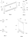
FIG. 1 is an exploded perspective view of a fixture according to the present invention. -
FIG. 2 is an assembled view ofFIG. 1 . -
FIG. 3 is an assembled view ofFIG. 2 viewed from another angle. -
FIG. 4 is a perspective view of a support block ofFIG. 1 . -
FIG. 5 is a plan view of a thermal conductive plate ofFIG. 1 viewed from a length direction. -
FIG. 6 is a perspective view ofFIG. 5 . -
FIG. 7 is a plan view of two thermal conductive plates ofFIG. 1 mating together viewed from the length direction. -
FIG. 8 is a perspective view ofFIG. 7 . -
FIG. 9 is an enlarged view of a circle part inFIG. 8 . -
FIG. 10 is an enlarged view of another circle part inFIG. 8 . -
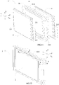
FIG. 11 is an exploded perspective view of a battery unit according to the present invention, in which electrode tabs are not bent. -
FIG. 12 is an assembled view ofFIG. 11 in which the electrode tabs have been bent, and the electrode tabs may be bent when the battery unit is formed or may not be bent when the battery unit is formed but may be bent when the battery module is formed. -
FIG. 13 is a perspective view taken along an A-A line inFIG. 12 . -
FIG. 14 is a perspective view taken along a B-B line inFIG. 12 . -
FIG. 15 is an exploded perspective view of a battery module according to the present invention. -
FIG. 16 is an assembled view of a part of components ofFIG. 15 . -
FIG. 17 is an assembled view ofFIG. 15 . -
FIG. 18 is a perspective view taken along a C-C line inFIG. 17 . - Reference numerals are represented as follows:
- M battery module
- 1 thermal conductive frame
- 11 peripheral wall
- 111 recessed portion
- 112 end surface
- 12 receiving cavity
- 2 battery unit
- 21 pouch-shaped secondary battery
- 211 main body
- 212 electrode tab
- 22 fixture
- 221 thermal conductive plate
- S1 receiving space
- S2 hollow cavity
- S3 middle space
- 2211 abutting portion
- 2212 contact portion
- 2213 connecting portion
- C1 bending section
- C2 connection section
- C3 abutting section
- C4 inclined section
- 222 support block
- 2221 recessed groove
- 2222 receiving groove
- 2223 through hole
- 2224 positioning groove
- L length direction
- T thickness direction
- H height direction
- 3 connecting piece
- 31 upright portion
- 4 output piece
- 41 protrusion
- 5 elastic buffering pad
- 6 end plate
- 61 plate body
- 611 positioning protrusion
- 612 inner surface
- 62 insert
- 621 protruding portion
- Hereinafter a fixture, a battery unit and a battery module of the present invention will be described in detail in combination with the figures.
- Firstly, a fixture according to a first aspect of the present invention will be described.
- As shown in
FIG. 1 to FIG. 10 , afixture 22 of the first aspect of the present invention comprises at least one thermalconductive plate 221 and two support blocks 222. Each thermalconductive plate 221 comprises: an abuttingportion 2211 extending along a height direction H; acontact portion 2212 positioned at a side of the abuttingportion 2211 in the height direction H and extending toward a thickness direction T of the thermalconductive plate 221; and a connectingportion 2213 connecting the abuttingportion 2211 and thecontact portion 2212 along the height direction H. The twosupport blocks 222 are respectively fixed on two ends of the at least one thermalconductive plate 221 in a length direction L; the abuttingportion 2211, the connectingportion 2213 and thecontact portion 2212 of each thermalconductive plate 221 and the twosupport blocks 222 form a receiving space S1 having an opening opened away from the abuttingportion 2211. - In the
fixture 22 according to the first aspect of the present invention, when thefixture 22 of the first aspect of the present invention is applied to abattery unit 2 and a battery module M described below, compared with the structure using the traditional aluminum plates or the plastics which are latched with each other in the front-rear direction in the prior art, the abuttingportion 2211 of each thermalconductive plate 221 is attached onto themain body 211 of the pouch-shapedsecondary battery 21 described below along the thickness direction T, heat generated by the pouch-shapedsecondary battery 21 can be transferred to the abuttingportion 2211 of the thermalconductive plate 221 attached onto the pouch-shapedsecondary battery 21, and then transferred outwardly (such as to the thermalconductive frame 1 described below) via thecontact portion 2212 so as to improve the heat dissipation effect of the battery module M; eachfixture 22 uses the twosupport blocks 222 and the at least one pouch-shapedsecondary battery 21 to form abattery unit 2, which makes the assembling of the plurality ofbattery units 2 simple, and reduces the number of assembled components, improves the assembling efficiency of the battery module M and reduces the costs. - As shown in
FIG. 1 to FIG. 9 , the connectingportion 2213 of each thermalconductive plate 221 is formed with a bending section C1 formed as a V-shape (of course it is not limited to this, but also can be other shapes, such as circular-arc) and extending along the length direction L of each thermalconductive plate 221, a bending corner of the bending section C1 protrudes toward the opening of the receiving space S1. When the battery module M described below is subjected to external mechanical vibration, because a connecting corner between thecontact portion 2212 and the connectingportion 2213 of the thermalconductive plate 221 is easily broken due to concentrated stress, the design of the bending section C1 functions as buffering stress at the connecting corner between thecontact portion 2212 and the connectingportion 2213, which avoids the stress concentration at the connecting corner and effectively improves the strength of the heat-conductive plate 221, avoids damage to the connecting corner of the heat-conductive plate 221 due to the external mechanical vibration, and lengthen the service life of the battery module M. In addition, the bending section C1 increases the heat dissipation area and the heat dissipation effect and effectively utilizes the space of the battery unit 2 (described below) above themain body 211 of the pouch-shapedsecondary battery 21 in the height direction H. - In the
fixture 22 according to the first aspect of the present invention, preferably, the thermalconductive plate 221 is provided as two in number, the two thermalconductive plates 221 abut together along the thickness direction T of thefixture 22; the bending sections C1 of the two thermalconductive plates 221 are opposed to each other and enclose a hollow cavity S2. The two thermalconductive plates 221 abut together along the thickness direction T of thefixture 22, which allows the heat of the two thermalconductive plates 221 to be coupled together, improves the heat dissipation effect of themain bodies 211 of the two pouch-shapedsecondary batteries 21 of thebattery unit 2 described below, and improves the uniformity of the temperature of the two pouch-shapedsecondary batteries 21. The hollow cavity S2 can alleviate the damage from the external mechanical vibration to the connecting corner of the heat-conductive plate 221, and improves the strength of the heat-conductive plate 221. - Referring to
FIG. 1 andFIG. 5 toFIG. 9 , the connectingportion 2213 of each thermalconductive plate 221 is further formed with a connection section C2 connecting one end of the bending section C1 in the height direction H and thecontact portion 2212. - Specifically, as shown in
FIG. 8 , the thermalconductive plate 221 is provided as two in number; the two connection sections C2 of the two thermalconductive plates 221 abut together along the thickness direction T of thefixture 22. Similarly, the two connection sections C2 of the two thermalconductive plates 221 abut together along the thickness direction T of thefixture 22, which allows the heat of the two thermalconductive plates 221 to be coupled together, and improves the heat dissipation effect of themain bodies 211 of the two pouch-shapedsecondary batteries 21 of thebattery unit 2 described below, and improves the uniformity of the temperature of the two pouch-shapedsecondary batteries 21. - As shown in
FIG. 9 , the connectingportion 2213 of each thermalconductive plate 221 is further formed with: an abutting section C3 extending along the height direction H, one end of the abutting section C3 in the height direction H connects with the other end of the bending section C1 in the height direction H; and an inclined section C4 connecting the abutting section C3 and the abuttingportion 2211, inclining from the abutting section C3 toward the abuttingportion 2211 so that the abuttingportion 2211 is close to the opening of the receiving space S1 relative to the abutting section C3. - In the
fixture 22 according to the first aspect of the present invention, as shown inFIG. 1 to FIG. 3 andFIG. 7 to FIG. 10 , the thermalconductive plate 221 is provided as two in number; the two abutting sections C3 of the two thermalconductive plates 221 abut together along the thickness direction T of thefixture 22; the inclined section C4 and the abuttingportion 2211 of one thermalconductive plate 221 and the inclined section C4 and the abuttingportion 2211 of the other thermalconductive plate 221 are spaced apart from each other to form a middle space S3. Similarly, the two abutting sections C3 of the two thermalconductive plates 221 abut together along the thickness direction T of thefixture 22, which allows the heat of the two thermalconductive plates 221 to be coupled together, and improves the heat dissipation effect of themain body 211 of the two pouch-shapedsecondary batteries 21 of thebattery unit 2 described below and improves the uniformity of the temperature of the two pouch-shapedsecondary batteries 21. The formation of the middle space S3 provides sufficient expansion spaces for the pouch-shapedsecondary batteries 21 described below. - As shown in
FIG. 1 to FIG. 4 , an end of eachsupport block 222 in the height direction H is provided with a recessedgroove 2221; an end portion of thecontact portion 2212 of each thermalconductive plate 221 in the length direction L is received in the recessedgroove 2221. The recessedgroove 2221 functions as positioning and supporting thecontact portion 2212, and functions as transferring an external force, which is transferred to thecontact portion 2212 via the thermalconductive frame 1 when the battery module M is subjected to external impact and/or vibration, to thesupport block 222 and allows thesupport block 222 to disperse the external force. - In the
fixture 22 according to the first aspect of present invention, there are many ways to arrange thecontact portion 2212 and the connectingportion 2213 of each thermalconductive plate 221. For example, thecontact portion 2212 and the connectingportion 2213 may be provided only at one side of the heat-conductive plate 221; in order to improve the heat transfer efficiency, preferably, thecontact portion 2212 and the connectingportion 2213 of each thermalconductive plate 221 are both provided as two in number, and the twocontact portions 2212 of each thermalconductive plate 221 are respectively positioned at two sides of the abuttingportion 2211 in the height direction H and the two connectingportions 2213 of each thermalconductive plate 221 are respectively positioned at the two sides of the abuttingportion 2211 in the height direction H, and thus achieves conducting heat at the two sides in the height direction H. The heat dissipation effect with conducting heat at the two sides in the height direction H is much higher than the heat dissipation effect with conducting heat on the bottom (i.e., conducting heat at one side) in the background technique. The abuttingportion 2211 of the heat-conductive plate 212 is a flat plate, so that the abuttingportion 2211 can sufficiently contact the relatively flat surface of themain body 211 of the pouch-shapedsecondary battery 21 of the described belowbattery unit 2 and conduct heat. - As shown in
FIG. 1 to FIG. 10 , preferably, shapes of the two thermalconductive plates 221 are the same, and the two thermalconductive plates 221 are mirror symmetrically mated together along the thickness direction T of thefixture 22. Therefore the thermalconductive plate 221 is not only easy to manufacture but also easy to assemble. - As shown in
FIG. 1 andFIG. 4 , eachsupport block 222 is provided with a receivinggroove 2222, an end of each thermalconductive plate 221 in the length direction L is fixed in the receivinggroove 2222 of thesupport block 222. - Each
support block 222 is plastic. Each thermalconductive plate 221 is aluminum plate. Each thermalconductive plate 221 is formed by stamping. - The two
support blocks 222 are integrally formed with the at least one thermalconductive plate 221. Of course, the formation method is not limited to this, and other formation method may be used, for example, eachsupport block 222 and each thermalconductive plate 221 are formed separately and then the twosupport blocks 222 and the at least one thermalconductive plate 221 are fixed together by assembling. - A side of the receiving
groove 2222 of eachsupport block 222 is further provided with a throughhole 2223 passing through eachsupport block 222. - Each
support block 222 is further provided with at least onepositioning groove 2224 positioned on an outer side surface of thesupport block 222 in the length direction L. - In the
fixture 22 according to the first aspect of the present invention, it should be noted that, when thefixture 22 is applied to thebattery unit 2 described below and before thebattery unit 2 is assembled, that is, thebattery unit 2 described below is not mounted into the thermalconductive frame 1, thecontact portion 2212 and the connectingportion 2213 of the thermalconductive plate 221 are perpendicular to each other (as shown inFIG. 1 to FIG. 9 ), of course, it is not limited to this, in another embodiment, thecontact portion 2212 of each thermalconductive plate 221 inclines (such as 3-10 degrees) toward an outer side in the height direction H with respect to an outer surface of eachsupport block 222 in the height direction H, so that an edge of thecontact portion 2212 in the thickness direction protrudes in the height direction H relative to the outer surface of eachsupport block 222 in the height direction H. When eachbattery unit 2 is mounted into the thermalconductive frame 1 described below, thecontact portion 2212 of each thermalconductive plate 221 is squeezed by the thermalconductive frame 1, thecontact portion 2212 elastically deforms and abuts toward eachsupport block 222. Therefore, it effectively ensures the effective contact and the heat conduction area between thecontact portion 2212 and an inner surface of the thermalconductive frame 1. - Secondly, a battery unit according to a second aspect of the present invention will be described.
- As shown in
FIG. 1 to FIG. 14 , abattery unit 2 according to a second aspect of the present invention comprises at least one pouch-shapedsecondary battery 21, each pouch-shapedsecondary battery 21 comprises amain body 211, thebattery unit 2 further comprises thefixture 22 according to the first aspect of the present invention; each pouch-shapedsecondary battery 21 is fixed in one receiving space S1 of thefixture 22; the abuttingportion 2211 of each thermalconductive plate 221 is attached to themain body 211 of each pouch-shapedsecondary battery 21 along the thickness direction T (referring toFIG. 14 ). - In the
battery unit 2 according to the second aspect of the present invention, attaching the abuttingportion 2211 of each thermalconductive plate 221 to themain body 211 of the pouch-shapedsecondary battery 21 along the thickness direction T, heat generated by the pouch-shapedsecondary battery 21 can be transferred to the abuttingportion 2211 of the thermalconductive plate 221 which is attached to themain body 211 of the pouch-shapedsecondary battery 21 and the heat can be transferred outwardly via thecontact portion 2212, eachfixture 22 uses the twosupport blocks 222 and the at least one pouch-shapedsecondary battery 21 to form abattery unit 2, which makes the assembling of the plurality ofbattery units 2 easily, reduces the number of assembled components, improves the assembling efficiency of the battery module M, and reduces the costs. - As shown in
FIG. 11 and FIG. 12 , each pouch-shapedsecondary battery 21 comprises twoelectrode tabs 212 extending outwardly from two ends of themain body 211 in the length direction L respectively; the side of the receivinggroove 2222 of eachsupport block 222 is further provided with a throughhole 2223 passing through eachsupport block 222; eachelectrode tab 212 respectively passes through the corresponding throughhole 2223 of thesupport block 222. In an alternative embodiment, the pouch-shapedsecondary battery 21 comprises twoelectrode tabs 212 extending outwardly from one end of themain body 211 in the length direction L. - The
main body 211 of each pouch-shapedsecondary battery 21 is adhered and fixed to the abuttingportion 2211 of the corresponding thermalconductive plate 221 of thefixture 22. In thebattery unit 2 according to the second aspect of the present invention, referring toFIG. 12 , preferably, when two pouch-shapedsecondary batteries 21 are fixed in thefixture 22, theelectrode tabs 212 of the two pouch-shapedsecondary batteries 21 at one end of the length direction L bend oppositely and are attached together. - Next, a battery module according to a third aspect of the present invention will be described.
- As shown in
FIG. 15 to FIG. 17 , a battery module M according to a third aspect of the present invention comprises a thermalconductive frame 1. The thermalconductive frame 1 has aperipheral wall 11 and a receivingcavity 112 enclosed by theperipheral wall 11, the receivingcavity 112 is closed in a circumferential direction and is opened at two ends in a length direction L; the battery module M further comprises a plurality ofbattery units 2 according to the second aspect of the present invention, the plurality ofbattery units 2 are arranged side by side and received in the receivingcavity 12, and thecontact portion 2212 of each thermalconductive plate 221 contact theperipheral wall 11 of the thermalconductive frame 1. - In the battery module M according to the third aspect of the present invention, the
contact portion 2212 of each thermalconductive plate 221 contacts theperipheral wall 11 of the thermalconductive frame 1, the thermalconductive frame 1 enclosed by theperipheral wall 11 and closed in circumference direction can use the wholeperipheral wall 11 to dissipate heat, thereby improving the heat dissipation effect of the battery module M; the thermalconductive frame 1 enclosed by theperipheral wall 11 and closed in the circumference direction also can restrain the expansion generated by the pouch-shapedsecondary batteries 21 during the charge-discharge cycle, so as to ensure the stability of the outer shape of the battery module M; eachfixture 22 uses the twosupport blocks 222 and the at least one pouch-shapedsecondary battery 21 to form abattery unit 2, which makes the assembling of the plurality ofbattery units 2 easily, reduces the number of assembled components, improves the assembling efficiency of the battery module M, and reduces the costs. When an external cooling system is used, the external cooling system is provided below the bottom of theperipheral wall 11, while the other part of theperipheral wall 11 will still conduct heat toward the external cooling system, thereby increasing the thermal connection with the external cooling system and improving the heat dissipation effect. In addition, the other part of theperipheral wall 11 can also be cooled by air so as to enhance the flexibility of the heat dissipation way. - As shown in
FIG. 15 and FIG. 16 , when the two pouch-shapedsecondary batteries 21 are fixed in thefixture 22, theelectrode tabs 212 of the two pouch-shapedsecondary batteries 21 at one end in the length direction L are bent oppositely and are attached to each other ; the battery module M further comprises: a plurality of connectingpieces 3 for connecting the plurality of pouch-shapedsecondary batteries 21 together, each connectingpiece 3 has twoupright portions 31, eachupright portions 31 electrically connects with theelectrode tabs 212, which are bent oppositely and attached to each other, of the pouch-shapedsecondary batteries 21 of each of twoadjacent battery units 2; twooutput pieces 4 for outputs of the plurality of pouch-shapedsecondary batteries 21, and eachoutput piece 4 electrically connects with theelectrode tabs 212, which are bent oppositely and attached to each other, of the pouch-shapedsecondary batteries 21 of each of twobattery units 2 respectively adjacent to the twooutput pieces 4. - In the battery module M according to the third aspect of the present invention, it should be noted that, before assembling, that is, the
battery unit 2 is not mounted into the thermalconductive frame 1, thecontact portion 2212 and the connectingportion 2213 of the thermalconductive plate 221 are perpendicular to each other (as shown inFIG. 11 to FIG. 14 ), of course, it is not limited to this, in another embodiment, when eachbattery unit 2 is not mounted into the thermalconductive frame 1, thecontact portion 2212 of each thermalconductive plate 221 inclines (such as 3-10 degrees) toward an outer side in the height direction H with respect to an outer surface of thesupport block 222 in the height direction H, so that an edge of thecontact portion 2212 in the thickness direction T protrudes in the height direction H relative to the outer surface of each support blocks 222 in the height direction H. When eachbattery unit 2 is mounted into the thermalconductive frame 1, thecontact portion 2212 of each thermalconductive plate 221 is squeezed by the thermalconductive frame 1, thecontact portion 2212 elastically deforms and abuts toward eachsupport block 222. Therefore, it effectively ensures the effective contact between thecontact portion 2212 and an inner surface of the thermalconductive frame 1 and further ensures the heat conduction area. Preferably, the attachment eventually makes thecontact portion 2212 become a flattened state as shown inFIG. 11 to FIG. 14 . - In the battery module M according to the third aspect of the present invention, as shown in
FIG. 15 , the battery module M further comprises a plurality ofelastic buffering pads 5 respectively provided between every twoadjacent battery units 2 and between twobattery units 2 positioned at outermost sides of an arrangement direction and the thermalconductive frame 1. Theelastic buffering pads 5 allow the plurality ofbattery units 2 to be easily assembled into the thermalconductive frame 1 after compression deformation, while after the plurality ofbattery units 2 are assembled into the thermalconductive frame 1, theelastic buffering pads 5 elastically recover, so that theelastic buffering pads 5 together with the thermalconductive frame 1 can firmly position and clamp the plurality ofbattery units 2, which ensures the structural stability of thebattery units 2 and functions as buffering and can effectively ensure the stability of the heat dissipation path when the battery module M is subjected to external impact and/or vibration; in addition, the elastic deformation characteristics of theelastic buffering pads 5 can provide an expansion space for the expansion of the pouch-shaped secondary batteries during the charge-discharge cycle. Theelastic buffering pad 5 may be a foam. - As shown in
FIG. 15 and FIG. 16 , the battery module M further comprises twoend plates 6 respectively fixed to two ends of the opening of the thermalconductive frame 1 in the length direction L. Eachoutput piece 4 comprises aprotrusion 41 protruding outwardly along the length direction L; theprotrusions 41 of the twooutput pieces 4 pass through and are sealed to one of the twoend plates 6. - Referring to
FIG. 15 to FIG. 17 , eachend plate 6 comprises: aplate body 61, aninner surface 612 of a periphery of theplate body 61 in the length direction L abuts anend surface 112 of theperipheral wall 11 of the thermalconductive frame 1 at one end in the length direction L; and aninsert 62 securely provided on theplate body 61. - Each
support block 222 is further provided with at least onepositioning groove 2224 positioned at an outer side surface of eachsupport block 222 in the length direction L; theplate body 61 is provided with at least onepositioning protrusion 611 positioned at a side of theplate body 61 facing eachsupport block 222; eachpositioning protrusion 611 is inserted into onepositioning groove 2224. The design of thepositioning groove 2224 and thepositioning protrusion 611 allows theend plates 6 and the support blocks 222 of the plurality ofbattery units 2 to be positioned together, such a positioning manner will not form stress concentration point at the welding location between the battery module M and theend plates 6 described below in the process of mechanical vibration (that is, the external force is transferred to theplate body 61 via thepositioning protrusion 611 and then transferred to the thermalconductive frame 1, so that the external force is dispersed). Of course, the positioning method is not limited to this, and other forms can be used to position. - As shown in
FIG. 15 to FIG. 18 , two ends of theperipheral wall 11 of the thermalconductive frame 1 in the length direction L are provided with recessedportions 111; eachinsert 62 comprises protrudingportions 621 protruding along the length direction L respectively at a left side and a right side, each protrudingportion 621 engages with each recessedportion 111. The edge of each protrudingportion 621 and each recessedportion 111 of theperipheral wall 11 of the thermalconductive frame 1 may be welded together. - A material of the
plate body 61 is plastic, and a material of theinsert 62 is aluminum. Theplate body 61 is integrated with theinsert 62 by injection molding. - A material of the thermal
conductive frame 1 is aluminum. - Finally, as an example, an assembling method of the battery module M according the third aspect of the present invention will be described.
- An assembling method of the battery module M according the third aspect of the present invention comprises steps of: providing a plurality of
elastic buffering pads 5 between every twoadjacent battery units 2 and the outer surfaces of twobattery units 2 positioned at the outermost sides of the arrangement direction to form a group; clamping the group with a fixture tool and mounted the group into the receivingcavity 12 of the thermalconductive frame 11; welding theoutput pieces 4 and the connectingpieces 3 to theelectrode tabs 212 of the pouch-shapedsecondary batteries 21; assembling the twoend plates 6 and fixing the twoend plates 6 to the ends of the thermalconductive frame 1 in the axial direction.
Claims (15)
- A fixture (22), comprising:at least one thermal conductive plate (221), each thermal conductive plate (221) comprising:an abutting portion (2211) extending along a height direction (H); anda contact portion (2212) positioned at a side of the abutting portion (2211) in the height direction (H) and extending toward a thickness direction (T) of the thermal conductive plate (221); anda connecting portion (2213) connecting the abutting portion (2211) and the contact portion (2212) along the height direction (H); andtwo support blocks (222) respectively fixed on two ends of the at least one thermal conductive plate (221) in a length direction (L);the abutting portion (2211), the connecting portion (2213) and the contact portion (2212) of each thermal conductive plate (221) and the two support blocks (222) forming a receiving space (S1) having an opening opened away from the abutting portion (2211).
- The fixture (22) according to Claim 1, wherein
the connecting portion (2213) of each thermal conductive plate (221) is formed with a bending section (C1) formed as a V-shape and extending along the length direction (L) of each thermal conductive plate (221), a bending corner of the bending section (C1) protrudes toward the opening of the receiving space (S1). - The fixture (22) according to Claim 2, wherein
the thermal conductive plate (221) is provided as two in number, the two thermal conductive plates (221) abut together along the thickness direction (T) of the fixture (22);
the bending sections (C1) of the two thermal conductive plates (221) are opposed to each other and enclose a hollow cavity (S2). - The fixture (22) according to Claim 2, wherein the connecting portion (2213) of each thermal conductive plate (221) is further formed with a connection section (C2) connecting one end of the bending section (C1) in the height direction (H) and the contact portion (2212).
- The fixture (22) according to Claim 4, wherein
the thermal conductive plate (221) is provided as two in number;
the two connection sections (C2) of the two thermal conductive plates (221) abut together along the thickness direction (T) of the fixture (22). - The fixture (22) according to Claim 4, wherein the connecting portion (2213) of each thermal conductive plate (221) is further formed with:an abutting section (C3) extending along the height direction (H), one end of the abutting section (C3) in the height direction (H) connects with the other end of the bending section (C1) in the height direction (H); andan inclined section (C4) connecting the abutting section (C3) and the abutting portion (2211), inclining from the abutting section (C3) toward the abutting portion (2211) so that the abutting portion (2211) is close to the opening of the receiving space (S1) relative to the abutting section (C3).
- The fixture (22) according to Claim 6, wherein
the thermal conductive plate (221) is provided as two in number;
the two abutting sections (C3) of the two thermal conductive plates (221) abut together along the thickness direction (T) of the fixture (22);
the inclined section (C4) and the abutting portion (2211) of one thermal conductive plate (221) and the inclined section (C4) and the abutting portion (2211) of the other thermal conductive plate (221) are spaced apart from each other to form a middle space (S3). - The fixture (22) according to Claim 1, wherein the contact portion (2212) of each thermal conductive plate (221) inclines toward an outer side in the height direction (H) with respect to an outer surface of each support block (222) in the height direction (H), so that an edge of the contact portion (2212) in the thickness direction (T) protrudes in the height direction (H) relative to the outer surface of each support block (222) in the height direction (H).
- A battery unit (2), comprising at least one pouch-shaped secondary battery (21), each pouch-shaped secondary battery (21) comprising a main body (211), wherein the battery unit (2) further comprises the fixture (22) according to any one of Claims 1-7, each pouch-shaped secondary battery (21) is fixed in one receiving space (S1) of the fixture (22), the abutting portion (2211) of each thermal conductive plate (221) is attached to the main body (211) of each pouch-shaped secondary battery (21) along the thickness direction (T).
- A battery module (M), comprising:a thermal conductive frame (1), having:a peripheral wall (11); anda receiving cavity (112) enclosed by the peripheral wall (11), the receiving cavity (112) being closed in a circumferential direction and being opened at two ends in a length direction (L);wherein the battery module (M) further comprises a plurality of battery units (2) according to Claim 9, the plurality of battery units (2) are arranged side by side and are received in the receiving cavity (12), and the contact portion (2212) of each thermal conductive plate (221) contact the peripheral wall (11) of the thermal conductive frame (1).
- The battery module (M) according to Claim 10, wherein
when each battery unit (2) is not mounted into the thermal conductive frame (1), the contact portion (2212) of each thermal conductive plate (221) inclines toward an outer side in the height direction (H) with respect to an outer surface of each support blocks (222) in the height direction (H), so that an edge of the contact portion (2212) in the thickness direction (T) protrudes in the thickness direction (T) relative to the outer surface of each support block (222) in the height direction (H);
when each battery unit (2) is mounted into the thermal conductive frame (1), the contact portion (2212) of each thermal conductive plate (221) is squeezed by the thermal conductive frame (1), the contact portion (2212) elastically deforms and abuts toward each support block (222). - The battery module (M) according to Claim 10, wherein the battery module (M) further comprises a plurality of elastic buffering pads (5) respectively provided between every two adjacent battery units (2) and between two battery units (2) positioned at outermost sides of an arrangement direction and the thermal conductive frame (1).
- The battery module (M) according to Claim 10, wherein
the battery module (M) further comprises two end plates (6) respectively fixed to two ends of the opening of the thermal conductive frame (1) in the length direction (L). - The battery module (M) according to Claim 13, wherein each end plate (6) comprises:a plate body (61), an inner surface (612) at a periphery of the plate body (61) in the length direction (L) abuts an end surface (112) of the peripheral wall (11) of the thermal conductive frame (1) at one end in the length direction (L); andan insert (62) securely provided on the plate body (61).
- The battery module (M) according to Claim 14, wherein
each support block (222) is further provided with at least one positioning groove (2224) positioned at an outer side surface of each support block (222) in the length direction (L);
the plate body (61) is provided with at least one positioning protrusion (611) positioned at a side of the plate body (61) facing each support block (222);
each positioning protrusion (611) is inserted into one positioning groove (2224).
Applications Claiming Priority (1)
| Application Number | Priority Date | Filing Date | Title |
|---|---|---|---|
| CN201710770732.2A CN109428023B (en) | 2017-08-31 | 2017-08-31 | Fixing frame, battery unit and battery module |
Publications (2)
| Publication Number | Publication Date |
|---|---|
| EP3451413A1 true EP3451413A1 (en) | 2019-03-06 |
| EP3451413B1 EP3451413B1 (en) | 2023-11-08 |
Family
ID=63113443
Family Applications (1)
| Application Number | Title | Priority Date | Filing Date |
|---|---|---|---|
| EP18186816.7A Active EP3451413B1 (en) | 2017-08-31 | 2018-08-01 | Fixture, battery unit and battery module |
Country Status (3)
| Country | Link |
|---|---|
| US (1) | US10811742B2 (en) |
| EP (1) | EP3451413B1 (en) |
| CN (1) | CN109428023B (en) |
Cited By (1)
| Publication number | Priority date | Publication date | Assignee | Title |
|---|---|---|---|---|
| EP3886241A1 (en) * | 2020-03-27 | 2021-09-29 | China Lithium Battery Technology Co., Limited | Pouch battery module |
Families Citing this family (16)
| Publication number | Priority date | Publication date | Assignee | Title |
|---|---|---|---|---|
| KR102378527B1 (en) * | 2018-12-05 | 2022-03-23 | 주식회사 엘지에너지솔루션 | Battery module and the method of manufacturing the same |
| CN113678310B (en) * | 2019-03-29 | 2024-03-26 | 株式会社村田制作所 | Battery pack |
| CN110190223A (en) * | 2019-05-20 | 2019-08-30 | 广州中国科学院工业技术研究院 | Prospect of EVS Powered with Batteries mould group |
| CN112103419B (en) * | 2019-06-18 | 2024-09-06 | 宁德时代新能源科技股份有限公司 | Temperature control components and battery pack |
| JP7267129B2 (en) * | 2019-07-10 | 2023-05-01 | 本田技研工業株式会社 | storage module |
| KR102418265B1 (en) * | 2019-08-08 | 2022-07-07 | 주식회사 엘지에너지솔루션 | Battery Pack Comprising Heating Member |
| CN110518164B (en) * | 2019-08-22 | 2024-09-24 | 宿州市艾尔新能源有限公司 | Battery tray with heat radiation structure |
| CN110854330A (en) * | 2019-11-27 | 2020-02-28 | 华霆(合肥)动力技术有限公司 | Exhaust positioning tool, battery module and battery pack |
| CN112103428B (en) * | 2020-09-09 | 2022-10-25 | 湖州快驴科技有限公司 | Fixed knot that soft-packaged electric core utmost point ear fracture of prevention constructs |
| CN112670658B (en) * | 2020-12-30 | 2025-10-14 | 珠海格力钛电器有限公司 | battery pack |
| KR102945306B1 (en) * | 2021-02-22 | 2026-03-30 | 에스케이온 주식회사 | Battery cell assembly and battery pack having thereof |
| CN114725601B (en) * | 2022-03-24 | 2023-09-01 | 福州福享汽车工业有限公司 | Tilting energy storage battery cabinet with anti-falling function |
| CN119678300A (en) * | 2023-03-31 | 2025-03-21 | 厦门新能达科技有限公司 | Battery modules and electrical equipment |
| CN117059949B (en) * | 2023-08-08 | 2024-03-19 | 苏州星羽翔电子科技有限公司 | Battery module, battery pack, and method for manufacturing battery module |
| DE102024003368A1 (en) | 2024-10-16 | 2026-04-16 | Mercedes-Benz Group AG | Cell holder, battery module, method for mounting the battery module and vehicle |
| DE102024003378A1 (en) | 2024-10-16 | 2026-04-16 | Mercedes-Benz Group AG | Cell holder, battery module and vehicle |
Citations (5)
| Publication number | Priority date | Publication date | Assignee | Title |
|---|---|---|---|---|
| EP2366200A1 (en) * | 2008-12-12 | 2011-09-21 | LG Chem, Ltd. | Battery module having excellent heat dissipation ability and battery pack employed with the same |
| US20150010801A1 (en) * | 2013-07-08 | 2015-01-08 | Lg Chem, Ltd. | Battery assembly |
| US20150086832A1 (en) * | 2013-09-24 | 2015-03-26 | Microvast Power Systems Co., Ltd. | Battery pack injected with phase change material |
| US20150221996A1 (en) * | 2012-08-30 | 2015-08-06 | Sk Innovation Co., Ltd. | Battery Module |
| US20170187082A1 (en) * | 2014-11-10 | 2017-06-29 | SZ DJI Technology Co., Ltd. | Battery and thermal management device thereof, and uav having the battery |
Family Cites Families (10)
| Publication number | Priority date | Publication date | Assignee | Title |
|---|---|---|---|---|
| JP3485162B2 (en) * | 1998-10-09 | 2004-01-13 | 矢崎総業株式会社 | Battery connection plate and method of manufacturing the same |
| DE102009058808A1 (en) * | 2009-12-18 | 2011-06-22 | Valeo Klimasysteme GmbH, 96476 | Cooling device for a vehicle drive battery and vehicle drive battery assembly with cooling device |
| TWI426637B (en) * | 2011-01-12 | 2014-02-11 | Delta Electronics Inc | Battery module |
| CN107946689B (en) * | 2011-04-15 | 2021-01-22 | Cps科技控股有限公司 | Battery system with external thermal management system |
| JP5513445B2 (en) * | 2011-06-08 | 2014-06-04 | 本田技研工業株式会社 | Vehicle power supply |
| US8336538B2 (en) * | 2011-07-21 | 2012-12-25 | Peguero Fernando A | Solar heat collector module |
| US9331312B2 (en) * | 2011-10-12 | 2016-05-03 | Samsung Sdi Co., Ltd. | Secondary battery |
| CN103904254B (en) * | 2014-02-25 | 2017-01-18 | 江苏华东锂电技术研究院有限公司 | Battery module |
| CN105895994A (en) * | 2016-06-15 | 2016-08-24 | 北京海博思创科技有限公司 | Heat-conducting device and battery module |
| CN209658243U (en) * | 2019-04-09 | 2019-11-19 | 宁德时代新能源科技股份有限公司 | Secondary cell cap assembly and secondary cell |
-
2017
- 2017-08-31 CN CN201710770732.2A patent/CN109428023B/en active Active
-
2018
- 2018-07-31 US US16/051,239 patent/US10811742B2/en active Active
- 2018-08-01 EP EP18186816.7A patent/EP3451413B1/en active Active
Patent Citations (5)
| Publication number | Priority date | Publication date | Assignee | Title |
|---|---|---|---|---|
| EP2366200A1 (en) * | 2008-12-12 | 2011-09-21 | LG Chem, Ltd. | Battery module having excellent heat dissipation ability and battery pack employed with the same |
| US20150221996A1 (en) * | 2012-08-30 | 2015-08-06 | Sk Innovation Co., Ltd. | Battery Module |
| US20150010801A1 (en) * | 2013-07-08 | 2015-01-08 | Lg Chem, Ltd. | Battery assembly |
| US20150086832A1 (en) * | 2013-09-24 | 2015-03-26 | Microvast Power Systems Co., Ltd. | Battery pack injected with phase change material |
| US20170187082A1 (en) * | 2014-11-10 | 2017-06-29 | SZ DJI Technology Co., Ltd. | Battery and thermal management device thereof, and uav having the battery |
Cited By (2)
| Publication number | Priority date | Publication date | Assignee | Title |
|---|---|---|---|---|
| EP3886241A1 (en) * | 2020-03-27 | 2021-09-29 | China Lithium Battery Technology Co., Limited | Pouch battery module |
| US11502365B2 (en) | 2020-03-27 | 2022-11-15 | Calb Co., Ltd. | Pouch battery module |
Also Published As
| Publication number | Publication date |
|---|---|
| US10811742B2 (en) | 2020-10-20 |
| EP3451413B1 (en) | 2023-11-08 |
| CN109428023B (en) | 2024-04-16 |
| US20190067762A1 (en) | 2019-02-28 |
| CN109428023A (en) | 2019-03-05 |
Similar Documents
| Publication | Publication Date | Title |
|---|---|---|
| EP3451413B1 (en) | Fixture, battery unit and battery module | |
| US10818896B2 (en) | Frame and battery module | |
| JP6001547B2 (en) | Battery module with enhanced safety | |
| JP6083824B2 (en) | Battery cell holder with improved connection reliability and battery module including the same | |
| CN103238250B (en) | Cooling units and vehicle battery components | |
| CN106663760A (en) | Power source device | |
| JP7082661B2 (en) | Rechargeable battery pack with heat dissipation plate | |
| US11515592B2 (en) | Battery module | |
| CN104380497B (en) | Energy storage module including multiple energy storage components and improved heat dissipation device and assemble method | |
| US20190006643A1 (en) | Battery module | |
| EP3654401B1 (en) | Side plate and battery module | |
| JP2019046578A (en) | Method of manufacturing battery pack | |
| CN112234284B (en) | Battery cell mounting rack, battery module, battery pack and vehicle | |
| WO2015186501A1 (en) | Battery module and battery pack | |
| CN100521363C (en) | Battery module with improved cell barrier between unit cells | |
| CN101983443A (en) | Medium-sized and large-sized battery modules having electrode terminal connection member and insulating joint member | |
| JP2017103158A (en) | Battery pack | |
| JP6647991B2 (en) | Power converter | |
| CN207116550U (en) | Fixed mount, battery unit and battery modules | |
| CN119790532A (en) | Electrochemical devices and electrical equipment | |
| KR20230120578A (en) | Battery module | |
| EP3373360B1 (en) | Battery module | |
| KR20190061390A (en) | Battery pack with asymmetric arrangement | |
| CN207116553U (en) | Fixed mount, battery unit and battery modules | |
| CN109428025B (en) | Fixing frame, battery unit and battery module |
Legal Events
| Date | Code | Title | Description |
|---|---|---|---|
| PUAI | Public reference made under article 153(3) epc to a published international application that has entered the european phase |
Free format text: ORIGINAL CODE: 0009012 |
|
| STAA | Information on the status of an ep patent application or granted ep patent |
Free format text: STATUS: REQUEST FOR EXAMINATION WAS MADE |
|
| 17P | Request for examination filed |
Effective date: 20180801 |
|
| AK | Designated contracting states |
Kind code of ref document: A1 Designated state(s): AL AT BE BG CH CY CZ DE DK EE ES FI FR GB GR HR HU IE IS IT LI LT LU LV MC MK MT NL NO PL PT RO RS SE SI SK SM TR |
|
| AX | Request for extension of the european patent |
Extension state: BA ME |
|
| STAA | Information on the status of an ep patent application or granted ep patent |
Free format text: STATUS: EXAMINATION IS IN PROGRESS |
|
| 17Q | First examination report despatched |
Effective date: 20210209 |
|
| REG | Reference to a national code |
Ref country code: DE Ref legal event code: R079 Free format text: PREVIOUS MAIN CLASS: H01M0002100000 Ipc: H01M0010655500 Ref country code: DE Ref legal event code: R079 Ref document number: 602018060719 Country of ref document: DE Free format text: PREVIOUS MAIN CLASS: H01M0002100000 Ipc: H01M0010655500 |
|
| GRAP | Despatch of communication of intention to grant a patent |
Free format text: ORIGINAL CODE: EPIDOSNIGR1 |
|
| STAA | Information on the status of an ep patent application or granted ep patent |
Free format text: STATUS: GRANT OF PATENT IS INTENDED |
|
| RIC1 | Information provided on ipc code assigned before grant |
Ipc: H01M 50/293 20210101ALI20230718BHEP Ipc: H01M 50/262 20210101ALI20230718BHEP Ipc: H01M 50/244 20210101ALI20230718BHEP Ipc: H01M 50/224 20210101ALI20230718BHEP Ipc: H01M 50/242 20210101ALI20230718BHEP Ipc: H01M 50/211 20210101ALI20230718BHEP Ipc: H01M 10/6562 20140101ALI20230718BHEP Ipc: H01M 10/647 20140101ALI20230718BHEP Ipc: H01M 10/617 20140101ALI20230718BHEP Ipc: H01M 10/613 20140101ALI20230718BHEP Ipc: H01M 10/6555 20140101AFI20230718BHEP |
|
| INTG | Intention to grant announced |
Effective date: 20230814 |
|
| RAP3 | Party data changed (applicant data changed or rights of an application transferred) |
Owner name: CONTEMPORARY AMPEREX TECHNOLOGY CO., LIMITED |
|
| GRAS | Grant fee paid |
Free format text: ORIGINAL CODE: EPIDOSNIGR3 |
|
| GRAA | (expected) grant |
Free format text: ORIGINAL CODE: 0009210 |
|
| STAA | Information on the status of an ep patent application or granted ep patent |
Free format text: STATUS: THE PATENT HAS BEEN GRANTED |
|
| AK | Designated contracting states |
Kind code of ref document: B1 Designated state(s): AL AT BE BG CH CY CZ DE DK EE ES FI FR GB GR HR HU IE IS IT LI LT LU LV MC MK MT NL NO PL PT RO RS SE SI SK SM TR |
|
| REG | Reference to a national code |
Ref country code: GB Ref legal event code: FG4D |
|
| REG | Reference to a national code |
Ref country code: CH Ref legal event code: EP |
|
| REG | Reference to a national code |
Ref country code: DE Ref legal event code: R096 Ref document number: 602018060719 Country of ref document: DE |
|
| P01 | Opt-out of the competence of the unified patent court (upc) registered |
Effective date: 20231020 |
|
| REG | Reference to a national code |
Ref country code: IE Ref legal event code: FG4D |
|
| REG | Reference to a national code |
Ref country code: LT Ref legal event code: MG9D |
|
| REG | Reference to a national code |
Ref country code: NL Ref legal event code: MP Effective date: 20231108 |
|
| PG25 | Lapsed in a contracting state [announced via postgrant information from national office to epo] |
Ref country code: GR Free format text: LAPSE BECAUSE OF FAILURE TO SUBMIT A TRANSLATION OF THE DESCRIPTION OR TO PAY THE FEE WITHIN THE PRESCRIBED TIME-LIMIT Effective date: 20240209 |
|
| PG25 | Lapsed in a contracting state [announced via postgrant information from national office to epo] |
Ref country code: IS Free format text: LAPSE BECAUSE OF FAILURE TO SUBMIT A TRANSLATION OF THE DESCRIPTION OR TO PAY THE FEE WITHIN THE PRESCRIBED TIME-LIMIT Effective date: 20240308 |
|
| PG25 | Lapsed in a contracting state [announced via postgrant information from national office to epo] |
Ref country code: LT Free format text: LAPSE BECAUSE OF FAILURE TO SUBMIT A TRANSLATION OF THE DESCRIPTION OR TO PAY THE FEE WITHIN THE PRESCRIBED TIME-LIMIT Effective date: 20231108 |
|
| REG | Reference to a national code |
Ref country code: AT Ref legal event code: MK05 Ref document number: 1630478 Country of ref document: AT Kind code of ref document: T Effective date: 20231108 |
|
| PG25 | Lapsed in a contracting state [announced via postgrant information from national office to epo] |
Ref country code: NL Free format text: LAPSE BECAUSE OF FAILURE TO SUBMIT A TRANSLATION OF THE DESCRIPTION OR TO PAY THE FEE WITHIN THE PRESCRIBED TIME-LIMIT Effective date: 20231108 |
|
| PG25 | Lapsed in a contracting state [announced via postgrant information from national office to epo] |
Ref country code: AT Free format text: LAPSE BECAUSE OF FAILURE TO SUBMIT A TRANSLATION OF THE DESCRIPTION OR TO PAY THE FEE WITHIN THE PRESCRIBED TIME-LIMIT Effective date: 20231108 |
|
| PG25 | Lapsed in a contracting state [announced via postgrant information from national office to epo] |
Ref country code: ES Free format text: LAPSE BECAUSE OF FAILURE TO SUBMIT A TRANSLATION OF THE DESCRIPTION OR TO PAY THE FEE WITHIN THE PRESCRIBED TIME-LIMIT Effective date: 20231108 |
|
| PG25 | Lapsed in a contracting state [announced via postgrant information from national office to epo] |
Ref country code: NL Free format text: LAPSE BECAUSE OF FAILURE TO SUBMIT A TRANSLATION OF THE DESCRIPTION OR TO PAY THE FEE WITHIN THE PRESCRIBED TIME-LIMIT Effective date: 20231108 Ref country code: LT Free format text: LAPSE BECAUSE OF FAILURE TO SUBMIT A TRANSLATION OF THE DESCRIPTION OR TO PAY THE FEE WITHIN THE PRESCRIBED TIME-LIMIT Effective date: 20231108 Ref country code: IS Free format text: LAPSE BECAUSE OF FAILURE TO SUBMIT A TRANSLATION OF THE DESCRIPTION OR TO PAY THE FEE WITHIN THE PRESCRIBED TIME-LIMIT Effective date: 20240308 Ref country code: GR Free format text: LAPSE BECAUSE OF FAILURE TO SUBMIT A TRANSLATION OF THE DESCRIPTION OR TO PAY THE FEE WITHIN THE PRESCRIBED TIME-LIMIT Effective date: 20240209 Ref country code: ES Free format text: LAPSE BECAUSE OF FAILURE TO SUBMIT A TRANSLATION OF THE DESCRIPTION OR TO PAY THE FEE WITHIN THE PRESCRIBED TIME-LIMIT Effective date: 20231108 Ref country code: BG Free format text: LAPSE BECAUSE OF FAILURE TO SUBMIT A TRANSLATION OF THE DESCRIPTION OR TO PAY THE FEE WITHIN THE PRESCRIBED TIME-LIMIT Effective date: 20240208 Ref country code: AT Free format text: LAPSE BECAUSE OF FAILURE TO SUBMIT A TRANSLATION OF THE DESCRIPTION OR TO PAY THE FEE WITHIN THE PRESCRIBED TIME-LIMIT Effective date: 20231108 Ref country code: PT Free format text: LAPSE BECAUSE OF FAILURE TO SUBMIT A TRANSLATION OF THE DESCRIPTION OR TO PAY THE FEE WITHIN THE PRESCRIBED TIME-LIMIT Effective date: 20240308 |
|
| PG25 | Lapsed in a contracting state [announced via postgrant information from national office to epo] |
Ref country code: SE Free format text: LAPSE BECAUSE OF FAILURE TO SUBMIT A TRANSLATION OF THE DESCRIPTION OR TO PAY THE FEE WITHIN THE PRESCRIBED TIME-LIMIT Effective date: 20231108 Ref country code: RS Free format text: LAPSE BECAUSE OF FAILURE TO SUBMIT A TRANSLATION OF THE DESCRIPTION OR TO PAY THE FEE WITHIN THE PRESCRIBED TIME-LIMIT Effective date: 20231108 Ref country code: PL Free format text: LAPSE BECAUSE OF FAILURE TO SUBMIT A TRANSLATION OF THE DESCRIPTION OR TO PAY THE FEE WITHIN THE PRESCRIBED TIME-LIMIT Effective date: 20231108 Ref country code: NO Free format text: LAPSE BECAUSE OF FAILURE TO SUBMIT A TRANSLATION OF THE DESCRIPTION OR TO PAY THE FEE WITHIN THE PRESCRIBED TIME-LIMIT Effective date: 20240208 Ref country code: LV Free format text: LAPSE BECAUSE OF FAILURE TO SUBMIT A TRANSLATION OF THE DESCRIPTION OR TO PAY THE FEE WITHIN THE PRESCRIBED TIME-LIMIT Effective date: 20231108 Ref country code: HR Free format text: LAPSE BECAUSE OF FAILURE TO SUBMIT A TRANSLATION OF THE DESCRIPTION OR TO PAY THE FEE WITHIN THE PRESCRIBED TIME-LIMIT Effective date: 20231108 |
|
| PG25 | Lapsed in a contracting state [announced via postgrant information from national office to epo] |
Ref country code: DK Free format text: LAPSE BECAUSE OF FAILURE TO SUBMIT A TRANSLATION OF THE DESCRIPTION OR TO PAY THE FEE WITHIN THE PRESCRIBED TIME-LIMIT Effective date: 20231108 |
|
| PG25 | Lapsed in a contracting state [announced via postgrant information from national office to epo] |
Ref country code: CZ Free format text: LAPSE BECAUSE OF FAILURE TO SUBMIT A TRANSLATION OF THE DESCRIPTION OR TO PAY THE FEE WITHIN THE PRESCRIBED TIME-LIMIT Effective date: 20231108 |
|
| PG25 | Lapsed in a contracting state [announced via postgrant information from national office to epo] |
Ref country code: SK Free format text: LAPSE BECAUSE OF FAILURE TO SUBMIT A TRANSLATION OF THE DESCRIPTION OR TO PAY THE FEE WITHIN THE PRESCRIBED TIME-LIMIT Effective date: 20231108 |
|
| PG25 | Lapsed in a contracting state [announced via postgrant information from national office to epo] |
Ref country code: SM Free format text: LAPSE BECAUSE OF FAILURE TO SUBMIT A TRANSLATION OF THE DESCRIPTION OR TO PAY THE FEE WITHIN THE PRESCRIBED TIME-LIMIT Effective date: 20231108 Ref country code: SK Free format text: LAPSE BECAUSE OF FAILURE TO SUBMIT A TRANSLATION OF THE DESCRIPTION OR TO PAY THE FEE WITHIN THE PRESCRIBED TIME-LIMIT Effective date: 20231108 Ref country code: RO Free format text: LAPSE BECAUSE OF FAILURE TO SUBMIT A TRANSLATION OF THE DESCRIPTION OR TO PAY THE FEE WITHIN THE PRESCRIBED TIME-LIMIT Effective date: 20231108 Ref country code: IT Free format text: LAPSE BECAUSE OF FAILURE TO SUBMIT A TRANSLATION OF THE DESCRIPTION OR TO PAY THE FEE WITHIN THE PRESCRIBED TIME-LIMIT Effective date: 20231108 Ref country code: EE Free format text: LAPSE BECAUSE OF FAILURE TO SUBMIT A TRANSLATION OF THE DESCRIPTION OR TO PAY THE FEE WITHIN THE PRESCRIBED TIME-LIMIT Effective date: 20231108 Ref country code: DK Free format text: LAPSE BECAUSE OF FAILURE TO SUBMIT A TRANSLATION OF THE DESCRIPTION OR TO PAY THE FEE WITHIN THE PRESCRIBED TIME-LIMIT Effective date: 20231108 Ref country code: CZ Free format text: LAPSE BECAUSE OF FAILURE TO SUBMIT A TRANSLATION OF THE DESCRIPTION OR TO PAY THE FEE WITHIN THE PRESCRIBED TIME-LIMIT Effective date: 20231108 |
|
| REG | Reference to a national code |
Ref country code: DE Ref legal event code: R097 Ref document number: 602018060719 Country of ref document: DE |
|
| REG | Reference to a national code |
Ref country code: DE Ref legal event code: R081 Ref document number: 602018060719 Country of ref document: DE Owner name: CONTEMPORARY AMPEREX TECHNOLOGY (HONG KONG) LI, HK Free format text: FORMER OWNER: CONTEMPORARY AMPEREX TECHNOLOGY CO., LIMITED, NINGDE, FUJIAN, CN |
|
| PLBE | No opposition filed within time limit |
Free format text: ORIGINAL CODE: 0009261 |
|
| STAA | Information on the status of an ep patent application or granted ep patent |
Free format text: STATUS: NO OPPOSITION FILED WITHIN TIME LIMIT |
|
| REG | Reference to a national code |
Ref country code: GB Ref legal event code: 732E Free format text: REGISTERED BETWEEN 20240829 AND 20240904 |
|
| RAP2 | Party data changed (patent owner data changed or rights of a patent transferred) |
Owner name: CONTEMPORARY AMPEREX TECHNOLOGY(HONG KONG) LIMITED |
|
| 26N | No opposition filed |
Effective date: 20240809 |
|
| PG25 | Lapsed in a contracting state [announced via postgrant information from national office to epo] |
Ref country code: SI Free format text: LAPSE BECAUSE OF FAILURE TO SUBMIT A TRANSLATION OF THE DESCRIPTION OR TO PAY THE FEE WITHIN THE PRESCRIBED TIME-LIMIT Effective date: 20231108 |
|
| PG25 | Lapsed in a contracting state [announced via postgrant information from national office to epo] |
Ref country code: SI Free format text: LAPSE BECAUSE OF FAILURE TO SUBMIT A TRANSLATION OF THE DESCRIPTION OR TO PAY THE FEE WITHIN THE PRESCRIBED TIME-LIMIT Effective date: 20231108 |
|
| REG | Reference to a national code |
Ref country code: CH Ref legal event code: PL |
|
| PG25 | Lapsed in a contracting state [announced via postgrant information from national office to epo] |
Ref country code: LU Free format text: LAPSE BECAUSE OF NON-PAYMENT OF DUE FEES Effective date: 20240801 |
|
| PG25 | Lapsed in a contracting state [announced via postgrant information from national office to epo] |
Ref country code: MC Free format text: LAPSE BECAUSE OF FAILURE TO SUBMIT A TRANSLATION OF THE DESCRIPTION OR TO PAY THE FEE WITHIN THE PRESCRIBED TIME-LIMIT Effective date: 20231108 Ref country code: CH Free format text: LAPSE BECAUSE OF NON-PAYMENT OF DUE FEES Effective date: 20240831 |
|
| REG | Reference to a national code |
Ref country code: BE Ref legal event code: MM Effective date: 20240831 |
|
| PG25 | Lapsed in a contracting state [announced via postgrant information from national office to epo] |
Ref country code: BE Free format text: LAPSE BECAUSE OF NON-PAYMENT OF DUE FEES Effective date: 20240831 |
|
| PG25 | Lapsed in a contracting state [announced via postgrant information from national office to epo] |
Ref country code: IE Free format text: LAPSE BECAUSE OF NON-PAYMENT OF DUE FEES Effective date: 20240801 |
|
| PG25 | Lapsed in a contracting state [announced via postgrant information from national office to epo] |
Ref country code: FI Free format text: LAPSE BECAUSE OF FAILURE TO SUBMIT A TRANSLATION OF THE DESCRIPTION OR TO PAY THE FEE WITHIN THE PRESCRIBED TIME-LIMIT Effective date: 20231108 |
|
| PGFP | Annual fee paid to national office [announced via postgrant information from national office to epo] |
Ref country code: DE Payment date: 20250827 Year of fee payment: 8 |
|
| PGFP | Annual fee paid to national office [announced via postgrant information from national office to epo] |
Ref country code: GB Payment date: 20250826 Year of fee payment: 8 |
|
| PGFP | Annual fee paid to national office [announced via postgrant information from national office to epo] |
Ref country code: FR Payment date: 20250826 Year of fee payment: 8 |
|
| PG25 | Lapsed in a contracting state [announced via postgrant information from national office to epo] |
Ref country code: CY Free format text: LAPSE BECAUSE OF FAILURE TO SUBMIT A TRANSLATION OF THE DESCRIPTION OR TO PAY THE FEE WITHIN THE PRESCRIBED TIME-LIMIT; INVALID AB INITIO Effective date: 20180801 |
|
| PG25 | Lapsed in a contracting state [announced via postgrant information from national office to epo] |
Ref country code: HU Free format text: LAPSE BECAUSE OF FAILURE TO SUBMIT A TRANSLATION OF THE DESCRIPTION OR TO PAY THE FEE WITHIN THE PRESCRIBED TIME-LIMIT; INVALID AB INITIO Effective date: 20180801 |