EP3451174B1 - Vehicle control system verification device, vehicle control system, and vehicle control system verification method - Google Patents
Vehicle control system verification device, vehicle control system, and vehicle control system verification method Download PDFInfo
- Publication number
- EP3451174B1 EP3451174B1 EP17789284.1A EP17789284A EP3451174B1 EP 3451174 B1 EP3451174 B1 EP 3451174B1 EP 17789284 A EP17789284 A EP 17789284A EP 3451174 B1 EP3451174 B1 EP 3451174B1
- Authority
- EP
- European Patent Office
- Prior art keywords
- safety
- function
- control system
- vehicle control
- architecture
- Prior art date
- Legal status (The legal status is an assumption and is not a legal conclusion. Google has not performed a legal analysis and makes no representation as to the accuracy of the status listed.)
- Active
Links
Images




Classifications
-
- B—PERFORMING OPERATIONS; TRANSPORTING
- B60—VEHICLES IN GENERAL
- B60T—VEHICLE BRAKE CONTROL SYSTEMS OR PARTS THEREOF; BRAKE CONTROL SYSTEMS OR PARTS THEREOF, IN GENERAL; ARRANGEMENT OF BRAKING ELEMENTS ON VEHICLES IN GENERAL; PORTABLE DEVICES FOR PREVENTING UNWANTED MOVEMENT OF VEHICLES; VEHICLE MODIFICATIONS TO FACILITATE COOLING OF BRAKES
- B60T17/00—Component parts, details, or accessories of power brake systems not covered by groups B60T8/00, B60T13/00 or B60T15/00, or presenting other characteristic features
- B60T17/18—Safety devices; Monitoring
-
- G—PHYSICS
- G06—COMPUTING OR CALCULATING; COUNTING
- G06F—ELECTRIC DIGITAL DATA PROCESSING
- G06F15/00—Digital computers in general; Data processing equipment in general
- G06F15/76—Architectures of general purpose stored program computers
- G06F15/78—Architectures of general purpose stored program computers comprising a single central processing unit
-
- B—PERFORMING OPERATIONS; TRANSPORTING
- B60—VEHICLES IN GENERAL
- B60T—VEHICLE BRAKE CONTROL SYSTEMS OR PARTS THEREOF; BRAKE CONTROL SYSTEMS OR PARTS THEREOF, IN GENERAL; ARRANGEMENT OF BRAKING ELEMENTS ON VEHICLES IN GENERAL; PORTABLE DEVICES FOR PREVENTING UNWANTED MOVEMENT OF VEHICLES; VEHICLE MODIFICATIONS TO FACILITATE COOLING OF BRAKES
- B60T8/00—Arrangements for adjusting wheel-braking force to meet varying vehicular or ground-surface conditions, e.g. limiting or varying distribution of braking force
- B60T8/32—Arrangements for adjusting wheel-braking force to meet varying vehicular or ground-surface conditions, e.g. limiting or varying distribution of braking force responsive to a speed condition, e.g. acceleration or deceleration
- B60T8/88—Arrangements for adjusting wheel-braking force to meet varying vehicular or ground-surface conditions, e.g. limiting or varying distribution of braking force responsive to a speed condition, e.g. acceleration or deceleration with failure responsive means, i.e. means for detecting and indicating faulty operation of the speed responsive control means
- B60T8/885—Arrangements for adjusting wheel-braking force to meet varying vehicular or ground-surface conditions, e.g. limiting or varying distribution of braking force responsive to a speed condition, e.g. acceleration or deceleration with failure responsive means, i.e. means for detecting and indicating faulty operation of the speed responsive control means using electrical circuitry
-
- B—PERFORMING OPERATIONS; TRANSPORTING
- B60—VEHICLES IN GENERAL
- B60W—CONJOINT CONTROL OF VEHICLE SUB-UNITS OF DIFFERENT TYPE OR DIFFERENT FUNCTION; CONTROL SYSTEMS SPECIALLY ADAPTED FOR HYBRID VEHICLES; ROAD VEHICLE DRIVE CONTROL SYSTEMS FOR PURPOSES NOT RELATED TO THE CONTROL OF A PARTICULAR SUB-UNIT
- B60W50/00—Details of control systems for road vehicle drive control not related to the control of a particular sub-unit, e.g. process diagnostic or vehicle driver interfaces
- B60W50/02—Ensuring safety in case of control system failures, e.g. by diagnosing, circumventing or fixing failures
- B60W50/0205—Diagnosing or detecting failures; Failure detection models
-
- B—PERFORMING OPERATIONS; TRANSPORTING
- B60—VEHICLES IN GENERAL
- B60W—CONJOINT CONTROL OF VEHICLE SUB-UNITS OF DIFFERENT TYPE OR DIFFERENT FUNCTION; CONTROL SYSTEMS SPECIALLY ADAPTED FOR HYBRID VEHICLES; ROAD VEHICLE DRIVE CONTROL SYSTEMS FOR PURPOSES NOT RELATED TO THE CONTROL OF A PARTICULAR SUB-UNIT
- B60W50/00—Details of control systems for road vehicle drive control not related to the control of a particular sub-unit, e.g. process diagnostic or vehicle driver interfaces
- B60W50/02—Ensuring safety in case of control system failures, e.g. by diagnosing, circumventing or fixing failures
- B60W50/0225—Failure correction strategy
-
- G—PHYSICS
- G05—CONTROLLING; REGULATING
- G05B—CONTROL OR REGULATING SYSTEMS IN GENERAL; FUNCTIONAL ELEMENTS OF SUCH SYSTEMS; MONITORING OR TESTING ARRANGEMENTS FOR SUCH SYSTEMS OR ELEMENTS
- G05B19/00—Program-control systems
- G05B19/02—Program-control systems electric
- G05B19/04—Program control other than numerical control, i.e. in sequence controllers or logic controllers
- G05B19/042—Program control other than numerical control, i.e. in sequence controllers or logic controllers using digital processors
- G05B19/0428—Safety, monitoring
-
- G—PHYSICS
- G05—CONTROLLING; REGULATING
- G05B—CONTROL OR REGULATING SYSTEMS IN GENERAL; FUNCTIONAL ELEMENTS OF SUCH SYSTEMS; MONITORING OR TESTING ARRANGEMENTS FOR SUCH SYSTEMS OR ELEMENTS
- G05B9/00—Safety arrangements
- G05B9/02—Safety arrangements electric
-
- G—PHYSICS
- G06—COMPUTING OR CALCULATING; COUNTING
- G06F—ELECTRIC DIGITAL DATA PROCESSING
- G06F11/00—Error detection; Error correction; Monitoring
- G06F11/22—Detection or location of defective computer hardware by testing during standby operation or during idle time, e.g. start-up testing
-
- G—PHYSICS
- G06—COMPUTING OR CALCULATING; COUNTING
- G06F—ELECTRIC DIGITAL DATA PROCESSING
- G06F11/00—Error detection; Error correction; Monitoring
- G06F11/22—Detection or location of defective computer hardware by testing during standby operation or during idle time, e.g. start-up testing
- G06F11/25—Testing of logic operation, e.g. by logic analysers
-
- G—PHYSICS
- G06—COMPUTING OR CALCULATING; COUNTING
- G06F—ELECTRIC DIGITAL DATA PROCESSING
- G06F30/00—Computer-aided design [CAD]
-
- B—PERFORMING OPERATIONS; TRANSPORTING
- B60—VEHICLES IN GENERAL
- B60W—CONJOINT CONTROL OF VEHICLE SUB-UNITS OF DIFFERENT TYPE OR DIFFERENT FUNCTION; CONTROL SYSTEMS SPECIALLY ADAPTED FOR HYBRID VEHICLES; ROAD VEHICLE DRIVE CONTROL SYSTEMS FOR PURPOSES NOT RELATED TO THE CONTROL OF A PARTICULAR SUB-UNIT
- B60W50/00—Details of control systems for road vehicle drive control not related to the control of a particular sub-unit, e.g. process diagnostic or vehicle driver interfaces
- B60W2050/0001—Details of the control system
- B60W2050/0002—Automatic control, details of type of controller or control system architecture
- B60W2050/0018—Method for the design of a control system
-
- G—PHYSICS
- G05—CONTROLLING; REGULATING
- G05B—CONTROL OR REGULATING SYSTEMS IN GENERAL; FUNCTIONAL ELEMENTS OF SUCH SYSTEMS; MONITORING OR TESTING ARRANGEMENTS FOR SUCH SYSTEMS OR ELEMENTS
- G05B2219/00—Program-control systems
- G05B2219/20—Pc systems
- G05B2219/24—Pc safety
- G05B2219/24109—Execute first diagnostic, service program before normal control program
-
- G—PHYSICS
- G05—CONTROLLING; REGULATING
- G05B—CONTROL OR REGULATING SYSTEMS IN GENERAL; FUNCTIONAL ELEMENTS OF SUCH SYSTEMS; MONITORING OR TESTING ARRANGEMENTS FOR SUCH SYSTEMS OR ELEMENTS
- G05B2219/00—Program-control systems
- G05B2219/20—Pc systems
- G05B2219/26—Pc applications
- G05B2219/2637—Vehicle, car, auto, wheelchair
Definitions
- the present invention relates to a vehicle control system verification device, a vehicle control system, and a vehicle control system verification method.
- PTL 1 discloses that safety and reliability of a software-based electronic system are examined based on a hardware component of a system which is required for a function by using the reliability function to examine a required function of a system.
- PTL 2 discloses an improved method for design and verification of a safety-oriented system. According to PTL 1 or 2, regarding requirements related to the safety and the reliability, it is possible to design an architecture and examine and verify a content of an implementation.
- Non-Patent Literature 1 Karla Ducharme: "CTI ISO 26262: Integration of Functional Safety into the Engineering Workflow integration of Functional Safety into the Engineering Workflow 2nd", Detroit Marriot Troy, 2 October 2015 (2015-10-02), pages 14-16, XP055639580 .
- Non-Patent Literature 1 describes a method for evaluation of computational models of safety functions of a vehicle in a development environment.
- PTLs 1 and 2 do not disclose that safety function requirements are comprehensively verified from safety analysis result (also referred to as safety analysis information) and a relationship between the safety functions is verified other than the multiplicity in the reliability (multiplicity is described in PTL 1). Therefore, the technologies disclosed in PTLs 1 and 2 are not sufficient for verification of each function of the vehicle control system.
- the present invention has been made in consideration of the above state and provides a technology for comprehensively verifying the safety of design of the function based on the safety analysis result.
- a design based on a logical architecture, a physical architecture, and function allocation information of an automatic operation system can be comprehensively verified on the basis of safety analysis information.
- a vehicle control system verification device comprehensively verifies safety of a design of functions and appropriateness of allocation on the basis of safety analysis result that is supplied and verifies whether necessary requirements are satisfied and whether safety functions are cooperated with each other. Specifically, the vehicle control system verification device according to the present disclosure verifies whether a logical architecture of a vehicle control system has logical functions coping with the safety analysis result on the basis of the safety analysis result (FTA) information that is supplied. Note that the logical architecture may be constructed on the basis of the safety analysis result information. This is because the verification of the safety function at the time of design is to design an architecture so as to satisfy the safety requirements of the FTA and to check whether the architecture actually satisfies the safety requirements of the FTA to be a target.
- FTA safety analysis result
- the vehicle control system verification device verifies whether a physical architecture of the vehicle control system satisfies a safety degree and multiplicity required by the logical architecture.
- a verification device of a vehicle control system is mainly described, and the embodiment is preferable for the verification of the vehicle control system. However, this is not intended to prevent an application of the embodiments to the other systems.
- a first embodiment discloses verification whether a safety function required for the FTA exists in a logical architecture of a vehicle control system and whether a safety degree and multiplicity required for the physical architecture are satisfied when the logical architecture is allocated in the physical architecture of the vehicle control system.
- FIG. 1 is a diagram illustrating a schematic configuration of a vehicle control system verification device 100 according to an embodiment of the present invention.
- the vehicle control system verification device 100 includes a function allocation unit 101, a safety verification unit 102, and an architecture quantitative evaluation unit 103.
- the function allocation unit 101 receives the logical architecture 601 and the physical architecture 20, and executes a process for allocating the logical architecture 601 in the physical architecture 20 as in an example of function allocation (refer to FIG. 8 ).
- the safety verification unit 102 receives the architecture after function allocation and safety analysis information (for example, Fault Tree Analysis (FTA) (refer to FIG. 9 )) 900 and verifies safety of the architecture designed according to a flow of safety verification proposed in the present invention . Then, the safety verification unit 102 outputs that the safety verification is OK or the safety verification is not OK and the reason for the same as verification result to the function allocation unit 101. Note that the verification result may be directly output to the architecture quantitative evaluation unit 103.
- FFA Fault Tree Analysis
- the architecture quantitative evaluation unit 103 receives the verification result of the safety of the architecture and performs quantitative evaluation mainly on the architecture of which the safety verification has been determined as OK and outputs evaluation result.
- the vehicle control system verification device 100 verifies and evaluates the vehicle control system.
- the vehicle control system verification device 100 may be realized by a computer including a processor (CPU and the like), a memory (ROM, RAM, and the like), and the like.
- the function allocation unit 101, the safety verification unit 102, and the architecture quantitative evaluation unit 103 are configured by programs, and the processor reads various programs from a program memory (ROM) and executes the read program.
- FIG. 2 is a diagram illustrating an exemplary schematic configuration of a vehicle system 1 including a vehicle control system to be evaluated.
- the vehicle system 1 corresponds to an automobile and the like, and includes the vehicle control system therein.
- the vehicle system 1 includes a first vehicle control system 2, at least one communication device 3, a second vehicle control system 4, at least one driving device 5, at least one recognition device 6, an output device 7, an input device 8, and a notification device 9.
- first vehicle control system 2 and second vehicle control system 4 are exemplified.
- the number of vehicle control systems is not limited to two.
- a configuration in which a plurality of vehicle control systems is operated in cooperation with each other may be employed.
- the first vehicle control system 2 includes, for example, an in-vehicle network (Controller Area Network (CAN), CAN with Flexible Data-rate (CANFD), Ethernet (registered trademark), and the like) and a controller (Electronic Control Unit (ECU) and the like).
- the first vehicle control system 2 is connected to the second vehicle control system 4, the communication device 3, the driving device 5, the recognition device 6, the output device 7, the input device 8, and the notification device 9 and exchanges information with each of the devices.
- CAN Controller Area Network
- CANFD Controller Area Network
- Ethernet registered trademark
- ECU Electronic Control Unit
- the communication device 3 performs wireless communication to outside of the vehicle system 1 (for example, communication with mobile phone, communication using a protocol such as wireless LAN, WAN, and Car to X (C2X: vehicle-to-vehicle or vehicle-to-infrastructure communication, or communication using Global Positioning System (GPS)), performs wireless communication to obtain or transmit information on the outside (for example, infrastructure, other vehicle, and map) or information on the vehicle itself (for example, information indicating state of vehicle), or has a diagnostic terminal (OBD), an Ethernet (registered trademark) terminal, an external recording medium (for example, USB memory and SD card) terminal, and the like to communicate with the first vehicle control system 2.
- a diagnostic terminal OBD
- Ethernet registered trademark
- external recording medium for example, USB memory and SD card
- the second vehicle control system 4 is a vehicle control system including a network using a protocol different from or same as that of the first vehicle control system 2.
- the driving device 5 drives machines and electric devices for controlling an vehicle motion (for example, engine, transmission, wheel, brake, and steering device) according to the control of the first vehicle control system 2 and corresponds to, for example, an actuator.
- vehicle motion for example, engine, transmission, wheel, brake, and steering device
- the recognition device 6 includes an external sensor such as a camera, a radar, an LIDAR, an ultrasonic sensor, and the like that outputs information to obtain information input from outside and to generate information and a dynamical system sensor that recognizes a state of the vehicle system 1 (motion state, position information, acceleration, wheel speed, and the like).
- an external sensor such as a camera, a radar, an LIDAR, an ultrasonic sensor, and the like that outputs information to obtain information input from outside and to generate information
- a dynamical system sensor that recognizes a state of the vehicle system 1 (motion state, position information, acceleration, wheel speed, and the like).
- the output device 7 is connected to a network system (for example, the in-vehicle network) in a wired or wireless manner, receives data transmitted from the network system, and displays or outputs necessary information such as message information (for example, video, sound).
- a network system for example, the in-vehicle network
- the output device 7 corresponds to a liquid crystal display, a warning lamp, a speaker, and the like.
- the input device 8 generates an input signal to input an intention and an instruction of an operation to the first vehicle control system 2 by a user and corresponds to, for example, a steering, a pedal, a button, a lever, and a touch panel.
- the notification device 9 is used to notify outside of a state of the vehicle and the like by the vehicle system 1 and corresponds to, for example, a lamp, an LED, and a speaker.
- FIG. 3 is a diagram illustrating an example of a physical architecture of the vehicle control system 2.
- the physical architecture 20 can be referred to as a hardware (H/W) configuration.
- the physical architecture 20 includes, for example, a network link 301 and Electronic Control Units (ECU) 302.
- ECU Electronic Control Units
- the network link 301 is a network link to connect network devices on the in-vehicle network and corresponds to, for example, a network link such as a CAN bus.
- the ECU 302 is connected to the network link 301, the driving device 5, the recognition device 6, and a network link (including dedicated line) other than 301 to control the driving device 5 and the recognition device 6, to obtain information, and to exchange data with the network.
- the ECU 302 is connected to the plurality of network links 301 and plays a role of a gateway (referred to as GW below) for exchanging data with each of the network links.
- a star type in which the plurality of ECU is directly connected to the GW, a link type in which the ECUs are connected in a ring-like shape as a string of link, and a mixed type in which various types are mixed and the plurality of networks is included can be employed.
- the ECU 302 executes control processing such as to output a control signal to the driving device 5, to obtain information from the recognition device 6, to output the control signal and the information to the network, and to change an internal state.
- the ECU 302, the network link 301, and the processor in the ECU may also be referred to as physical elements below.
- FIG. 4 is a diagram illustrating an internal configuration example of the ECU 302.
- the ECU 302 includes, for example, a processor 401, an Input/Output (I/O) device 402, a timer 403, a Read Only Memory (ROM) 404, a Random Access Memory (RAM) 405, and an internal bus 406 as the internal configuration.
- I/O Input/Output
- ROM Read Only Memory
- RAM Random Access Memory
- the processor 401 includes a storage element such as a cache and a register and performs control.
- the processor 401 includes a CPU.
- the processor 401 executes a logical function to be described later.
- the I/O device 402 exchanges data with the network link 301 or the driving device 5 or/and the recognition device 6 connected via the network or a dedicated line.
- the I/O device 402 can include, for example, a communication interface (I/F).
- the timer 403 uses a clock (not shown) or the like to manage time.
- the ROM 404 stores a program and nonvolatile data.
- the RAM 405 stores programs and volatile data.
- the internal bus 406 is used for communication in the ECU 302.
- FIG. 5 is a diagram illustrating an example of parameters of the physical architecture 20.
- FIG. 5A illustrates parameters applied to the physical elements (ECU and processor) of the physical architecture 20.
- FIG. 5B illustrates parameters applied to the network.
- the parameters of the physical element include an operation performance, a RAM amount, a ROM amount, an available safety degree, a cost, a multiplicity, a failure rate, a diagnosis rate, and physical dependency.
- the operation performance MHz: performance of processor
- the RAM amount KB: capacity
- the ROM amount KB: capacity
- the cost yen: price of ECU or processor
- the available safety degree is a parameter related to safety and information indicating a safety level with which the physical element can cope as hardware (ECU).
- the available safety degree is specified in ISO26262 and corresponds to, for example, the Automotive Safety Integrity Level (ASIL) and the Quality Management (QM).
- ASIL Automotive Safety Integrity Level
- QM Quality Management
- the multiplicity is information indicating the number of systems included in the ECU. For example, if the ECU has a dual system and can cape with a failure of one system, it is assumed that the multiplicity be two (the number of multiplicities).
- the failure rate is information indicating time in which a single failure occurs when the physical element (ECU and processor) continuously operates (Failure in time) and used for safety verification.
- the diagnosis rate indicates a coverage of diagnosis regarding a function of the physical element (for example, microcomputer diagnosis). For example, this indicates that the physical element can cope with 99% of failures and cannot cope with remaining one% of failures if the diagnosis rate is 99%.
- the failure with which the physical element cannot cope may be recognized at the time of design.
- the physical dependency is information indicating the hardware on which the physical element depends (for example, a case where ECU and another ECU are connected to the same power supply).
- the parameter is applied to one of the ECU and the processor at the time of verification, and the applied parameter is used.
- the parameters are applied to both of the ECU and the microcomputer in this way, in consideration of the safety, the parameter which outputs worse result (for example, lower value as ASIL) is used for the verification. Accordingly, high verification result is not wrongly output, and safety as a whole can be secured.
- the failure rate and the diagnosis rate an example in which the same parameters are applied to all the failure modes is described.
- different parameters may be used for the respective failure modes of each element.
- the network includes parameters of a communication speed (bps), a cost (yen: price of network cable), and multiplicity (communication line redundancy).
- FIG. 6 is a diagram illustrating an exemplary configuration of the logical architecture 601 of the vehicle control system (for example, first vehicle control system 2).
- vehicle control system for example, first vehicle control system 2.
- the logical architecture 601 of the vehicle control system includes, for example, an integration recognition unit 602, an automatic drive control unit 603, a user input unit 604, an output management unit 605, a notification management unit 606, an abnormality detection unit 607, a switching unit 608, a motion control unit 609, and a safety control unit 610.
- the integration recognition unit 602 executes a process for creating an outside recognition map formed by integrating outside recognition information transmitted from the plurality of recognition devices 6 and the communication device 3.
- the automatic drive control unit 603 generates automatic drive control information (trajectory and the like) based on the outside recognition map generated by the integration recognition unit 602 and a user input from the user input unit 604 and outputs the generated information to the abnormality detection unit 607 and the switching unit 608. Furthermore, the automatic drive control unit 603 issues an output instruction to the output management unit 605 and issues a notification instruction to the notification management unit 606. The output management unit 605 issues an output instruction to the output device 7 according to the outputs of the automatic drive control unit 603 and the abnormality detection unit 607. The notification management unit 606 issues a notification instruction to the notification device 9 according to the outputs of the automatic drive control unit 603 and the abnormality detection unit 607.
- the user input unit 604 generates user instruction information according to the input from the input device 8.
- the abnormality detection unit 607 detects an abnormality on the basis of the automatic drive control information and the like from the automatic drive control unit 603 and predetermined information from each unit which is not shown and outputs abnormality detection result to the switching unit 608, the safety control unit 610, the output management unit 605, and the notification management unit 606.
- the switching unit 608 switches an output to the motion control unit 609 to an input from the automatic drive control unit 603, an input from the user input unit 604, or an input from the safety control unit 610.
- a normal control system also referred to as main control system: 602 ⁇ 603 ⁇ 608 ⁇ 609
- a control system at the time of abnormality also referred to as safe control system: 602 ⁇ 610 ⁇ 608 ⁇ 609.
- the motion control unit 609 controls the plurality of driving devices 5 according to trajectory information or motion control information provided from the switching unit 608, the state of the vehicle system 1 obtained from the recognition device 6, and a response from the driving device 5.
- the safety control unit 610 performs control in a case of receiving a notification that the abnormality has been detected.
- the safety control unit 610 has a degeneracy function of the automatic drive control unit 603 and can alternatively execute a part of the function of the automatic drive control unit 603 in an emergency.
- a function for performing main control at the normal time is referred to as a main function
- a function for performing main control at the time of detecting the abnormality or at the time after the abnormality has occurred is referred to as a safety function.
- the main function corresponds to the integration recognition unit 602, the automatic drive control unit 603, the user input unit 604, the output management unit 605, the notification management unit 606, and the motion control unit 609.
- the safety function corresponds to the abnormality detection unit 607, the switching unit 608, and the safety control unit 610.
- FIG. 7 is a diagram illustrating an example of parameters of the logical architecture 601.
- FIG. 7A illustrates parameters applied to the main functions.
- FIG. 7B illustrates parameters applied to the safety functions.
- FIG. 7C illustrates a parameter for logical connection.
- the parameters of the main function include a type of a logical function, an operation amount, a consumption RAM, and a consumption ROM.
- the type of the logical function is information indicating the type of the logical function and used for determination of the main function or the safety function.
- the "main function" is input.
- the operation amount (MHz) is information indicating a performance of the ECU or the processor necessary for executing the function.
- the consumption RAM (KB) is information indicating a consumption amount of the RAM necessary for executing the function.
- the consumption ROM (KB) is information indicating a consumption amount of the ROM necessary for executing the function.
- the operation amount, the consumption RAM, and the consumption ROM are mainly used for quantitative evaluation of the architecture.
- the parameters of the safety function include a type of the logical function, a type of the safety function, a safety control mode, an operation amount, a consumption RAM, a consumption ROM, a required safety degree, a detection target, a detection failure mode, a detection rate, and an independence requirement.
- the type of the logical function is information indicating the type of the logical function and used for determination of the main function or the safety function.
- the "safety function" is input.
- the operation amount (MHz) is information indicating a performance of the ECU or the processor necessary for executing the function.
- the consumption RAM (KB) is information indicating a consumption amount of the RAM necessary for executing the function.
- the consumption ROM (KB) is information indicating a consumption amount of the ROM necessary for executing the function.
- the operation amount, the consumption RAM, and the consumption ROM are mainly used for quantitative evaluation of the architecture.
- the type of the logical function, the operation amount, the consumption RAM, the consumption ROM are used for the quantitative evaluation of the architecture similarly to the main function.
- the type of the safety function is information indicating the type of the corresponding safety function and used for determination safety function cooperation to be described later.
- the type of the safety function indicates which one of detection, control, and switch the safety function corresponds to.
- the safety control mode is information indicating a content required for safety control to be realized by the safety function. For example, information such as function stop and function continuation is applied. In addition, the safety control mode includes information on the required multiplicity.
- the required safety degree is information indicating a safety degree required for the safety function. For example, QM and ASIL are applied, and execution of the safety function with the safety degree is required in the physical architecture.
- the detection target is information indicating a logical function of which an event (for example, abnormality) is a detection target to be detected by the safety function.
- an event for example, abnormality
- the detection target is the integration recognition unit 602 and the automatic drive control unit 603.
- the detection failure mode is information indicating a failure mode from among the plurality of failure modes (for example, stop at the time of failure, output false value at the time of failure, output value with delay at the time of failure, and the like) corresponding to the logical function.
- the detection rate is information indicating whether a range of failures and errors can be detected by the safety function as in the "diagnosis rate" of the physical element. For example, in a case where the detection rate is 99%, although 99% of the failures and errors can be detected, remaining one% of the failures and errors cannot be detected.
- the independence requirement is information indicating a name of a logical function which should not be failed at the same time as the time of the failure of the safety function.
- the independence requirement is a parameter to prevent the design such as a common-cause failure and a subordinate failure in which failures concurrently occur in the safety function and the main function, resulting in unavailability in the safety control.
- a parameter relative to logical connection includes a communication amount of the communication path.
- the communication amount is used for the quantitative evaluation of the architecture.
- FIG. 8 is a diagram illustrating an exemplary configuration of a case where a logical architecture is allocated in a physical architecture.
- the function allocation unit 101 allocates the applied logical architecture 601 (refer to FIG. 6 ) in the applied physical architecture 20 (refer to FIG. 3 ).
- the physical element ECU and microcomputer which executes a process of the logical function, the logical function to be processed, and the content of the communication in the network are determined.
- the logical functions having strong relationships with each other are allocated in the same ECU.
- the integration recognition unit 602, the automatic drive control unit 603, the user input unit 604, and the output management unit 605 which are the main functions are allocated in the same ECU.
- the abnormality detection unit 607 and the safety control unit 610 which are the safety functions are allocated in the same ECU.
- the switching unit 608 which is the safety function and the motion control unit 609 which is the main function are allocated in the same ECU.
- a plurality of paths is provided in the network between the logical functions, for example, it is preferable to perform efficient communication by selecting a path that causes the minimum cost (communication band, the number of hops) from among the provided paths.
- FIG. 9 is a diagram illustrating an example of Fault Tree Analysis (FTA) that can be used as safety analysis information.
- FTA Fault Tree Analysis
- a FTA 900 has a tree-like structure and includes a top event 901, events 903 which form respective leaves, and branch gates 902.
- the top event (event at top of tree) is considered as a hazard event (dangerous event), coupled to lower events through AND gates or OR gates, and decomposed into the lower events which cause the top event.
- the OR gate means that the upper event occurs when one of the events occurs
- the AND gate means that the upper event occurs only when both of the events occur. In this way, relationship between the events that cause the highest hazard can be clarified.
- FIG. 10 is a diagram illustrating an example of parameters applied to each event and each gate.
- FIG. 10A illustrates parameters applied to each event.
- FIG. 10B illustrates the parameters applied to each gate.
- the parameters of the event include an event or a gate positioned on the upper side of the event (upper event or upper gate), an event type (intermediate event or basic event), a failure function, and a failure mode as configuration items.
- a combination of the failure function and the failure mode represents a content of the event.
- the failure function and the failure mode are described not only in the basic event but also in the intermediate event. With this description, for example, not only a failure of a component but also a system failure can be described.
- a table (not shown) indicating the content of the logical function is additionally provided, and the content of each logical function can be recognized with reference to the table.
- the parameters of the gate include an event and a gate positioned on the upper side of each gate and a gate type (OR or AND) as configuration items. (iii) With the above parameters, in a case where any one of events (failure in logical function) occurs, a condition which causes the hazard can be expressed.
- FIG. 11 is a flowchart for explaining an outline of safety verification processing according to the first embodiment.
- An outline of the processing to be performed by the safety verification unit 102 as a program will be described below. However, since the program is read and executed by the processor of the vehicle control system verification device 100, the safety verification unit 102 can be replaced with the "processor".
- the safety verification unit 102 executes the safety requirement verification processing on an architecture after function allocation. Details of the safety requirement verification processing will be described later (refer to FIG. 12 ).
- the safety verification unit 102 proceeds the processing to step 1103, and in a case where the safety requirement verification result is not OK (no in S1102), the safety verification unit 102 proceeds the processing to step 1104.
- the safety verification unit 102 outputs OK as the safety verification result and terminates the processing.
- the safety verification unit 102 outputs the result of not OK, a reason for the same, and the safety requirement of which the verification has not been valid. In this way, the safety requirements are verified.
- FIG. 12 is a flowchart for explaining the details of the safety requirement verification processing (step 1102).
- the safety verification unit 102 repeats processing in steps 1202 to 1205 on all the events of the safety analysis information 900.
- the safety verification unit 102 confirms whether the corresponding safety function exists on the architecture. Specifically, it is checked whether the parameter of the failure function (for example, logical function 1 in FIG. 10 ) of the event (for example, ET3) (to be processed) exists in the detection failure mode and the detection target of the corresponding safety function. In a case where the corresponding safety function exists (yes in step 1202), the processing proceeds to step 1203. In a case where there is no corresponding safety function (no in step 1202), the processing proceeds to step 1205.
- the parameter of the failure function for example, logical function 1 in FIG. 10
- ET3 to be processed
- the safety verification unit 102 determines whether requirements in the safety degree and the multiplicity are satisfied in the allocation destination of the safety function in the physical architecture 20.
- the required safety degree in a case where a value of the required safety degree which is the parameter of the safety function is smaller than or equal to the available safety degree of the physical element of the allocation destination, it is determined that the required safety degree is OK. Specifically, in a case where the required safety degree of the safety function is ASIL-C, if the available safety degree of the physical element of the allocation destination is the ASIL-C or equal to or more than that (ASIL-D and the like), it is determined that the required safety degree is OK.
- multiplicity in a case where a value of required multiplicity included in the safety control mode which is the parameter of the safety function is smaller than or equal to the multiplicity of the physical element of the allocation destination, it is determined that the multiplicity is OK. Specifically, in a case where the required multiplicity of the safety function is two, if the multiplicity of the physical element of the allocation destination is equal to or more than two, it is determined that the multiplicity is OK.
- step 1203 In a case where the safety degree and the multiplicity of the allocation destination are OK (yes in step 1203), the processing proceeds to step 1204. In a case where the safety degree and the multiplicity of the allocation destination are not OK (no in step 1203), the processing proceeds to step 1205.
- the safety verification unit 102 determines that the content of the event is OK.
- the safety verification unit 102 determines that the content of the event is not OK.
- the safety verification unit 102 executes processing on the next event. After processing on all the events has been completed, the processing proceeds to step 1207.
- the safety verification unit 102 makes determination on the safety requirement verification by applying the processing results of steps 1201 to 1206 to the tree of the FTA. Specifically, for each event of the FTA, the safety verification unit 102 inputs the results indicating OK or not OK regarding each event to the FTA and makes determination according to the tree of the FTA. That is, as passing through OK and not OK in the tree from each event to the top, determination at each gate is made as AND or OR, and it is determined whether the highest event occurs.
- the safety verification unit 102 makes determination with an AND condition and an OR condition as setting not OK as T (True) and OK as F (False). Then, OK is returned in a case where the top event is False, and not OK is returned in a case of True. The overall safety requirement is verified in this way.
- the vehicle control system verification device 100 can present the safety requirement having an error relative to a user.
- step 1203 only the determination on the safety degree may be made in the verification processing of the allocation destination. Since the multiplicity is additionally verified in the safety function cooperation, the verification of the multiplicity can be omitted in step 1203. With this omission, an operation amount can be reduced.
- step 1207 the determination in the FTA tree is not made, and in a case where any one of the events is not OK, it is possible to determine that the safety requirement verification is not OK based on the result and to terminate the safety requirement verification processing.
- processing time can be reduced without performing an operation of the FTA tree.
- the architecture quantitative evaluation unit 103 performs quantitative evaluation on an architecture to which functions have been allocated and of which the safety verification result has been determined to be OK.
- the quantitative evaluation can be realized by, for example, calculating a use rate of the logical function on the physical element, calculating an occupancy rate in communication, and calculating a cost of the physical element.
- the use rate of the logical function on the physical element can be calculated by calculating a total value of each of the operation amount, the consumption RAM, and the consumption ROM regarding each of the plurality of logical functions arranged in the physical element of the physical architecture 20 and calculating the use rate on the physical element.
- the occupancy rate in communication can be calculated by summing up use amounts of communication of each logical function on the network and calculating the occupancy rate.
- the cost of the physical element can be calculated by adding costs of physical elements used in the entire physical architecture, that is, the cost of the physical elements in which one or more logical functions are allocated.
- the quantitative evaluation on the architecture of which the safety has been verified can be performed.
- the quantitative evaluation may be performed only on the architectures of which the safety has been verified. With this evaluation, it is possible to reduce unnecessary evaluation time of the architecture of which the safety is not satisfied.
- a second embodiment discloses another form of verification and evaluation based on quantitative evaluation of safety.
- the safety requirement verification step 1101 according to the first embodiment or another form of the processing (safety quantitative evaluation processing: can be referred to as top event occurrence probability calculation processing) executed in the architecture quantitative evaluation described above will be described.
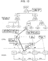
- FIG. 13 is a diagram illustrating an outline of safety quantitative evaluation processing according to the second embodiment.
- the processing corresponds to processing for calculating probability of occurrence of the top event.
- One of a plurality of events included in the FTA is selected, and a main function and a safety function are specified based on the detection target (refer to FIG. 7 ) of the logical function corresponding to the event and the failure function and the failure mode (refer to FIG. 10 ) of the logical function corresponding to the event.
- the failure rate (refer to FIG. 5 ) of the physical element corresponding to the specified main function and the detection rate (refer to FIG. 7 ) of the safety function for detecting a failure of the main function are obtained.
- a remaining failure rate (ratio of failure rate which cannot be detected) is calculated from the obtained failure rate and detection rate.
- the remaining failure rate of each event is integrated according to the condition of the tree, and the occurrence probability of the top event is calculated.
- FIG. 14 is a flowchart for explaining details of the safety quantitative evaluation processing according to the second embodiment.
- An architecture quantitative evaluation unit 103 calculates an occurrence probability (remaining failure rate) of a hazard (top event) according to the following procedure.
- a content of the processing to be executed by the architecture quantitative evaluation unit 103 as a program will be described.
- the architecture quantitative evaluation unit 103 can be replaced with the "processor".
- the architecture quantitative evaluation unit 103 repeats the processing in steps 1402 to 1405 on all the events of safety analysis information (FTA).
- FTA safety analysis information
- the architecture quantitative evaluation unit 103 searches the main function and the safety function of the event to be processed.
- main function since a logical function (main function) to be detected (in other word, monitored) is described in the detection target of the logical function (safety function) corresponding to the event, this information is extracted (main function A in example in FIG. 13 ).
- safety function A the corresponding safety function (here, safety function A) is specified based on the failure function and the failure mode (refer to FIG. 10 ) of the event to be processed.
- the architecture quantitative evaluation unit 103 obtains a failure rate corresponding to the failure mode that is a failure rate (refer to FIG. 5 ) described in a parameter of an ECU or a microcomputer (here, ECU 2) in which the main function A is allocated.
- the architecture quantitative evaluation unit 103 obtains the detection rate of the searched safety function (safety function A) from the parameter of the safety function (refer to FIG. 7 ).
- calculation is performed as assuming that the detected failure be reliably processed. In a case where there is no corresponding safety function, calculation is performed as assuming that the detection rate be zero.
- the architecture quantitative evaluation unit 103 calculates the occurrence probability of the top event according to the structure of the FTA tree.
- the occurrence probability of the top event is calculated according to the operation of the AND or OR gate.
- the remaining failure rates of the events are added at the OR gate, and an occurrence rate of an upper event is calculated by multiplying the remaining failure rates of the events at the AND gate. In this way, the quantitative evaluation of the safety is performed.
- the safety quantitative evaluation is performed in the safety requirement verification processing (step 1101), for example, the remaining failure rate of the hazard is compared with a required value for each hazard (for example, 10FIT in ASIL-D and the like). Then, it is determined that the verification is OK based on the result indicating that the remaining failure rate is equal to or less than the required value.
- a required value for each hazard for example, 10FIT in ASIL-D and the like.
- a third embodiment discloses that processing for verifying safety function cooperation (safety function cooperation verification processing) is executed in safety verification processing.
- the third embodiment is different from the first embodiment in that the safety function cooperation verification processing is further executed in the safety verification processing in FIG. 11 .
- the safety verification processing according to the third embodiment will be described.
- FIG. 15 is a flowchart for explaining an outline of the safety verification processing according to the third embodiment. As illustrated in FIG. 15 , steps 1501 and 1502 are added to the safety verification processing ( FIG. 11 : steps 1101 to 1104) according to the first embodiment. Only the added processing will be described below.
- a safety verification unit 102 verifies cooperation of safety functions in the physical architecture after allocation of a logical function. Details of the processing will be described later (refer to FIG. 16 ).
- the safety verification unit 102 determines whether the verification result of the safety function cooperation is OK as a result of the processing in step 1501. In a case where desired safety function cooperation is performed (yes in step 1502), the processing proceeds to step 1103. In a case where the desired safety function cooperation is not performed (no in step 1502), the processing proceeds to step 1104.
- FIG. 16 is a flowchart for explaining the details of the safety function cooperation verification processing (step 1501).
- the safety function cooperation verification processing to be executed by the safety verification unit 102 as a program will be described. However, since the program is read and executed by a processor of a vehicle control system verification device 100, the safety verification unit 102 can be replaced with the "processor".
- the safety verification unit 102 Since the safety function cooperation verification processing is executed for all safety functions of a logical architecture, the safety verification unit 102 obtains a safety control mode from a parameter of the safety function first.
- the safety control mode includes continuation of the function, safety stop, and the like, these kinds of information is obtained in correspondence with the safety function.
- the safety verification unit 102 checks a logical function as to whether the safety function cooperation is correctly performed according to the safety control mode.
- the check of the logical function means to compare the safety control model (refer to FIG. 7 ) with the cooperation of the safety functions as to whether cooperation of the logical functions corresponding to the obtained safety control mode is performed.
- FIG. 17 is a diagram illustrating an example of the safety control model.
- FIG. 17A illustrates the example of the safety control model corresponding to the "safety stop" of the safety control mode.
- FIG. 17B illustrates the example of the safety control model corresponding to the "continuation of the function" of the safety control mode.
- the reference “S" indicates Sensor
- the reference "A" indicates Actuator.
- the safety function (safety function A) having a "detection" function in a safety function type (refer to FIG. 7 ) of the parameter is coupled to main functions A, B, and C specified in the detection target (refer to FIG. 7 ) of the parameter.
- an output of the main function C is input to a safety function (safety function B) having a "switching function” in the safety function type (refer to FIG. 7 ).
- the safety verification unit 102 checks whether such cooperation is established in the logical architecture.
- the safety function (safety function A) having the “detection" function in the safety function type (refer to FIG. 7 ) of the parameter is coupled to main functions A, B, and C specified in the detection target (refer to FIG. 7 ) of the parameter.
- a safety function for performing control for "the continuation of the function” is required, and an output of the detection result is input to a safety function (safety function C) having a "control" function in the safety function type (refer to FIG. 7 ).
- the safety function C has an input (S) to perform the "control".
- safety function C an output result of the safety function
- safety function B the safety function for performing "switching".
- the safety verification unit 102 checks whether such cooperation is established in the logical architecture.
- the safety verification unit 102 determines whether the check result of the safety function cooperation in step 1602 is OK. In a case where the check result is not OK (no in step 1603), the processing proceeds to step 1604. In a case where the check result is OK (yes in step 1603), the processing proceeds to step 1605.
- the safety verification unit 102 In a case where the result of the logical function check in step 1603 is not OK, the safety verification unit 102 outputs that the check result of the corresponding safety requirement is not OK and the reason for the same. In this case, the safety requirement that causes the logical function check result to be not OK and lacked information on cooperation of the logical function are output.
- the safety verification unit 102 In a case where the check result of the safety requirement in step 1606 is not OK, the safety verification unit 102 outputs the result of not OK and the reason for the same. In this case, the safety requirements of which the safety degree and/or the multiplicity lacks and the information on the path are output as the reason for not OK.
- the safety verification unit 102 checks the safety requirement of the allocation destination and the path regarding the cooperation of the safety functions confirmed in step 1603.
- FIG. 18 is a diagram illustrating an example of check of the safety requirements of the allocation destination and the path regarding the cooperation of the safety functions.
- FIG. 18A illustrates an example in which the safety functions A and B are cooperated and a requirement of the safety degree of the function is ASIL-D.
- FIG. 18B illustrates an evaluation example in a case where the continuation of the function is further specified as the safety control mode of the safety function.
- the safety verification unit 102 confirms whether an ECU 1 and an ECU 3 which are allocation destinations, and a network (NW) 1, an ECU 2, and a NW 2 between the ECUs 1 and 3 safety the requested safety degree (ASIL-D). Furthermore, the multiplicity is similarly confirmed. In this way, the safety requirements at the time of function cooperation are checked.
- the functions are allocated as illustrated in FIG. 18B .
- the safety degree is determined as in a case of FIG. 18A .
- a function for "the continuation of the function” is added.
- redundant paths which are respectively independent for the main function and the safety function are required. This is because, in a case where the path of the main function cannot be used due to a failure and the like, it is necessary to realize a function similar to the main function having the failure through a different path. Therefore, the safety verification unit 102 searches a different path which is independent by using a path search algorithm.
- the safety verification unit 102 determines whether safety requirement check result of the safety function cooperation obtained in step 1605 is OK. In a case where the safety requirement check result is not OK (no in step 1606), the processing proceeds to step 1604. In a case where the safety requirement check result is OK (yes in step 1606), the processing proceeds to step 1607.
- the safety verification unit 102 outputs the result of OK (that the result of safety requirement check of safety function cooperation is OK).
- a fourth embodiment discloses a structure for verifying safety of a vehicle control system in a vehicle control system.
- FIG. 19 is a diagram illustrating an exemplary configuration (physical architecture) of the vehicle control system according to the fourth embodiment.
- a vehicle control system verification device 100 illustrated in FIG. 1 is arranged in an ECU 302, and safety verification processing is executed in the vehicle control system on the basis of a FTA that is supplied.
- the safety verification processing is mainly executed at the time of design.
- the safety verification processing can be executed when a control program is rewritten.
- the vehicle control system verification device 100 collects architecture information through a network link 301.
- FIG. 20 is a diagram illustrating an example of architecture configuration information received by the vehicle control system verification device 100 in the fourth embodiment.
- FIG. 20A illustrates physical architecture configuration information.
- FIG. 20B illustrates logical architecture configuration information.
- the physical architecture configuration information ( FIG. 20A ) includes each physical element name (ECU and microcomputer), a network name connected to the physical element, various parameters of the physical element (refer to FIG. 5 ) as configuration items.
- the physical architecture information is constructed by collecting information owned by the ECUs from the plurality of ECUs by the vehicle control system verification device 100.
- the logical architecture configuration information ( FIG. 20B ) includes each logical function name (ID), a physical element name (allocation place) which is allocated, and parameters of a logical architecture (refer to FIG. 7 ) as configuration items.
- the logical architecture information is constructed by collecting information owned by the ECUs from the plurality of ECUs by the vehicle control system verification device 100.
- the vehicle control system verification device 100 collects safety analysis information which has been previously held by the ECU 302 and the network link 301 in addition to the physical architecture configuration information and the logical architecture information. Then, the vehicle control system verification device 100 executes processing of vehicle control system verification and safety verification and outputs the verification result to a network and the like. As a result, it is possible to constantly verify the safety regarding the state of the vehicle control system.
- the vehicle control system verification device 100 obtains only a difference, updates the difference, and makes determination. With this operation, a communication amount can be reduced.
- the vehicle control system verification device performs quantitative evaluation on the physical architecture (for example, including a plurality of physical elements and network). Specifically, by calculating a use rate of a plurality of physical elements and an occupancy rate of the network when the logical architecture is allocated in the physical element, the quantitative evaluation of the physical architecture can be performed.
- the embodiments of the present invention can be realized by a program code of software for realizing the functions.
- a storage medium recording the program code is provided in a system or a device, and a computer (or CPU and MPU) of the system or the device reads the program code stored in the storage medium.
- the program code read from the storage medium realizes the functions of the embodiments described above, and the program code itself and the storage medium storing the program code are included in the present invention.
- a storage medium for supplying such as program code for example, a flexible disk, a CD-ROM, a DVD-ROM, a hard disk, an optical disk, a magneto-optical disk, a CD-R, a magnetic tape, a nonvolatile memory card, a ROM, and the like are used.
- an operating system (OS) and the like operating in the computer executes a part of or all of the actual processing and the processing realizes the functions of the embodiments.
- OS operating system
- a CPU and the like of the computer performs a part of or all of the actual processing and the processing realizes the functions of the embodiments.
- the program code of software for realizing the function of the embodiment is distributed via the network so that the distributed program code is stored in a storage unit such as a hard disk, a memory, and the like of the system and the device or the storage medium such as a CD-RW and a CD-R, and the computer (or CPU and MPU) may read and execute the program code stored in the storage unit and the storage medium at the time of using the program code.
- a storage unit such as a hard disk, a memory, and the like of the system and the device or the storage medium such as a CD-RW and a CD-R
- the computer or CPU and MPU
- control line and an information line which are considered to be necessary for description are illustrated, and all the control lines and information lines are not necessarily illustrated in a product. All the configurations may be mutually connected.
Landscapes
- Engineering & Computer Science (AREA)
- Theoretical Computer Science (AREA)
- Physics & Mathematics (AREA)
- General Engineering & Computer Science (AREA)
- General Physics & Mathematics (AREA)
- Automation & Control Theory (AREA)
- Computer Hardware Design (AREA)
- Transportation (AREA)
- Mechanical Engineering (AREA)
- Quality & Reliability (AREA)
- Human Computer Interaction (AREA)
- Evolutionary Computation (AREA)
- Geometry (AREA)
- Debugging And Monitoring (AREA)
- Valves And Accessory Devices For Braking Systems (AREA)
- Safety Devices In Control Systems (AREA)
- Testing And Monitoring For Control Systems (AREA)
- Traffic Control Systems (AREA)
Description
- The present invention relates to a vehicle control system verification device, a vehicle control system, and a vehicle control system verification method.
- In recent years, electronic control of an automobile has been rapidly complicated, and it is necessary to cope with the complicated electronic control. A more reliable vehicle control system is desired. To realize such as vehicle control system, it is desirable to inspect reliability of each function implemented in the vehicle control system.
- For example,
PTL 1 discloses that safety and reliability of a software-based electronic system are examined based on a hardware component of a system which is required for a function by using the reliability function to examine a required function of a system. Furthermore,PTL 2 discloses an improved method for design and verification of a safety-oriented system. According toPTL -
- PTL 1:
JP 2007-506591 W - PTL 2:
JP 2007-528532 W - Non-Patent Literature 1: Karla Ducharme: "CTI ISO 26262: Integration of Functional Safety into the Engineering Workflow integration of Functional Safety into the Engineering Workflow 2nd", Detroit Marriot Troy, 2 October 2015 (2015-10-02), pages 14-16, XP055639580. Non-Patent Literature 1 describes a method for evaluation of computational models of safety functions of a vehicle in a development environment.
- However,
PTLs PTLs - The present invention has been made in consideration of the above state and provides a technology for comprehensively verifying the safety of design of the function based on the safety analysis result.
- The above problems are solved by the features of
claim 1. The dependent claims relate to preferred embodiments. - Further features related to the present invention will be apparent with reference to the description herein and the accompanying drawings. Furthermore, the aspects of the present invention are achieved and realized by elements and combinations of various elements, detailed description below, and aspects in the attached claims.
- The description in the specification is merely exemplary, and it is necessary to understand that the description herein does not limit the scope of claims of the present invention; the invention is defined and limited by the appended claims.
- According to the present invention, a design based on a logical architecture, a physical architecture, and function allocation information of an automatic operation system can be comprehensively verified on the basis of safety analysis information.
-
- [
FIG. 1] FIG. 1 is a diagram illustrating a schematic configuration of a vehicle controlsystem verification device 100 according to an embodiment of the present disclosure. - [
FIG. 2] FIG. 2 is a diagram illustrating an exemplary schematic configuration of avehicle system 1 including a vehicle control system to be evaluated. - [
FIG. 3] FIG. 3 is a diagram illustrating an example of a physical architecture of avehicle control system 2. - [
FIG. 4] FIG. 4 is a diagram illustrating an internal configuration example of anECU 302. - [
FIG. 5] FIG. 5 is a diagram illustrating an example of parameters of aphysical architecture 20. - [
FIG. 6] FIG. 6 is a diagram illustrating an exemplary configuration of alogical architecture 601 of the vehicle control system (for example, first vehicle control system 2). - [
FIG. 7] FIG. 7 is a diagram illustrating an example of parameters of thelogical architecture 601. - [
FIG. 8] FIG. 8 is a diagram illustrating an exemplary configuration of a case where a logical architecture is allocated in a physical architecture. - [
FIG. 9] FIG. 9 is a diagram illustrating an example of Fault Tree Analysis (FTA) that can be used as safety analysis information. - [
FIG. 10] FIG. 10 is a diagram illustrating an example of parameters applied to each event and each gate of the FTA. - [
FIG. 11] FIG. 11 is a flowchart for explaining an outline of safety verification processing according to a first embodiment. - [
FIG. 12] FIG. 12 is a flowchart for explaining details of safety requirement verification processing (step 1102). - [
FIG. 13] FIG. 13 is a diagram illustrating an outline of safety quantitative evaluation processing according to a second embodiment. - [
FIG. 14] FIG. 14 is a flowchart for explaining details of the safety quantitative evaluation processing according to the second embodiment. - [
FIG. 15] FIG. 15 is a flowchart for explaining an outline of safety verification processing according to a third embodiment. - [
FIG. 16] FIG. 16 is a flowchart for explaining details of safety function cooperation verification processing (step 1501). - [
FIG. 17] FIG. 17 is a diagram illustrating an example of a safety control model. - [
FIG. 18] FIG. 18 is a diagram illustrating an example of check of safety requirements of an allocation destination and a path regarding cooperation of safety functions. - [
FIG. 19] FIG. 19 is a diagram illustrating an exemplary configuration (physical architecture) of a vehicle control system according to a fourth embodiment. - [
FIG. 20] FIG. 20 is a diagram illustrating an example of architecture configuration information received by a vehicle controlsystem verification device 100 in the fourth embodiment. - A vehicle control system verification device according to embodiments of the present invention comprehensively verifies safety of a design of functions and appropriateness of allocation on the basis of safety analysis result that is supplied and verifies whether necessary requirements are satisfied and whether safety functions are cooperated with each other. Specifically, the vehicle control system verification device according to the present disclosure verifies whether a logical architecture of a vehicle control system has logical functions coping with the safety analysis result on the basis of the safety analysis result (FTA) information that is supplied. Note that the logical architecture may be constructed on the basis of the safety analysis result information. This is because the verification of the safety function at the time of design is to design an architecture so as to satisfy the safety requirements of the FTA and to check whether the architecture actually satisfies the safety requirements of the FTA to be a target.
- Furthermore, the vehicle control system verification device verifies whether a physical architecture of the vehicle control system satisfies a safety degree and multiplicity required by the logical architecture.
- Hereinafter, preferred embodiments of the present invention will be described in more detail. In the embodiments, a verification device of a vehicle control system is mainly described, and the embodiment is preferable for the verification of the vehicle control system. However, this is not intended to prevent an application of the embodiments to the other systems.
- A first embodiment discloses verification whether a safety function required for the FTA exists in a logical architecture of a vehicle control system and whether a safety degree and multiplicity required for the physical architecture are satisfied when the logical architecture is allocated in the physical architecture of the vehicle control system.
-
FIG. 1 is a diagram illustrating a schematic configuration of a vehicle controlsystem verification device 100 according to an embodiment of the present invention. - The vehicle control
system verification device 100 includes afunction allocation unit 101, asafety verification unit 102, and an architecturequantitative evaluation unit 103. - For example, the
function allocation unit 101 receives thelogical architecture 601 and thephysical architecture 20, and executes a process for allocating thelogical architecture 601 in thephysical architecture 20 as in an example of function allocation (refer toFIG. 8 ). - The
safety verification unit 102 receives the architecture after function allocation and safety analysis information (for example, Fault Tree Analysis (FTA) (refer toFIG. 9 )) 900 and verifies safety of the architecture designed according to a flow of safety verification proposed in the present invention . Then, thesafety verification unit 102 outputs that the safety verification is OK or the safety verification is not OK and the reason for the same as verification result to thefunction allocation unit 101. Note that the verification result may be directly output to the architecturequantitative evaluation unit 103. - The architecture
quantitative evaluation unit 103 receives the verification result of the safety of the architecture and performs quantitative evaluation mainly on the architecture of which the safety verification has been determined as OK and outputs evaluation result. - As described above, the vehicle control
system verification device 100 verifies and evaluates the vehicle control system. - The vehicle control
system verification device 100 may be realized by a computer including a processor (CPU and the like), a memory (ROM, RAM, and the like), and the like. In this case, thefunction allocation unit 101, thesafety verification unit 102, and the architecturequantitative evaluation unit 103 are configured by programs, and the processor reads various programs from a program memory (ROM) and executes the read program. - Details of the
logical architecture 601, thephysical architecture 20, thefunction allocation unit 101, and thesafety verification unit 102 will be described later. -
FIG. 2 is a diagram illustrating an exemplary schematic configuration of avehicle system 1 including a vehicle control system to be evaluated. Thevehicle system 1 corresponds to an automobile and the like, and includes the vehicle control system therein. - For example, the
vehicle system 1 includes a firstvehicle control system 2, at least onecommunication device 3, a secondvehicle control system 4, at least onedriving device 5, at least onerecognition device 6, anoutput device 7, aninput device 8, and anotification device 9. Here, two vehicle control systems (firstvehicle control system 2 and second vehicle control system 4) are exemplified. However, the number of vehicle control systems is not limited to two. Furthermore, a configuration in which a plurality of vehicle control systems is operated in cooperation with each other may be employed. - The first
vehicle control system 2 includes, for example, an in-vehicle network (Controller Area Network (CAN), CAN with Flexible Data-rate (CANFD), Ethernet (registered trademark), and the like) and a controller (Electronic Control Unit (ECU) and the like). The firstvehicle control system 2 is connected to the secondvehicle control system 4, thecommunication device 3, the drivingdevice 5, therecognition device 6, theoutput device 7, theinput device 8, and thenotification device 9 and exchanges information with each of the devices. - The
communication device 3 performs wireless communication to outside of the vehicle system 1 (for example, communication with mobile phone, communication using a protocol such as wireless LAN, WAN, and Car to X (C2X: vehicle-to-vehicle or vehicle-to-infrastructure communication, or communication using Global Positioning System (GPS)), performs wireless communication to obtain or transmit information on the outside (for example, infrastructure, other vehicle, and map) or information on the vehicle itself (for example, information indicating state of vehicle), or has a diagnostic terminal (OBD), an Ethernet (registered trademark) terminal, an external recording medium (for example, USB memory and SD card) terminal, and the like to communicate with the firstvehicle control system 2. - For example, the second
vehicle control system 4 is a vehicle control system including a network using a protocol different from or same as that of the firstvehicle control system 2. - The driving
device 5 drives machines and electric devices for controlling an vehicle motion (for example, engine, transmission, wheel, brake, and steering device) according to the control of the firstvehicle control system 2 and corresponds to, for example, an actuator. - The
recognition device 6 includes an external sensor such as a camera, a radar, an LIDAR, an ultrasonic sensor, and the like that outputs information to obtain information input from outside and to generate information and a dynamical system sensor that recognizes a state of the vehicle system 1 (motion state, position information, acceleration, wheel speed, and the like). - The
output device 7 is connected to a network system (for example, the in-vehicle network) in a wired or wireless manner, receives data transmitted from the network system, and displays or outputs necessary information such as message information (for example, video, sound). For example, theoutput device 7 corresponds to a liquid crystal display, a warning lamp, a speaker, and the like. - The
input device 8 generates an input signal to input an intention and an instruction of an operation to the firstvehicle control system 2 by a user and corresponds to, for example, a steering, a pedal, a button, a lever, and a touch panel. - The
notification device 9 is used to notify outside of a state of the vehicle and the like by thevehicle system 1 and corresponds to, for example, a lamp, an LED, and a speaker. -
FIG. 3 is a diagram illustrating an example of a physical architecture of thevehicle control system 2. Thephysical architecture 20 can be referred to as a hardware (H/W) configuration. - The
physical architecture 20 includes, for example, anetwork link 301 and Electronic Control Units (ECU) 302. - The
network link 301 is a network link to connect network devices on the in-vehicle network and corresponds to, for example, a network link such as a CAN bus. - The
ECU 302 is connected to thenetwork link 301, the drivingdevice 5, therecognition device 6, and a network link (including dedicated line) other than 301 to control thedriving device 5 and therecognition device 6, to obtain information, and to exchange data with the network. TheECU 302 is connected to the plurality ofnetwork links 301 and plays a role of a gateway (referred to as GW below) for exchanging data with each of the network links. - Other than a bus-type example in which the plurality of ECUs is connected to two buses illustrated in
FIG. 3 , as an exemplary configuration of a network topology, a star type in which the plurality of ECU is directly connected to the GW, a link type in which the ECUs are connected in a ring-like shape as a string of link, and a mixed type in which various types are mixed and the plurality of networks is included can be employed. Based on the data received from the network, theECU 302 executes control processing such as to output a control signal to thedriving device 5, to obtain information from therecognition device 6, to output the control signal and the information to the network, and to change an internal state. - Here, the
ECU 302, thenetwork link 301, and the processor in the ECU may also be referred to as physical elements below. -
FIG. 4 is a diagram illustrating an internal configuration example of theECU 302. TheECU 302 includes, for example, aprocessor 401, an Input/Output (I/O)device 402, atimer 403, a Read Only Memory (ROM) 404, a Random Access Memory (RAM) 405, and aninternal bus 406 as the internal configuration. - The
processor 401 includes a storage element such as a cache and a register and performs control. For example, theprocessor 401 includes a CPU. Theprocessor 401 executes a logical function to be described later. - The I/
O device 402 exchanges data with thenetwork link 301 or thedriving device 5 or/and therecognition device 6 connected via the network or a dedicated line. The I/O device 402 can include, for example, a communication interface (I/F). - The
timer 403 uses a clock (not shown) or the like to manage time. - The
ROM 404 stores a program and nonvolatile data. TheRAM 405 stores programs and volatile data. Theinternal bus 406 is used for communication in theECU 302. -
FIG. 5 is a diagram illustrating an example of parameters of thephysical architecture 20.FIG. 5A illustrates parameters applied to the physical elements (ECU and processor) of thephysical architecture 20.FIG. 5B illustrates parameters applied to the network. - As illustrated in
FIG. 5A , the parameters of the physical element include an operation performance, a RAM amount, a ROM amount, an available safety degree, a cost, a multiplicity, a failure rate, a diagnosis rate, and physical dependency. In the parameters, the operation performance (MHz: performance of processor), the RAM amount (KB: capacity), the ROM amount (KB: capacity), and the cost (yen: price of ECU or processor) are used in quantitative evaluation of an architecture having the parameters of the ECU or the processor. - The available safety degree is a parameter related to safety and information indicating a safety level with which the physical element can cope as hardware (ECU). The available safety degree is specified in ISO26262 and corresponds to, for example, the Automotive Safety Integrity Level (ASIL) and the Quality Management (QM).
- The multiplicity is information indicating the number of systems included in the ECU. For example, if the ECU has a dual system and can cape with a failure of one system, it is assumed that the multiplicity be two (the number of multiplicities).
- The failure rate is information indicating time in which a single failure occurs when the physical element (ECU and processor) continuously operates (Failure in time) and used for safety verification.
- The diagnosis rate indicates a coverage of diagnosis regarding a function of the physical element (for example, microcomputer diagnosis). For example, this indicates that the physical element can cope with 99% of failures and cannot cope with remaining one% of failures if the diagnosis rate is 99%. The failure with which the physical element cannot cope may be recognized at the time of design.
- The physical dependency is information indicating the hardware on which the physical element depends (for example, a case where ECU and another ECU are connected to the same power supply).
- As illustrated in
FIG. 4 , in a case where a microcomputer (processor) is arranged in the ECU, the parameter is applied to one of the ECU and the processor at the time of verification, and the applied parameter is used. In a case where the parameters are applied to both of the ECU and the microcomputer in this way, in consideration of the safety, the parameter which outputs worse result (for example, lower value as ASIL) is used for the verification. Accordingly, high verification result is not wrongly output, and safety as a whole can be secured. - Here, regarding the failure rate and the diagnosis rate, an example in which the same parameters are applied to all the failure modes is described. However, different parameters may be used for the respective failure modes of each element. By using the parameters in this way, the verification and the evaluation based on the failure rate and the diagnosis rate according to the failure mode are available, and more detailed quantitative evaluation and verification can be realized.
- As illustrated in
FIG. 5B , the network includes parameters of a communication speed (bps), a cost (yen: price of network cable), and multiplicity (communication line redundancy). -
FIG. 6 is a diagram illustrating an exemplary configuration of thelogical architecture 601 of the vehicle control system (for example, first vehicle control system 2). - The
logical architecture 601 of the vehicle control system includes, for example, anintegration recognition unit 602, an automaticdrive control unit 603, auser input unit 604, anoutput management unit 605, anotification management unit 606, anabnormality detection unit 607, aswitching unit 608, amotion control unit 609, and asafety control unit 610. - The
integration recognition unit 602 executes a process for creating an outside recognition map formed by integrating outside recognition information transmitted from the plurality ofrecognition devices 6 and thecommunication device 3. - The automatic
drive control unit 603 generates automatic drive control information (trajectory and the like) based on the outside recognition map generated by theintegration recognition unit 602 and a user input from theuser input unit 604 and outputs the generated information to theabnormality detection unit 607 and theswitching unit 608. Furthermore, the automaticdrive control unit 603 issues an output instruction to theoutput management unit 605 and issues a notification instruction to thenotification management unit 606. Theoutput management unit 605 issues an output instruction to theoutput device 7 according to the outputs of the automaticdrive control unit 603 and theabnormality detection unit 607. Thenotification management unit 606 issues a notification instruction to thenotification device 9 according to the outputs of the automaticdrive control unit 603 and theabnormality detection unit 607. - The
user input unit 604 generates user instruction information according to the input from theinput device 8. - The
abnormality detection unit 607 detects an abnormality on the basis of the automatic drive control information and the like from the automaticdrive control unit 603 and predetermined information from each unit which is not shown and outputs abnormality detection result to theswitching unit 608, thesafety control unit 610, theoutput management unit 605, and thenotification management unit 606. - According to the abnormality detection result of the
abnormality detection unit 607 and the like, theswitching unit 608 switches an output to themotion control unit 609 to an input from the automaticdrive control unit 603, an input from theuser input unit 604, or an input from thesafety control unit 610. Specifically, when theabnormality detection unit 607 detects an abnormality, a normal control system (also referred to as main control system: 602→603→608→609) from the automaticdrive control unit 603 is switched to a control system at the time of abnormality (also referred to as safe control system: 602→610→608→609). - The
motion control unit 609 controls the plurality of drivingdevices 5 according to trajectory information or motion control information provided from theswitching unit 608, the state of thevehicle system 1 obtained from therecognition device 6, and a response from the drivingdevice 5. - The
safety control unit 610 performs control in a case of receiving a notification that the abnormality has been detected. Thesafety control unit 610 has a degeneracy function of the automaticdrive control unit 603 and can alternatively execute a part of the function of the automaticdrive control unit 603 in an emergency. - In the example illustrated in
FIG. 6 , a function for performing main control at the normal time is referred to as a main function, and a function for performing main control at the time of detecting the abnormality or at the time after the abnormality has occurred is referred to as a safety function. The main function corresponds to theintegration recognition unit 602, the automaticdrive control unit 603, theuser input unit 604, theoutput management unit 605, thenotification management unit 606, and themotion control unit 609. The safety function corresponds to theabnormality detection unit 607, theswitching unit 608, and thesafety control unit 610. -
FIG. 7 is a diagram illustrating an example of parameters of thelogical architecture 601.FIG. 7A illustrates parameters applied to the main functions.FIG. 7B illustrates parameters applied to the safety functions.FIG. 7C illustrates a parameter for logical connection. - The parameters of the main function include a type of a logical function, an operation amount, a consumption RAM, and a consumption ROM.
- The type of the logical function is information indicating the type of the logical function and used for determination of the main function or the safety function. Here, the "main function" is input.
- The operation amount (MHz) is information indicating a performance of the ECU or the processor necessary for executing the function. The consumption RAM (KB) is information indicating a consumption amount of the RAM necessary for executing the function. The consumption ROM (KB) is information indicating a consumption amount of the ROM necessary for executing the function.
- The operation amount, the consumption RAM, and the consumption ROM are mainly used for quantitative evaluation of the architecture.
- The parameters of the safety function include a type of the logical function, a type of the safety function, a safety control mode, an operation amount, a consumption RAM, a consumption ROM, a required safety degree, a detection target, a detection failure mode, a detection rate, and an independence requirement.
- The type of the logical function is information indicating the type of the logical function and used for determination of the main function or the safety function. Here, the "safety function" is input. The operation amount (MHz) is information indicating a performance of the ECU or the processor necessary for executing the function. The consumption RAM (KB) is information indicating a consumption amount of the RAM necessary for executing the function. The consumption ROM (KB) is information indicating a consumption amount of the ROM necessary for executing the function. The operation amount, the consumption RAM, and the consumption ROM are mainly used for quantitative evaluation of the architecture. The type of the logical function, the operation amount, the consumption RAM, the consumption ROM are used for the quantitative evaluation of the architecture similarly to the main function.
- The type of the safety function is information indicating the type of the corresponding safety function and used for determination safety function cooperation to be described later. For example, the type of the safety function indicates which one of detection, control, and switch the safety function corresponds to.
- The safety control mode is information indicating a content required for safety control to be realized by the safety function. For example, information such as function stop and function continuation is applied. In addition, the safety control mode includes information on the required multiplicity.
- The required safety degree is information indicating a safety degree required for the safety function. For example, QM and ASIL are applied, and execution of the safety function with the safety degree is required in the physical architecture.
- The detection target is information indicating a logical function of which an event (for example, abnormality) is a detection target to be detected by the safety function. For example, when the function is the
abnormality detection unit 607, the detection target is theintegration recognition unit 602 and the automaticdrive control unit 603. - The detection failure mode is information indicating a failure mode from among the plurality of failure modes (for example, stop at the time of failure, output false value at the time of failure, output value with delay at the time of failure, and the like) corresponding to the logical function.
- The detection rate is information indicating whether a range of failures and errors can be detected by the safety function as in the "diagnosis rate" of the physical element. For example, in a case where the detection rate is 99%, although 99% of the failures and errors can be detected, remaining one% of the failures and errors cannot be detected.
- The independence requirement is information indicating a name of a logical function which should not be failed at the same time as the time of the failure of the safety function. The independence requirement is a parameter to prevent the design such as a common-cause failure and a subordinate failure in which failures concurrently occur in the safety function and the main function, resulting in unavailability in the safety control.
- A parameter relative to logical connection includes a communication amount of the communication path. The communication amount is used for the quantitative evaluation of the architecture.
(iv) Regarding the parameters described above, there are essential combinations at the time of architecture design. Therefore, when the essential parameters are not applied, it is necessary to determine that the architecture verification is not OK. For example, in spite of the type of the safety function which is "detection", in a case where the parameters such as the detection target, the detection failure mode, the detection rate, and the like are not applied, Not OK is output at the time of safety verification. -
FIG. 8 is a diagram illustrating an exemplary configuration of a case where a logical architecture is allocated in a physical architecture. - The
function allocation unit 101 allocates the applied logical architecture 601 (refer toFIG. 6 ) in the applied physical architecture 20 (refer toFIG. 3 ). As a result, the physical element (ECU and microcomputer) which executes a process of the logical function, the logical function to be processed, and the content of the communication in the network are determined. - In the allocation example in
FIG. 8 , the logical functions having strong relationships with each other are allocated in the same ECU. For example, theintegration recognition unit 602, the automaticdrive control unit 603, theuser input unit 604, and theoutput management unit 605 which are the main functions are allocated in the same ECU. Theabnormality detection unit 607 and thesafety control unit 610 which are the safety functions are allocated in the same ECU. Furthermore, theswitching unit 608 which is the safety function and themotion control unit 609 which is the main function are allocated in the same ECU. - Note that a plurality of paths is provided in the network between the logical functions, for example, it is preferable to perform efficient communication by selecting a path that causes the minimum cost (communication band, the number of hops) from among the provided paths.
-
FIG. 9 is a diagram illustrating an example of Fault Tree Analysis (FTA) that can be used as safety analysis information. AFTA 900 has a tree-like structure and includes a top event 901,events 903 which form respective leaves, andbranch gates 902. - The top event (event at top of tree) is considered as a hazard event (dangerous event), coupled to lower events through AND gates or OR gates, and decomposed into the lower events which cause the top event. The OR gate means that the upper event occurs when one of the events occurs, and the AND gate means that the upper event occurs only when both of the events occur. In this way, relationship between the events that cause the highest hazard can be clarified.
-
FIG. 10 is a diagram illustrating an example of parameters applied to each event and each gate.FIG. 10A illustrates parameters applied to each event.FIG. 10B illustrates the parameters applied to each gate. - The parameters of the event include an event or a gate positioned on the upper side of the event (upper event or upper gate), an event type (intermediate event or basic event), a failure function, and a failure mode as configuration items. A combination of the failure function and the failure mode represents a content of the event. The failure function and the failure mode are described not only in the basic event but also in the intermediate event. With this description, for example, not only a failure of a component but also a system failure can be described.
- Regarding the failure function, a table (not shown) indicating the content of the logical function is additionally provided, and the content of each logical function can be recognized with reference to the table.
- The parameters of the gate include an event and a gate positioned on the upper side of each gate and a gate type (OR or AND) as configuration items.
(iii) With the above parameters, in a case where any one of events (failure in logical function) occurs, a condition which causes the hazard can be expressed. -
FIG. 11 is a flowchart for explaining an outline of safety verification processing according to the first embodiment. An outline of the processing to be performed by thesafety verification unit 102 as a program will be described below. However, since the program is read and executed by the processor of the vehicle controlsystem verification device 100, thesafety verification unit 102 can be replaced with the "processor". - First, the
safety verification unit 102 executes the safety requirement verification processing on an architecture after function allocation. Details of the safety requirement verification processing will be described later (refer toFIG. 12 ). - In a case where safety requirement verification result is OK (yes in S1102), the
safety verification unit 102 proceeds the processing to step 1103, and in a case where the safety requirement verification result is not OK (no in S1102), thesafety verification unit 102 proceeds the processing to step 1104. - The
safety verification unit 102 outputs OK as the safety verification result and terminates the processing. - The
safety verification unit 102 outputs the result of not OK, a reason for the same, and the safety requirement of which the verification has not been valid. In this way, the safety requirements are verified. -
FIG. 12 is a flowchart for explaining the details of the safety requirement verification processing (step 1102). - In the safety requirement verification processing, the
safety verification unit 102 repeats processing insteps 1202 to 1205 on all the events of thesafety analysis information 900. - For each event, the
safety verification unit 102 confirms whether the corresponding safety function exists on the architecture. Specifically, it is checked whether the parameter of the failure function (for example,logical function 1 inFIG. 10 ) of the event (for example, ET3) (to be processed) exists in the detection failure mode and the detection target of the corresponding safety function. In a case where the corresponding safety function exists (yes in step 1202), the processing proceeds to step 1203. In a case where there is no corresponding safety function (no in step 1202), the processing proceeds to step 1205. - The
safety verification unit 102 determines whether requirements in the safety degree and the multiplicity are satisfied in the allocation destination of the safety function in thephysical architecture 20. - In a case of the safety, in a case where a value of the required safety degree which is the parameter of the safety function is smaller than or equal to the available safety degree of the physical element of the allocation destination, it is determined that the required safety degree is OK. Specifically, in a case where the required safety degree of the safety function is ASIL-C, if the available safety degree of the physical element of the allocation destination is the ASIL-C or equal to or more than that (ASIL-D and the like), it is determined that the required safety degree is OK.
- In a case of the multiplicity, in a case where a value of required multiplicity included in the safety control mode which is the parameter of the safety function is smaller than or equal to the multiplicity of the physical element of the allocation destination, it is determined that the multiplicity is OK. Specifically, in a case where the required multiplicity of the safety function is two, if the multiplicity of the physical element of the allocation destination is equal to or more than two, it is determined that the multiplicity is OK.
- In a case where the safety degree and the multiplicity of the allocation destination are OK (yes in step 1203), the processing proceeds to step 1204. In a case where the safety degree and the multiplicity of the allocation destination are not OK (no in step 1203), the processing proceeds to step 1205.
- The
safety verification unit 102 determines that the content of the event is OK. - The
safety verification unit 102 determines that the content of the event is not OK. - The
safety verification unit 102 executes processing on the next event. After processing on all the events has been completed, the processing proceeds to step 1207. - The
safety verification unit 102 makes determination on the safety requirement verification by applying the processing results of steps 1201 to 1206 to the tree of the FTA. Specifically, for each event of the FTA, thesafety verification unit 102 inputs the results indicating OK or not OK regarding each event to the FTA and makes determination according to the tree of the FTA. That is, as passing through OK and not OK in the tree from each event to the top, determination at each gate is made as AND or OR, and it is determined whether the highest event occurs. Here, thesafety verification unit 102 makes determination with an AND condition and an OR condition as setting not OK as T (True) and OK as F (False). Then, OK is returned in a case where the top event is False, and not OK is returned in a case of True. The overall safety requirement is verified in this way. - In a case where the top event is not OK, all the recorded events which are not OK are returned. With this processing, the vehicle control
system verification device 100 can present the safety requirement having an error relative to a user. - In
step 1203, only the determination on the safety degree may be made in the verification processing of the allocation destination. Since the multiplicity is additionally verified in the safety function cooperation, the verification of the multiplicity can be omitted instep 1203. With this omission, an operation amount can be reduced. - Furthermore, in
step 1207, the determination in the FTA tree is not made, and in a case where any one of the events is not OK, it is possible to determine that the safety requirement verification is not OK based on the result and to terminate the safety requirement verification processing. By determining that the safety function should correspond to all the safety requirements, processing time can be reduced without performing an operation of the FTA tree. - The architecture
quantitative evaluation unit 103 performs quantitative evaluation on an architecture to which functions have been allocated and of which the safety verification result has been determined to be OK. The quantitative evaluation can be realized by, for example, calculating a use rate of the logical function on the physical element, calculating an occupancy rate in communication, and calculating a cost of the physical element. The use rate of the logical function on the physical element can be calculated by calculating a total value of each of the operation amount, the consumption RAM, and the consumption ROM regarding each of the plurality of logical functions arranged in the physical element of thephysical architecture 20 and calculating the use rate on the physical element. Furthermore, the occupancy rate in communication can be calculated by summing up use amounts of communication of each logical function on the network and calculating the occupancy rate. In addition, the cost of the physical element can be calculated by adding costs of physical elements used in the entire physical architecture, that is, the cost of the physical elements in which one or more logical functions are allocated. - With this calculation, the quantitative evaluation on the architecture of which the safety has been verified can be performed. The quantitative evaluation may be performed only on the architectures of which the safety has been verified. With this evaluation, it is possible to reduce unnecessary evaluation time of the architecture of which the safety is not satisfied.
- A second embodiment discloses another form of verification and evaluation based on quantitative evaluation of safety. Specifically, the safety requirement verification (step 1101) according to the first embodiment or another form of the processing (safety quantitative evaluation processing: can be referred to as top event occurrence probability calculation processing) executed in the architecture quantitative evaluation described above will be described.
-
FIG. 13 is a diagram illustrating an outline of safety quantitative evaluation processing according to the second embodiment. The processing corresponds to processing for calculating probability of occurrence of the top event. - One of a plurality of events included in the FTA is selected, and a main function and a safety function are specified based on the detection target (refer to
FIG. 7 ) of the logical function corresponding to the event and the failure function and the failure mode (refer toFIG. 10 ) of the logical function corresponding to the event. - The failure rate (refer to
FIG. 5 ) of the physical element corresponding to the specified main function and the detection rate (refer toFIG. 7 ) of the safety function for detecting a failure of the main function are obtained. - Next, a remaining failure rate (ratio of failure rate which cannot be detected) is calculated from the obtained failure rate and detection rate.
- Then, the remaining failure rate of each event is integrated according to the condition of the tree, and the occurrence probability of the top event is calculated.
-
FIG. 14 is a flowchart for explaining details of the safety quantitative evaluation processing according to the second embodiment. An architecturequantitative evaluation unit 103 calculates an occurrence probability (remaining failure rate) of a hazard (top event) according to the following procedure. Here, a content of the processing to be executed by the architecturequantitative evaluation unit 103 as a program will be described. However, since the program is read and executed by the processor of a vehicle controlsystem verification device 100, the architecturequantitative evaluation unit 103 can be replaced with the "processor". - The architecture
quantitative evaluation unit 103 repeats the processing insteps 1402 to 1405 on all the events of safety analysis information (FTA). - The architecture
quantitative evaluation unit 103 searches the main function and the safety function of the event to be processed. Regarding the main function, since a logical function (main function) to be detected (in other word, monitored) is described in the detection target of the logical function (safety function) corresponding to the event, this information is extracted (main function A in example inFIG. 13 ). - Regarding the safety function, the corresponding safety function (here, safety function A) is specified based on the failure function and the failure mode (refer to
FIG. 10 ) of the event to be processed. - The architecture
quantitative evaluation unit 103 obtains a failure rate corresponding to the failure mode that is a failure rate (refer toFIG. 5 ) described in a parameter of an ECU or a microcomputer (here, ECU 2) in which the main function A is allocated. - The architecture
quantitative evaluation unit 103 obtains the detection rate of the searched safety function (safety function A) from the parameter of the safety function (refer toFIG. 7 ). - The architecture
quantitative evaluation unit 103 calculates a remaining failure rate of the event to be processed by applying the obtained failure rate and detection rate to (Expression 1).
- Here, the calculation is performed as assuming that the detected failure be reliably processed. In a case where there is no corresponding safety function, calculation is performed as assuming that the detection rate be zero.
- After calculating the remaining failure rates of all the events, the architecture
quantitative evaluation unit 103 calculates the occurrence probability of the top event according to the structure of the FTA tree. Here, after the remaining failure rate of each event has been calculated, the occurrence probability of the top event is calculated according to the operation of the AND or OR gate. In addition, here, it is considered that all the events are independent from each other, the remaining failure rates of the events are added at the OR gate, and an occurrence rate of an upper event is calculated by multiplying the remaining failure rates of the events at the AND gate. In this way, the quantitative evaluation of the safety is performed. - In a case where the safety quantitative evaluation is performed in the safety requirement verification processing (step 1101), for example, the remaining failure rate of the hazard is compared with a required value for each hazard (for example, 10FIT in ASIL-D and the like). Then, it is determined that the verification is OK based on the result indicating that the remaining failure rate is equal to or less than the required value.
- A third embodiment discloses that processing for verifying safety function cooperation (safety function cooperation verification processing) is executed in safety verification processing. The third embodiment is different from the first embodiment in that the safety function cooperation verification processing is further executed in the safety verification processing in
FIG. 11 . Hereinafter, the safety verification processing according to the third embodiment will be described. -
FIG. 15 is a flowchart for explaining an outline of the safety verification processing according to the third embodiment. As illustrated inFIG. 15 ,steps 1501 and 1502 are added to the safety verification processing (FIG. 11 :steps 1101 to 1104) according to the first embodiment. Only the added processing will be described below. - A
safety verification unit 102 verifies cooperation of safety functions in the physical architecture after allocation of a logical function. Details of the processing will be described later (refer toFIG. 16 ). - The
safety verification unit 102 determines whether the verification result of the safety function cooperation is OK as a result of the processing in step 1501. In a case where desired safety function cooperation is performed (yes in step 1502), the processing proceeds to step 1103. In a case where the desired safety function cooperation is not performed (no in step 1502), the processing proceeds to step 1104. -
FIG. 16 is a flowchart for explaining the details of the safety function cooperation verification processing (step 1501). The safety function cooperation verification processing to be executed by thesafety verification unit 102 as a program will be described. However, since the program is read and executed by a processor of a vehicle controlsystem verification device 100, thesafety verification unit 102 can be replaced with the "processor". - Since the safety function cooperation verification processing is executed for all safety functions of a logical architecture, the
safety verification unit 102 obtains a safety control mode from a parameter of the safety function first. The safety control mode includes continuation of the function, safety stop, and the like, these kinds of information is obtained in correspondence with the safety function. - The
safety verification unit 102 checks a logical function as to whether the safety function cooperation is correctly performed according to the safety control mode. Here, the check of the logical function means to compare the safety control model (refer toFIG. 7 ) with the cooperation of the safety functions as to whether cooperation of the logical functions corresponding to the obtained safety control mode is performed.FIG. 17 is a diagram illustrating an example of the safety control model.FIG. 17A illustrates the example of the safety control model corresponding to the "safety stop" of the safety control mode.FIG. 17B illustrates the example of the safety control model corresponding to the "continuation of the function" of the safety control mode. InFIG. 17 , the reference "S" indicates Sensor, and the reference "A" indicates Actuator. - In the safety control model corresponding to the "safety stop" in
FIG. 17A , the safety function (safety function A) having a "detection" function in a safety function type (refer toFIG. 7 ) of the parameter is coupled to main functions A, B, and C specified in the detection target (refer toFIG. 7 ) of the parameter. In addition, an output of the main function C is input to a safety function (safety function B) having a "switching function" in the safety function type (refer toFIG. 7 ). In a case where the "safety stop" is specified in the safety control mode, such cooperation is required. Therefore, thesafety verification unit 102 checks whether such cooperation is established in the logical architecture. - In the safety control model corresponding to the "continuation of the function" in
FIG. 17B , similarly, the safety function (safety function A) having the "detection" function in the safety function type (refer toFIG. 7 ) of the parameter is coupled to main functions A, B, and C specified in the detection target (refer toFIG. 7 ) of the parameter. On the other hand, in a case where "the function is continued", a safety function for performing control for "the continuation of the function" is required, and an output of the detection result is input to a safety function (safety function C) having a "control" function in the safety function type (refer toFIG. 7 ). The safety function C has an input (S) to perform the "control". Then, an output result of the safety function (safety function C) is input to the safety function (safety function B) for performing "switching". In a case where the "continuation of the function" is specified in the safety control mode, such cooperation is required. Therefore, thesafety verification unit 102 checks whether such cooperation is established in the logical architecture. - The
safety verification unit 102 determines whether the check result of the safety function cooperation instep 1602 is OK. In a case where the check result is not OK (no in step 1603), the processing proceeds to step 1604. In a case where the check result is OK (yes in step 1603), the processing proceeds to step 1605. - In a case where the result of the logical function check in
step 1603 is not OK, thesafety verification unit 102 outputs that the check result of the corresponding safety requirement is not OK and the reason for the same. In this case, the safety requirement that causes the logical function check result to be not OK and lacked information on cooperation of the logical function are output. - In a case where the check result of the safety requirement in
step 1606 is not OK, thesafety verification unit 102 outputs the result of not OK and the reason for the same. In this case, the safety requirements of which the safety degree and/or the multiplicity lacks and the information on the path are output as the reason for not OK. - The
safety verification unit 102 checks the safety requirement of the allocation destination and the path regarding the cooperation of the safety functions confirmed instep 1603. -
FIG. 18 is a diagram illustrating an example of check of the safety requirements of the allocation destination and the path regarding the cooperation of the safety functions.FIG. 18A illustrates an example in which the safety functions A and B are cooperated and a requirement of the safety degree of the function is ASIL-D.FIG. 18B illustrates an evaluation example in a case where the continuation of the function is further specified as the safety control mode of the safety function. - In a case of
FIG. 18A , thesafety verification unit 102 confirms whether anECU 1 and anECU 3 which are allocation destinations, and a network (NW) 1, anECU 2, and aNW 2 between theECUs - In a case of
FIG. 18B , the functions are allocated as illustrated inFIG. 18B . Regarding cooperation of the safety functions, the safety degree is determined as in a case ofFIG. 18A . Furthermore, in a case ofFIG. 18B , a function for "the continuation of the function" is added. In a case of "the continuation of the function", redundant paths which are respectively independent for the main function and the safety function are required. This is because, in a case where the path of the main function cannot be used due to a failure and the like, it is necessary to realize a function similar to the main function having the failure through a different path. Therefore, thesafety verification unit 102 searches a different path which is independent by using a path search algorithm. In a case where there are independent paths (two paths of ECU2→NW2→ECU3→NW6→ECU6 and ECU4→NW4→ECU5→NW5→ECU6 inFIG. 18B ) and these paths satisfy a predetermined safety degree, it is determined that the check of the safety requirement is OK. Although "the different path" is indicated in the above, in addition to a case where completely different paths exist, a structure may be used in which a network and an ECU are made redundant (multiplexed therein). In this case, it can be determined whether the multiplicity of the physical element in the path exceeds the required multiplicity. - The
safety verification unit 102 determines whether safety requirement check result of the safety function cooperation obtained instep 1605 is OK. In a case where the safety requirement check result is not OK (no in step 1606), the processing proceeds to step 1604. In a case where the safety requirement check result is OK (yes in step 1606), the processing proceeds to step 1607. - The
safety verification unit 102 outputs the result of OK (that the result of safety requirement check of safety function cooperation is OK). - A fourth embodiment discloses a structure for verifying safety of a vehicle control system in a vehicle control system.
-
FIG. 19 is a diagram illustrating an exemplary configuration (physical architecture) of the vehicle control system according to the fourth embodiment. InFIG. 19 , a vehicle controlsystem verification device 100 illustrated inFIG. 1 is arranged in anECU 302, and safety verification processing is executed in the vehicle control system on the basis of a FTA that is supplied. In the first to third embodiments, the safety verification processing is mainly executed at the time of design. However, in the fourth embodiment, since the vehicle controlsystem verification device 100 is mounted in the vehicle control system, for example, the safety verification processing can be executed when a control program is rewritten. - In the fourth embodiment, the vehicle control
system verification device 100 collects architecture information through anetwork link 301. -
FIG. 20 is a diagram illustrating an example of architecture configuration information received by the vehicle controlsystem verification device 100 in the fourth embodiment.FIG. 20A illustrates physical architecture configuration information.FIG. 20B illustrates logical architecture configuration information. - The physical architecture configuration information (
FIG. 20A ) includes each physical element name (ECU and microcomputer), a network name connected to the physical element, various parameters of the physical element (refer toFIG. 5 ) as configuration items. The physical architecture information is constructed by collecting information owned by the ECUs from the plurality of ECUs by the vehicle controlsystem verification device 100. - The logical architecture configuration information (
FIG. 20B ) includes each logical function name (ID), a physical element name (allocation place) which is allocated, and parameters of a logical architecture (refer toFIG. 7 ) as configuration items. The logical architecture information is constructed by collecting information owned by the ECUs from the plurality of ECUs by the vehicle controlsystem verification device 100. - The vehicle control
system verification device 100 collects safety analysis information which has been previously held by theECU 302 and thenetwork link 301 in addition to the physical architecture configuration information and the logical architecture information. Then, the vehicle controlsystem verification device 100 executes processing of vehicle control system verification and safety verification and outputs the verification result to a network and the like. As a result, it is possible to constantly verify the safety regarding the state of the vehicle control system. - It is not necessary to obtain entire information of the physical architecture configuration information, the logical architecture configuration information, and the safety analysis information obtained in the network, and it is possible that the vehicle control
system verification device 100 obtains only a difference, updates the difference, and makes determination. With this operation, a communication amount can be reduced. -
- (i) The vehicle control system verification device according to the present disclosure verifies whether a logical architecture of a vehicle control system has a logical function (safety function) corresponding to the safety analysis result on the basis of the safety analysis result information that is supplied. With this verification, safety of an architecture of the vehicle control system can be comprehensively (not partly) verified. The logical architecture may be constructed based on safety analysis result (FTA) information. Accordingly, it is possible to verify whether an architecture which has been set to satisfy requirements of the safety analysis result can actually cope with the safety analysis result. Furthermore, the vehicle control system verification device verifies whether the physical architecture in which the logical architecture is allocated satisfies a safety degree and a multiplicity required by the logical architecture. Accordingly, not only the safety on the logical architecture but also the safety on the physical architecture can be verified. Furthermore, for example, when the safety analysis result is the FTA, by determining whether a top event occurs when the result of safety verification of the logical architecture corresponding to a plurality of events in the FTA and the result of safety verification of the physical architecture are applied to the FTA, it is possible to effectively evaluate whether the designed architecture is appropriate.
- In addition, the vehicle control system verification device according to the present disclosure performs quantitative evaluation on the physical architecture (for example, including a plurality of physical elements and network). Specifically, by calculating a use rate of a plurality of physical elements and an occupancy rate of the network when the logical architecture is allocated in the physical element, the quantitative evaluation of the physical architecture can be performed.
- (ii) As another form of the quantitative evaluation, the vehicle control system verification device according to the present disclosure calculates a remaining failure rate of a logical function of a logical architecture corresponding to each event in the logical architecture for each of the plurality of events of the FTA from a failure rate and a detection rate that are parameters of the logical function and calculates a remaining failure rate of a top event by applying the remaining failure rate of the logical function corresponding to each event to the FTA. With this calculation, even when the safety function is appropriate, a probability that a top event (for example, dangerous failure) occurs can be provided. Based on the result, it is possible to consider whether further improvement is required for the architecture (lowering failure rate and raising detection rate).
- (iii) The vehicle control system verification device according to the present disclosure checks whether the logical functions operate in cooperation with each other in accordance with a safety control mode indicating a control content to be realized by the logical architecture at the time of occurrence of an abnormality. For example, in a case where the safety control mode is safety stop, it is checked whether a safety function having a function for detecting an abnormality, a main function of which the abnormality is detected, a safety function having a switching function operate in cooperation with each other. In a case where the safety control mode is continuation of the function, it is checked whether the safety function having the function for detecting an abnormality, the main function of which the abnormality is detected, and a safety function having a function for performing alternative control, and the safety function having the switching function operate in cooperation with each other. With this operation, it is possible to verify cooperation of the safety functions in the architecture. Furthermore, it is possible to verify cooperation of the functions according to the kind of the safety control mode.
- (iv) The vehicle control system verification device according to the present disclosure can be allocated in the physical architecture of the vehicle control system. In this case, the vehicle control system verification device obtains information on the logical architecture and the physical architecture in the vehicle control system and safety analysis result information which are input from outside and verifies the safety of the architecture based on the obtained information. For example, it is verified whether the logical architecture has a logical function (safety function) corresponding to the safety analysis result (FTA). Regarding the physical architecture, whether the required safety degree and multiplicity are satisfied is verified.
- In this way, by mounting the vehicle control system verification device in the vehicle control system, it is possible to verify the safety of the vehicle control system, for example, in a case where a control program is rewritten.
(v) The embodiments of the present invention can be realized by a program code of software for realizing the functions. In this case, a storage medium recording the program code is provided in a system or a device, and a computer (or CPU and MPU) of the system or the device reads the program code stored in the storage medium. In this case, the program code read from the storage medium realizes the functions of the embodiments described above, and the program code itself and the storage medium storing the program code are included in the present invention. As a storage medium for supplying such as program code, for example, a flexible disk, a CD-ROM, a DVD-ROM, a hard disk, an optical disk, a magneto-optical disk, a CD-R, a magnetic tape, a nonvolatile memory card, a ROM, and the like are used. - Furthermore, based on an instruction of the program code, it is possible that an operating system (OS) and the like operating in the computer executes a part of or all of the actual processing and the processing realizes the functions of the embodiments. Furthermore, after the program code read from the storage medium has been written in a memory of the computer, based on the instruction of the program code, it is possible that a CPU and the like of the computer performs a part of or all of the actual processing and the processing realizes the functions of the embodiments.
- Furthermore, the program code of software for realizing the function of the embodiment is distributed via the network so that the distributed program code is stored in a storage unit such as a hard disk, a memory, and the like of the system and the device or the storage medium such as a CD-RW and a CD-R, and the computer (or CPU and MPU) may read and execute the program code stored in the storage unit and the storage medium at the time of using the program code.
- Finally, it is necessary to understand that the process and the technology described here are not substantially related to any specific device and can be implemented by any suitable combination of the components. In addition, various types of general-purpose devices can be used according to the description here. It may be found that construction of a dedicated device is useful for performing steps of the method described here. Furthermore, various inventions can be formed by an appropriate combination of a plurality of components disclosed in the embodiments. For example, some components can be deleted from all the components indicated in the embodiments. In addition, components in different embodiments may be appropriately combined. The present disclosure has been described with reference to the specific examples. However, the specific examples are described for description rather than limitation in all aspects. Those skilled in the art will understand that there are numerous combinations of hardware, software, and firmware suitable for implementing the present invention. For example, the described software can be implemented by a program or a script language in a wide range such as assembler, C/C++, perl, Shell, PHP, and Java (registered trademark).
- Furthermore, in the embodiments, a control line and an information line which are considered to be necessary for description are illustrated, and all the control lines and information lines are not necessarily illustrated in a product. All the configurations may be mutually connected.
- In addition, other implementations of the present invention will be apparent to a person having ordinary skill in the art from consideration of the specification and the embodiments of the present invention The specification and the specific examples are only exemplary, and the scope and the idea of the present invention are indicated in claims below.
-
- 1
- vehicle system
- 2
- vehicle control system
- 3
- communication device
- 4
- vehicle control system
- 5
- driving device
- 6
- recognition device
- 7
- output device
- 8
- input device
- 9
- notification device
- 20
- physical architecture
- 100
- vehicle control system verification device
- 101
- function allocation unit
- 102
- safety verification unit
- 103
- architecture quantitative evaluation unit
- 300
- physical architecture
- 301
- network link
- 302
- ECU
- 401
- processor
- 402
- I/O device
- 403
- timer
- 404
- ROM
- 405
- RAM
- 406
- internal bus
- 601
- logical architecture
- 602
- integration recognition unit
- 603
- automatic drive control unit
- 604
- user input unit
- 605
- output management unit
- 606
- notification management unit
- 607
- abnormality detection unit
- 608
- switching unit
- 609
- motion control unit
- 610
- safety control unit
- 900
- safety analysis information
- 901
- top event
- 902
- gate
- 903
- event
Claims (11)
- A vehicle control system verification device comprising:a storage device that stores a program for verifying safety of a logical architecture of a vehicle control system (2, 4); anda processor (401) that reads the program from the storage device and verifies the safety of the logical architecture, whereinthe processor (401) executes first verification processing for verifying whether the logical architecture has a logical function corresponding to a safety analysis result on the basis of safety analysis result information that is supplied,wherein the processor (401) further executes processing for obtaining information on a safety control mode indicating a control content to be realized by the logical architecture at the time when an abnormality occurs in the vehicle control system (2, 4) and checking whether logical functions of the logical architecture corresponding to the safety control mode operate in cooperation with each other.
- The vehicle control system verification device according to claim 1, wherein
the logical architecture is constructed on the basis of the safety analysis result information. - The vehicle control system verification device according to claim 1, whereinthe logical architecture is allocated in a physical architecture of the vehicle control system (2, 4), andthe processor (401) further executes second verification processing for verifying whether the physical architecture satisfies a safety degree and a multiplicity required by the logical architecture.
- The vehicle control system verification device according to claim 3, whereinthe safety analysis result information is a FTA that expresses a relationship between an occurrence of a plurality of events and an occurrence of a top event (901) which is the final result as a tree structure, andthe processor (401) further executesprocessing for determining whether the top event (901) occurs when the result of the first verification processing corresponding to the plurality of events in the FTA and the result of the second verification processing are applied to the FTA, andprocessing for outputting the result of the determining processing.
- The vehicle control system verification device according to claim 4, wherein
in a case where the result of the determining processing indicates the occurrence of the top event (901), the processor further executes processing for performing quantitative evaluation of the physical architecture. - The vehicle control system verification device according to claim 5, whereinthe physical architecture includes a plurality of physical elements and a network, andthe processor (401) performs the quantitative evaluation of the physical architecture by calculating a use rate of the plurality of physical elements and an occupancy rate of the network when the logical architecture is allocated in the physical element in the processing for performing the quantitative evaluation.
- The vehicle control system verification device according to claim 5, whereinin the processing for performing the quantitative evaluation, the processor (401) executesprocessing for calculating a remaining failure rate of a logical function of the logical architecture corresponding to each event in the logical architecture for each of the plurality of events from a failure rate and a detection rate that are parameters of the logical function, andprocessing for calculating a remaining failure rate of the top event by applying the calculated remaining failure rate of the logical function corresponding to each event to the FTA.
- The vehicle control system verification device according to claim 1, whereinthe logical function of the logical architecture includes a main function to realize a predetermined function in the vehicle control system (2, 4) and a safety function to cope with the abnormality in the vehicle control system (2, 4), andwhen the cooperation operation of the logical functions is checked, in a case where the safety control mode is safety stop, the processor (401) determines whether cooperation among a safety function having a function for detecting an abnormality, a main function of which an abnormality is detected, and a safety function having a switching function is constructed in the logical architecture.
- The vehicle control system verification device according to claim 1, whereinthe logical function of the logical architecture includes a main function to realize a predetermined function in the vehicle control system (2, 4) and a safety function to cope with the abnormality in the vehicle control system (2, 4), andwhen the cooperation operation of the logical functions is checked, in a case where the safety control mode is continuation of the function, the processor (401) determines whether cooperation among a safety function having a function for detecting an abnormality, a main function of which an abnormality is detected, a safety function having a function for performing alternative control, and a safety function having a switching function is constructed in the logical architecture.
- A vehicle control system comprising the vehicle control system verification device (100) according to claim 1, whereinthe vehicle control system verification device (100) is allocated in a physical element forming a physical architecture of the vehicle control system, andthe vehicle control system verification device (100) verifies whether the logical architecture has a logical function corresponding to the safety analysis result on the basis of information on the logical architecture and the physical architecture of the vehicle control system (2, 4) and the safety analysis result information to be input.
- A vehicle control system verification method to verify a safety of an architecture of a vehicle control system (2, 4), the method comprising:obtaining a logical architecture and a physical architecture of the vehicle control system (2, 4) to be input by a processor (401);obtaining safety analysis result information to be input by the processor (401); andreading a program to verify at least the safety of the logical architecture from a storage device and verifying whether the logical architecture has a logical function corresponding to the safety analysis result on the basis of the safety analysis result information by the processor (401), andexecuting by the processor processing for obtaining information on a safety control mode indicating a control content to be realized by the logical architecture at the time when an abnormality occurs in the vehicle control system (2, 4) and checking whether logical functions of the logical architecture corresponding to the safety control mode operate in cooperation with each other.
Applications Claiming Priority (2)
| Application Number | Priority Date | Filing Date | Title |
|---|---|---|---|
| JP2016090200A JP6864992B2 (en) | 2016-04-28 | 2016-04-28 | Vehicle control system verification device and vehicle control system |
| PCT/JP2017/015067 WO2017187997A1 (en) | 2016-04-28 | 2017-04-13 | Vehicle control system verification device, vehicle control system, and vehicle control system verification method |
Publications (3)
| Publication Number | Publication Date |
|---|---|
| EP3451174A1 EP3451174A1 (en) | 2019-03-06 |
| EP3451174A4 EP3451174A4 (en) | 2019-12-18 |
| EP3451174B1 true EP3451174B1 (en) | 2022-08-10 |
Family
ID=60161666
Family Applications (1)
| Application Number | Title | Priority Date | Filing Date |
|---|---|---|---|
| EP17789284.1A Active EP3451174B1 (en) | 2016-04-28 | 2017-04-13 | Vehicle control system verification device, vehicle control system, and vehicle control system verification method |
Country Status (5)
| Country | Link |
|---|---|
| US (1) | US11151076B2 (en) |
| EP (1) | EP3451174B1 (en) |
| JP (1) | JP6864992B2 (en) |
| CN (1) | CN109074299B (en) |
| WO (1) | WO2017187997A1 (en) |
Families Citing this family (19)
| Publication number | Priority date | Publication date | Assignee | Title |
|---|---|---|---|---|
| EP3279830B1 (en) * | 2016-08-02 | 2020-10-28 | Veoneer Sweden AB | A vision system and method for a motor vehicle |
| DE102017010716A1 (en) * | 2017-11-10 | 2019-05-16 | Knorr-Bremse Systeme für Nutzfahrzeuge GmbH | System for at least partially autonomous operation of a motor vehicle with double redundancy |
| JP6979338B2 (en) * | 2017-11-20 | 2021-12-15 | 三菱航空機株式会社 | Wiring structure safety evaluation system |
| WO2019208624A1 (en) * | 2018-04-25 | 2019-10-31 | 日本電気通信システム株式会社 | In-vehicle communication device, communication system in vehicle, communication method and program |
| CN109885870A (en) * | 2019-01-09 | 2019-06-14 | 同济大学 | A verification method and system for the expected functional safety of autonomous vehicles |
| CN111835627B (en) * | 2019-04-23 | 2022-04-26 | 华为技术有限公司 | Communication method of vehicle-mounted gateway, vehicle-mounted gateway and intelligent vehicle |
| CN111246422A (en) * | 2020-01-06 | 2020-06-05 | 新石器慧通(北京)科技有限公司 | Vehicle-mounted system hot start switching method |
| CN113377573A (en) * | 2020-03-10 | 2021-09-10 | 北京京东乾石科技有限公司 | Abnormity processing method, device, equipment and storage medium for automatic driving vehicle |
| CN115461723A (en) * | 2020-04-27 | 2022-12-09 | 三菱电机株式会社 | Information processing apparatus and information processing method |
| KR102899319B1 (en) * | 2020-06-08 | 2025-12-15 | 주식회사 에이치엘클레무브 | Apparatus and method for inspecting process and, electronic control apparatus |
| EP3975455B1 (en) * | 2020-09-23 | 2025-04-09 | Bayerische Motoren Werke Aktiengesellschaft | Determining correctness of actually received timestamp |
| CN112462731B (en) * | 2020-10-16 | 2022-06-24 | 北京西南交大盛阳科技股份有限公司 | Safety supervision control method, safety supervision control device, computer equipment and safety supervision system |
| CN112910850A (en) * | 2021-01-16 | 2021-06-04 | 浙江吉利控股集团有限公司 | Safety verification method and system for controlling vehicle |
| EP4087293B1 (en) * | 2021-05-06 | 2025-08-20 | Robert Bosch GmbH | Methods and devices for radio communication |
| EP4365815A4 (en) * | 2021-06-28 | 2024-10-30 | Denso Corporation | SYSTEM AND PROGRAM FOR CONTROLLING MOBILE OBJECTS |
| CN115220421B (en) * | 2022-06-02 | 2024-05-14 | 智己汽车科技有限公司 | Method and equipment for analyzing and verifying fault tree of automatic driving system in ring |
| CN115150437B (en) * | 2022-09-01 | 2022-11-29 | 国汽智控(北京)科技有限公司 | Node deployment method, device and equipment applied to automatic driving system of vehicle |
| CN115694707B (en) * | 2022-12-27 | 2023-04-11 | 北京理工大学深圳汽车研究院(电动车辆国家工程实验室深圳研究院) | Automobile area system based on business identification and real-time synchronous scheduling method |
| JP2026037800A (en) * | 2024-08-22 | 2026-03-06 | Astemo株式会社 | Vehicle architecture design support device and vehicle architecture design support method |
Family Cites Families (16)
| Publication number | Priority date | Publication date | Assignee | Title |
|---|---|---|---|---|
| US6892317B1 (en) * | 1999-12-16 | 2005-05-10 | Xerox Corporation | Systems and methods for failure prediction, diagnosis and remediation using data acquisition and feedback for a distributed electronic system |
| JP2007506591A (en) * | 2003-06-24 | 2007-03-22 | ローベルト ボッシュ ゲゼルシャフト ミット ベシュレンクテル ハフツング | How to test the safety and reliability of software-based electronic systems |
| EP1555587B1 (en) | 2004-01-13 | 2011-06-01 | Renault S.A.S. | Design of safety critical system |
| ATE545224T1 (en) * | 2005-06-28 | 2012-02-15 | Tttech Computertechnik Ag | SECURELY STARTING UP A NETWORK |
| DE602007010039D1 (en) * | 2007-02-16 | 2010-12-02 | Freescale Semiconductor Inc | SYSTEM AND COMPUTER PROGRAM PRODUCT FOR TESTING LOGICAL SWITCHING |
| US20090012631A1 (en) * | 2007-07-03 | 2009-01-08 | Dale Fuller | Automation safety life cycle |
| US8060347B2 (en) * | 2008-07-29 | 2011-11-15 | Mentor Graphics Corporation | Complexity management for vehicle electrical/electronic architecture design |
| JP5480033B2 (en) * | 2010-06-23 | 2014-04-23 | 行政院原子能委員會核能研究所 | Quantitative risk assessment method using computer-aided top logic for nuclear power plants. |
| CN102169458A (en) * | 2011-04-18 | 2011-08-31 | 华东师范大学 | Software accuracy verification system and method for automobile electric control component |
| US9058419B2 (en) * | 2012-03-14 | 2015-06-16 | GM Global Technology Operations LLC | System and method for verifying the integrity of a safety-critical vehicle control system |
| DE102012215343A1 (en) * | 2012-08-29 | 2014-05-28 | Continental Automotive Gmbh | Method for performing a safety function of a vehicle and system for carrying out the method |
| US10180995B2 (en) * | 2013-07-15 | 2019-01-15 | The Boeing Company | System and method for assessing cumulative effects of a failure |
| JP6066081B2 (en) * | 2013-09-03 | 2017-01-25 | インターナショナル・ビジネス・マシーンズ・コーポレーションInternational Business Machines Corporation | Apparatus and method for generating fault tree |
| US9195232B1 (en) * | 2014-02-05 | 2015-11-24 | Google Inc. | Methods and systems for compensating for common failures in fail operational systems |
| JPWO2015159549A1 (en) * | 2014-04-16 | 2017-04-13 | 日本電気株式会社 | Availability analysis apparatus, availability analysis method, and availability analysis program |
| US10061670B2 (en) * | 2015-12-28 | 2018-08-28 | Siemens Aktiengesellschaft | Method and apparatus for automatically generating a component fault tree of a safety-critical system |
-
2016
- 2016-04-28 JP JP2016090200A patent/JP6864992B2/en active Active
-
2017
- 2017-04-13 WO PCT/JP2017/015067 patent/WO2017187997A1/en not_active Ceased
- 2017-04-13 CN CN201780011147.2A patent/CN109074299B/en active Active
- 2017-04-13 EP EP17789284.1A patent/EP3451174B1/en active Active
- 2017-04-13 US US16/086,666 patent/US11151076B2/en active Active
Also Published As
| Publication number | Publication date |
|---|---|
| WO2017187997A1 (en) | 2017-11-02 |
| US11151076B2 (en) | 2021-10-19 |
| EP3451174A1 (en) | 2019-03-06 |
| JP2017199229A (en) | 2017-11-02 |
| US20190108160A1 (en) | 2019-04-11 |
| JP6864992B2 (en) | 2021-04-28 |
| CN109074299B (en) | 2021-12-14 |
| CN109074299A (en) | 2018-12-21 |
| EP3451174A4 (en) | 2019-12-18 |
Similar Documents
| Publication | Publication Date | Title |
|---|---|---|
| EP3451174A1 (en) | Vehicle control system verification device, vehicle control system, and vehicle control system verification method | |
| US12094266B2 (en) | Layered electrical architecture for vehicle diagnostics | |
| EP3369635B1 (en) | Vehicle control device and vehicle control system | |
| US8452465B1 (en) | Systems and methods for ECU task reconfiguration | |
| CN109116777A (en) | Automobile electronic system architectural framework | |
| JP2017092835A (en) | Processor and vehicle control system | |
| US7917270B2 (en) | Operation of electronic stability control systems using data from a plurality of sources | |
| US12515681B2 (en) | System on chip automotive safety monitoring | |
| WO2024230948A1 (en) | Autonomous vehicle system on chip | |
| CN117377991A (en) | Device-level fault detection | |
| CN117376265A (en) | Data monitoring and transmission methods, devices, electronic equipment and vehicles | |
| JP6918873B2 (en) | Vehicle operation status monitoring method, equipment, and equipment | |
| JP5682388B2 (en) | Fault diagnosis method and fault diagnosis system | |
| CN110574027B (en) | Vehicle control system verification method, verification device and control device | |
| CN118613787A (en) | Participatory security protocols for data cloud-based functions | |
| CN118579108A (en) | Vehicle automatic driving safety control method and system | |
| Simonot-Lion et al. | Vehicle functional domains and their requirements | |
| JP6979630B2 (en) | Monitoring equipment, monitoring methods and programs | |
| CN120705827B (en) | Intelligent networking automobile fusion safety analysis method, device, product and terminal | |
| WO2025105308A1 (en) | Information processing device, information processing method, and computer program | |
| KR20250109152A (en) | Methods and apparatus for operating ring network | |
| WO2025105303A1 (en) | On-vehicle information processing device, information processing system, and information processing method | |
| CN119329555A (en) | Vehicle remote takeover method, device and system | |
| HK40076097A (en) | Vehicle safety response control hierarchies and corresponding methods of automated vehicle safety control | |
| HK40106167A (en) | Device-level fault detection |
Legal Events
| Date | Code | Title | Description |
|---|---|---|---|
| STAA | Information on the status of an ep patent application or granted ep patent |
Free format text: STATUS: THE INTERNATIONAL PUBLICATION HAS BEEN MADE |
|
| PUAI | Public reference made under article 153(3) epc to a published international application that has entered the european phase |
Free format text: ORIGINAL CODE: 0009012 |
|
| STAA | Information on the status of an ep patent application or granted ep patent |
Free format text: STATUS: REQUEST FOR EXAMINATION WAS MADE |
|
| 17P | Request for examination filed |
Effective date: 20181128 |
|
| AK | Designated contracting states |
Kind code of ref document: A1 Designated state(s): AL AT BE BG CH CY CZ DE DK EE ES FI FR GB GR HR HU IE IS IT LI LT LU LV MC MK MT NL NO PL PT RO RS SE SI SK SM TR |
|
| AX | Request for extension of the european patent |
Extension state: BA ME |
|
| DAV | Request for validation of the european patent (deleted) | ||
| DAX | Request for extension of the european patent (deleted) | ||
| A4 | Supplementary search report drawn up and despatched |
Effective date: 20191115 |
|
| RIC1 | Information provided on ipc code assigned before grant |
Ipc: G06F 11/22 20060101AFI20191111BHEP Ipc: B60W 50/02 20120101ALI20191111BHEP Ipc: B60T 17/18 20060101ALI20191111BHEP Ipc: B60T 8/88 20060101ALI20191111BHEP Ipc: G06F 17/50 20060101ALI20191111BHEP Ipc: G05B 9/02 20060101ALI20191111BHEP |
|
| RAP3 | Party data changed (applicant data changed or rights of an application transferred) |
Owner name: HITACHI ASTEMO, LTD. |
|
| RIC1 | Information provided on ipc code assigned before grant |
Ipc: B60W 50/02 20120101ALI20220310BHEP Ipc: B60T 8/88 20060101ALI20220310BHEP Ipc: G05B 9/02 20060101ALI20220310BHEP Ipc: B60T 17/18 20060101ALI20220310BHEP Ipc: G06F 11/22 20060101AFI20220310BHEP |
|
| GRAP | Despatch of communication of intention to grant a patent |
Free format text: ORIGINAL CODE: EPIDOSNIGR1 |
|
| STAA | Information on the status of an ep patent application or granted ep patent |
Free format text: STATUS: GRANT OF PATENT IS INTENDED |
|
| INTG | Intention to grant announced |
Effective date: 20220426 |
|
| GRAS | Grant fee paid |
Free format text: ORIGINAL CODE: EPIDOSNIGR3 |
|
| GRAA | (expected) grant |
Free format text: ORIGINAL CODE: 0009210 |
|
| STAA | Information on the status of an ep patent application or granted ep patent |
Free format text: STATUS: THE PATENT HAS BEEN GRANTED |
|
| AK | Designated contracting states |
Kind code of ref document: B1 Designated state(s): AL AT BE BG CH CY CZ DE DK EE ES FI FR GB GR HR HU IE IS IT LI LT LU LV MC MK MT NL NO PL PT RO RS SE SI SK SM TR |
|
| REG | Reference to a national code |
Ref country code: AT Ref legal event code: REF Ref document number: 1511065 Country of ref document: AT Kind code of ref document: T Effective date: 20220815 Ref country code: CH Ref legal event code: EP |
|
| REG | Reference to a national code |
Ref country code: DE Ref legal event code: R096 Ref document number: 602017060527 Country of ref document: DE |
|
| REG | Reference to a national code |
Ref country code: IE Ref legal event code: FG4D |
|
| REG | Reference to a national code |
Ref country code: NL Ref legal event code: MP Effective date: 20220810 |
|
| REG | Reference to a national code |
Ref country code: LT Ref legal event code: MG9D |
|
| PG25 | Lapsed in a contracting state [announced via postgrant information from national office to epo] |
Ref country code: SE Free format text: LAPSE BECAUSE OF FAILURE TO SUBMIT A TRANSLATION OF THE DESCRIPTION OR TO PAY THE FEE WITHIN THE PRESCRIBED TIME-LIMIT Effective date: 20220810 Ref country code: RS Free format text: LAPSE BECAUSE OF FAILURE TO SUBMIT A TRANSLATION OF THE DESCRIPTION OR TO PAY THE FEE WITHIN THE PRESCRIBED TIME-LIMIT Effective date: 20220810 Ref country code: PT Free format text: LAPSE BECAUSE OF FAILURE TO SUBMIT A TRANSLATION OF THE DESCRIPTION OR TO PAY THE FEE WITHIN THE PRESCRIBED TIME-LIMIT Effective date: 20221212 Ref country code: NO Free format text: LAPSE BECAUSE OF FAILURE TO SUBMIT A TRANSLATION OF THE DESCRIPTION OR TO PAY THE FEE WITHIN THE PRESCRIBED TIME-LIMIT Effective date: 20221110 Ref country code: NL Free format text: LAPSE BECAUSE OF FAILURE TO SUBMIT A TRANSLATION OF THE DESCRIPTION OR TO PAY THE FEE WITHIN THE PRESCRIBED TIME-LIMIT Effective date: 20220810 Ref country code: LV Free format text: LAPSE BECAUSE OF FAILURE TO SUBMIT A TRANSLATION OF THE DESCRIPTION OR TO PAY THE FEE WITHIN THE PRESCRIBED TIME-LIMIT Effective date: 20220810 Ref country code: LT Free format text: LAPSE BECAUSE OF FAILURE TO SUBMIT A TRANSLATION OF THE DESCRIPTION OR TO PAY THE FEE WITHIN THE PRESCRIBED TIME-LIMIT Effective date: 20220810 Ref country code: FI Free format text: LAPSE BECAUSE OF FAILURE TO SUBMIT A TRANSLATION OF THE DESCRIPTION OR TO PAY THE FEE WITHIN THE PRESCRIBED TIME-LIMIT Effective date: 20220810 |
|
| REG | Reference to a national code |
Ref country code: AT Ref legal event code: MK05 Ref document number: 1511065 Country of ref document: AT Kind code of ref document: T Effective date: 20220810 |
|
| PG25 | Lapsed in a contracting state [announced via postgrant information from national office to epo] |
Ref country code: PL Free format text: LAPSE BECAUSE OF FAILURE TO SUBMIT A TRANSLATION OF THE DESCRIPTION OR TO PAY THE FEE WITHIN THE PRESCRIBED TIME-LIMIT Effective date: 20220810 Ref country code: IS Free format text: LAPSE BECAUSE OF FAILURE TO SUBMIT A TRANSLATION OF THE DESCRIPTION OR TO PAY THE FEE WITHIN THE PRESCRIBED TIME-LIMIT Effective date: 20221210 Ref country code: HR Free format text: LAPSE BECAUSE OF FAILURE TO SUBMIT A TRANSLATION OF THE DESCRIPTION OR TO PAY THE FEE WITHIN THE PRESCRIBED TIME-LIMIT Effective date: 20220810 Ref country code: GR Free format text: LAPSE BECAUSE OF FAILURE TO SUBMIT A TRANSLATION OF THE DESCRIPTION OR TO PAY THE FEE WITHIN THE PRESCRIBED TIME-LIMIT Effective date: 20221111 |
|
| PG25 | Lapsed in a contracting state [announced via postgrant information from national office to epo] |
Ref country code: SM Free format text: LAPSE BECAUSE OF FAILURE TO SUBMIT A TRANSLATION OF THE DESCRIPTION OR TO PAY THE FEE WITHIN THE PRESCRIBED TIME-LIMIT Effective date: 20220810 Ref country code: RO Free format text: LAPSE BECAUSE OF FAILURE TO SUBMIT A TRANSLATION OF THE DESCRIPTION OR TO PAY THE FEE WITHIN THE PRESCRIBED TIME-LIMIT Effective date: 20220810 Ref country code: ES Free format text: LAPSE BECAUSE OF FAILURE TO SUBMIT A TRANSLATION OF THE DESCRIPTION OR TO PAY THE FEE WITHIN THE PRESCRIBED TIME-LIMIT Effective date: 20220810 Ref country code: DK Free format text: LAPSE BECAUSE OF FAILURE TO SUBMIT A TRANSLATION OF THE DESCRIPTION OR TO PAY THE FEE WITHIN THE PRESCRIBED TIME-LIMIT Effective date: 20220810 Ref country code: CZ Free format text: LAPSE BECAUSE OF FAILURE TO SUBMIT A TRANSLATION OF THE DESCRIPTION OR TO PAY THE FEE WITHIN THE PRESCRIBED TIME-LIMIT Effective date: 20220810 Ref country code: AT Free format text: LAPSE BECAUSE OF FAILURE TO SUBMIT A TRANSLATION OF THE DESCRIPTION OR TO PAY THE FEE WITHIN THE PRESCRIBED TIME-LIMIT Effective date: 20220810 |
|
| REG | Reference to a national code |
Ref country code: DE Ref legal event code: R097 Ref document number: 602017060527 Country of ref document: DE |
|
| PG25 | Lapsed in a contracting state [announced via postgrant information from national office to epo] |
Ref country code: SK Free format text: LAPSE BECAUSE OF FAILURE TO SUBMIT A TRANSLATION OF THE DESCRIPTION OR TO PAY THE FEE WITHIN THE PRESCRIBED TIME-LIMIT Effective date: 20220810 Ref country code: EE Free format text: LAPSE BECAUSE OF FAILURE TO SUBMIT A TRANSLATION OF THE DESCRIPTION OR TO PAY THE FEE WITHIN THE PRESCRIBED TIME-LIMIT Effective date: 20220810 |
|
| PLBE | No opposition filed within time limit |
Free format text: ORIGINAL CODE: 0009261 |
|
| STAA | Information on the status of an ep patent application or granted ep patent |
Free format text: STATUS: NO OPPOSITION FILED WITHIN TIME LIMIT |
|
| PG25 | Lapsed in a contracting state [announced via postgrant information from national office to epo] |
Ref country code: AL Free format text: LAPSE BECAUSE OF FAILURE TO SUBMIT A TRANSLATION OF THE DESCRIPTION OR TO PAY THE FEE WITHIN THE PRESCRIBED TIME-LIMIT Effective date: 20220810 |
|
| 26N | No opposition filed |
Effective date: 20230511 |
|
| PG25 | Lapsed in a contracting state [announced via postgrant information from national office to epo] |
Ref country code: SI Free format text: LAPSE BECAUSE OF FAILURE TO SUBMIT A TRANSLATION OF THE DESCRIPTION OR TO PAY THE FEE WITHIN THE PRESCRIBED TIME-LIMIT Effective date: 20220810 |
|
| REG | Reference to a national code |
Ref country code: CH Ref legal event code: PL |
|
| GBPC | Gb: european patent ceased through non-payment of renewal fee |
Effective date: 20230413 |
|
| PG25 | Lapsed in a contracting state [announced via postgrant information from national office to epo] |
Ref country code: LU Free format text: LAPSE BECAUSE OF NON-PAYMENT OF DUE FEES Effective date: 20230413 |
|
| REG | Reference to a national code |
Ref country code: BE Ref legal event code: MM Effective date: 20230430 |
|
| PG25 | Lapsed in a contracting state [announced via postgrant information from national office to epo] |
Ref country code: MC Free format text: LAPSE BECAUSE OF FAILURE TO SUBMIT A TRANSLATION OF THE DESCRIPTION OR TO PAY THE FEE WITHIN THE PRESCRIBED TIME-LIMIT Effective date: 20220810 |
|
| PG25 | Lapsed in a contracting state [announced via postgrant information from national office to epo] |
Ref country code: GB Free format text: LAPSE BECAUSE OF NON-PAYMENT OF DUE FEES Effective date: 20230413 |
|
| PG25 | Lapsed in a contracting state [announced via postgrant information from national office to epo] |
Ref country code: MC Free format text: LAPSE BECAUSE OF FAILURE TO SUBMIT A TRANSLATION OF THE DESCRIPTION OR TO PAY THE FEE WITHIN THE PRESCRIBED TIME-LIMIT Effective date: 20220810 Ref country code: LI Free format text: LAPSE BECAUSE OF NON-PAYMENT OF DUE FEES Effective date: 20230430 Ref country code: GB Free format text: LAPSE BECAUSE OF NON-PAYMENT OF DUE FEES Effective date: 20230413 Ref country code: FR Free format text: LAPSE BECAUSE OF NON-PAYMENT OF DUE FEES Effective date: 20230430 Ref country code: CH Free format text: LAPSE BECAUSE OF NON-PAYMENT OF DUE FEES Effective date: 20230430 |
|
| REG | Reference to a national code |
Ref country code: IE Ref legal event code: MM4A |
|
| PG25 | Lapsed in a contracting state [announced via postgrant information from national office to epo] |
Ref country code: BE Free format text: LAPSE BECAUSE OF NON-PAYMENT OF DUE FEES Effective date: 20230430 |
|
| PG25 | Lapsed in a contracting state [announced via postgrant information from national office to epo] |
Ref country code: IE Free format text: LAPSE BECAUSE OF NON-PAYMENT OF DUE FEES Effective date: 20230413 |
|
| PG25 | Lapsed in a contracting state [announced via postgrant information from national office to epo] |
Ref country code: IE Free format text: LAPSE BECAUSE OF NON-PAYMENT OF DUE FEES Effective date: 20230413 |
|
| PG25 | Lapsed in a contracting state [announced via postgrant information from national office to epo] |
Ref country code: IT Free format text: LAPSE BECAUSE OF FAILURE TO SUBMIT A TRANSLATION OF THE DESCRIPTION OR TO PAY THE FEE WITHIN THE PRESCRIBED TIME-LIMIT Effective date: 20220810 |
|
| PG25 | Lapsed in a contracting state [announced via postgrant information from national office to epo] |
Ref country code: BG Free format text: LAPSE BECAUSE OF FAILURE TO SUBMIT A TRANSLATION OF THE DESCRIPTION OR TO PAY THE FEE WITHIN THE PRESCRIBED TIME-LIMIT Effective date: 20220810 |
|
| PG25 | Lapsed in a contracting state [announced via postgrant information from national office to epo] |
Ref country code: BG Free format text: LAPSE BECAUSE OF FAILURE TO SUBMIT A TRANSLATION OF THE DESCRIPTION OR TO PAY THE FEE WITHIN THE PRESCRIBED TIME-LIMIT Effective date: 20220810 |
|
| PGFP | Annual fee paid to national office [announced via postgrant information from national office to epo] |
Ref country code: DE Payment date: 20250305 Year of fee payment: 9 |
|
| PG25 | Lapsed in a contracting state [announced via postgrant information from national office to epo] |
Ref country code: CY Free format text: LAPSE BECAUSE OF FAILURE TO SUBMIT A TRANSLATION OF THE DESCRIPTION OR TO PAY THE FEE WITHIN THE PRESCRIBED TIME-LIMIT; INVALID AB INITIO Effective date: 20170413 |
|
| PG25 | Lapsed in a contracting state [announced via postgrant information from national office to epo] |
Ref country code: HU Free format text: LAPSE BECAUSE OF FAILURE TO SUBMIT A TRANSLATION OF THE DESCRIPTION OR TO PAY THE FEE WITHIN THE PRESCRIBED TIME-LIMIT; INVALID AB INITIO Effective date: 20170413 |
|
| PG25 | Lapsed in a contracting state [announced via postgrant information from national office to epo] |
Ref country code: TR Free format text: LAPSE BECAUSE OF FAILURE TO SUBMIT A TRANSLATION OF THE DESCRIPTION OR TO PAY THE FEE WITHIN THE PRESCRIBED TIME-LIMIT Effective date: 20220810 |