EP3451127A1 - Frame rendering apparatus, method and non-transitory computer readable storage medium - Google Patents
Frame rendering apparatus, method and non-transitory computer readable storage medium Download PDFInfo
- Publication number
- EP3451127A1 EP3451127A1 EP18192590.0A EP18192590A EP3451127A1 EP 3451127 A1 EP3451127 A1 EP 3451127A1 EP 18192590 A EP18192590 A EP 18192590A EP 3451127 A1 EP3451127 A1 EP 3451127A1
- Authority
- EP
- European Patent Office
- Prior art keywords
- frame
- calibrated
- input
- time spot
- orientation information
- Prior art date
- Legal status (The legal status is an assumption and is not a legal conclusion. Google has not performed a legal analysis and makes no representation as to the accuracy of the status listed.)
- Granted
Links
Images


Classifications
-
- G—PHYSICS
- G06—COMPUTING OR CALCULATING; COUNTING
- G06F—ELECTRIC DIGITAL DATA PROCESSING
- G06F3/00—Input arrangements for transferring data to be processed into a form capable of being handled by the computer; Output arrangements for transferring data from processing unit to output unit, e.g. interface arrangements
- G06F3/14—Digital output to display device ; Cooperation and interconnection of the display device with other functional units
- G06F3/147—Digital output to display device ; Cooperation and interconnection of the display device with other functional units using display panels
-
- G—PHYSICS
- G06—COMPUTING OR CALCULATING; COUNTING
- G06T—IMAGE DATA PROCESSING OR GENERATION, IN GENERAL
- G06T7/00—Image analysis
- G06T7/70—Determining position or orientation of objects or cameras
-
- G—PHYSICS
- G06—COMPUTING OR CALCULATING; COUNTING
- G06T—IMAGE DATA PROCESSING OR GENERATION, IN GENERAL
- G06T15/00—Three-dimensional [3D] image rendering
- G06T15/005—General purpose rendering architectures
-
- G—PHYSICS
- G06—COMPUTING OR CALCULATING; COUNTING
- G06F—ELECTRIC DIGITAL DATA PROCESSING
- G06F3/00—Input arrangements for transferring data to be processed into a form capable of being handled by the computer; Output arrangements for transferring data from processing unit to output unit, e.g. interface arrangements
- G06F3/01—Input arrangements or combined input and output arrangements for interaction between user and computer
- G06F3/011—Arrangements for interaction with the human body, e.g. for user immersion in virtual reality
-
- G—PHYSICS
- G06—COMPUTING OR CALCULATING; COUNTING
- G06T—IMAGE DATA PROCESSING OR GENERATION, IN GENERAL
- G06T19/00—Manipulating three-dimensional [3D] models or images for computer graphics
- G06T19/006—Mixed reality
-
- G—PHYSICS
- G06—COMPUTING OR CALCULATING; COUNTING
- G06T—IMAGE DATA PROCESSING OR GENERATION, IN GENERAL
- G06T7/00—Image analysis
- G06T7/20—Analysis of motion
- G06T7/215—Motion-based segmentation
-
- G—PHYSICS
- G09—EDUCATION; CRYPTOGRAPHY; DISPLAY; ADVERTISING; SEALS
- G09G—ARRANGEMENTS OR CIRCUITS FOR CONTROL OF INDICATING DEVICES USING STATIC MEANS TO PRESENT VARIABLE INFORMATION
- G09G5/00—Control arrangements or circuits for visual indicators common to cathode-ray tube indicators and other visual indicators
- G09G5/36—Control arrangements or circuits for visual indicators common to cathode-ray tube indicators and other visual indicators characterised by the display of a graphic pattern, e.g. using an all-points-addressable [APA] memory
- G09G5/39—Control of the bit-mapped memory
- G09G5/395—Arrangements specially adapted for transferring the contents of the bit-mapped memory to the screen
-
- G—PHYSICS
- G06—COMPUTING OR CALCULATING; COUNTING
- G06T—IMAGE DATA PROCESSING OR GENERATION, IN GENERAL
- G06T2207/00—Indexing scheme for image analysis or image enhancement
- G06T2207/30—Subject of image; Context of image processing
- G06T2207/30241—Trajectory
-
- G—PHYSICS
- G09—EDUCATION; CRYPTOGRAPHY; DISPLAY; ADVERTISING; SEALS
- G09G—ARRANGEMENTS OR CIRCUITS FOR CONTROL OF INDICATING DEVICES USING STATIC MEANS TO PRESENT VARIABLE INFORMATION
- G09G2320/00—Control of display operating conditions
- G09G2320/06—Adjustment of display parameters
- G09G2320/0693—Calibration of display systems
-
- G—PHYSICS
- G09—EDUCATION; CRYPTOGRAPHY; DISPLAY; ADVERTISING; SEALS
- G09G—ARRANGEMENTS OR CIRCUITS FOR CONTROL OF INDICATING DEVICES USING STATIC MEANS TO PRESENT VARIABLE INFORMATION
- G09G2320/00—Control of display operating conditions
- G09G2320/10—Special adaptations of display systems for operation with variable images
- G09G2320/103—Detection of image changes, e.g. determination of an index representative of the image change
-
- G—PHYSICS
- G09—EDUCATION; CRYPTOGRAPHY; DISPLAY; ADVERTISING; SEALS
- G09G—ARRANGEMENTS OR CIRCUITS FOR CONTROL OF INDICATING DEVICES USING STATIC MEANS TO PRESENT VARIABLE INFORMATION
- G09G2354/00—Aspects of interface with display user
-
- G—PHYSICS
- G09—EDUCATION; CRYPTOGRAPHY; DISPLAY; ADVERTISING; SEALS
- G09G—ARRANGEMENTS OR CIRCUITS FOR CONTROL OF INDICATING DEVICES USING STATIC MEANS TO PRESENT VARIABLE INFORMATION
- G09G2360/00—Aspects of the architecture of display systems
- G09G2360/18—Use of a frame buffer in a display terminal, inclusive of the display panel
Definitions
- the present invention relates to a frame rendering technology. More particularly, the present invention relates to a frame rendering apparatus and a frame rendering method.
- An aspect of the present invention is to provide a frame rendering method used in a head-mounted device that includes the steps outlined below.
- a sequence of input frames are received. For each two of the consecutive input frames that include a first input frame corresponding to a first time spot and a second input frame next to the first frame and corresponding to a second time spot, the steps outlined below are performed.
- First orientation information corresponding to the first input frame and second orientation information corresponding to the second input frame are retrieved from a motion sensor of the head-mounted device.
- Predicted orientation information of a predicted orientation corresponding to a target time spot is generated according to the first orientation information and the second orientation information, wherein the target time spot is between the second time spot and a third time spot of a third input frame next to the second input frame.
- Orientation calibration is performed on the first input frame according to the first orientation information to generate a first calibrated frame corresponding to the predicted orientation and the orientation calibration is performed on the second input frame according to the second orientation information to generate a second calibrated frame corresponding to the predicted orientation.
- One of a plurality of extrapolated frames corresponding to the target time spot is generated according to the first calibrated frame and the second calibrated frame.
- the frame rendering apparatus includes a storage module, a motion sensor and a processing module.
- the storage module is configured to store a plurality of computer-executable instructions.
- the processing module is electrically coupled to the storage module and the motion sensor and is configured to retrieve and execute the computer-executable instructions to perform a frame rendering method when the computer-executable instructions are executed.
- the frame rendering method includes the steps outlined below. A sequence of input frames are received. For each two of the consecutive input frames that include a first input frame corresponding to a first time spot and a second input frame next to the first frame and corresponding to a second time spot, the steps outlined below are performed.
- First orientation information corresponding to the first input frame and second orientation information corresponding to the second input frame are retrieved from the motion sensor.
- Predicted orientation information of a predicted orientation corresponding to a target time spot is generated according to the first orientation information and the second orientation information, wherein the target time spot is between the second time spot and a third time spot of a third input frame second input frame.
- Orientation calibration is performed on the first input frame according to the first orientation information and the predicted orientation information to generate a first calibrated frame corresponding to the predicted orientation and the orientation calibration is performed on the second input frame according to the second orientation information and the predicted orientation information to generate a second calibrated frame corresponding to the predicted orientation.
- One of a plurality of extrapolated frames corresponding to the target time spot is generated according to the first calibrated frame and the second calibrated frame.
- Yet another aspect of the present invention is to provide a non-transitory computer readable storage medium that stores a computer program including a plurality of computer-executable instructions to perform a frame rendering method used in a frame rendering apparatus used in a head-mounted device
- the frame rendering apparatus at least includes a storage module, a motion sensor and a processing module electrically coupled to the storage module and the motion sensor and configured to retrieve and execute the computer-executable instructions to perform a frame rendering method when the computer-executable instructions are executed.
- the frame rendering method includes the steps outlined below. A sequence of input frames are received.
- First orientation information corresponding to the first input frame and second orientation information corresponding to the second input frame are retrieved from the motion sensor.
- Predicted orientation information of a predicted orientation corresponding to a target time spot is generated according to the first orientation information and the second orientation information, wherein the target time spot is between the second time spot and a third time spot of a third input frame second input frame.
- Orientation calibration is performed on the first input frame according to the first orientation information and the predicted orientation information to generate a first calibrated frame corresponding to the predicted orientation and the orientation calibration is performed on the second input frame according to the second orientation information and the predicted orientation information to generate a second calibrated frame corresponding to the predicted orientation.
- One of a plurality of extrapolated frames corresponding to the target time spot is generated according to the first calibrated frame and the second calibrated frame.
- FIG. 1 is a block diagram of a head-mounted device 1 in an embodiment of the present invention.
- the head-mounted device 1 includes a frame rendering apparatus 100 and a display apparatus 150.
- the head-mounted device 1 can be wear by a user.
- the frame rendering apparatus 100 is configured to receive and perform frame rendering on a sequence of input frames Fin to generate a sequence of output frames Fout.
- the display apparatus 150 is configured to display the output frames Fout for the user to perceive.
- a high frame-rate of the displayed frames can be obtained such that the user using the head-mounted device 1 can have a better virtual reality experience.
- the frame rendering apparatus 100 includes a storage module 102, a motion sensor 104 and a processing module 106.
- the storage module 102 can be such as, but not limited to CD ROM, RAM, ROM, floppy disk, hard disk or optic magnetic disk.
- the storage module 102 is configured to store a plurality of computer-executable instructions 101.
- the motion sensor 104 is configured to detect orientation information of the head-mounted device 1.
- the motion sensor 104 is such as, but not limited to a G sensor. It is appreciated that in different embodiments, the number of the motion sensor 104 can be one or more than one. The present invention is not limited thereto.
- the processing module 106 is electrically coupled to the storage module 102 and the motion sensor 104. In an embodiment, the processing module 106 is configured to retrieve and execute the computer-executable instructions 101 to operate the function of the frame rendering apparatus 100 accordingly.
- the processing module 106 receives input frames Fin to perform frame rendering thereon.
- the processing module 106 performs frame rendering on each two of the consecutive input frames in the received sequence of input frames Fin, in which the two consecutive input frames include a first input frame corresponding to a first time spot and a second input frame corresponding to a second time spot next to the first time spot.
- the frame rendering result which includes one of a plurality extrapolated frames, is generated at a target time spot.
- FIG. 2 is a timing diagram of the input frames Fin and the extrapolated frames Fex in an embodiment of the present invention.
- the target time spot is t.
- two consecutive input frames that include the first input frame F1 corresponding to a first time spot and a second input frame F2 corresponding to a second time spot next to the first time spot.
- the target time spot t is between the second time spot and a third time spot of a third input frame F3 next to the second input frame F2.
- the first time spot is t-3T
- the second time spot is t-T
- the third time spot is t+T, in which T is half of the time period between each two of the consecutive input frames.
- 2T is the time period between each two of the consecutive input frames, also is an inverse of the frame rate of the input frames Fin.
- the processing module 106 displays the output frames Fout that includes the input frames Fin and the extrapolated frames Fex on the display apparatus 150.
- the user wearing the head-mounted device 1 can thus perceive the displayed frames with high frame-rate.
- FIG. 3 and FIG. 4 The detail of the operation of the frame rendering apparatus 100 is described in the following paragraphs in accompany with FIG. 3 and FIG. 4 .
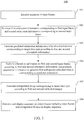
- FIG. 3 is a flow chart of a frame rendering method 300 in an embodiment of the present invention.
- the frame rendering method 300 can be used in the frame rendering apparatus 100 illustrated in FIG. 1 . More specifically, in an embodiment, the computer-executable instructions 100 operate as the frame rendering apparatus 100 when being executed by the processing module 106 to perform the frame rendering method 300.
- FIG. 4 is a diagram illustrating the objects and the actions within the process of the frame rendering method 300 in an embodiment of the present invention.
- the frame rendering method 300 includes the steps outlined below (The steps are not recited in the sequence in which the steps are performed. That is, unless the sequence of the steps is expressly indicated, the sequence of the steps is interchangeable, and all or part of the steps may be simultaneously, partially simultaneously, or sequentially performed).
- step 301 the sequence of input frames Fin are received, in which two consecutive input frames F1 and F2 are illustrated in blocks 401 and 402 respectively in FIG. 4 .
- step 302 first orientation information O1 corresponding to the first input frame F1 and second orientation information O2 corresponding to the second input frame F2 are retrieved from the motion sensor 104.
- the first orientation information O1 includes the information of the orientation of the head-mounted device 1 corresponding to the first input frame F1, i.e. corresponding to the first time spot t-3T, detected by the motion sensor 104.
- the second orientation information O2 includes the information of the orientation of the head-mounted device 1 corresponding to the second input frame F2, i.e. corresponding to the second time spot t-T, detected by the motion sensor 104.
- step 303 predicted orientation information (not illustrated) of a predicted orientation corresponding to the target time spot t is generated according to the first orientation information O1 and the second orientation information O2.
- a moving trajectory of the head-mounted device 1 between the first time spot t-3T and the second time spot t-T can be calculated according to the first orientation information O1 and the second orientation information O2.
- the predicted orientation information can be obtained by using extrapolation based on the moving trajectory.
- step 304 orientation calibration, illustrated as block 403 in FIG. 4 , is performed on the first input frame F1 according to the first orientation information O1 and the predicted orientation information to generate a first calibrated frame F1' corresponding to the predicted orientation, illustrated as block 404 in FIG. 4 .
- the orientation calibration is performed on the second input frame F2 according to the second orientation information O2 and the predicted orientation information to generate a second calibrated frame F2', illustrated as block 405 in FIG. 4 , corresponding to the predicted orientation.
- a predicted model-view-projection (MVP) matrix can be obtained according to the predicted orientation information.
- first input frame F1 is projected to a world space by multiplying the first input frame F1 by an inverse of the MVP matrix corresponding to the first time spot t-3T.
- the projected first input frame is further projected to a screen space by multiplying the projected first input frame by the predicted MVP matrix to generate the first calibrated frame.
- the second input frame F2 is projected to the world space by multiplying the second input frame F2 by the inverse of the MVP matrix corresponding to the second time spot t-T.
- the projected second input frame is further projected to the screen space by multiplying the projected second input frame by the predicted MVP matrix to generate the second calibrated frame.
- the orientation of the first input frame F1 and the second input frame F2 can be calibrated to be aligned with the predicted orientation.
- step 305 one of the extrapolated frames Fex corresponding to the target time spot t, illustrated as block 411 in FIG. 4 , is generated according to the first calibrated frame F1' and the second calibrated frame F2'.
- a background detection is performed according to the first calibrated frame F1' and the second calibrated frame F2' to generate a background mask illustrated as block 407 in FIG. 4 .
- a background mask illustrated as block 407 in FIG. 4 .
- a motion estimation is performed between the first calibrated frame F1' and the second calibrated frame F2' to generate a motion vector table, illustrated as block 409 in FIG. 4 .
- the motion estimation 408 is performed based on the background mask 407. Due to the background mask 407 generated previously, unmoved pixels in the first calibrated frame F1' and the second calibrated frame F2' can be neglected to save the computation resource.
- the motion vector table 409 includes the motion vectors of the foreground objects in the first calibrated frame F1' and the second calibrated frame F2'.
- a frame extrapolation is performed according to the first calibrated frame F1' and the second calibrated frame F2' based on the motion vector table 409 to generate the extrapolated frame Fe.
- step 306 the sequence of output frames Fout including the input frames Fin and the extrapolated frames Fe are generated and displayed on the display apparatus 150.
- the frame rendering apparatus 100 and the frame rendering method 300 in the present invention can accomplish a high frame rate display result by performing preprocessing before the frames are displayed. Additional hardware cost is thus avoided.
- the frame rendering method 300 may be implemented as a computer program.
- this executing device performs the frame rendering method 300.
- the computer program can be stored in a non-transitory computer readable storage medium such as a ROM (read-only memory), a flash memory, a floppy disk, a hard disk, an optical disc, a flash disk, a flash drive, a tape, a database accessible from a network, or any storage medium with the same functionality that can be contemplated by persons of ordinary skill in the art to which this disclosure pertains.
Landscapes
- Engineering & Computer Science (AREA)
- Theoretical Computer Science (AREA)
- Physics & Mathematics (AREA)
- General Physics & Mathematics (AREA)
- General Engineering & Computer Science (AREA)
- Human Computer Interaction (AREA)
- Computer Hardware Design (AREA)
- Computer Vision & Pattern Recognition (AREA)
- Computer Graphics (AREA)
- Software Systems (AREA)
- Multimedia (AREA)
- Processing Or Creating Images (AREA)
- Controls And Circuits For Display Device (AREA)
Abstract
Description
- This application claims priority to
US Provisional Application Serial Number 62/554,526, filed September 05, 2017 - The present invention relates to a frame rendering technology. More particularly, the present invention relates to a frame rendering apparatus and a frame rendering method.
- In recent years, virtual reality technology is widely used in the fields such as gaming, engineering and military, etc. In order to experience the virtual reality environment, a user needs to view the displayed frames through the display apparatus disposed at such as, but not limited a head-mounted device wear by the user. However, high frame rate is important to achieve a fluent experience without motion sickness. In conventional technology, top-tier hardware setup is required to accomplish the desired fluency, which results in greater hardware cost.
- Accordingly, what is needed is a frame rendering apparatus and a frame rendering method to address the issues mentioned above.
- An aspect of the present invention is to provide a frame rendering method used in a head-mounted device that includes the steps outlined below. A sequence of input frames are received. For each two of the consecutive input frames that include a first input frame corresponding to a first time spot and a second input frame next to the first frame and corresponding to a second time spot, the steps outlined below are performed. First orientation information corresponding to the first input frame and second orientation information corresponding to the second input frame are retrieved from a motion sensor of the head-mounted device. Predicted orientation information of a predicted orientation corresponding to a target time spot is generated according to the first orientation information and the second orientation information, wherein the target time spot is between the second time spot and a third time spot of a third input frame next to the second input frame. Orientation calibration is performed on the first input frame according to the first orientation information to generate a first calibrated frame corresponding to the predicted orientation and the orientation calibration is performed on the second input frame according to the second orientation information to generate a second calibrated frame corresponding to the predicted orientation. One of a plurality of extrapolated frames corresponding to the target time spot is generated according to the first calibrated frame and the second calibrated frame.
- Another aspect of the present invention is to provide a frame rendering apparatus used in a head-mounted device. The frame rendering apparatus includes a storage module, a motion sensor and a processing module. The storage module is configured to store a plurality of computer-executable instructions. The processing module is electrically coupled to the storage module and the motion sensor and is configured to retrieve and execute the computer-executable instructions to perform a frame rendering method when the computer-executable instructions are executed. The frame rendering method includes the steps outlined below. A sequence of input frames are received. For each two of the consecutive input frames that include a first input frame corresponding to a first time spot and a second input frame next to the first frame and corresponding to a second time spot, the steps outlined below are performed. First orientation information corresponding to the first input frame and second orientation information corresponding to the second input frame are retrieved from the motion sensor. Predicted orientation information of a predicted orientation corresponding to a target time spot is generated according to the first orientation information and the second orientation information, wherein the target time spot is between the second time spot and a third time spot of a third input frame second input frame. Orientation calibration is performed on the first input frame according to the first orientation information and the predicted orientation information to generate a first calibrated frame corresponding to the predicted orientation and the orientation calibration is performed on the second input frame according to the second orientation information and the predicted orientation information to generate a second calibrated frame corresponding to the predicted orientation. One of a plurality of extrapolated frames corresponding to the target time spot is generated according to the first calibrated frame and the second calibrated frame.
- Yet another aspect of the present invention is to provide a non-transitory computer readable storage medium that stores a computer program including a plurality of computer-executable instructions to perform a frame rendering method used in a frame rendering apparatus used in a head-mounted device, the frame rendering apparatus at least includes a storage module, a motion sensor and a processing module electrically coupled to the storage module and the motion sensor and configured to retrieve and execute the computer-executable instructions to perform a frame rendering method when the computer-executable instructions are executed. The frame rendering method includes the steps outlined below. A sequence of input frames are received. For each two of the consecutive input frames that include a first input frame corresponding to a first time spot and a second input frame next to the first frame and corresponding to a second time spot, the steps outlined below are performed. First orientation information corresponding to the first input frame and second orientation information corresponding to the second input frame are retrieved from the motion sensor. Predicted orientation information of a predicted orientation corresponding to a target time spot is generated according to the first orientation information and the second orientation information, wherein the target time spot is between the second time spot and a third time spot of a third input frame second input frame. Orientation calibration is performed on the first input frame according to the first orientation information and the predicted orientation information to generate a first calibrated frame corresponding to the predicted orientation and the orientation calibration is performed on the second input frame according to the second orientation information and the predicted orientation information to generate a second calibrated frame corresponding to the predicted orientation. One of a plurality of extrapolated frames corresponding to the target time spot is generated according to the first calibrated frame and the second calibrated frame.
- These and other features, aspects, and advantages of the present invention will become better understood with reference to the following description and appended claims.
- It is to be understood that both the foregoing general description and the following detailed description are by examples, and are intended to provide further explanation of the invention as claimed.
- The invention can be more fully understood by reading the following detailed description of the embodiment, with reference made to the accompanying drawings as follows:
-
FIG. 1 is a block diagram of a head-mounted device in an embodiment of the present invention; -
FIG. 2 is a timing diagram of the input frames and the extrapolated frames in an embodiment of the present invention; -
FIG. 3 is a flow chart of a frame rendering method in an embodiment of the present invention; and -
FIG. 4 is a diagram illustrating the objects and the actions within the process of the frame rendering method in an embodiment of the present invention. - Reference will now be made in detail to the present embodiments of the disclosure, examples of which are illustrated in the accompanying drawings. Wherever possible, the same reference numbers are used in the drawings and the description to refer to the same or like parts.
- Any element in a claim that does not explicitly state "means for" performing a specified function, or "step for" performing a specific function, is not to be interpreted as a "means" or "step" clause as specified in 35 U.S.C. § 112(f). In particular, the use of "step of' in the claims herein is not intended to invoke the provisions of 35 U.S.C. § 112(f).
- Reference is now made to
FIG. 1. FIG. 1 is a block diagram of a head-mounteddevice 1 in an embodiment of the present invention. - In an embodiment, the head-mounted
device 1 includes a frame rendering apparatus 100 and adisplay apparatus 150. The head-mounteddevice 1 can be wear by a user. More specifically, in an embodiment, the frame rendering apparatus 100 is configured to receive and perform frame rendering on a sequence of input frames Fin to generate a sequence of output frames Fout. Further, thedisplay apparatus 150 is configured to display the output frames Fout for the user to perceive. - By performing frame rendering of the input frames Fin, a high frame-rate of the displayed frames can be obtained such that the user using the head-mounted
device 1 can have a better virtual reality experience. - The frame rendering apparatus 100 includes a
storage module 102, amotion sensor 104 and aprocessing module 106. - In an embodiment, the
storage module 102 can be such as, but not limited to CD ROM, RAM, ROM, floppy disk, hard disk or optic magnetic disk. Thestorage module 102 is configured to store a plurality of computer-executable instructions 101. - The
motion sensor 104 is configured to detect orientation information of the head-mounteddevice 1. In an embodiment, themotion sensor 104 is such as, but not limited to a G sensor. It is appreciated that in different embodiments, the number of themotion sensor 104 can be one or more than one. The present invention is not limited thereto. - The
processing module 106 is electrically coupled to thestorage module 102 and themotion sensor 104. In an embodiment, theprocessing module 106 is configured to retrieve and execute the computer-executable instructions 101 to operate the function of the frame rendering apparatus 100 accordingly. - In an embodiment, the
processing module 106 receives input frames Fin to perform frame rendering thereon. - More specifically, the
processing module 106 performs frame rendering on each two of the consecutive input frames in the received sequence of input frames Fin, in which the two consecutive input frames include a first input frame corresponding to a first time spot and a second input frame corresponding to a second time spot next to the first time spot. The frame rendering result, which includes one of a plurality extrapolated frames, is generated at a target time spot. - Consequently, a plurality of extrapolated frames each corresponding to two of the consecutive input frames are generated.
- Reference is now made to
FIG. 2. FIG. 2 is a timing diagram of the input frames Fin and the extrapolated frames Fex in an embodiment of the present invention. - In an embodiment, for one of the extrapolated frames Fex, which is the extrapolated frame Fe, the target time spot is t. In order to generate the extrapolated frame Fe, two consecutive input frames that include the first input frame F1 corresponding to a first time spot and a second input frame F2 corresponding to a second time spot next to the first time spot.
- In an embodiment, the target time spot t is between the second time spot and a third time spot of a third input frame F3 next to the second input frame F2. In an embodiment, the first time spot is t-3T, the second time spot is t-T and the third time spot is t+T, in which T is half of the time period between each two of the consecutive input frames. In other words, 2T is the time period between each two of the consecutive input frames, also is an inverse of the frame rate of the input frames Fin.
- In an embodiment, after performing frame rendering, the
processing module 106 displays the output frames Fout that includes the input frames Fin and the extrapolated frames Fex on thedisplay apparatus 150. The user wearing the head-mounteddevice 1 can thus perceive the displayed frames with high frame-rate. - Reference is now made to
FIG. 3 andFIG. 4 at the same time. The detail of the operation of the frame rendering apparatus 100 is described in the following paragraphs in accompany withFIG. 3 andFIG. 4 . -
FIG. 3 is a flow chart of aframe rendering method 300 in an embodiment of the present invention. Theframe rendering method 300 can be used in the frame rendering apparatus 100 illustrated inFIG. 1 . More specifically, in an embodiment, the computer-executable instructions 100 operate as the frame rendering apparatus 100 when being executed by theprocessing module 106 to perform theframe rendering method 300. -
FIG. 4 is a diagram illustrating the objects and the actions within the process of theframe rendering method 300 in an embodiment of the present invention. - The
frame rendering method 300 includes the steps outlined below (The steps are not recited in the sequence in which the steps are performed. That is, unless the sequence of the steps is expressly indicated, the sequence of the steps is interchangeable, and all or part of the steps may be simultaneously, partially simultaneously, or sequentially performed). - In
step 301, the sequence of input frames Fin are received, in which two consecutive input frames F1 and F2 are illustrated inblocks FIG. 4 . - In
step 302, first orientation information O1 corresponding to the first input frame F1 and second orientation information O2 corresponding to the second input frame F2 are retrieved from themotion sensor 104. - In an embodiment, the first orientation information O1 includes the information of the orientation of the head-mounted
device 1 corresponding to the first input frame F1, i.e. corresponding to the first time spot t-3T, detected by themotion sensor 104. - The second orientation information O2 includes the information of the orientation of the head-mounted
device 1 corresponding to the second input frame F2, i.e. corresponding to the second time spot t-T, detected by themotion sensor 104. - In
step 303, predicted orientation information (not illustrated) of a predicted orientation corresponding to the target time spot t is generated according to the first orientation information O1 and the second orientation information O2. - In an embodiment, a moving trajectory of the head-mounted
device 1 between the first time spot t-3T and the second time spot t-T can be calculated according to the first orientation information O1 and the second orientation information O2. As a result, the predicted orientation information can be obtained by using extrapolation based on the moving trajectory. - In
step 304, orientation calibration, illustrated asblock 403 inFIG. 4 , is performed on the first input frame F1 according to the first orientation information O1 and the predicted orientation information to generate a first calibrated frame F1' corresponding to the predicted orientation, illustrated asblock 404 inFIG. 4 . The orientation calibration is performed on the second input frame F2 according to the second orientation information O2 and the predicted orientation information to generate a second calibrated frame F2', illustrated asblock 405 inFIG. 4 , corresponding to the predicted orientation. - In an embodiment, a predicted model-view-projection (MVP) matrix can be obtained according to the predicted orientation information.
- Further, the first input frame F1 is projected to a world space by multiplying the first input frame F1 by an inverse of the MVP matrix corresponding to the first time spot t-3T. The projected first input frame is further projected to a screen space by multiplying the projected first input frame by the predicted MVP matrix to generate the first calibrated frame.
- Similarly, the second input frame F2 is projected to the world space by multiplying the second input frame F2 by the inverse of the MVP matrix corresponding to the second time spot t-T. The projected second input frame is further projected to the screen space by multiplying the projected second input frame by the predicted MVP matrix to generate the second calibrated frame.
- As a result, by performing the orientation calibration, the orientation of the first input frame F1 and the second input frame F2 can be calibrated to be aligned with the predicted orientation.
- In
step 305, one of the extrapolated frames Fex corresponding to the target time spot t, illustrated as block 411 inFIG. 4 , is generated according to the first calibrated frame F1' and the second calibrated frame F2'. - In an embodiment, a background detection, illustrated as
block 406 inFIG. 4 , is performed according to the first calibrated frame F1' and the second calibrated frame F2' to generate a background mask illustrated asblock 407 inFIG. 4 . As a result, the objects in the foreground and the objects in the background of the first calibrated frame F1' and the second calibrated frame F2' can be distinguished. The background objects can thus be masked. - Subsequently, a motion estimation, illustrated as
block 408 inFIG. 4 , is performed between the first calibrated frame F1' and the second calibrated frame F2' to generate a motion vector table, illustrated asblock 409 inFIG. 4 . In an embodiment, themotion estimation 408 is performed based on thebackground mask 407. Due to thebackground mask 407 generated previously, unmoved pixels in the first calibrated frame F1' and the second calibrated frame F2' can be neglected to save the computation resource. - As a result, in an embodiment, the motion vector table 409 includes the motion vectors of the foreground objects in the first calibrated frame F1' and the second calibrated frame F2'.
- Moreover, a frame extrapolation, illustrated as
block 410 inFIG. 4 , is performed according to the first calibrated frame F1' and the second calibrated frame F2' based on the motion vector table 409 to generate the extrapolated frame Fe. - In
step 306, the sequence of output frames Fout including the input frames Fin and the extrapolated frames Fe are generated and displayed on thedisplay apparatus 150. - The frame rendering apparatus 100 and the
frame rendering method 300 in the present invention can accomplish a high frame rate display result by performing preprocessing before the frames are displayed. Additional hardware cost is thus avoided. - It should be noted that, in some embodiments, the
frame rendering method 300 may be implemented as a computer program. When the computer program is executed by a computer, an electronic device, or theprocessing module 106 inFig. 1 , this executing device performs theframe rendering method 300. The computer program can be stored in a non-transitory computer readable storage medium such as a ROM (read-only memory), a flash memory, a floppy disk, a hard disk, an optical disc, a flash disk, a flash drive, a tape, a database accessible from a network, or any storage medium with the same functionality that can be contemplated by persons of ordinary skill in the art to which this disclosure pertains. - It will be apparent to those skilled in the art that various modifications and variations can be made to the structure of the present invention without departing from the scope or spirit of the invention. In view of the foregoing, it is intended that the present invention cover modifications and variations of this invention provided they fall within the scope of the following claims.
Claims (15)
- A frame rendering method used in a head-mounted device comprising:receiving a sequence of input frames;for each two of the consecutive input frames that comprises a first input frame corresponding to a first time spot and a second input frame next to the first frame and corresponding to a second time spot, performing the steps of:retrieving first orientation information corresponding to the first input frame and second orientation information corresponding to the second input frame from a motion sensor of the head-mounted device;generating predicted orientation information of a predicted orientation corresponding to a target time spot according to the first orientation information and the second orientation information, wherein the target time spot is between the second time spot and a third time spot of a third input frame next to the second input frame;performing orientation calibration on the first input frame according to the first orientation information and the predicted orientation information to generate a first calibrated frame corresponding to the predicted orientation, and performing orientation calibration on the second input frame according to the second orientation information and the predicted orientation information to generate a second calibrated frame corresponding to the predicted orientation; andgenerating one of a plurality of extrapolated frames corresponding to the target time spot according to the first calibrated frame and the second calibrated frame.
- The frame rendering method of claim 1, wherein the step of generating the extrapolated frames further comprises:performing a motion estimation between the first calibrated frame and the second calibrated frame to generate a motion vector table; andperforming a frame extrapolation according to the first calibrated frame and the second calibrated frame based on the motion vector table to generate the one of the extrapolated frames.
- The frame rendering method of claim 2, wherein before the step of performing the motion estimation further comprises:performing a background detection according to the first calibrated frame and the second calibrated frame to generate a background mask;wherein the motion estimation is performed between the first calibrated frame and the second calibrated frame based on the background mask to neglect unmoved pixels in the first calibrated frame and the second calibrated frame.
- The frame rendering method of claim 1, wherein the target time spot is t, the first time spot is t-3T, the second time spot is t-T and the third time spot is t+T, wherein T is a time period between each two of the consecutive input frames.
- The frame rendering method of claim 1, wherein the step of performing orientation calibration on the first input frame and the second input frame further comprises:obtaining a predicted model-view-projection (MVP) matrix according to the predicted orientation information;projecting the first input frame to a world space by multiplying the first input frame by an inverse of the MVP matrix corresponding to the first time spot and further projecting the projected first input frame to a screen space by multiplying the projected first input frame by the predicted MVP matrix to generate the first calibrated frame; andprojecting the second input frame to the world space by multiplying the second input frame by the inverse of the MVP matrix corresponding to the second time spot and further projecting the projected second input frame to the screen space by multiplying the projected second input frame by the predicted MVP matrix to generate the second calibrated frame.
- The frame rendering method of claim 1, further comprising:generating a sequence of output frames comprising the input frames and the extrapolated frames; anddisplaying the output frames on a display apparatus of the head-mounted device.
- A frame rendering apparatus used in a head-mounted device comprising:a storage module configured to store a plurality of computer-executable instructions;a motion sensor; anda processing module electrically coupled to the storage module and the motion sensor and configured to retrieve and execute the computer-executable instructions to perform a frame rendering method when the computer-executable instructions are executed, wherein the frame rendering method comprises:receiving a sequence of input frames;for each two of the consecutive input frames that comprises a first input frame corresponding to a first time spot and a second input frame next to the first frame and corresponding to a second time spot, performing the steps of:retrieving first orientation information corresponding to the first input frame and second orientation information corresponding to the second input frame from the motion sensor;generating predicted orientation information of a predicted orientation corresponding to a target time spot according to the first orientation information and the second orientation information, wherein the target time spot is between the second time spot and a third time spot of a third input frame next to the second input frame;performing orientation calibration on the first input frame according to the first orientation information and the predicted orientation information to generate a first calibrated frame corresponding to the predicted orientation and performing orientation calibration on the second input frame according to the second orientation information and the predicted orientation information to generate a second calibrated frame corresponding to the predicted orientation; andgenerating one of a plurality of extrapolated frames corresponding to the target time spot according to the first calibrated frame and the second calibrated frame.
- The frame rendering apparatus of claim 1, wherein the step of generating the extrapolated frames further comprises:performing a motion estimation between the first calibrated frame and the second calibrated frame to generate a motion vector table; andperforming a frame extrapolation according to the first calibrated frame and the second calibrated frame based on the motion vector table to generate the one of the extrapolated frames.
- The frame rendering apparatus of claim 8, wherein before the step of performing the motion estimation further comprises:performing a background detection according to the first calibrated frame and the second calibrated frame to generate a background mask;wherein the motion estimation is performed between the first calibrated frame and the second calibrated frame based on the background mask to neglect unmoved pixels in the first calibrated frame and the second calibrated frame.
- The frame rendering apparatus of claim 7, wherein the target time spot is t, the first time spot is t-3T, the second time spot is t-T and the third time spot is t+T, wherein T is a time period between each two of the consecutive input frames.
- The frame rendering apparatus of claim 7, wherein the step of performing orientation calibration on the first input frame and the second input frame further comprises:obtaining a predicted MVP matrix according to the predicted orientation information;projecting the first input frame to a world space by multiplying the first input frame by an inverse of the MVP matrix corresponding to the first time spot and further projecting the projected first input frame to a screen space by multiplying the projected first input frame by the predicted MVP matrix to generate the first calibrated frame; andprojecting the second input frame to the world space by multiplying the second input frame by the inverse of the MVP matrix corresponding to the second time spot and further projecting the projected second input frame to the screen space by multiplying the projected second input frame by the predicted MVP matrix to generate the second calibrated frame.
- The frame rendering apparatus of claim 7, wherein the frame rendering method further comprises:generating a sequence of output frames comprising the input frames and the extrapolated frames; anddisplaying the output frames on a display apparatus of the head-mounted device.
- A non-transitory computer readable storage medium that stores a computer program comprising a plurality of computer-executable instructions to perform a frame rendering method used in a frame rendering apparatus used in a head-mounted device, the frame rendering apparatus at least comprises a storage module, a motion sensor and a processing module electrically coupled to the storage module and the motion sensor and configured to retrieve and execute the computer-executable instructions to perform a frame rendering method when the computer-executable instructions are executed, wherein the frame rendering method comprises:receiving a sequence of input frames;for each two of the consecutive input frames that comprises a first input frame corresponding to a first time spot and a second input frame next to the first frame and corresponding to a second time spot, performing the steps of:retrieving first orientation information corresponding to the first input frame and second orientation information corresponding to the second input frame from the motion sensor;generating predicted orientation information of a predicted orientation corresponding to a target time spot according to the first orientation information and the second orientation information, wherein the target time spot is between the second time spot and a third time spot of a third input frame next to the second input frame;performing orientation calibration on the first input frame according to the first orientation information and the predicted orientation information to generate a first calibrated frame corresponding to the predicted orientation and performing orientation calibration on the second input frame according to the second orientation information and the predicted orientation information to generate a second calibrated frame corresponding to the predicted orientation; andgenerating one of a plurality of extrapolated frames corresponding to the target time spot according to the first calibrated frame and the second calibrated frame.
- The non-transitory computer readable storage medium of claim 13, wherein the step of generating the extrapolated frames further comprises:performing a motion estimation between the first calibrated frame and the second calibrated frame to generate a motion vector table; andperforming a frame extrapolation according to the first calibrated frame and the second calibrated frame based on the motion vector table to generate the one of the extrapolated frames.
- The non-transitory computer readable storage medium of claim 13, wherein before the step of performing the motion estimation further comprises:performing a background detection according to the first calibrated frame and the second calibrated frame to generate a background mask;wherein the motion estimation is performed between the first calibrated frame and the second calibrated frame based on the background mask to neglect unmoved pixels in the first calibrated frame and the second calibrated frame.
Applications Claiming Priority (1)
| Application Number | Priority Date | Filing Date | Title |
|---|---|---|---|
| US201762554526P | 2017-09-05 | 2017-09-05 |
Publications (2)
| Publication Number | Publication Date |
|---|---|
| EP3451127A1 true EP3451127A1 (en) | 2019-03-06 |
| EP3451127B1 EP3451127B1 (en) | 2020-10-21 |
Family
ID=63528521
Family Applications (1)
| Application Number | Title | Priority Date | Filing Date |
|---|---|---|---|
| EP18192590.0A Active EP3451127B1 (en) | 2017-09-05 | 2018-09-04 | Frame rendering apparatus, method and non-transitory computer readable storage medium |
Country Status (4)
| Country | Link |
|---|---|
| US (1) | US10628958B2 (en) |
| EP (1) | EP3451127B1 (en) |
| CN (1) | CN109448085B (en) |
| TW (1) | TWI691935B (en) |
Families Citing this family (5)
| Publication number | Priority date | Publication date | Assignee | Title |
|---|---|---|---|---|
| TWI778785B (en) * | 2021-02-26 | 2022-09-21 | 明俐科技有限公司 | Correcting device and correcting method of real-time image |
| US20230136662A1 (en) * | 2021-10-27 | 2023-05-04 | Meta Platforms Technologies, Llc | Parallax Asynchronous Spacewarp for Multiple Frame Extrapolation |
| US20240212225A1 (en) * | 2022-12-27 | 2024-06-27 | Htc Corporation | Immersive content displaying method, display device and non-transitory computer readable storage medium |
| US20240311951A1 (en) * | 2023-03-16 | 2024-09-19 | Intel Corporation | Dynamic gpu frame generation and read/write scaling using command buffer predication |
| CN121126026B (en) * | 2024-06-05 | 2026-08-11 | 荣耀终端股份有限公司 | A frame interpolation method, apparatus, and storage medium |
Citations (2)
| Publication number | Priority date | Publication date | Assignee | Title |
|---|---|---|---|---|
| US20110261264A1 (en) * | 2008-12-24 | 2011-10-27 | Baham Zafarifar | Image Processing |
| US20170213388A1 (en) * | 2016-01-25 | 2017-07-27 | Jeffrey Neil Margolis | Frame Projection For Augmented Reality Environments |
Family Cites Families (9)
| Publication number | Priority date | Publication date | Assignee | Title |
|---|---|---|---|---|
| US8223831B2 (en) * | 2007-06-22 | 2012-07-17 | Samsung Electronics Co., Ltd. | System and method for periodic pattern detection for motion compensated interpolation |
| US8660175B2 (en) * | 2007-12-10 | 2014-02-25 | Qualcomm Incorporated | Selective display of interpolated or extrapolated video units |
| US9262950B2 (en) * | 2011-04-20 | 2016-02-16 | Microsoft Technology Licensing, Llc | Augmented reality extrapolation techniques |
| JP6405092B2 (en) * | 2014-01-28 | 2018-10-17 | キヤノン株式会社 | Image generating apparatus and image generating method |
| US10310595B2 (en) * | 2014-06-30 | 2019-06-04 | Sony Corporation | Information processing apparatus, information processing method, computer program, and image processing system |
| US10684485B2 (en) * | 2015-03-06 | 2020-06-16 | Sony Interactive Entertainment Inc. | Tracking system for head mounted display |
| CN104952101B (en) * | 2015-05-21 | 2017-12-05 | 中国人民解放军理工大学 | A kind of motion vector rendering intent based on height field |
| JP2017111164A (en) * | 2015-12-14 | 2017-06-22 | 株式会社リコー | Image projection device, and interactive input/output system |
| US10890966B2 (en) * | 2017-07-27 | 2021-01-12 | Arm Limited | Graphics processing systems |
-
2018
- 2018-08-30 US US16/118,421 patent/US10628958B2/en active Active
- 2018-09-04 CN CN201811026634.9A patent/CN109448085B/en active Active
- 2018-09-04 EP EP18192590.0A patent/EP3451127B1/en active Active
- 2018-09-04 TW TW107131026A patent/TWI691935B/en active
Patent Citations (2)
| Publication number | Priority date | Publication date | Assignee | Title |
|---|---|---|---|---|
| US20110261264A1 (en) * | 2008-12-24 | 2011-10-27 | Baham Zafarifar | Image Processing |
| US20170213388A1 (en) * | 2016-01-25 | 2017-07-27 | Jeffrey Neil Margolis | Frame Projection For Augmented Reality Environments |
Also Published As
| Publication number | Publication date |
|---|---|
| TW201921319A (en) | 2019-06-01 |
| EP3451127B1 (en) | 2020-10-21 |
| TWI691935B (en) | 2020-04-21 |
| CN109448085A (en) | 2019-03-08 |
| CN109448085B (en) | 2023-02-28 |
| US10628958B2 (en) | 2020-04-21 |
| US20190073786A1 (en) | 2019-03-07 |
Similar Documents
| Publication | Publication Date | Title |
|---|---|---|
| US10628958B2 (en) | Frame rendering apparatus, method and non-transitory computer readable storage medium | |
| JP7165731B2 (en) | Target detection method and device, training method, electronic device and medium | |
| US10701433B2 (en) | Rendering of user-defined message having 3D motion information | |
| US7899122B2 (en) | Method, apparatus and computer program product for generating interpolation frame | |
| US20100302249A1 (en) | Apparatus, systems and methods for layout of scene graphs using node bounding areas | |
| US10319081B2 (en) | Distortion rectification method and terminal | |
| US9704271B2 (en) | Method and apparatus for image blurring | |
| US20170163958A1 (en) | Method and device for image rendering processing | |
| JP2018537748A (en) | Light field rendering of images with variable computational complexity | |
| KR20160074194A (en) | Electronic device and method for controlling display of a screen | |
| US10789987B2 (en) | Accessing a video segment | |
| US20050134591A1 (en) | Spatio-temporal generation of motion blur | |
| CN110874853A (en) | Method, device and equipment for determining target motion and storage medium | |
| US10742952B2 (en) | Three dimensional reconstruction method, apparatus and non-transitory computer readable storage medium thereof | |
| CN113657518A (en) | Training method, target image detection method, device, electronic device, and medium | |
| JP2020028096A (en) | Image processing apparatus, control method for image processing apparatus, and program | |
| CN109885369B (en) | Image linkage method and device | |
| CN115134677A (en) | Video cover selection method and device, electronic equipment and computer storage medium | |
| CN117632069A (en) | Image display method, device and virtual reality equipment | |
| CN115617238A (en) | Screen capture method and device | |
| US20150254043A1 (en) | Display property determination | |
| CN118052689A (en) | A method, device and equipment for generating a thermal map | |
| Motter et al. | Relativistic invariance of Lyapunov exponents in bounded and unbounded systems | |
| US10192529B2 (en) | Electronic apparatus, frames per second decision method, and non-transitory computer readable storage medium thereof | |
| US10311607B2 (en) | Chart decomposition and sequencing for limited display devices |
Legal Events
| Date | Code | Title | Description |
|---|---|---|---|
| PUAI | Public reference made under article 153(3) epc to a published international application that has entered the european phase |
Free format text: ORIGINAL CODE: 0009012 |
|
| STAA | Information on the status of an ep patent application or granted ep patent |
Free format text: STATUS: EXAMINATION IS IN PROGRESS |
|
| 17P | Request for examination filed |
Effective date: 20180904 |
|
| AK | Designated contracting states |
Kind code of ref document: A1 Designated state(s): AL AT BE BG CH CY CZ DE DK EE ES FI FR GB GR HR HU IE IS IT LI LT LU LV MC MK MT NL NO PL PT RO RS SE SI SK SM TR |
|
| AX | Request for extension of the european patent |
Extension state: BA ME |
|
| RBV | Designated contracting states (corrected) |
Designated state(s): AL AT BE BG CH CY CZ DE DK EE ES FI FR GB GR HR HU IE IS IT LI LT LU LV MC MK MT NL NO PL PT RO RS SE SI SK SM TR |
|
| GRAP | Despatch of communication of intention to grant a patent |
Free format text: ORIGINAL CODE: EPIDOSNIGR1 |
|
| STAA | Information on the status of an ep patent application or granted ep patent |
Free format text: STATUS: GRANT OF PATENT IS INTENDED |
|
| RIC1 | Information provided on ipc code assigned before grant |
Ipc: G06F 3/147 20060101ALI20200305BHEP Ipc: G09G 5/395 20060101ALI20200305BHEP Ipc: G06F 3/01 20060101AFI20200305BHEP |
|
| INTG | Intention to grant announced |
Effective date: 20200406 |
|
| GRAS | Grant fee paid |
Free format text: ORIGINAL CODE: EPIDOSNIGR3 |
|
| GRAA | (expected) grant |
Free format text: ORIGINAL CODE: 0009210 |
|
| STAA | Information on the status of an ep patent application or granted ep patent |
Free format text: STATUS: THE PATENT HAS BEEN GRANTED |
|
| AK | Designated contracting states |
Kind code of ref document: B1 Designated state(s): AL AT BE BG CH CY CZ DE DK EE ES FI FR GB GR HR HU IE IS IT LI LT LU LV MC MK MT NL NO PL PT RO RS SE SI SK SM TR |
|
| REG | Reference to a national code |
Ref country code: GB Ref legal event code: FG4D |
|
| REG | Reference to a national code |
Ref country code: CH Ref legal event code: EP |
|
| REG | Reference to a national code |
Ref country code: IE Ref legal event code: FG4D |
|
| REG | Reference to a national code |
Ref country code: DE Ref legal event code: R096 Ref document number: 602018008876 Country of ref document: DE |
|
| REG | Reference to a national code |
Ref country code: AT Ref legal event code: REF Ref document number: 1326474 Country of ref document: AT Kind code of ref document: T Effective date: 20201115 |
|
| REG | Reference to a national code |
Ref country code: AT Ref legal event code: MK05 Ref document number: 1326474 Country of ref document: AT Kind code of ref document: T Effective date: 20201021 |
|
| PG25 | Lapsed in a contracting state [announced via postgrant information from national office to epo] |
Ref country code: PT Free format text: LAPSE BECAUSE OF FAILURE TO SUBMIT A TRANSLATION OF THE DESCRIPTION OR TO PAY THE FEE WITHIN THE PRESCRIBED TIME-LIMIT Effective date: 20210222 Ref country code: RS Free format text: LAPSE BECAUSE OF FAILURE TO SUBMIT A TRANSLATION OF THE DESCRIPTION OR TO PAY THE FEE WITHIN THE PRESCRIBED TIME-LIMIT Effective date: 20201021 Ref country code: FI Free format text: LAPSE BECAUSE OF FAILURE TO SUBMIT A TRANSLATION OF THE DESCRIPTION OR TO PAY THE FEE WITHIN THE PRESCRIBED TIME-LIMIT Effective date: 20201021 Ref country code: NO Free format text: LAPSE BECAUSE OF FAILURE TO SUBMIT A TRANSLATION OF THE DESCRIPTION OR TO PAY THE FEE WITHIN THE PRESCRIBED TIME-LIMIT Effective date: 20210121 Ref country code: GR Free format text: LAPSE BECAUSE OF FAILURE TO SUBMIT A TRANSLATION OF THE DESCRIPTION OR TO PAY THE FEE WITHIN THE PRESCRIBED TIME-LIMIT Effective date: 20210122 |
|
| REG | Reference to a national code |
Ref country code: LT Ref legal event code: MG4D |
|
| PG25 | Lapsed in a contracting state [announced via postgrant information from national office to epo] |
Ref country code: ES Free format text: LAPSE BECAUSE OF FAILURE TO SUBMIT A TRANSLATION OF THE DESCRIPTION OR TO PAY THE FEE WITHIN THE PRESCRIBED TIME-LIMIT Effective date: 20201021 Ref country code: AT Free format text: LAPSE BECAUSE OF FAILURE TO SUBMIT A TRANSLATION OF THE DESCRIPTION OR TO PAY THE FEE WITHIN THE PRESCRIBED TIME-LIMIT Effective date: 20201021 Ref country code: BG Free format text: LAPSE BECAUSE OF FAILURE TO SUBMIT A TRANSLATION OF THE DESCRIPTION OR TO PAY THE FEE WITHIN THE PRESCRIBED TIME-LIMIT Effective date: 20210121 Ref country code: PL Free format text: LAPSE BECAUSE OF FAILURE TO SUBMIT A TRANSLATION OF THE DESCRIPTION OR TO PAY THE FEE WITHIN THE PRESCRIBED TIME-LIMIT Effective date: 20201021 Ref country code: IS Free format text: LAPSE BECAUSE OF FAILURE TO SUBMIT A TRANSLATION OF THE DESCRIPTION OR TO PAY THE FEE WITHIN THE PRESCRIBED TIME-LIMIT Effective date: 20210221 Ref country code: LV Free format text: LAPSE BECAUSE OF FAILURE TO SUBMIT A TRANSLATION OF THE DESCRIPTION OR TO PAY THE FEE WITHIN THE PRESCRIBED TIME-LIMIT Effective date: 20201021 Ref country code: SE Free format text: LAPSE BECAUSE OF FAILURE TO SUBMIT A TRANSLATION OF THE DESCRIPTION OR TO PAY THE FEE WITHIN THE PRESCRIBED TIME-LIMIT Effective date: 20201021 |
|
| PG25 | Lapsed in a contracting state [announced via postgrant information from national office to epo] |
Ref country code: HR Free format text: LAPSE BECAUSE OF FAILURE TO SUBMIT A TRANSLATION OF THE DESCRIPTION OR TO PAY THE FEE WITHIN THE PRESCRIBED TIME-LIMIT Effective date: 20201021 |
|
| REG | Reference to a national code |
Ref country code: DE Ref legal event code: R097 Ref document number: 602018008876 Country of ref document: DE |
|
| PG25 | Lapsed in a contracting state [announced via postgrant information from national office to epo] |
Ref country code: CZ Free format text: LAPSE BECAUSE OF FAILURE TO SUBMIT A TRANSLATION OF THE DESCRIPTION OR TO PAY THE FEE WITHIN THE PRESCRIBED TIME-LIMIT Effective date: 20201021 Ref country code: EE Free format text: LAPSE BECAUSE OF FAILURE TO SUBMIT A TRANSLATION OF THE DESCRIPTION OR TO PAY THE FEE WITHIN THE PRESCRIBED TIME-LIMIT Effective date: 20201021 Ref country code: SM Free format text: LAPSE BECAUSE OF FAILURE TO SUBMIT A TRANSLATION OF THE DESCRIPTION OR TO PAY THE FEE WITHIN THE PRESCRIBED TIME-LIMIT Effective date: 20201021 Ref country code: LT Free format text: LAPSE BECAUSE OF FAILURE TO SUBMIT A TRANSLATION OF THE DESCRIPTION OR TO PAY THE FEE WITHIN THE PRESCRIBED TIME-LIMIT Effective date: 20201021 Ref country code: SK Free format text: LAPSE BECAUSE OF FAILURE TO SUBMIT A TRANSLATION OF THE DESCRIPTION OR TO PAY THE FEE WITHIN THE PRESCRIBED TIME-LIMIT Effective date: 20201021 Ref country code: RO Free format text: LAPSE BECAUSE OF FAILURE TO SUBMIT A TRANSLATION OF THE DESCRIPTION OR TO PAY THE FEE WITHIN THE PRESCRIBED TIME-LIMIT Effective date: 20201021 |
|
| PLBE | No opposition filed within time limit |
Free format text: ORIGINAL CODE: 0009261 |
|
| STAA | Information on the status of an ep patent application or granted ep patent |
Free format text: STATUS: NO OPPOSITION FILED WITHIN TIME LIMIT |
|
| PG25 | Lapsed in a contracting state [announced via postgrant information from national office to epo] |
Ref country code: DK Free format text: LAPSE BECAUSE OF FAILURE TO SUBMIT A TRANSLATION OF THE DESCRIPTION OR TO PAY THE FEE WITHIN THE PRESCRIBED TIME-LIMIT Effective date: 20201021 |
|
| 26N | No opposition filed |
Effective date: 20210722 |
|
| REG | Reference to a national code |
Ref country code: NL Ref legal event code: FP |
|
| PG25 | Lapsed in a contracting state [announced via postgrant information from national office to epo] |
Ref country code: AL Free format text: LAPSE BECAUSE OF FAILURE TO SUBMIT A TRANSLATION OF THE DESCRIPTION OR TO PAY THE FEE WITHIN THE PRESCRIBED TIME-LIMIT Effective date: 20201021 Ref country code: IT Free format text: LAPSE BECAUSE OF FAILURE TO SUBMIT A TRANSLATION OF THE DESCRIPTION OR TO PAY THE FEE WITHIN THE PRESCRIBED TIME-LIMIT Effective date: 20201021 |
|
| PG25 | Lapsed in a contracting state [announced via postgrant information from national office to epo] |
Ref country code: SI Free format text: LAPSE BECAUSE OF FAILURE TO SUBMIT A TRANSLATION OF THE DESCRIPTION OR TO PAY THE FEE WITHIN THE PRESCRIBED TIME-LIMIT Effective date: 20201021 |
|
| REG | Reference to a national code |
Ref country code: CH Ref legal event code: PL |
|
| REG | Reference to a national code |
Ref country code: BE Ref legal event code: MM Effective date: 20210930 |
|
| PG25 | Lapsed in a contracting state [announced via postgrant information from national office to epo] |
Ref country code: IS Free format text: LAPSE BECAUSE OF FAILURE TO SUBMIT A TRANSLATION OF THE DESCRIPTION OR TO PAY THE FEE WITHIN THE PRESCRIBED TIME-LIMIT Effective date: 20210221 Ref country code: MC Free format text: LAPSE BECAUSE OF FAILURE TO SUBMIT A TRANSLATION OF THE DESCRIPTION OR TO PAY THE FEE WITHIN THE PRESCRIBED TIME-LIMIT Effective date: 20201021 |
|
| PG25 | Lapsed in a contracting state [announced via postgrant information from national office to epo] |
Ref country code: LU Free format text: LAPSE BECAUSE OF NON-PAYMENT OF DUE FEES Effective date: 20210904 Ref country code: IE Free format text: LAPSE BECAUSE OF NON-PAYMENT OF DUE FEES Effective date: 20210904 Ref country code: BE Free format text: LAPSE BECAUSE OF NON-PAYMENT OF DUE FEES Effective date: 20210930 |
|
| PG25 | Lapsed in a contracting state [announced via postgrant information from national office to epo] |
Ref country code: LI Free format text: LAPSE BECAUSE OF NON-PAYMENT OF DUE FEES Effective date: 20210930 Ref country code: CH Free format text: LAPSE BECAUSE OF NON-PAYMENT OF DUE FEES Effective date: 20210930 |
|
| PG25 | Lapsed in a contracting state [announced via postgrant information from national office to epo] |
Ref country code: CY Free format text: LAPSE BECAUSE OF FAILURE TO SUBMIT A TRANSLATION OF THE DESCRIPTION OR TO PAY THE FEE WITHIN THE PRESCRIBED TIME-LIMIT Effective date: 20201021 |
|
| P01 | Opt-out of the competence of the unified patent court (upc) registered |
Effective date: 20230602 |
|
| PG25 | Lapsed in a contracting state [announced via postgrant information from national office to epo] |
Ref country code: HU Free format text: LAPSE BECAUSE OF FAILURE TO SUBMIT A TRANSLATION OF THE DESCRIPTION OR TO PAY THE FEE WITHIN THE PRESCRIBED TIME-LIMIT; INVALID AB INITIO Effective date: 20180904 |
|
| PG25 | Lapsed in a contracting state [announced via postgrant information from national office to epo] |
Ref country code: MK Free format text: LAPSE BECAUSE OF FAILURE TO SUBMIT A TRANSLATION OF THE DESCRIPTION OR TO PAY THE FEE WITHIN THE PRESCRIBED TIME-LIMIT Effective date: 20201021 |
|
| PG25 | Lapsed in a contracting state [announced via postgrant information from national office to epo] |
Ref country code: TR Free format text: LAPSE BECAUSE OF FAILURE TO SUBMIT A TRANSLATION OF THE DESCRIPTION OR TO PAY THE FEE WITHIN THE PRESCRIBED TIME-LIMIT Effective date: 20201021 |
|
| PG25 | Lapsed in a contracting state [announced via postgrant information from national office to epo] |
Ref country code: MT Free format text: LAPSE BECAUSE OF FAILURE TO SUBMIT A TRANSLATION OF THE DESCRIPTION OR TO PAY THE FEE WITHIN THE PRESCRIBED TIME-LIMIT Effective date: 20201021 |
|
| PGFP | Annual fee paid to national office [announced via postgrant information from national office to epo] |
Ref country code: NL Payment date: 20250704 Year of fee payment: 8 |
|
| PGFP | Annual fee paid to national office [announced via postgrant information from national office to epo] |
Ref country code: DE Payment date: 20250702 Year of fee payment: 8 |
|
| PGFP | Annual fee paid to national office [announced via postgrant information from national office to epo] |
Ref country code: GB Payment date: 20250703 Year of fee payment: 8 |
|
| PGFP | Annual fee paid to national office [announced via postgrant information from national office to epo] |
Ref country code: FR Payment date: 20250703 Year of fee payment: 8 |