EP3451125A1 - Driver monitoring apparatus, driver monitoring method, and program - Google Patents
Driver monitoring apparatus, driver monitoring method, and program Download PDFInfo
- Publication number
- EP3451125A1 EP3451125A1 EP18190527.4A EP18190527A EP3451125A1 EP 3451125 A1 EP3451125 A1 EP 3451125A1 EP 18190527 A EP18190527 A EP 18190527A EP 3451125 A1 EP3451125 A1 EP 3451125A1
- Authority
- EP
- European Patent Office
- Prior art keywords
- driver
- image
- light
- face
- amount
- Prior art date
- Legal status (The legal status is an assumption and is not a legal conclusion. Google has not performed a legal analysis and makes no representation as to the accuracy of the status listed.)
- Granted
Links
Images


Classifications
-
- G—PHYSICS
- G06—COMPUTING OR CALCULATING; COUNTING
- G06F—ELECTRIC DIGITAL DATA PROCESSING
- G06F3/00—Input arrangements for transferring data to be processed into a form capable of being handled by the computer; Output arrangements for transferring data from processing unit to output unit, e.g. interface arrangements
- G06F3/01—Input arrangements or combined input and output arrangements for interaction between user and computer
- G06F3/011—Arrangements for interaction with the human body, e.g. for user immersion in virtual reality
- G06F3/013—Eye tracking input arrangements
-
- B—PERFORMING OPERATIONS; TRANSPORTING
- B60—VEHICLES IN GENERAL
- B60W—CONJOINT CONTROL OF VEHICLE SUB-UNITS OF DIFFERENT TYPE OR DIFFERENT FUNCTION; CONTROL SYSTEMS SPECIALLY ADAPTED FOR HYBRID VEHICLES; ROAD VEHICLE DRIVE CONTROL SYSTEMS FOR PURPOSES NOT RELATED TO THE CONTROL OF A PARTICULAR SUB-UNIT
- B60W40/00—Estimation or calculation of non-directly measurable driving parameters for road vehicle drive control systems not related to the control of a particular sub unit, e.g. by using mathematical models
- B60W40/08—Estimation or calculation of non-directly measurable driving parameters for road vehicle drive control systems not related to the control of a particular sub unit, e.g. by using mathematical models related to drivers or passengers
-
- G—PHYSICS
- G06—COMPUTING OR CALCULATING; COUNTING
- G06F—ELECTRIC DIGITAL DATA PROCESSING
- G06F3/00—Input arrangements for transferring data to be processed into a form capable of being handled by the computer; Output arrangements for transferring data from processing unit to output unit, e.g. interface arrangements
- G06F3/01—Input arrangements or combined input and output arrangements for interaction between user and computer
- G06F3/011—Arrangements for interaction with the human body, e.g. for user immersion in virtual reality
- G06F3/012—Head tracking input arrangements
-
- G—PHYSICS
- G06—COMPUTING OR CALCULATING; COUNTING
- G06F—ELECTRIC DIGITAL DATA PROCESSING
- G06F3/00—Input arrangements for transferring data to be processed into a form capable of being handled by the computer; Output arrangements for transferring data from processing unit to output unit, e.g. interface arrangements
- G06F3/01—Input arrangements or combined input and output arrangements for interaction between user and computer
- G06F3/03—Arrangements for converting the position or the displacement of a member into a coded form
- G06F3/0304—Detection arrangements using opto-electronic means
-
- G—PHYSICS
- G06—COMPUTING OR CALCULATING; COUNTING
- G06V—IMAGE OR VIDEO RECOGNITION OR UNDERSTANDING
- G06V10/00—Arrangements for image or video recognition or understanding
- G06V10/10—Image acquisition
- G06V10/12—Details of acquisition arrangements; Constructional details thereof
- G06V10/14—Optical characteristics of the device performing the acquisition or on the illumination arrangements
- G06V10/141—Control of illumination
-
- G—PHYSICS
- G06—COMPUTING OR CALCULATING; COUNTING
- G06V—IMAGE OR VIDEO RECOGNITION OR UNDERSTANDING
- G06V20/00—Scenes; Scene-specific elements
- G06V20/50—Context or environment of the image
- G06V20/59—Context or environment of the image inside of a vehicle, e.g. relating to seat occupancy, driver state or inner lighting conditions
- G06V20/597—Recognising the driver's state or behaviour, e.g. attention or drowsiness
-
- G—PHYSICS
- G06—COMPUTING OR CALCULATING; COUNTING
- G06V—IMAGE OR VIDEO RECOGNITION OR UNDERSTANDING
- G06V40/00—Recognition of biometric, human-related or animal-related patterns in image or video data
- G06V40/10—Human or animal bodies, e.g. vehicle occupants or pedestrians; Body parts, e.g. hands
- G06V40/18—Eye characteristics, e.g. of the iris
- G06V40/19—Sensors therefor
-
- G—PHYSICS
- G06—COMPUTING OR CALCULATING; COUNTING
- G06V—IMAGE OR VIDEO RECOGNITION OR UNDERSTANDING
- G06V40/00—Recognition of biometric, human-related or animal-related patterns in image or video data
- G06V40/10—Human or animal bodies, e.g. vehicle occupants or pedestrians; Body parts, e.g. hands
- G06V40/18—Eye characteristics, e.g. of the iris
- G06V40/193—Preprocessing; Feature extraction
-
- G—PHYSICS
- G08—SIGNALLING
- G08B—SIGNALLING SYSTEMS, e.g. PERSONAL CALLING SYSTEMS; ORDER TELEGRAPHS; ALARM SYSTEMS
- G08B21/00—Alarms responsive to a single specified undesired or abnormal condition and not otherwise provided for
- G08B21/02—Alarms for ensuring the safety of persons
- G08B21/06—Alarms for ensuring the safety of persons indicating a condition of sleep, e.g. anti-dozing alarms
-
- H—ELECTRICITY
- H04—ELECTRIC COMMUNICATION TECHNIQUE
- H04N—PICTORIAL COMMUNICATION, e.g. TELEVISION
- H04N23/00—Cameras or camera modules comprising electronic image sensors; Control thereof
- H04N23/56—Cameras or camera modules comprising electronic image sensors; Control thereof provided with illuminating means
-
- H—ELECTRICITY
- H04—ELECTRIC COMMUNICATION TECHNIQUE
- H04N—PICTORIAL COMMUNICATION, e.g. TELEVISION
- H04N23/00—Cameras or camera modules comprising electronic image sensors; Control thereof
- H04N23/60—Control of cameras or camera modules
- H04N23/61—Control of cameras or camera modules based on recognised objects
- H04N23/611—Control of cameras or camera modules based on recognised objects where the recognised objects include parts of the human body
-
- H—ELECTRICITY
- H04—ELECTRIC COMMUNICATION TECHNIQUE
- H04N—PICTORIAL COMMUNICATION, e.g. TELEVISION
- H04N23/00—Cameras or camera modules comprising electronic image sensors; Control thereof
- H04N23/70—Circuitry for compensating brightness variation in the scene
- H04N23/74—Circuitry for compensating brightness variation in the scene by influencing the scene brightness using illuminating means
-
- B—PERFORMING OPERATIONS; TRANSPORTING
- B60—VEHICLES IN GENERAL
- B60W—CONJOINT CONTROL OF VEHICLE SUB-UNITS OF DIFFERENT TYPE OR DIFFERENT FUNCTION; CONTROL SYSTEMS SPECIALLY ADAPTED FOR HYBRID VEHICLES; ROAD VEHICLE DRIVE CONTROL SYSTEMS FOR PURPOSES NOT RELATED TO THE CONTROL OF A PARTICULAR SUB-UNIT
- B60W40/00—Estimation or calculation of non-directly measurable driving parameters for road vehicle drive control systems not related to the control of a particular sub unit, e.g. by using mathematical models
- B60W40/08—Estimation or calculation of non-directly measurable driving parameters for road vehicle drive control systems not related to the control of a particular sub unit, e.g. by using mathematical models related to drivers or passengers
- B60W2040/0818—Inactivity or incapacity of driver
-
- B—PERFORMING OPERATIONS; TRANSPORTING
- B60—VEHICLES IN GENERAL
- B60W—CONJOINT CONTROL OF VEHICLE SUB-UNITS OF DIFFERENT TYPE OR DIFFERENT FUNCTION; CONTROL SYSTEMS SPECIALLY ADAPTED FOR HYBRID VEHICLES; ROAD VEHICLE DRIVE CONTROL SYSTEMS FOR PURPOSES NOT RELATED TO THE CONTROL OF A PARTICULAR SUB-UNIT
- B60W2420/00—Indexing codes relating to the type of sensors based on the principle of their operation
- B60W2420/40—Photo, light or radio wave sensitive means, e.g. infrared sensors
- B60W2420/403—Image sensing, e.g. optical camera
Definitions
- the present invention relates to a driver monitoring apparatus, a driver monitoring method, and a computer program product.
- One of various possible traffic accidents is a human error caused by a drop in the driver's concentration. Human errors frequently occur when, for example, the driver takes an action other than driving operation, such as a conversation or a manipulation of a vehicle-mounted device, or the driver's concentration on driving operation drops due to, for example a fatigue or sleep.
- driver cannot easily prevent the concentration drop caused by a fatigue or sleep by itself.
- various technologies are proposed that detect driver's states typified by a drowse. For example, a technology is known that analyzes images, obtained by photography, of the driver's face and infers the driver's state.
- precision in the detection of the driver's state has sometimes been lowered by ambient light, such as street lamp light, which causes variations in illuminance.
- a related technique is disclosed in, for example, Japanese Patent No. 4728432 .
- the present invention addresses the above situation with the object of reducing a drop, caused by ambient light, in precision with which the driver's state is detected.
- the invention relates to a driver monitoring apparatus, a driver monitoring method, and a computer program product according to the appended claims. Embodiments are disclosed in the dependent claims.
- a driver monitoring apparatus has a photographing means for taking a picture of the face of a driver, an illumination means for emitting light to the face of the driver, a light amount control means for controlling the amount of light to be emitted from the illumination means so that the amount of light becomes a first amount of light or a second amount of light, a differential image creating means for comparing image information about one image on which the face of the driver to which the first amount of light was emitted is photographed with image information about another image on which the face of the driver to which the second amount of light was emitted is photographed and then creating a differential image from differential information about brightness of corresponding pixels, a detecting means for detecting the eyes of the driver from the differential image created by the differential image creating means, and a state detecting means for detecting the state of the driver according to an image of the eyes of the driver.
- a driver monitoring apparatus in this embodiment monitors the state of the driver who operates a vehicle according to the orientation of the driver's face, the open/closed state of the eyes, and the like. This embodiment will be described below with reference to the drawings.
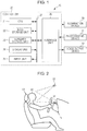
- Fig. 1 is a block diagram of the driver monitoring apparatus 10 according to this embodiment.
- This driver monitoring apparatus 10 has a controller 20, an illumination device 30, a photographic device 31, and a voice output device 32, as illustrated in Fig. 1 .
- the illumination device 30 emits light in the near infrared region, which is outside the visible light region, to the face of the driver.
- the illumination device 30 has, for example, a near infrared light-emitting diode (LED).
- This illumination device 30 is attached to, for example, a rear-view mirror, a steering column, or a dashboard, as illustrated in Fig. 2 .
- the illumination device 30 periodically switches the amount of light to be emitted between a first amount of light and a second amount of light at intervals of time T, under control of the controller 20, which will be described later. If, for example, the photographic device 31 captures images at a rate of 30 frames/second, the illumination device 30 changes the amount of light to be emitted 30 times per second. A plurality of frames of images may be captured in a period continuing until the amount of light is changed. To increase a rate at which the driver's state is detected, however, it is preferable to change the amount of light to be emitted at a rate matching the photographing rate set in the photographic device 31.
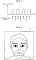
- Fig. 3 is a graph illustrating photographing timings and time-varying changes in the amount of light emitted from the illumination device 30, with time on the horizontal axis and the amount of light on the vertical axis.
- the second amount of light is, for example, zero. That is, Fig. 3 illustrates a case in which the controller 20 controls the illumination device 30 so that it is periodically turned on and off at intervals of time T. In the on period, a predetermined amount of light is emitted. In an off period, light is not emitted. Timings at which the amount of light is changed are synchronized with photographing timings set in the photographic device 31. In Fig.
- the symbols B1, B2, B3, and B4 are timings at which pictures are taken in a period during which the illumination device 30 emits light
- the symbols D1, D2, and D3 are timings at which pictures are taken during a period in which the illumination device 30 emits no light. That is, the photographic device 31 captures a one-frame image in a period during which the illumination device 30 is emitting light and captures another one-frame image in a next period during which the illumination device 30 is emitting no light.
- the photographic device 31 is, for example, a type of photographic device having a charge-coupled device (CCD) camera. This photographic device 31 is attached to, for example, a steering column or a dashboard as illustrated in Fig. 2 .
- the photographic device 31 takes a picture of the face of a driver 60.
- Fig. 4 illustrates an image P of the driver 60, which is captured by the photographic device 31.
- the attachment position and viewing angle of the photographic device 31 is adjusted so that the face of the driver 60 seated on a seat 61 illustrated in Fig. 2 is positioned at the center of a field of view.
- This photographic device 31 sequentially takes pictures of the face of the driver 60 at a rate of, for example, 30 frames/second, and sequentially outputs image information PD about images P obtained by photography to the controller 20.
- the voice output device 32 outputs a voice to the driver 60 in response to a command from the controller 20.
- This voice output device 32 has an amplifier and a speaker that are used to output a voice. If, for example, the controller 20 determines that the concentration of the driver 60 has dropped, the voice output device 32 outputs the voice "Dangerous", "Take care", or the like.
- the controller 20 is a computer or computer system that has a central processing unit (CPU) 21, a main storage unit 22, an auxiliary storage unit 23, a display unit 24, an input unit 25, and an interface unit 26, as illustrated in Fig. 1 .
- CPU central processing unit
- main storage unit 22 main storage unit 22
- auxiliary storage unit 23 main storage unit 23
- display unit 24 an input unit 25
- interface unit 26 as illustrated in Fig. 1 .
- the CPU 21 executes processing, which will be described later, according to a program stored in the auxiliary storage unit 23.
- the main storage unit 22 includes a random-access memory (RAM) and the like.
- the main storage unit 22 functions as a working area used by the CPU 21.
- the auxiliary storage unit 23 has a non-volatile memory such as a read-only memory (ROM), a magnetic disk, a semiconductor memory, or the like.
- the auxiliary storage unit 23 prestores programs executed by the CPU 21 and various types of parameters.
- the auxiliary storage unit 23 also stores the image information PD output from the photographic device 31 and processing results obtained from the CPU 21.
- the display unit 24 has, for example, a liquid crystal display (LCD).
- the display unit 24 displays processing results obtained from the CPU 21 and other information.
- the input unit 25 has input keys and pointing devices such as a touch panel.
- the CPU 21 is notified of the command through a system bus 27.
- the interface unit 26 has a serial interface and a parallel interface.
- the illumination device 30, photographic device 31, and voice output device 32 are connected to the system bus 27 through the interface unit 26.
- the controller 20 functionally has a light amount control unit 51, a brightness correcting unit 52, a differential image creating unit 53, an extended correction unit 54, a face detecting unit 55, and a state detecting unit 56, as illustrated in Fig. 5 .
- the light amount control unit 51 controls the amount of light to be emitted from the illumination device 30 so that the amount of light becomes the first amount of light or second amount of light. As illustrated in Fig. 3 , the light amount control unit 51 controls the illumination device 30 so that the amount of light to be emitted from the illumination device 30 is changed in synchronization with the photographing timing taken by the photographic device 31. In this synchronization method, a timing at which to change the amount of light from the illumination device 30 may be synchronized with the photographing timing taken by the photographic device 31. Alternatively, the photographing timing taken by the photographic device 31 may be synchronized with a timing at which to change the amount of light from the illumination device 30.
- the brightness correcting unit 52 subtracts the amount of correction for brightness that has been automatically corrected by the photographic device 31 from brightness in image information obtained from the photographic device 31. It will be assumed that brightness in the image information PD output from the photographic device 31 is represented in the range from 0 to 255. If, for example, the value of the highest brightness among the pixels of a captured image is low (30 or less, for example), differences in brightness among the pixels are small, resulting in an unclear image. In view of this, many photographic devices automatically correct brightness so that the value of the highest brightness (30, for example) becomes, for example 255.
- the image information PD that has been automatically corrected in this way is used to create differential image information S1 from a difference in brightness between the image information PD about an image captured at timing B1 indicated in Fig. 3 and the image information PD about an image captured at timing D1 indicated in Fig. 3 , the resulting image is not an image based on only light emitted from the illumination device 30. That is, an image from which ambient light has been eliminated is not obtained.
- the brightness correcting unit 52 subtracts the amount of correction for brightness that has been automatically corrected by the photographic device 31 from brightness in image information obtained from the photographic device 31.
- the brightness correcting unit 52 acquires, from the photographic device 31, the amount of correction for brightness that has been automatically corrected by the photographic device 31.
- the brightness correcting unit 52 can also infer the amount of correction for corrected brightness from, for example, an exposure time taken by the photographic device 31.
- the differential image creating unit 53 compares image information about one image on which the face of the driver 60 to which the first amount of light was emitted is photographed with image information about another image on which the face of the driver 60 to which the second amount of light was emitted is photographed. The differential image creating unit 53 then creates a differential image from differential information about brightness of corresponding pixels. Specifically, to create differential image information S1, the differential image creating unit 53 subtracts brightness of each pixel indicated in the image information PD about an image captured at timing D1 indicated in Fig. 3 from brightness of the corresponding pixel indicated in the image information PD about an image captured at timing B1 indicated in Fig. 3 to obtain a difference in brightness for each two corresponding pixels.
- the differential image creating unit 53 creates differential image information S1 by making a comparison between the image information PD about an image captured at timing B2 indicated in Fig. 3 and the image information PD about an image captured at timing D2 indicated in Fig. 3 to obtain a difference in brightness for each two corresponding pixels. This is also true for subsequent timings.
- the extended correction unit 54 corrects the brightness of the differential image created by the differential image creating unit 53. Specifically, the extended correction unit 54 applies histogram expansion to the differential image information S1 created by the differential image creating unit 53 to correct the brightness. Histogram expansion is processing in which, among the pixels of an image, the lowest brightness is set to, for example, 0 and the highest brightness is set to, for example, 255. Brightness at intermediate levels undergoes conversion correction by proportional apportionment. In a brightness distribution for the differential image information S1, pixels may concentrate in a low-brightness region. That is, in frequency analysis performed for the brightness of the pixels included in the differential image information S1, a difference between the lowest brightness and the highest brightness may be small, as illustrated in Fig. 6A .
- the extended correction unit 54 performs extended correction so that the highest brightness indicated in Fig. 6A takes a value of, for example, 255.
- Fig. 6B illustrates a brightness distribution obtained by applying extended correction to Fig. 6A . Due to this correction, differences in brightness among the pixels can be increased, so it is possible to create a sharp image on which the face portion, background, eyes, nose, mouth, and the like can be easily distinguished.
- the face detecting unit 55 detects, from post-extended-correction differential image information S2, the eyes, nose, and mouth of the driver 60 as well as the orientation of the face and the open/closed state of the eyes, which will be described later in detail.
- the state detecting unit 56 detects the state of the driver 60 from images for the eyes, nose, and mouth of the driver 60 as well as the orientation of the face and the open/closed state of the eyes, which have been detected. Specifically, the state detecting unit 56 infers a drop in the concentration of the driver 60 from the orientation of the face and the open/closed state of the eyes.
- the controller 20 structured as described above monitors the driver 60. If, for example, the controller 20 determines that the concentration of the driver 60 has dropped, the controller 20 outputs an alarm to the driver 60.
- the operation of the driver monitoring apparatus 10 according to this embodiment will be described below with reference to the drawings.
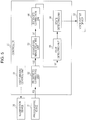
- the flowchart in Fig. 7 is based on a series of monitoring processing algorithms of programs executed by the CPU 21.
- a series of monitoring processing illustrated in the flowchart in Fig. 7 is executed when, for example, the ignition switch of the vehicle is turned on.
- the CPU 21 receives image information PD sequentially transmitted from the photographic device 31 and performs image processing to create differential image information S2 (step S10). Specifically, as illustrated in Fig. 8 , the brightness correcting unit 52 creates image information PD2, which is information before automatic brightness correction by the photographic device 31, through brightness correction (step S11). Next, the differential image creating unit 53 creates differential image information S1 from image information PD2 about an image captured in a period during which the illumination device 30 emits light and image information PD2 about an image captured in a period during which the illumination device 30 emits no light (step S12). In addition, the extended correction unit 54 performs histogram extended correction on the differential image information S1 to create differential image information S2 (step S13). Upon completion of the processing in step S13, the CPU 21 causes processing to proceed to step S20 in Fig. 7 .
- the CPU 21 performs state detection processing, which will be described later with reference to Fig. 9 , to detect the state of the driver 60 from the image P stipulated by the differential image information S2 (step S20).
- the flowchart in Fig. 9 illustrates a series of processing executed by the CPU 21 in state detection processing.
- the CPU 21 first executes head detection processing to detect the head of the driver 60 from the image P represented by the differential image information S2 (step S101).
- head detection processing the head of the driver 60 is detected according to, for example, feature values such as the brightness of pixels constituting the head, edges representing a boundary between the head of the driver 60 on the image P and its background, and edges representing a boundary between the head and the face.
- the CPU 21 calculates a likelihood that is a probability that the edge is part of the head. If the sum of the likelihoods for all edges exceeds a threshold, the CPU 21 decides that the head is present on the image P.
- a template may be used to detect the head.
- the CPU 21 Upon completion of the head detection processing, the CPU 21 performs face outline detection processing to detect the outline of the face of the driver 60 from the image P (step S102).
- face outline detection processing the outline of the face of the driver 60 is detected according to, for example, feature values such as the brightness of pixels constituting the face and edges representing a boundary between the face of the driver 60 on the image P and its background.
- the CPU 21 calculates a likelihood that is a probability that the edge is part of the outline of the face. If the sum of the likelihoods for all edges exceeds a threshold, the CPU 21 decides that the outline of the face is present on the image P.
- a template may be used to detect the face.
- the CPU 21 Upon completion of the face outline detection processing, the CPU 21 performs eye detection processing to detect the eyes of the driver 60 from the image P (step S103).
- eye detection processing the eyes of the driver 60 are detected according to, for example, feature values such as the brightness of pixels constituting the eyes and edges representing boundaries between the eyes and other portions of the face of the driver 60 on the image P.
- the CPU 21 calculates a likelihood that is a probability that the edge is part of the outline of the eyelids and irises constituting the eyes. If the sum of the likelihoods for all edges exceeds a threshold, the CPU 21 decides that an image of the eyes is present on the image P.
- the CPU 21 may use a template for eyes to detect the eyes of the driver 60 from the image P. In this case, while moving the template for eye detection on the upper surface of the image P, the CPU 21 calculates a correlation value indicating a normalized mutual correlation as the likelihood. The CPU 21 decides that the image of the eyes is present at the position of the template when the likelihood is equal to or larger than a threshold and is the largest.
- the CPU 21 performs nose detection processing to detect the nose of the driver 60 from the image P (step S104).
- nose detection processing the nose of the driver 60 is detected according to, for example, feature values such as the brightness of pixels constituting the nose and edges representing boundaries between the nose and other portions of the driver 60 on the image P.
- a template may be used to detect the nose, as in eye detection.
- the CPU 21 Upon completion of the nose detection processing, the CPU 21 performs mouth detection processing to detect the mouth of the driver 60 from the image P (step S105).
- mouth detection processing the mouth of the driver 60 is detected according to, for example, feature values such as the brightness of pixels constituting the mouth and edges representing boundaries between the mouth and other portions of the face of the driver 60 on the image P.
- a template may be used to detect the mouth, as in eye detection.
- head detection processing, face outline detection processing, eye detection processing, nose detection processing, and mouth detection processing are performed by using a detection parameter or template based on the value of a counter value n1. If, for example, the counter value n1 is 0, a detection parameter or template optimized to an image of the face facing the front is used to detect the head, the outline of the face, the eyes, the nose, or the mouth. If the counter value n1 is 1, a detection parameter or template optimized to an image of the face facing to the left at an oblique angle is used to detect the head, the outline of the face, the eyes, the nose, or the mouth.
- n1 a detection parameter or template optimized to an image of the face facing to the right at an oblique angle is used to detect the head, the outline of the face, the eyes, the nose, or the mouth.
- n1 a detection parameter or template optimized to an image of the face facing to the left is used to detect the head, the outline of the face, the eyes, the nose, or the mouth.
- n1 a detection parameter or template optimized to an image of the face facing to the right is used to detect the head, the outline of the face, the eyes, the nose, or the mouth.
- a likelihood is obtained from the feature values of a detection parameter or template indicated in Table 1 and the feature values extracted from the image P, after which it is determined whether the head, the outline of the face, the eyes, the nose, or the mouth has been detected, depending on whether the obtained likelihood is equal to or larger than a threshold.
- Table 1 Counter value n1 Detection parameter or template to be used 0 Optimized to an image of the face facing the front. 1 Optimized to an image of the face facing to the left at an oblique angle. 2 Optimized to an image of the face facing to the right at an oblique angle. 3 Optimized to an image of the face facing to the left. 4 Optimized to an image of the face facing to the right.
- the CPU 21 decides whether the face stipulated by the counter value n1 has been detected from the image P (step S106). If, for example, the counter value n1 is 0, a detection parameter or template optimized to an image of the face facing the front is used to detect the head, the outline of the face, the eyes, the nose, and the mouth in processing in steps S101 to S105 above. If any one of the head, the outline of the face, the eyes, the nose, and the mouth that correspond to the detection parameter optimized to an image of the face facing the front is not detected from the image P, it is decided that the face facing the front has not been detected from the image P.
- the head, the outline of the face, the eyes, the nose, and the mouth that correspond to that detection parameter are detected from the image P, it is decided that the face facing the front has been detected from the image P.
- the counter value n1 is 1, a detection parameter or template optimized to an image of the face facing to the left at an oblique angle is used to detect the head, the outline of the face, the eyes, the nose, and the mouth. This is also true for other values of the counter value n1.
- step S106 If the CPU 21 decides that the face stipulated by the detection parameter indicated by the counter value n1 has been detected (the result in step S106 is Yes), the CPU 21 increments the value of a counter value m, which indicates the number of detections, by one (step S107). This is done to leave a history of the detection of the corresponding face.
- step S106 If the CPU 21 decides that the corresponding face has not been detected from the image P (the result in step S106 is No) or has terminated the processing in step S107, the CPU 21 increments the value of the counter value n1 by one (step S108). Next, the CPU 21 decides whether the value of the counter value n1 is larger than 4 (step S109). If processing in which the five detection parameters or templates indicated in Table 1 are used has not been terminated for the image P (the result in step S109 is No), the CPU 21 uses a next detection parameter or template to repeatedly execute processing in steps S101 to S109.
- step S109 If five types of comparison processing in which the five detection parameters or templates indicated in Table 1 are used has been terminated (the result in step S109 is Yes), the CPU 21 resets the counter value n1 and decides whether the counter value m, which indicates the number of detections, is larger than 0 (step S110). If the CPU 21 decides that a face has never been detected from the image P (if m is 0) (the result in step S110 is No), the CPU 21 resets the counter value m, terminates the state detection processing, and causes processing to return to step S10. The CPU 21 then executes processing in steps S10 and S20 for next image information PD.
- step S110 If the CPU 21 decides that a face has been detected from the image P at least once (if m is larger than 0) (the result in step S110 is Yes), the CPU 21 resets the counter value m and selects the largest likelihood of the counter value n1 (step S111). In the selection of the largest likelihood, the CPU 21 calculates the sum of likelihoods in processing in steps S101 to S105 for each value of the counter value n1.
- likelihoods for the head, the outline of the face, the eyes, the nose, and the mouth in processing in steps S101 to S105 are respectively denoted LH1, LH1, LH3, LH4, and LH5
- the CPU 21 makes a decision as to the orientation of the face of the driver 60 according to the selection result based on the likelihood (step S112). Specifically, as seen from Table 1, if the likelihood is the largest when the counter value n1 is 0, the CPU 21 decides that the driver 60 faces the front. If the likelihood is the largest when the counter value n1 is 1, the CPU 21 decides that the driver 60 faces to the left at an oblique angle. If the likelihood is the largest when the counter value n1 is 2, the CPU 21 decides that the driver 60 faces to the right at an oblique angle. If the likelihood is the largest when the counter value n1 is 3, the CPU 21 decides that the driver 60 faces to the left. If the likelihood is the largest when the counter value n1 is 4, the CPU 21 decides that the driver faces to the right.
- the CPU 21 decides that the driver 60 faces in a direction other than the direction toward the front, the CPU 21 drives the voice output device 32 to issue an alarm such as "View the front" to the driver 60.
- the CPU 21 uses the image P to decide whether the eyelids of the driver 60 are open or closed (step S113).
- a distance between an edge representing the upper eyelid of the eye and an edge representing the lower eyelid of the eye is compared with a threshold. If the CPU 21 decides that the eyelids of the driver 60 are closed or that the number of times the eyelids are opened and closed is small, the CPU 21 drives the voice output device 32 to issue an alarm such as "Dangerous" or "Wake up" to the driver 60. If only one eye has been detected, the CPU 21 does not make a decision as to whether the eyelids are open or closed.
- step S113 Upon completion of the processing in step S113, the CPU 21 causes processing to return to step S10. The CPU 21 then executes processing in steps S10 and S20 for next image information PD.
- the method of making a decision as to the state (drop in concentration) of the driver 60 does not need to be limited to this technology.
- a drop in the concentration of the driver 60 can be decided with respect to the situation in the direction in which the vehicle travels.
- the direction of the line of vision can be obtained according to a known technology.
- a controller 20b in the driver monitoring apparatus 10 according to a second embodiment differs from the controller 20 in the driver monitoring apparatus 10 according to the first embodiment in that, as illustrated in Fig. 10 , the controller 20b has an image switching unit 57 by which a switchover is made to select image information to be supplied to the face detecting unit 55 depending on the amount of ambient light directed to the face of the driver 60.
- the average brightness in the image information PD about a captured image is high. If a comparison is made in this situation between brightness in the image information PD obtained by photography in a state in which light is emitted from the illumination device 30 and brightness in the image information PD obtained by photography in a state in which no light is emitted, a difference in brightness is small.
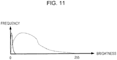
- the differential image information S1 pixels concentrate in a region in which brightness is extremely low, as indicated by the solid line in Fig. 11 . If histogram expansion is performed on this distribution as indicated by the dotted line in Fig. 11 , the noise component included in the differential image information S1 is emphasized too much, which may lower precision in image analysis. Even if face detection and state detection are performed according to the image information PD obtained from the photographic device 31 in the case in which much ambient light is directed to the face of the driver 60, precision in image analysis is less likely to be lowered.
- the image switching unit 57 makes a switchover to select image information to be supplied to the face detecting unit 55 depending on the amount of ambient light directed to the face of the driver 60. Specifically, if the amount of ambient light directed to the face of the driver 60 is smaller than a threshold, the image switching unit 57 supplies, to the face detecting unit 55, the differential image information S2 created by the brightness correcting unit 52, differential image creating unit 53, and extended correction unit 54, as described in the first embodiment. If the amount of ambient light directed to the face of the driver 60 is equal to or larger than the threshold, the image switching unit 57 supplies the image information PD obtained from the photographic device 31 to the face detecting unit 55 without alteration.
- the image information PD obtained from the photographic device 31 may be image information in a period during which the illumination device 30 emits light or may be image information in a period during which the illumination device 30 emits no light. This is because a difference in brightness between them is small.
- the image switching unit 57 infers the amount of ambient light directed to the face of the driver 60 from an exposure time obtained from the photographic device 31. This inference is based on the fact that the larger the amount of ambient light directed to the face of the driver 60 is, the shorter the exposure time taken by the photographic device 31 is. Alternatively, the image switching unit 57 may infer the amount of ambient light directed to the face of the driver 60 from illuminance in the portion of the face of the driver 60, the illuminance being obtained from an illumination sensor (not illustrated).
- the driver monitoring apparatus 10 which has the light amount control unit 51, captures an image under different amounts of light emitted from the illumination device 30.
- the differential image creating unit 53 creates differential image information S1 according to a difference in brightness between images captured under the different amounts of light.
- the influence of ambient light is eliminated from image information.
- the face detecting unit 55 detects the eyes and other portions of the driver 60 and the state detecting unit 56 detects the state of the driver 60.
- the driver monitoring apparatus 10 according to this embodiment can reduce a drop caused due to ambient light in precision with which the state of the driver 60 is detected.
- the driver monitoring apparatus 1C which has the extended correction unit 54, creates the differential image information S2 in which changes in brightness in the differential image information S1 are enlarged. This can further improve precision with which the state of the driver 60 is detected.
- the driver monitoring apparatus 10 which has the light amount control unit 51, controls the illumination device 30 so that the amount of light to be emitted in synchronization with a photographing timing taken by the photographic device 31 is changed.
- differential image information S1 can be created according to the photographic capacity of the photographic device 31, so it is possible to prevent a drop in precision in the detection of the state of the driver 60, the drop being otherwise caused by the motion of the driver 60 as time elapses. It is also possible to increase the response speed of the driver monitoring apparatus 10.
- the driver monitoring apparatus 10 has the brightness correcting unit 52. Therefore, even if the photographic device 31 automatically corrects brightness, the influence of ambient light can be eliminated and the state of the driver 60 can thereby be detected accurately.
- the driver monitoring apparatus 10 in the second embodiment has the image switching unit 57. Therefore, even if much ambient light is directed to the face of the driver 60, it is possible to reduce a drop in precision with which the state of the driver 60 is detected.
- brightness to be corrected by the brightness correcting unit 52 has been obtained from the photographic device 31.
- the method of correcting brightness may be changed according to the correction characteristics of the photographic device 31.
- illuminance in the portion of the face of the driver 60 may be obtained from an illumination sensor, after which the amount of ambient light directed to the face of the driver 60 may be inferred according to the illuminance.
- the brightness correction characteristics of the photographic device 31 may be prestored in a storage unit in correspondence to the amount of light directed to the subject, as a table. Then, the amount of correction may be obtained with reference to the table.
- the illumination device 30 has emitted near-infrared light.
- light to be emitted does not need to be limited to near-infrared light. If the object is to remove the influence of ambient light, visible light or ultraviolet light, for example, may be used. However, since the eyes of the driver 60 are illuminated by light, light in a frequency band in which the eyes are not damaged and driving is not impeded needs to be selected.
- the illumination device 30 has been controlled so as to be turned on and off.
- the illumination device 30 may be controlled so that the amount of light to be emitted from the illumination device 30 is increased or decreased. If, for example, a response from the illumination device 30 is slow when the illumination device 30 stops emitting light and restarts emission, control in increasing or decreasing the amount of light is more preferable than on/off control.
- the photographic device 31 has captured one frame of image each time the illumination device 30 changes the amount of light to be emitted.
- this is not a limitation on a relationship between a photographing timing and a timing at which to change the amount of light.
- a plurality of images may be captured each time the amount of light to be emitted is changed. This is effective when the photographing speed of the photographic device 31 is equal to or higher than the photographing speed demanded according to precision in image analysis.
- brightness in the differential image information S2 about the plurality of images is statistically processed. Although various statistical processing methods are available, brightness information that is extremely unsuitable may be eliminated or the average of brightness may be calculated, for example. Thus, the signal-to-noise (S/N) ratio can be improved and precision in analysis can be thereby improved.
- S/N signal-to-noise
- step S20 If state detection processing in step S20 takes a longer processing time than image processing in step S10, the differential image information S2 may be selectively used. In this case, a plurality of pieces of differential image information S2 that have been statistically processed may be supplied to the face detecting unit 55. This is because when statistical processing is performed, improvement in precision in image analysis can be expected.
- the differential image information S1 is not limited to differential image information between the image information PD about an image captured at timing B1 indicated in Fig. 3 and the image information PD about an image captured at timing D1 indicated in Fig. 3 .
- other differential image information may be created between the image information PD about an image captured at timing D1 and the image information PD about an image captured at timing B2. Therefore, as much as twice more differential image information can be created. Due to this processing, even in the third case described in the first embodiment, differential image information in which the influence by ambient light has been eliminated can be obtained as differential image information between the image information PD about an image captured at timing D1 and the image information PD about an image captured at timing B2.
- the maximum value of brightness in the obtained differential image information S1 has been 255.
- the upper limit of brightness may be suppressed to about 200.
- brightness needs to be corrected so as to prevent halation in the pupil portion. This is because the brightness in the image of the pupils may become high due to low surrounding luminance, and, in this case, if the brightness in the image of the pupils is excessively increased, halation occurs in the pupil portion, which may prevent correct image analysis.
- the state detecting unit 56 has detected the state of the driver 60 from the eyes, nose, and mouth of the driver 60 as well as the orientation of the face and the open/closed state of the eyes, which have been detected by the face detecting unit 55.
- this is not a limitation on the method of detecting the state of the driver 60.
- detection of the ears may be added.
- detection of the nose and mouth may be omitted.
- the state of the driver 60 has been determined for each frame and an alarm, for example, has been issued, if necessary. However, if it is decided for a plurality of successive images that an alarm needs to be issued, an alarm may be issued as necessary.
- the voice output device 32 has been operated according to the detection result obtained from the state detecting unit 56.
- the detection result may be output to an external device.
- the seat 61 may be vibrated to draw the attention of the driver 60.
Landscapes
- Engineering & Computer Science (AREA)
- Theoretical Computer Science (AREA)
- Physics & Mathematics (AREA)
- General Physics & Mathematics (AREA)
- Multimedia (AREA)
- General Engineering & Computer Science (AREA)
- Human Computer Interaction (AREA)
- Signal Processing (AREA)
- Ophthalmology & Optometry (AREA)
- General Health & Medical Sciences (AREA)
- Health & Medical Sciences (AREA)
- Mechanical Engineering (AREA)
- Transportation (AREA)
- Mathematical Physics (AREA)
- Automation & Control Theory (AREA)
- Business, Economics & Management (AREA)
- Emergency Management (AREA)
- Computer Vision & Pattern Recognition (AREA)
- Image Processing (AREA)
- Traffic Control Systems (AREA)
- Auxiliary Drives, Propulsion Controls, And Safety Devices (AREA)
- Emergency Alarm Devices (AREA)
- Image Analysis (AREA)
Abstract
Description
- The present invention relates to a driver monitoring apparatus, a driver monitoring method, and a computer program product.
- One of various possible traffic accidents is a human error caused by a drop in the driver's concentration. Human errors frequently occur when, for example, the driver takes an action other than driving operation, such as a conversation or a manipulation of a vehicle-mounted device, or the driver's concentration on driving operation drops due to, for example a fatigue or sleep.
- The driver cannot easily prevent the concentration drop caused by a fatigue or sleep by itself. In view of this, various technologies are proposed that detect driver's states typified by a drowse. For example, a technology is known that analyzes images, obtained by photography, of the driver's face and infers the driver's state. In a conventional recognition technology that uses an in-vehicle camera, however, precision in the detection of the driver's state has sometimes been lowered by ambient light, such as street lamp light, which causes variations in illuminance.
- A related technique is disclosed in, for example, Japanese Patent No.
4728432 - The present invention addresses the above situation with the object of reducing a drop, caused by ambient light, in precision with which the driver's state is detected.
- The invention relates to a driver monitoring apparatus, a driver monitoring method, and a computer program product according to the appended claims. Embodiments are disclosed in the dependent claims.
- According to an aspect of the invention, a driver monitoring apparatus according to an embodiment has a photographing means for taking a picture of the face of a driver, an illumination means for emitting light to the face of the driver, a light amount control means for controlling the amount of light to be emitted from the illumination means so that the amount of light becomes a first amount of light or a second amount of light, a differential image creating means for comparing image information about one image on which the face of the driver to which the first amount of light was emitted is photographed with image information about another image on which the face of the driver to which the second amount of light was emitted is photographed and then creating a differential image from differential information about brightness of corresponding pixels, a detecting means for detecting the eyes of the driver from the differential image created by the differential image creating means, and a state detecting means for detecting the state of the driver according to an image of the eyes of the driver.
-
Fig. 1 is a block diagram of a driver monitoring apparatus according to a first embodiment; -
Fig. 2 illustrates the position of a photographic device according to the first embodiment; -
Fig. 3 is a graph illustrating photographing timings; -
Fig. 4 illustrates an image captured by the photographic device; -
Fig. 5 is a block diagram of a controller according to the first embodiment; -
Figs. 6A and 6B are graphs illustrating extended correction; -
Fig. 7 is a flowchart illustrating a series of processing executed by a CPU; -
Fig. 8 is a flowchart illustrating a series of image processing executed by the CPU; -
Fig. 9 is a flowchart illustrating a series of state detection processing executed by the CPU; -
Fig. 10 is a block diagram of a controller according to a second embodiment; and -
Fig. 11 is a graph to explain an image switching unit according to a second embodiment. - A driver monitoring apparatus in this embodiment monitors the state of the driver who operates a vehicle according to the orientation of the driver's face, the open/closed state of the eyes, and the like. This embodiment will be described below with reference to the drawings.
-
Fig. 1 is a block diagram of thedriver monitoring apparatus 10 according to this embodiment. Thisdriver monitoring apparatus 10 has acontroller 20, anillumination device 30, aphotographic device 31, and avoice output device 32, as illustrated inFig. 1 . - The
illumination device 30 emits light in the near infrared region, which is outside the visible light region, to the face of the driver. Theillumination device 30 has, for example, a near infrared light-emitting diode (LED). Thisillumination device 30 is attached to, for example, a rear-view mirror, a steering column, or a dashboard, as illustrated inFig. 2 . - The
illumination device 30 periodically switches the amount of light to be emitted between a first amount of light and a second amount of light at intervals of time T, under control of thecontroller 20, which will be described later. If, for example, thephotographic device 31 captures images at a rate of 30 frames/second, theillumination device 30 changes the amount of light to be emitted 30 times per second. A plurality of frames of images may be captured in a period continuing until the amount of light is changed. To increase a rate at which the driver's state is detected, however, it is preferable to change the amount of light to be emitted at a rate matching the photographing rate set in thephotographic device 31. -
Fig. 3 is a graph illustrating photographing timings and time-varying changes in the amount of light emitted from theillumination device 30, with time on the horizontal axis and the amount of light on the vertical axis. InFig. 3 , the second amount of light is, for example, zero. That is,Fig. 3 illustrates a case in which thecontroller 20 controls theillumination device 30 so that it is periodically turned on and off at intervals of time T. In the on period, a predetermined amount of light is emitted. In an off period, light is not emitted. Timings at which the amount of light is changed are synchronized with photographing timings set in thephotographic device 31. InFig. 3 , the symbols B1, B2, B3, and B4 are timings at which pictures are taken in a period during which theillumination device 30 emits light, and the symbols D1, D2, and D3 are timings at which pictures are taken during a period in which theillumination device 30 emits no light. That is, thephotographic device 31 captures a one-frame image in a period during which theillumination device 30 is emitting light and captures another one-frame image in a next period during which theillumination device 30 is emitting no light. - The
photographic device 31 is, for example, a type of photographic device having a charge-coupled device (CCD) camera. Thisphotographic device 31 is attached to, for example, a steering column or a dashboard as illustrated inFig. 2 . Thephotographic device 31 takes a picture of the face of adriver 60.Fig. 4 illustrates an image P of thedriver 60, which is captured by thephotographic device 31. As seen fromFig. 4 , the attachment position and viewing angle of thephotographic device 31 is adjusted so that the face of thedriver 60 seated on aseat 61 illustrated inFig. 2 is positioned at the center of a field of view. Thisphotographic device 31 sequentially takes pictures of the face of thedriver 60 at a rate of, for example, 30 frames/second, and sequentially outputs image information PD about images P obtained by photography to thecontroller 20. - Referring again to
Fig. 1 , thevoice output device 32 outputs a voice to thedriver 60 in response to a command from thecontroller 20. Thisvoice output device 32 has an amplifier and a speaker that are used to output a voice. If, for example, thecontroller 20 determines that the concentration of thedriver 60 has dropped, thevoice output device 32 outputs the voice "Dangerous", "Take care", or the like. - Physically, the
controller 20 is a computer or computer system that has a central processing unit (CPU) 21, amain storage unit 22, anauxiliary storage unit 23, adisplay unit 24, aninput unit 25, and aninterface unit 26, as illustrated inFig. 1 . - The
CPU 21 executes processing, which will be described later, according to a program stored in theauxiliary storage unit 23. - The
main storage unit 22 includes a random-access memory (RAM) and the like. Themain storage unit 22 functions as a working area used by theCPU 21. - The
auxiliary storage unit 23 has a non-volatile memory such as a read-only memory (ROM), a magnetic disk, a semiconductor memory, or the like. Theauxiliary storage unit 23 prestores programs executed by theCPU 21 and various types of parameters. Theauxiliary storage unit 23 also stores the image information PD output from thephotographic device 31 and processing results obtained from theCPU 21. - The
display unit 24 has, for example, a liquid crystal display (LCD). Thedisplay unit 24 displays processing results obtained from theCPU 21 and other information. - The
input unit 25 has input keys and pointing devices such as a touch panel. When an operator's command is entered through theinput unit 25, theCPU 21 is notified of the command through asystem bus 27. - The
interface unit 26 has a serial interface and a parallel interface. Theillumination device 30,photographic device 31, andvoice output device 32 are connected to thesystem bus 27 through theinterface unit 26. - The
controller 20 functionally has a lightamount control unit 51, abrightness correcting unit 52, a differentialimage creating unit 53, anextended correction unit 54, aface detecting unit 55, and astate detecting unit 56, as illustrated inFig. 5 . - The light
amount control unit 51 controls the amount of light to be emitted from theillumination device 30 so that the amount of light becomes the first amount of light or second amount of light. As illustrated inFig. 3 , the lightamount control unit 51 controls theillumination device 30 so that the amount of light to be emitted from theillumination device 30 is changed in synchronization with the photographing timing taken by thephotographic device 31. In this synchronization method, a timing at which to change the amount of light from theillumination device 30 may be synchronized with the photographing timing taken by thephotographic device 31. Alternatively, the photographing timing taken by thephotographic device 31 may be synchronized with a timing at which to change the amount of light from theillumination device 30. - While the
photographic device 31 is automatically correcting brightness, to create pre-automatic-brightness-correction image information PD2, thebrightness correcting unit 52 subtracts the amount of correction for brightness that has been automatically corrected by thephotographic device 31 from brightness in image information obtained from thephotographic device 31. It will be assumed that brightness in the image information PD output from thephotographic device 31 is represented in the range from 0 to 255. If, for example, the value of the highest brightness among the pixels of a captured image is low (30 or less, for example), differences in brightness among the pixels are small, resulting in an unclear image. In view of this, many photographic devices automatically correct brightness so that the value of the highest brightness (30, for example) becomes, for example 255. Even if the image information PD that has been automatically corrected in this way is used to create differential image information S1 from a difference in brightness between the image information PD about an image captured at timing B1 indicated inFig. 3 and the image information PD about an image captured at timing D1 indicated inFig. 3 , the resulting image is not an image based on only light emitted from theillumination device 30. That is, an image from which ambient light has been eliminated is not obtained. - Therefore, as described above, to create pre-automatic-brightness-correction image information PD2, the
brightness correcting unit 52 subtracts the amount of correction for brightness that has been automatically corrected by thephotographic device 31 from brightness in image information obtained from thephotographic device 31. Thebrightness correcting unit 52 acquires, from thephotographic device 31, the amount of correction for brightness that has been automatically corrected by thephotographic device 31. Thebrightness correcting unit 52 can also infer the amount of correction for corrected brightness from, for example, an exposure time taken by thephotographic device 31. - The differential
image creating unit 53 compares image information about one image on which the face of thedriver 60 to which the first amount of light was emitted is photographed with image information about another image on which the face of thedriver 60 to which the second amount of light was emitted is photographed. The differentialimage creating unit 53 then creates a differential image from differential information about brightness of corresponding pixels. Specifically, to create differential image information S1, the differentialimage creating unit 53 subtracts brightness of each pixel indicated in the image information PD about an image captured at timing D1 indicated inFig. 3 from brightness of the corresponding pixel indicated in the image information PD about an image captured at timing B1 indicated inFig. 3 to obtain a difference in brightness for each two corresponding pixels. Then, the differentialimage creating unit 53 creates differential image information S1 by making a comparison between the image information PD about an image captured at timing B2 indicated inFig. 3 and the image information PD about an image captured at timing D2 indicated inFig. 3 to obtain a difference in brightness for each two corresponding pixels. This is also true for subsequent timings. - As a first case, it will be considered that identical ambient light is directed at timings B1 and D1. In this case, the influence of the ambient light can be completely eliminated due to processing by the differential
image creating unit 53. - As a second case, it will be considered that there is no ambient light at timing B1 and ambient light is directed only at timing D1. If pictures are taken at a rate of 30 frames/hour during driving at a speed of 36 km/hour, one image is captured each time a distance of about 30 cm is traveled. Ambient light may largely change even during a travel of about 30 cm. The brightness of pixels in a portion, of the image, to which ambient light has been directed is increased. Therefore, pixels in the portion to which ambient light has been directed take negative values in the differential image information S1. The differential
image creating unit 53 sets the brightness of each pixel that takes a negative value in the differential image information S1 to 0. If the ambient light is directed to a portion other than the face of thedriver 60, the brightness of the background behind the face of thedriver 60 takes a value of 0. Therefore, precision with which the portion of the face of thedriver 60 can be increased. - As a third case, it will be considered that ambient light is directed only at timing B1 and there is no ambient light at timing D1. In this case, the influence of the ambient light cannot be eliminated from the differential image information S1. When the probability of the occurrence of the first case to the third case is considered, however, the influence of ambient light can be eliminated with a high probability.
- The
extended correction unit 54 corrects the brightness of the differential image created by the differentialimage creating unit 53. Specifically, theextended correction unit 54 applies histogram expansion to the differential image information S1 created by the differentialimage creating unit 53 to correct the brightness. Histogram expansion is processing in which, among the pixels of an image, the lowest brightness is set to, for example, 0 and the highest brightness is set to, for example, 255. Brightness at intermediate levels undergoes conversion correction by proportional apportionment. In a brightness distribution for the differential image information S1, pixels may concentrate in a low-brightness region. That is, in frequency analysis performed for the brightness of the pixels included in the differential image information S1, a difference between the lowest brightness and the highest brightness may be small, as illustrated inFig. 6A . If an image has a small difference between the lowest brightness and the highest brightness, the image is not sharp and unclear. Theextended correction unit 54 performs extended correction so that the highest brightness indicated inFig. 6A takes a value of, for example, 255.Fig. 6B illustrates a brightness distribution obtained by applying extended correction toFig. 6A . Due to this correction, differences in brightness among the pixels can be increased, so it is possible to create a sharp image on which the face portion, background, eyes, nose, mouth, and the like can be easily distinguished. - The
face detecting unit 55 detects, from post-extended-correction differential image information S2, the eyes, nose, and mouth of thedriver 60 as well as the orientation of the face and the open/closed state of the eyes, which will be described later in detail. - The
state detecting unit 56 detects the state of thedriver 60 from images for the eyes, nose, and mouth of thedriver 60 as well as the orientation of the face and the open/closed state of the eyes, which have been detected. Specifically, thestate detecting unit 56 infers a drop in the concentration of thedriver 60 from the orientation of the face and the open/closed state of the eyes. - The
controller 20 structured as described above monitors thedriver 60. If, for example, thecontroller 20 determines that the concentration of thedriver 60 has dropped, thecontroller 20 outputs an alarm to thedriver 60. The operation of thedriver monitoring apparatus 10 according to this embodiment will be described below with reference to the drawings. - The flowchart in
Fig. 7 is based on a series of monitoring processing algorithms of programs executed by theCPU 21. A series of monitoring processing illustrated in the flowchart inFig. 7 is executed when, for example, the ignition switch of the vehicle is turned on. - The
CPU 21 receives image information PD sequentially transmitted from thephotographic device 31 and performs image processing to create differential image information S2 (step S10). Specifically, as illustrated inFig. 8 , thebrightness correcting unit 52 creates image information PD2, which is information before automatic brightness correction by thephotographic device 31, through brightness correction (step S11). Next, the differentialimage creating unit 53 creates differential image information S1 from image information PD2 about an image captured in a period during which theillumination device 30 emits light and image information PD2 about an image captured in a period during which theillumination device 30 emits no light (step S12). In addition, theextended correction unit 54 performs histogram extended correction on the differential image information S1 to create differential image information S2 (step S13). Upon completion of the processing in step S13, theCPU 21 causes processing to proceed to step S20 inFig. 7 . - Next, the
CPU 21 performs state detection processing, which will be described later with reference toFig. 9 , to detect the state of thedriver 60 from the image P stipulated by the differential image information S2 (step S20). - The flowchart in
Fig. 9 illustrates a series of processing executed by theCPU 21 in state detection processing. In state detection processing, theCPU 21 first executes head detection processing to detect the head of thedriver 60 from the image P represented by the differential image information S2 (step S101). In head detection processing, the head of thedriver 60 is detected according to, for example, feature values such as the brightness of pixels constituting the head, edges representing a boundary between the head of thedriver 60 on the image P and its background, and edges representing a boundary between the head and the face. For example, for each edge detected from the image P, theCPU 21 calculates a likelihood that is a probability that the edge is part of the head. If the sum of the likelihoods for all edges exceeds a threshold, theCPU 21 decides that the head is present on the image P. A template may be used to detect the head. - Upon completion of the head detection processing, the
CPU 21 performs face outline detection processing to detect the outline of the face of thedriver 60 from the image P (step S102). In face outline detection processing, the outline of the face of thedriver 60 is detected according to, for example, feature values such as the brightness of pixels constituting the face and edges representing a boundary between the face of thedriver 60 on the image P and its background. For example, for each edge detected from the image P, theCPU 21 calculates a likelihood that is a probability that the edge is part of the outline of the face. If the sum of the likelihoods for all edges exceeds a threshold, theCPU 21 decides that the outline of the face is present on the image P. A template may be used to detect the face. - Upon completion of the face outline detection processing, the
CPU 21 performs eye detection processing to detect the eyes of thedriver 60 from the image P (step S103). In eye detection processing, the eyes of thedriver 60 are detected according to, for example, feature values such as the brightness of pixels constituting the eyes and edges representing boundaries between the eyes and other portions of the face of thedriver 60 on the image P. For example, for each edge detected from the image P, theCPU 21 calculates a likelihood that is a probability that the edge is part of the outline of the eyelids and irises constituting the eyes. If the sum of the likelihoods for all edges exceeds a threshold, theCPU 21 decides that an image of the eyes is present on the image P. - The
CPU 21 may use a template for eyes to detect the eyes of thedriver 60 from the image P. In this case, while moving the template for eye detection on the upper surface of the image P, theCPU 21 calculates a correlation value indicating a normalized mutual correlation as the likelihood. TheCPU 21 decides that the image of the eyes is present at the position of the template when the likelihood is equal to or larger than a threshold and is the largest. - Next, the
CPU 21 performs nose detection processing to detect the nose of thedriver 60 from the image P (step S104). In nose detection processing, the nose of thedriver 60 is detected according to, for example, feature values such as the brightness of pixels constituting the nose and edges representing boundaries between the nose and other portions of thedriver 60 on the image P. A template may be used to detect the nose, as in eye detection. - Upon completion of the nose detection processing, the
CPU 21 performs mouth detection processing to detect the mouth of thedriver 60 from the image P (step S105). In mouth detection processing, the mouth of thedriver 60 is detected according to, for example, feature values such as the brightness of pixels constituting the mouth and edges representing boundaries between the mouth and other portions of the face of thedriver 60 on the image P. A template may be used to detect the mouth, as in eye detection. - As seen from Table 1, head detection processing, face outline detection processing, eye detection processing, nose detection processing, and mouth detection processing are performed by using a detection parameter or template based on the value of a counter value n1. If, for example, the counter value n1 is 0, a detection parameter or template optimized to an image of the face facing the front is used to detect the head, the outline of the face, the eyes, the nose, or the mouth. If the counter value n1 is 1, a detection parameter or template optimized to an image of the face facing to the left at an oblique angle is used to detect the head, the outline of the face, the eyes, the nose, or the mouth. If the counter value n1 is 2, a detection parameter or template optimized to an image of the face facing to the right at an oblique angle is used to detect the head, the outline of the face, the eyes, the nose, or the mouth. If the counter value n1 is 3, a detection parameter or template optimized to an image of the face facing to the left is used to detect the head, the outline of the face, the eyes, the nose, or the mouth. If the counter value n1 is 4, a detection parameter or template optimized to an image of the face facing to the right is used to detect the head, the outline of the face, the eyes, the nose, or the mouth.
- In the above detection processing, a likelihood is obtained from the feature values of a detection parameter or template indicated in Table 1 and the feature values extracted from the image P, after which it is determined whether the head, the outline of the face, the eyes, the nose, or the mouth has been detected, depending on whether the obtained likelihood is equal to or larger than a threshold.
Table 1 Counter value n1 Detection parameter or template to be used 0 Optimized to an image of the face facing the front. 1 Optimized to an image of the face facing to the left at an oblique angle. 2 Optimized to an image of the face facing to the right at an oblique angle. 3 Optimized to an image of the face facing to the left. 4 Optimized to an image of the face facing to the right. - Next, the
CPU 21 decides whether the face stipulated by the counter value n1 has been detected from the image P (step S106). If, for example, the counter value n1 is 0, a detection parameter or template optimized to an image of the face facing the front is used to detect the head, the outline of the face, the eyes, the nose, and the mouth in processing in steps S101 to S105 above. If any one of the head, the outline of the face, the eyes, the nose, and the mouth that correspond to the detection parameter optimized to an image of the face facing the front is not detected from the image P, it is decided that the face facing the front has not been detected from the image P. If the head, the outline of the face, the eyes, the nose, and the mouth that correspond to that detection parameter are detected from the image P, it is decided that the face facing the front has been detected from the image P. If the counter value n1 is 1, a detection parameter or template optimized to an image of the face facing to the left at an oblique angle is used to detect the head, the outline of the face, the eyes, the nose, and the mouth. This is also true for other values of the counter value n1. - If the
CPU 21 decides that the face stipulated by the detection parameter indicated by the counter value n1 has been detected (the result in step S106 is Yes), theCPU 21 increments the value of a counter value m, which indicates the number of detections, by one (step S107). This is done to leave a history of the detection of the corresponding face. - If the
CPU 21 decides that the corresponding face has not been detected from the image P (the result in step S106 is No) or has terminated the processing in step S107, theCPU 21 increments the value of the counter value n1 by one (step S108). Next, theCPU 21 decides whether the value of the counter value n1 is larger than 4 (step S109). If processing in which the five detection parameters or templates indicated in Table 1 are used has not been terminated for the image P (the result in step S109 is No), theCPU 21 uses a next detection parameter or template to repeatedly execute processing in steps S101 to S109. - If five types of comparison processing in which the five detection parameters or templates indicated in Table 1 are used has been terminated (the result in step S109 is Yes), the
CPU 21 resets the counter value n1 and decides whether the counter value m, which indicates the number of detections, is larger than 0 (step S110). If theCPU 21 decides that a face has never been detected from the image P (if m is 0) (the result in step S110 is No), theCPU 21 resets the counter value m, terminates the state detection processing, and causes processing to return to step S10. TheCPU 21 then executes processing in steps S10 and S20 for next image information PD. - If the
CPU 21 decides that a face has been detected from the image P at least once (if m is larger than 0) (the result in step S110 is Yes), theCPU 21 resets the counter value m and selects the largest likelihood of the counter value n1 (step S111). In the selection of the largest likelihood, theCPU 21 calculates the sum of likelihoods in processing in steps S101 to S105 for each value of the counter value n1. - If likelihoods for the head, the outline of the face, the eyes, the nose, and the mouth in processing in steps S101 to S105 are respectively denoted LH1, LH1, LH3, LH4, and LH5, a likelihood LHn1 corresponding to an arbitrary counter value n1 is represented as the sum of LH1 to LH5 (LHn1 = LH1 + LH2 + LH3 + LH4 + LH5). Therefore, the
CPU 21 calculates the likelihood LHn1 for each of the values (0 to 4) of the counter value n1. Then, theCPU 21 selects the value of the counter value n1 corresponding to the largest likelihood LHn1. - Next, the
CPU 21 makes a decision as to the orientation of the face of thedriver 60 according to the selection result based on the likelihood (step S112). Specifically, as seen from Table 1, if the likelihood is the largest when the counter value n1 is 0, theCPU 21 decides that thedriver 60 faces the front. If the likelihood is the largest when the counter value n1 is 1, theCPU 21 decides that thedriver 60 faces to the left at an oblique angle. If the likelihood is the largest when the counter value n1 is 2, theCPU 21 decides that thedriver 60 faces to the right at an oblique angle. If the likelihood is the largest when the counter value n1 is 3, theCPU 21 decides that thedriver 60 faces to the left. If the likelihood is the largest when the counter value n1 is 4, theCPU 21 decides that the driver faces to the right. - If the
CPU 21 decides that thedriver 60 faces in a direction other than the direction toward the front, theCPU 21 drives thevoice output device 32 to issue an alarm such as "View the front" to thedriver 60. - Next, the
CPU 21 uses the image P to decide whether the eyelids of thedriver 60 are open or closed (step S113). In the decision as to whether the eyelids are open or closed, a distance between an edge representing the upper eyelid of the eye and an edge representing the lower eyelid of the eye is compared with a threshold. If theCPU 21 decides that the eyelids of thedriver 60 are closed or that the number of times the eyelids are opened and closed is small, theCPU 21 drives thevoice output device 32 to issue an alarm such as "Dangerous" or "Wake up" to thedriver 60. If only one eye has been detected, theCPU 21 does not make a decision as to whether the eyelids are open or closed. - Upon completion of the processing in step S113, the
CPU 21 causes processing to return to step S10. TheCPU 21 then executes processing in steps S10 and S20 for next image information PD. - So far, a technology has been described that determines the state of the
driver 60 from the orientation of the face of thedriver 60, the orientation being determined by comparisons with the five detection parameters or templates indicated in Table 1, and the open/closed state of the eyelids. However, the method of making a decision as to the state (drop in concentration) of thedriver 60 does not need to be limited to this technology. By detecting the direction of the line of vision of thedriver 60, for example, a drop in the concentration of thedriver 60 can be decided with respect to the situation in the direction in which the vehicle travels. Specifically, by using the central position of the pupil, the radius of the pupil, and the central point of the eyeball, which are detected by theface detecting unit 55, the direction of the line of vision can be obtained according to a known technology. - A
controller 20b in thedriver monitoring apparatus 10 according to a second embodiment differs from thecontroller 20 in thedriver monitoring apparatus 10 according to the first embodiment in that, as illustrated inFig. 10 , thecontroller 20b has animage switching unit 57 by which a switchover is made to select image information to be supplied to theface detecting unit 55 depending on the amount of ambient light directed to the face of thedriver 60. - If much ambient light is directed to the face of the
driver 60, the average brightness in the image information PD about a captured image is high. If a comparison is made in this situation between brightness in the image information PD obtained by photography in a state in which light is emitted from theillumination device 30 and brightness in the image information PD obtained by photography in a state in which no light is emitted, a difference in brightness is small. In the brightness distribution, obtained from this comparison, of the differential image information S1, pixels concentrate in a region in which brightness is extremely low, as indicated by the solid line inFig. 11 . If histogram expansion is performed on this distribution as indicated by the dotted line inFig. 11 , the noise component included in the differential image information S1 is emphasized too much, which may lower precision in image analysis. Even if face detection and state detection are performed according to the image information PD obtained from thephotographic device 31 in the case in which much ambient light is directed to the face of thedriver 60, precision in image analysis is less likely to be lowered. - The
image switching unit 57 makes a switchover to select image information to be supplied to theface detecting unit 55 depending on the amount of ambient light directed to the face of thedriver 60. Specifically, if the amount of ambient light directed to the face of thedriver 60 is smaller than a threshold, theimage switching unit 57 supplies, to theface detecting unit 55, the differential image information S2 created by thebrightness correcting unit 52, differentialimage creating unit 53, andextended correction unit 54, as described in the first embodiment. If the amount of ambient light directed to the face of thedriver 60 is equal to or larger than the threshold, theimage switching unit 57 supplies the image information PD obtained from thephotographic device 31 to theface detecting unit 55 without alteration. The image information PD obtained from thephotographic device 31 may be image information in a period during which theillumination device 30 emits light or may be image information in a period during which theillumination device 30 emits no light. This is because a difference in brightness between them is small. - The
image switching unit 57 infers the amount of ambient light directed to the face of thedriver 60 from an exposure time obtained from thephotographic device 31. This inference is based on the fact that the larger the amount of ambient light directed to the face of thedriver 60 is, the shorter the exposure time taken by thephotographic device 31 is. Alternatively, theimage switching unit 57 may infer the amount of ambient light directed to the face of thedriver 60 from illuminance in the portion of the face of thedriver 60, the illuminance being obtained from an illumination sensor (not illustrated). - As described above, the
driver monitoring apparatus 10 according to the above embodiments, which has the lightamount control unit 51, captures an image under different amounts of light emitted from theillumination device 30. The differentialimage creating unit 53 creates differential image information S1 according to a difference in brightness between images captured under the different amounts of light. Thus, the influence of ambient light is eliminated from image information. According to this differential image information S1, theface detecting unit 55 detects the eyes and other portions of thedriver 60 and thestate detecting unit 56 detects the state of thedriver 60. Thus, thedriver monitoring apparatus 10 according to this embodiment can reduce a drop caused due to ambient light in precision with which the state of thedriver 60 is detected. - The driver monitoring apparatus 1C according to the above embodiments, which has the extended
correction unit 54, creates the differential image information S2 in which changes in brightness in the differential image information S1 are enlarged. This can further improve precision with which the state of thedriver 60 is detected. - The
driver monitoring apparatus 10 according to the above embodiments, which has the lightamount control unit 51, controls theillumination device 30 so that the amount of light to be emitted in synchronization with a photographing timing taken by thephotographic device 31 is changed. Thus, differential image information S1 can be created according to the photographic capacity of thephotographic device 31, so it is possible to prevent a drop in precision in the detection of the state of thedriver 60, the drop being otherwise caused by the motion of thedriver 60 as time elapses. It is also possible to increase the response speed of thedriver monitoring apparatus 10. - The
driver monitoring apparatus 10 according to the above embodiments has thebrightness correcting unit 52. Therefore, even if thephotographic device 31 automatically corrects brightness, the influence of ambient light can be eliminated and the state of thedriver 60 can thereby be detected accurately. - The
driver monitoring apparatus 10 in the second embodiment has theimage switching unit 57. Therefore, even if much ambient light is directed to the face of thedriver 60, it is possible to reduce a drop in precision with which the state of thedriver 60 is detected. - In the above description, brightness to be corrected by the
brightness correcting unit 52 has been obtained from thephotographic device 31. However, this is not a limitation on the method of correcting brightness. The method of correcting brightness may be changed according to the correction characteristics of thephotographic device 31. For example, illuminance in the portion of the face of thedriver 60 may be obtained from an illumination sensor, after which the amount of ambient light directed to the face of thedriver 60 may be inferred according to the illuminance. The brightness correction characteristics of thephotographic device 31 may be prestored in a storage unit in correspondence to the amount of light directed to the subject, as a table. Then, the amount of correction may be obtained with reference to the table. - In the above description, the
illumination device 30 has emitted near-infrared light. However, light to be emitted does not need to be limited to near-infrared light. If the object is to remove the influence of ambient light, visible light or ultraviolet light, for example, may be used. However, since the eyes of thedriver 60 are illuminated by light, light in a frequency band in which the eyes are not damaged and driving is not impeded needs to be selected. - In the description with reference to
Fig. 4 , theillumination device 30 has been controlled so as to be turned on and off. However, theillumination device 30 may be controlled so that the amount of light to be emitted from theillumination device 30 is increased or decreased. If, for example, a response from theillumination device 30 is slow when theillumination device 30 stops emitting light and restarts emission, control in increasing or decreasing the amount of light is more preferable than on/off control. - In the description with reference to
Fig. 4 , thephotographic device 31 has captured one frame of image each time theillumination device 30 changes the amount of light to be emitted. However, this is not a limitation on a relationship between a photographing timing and a timing at which to change the amount of light. For example, a plurality of images (two or four images, for example) may be captured each time the amount of light to be emitted is changed. This is effective when the photographing speed of thephotographic device 31 is equal to or higher than the photographing speed demanded according to precision in image analysis. In this case, brightness in the differential image information S2 about the plurality of images is statistically processed. Although various statistical processing methods are available, brightness information that is extremely unsuitable may be eliminated or the average of brightness may be calculated, for example. Thus, the signal-to-noise (S/N) ratio can be improved and precision in analysis can be thereby improved. - If state detection processing in step S20 takes a longer processing time than image processing in step S10, the differential image information S2 may be selectively used. In this case, a plurality of pieces of differential image information S2 that have been statistically processed may be supplied to the
face detecting unit 55. This is because when statistical processing is performed, improvement in precision in image analysis can be expected. - The differential image information S1 is not limited to differential image information between the image information PD about an image captured at timing B1 indicated in
Fig. 3 and the image information PD about an image captured at timing D1 indicated inFig. 3 . In addition to this differential image information, other differential image information may be created between the image information PD about an image captured at timing D1 and the image information PD about an image captured at timing B2. Therefore, as much as twice more differential image information can be created. Due to this processing, even in the third case described in the first embodiment, differential image information in which the influence by ambient light has been eliminated can be obtained as differential image information between the image information PD about an image captured at timing D1 and the image information PD about an image captured at timing B2. - In the description with reference to
Fig. 6 , the maximum value of brightness in the obtained differential image information S1 has been 255. However, the upper limit of brightness may be suppressed to about 200. In particular, when a line of vision is inferred from the pupils detected by theface detecting unit 55, brightness needs to be corrected so as to prevent halation in the pupil portion. This is because the brightness in the image of the pupils may become high due to low surrounding luminance, and, in this case, if the brightness in the image of the pupils is excessively increased, halation occurs in the pupil portion, which may prevent correct image analysis. - In the description with reference to the flowchart in
Fig. 9 , thestate detecting unit 56 has detected the state of thedriver 60 from the eyes, nose, and mouth of thedriver 60 as well as the orientation of the face and the open/closed state of the eyes, which have been detected by theface detecting unit 55. However, this is not a limitation on the method of detecting the state of thedriver 60. For example, detection of the ears may be added. Alternatively, detection of the nose and mouth may be omitted. - In the description with reference to the flowchart in
Fig. 9 , the state of thedriver 60 has been determined for each frame and an alarm, for example, has been issued, if necessary. However, if it is decided for a plurality of successive images that an alarm needs to be issued, an alarm may be issued as necessary. - In the above embodiments, the
voice output device 32 has been operated according to the detection result obtained from thestate detecting unit 56. However, this is not a limitation. The detection result may be output to an external device. For example, theseat 61 may be vibrated to draw the attention of thedriver 60. - So far, embodiments of the present invention have been described. However, these embodiments are presented just as examples, and do not intend to restrict the scope of the present invention. These novel embodiments can be practiced in other various forms, so various omissions, replacements, and changes are possible without departing from the scope of the present claims.
Claims (10)
- A driver monitoring apparatus comprising:a photographing means for taking a picture of the face of a driver;an illumination means for emitting light to the face of the driver;a light amount control means for controlling an amount of light to be emitted from the illumination means so that the amount of light becomes a first amount of light or a second amount of light;a differential image creating means for comparing image information about one image on which the face of the driver to which the first amount of light was emitted is photographed with image information about another image on which the face of the driver to which the second amount of light was emitted is photographed and then creating a differential image from differential information about brightness of corresponding pixels;a detecting means for detecting the eyes of the driver from the differential image created by the differential image creating means; anda state detecting means for detecting a state of the driver according to an image of the eyes of the driver.
- The driver monitoring apparatus according to Claim 1, wherein any one of the first amount of light and the second amount of light is zero.
- The driver monitoring apparatus according to Claim 1 or 2, further comprising a correcting means for correcting brightness in the differential image created by the differential image creating means, wherein
the detecting means detects the eyes of the driver from a differential image resulting from correction by the correcting means. - The driver monitoring apparatus according to one of Claims 1-3, wherein the light amount control means controls the amount of light to be emitted from the illumination means so that the amount of light becomes the first amount of light or the second amount of light in synchronization with a photographing timing taken by the photographing means.
- The driver monitoring apparatus according to one of Claims 1-4, further comprising a brightness correcting means for creating pre-automatic-brightness-correction image information by subtracting an amount of correction for brightness that has been automatically corrected by the photographing means from brightness in image information obtained from the photographing means, wherein
the differential image creating means creates differential image information from the pre-automatic-brightness-correction image information. - The driver monitoring apparatus according to one of Claims 1-5, further comprising a an image switching means for making a switchover to select image information to be supplied to the detecting means depending on illuminance on an image of the face of the driver, wherein
if the image switching means decides that the illuminance on the image of the face of the driver is lower than a predetermined threshold illuminance, the image switching means supplies, to the detecting means, image information based on the differential image created by the differential image creating means,
if the image switching means decides that the illuminance on the image of the face of the driver is higher than the predetermined threshold illuminance, the image switching means supplies, to the detecting means, the image information obtained from the photographing means, and
the detecting means detects the eyes of the driver according to the supplied image information. - The driver monitoring apparatus according to one of Claims 1-6, wherein the state detecting means detects an orientation of the face of the driver.
- The driver monitoring apparatus according to one of Claims 1-7, wherein the state detecting means detects an open/closed state of the eyes of the driver.
- A driver monitoring method comprising:a photographing step of taking a plurality of pictures of the face of a driver with different amounts of light emitted to the face of the drive;a differential image creating step of comparing image information about one image on which the face of the driver to which a first amount of light was emitted is photographed with image information about another image on which the face of the driver to which a second amount of light was emitted is photographed and then creating a differential image from differential information about brightness of corresponding pixels;a detecting step of detecting the eyes of the driver from the differential image; anda state detecting step of detecting a state of the driver according to an image of the eyes of the driver.
- A computer program product comprising software code sections that when loaded into an internal memory of a computer system which is part of, or coupled with, a driver monitoring apparatus cause the computer system to perform the method according to claim 9.
Applications Claiming Priority (1)
| Application Number | Priority Date | Filing Date | Title |
|---|---|---|---|
| JP2017168374A JP2019046141A (en) | 2017-09-01 | 2017-09-01 | Device to monitor drivers, method to monitor drivers, and program |
Publications (3)
| Publication Number | Publication Date |
|---|---|
| EP3451125A1 true EP3451125A1 (en) | 2019-03-06 |
| EP3451125B1 EP3451125B1 (en) | 2020-07-08 |
| EP3451125B8 EP3451125B8 (en) | 2020-08-19 |
Family
ID=63556115
Family Applications (1)
| Application Number | Title | Priority Date | Filing Date |
|---|---|---|---|
| EP18190527.4A Active EP3451125B8 (en) | 2017-09-01 | 2018-08-23 | Driver monitoring apparatus, driver monitoring method, and program |
Country Status (3)
| Country | Link |
|---|---|
| US (1) | US10457293B2 (en) |
| EP (1) | EP3451125B8 (en) |
| JP (1) | JP2019046141A (en) |
Cited By (1)
| Publication number | Priority date | Publication date | Assignee | Title |
|---|---|---|---|---|
| CN110200468A (en) * | 2019-05-24 | 2019-09-06 | 济南浪潮高新科技投资发展有限公司 | A kind of intelligent curtain control method and system |
Families Citing this family (5)
| Publication number | Priority date | Publication date | Assignee | Title |
|---|---|---|---|---|
| US20220207970A1 (en) * | 2019-05-17 | 2022-06-30 | Kabushiki Kaisha Tokai Rika Denki Seisakusho | Control system and presentation system |
| JP7342746B2 (en) * | 2020-03-12 | 2023-09-12 | 株式会社Jvcケンウッド | Video processing device, video processing method, and video processing program |
| KR20220053092A (en) * | 2020-10-21 | 2022-04-29 | 현대모비스 주식회사 | Driving assistant system and method for driver |
| JP7642400B2 (en) * | 2021-03-01 | 2025-03-10 | 京セラ株式会社 | Imaging device and three-dimensional display device |
| EP4318386A4 (en) * | 2021-03-30 | 2024-04-03 | NEC Corporation | INFORMATION PROCESSING APPARATUS, INFORMATION PROCESSING METHOD AND RECORDING MEDIUM |
Citations (4)
| Publication number | Priority date | Publication date | Assignee | Title |
|---|---|---|---|---|
| JP4728432B2 (en) | 2008-01-16 | 2011-07-20 | 旭化成株式会社 | Face posture estimation device, face posture estimation method, and face posture estimation program |
| EP2860663A2 (en) * | 2013-10-09 | 2015-04-15 | Aisin Seiki Kabushiki Kaisha | Eye part detection apparatus |
| US20170178304A1 (en) * | 2015-12-16 | 2017-06-22 | Omron Automotive Electronics Co., Ltd. | Image processing device |
| EP3185211A1 (en) * | 2014-08-22 | 2017-06-28 | National University Corporation Shizuoka University | Corneal reflection position estimation system, corneal reflection position estimation method, corneal reflection position estimation program, pupil detection system, pupil detection method, pupil detection program, gaze detection system, gaze detection method, gaze detection program, face orientation detection system, face orientation detection method, and face orientation detection program |
Family Cites Families (9)
| Publication number | Priority date | Publication date | Assignee | Title |
|---|---|---|---|---|
| JP3990619B2 (en) * | 2002-10-11 | 2007-10-17 | 株式会社東海理化電機製作所 | Face orientation detection device |
| JP2006194869A (en) * | 2004-12-16 | 2006-07-27 | Pentax Corp | Automatic inspection device and foreign matter inspection method |
| JP2008234619A (en) * | 2007-02-20 | 2008-10-02 | Toshiba Corp | Face authentication apparatus and face authentication method |
| JP4853389B2 (en) * | 2007-06-07 | 2012-01-11 | 株式会社デンソー | Face image capturing device |
| JP4835578B2 (en) * | 2007-11-09 | 2011-12-14 | ソニー株式会社 | Display imaging apparatus, object detection program, and object detection method |
| JP5261546B2 (en) * | 2011-07-25 | 2013-08-14 | 能美防災株式会社 | Smoke detector |
| JP6303907B2 (en) * | 2014-08-08 | 2018-04-04 | 株式会社デンソー | Driver monitoring device |
| CN108369364B (en) * | 2015-11-10 | 2021-07-16 | 亮锐控股有限公司 | adaptive light source |
| CN106934359B (en) * | 2017-03-06 | 2020-09-22 | 重庆邮电大学 | Multi-view gait recognition method and system based on high-order tensor subspace learning |
-
2017
- 2017-09-01 JP JP2017168374A patent/JP2019046141A/en active Pending
-
2018
- 2018-08-01 US US16/051,987 patent/US10457293B2/en active Active
- 2018-08-23 EP EP18190527.4A patent/EP3451125B8/en active Active
Patent Citations (4)
| Publication number | Priority date | Publication date | Assignee | Title |
|---|---|---|---|---|
| JP4728432B2 (en) | 2008-01-16 | 2011-07-20 | 旭化成株式会社 | Face posture estimation device, face posture estimation method, and face posture estimation program |
| EP2860663A2 (en) * | 2013-10-09 | 2015-04-15 | Aisin Seiki Kabushiki Kaisha | Eye part detection apparatus |
| EP3185211A1 (en) * | 2014-08-22 | 2017-06-28 | National University Corporation Shizuoka University | Corneal reflection position estimation system, corneal reflection position estimation method, corneal reflection position estimation program, pupil detection system, pupil detection method, pupil detection program, gaze detection system, gaze detection method, gaze detection program, face orientation detection system, face orientation detection method, and face orientation detection program |
| US20170178304A1 (en) * | 2015-12-16 | 2017-06-22 | Omron Automotive Electronics Co., Ltd. | Image processing device |
Non-Patent Citations (1)
| Title |
|---|
| MS SEEMA RAJPUT ET AL: "Comparative Study of Image Enhancement Techniques", INTERNATIONAL JOURNAL OF COMPUTER SCIENCE, vol. 2, no. 1, 1 January 2013 (2013-01-01), pages 11 - 21, XP055513872, ISSN: 2320-088X * |
Cited By (1)
| Publication number | Priority date | Publication date | Assignee | Title |
|---|---|---|---|---|
| CN110200468A (en) * | 2019-05-24 | 2019-09-06 | 济南浪潮高新科技投资发展有限公司 | A kind of intelligent curtain control method and system |
Also Published As
| Publication number | Publication date |
|---|---|
| EP3451125B1 (en) | 2020-07-08 |
| EP3451125B8 (en) | 2020-08-19 |
| JP2019046141A (en) | 2019-03-22 |
| US10457293B2 (en) | 2019-10-29 |
| US20190071095A1 (en) | 2019-03-07 |
Similar Documents
| Publication | Publication Date | Title |
|---|---|---|
| EP3451125B1 (en) | Driver monitoring apparatus, driver monitoring method, and program | |
| US8538044B2 (en) | Line-of-sight direction determination device and line-of-sight direction determination method | |
| US10795166B2 (en) | Head up display system and control method thereof | |
| US20110002510A1 (en) | Operator interface for face and iris recognition devices | |
| US11597278B2 (en) | Projection control device, head-up display device, projection control method, and non-transitory storage medium | |
| US9678413B2 (en) | Projector and control method for the projector | |
| CN108621794B (en) | Display system of vehicle and control method of display system of vehicle | |
| US20190204914A1 (en) | Line of sight measurement device | |
| US10997861B2 (en) | Luminance control device, luminance control system, and luminance control method | |
| US20190289186A1 (en) | Imaging device | |
| JP2005296382A (en) | Gaze detection device | |
| US10089731B2 (en) | Image processing device to reduce an influence of reflected light for capturing and processing images | |
| US11272086B2 (en) | Camera system, vehicle and method for configuring light source of camera system | |
| CN109543491B (en) | Device and method for monitoring fatigue driving | |
| US12477233B2 (en) | In-vehicle exposure control device and exposure control method | |
| JP6212984B2 (en) | Projection apparatus, projection method, and program | |
| US20250200998A1 (en) | Imaging state confirmation device | |
| CN110278407A (en) | Occupant's monitoring device | |
| JP2005296383A (en) | Gaze detection device | |
| KR101684032B1 (en) | Driver State Monitoring Apparatus and Method for Correcting Position of Camera thereof | |
| KR101241225B1 (en) | Image recognition system and method for car | |
| JP7568694B2 (en) | Vehicle display device | |
| JP2020160201A (en) | Display control device, display device, display control method and program | |
| US20260015039A1 (en) | Driver monitor, method, and computer program for monitoring driver | |
| KR100619680B1 (en) | Motion Blur Correction Method of Iris Recognition System |
Legal Events
| Date | Code | Title | Description |
|---|---|---|---|
| PUAI | Public reference made under article 153(3) epc to a published international application that has entered the european phase |
Free format text: ORIGINAL CODE: 0009012 |
|
| STAA | Information on the status of an ep patent application or granted ep patent |
Free format text: STATUS: THE APPLICATION HAS BEEN PUBLISHED |
|
| AK | Designated contracting states |
Kind code of ref document: A1 Designated state(s): AL AT BE BG CH CY CZ DE DK EE ES FI FR GB GR HR HU IE IS IT LI LT LU LV MC MK MT NL NO PL PT RO RS SE SI SK SM TR |
|
| AX | Request for extension of the european patent |
Extension state: BA ME |
|
| STAA | Information on the status of an ep patent application or granted ep patent |
Free format text: STATUS: REQUEST FOR EXAMINATION WAS MADE |
|
| 17P | Request for examination filed |
Effective date: 20190731 |
|
| RBV | Designated contracting states (corrected) |
Designated state(s): AL AT BE BG CH CY CZ DE DK EE ES FI FR GB GR HR HU IE IS IT LI LT LU LV MC MK MT NL NO PL PT RO RS SE SI SK SM TR |
|
| REG | Reference to a national code |
Ref country code: DE Ref legal event code: R079 Ref document number: 602018005849 Country of ref document: DE Free format text: PREVIOUS MAIN CLASS: G06F0003010000 Ipc: G06K0009200000 |
|
| RIC1 | Information provided on ipc code assigned before grant |
Ipc: H04N 5/235 20060101ALI20200108BHEP Ipc: G06F 3/01 20060101ALI20200108BHEP Ipc: G06K 9/00 20060101ALI20200108BHEP Ipc: G08B 21/06 20060101ALI20200108BHEP Ipc: H04N 5/232 20060101ALI20200108BHEP Ipc: B60W 40/08 20120101ALI20200108BHEP Ipc: G06F 3/03 20060101ALI20200108BHEP Ipc: G06K 9/20 20060101AFI20200108BHEP Ipc: H04N 5/225 20060101ALI20200108BHEP |
|
| GRAP | Despatch of communication of intention to grant a patent |
Free format text: ORIGINAL CODE: EPIDOSNIGR1 |
|
| STAA | Information on the status of an ep patent application or granted ep patent |
Free format text: STATUS: GRANT OF PATENT IS INTENDED |
|
| INTG | Intention to grant announced |
Effective date: 20200218 |
|
| RAP1 | Party data changed (applicant data changed or rights of an application transferred) |
Owner name: ALPINE ELECTRONICS, INC. |
|
| GRAS | Grant fee paid |
Free format text: ORIGINAL CODE: EPIDOSNIGR3 |
|
| GRAA | (expected) grant |
Free format text: ORIGINAL CODE: 0009210 |
|
| STAA | Information on the status of an ep patent application or granted ep patent |
Free format text: STATUS: THE PATENT HAS BEEN GRANTED |
|
| AK | Designated contracting states |
Kind code of ref document: B1 Designated state(s): AL AT BE BG CH CY CZ DE DK EE ES FI FR GB GR HR HU IE IS IT LI LT LU LV MC MK MT NL NO PL PT RO RS SE SI SK SM TR |
|
| REG | Reference to a national code |
Ref country code: CH Ref legal event code: EP Ref country code: AT Ref legal event code: REF Ref document number: 1289251 Country of ref document: AT Kind code of ref document: T Effective date: 20200715 |
|
| RAP2 | Party data changed (patent owner data changed or rights of a patent transferred) |
Owner name: ALPINE ELECTRONICS, INC. Owner name: TOSHIBA DIGITAL SOLUTIONS CORPORATION |
|
| REG | Reference to a national code |
Ref country code: DE Ref legal event code: R096 Ref document number: 602018005849 Country of ref document: DE |
|
| REG | Reference to a national code |
Ref country code: CH Ref legal event code: PK Free format text: BERICHTIGUNG B8 |
|
| REG | Reference to a national code |
Ref country code: IE Ref legal event code: FG4D |
|
| REG | Reference to a national code |
Ref country code: LT Ref legal event code: MG4D |
|
| REG | Reference to a national code |
Ref country code: AT Ref legal event code: MK05 Ref document number: 1289251 Country of ref document: AT Kind code of ref document: T Effective date: 20200708 |
|
| REG | Reference to a national code |
Ref country code: NL Ref legal event code: MP Effective date: 20200708 |
|
| PG25 | Lapsed in a contracting state [announced via postgrant information from national office to epo] |
Ref country code: LT Free format text: LAPSE BECAUSE OF FAILURE TO SUBMIT A TRANSLATION OF THE DESCRIPTION OR TO PAY THE FEE WITHIN THE PRESCRIBED TIME-LIMIT Effective date: 20200708 Ref country code: HR Free format text: LAPSE BECAUSE OF FAILURE TO SUBMIT A TRANSLATION OF THE DESCRIPTION OR TO PAY THE FEE WITHIN THE PRESCRIBED TIME-LIMIT Effective date: 20200708 Ref country code: PT Free format text: LAPSE BECAUSE OF FAILURE TO SUBMIT A TRANSLATION OF THE DESCRIPTION OR TO PAY THE FEE WITHIN THE PRESCRIBED TIME-LIMIT Effective date: 20201109 Ref country code: GR Free format text: LAPSE BECAUSE OF FAILURE TO SUBMIT A TRANSLATION OF THE DESCRIPTION OR TO PAY THE FEE WITHIN THE PRESCRIBED TIME-LIMIT Effective date: 20201009 Ref country code: NO Free format text: LAPSE BECAUSE OF FAILURE TO SUBMIT A TRANSLATION OF THE DESCRIPTION OR TO PAY THE FEE WITHIN THE PRESCRIBED TIME-LIMIT Effective date: 20201008 Ref country code: BG Free format text: LAPSE BECAUSE OF FAILURE TO SUBMIT A TRANSLATION OF THE DESCRIPTION OR TO PAY THE FEE WITHIN THE PRESCRIBED TIME-LIMIT Effective date: 20201008 Ref country code: AT Free format text: LAPSE BECAUSE OF FAILURE TO SUBMIT A TRANSLATION OF THE DESCRIPTION OR TO PAY THE FEE WITHIN THE PRESCRIBED TIME-LIMIT Effective date: 20200708 Ref country code: ES Free format text: LAPSE BECAUSE OF FAILURE TO SUBMIT A TRANSLATION OF THE DESCRIPTION OR TO PAY THE FEE WITHIN THE PRESCRIBED TIME-LIMIT Effective date: 20200708 Ref country code: FI Free format text: LAPSE BECAUSE OF FAILURE TO SUBMIT A TRANSLATION OF THE DESCRIPTION OR TO PAY THE FEE WITHIN THE PRESCRIBED TIME-LIMIT Effective date: 20200708 Ref country code: SE Free format text: LAPSE BECAUSE OF FAILURE TO SUBMIT A TRANSLATION OF THE DESCRIPTION OR TO PAY THE FEE WITHIN THE PRESCRIBED TIME-LIMIT Effective date: 20200708 |
|
| PG25 | Lapsed in a contracting state [announced via postgrant information from national office to epo] |
Ref country code: RS Free format text: LAPSE BECAUSE OF FAILURE TO SUBMIT A TRANSLATION OF THE DESCRIPTION OR TO PAY THE FEE WITHIN THE PRESCRIBED TIME-LIMIT Effective date: 20200708 Ref country code: PL Free format text: LAPSE BECAUSE OF FAILURE TO SUBMIT A TRANSLATION OF THE DESCRIPTION OR TO PAY THE FEE WITHIN THE PRESCRIBED TIME-LIMIT Effective date: 20200708 Ref country code: LV Free format text: LAPSE BECAUSE OF FAILURE TO SUBMIT A TRANSLATION OF THE DESCRIPTION OR TO PAY THE FEE WITHIN THE PRESCRIBED TIME-LIMIT Effective date: 20200708 Ref country code: IS Free format text: LAPSE BECAUSE OF FAILURE TO SUBMIT A TRANSLATION OF THE DESCRIPTION OR TO PAY THE FEE WITHIN THE PRESCRIBED TIME-LIMIT Effective date: 20201108 |
|
| REG | Reference to a national code |
Ref country code: DE Ref legal event code: R081 Ref document number: 602018005849 Country of ref document: DE Owner name: TOSHIBA DIGITAL SOLUTIONS CORP., KAWASAKI-SHI, JP Free format text: FORMER OWNER: ALPINE ELECTRONICS, INC., TOKYO, JP Ref country code: DE Ref legal event code: R081 Ref document number: 602018005849 Country of ref document: DE Owner name: ALPINE ELECTRONICS, INC., JP Free format text: FORMER OWNER: ALPINE ELECTRONICS, INC., TOKYO, JP |
|
| PG25 | Lapsed in a contracting state [announced via postgrant information from national office to epo] |
Ref country code: NL Free format text: LAPSE BECAUSE OF FAILURE TO SUBMIT A TRANSLATION OF THE DESCRIPTION OR TO PAY THE FEE WITHIN THE PRESCRIBED TIME-LIMIT Effective date: 20200708 |
|
| REG | Reference to a national code |
Ref country code: DE Ref legal event code: R097 Ref document number: 602018005849 Country of ref document: DE |
|
| PG25 | Lapsed in a contracting state [announced via postgrant information from national office to epo] |
Ref country code: SM Free format text: LAPSE BECAUSE OF FAILURE TO SUBMIT A TRANSLATION OF THE DESCRIPTION OR TO PAY THE FEE WITHIN THE PRESCRIBED TIME-LIMIT Effective date: 20200708 Ref country code: LU Free format text: LAPSE BECAUSE OF NON-PAYMENT OF DUE FEES Effective date: 20200823 Ref country code: IT Free format text: LAPSE BECAUSE OF FAILURE TO SUBMIT A TRANSLATION OF THE DESCRIPTION OR TO PAY THE FEE WITHIN THE PRESCRIBED TIME-LIMIT Effective date: 20200708 Ref country code: EE Free format text: LAPSE BECAUSE OF FAILURE TO SUBMIT A TRANSLATION OF THE DESCRIPTION OR TO PAY THE FEE WITHIN THE PRESCRIBED TIME-LIMIT Effective date: 20200708 Ref country code: DK Free format text: LAPSE BECAUSE OF FAILURE TO SUBMIT A TRANSLATION OF THE DESCRIPTION OR TO PAY THE FEE WITHIN THE PRESCRIBED TIME-LIMIT Effective date: 20200708 Ref country code: CZ Free format text: LAPSE BECAUSE OF FAILURE TO SUBMIT A TRANSLATION OF THE DESCRIPTION OR TO PAY THE FEE WITHIN THE PRESCRIBED TIME-LIMIT Effective date: 20200708 Ref country code: RO Free format text: LAPSE BECAUSE OF FAILURE TO SUBMIT A TRANSLATION OF THE DESCRIPTION OR TO PAY THE FEE WITHIN THE PRESCRIBED TIME-LIMIT Effective date: 20200708 |
|
| PLBE | No opposition filed within time limit |
Free format text: ORIGINAL CODE: 0009261 |
|
| STAA | Information on the status of an ep patent application or granted ep patent |
Free format text: STATUS: NO OPPOSITION FILED WITHIN TIME LIMIT |
|
| REG | Reference to a national code |
Ref country code: BE Ref legal event code: MM Effective date: 20200831 |
|
| PG25 | Lapsed in a contracting state [announced via postgrant information from national office to epo] |
Ref country code: AL Free format text: LAPSE BECAUSE OF FAILURE TO SUBMIT A TRANSLATION OF THE DESCRIPTION OR TO PAY THE FEE WITHIN THE PRESCRIBED TIME-LIMIT Effective date: 20200708 |
|
| 26N | No opposition filed |
Effective date: 20210409 |
|
| PG25 | Lapsed in a contracting state [announced via postgrant information from national office to epo] |
Ref country code: SK Free format text: LAPSE BECAUSE OF FAILURE TO SUBMIT A TRANSLATION OF THE DESCRIPTION OR TO PAY THE FEE WITHIN THE PRESCRIBED TIME-LIMIT Effective date: 20200708 |
|
| PG25 | Lapsed in a contracting state [announced via postgrant information from national office to epo] |
Ref country code: BE Free format text: LAPSE BECAUSE OF NON-PAYMENT OF DUE FEES Effective date: 20200831 Ref country code: SI Free format text: LAPSE BECAUSE OF FAILURE TO SUBMIT A TRANSLATION OF THE DESCRIPTION OR TO PAY THE FEE WITHIN THE PRESCRIBED TIME-LIMIT Effective date: 20200708 Ref country code: IE Free format text: LAPSE BECAUSE OF NON-PAYMENT OF DUE FEES Effective date: 20200823 |
|
| REG | Reference to a national code |
Ref country code: DE Ref legal event code: R079 Ref document number: 602018005849 Country of ref document: DE Free format text: PREVIOUS MAIN CLASS: G06K0009200000 Ipc: G06V0030140000 |
|
| REG | Reference to a national code |
Ref country code: CH Ref legal event code: PL |
|
| PG25 | Lapsed in a contracting state [announced via postgrant information from national office to epo] |
Ref country code: LI Free format text: LAPSE BECAUSE OF NON-PAYMENT OF DUE FEES Effective date: 20210831 Ref country code: CH Free format text: LAPSE BECAUSE OF NON-PAYMENT OF DUE FEES Effective date: 20210831 |
|
| PG25 | Lapsed in a contracting state [announced via postgrant information from national office to epo] |
Ref country code: TR Free format text: LAPSE BECAUSE OF FAILURE TO SUBMIT A TRANSLATION OF THE DESCRIPTION OR TO PAY THE FEE WITHIN THE PRESCRIBED TIME-LIMIT Effective date: 20200708 Ref country code: MT Free format text: LAPSE BECAUSE OF FAILURE TO SUBMIT A TRANSLATION OF THE DESCRIPTION OR TO PAY THE FEE WITHIN THE PRESCRIBED TIME-LIMIT Effective date: 20200708 Ref country code: CY Free format text: LAPSE BECAUSE OF FAILURE TO SUBMIT A TRANSLATION OF THE DESCRIPTION OR TO PAY THE FEE WITHIN THE PRESCRIBED TIME-LIMIT Effective date: 20200708 |
|
| PG25 | Lapsed in a contracting state [announced via postgrant information from national office to epo] |
Ref country code: MK Free format text: LAPSE BECAUSE OF FAILURE TO SUBMIT A TRANSLATION OF THE DESCRIPTION OR TO PAY THE FEE WITHIN THE PRESCRIBED TIME-LIMIT Effective date: 20200708 Ref country code: MC Free format text: LAPSE BECAUSE OF FAILURE TO SUBMIT A TRANSLATION OF THE DESCRIPTION OR TO PAY THE FEE WITHIN THE PRESCRIBED TIME-LIMIT Effective date: 20200708 |
|
| PGFP | Annual fee paid to national office [announced via postgrant information from national office to epo] |
Ref country code: DE Payment date: 20250820 Year of fee payment: 8 |
|
| PGFP | Annual fee paid to national office [announced via postgrant information from national office to epo] |
Ref country code: GB Payment date: 20250821 Year of fee payment: 8 |
|
| PGFP | Annual fee paid to national office [announced via postgrant information from national office to epo] |
Ref country code: FR Payment date: 20250828 Year of fee payment: 8 |