EP3451037A1 - Method for gripping optical fiber cable, and optical fiber cable gripping tool - Google Patents
Method for gripping optical fiber cable, and optical fiber cable gripping tool Download PDFInfo
- Publication number
- EP3451037A1 EP3451037A1 EP17814926.6A EP17814926A EP3451037A1 EP 3451037 A1 EP3451037 A1 EP 3451037A1 EP 17814926 A EP17814926 A EP 17814926A EP 3451037 A1 EP3451037 A1 EP 3451037A1
- Authority
- EP
- European Patent Office
- Prior art keywords
- supporting wire
- gripping
- optical fiber
- fiber cable
- outer sheath
- Prior art date
- Legal status (The legal status is an assumption and is not a legal conclusion. Google has not performed a legal analysis and makes no representation as to the accuracy of the status listed.)
- Withdrawn
Links
Images




Classifications
-
- G—PHYSICS
- G02—OPTICS
- G02B—OPTICAL ELEMENTS, SYSTEMS OR APPARATUS
- G02B6/00—Light guides; Structural details of arrangements comprising light guides and other optical elements, e.g. couplings
- G02B6/44—Mechanical structures for providing tensile strength and external protection for fibres, e.g. optical transmission cables
- G02B6/4401—Optical cables
- G02B6/4429—Means specially adapted for strengthening or protecting the cables
-
- G—PHYSICS
- G02—OPTICS
- G02B—OPTICAL ELEMENTS, SYSTEMS OR APPARATUS
- G02B6/00—Light guides; Structural details of arrangements comprising light guides and other optical elements, e.g. couplings
- G02B6/44—Mechanical structures for providing tensile strength and external protection for fibres, e.g. optical transmission cables
- G02B6/4401—Optical cables
- G02B6/4403—Optical cables with ribbon structure
- G02B6/4404—Multi-podded
-
- G—PHYSICS
- G02—OPTICS
- G02B—OPTICAL ELEMENTS, SYSTEMS OR APPARATUS
- G02B6/00—Light guides; Structural details of arrangements comprising light guides and other optical elements, e.g. couplings
- G02B6/46—Processes or apparatus adapted for installing or repairing optical fibres or optical cables
- G02B6/48—Overhead installation
- G02B6/483—Installation of aerial type
Definitions
- the present invention relates to a method for gripping an optical fiber cable and an optical fiber cable gripping tool.
- Patent Literature 1 discloses an optical fiber cable having a self-supporting structure with a supporting wire formed using a steel wire and further covered with an outer sheath.
- Patent Literature 2 discloses a technique for locking, using S metal fitting having a function of anchoring an aerial optical fiber cable, an end of a supporting wire separated from the optical fiber cable to an anchor of the S metal fitting by winding the end portion around the anchor in a crossed manner.
- An objective of the present invention is to anchor a nonmetallic material supporting wire while suppressing breakage of the supporting wire.
- a primary aspect of the invention for achieving the aforementioned objective is a method for gripping an optical fiber cable by using a gripping member, the optical fiber cable including a main body part including an optical fiber and a supporting wire part, the supporting wire part including a supporting wire made of a material other than metal and an outer sheath covering the supporting wire, the method including gripping the supporting wire part by tightening the gripping member around the supporting wire part while the supporting wire remains covered with the outer sheath.
- a method for gripping an optical fiber cable by using a gripping member the optical fiber cable including a main body part including an optical fiber and a supporting wire part, the supporting wire part including a supporting wire made of a material other than metal and an outer sheath covering the supporting wire, the method including gripping the supporting wire part by tightening the gripping member around the supporting wire part while the supporting wire remains covered with the outer sheath.
- the gripping member is tightened by being wound around the supporting wire part in a spiral shape. In this way, it is possible for the gripping member to grip the supporting wire part more tightly.
- the supporting wire is made of glass fiber reinforced plastic.
- the method is particularly advantageous in such a case.
- a non-slip material is provided between the gripping member and the outer sheath. In this way, the gripping member comes off less easily in a state of the gripping member gripping the supporting wire part.
- the gripping member grips the supporting wire part by being tightened around the supporting wire part to a degree not to squeeze the outer sheath. In this way, it is possible to suppress breakage of the supporting wire due to the outer sheath being squeezed.
- neck parts are provided intermittently, each of the neck parts being formed by the outer sheath integrally covering the main body part and the supporting wire to couple the main body part and the supporting wire together. In this way, it is possible to suppress breakage of the supporting wire due to wind load even in aerial environment with a long span.
- the main body part is sagging down with respect to the supporting wire part. In this way, even when tensile force is applied to the supporting wire, it is possible to suppress breakage of the optical fiber.
- adhesion force F of the outer sheath and the supporting wire is 1.77 ⁇ D [N/mm] or greater. In this way, even when tensile force is applied to the supporting wire in aerial environment, it is possible to suppress occurrence of separation of the outer sheath and the supporting wire at a boundary face.
- Fig. 1 is a cross-sectional view of an optical fiber cable 1.
- the optical fiber cable 1 is an aerial optical fiber cable having a self-supporting structure and being used in the case of installing the optical fiber cable 1 to bridge utility poles in FTTH.
- the optical fiber cable 1 may be an optical fiber drop cable branching off from an aerial optical fiber cable and leading an optical fiber(s) to a subscriber' s house.
- the optical fiber cable 1 includes a supporting wire part 2, a main body part 3, and a neck part 4.
- the optical fiber cable 1 has a structure in which the supporting wire part 2 and the main body part 3 are coupled together with the neck part 4 provided therebetween.
- the supporting wire 5 is formed of a material other than metal, i.e., a so-called nonmetallic material.
- a nonmetallic material fiber reinforced plastic (FRP), such as glass fiber reinforced plastic (GFRP), aramid fiber reinforced plastic reinforced with Kevlar (registered trademark) (KFRP), or polyethylene fiber reinforced plastic reinforced with polyethylene fibers, or the like, for example.
- FRP fiber reinforced plastic
- GFRP glass fiber reinforced plastic
- KFRP Kevlar (registered trademark)
- polyethylene fiber reinforced plastic reinforced with polyethylene fibers or the like
- a combination of a fibrous tensile member, such as glass fibers, aramid fibers, or polyethylene fibers, and any of the above-described kinds of fiber reinforced plastic (FRP) may be used.
- the outer sheath 6A is a covering material covering the supporting wire 5.
- the outer sheath 6A is formed of thermoplastic resin.
- thermoplastic resin a material generally used for an optical fiber cable, such as a polyethylene, polypropylene, polystyrene, or polyvinyl chloride, is used, for example.
- the main body part 3 includes optical fibers 9, a pair of tensile members 7, a pair of separators 8, and an outer sheath 6B.
- the optical fibers 9, the pair of tensile members 7, and the pair of separators 8 are arranged in a positional relationship as illustrated in Fig. 1 .
- the optical fibers 9 and the pair of tensile members 7 are arranged in parallel with each other in a longitudinal direction. Note that the structure of the main body part 3 is not limited to this as long as the optical fibers 9 are included.
- the optical fibers 9 are optical signal transmission lines, and optical fiber is a generic term for a secondary coated optical fiber, a primary coated optical fiber, an optical fiber cord, and the like.
- the optical fibers 9 may be formed using an intermittently connected optical fiber ribbon.
- intermittently connected optical fiber ribbons can be rolled up into a cylindrical form (a bundle), or folded up, and the multitude of optical fibers 9 can be bundled with high density.
- using such an intermittently connected optical fiber ribbon makes it easy for one or a plurality of optical fibers to be extracted in mid-span branching.
- the pair of tensile members 7 has a function of resisting tension applied in the longitudinal direction of the optical fibers 9, to prevent the optical fibers 9 from being stretched more than necessary.
- the pair of tensile members 7 is arranged on the outer sides of right and left ends of the pair of separators 8.
- the pair of tensile members 7 may be formed of the same nonmetallic material as that of the supporting wire 5 or may be formed using steel wires.
- the pair of separators 8 has a function of separating the optical fibers 9 and the outer sheath 6B.
- the pair of separators 8 surrounds the optical fibers 9 to prevent the material of the outer sheath 6B from adhering to the optical fibers in a process of manufacturing the optical fiber cable 1.
- the pair of separators 8 is formed of a material having a melting point higher than that of the material of the outer sheath 6B.
- a nylon flat string is used, for example.
- optical fibers 9 prevents the optical fibers 9 from being thermally fused with the material of the outer sheath 6B even in the case of extrusion covering by extruding the material of the outer sheath 6B to cover the optical fibers 9, the pair of tensile members 7, and the pair of separators 8.
- the outer sheath 6B may be formed of the same material as that of the outer sheath 6A or may be formed of a different material.
- the cross sectional shape of the main body part 3 including the outer sheath 6B is substantially rectangular.
- the main body part 3 includes, at each long side of the rectangle, notches 10 each formed to have a V-shaped cross section. Two notches 10 are formed at each side.
- the notches 10 are provided so as to make it easy to extract the optical fibers 9 by splitting and cutting the main body part 3. Although the notches 10 are not necessarily formed in the main body part 3, the notches 10 are preferably formed.
- the supporting wire part 2 and the main body part 3 can be separated by cutting the neck part 4.
- the neck part 4 can be formed of the same material as that of the outer sheath 6A and the outer sheath 6B.
- the neck part 4, the outer sheath 6A, and the outer sheath 6B may be integrally formed of the same material.
- optical fiber cable 1 is not limited to the above-described structure and may be any of various structures.
- the optical fibers 9 may include 8 cores to 48 cores or may include 48 cores or more.
- Fig. 2 is a diagram schematically illustrating a gripping structure of the optical fiber cable 1 according to the first embodiment of the present invention. Described below is a structure for gripping the optical fiber cable 1 at utility poles P to install the optical fiber cable 1 to bridge the utility poles with a long span.
- the supporting wire part 2 and the main body part 3 are coupled with a plurality of neck parts 4 provided intermittently in the longitudinal direction.
- the coupling with the neck parts 4 may be provided by integrally forming the neck parts 4, the outer sheath 6A, and the outer sheath 6B of the same material to couple the supporting wire part 2 and the main body part 3.
- the support wire part 2 and the main body part 3 are separated.
- a gripping part 11 is provided to grip only the supporting wire part 2 at the corresponding utility pole P.
- the main body part 3 is provided in such a manner as to sag down with respect to the supporting wire part 2 forming a serpentine course. This forms a space between the supporting wire part 2 and the main body part 3, which can reduce the wind load imposed on the entire optical fiber cable 1.
- optical fiber cable 1 includes the neck parts 4 each being 40 mm in length and the separated sections each being 250 mm or 550 mm in length (pitch of the neck parts 4) in the longitudinal direction of the supporting wire part, with the distance between the utility poles on the order of several meters to 50 m. Note that, however, these values may be appropriately changeable by taking account of usage environment, such as the wind load imposed on the optical fiber cable 1.
- the gripping part 11 includes a gripping grip 12 and a fixing member 13.
- the gripping part 11 has a structure in which the gripping grip 12 grips the supporting wire part 2 and the fixing member 13 fixes the supporting wire part 2 gripped by the gripping grip 12 to the corresponding utility pole P.
- Fig. 3 is a cross-sectional view of the gripping part 11 seen in the longitudinal direction of the supporting wire part 2.
- the fixing member 13 included in the gripping part 11 includes a pair of covers 14A and 14B and a fixture 15 (bolt and nut) .
- the cover 14A is firmly fixed to the utility pole P.
- the cover 14A and the cover 14B are provided so as to cover the supporting wire unit 2 and the gripping grip 12 and are fastened to each other by the fixture 15. In this way, the supporting wire part 2 and the gripping grip 12 are fixed to the utility pole P.
- the gripping grip 12 is provided to grip the supporting wire part 2 and wind around the circumference of the supporting wire part 2. A detailed structure of the gripping grip 12 will be described later.
- the gripping grip 12 is attached to the circumference of the supporting wire part 2 with the supporting wire 5 remaining covered with the outer sheath 6A. This can prevent damage to a surface of the supporting wire 5 due to the gripping grip 12 being directly attached to the supporting wire 5 not covered with the outer sheath 6A. Hence, it is possible to anchor the nonmetallic material supporting wire 5 while suppressing breakage of the supporting wire 5.
- since there is no need to strip off the outer sheath 6A different from the case of anchoring a supporting wire of a steel wire, it is possible to perform an anchoring operation efficiently.
- the pressure force of the gripping grip 12 is preferably adjusted to such an extent as to cause no squeezing (including breakage) of the outer sheath 6A.
- Fig. 4 is a diagram for illustrating a detailed structure of gripping grips 12.
- a structure in which three gripping grips 12 are wound around the supporting wire part 2 in a spiral shape to grip the supporting wire part 2 is shown. Note that the number of gripping grips 12 for gripping the one supporting wire part 2 is not intended to be limited to three and may be any other number.
- Each gripping grip 12 includes a plurality of wires 16.
- a galvanized steel wire, a zinc-aluminum alloy plated steel wire, or the like is used for each wire 16.
- the plurality of wires 16 are placed side by side, bonded to each other, and further wound in a spiral shape.
- a friction material for increasing frictional force may be applied to surfaces, of the plurality of wires 16 wound in a spiral shape, that are to come in contact with the supporting wire part 2.
- the friction material fine-grained sand, grains of glass, or the like, for example may be used.
- Each gripping grip 12 illustrated in Fig. 4 includes five wires. However, the number of wires constituting the gripping grip is not intended to be limited to five, and the gripping grip 12 may be constituted of one flat wire.
- Fig. 5A to Fig. 5C are diagrams illustrating a method for winding the gripping grips 12 illustrated in Fig. 4 around the supporting wire part 2.
- the gripping grips 12 may be distinguished from each other based on alphabets (A to C) attached to the gripping grips 12 for explanation.
- the gripping grip 12A is wound around the supporting wire part 2 separated from the main body part 3.
- the gripping grip 12A is wound while the winding pitch for the gripping grip 12A is adjusted, so as to keep spaces for the gripping grip 12B and the gripping grip 12C to be wound later.
- Fig. 5B presents a state halfway through the winding of the gripping grip 12B.
- the gripping grip 12C is wound to be adjacent to the gripping grip 12B.
- the gripping grip 12A to the gripping grip 12C are tightened by being pulled to opposite ends thereof to be stretched and thereby grip the supporting wire part 2.
- the gripping grips 12A to the gripping grip 12C are fixed to the supporting wire part 2 with an unillustrated fixing member, such as a tape.
- the tightening method is not limited to this, however, and may be longitudinal tightening or tightening with winding in a manner different from a spiral shape.
- Fig. 6A and Fig. 6B are diagrams schematically illustrating gripping structures of an optical fiber cable 1 according to the second embodiment of the present invention.
- Fig. 6A is a diagram for illustrating a case of branching optical fiber(s) in a utility pole mounted type branch closure 17A and leading the optical fiber (s) to a subscriber's house Q.
- Fig. 6B is a diagram for illustrating a case of branching optical fiber(s) in a supporting wire hanging type branch closure 17B and leading the optical fiber(s) to the subscriber's house Q.
- the branch closure 17A is provided to a utility pole R.
- the branch closure 17A is an enclosure that, in the case of connecting, branching, pulling down, and the like an optical fiber cable, anchors the optical fiber cable therein and accommodates a connecting point.
- optical fibers 9 of a main body part 3 are partially branched in the branch closure 17A, and the branched part is led as a new main body part 3A into the subscriber's house Q.
- the main body part 3A is led, while being supported by a leading supporting wire 18, to the subscriber's house Q through a leading hole 20 formed at the subscriber's house Q.
- the leading supporting wire 18 is, as the supporting wire part 2 described above (first embodiment), formed with a supporting wire formed of a nonmetallic material and further covered with an outer sheath (not illustrated) .
- the leading supporting wire 18 is anchored by end portion gripping grips 19, and one end of the leading supporting wire 18 is fixed to the utility pole R while the other end of the leading supporting wire 18 is fixed to a wall of the subscriber's house Q.
- Fig. 6B the branch closure 17B is provided to the supporting wire part 2.
- Other parts of the structure are similar to those described in Fig. 6A .
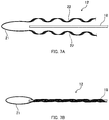
- Fig. 7A is a diagram illustrating a structure of the end portion gripping grip 19 according to the second embodiment of the present invention.
- the end portion gripping grip 19 includes a folded portion 21 and two grip portions 22.
- the two grip portions 22 are formed by being coupled to each other with the folded portion 21.
- Fig. 7B is a diagram illustrating a detailed structure of the end portion gripping grip 19 in the case of gripping the leading supporting wire 18.
- the two grip parts 19 of the gripping grip 12 are wound around the leading supporting wire 18 in a spiral shape to grip the leading supporting wire 18.
- a winding method is similar to that described with reference to Fig. 5A to Fig. 5C (first embodiment) .
- the loop formed by the folded portion 21 is, for example, hooked to an anchor firmly fixed to the utility pole R or the subscriber's house Q to lock the leading supporting wire 18 to the utility pole R. (Refer to Figs. 6A and 6B .)
- Fig. 8A illustrates a longitudinal-direction cross-sectional view with no tension being applied in the case of gripping a supporting wire part by using a gripping grip.
- Fig. 8B illustrates a longitudinal-direction cross-sectional view in a case that tension is applied and hence separation occurs at an interface.
- the supporting wire part 2 between utility poles forms a line sagging in the gravity direction instead of forming an ideal straight line.
- the above-described force of separation locally appears at portions at or near an area of the supporting wire part 2 to which the pressure force by the gripping grip 12 is applied, and this makes it easier for separation to occur.
- Fig. 8B illustrates a phenomenon in which separation at the interface occurs at or near the area to which the pressure force by the gripping grip 12 is applied.
- the pressure force acts in the directions of canceling the force of separation, which prevents the separation at the interface.
- the portion where the separation at the interface occurs is not always positioned at or near the area to which the pressure force by the gripping grip 12 is applied. There is a possibility that separation at an interface occurs also at any portions in the area to which the pressure force by the gripping grip 12 is not applied.
- the gripping grip 12 comes in direct contact with the supporting wire 5. Since the supporting wire 5 is formed of a nonmetallic material, such as glass fiber reinforced plastic (GFRP), for example, this contact of the gripping grip 12 easily causes breakage in comparison with the case that the supporting wire 5 is formed using a steel wire or the like.
- GFRP glass fiber reinforced plastic
- Fig. 9 is a diagram for illustrating a test mechanism 21 for measuring an adhesion force of an outer sheath and a supporting wire.
- the test mechanism 21 is a mechanism in which part of the supporting wire 5 is covered with the outer sheath 6A, only the supporting wire 5 is pulled with the tension T in the tension direction in Fig. 9 through a fixing plate 22 with a hole, and a load at the time of pulling out is measured by a load cell 23. This load at the time of pulling out is assumed as adhesion force below.
- each prototype optical fiber cable had the supporting wire 5 of 4.5 mm in diameter and diameter of the optical fiber cable with the supporting wire 5 covered with the outer sheath 6A was 6.0 mm.
- the length of the outer sheath 6A for covering in the test mechanism 21 was configured to be 10 mm, and the tensile force with pull-out rate of 50 mm/minute was applied, to measure the load.
- the adhesion force of the outer sheath 6A and the supporting wire 5 was assumed to be reduced at high temperature, measurement was performed at a plurality of time points in the environment at the air temperature of 85 degree Celsius in the adhesion force measurement test. Table 1 presents the result of the adhesion force measurement test.
Landscapes
- Physics & Mathematics (AREA)
- General Physics & Mathematics (AREA)
- Optics & Photonics (AREA)
- Light Guides In General And Applications Therefor (AREA)
Abstract


Description
- The present invention relates to a method for gripping an optical fiber cable and an optical fiber cable gripping tool.
- Recent years have seen the widespread use of fiber to the home (FTTH) services for providing high-speed communication services by directly connecting communication providers and subscribers via optical fibers. As an optical fiber cable extended from a communication provider and installed so as to bridge utility poles, an aerial optical fiber cable installed with a supporting wire anchored to utility poles or the like is known.
- Relating to such an optical fiber cable,
Patent Literature 1 discloses an optical fiber cable having a self-supporting structure with a supporting wire formed using a steel wire and further covered with an outer sheath. Moreover,Patent Literature 2 discloses a technique for locking, using S metal fitting having a function of anchoring an aerial optical fiber cable, an end of a supporting wire separated from the optical fiber cable to an anchor of the S metal fitting by winding the end portion around the anchor in a crossed manner. -
- Patent Literature 1:
JP 2014-219494A - Patent Literature 2:
JP 2000-41325A - For the purpose of suppressing electromagnetic induction, there is a growing demand for the introduction of supporting wires made of a material other than metal, a so-called nonmetallic material, in place of steel wires as used in
Patent Literature 1. In the case of a supporting wire using a steel wire, the supporting wire is anchored to utility poles or the like by stripping an outer sheath covering the supporting wire off. However, in the case of a nonmetallic material supporting wire, there is a possibility of breakage of the supporting wire when a gripping tool for anchoring the supporting wire comes directly into contact with the supporting wire, and hence an anchoring method as that described above has not been employed. Moreover, in a case of locking a nonmetallic material supporting wire by winding the supporting wire around an anchor of S metal fitting as inPatent Literature 2, there is a possibility of fracture of the supporting wire. In view of these, there is a need for a method for anchoring a nonmetallic material supporting wire while suppressing breakage of the supporting wire. - An objective of the present invention is to anchor a nonmetallic material supporting wire while suppressing breakage of the supporting wire.
- A primary aspect of the invention for achieving the aforementioned objective is a method for gripping an optical fiber cable by using a gripping member, the optical fiber cable including a main body part including an optical fiber and a supporting wire part, the supporting wire part including a supporting wire made of a material other than metal and an outer sheath covering the supporting wire, the method including gripping the supporting wire part by tightening the gripping member around the supporting wire part while the supporting wire remains covered with the outer sheath.
- Other features of the present invention are made clear by the following description and the drawings.
- With the present invention, it is possible to anchor a nonmetallic material supporting wire while suppressing breakage of the supporting wire.
-
-
Fig. 1 is a cross-sectional view of anoptical fiber cable 1. -
Fig. 2 is a diagram schematically illustrating a gripping structure of theoptical fiber cable 1 according to a first embodiment of the present invention. -
Fig. 3 is a cross-sectional view of agripping part 11 seen in a longitudinal direction of a supportingwire part 2. -
Fig. 4 is a diagram for illustrating a detailed structure of grippinggrips 12. -
Fig. 5A to Fig. 5C are diagrams illustrating a method for winding thegripping grips 12 illustrated inFig. 4 around the supportingwire part 2. -
Fig. 6A and Fig. 6B are diagrams schematically illustrating a gripping structure of anoptical fiber cable 1 according to a second embodiment of the present invention. -
Fig. 7A is a diagram illustrating a structure of an endportion gripping grip 19 according to the second embodiment of the present invention.Fig. 7B is a diagram illustrating a detailed structure of the endportion gripping grip 19 in the case of gripping a leading supportingwire 18. -
Fig. 8A illustrates a longitudinal-direction cross-sectional view with no tension being applied in the case of gripping a supporting wire part by using a gripping grip.Fig. 8B illustrates a longitudinal-direction cross-sectional view in a case that tension is applied and hence separation occurs at an interface. -
Fig. 9 is a diagram for explaining atest mechanism 21 for measuring adhesion force of an outer sheath and a supporting wire. - At least the following matters are made clear from the following description and the drawings.
- Disclosed is a method for gripping an optical fiber cable by using a gripping member, the optical fiber cable including a main body part including an optical fiber and a supporting wire part, the supporting wire part including a supporting wire made of a material other than metal and an outer sheath covering the supporting wire, the method including gripping the supporting wire part by tightening the gripping member around the supporting wire part while the supporting wire remains covered with the outer sheath. With such a method for gripping an optical fiber cable, it is possible to anchor the nonmetallic material supporting wire while suppressing breakage of the supporting wire.
- It is preferable that the gripping member is tightened by being wound around the supporting wire part in a spiral shape. In this way, it is possible for the gripping member to grip the supporting wire part more tightly.
- It is preferable that the supporting wire is made of glass fiber reinforced plastic. The method is particularly advantageous in such a case.
- It is preferable that a non-slip material is provided between the gripping member and the outer sheath. In this way, the gripping member comes off less easily in a state of the gripping member gripping the supporting wire part.
- It is preferable that the gripping member grips the supporting wire part by being tightened around the supporting wire part to a degree not to squeeze the outer sheath. In this way, it is possible to suppress breakage of the supporting wire due to the outer sheath being squeezed.
- It is preferable that neck parts are provided intermittently, each of the neck parts being formed by the outer sheath integrally covering the main body part and the supporting wire to couple the main body part and the supporting wire together. In this way, it is possible to suppress breakage of the supporting wire due to wind load even in aerial environment with a long span.
- It is preferable that the supporting wire part is gripped at a fixed structure by a separated part not coupling the main body part and the supporting wire part. In this way, only a supporting wire is gripped, and hence it is possible to suppress breakage of the optical fiber in the main body part.
- It is preferable that the main body part is sagging down with respect to the supporting wire part. In this way, even when tensile force is applied to the supporting wire, it is possible to suppress breakage of the optical fiber.
- It is preferable that, given that a diameter of the supporting wire is D, adhesion force F of the outer sheath and the supporting wire is 1.77πD [N/mm] or greater. In this way, even when tensile force is applied to the supporting wire in aerial environment, it is possible to suppress occurrence of separation of the outer sheath and the supporting wire at a boundary face.
- Basic Structure of Optical Fiber Cable 1:
Fig. 1 is a cross-sectional view of anoptical fiber cable 1. Theoptical fiber cable 1 is an aerial optical fiber cable having a self-supporting structure and being used in the case of installing theoptical fiber cable 1 to bridge utility poles in FTTH. Alternatively, theoptical fiber cable 1 may be an optical fiber drop cable branching off from an aerial optical fiber cable and leading an optical fiber(s) to a subscriber' s house. Theoptical fiber cable 1 includes a supportingwire part 2, amain body part 3, and aneck part 4. Theoptical fiber cable 1 has a structure in which the supportingwire part 2 and themain body part 3 are coupled together with theneck part 4 provided therebetween. - The supporting
wire part 2 is an aerial hanger wire. The supportingwire part 2 includes a supportingwire 5 and anouter sheath 6A. - The supporting
wire 5 is formed of a material other than metal, i.e., a so-called nonmetallic material. As a nonmetallic material, fiber reinforced plastic (FRP), such as glass fiber reinforced plastic (GFRP), aramid fiber reinforced plastic reinforced with Kevlar (registered trademark) (KFRP), or polyethylene fiber reinforced plastic reinforced with polyethylene fibers, or the like, for example. Alternatively, a combination of a fibrous tensile member, such as glass fibers, aramid fibers, or polyethylene fibers, and any of the above-described kinds of fiber reinforced plastic (FRP), may be used. - The
outer sheath 6A is a covering material covering the supportingwire 5. Theouter sheath 6A is formed of thermoplastic resin. As the thermoplastic resin, a material generally used for an optical fiber cable, such as a polyethylene, polypropylene, polystyrene, or polyvinyl chloride, is used, for example. - The
main body part 3 includesoptical fibers 9, a pair oftensile members 7, a pair ofseparators 8, and anouter sheath 6B. Theoptical fibers 9, the pair oftensile members 7, and the pair ofseparators 8 are arranged in a positional relationship as illustrated inFig. 1 . Theoptical fibers 9 and the pair oftensile members 7 are arranged in parallel with each other in a longitudinal direction. Note that the structure of themain body part 3 is not limited to this as long as theoptical fibers 9 are included. - The
optical fibers 9 are optical signal transmission lines, and optical fiber is a generic term for a secondary coated optical fiber, a primary coated optical fiber, an optical fiber cord, and the like. Theoptical fibers 9 may be formed using an intermittently connected optical fiber ribbon. Thus, intermittently connected optical fiber ribbons can be rolled up into a cylindrical form (a bundle), or folded up, and the multitude ofoptical fibers 9 can be bundled with high density. Furthermore, using such an intermittently connected optical fiber ribbon makes it easy for one or a plurality of optical fibers to be extracted in mid-span branching. - The pair of
tensile members 7 has a function of resisting tension applied in the longitudinal direction of theoptical fibers 9, to prevent theoptical fibers 9 from being stretched more than necessary. The pair oftensile members 7 is arranged on the outer sides of right and left ends of the pair ofseparators 8. The pair oftensile members 7 may be formed of the same nonmetallic material as that of the supportingwire 5 or may be formed using steel wires. - The pair of
separators 8 has a function of separating theoptical fibers 9 and theouter sheath 6B. The pair ofseparators 8 surrounds theoptical fibers 9 to prevent the material of theouter sheath 6B from adhering to the optical fibers in a process of manufacturing theoptical fiber cable 1. The pair ofseparators 8 is formed of a material having a melting point higher than that of the material of theouter sheath 6B. As the material of the pair ofseparators 8, a nylon flat string is used, for example. This prevents theoptical fibers 9 from being thermally fused with the material of theouter sheath 6B even in the case of extrusion covering by extruding the material of theouter sheath 6B to cover theoptical fibers 9, the pair oftensile members 7, and the pair ofseparators 8. - The
outer sheath 6B may be formed of the same material as that of theouter sheath 6A or may be formed of a different material. - As illustrated in
Fig. 1 , the cross sectional shape of themain body part 3 including theouter sheath 6B is substantially rectangular. Themain body part 3 includes, at each long side of the rectangle,notches 10 each formed to have a V-shaped cross section. Twonotches 10 are formed at each side. - The
notches 10 are provided so as to make it easy to extract theoptical fibers 9 by splitting and cutting themain body part 3. Although thenotches 10 are not necessarily formed in themain body part 3, thenotches 10 are preferably formed. - The supporting
wire part 2 and themain body part 3 can be separated by cutting theneck part 4. Theneck part 4 can be formed of the same material as that of theouter sheath 6A and theouter sheath 6B. Alternatively, theneck part 4, theouter sheath 6A, and theouter sheath 6B may be integrally formed of the same material. - Note that the
optical fiber cable 1 is not limited to the above-described structure and may be any of various structures. For example, theoptical fibers 9 may include 8 cores to 48 cores or may include 48 cores or more. - Gripping Structure of Optical Fiber Cable 1:
Fig. 2 is a diagram schematically illustrating a gripping structure of theoptical fiber cable 1 according to the first embodiment of the present invention. Described below is a structure for gripping theoptical fiber cable 1 at utility poles P to install theoptical fiber cable 1 to bridge the utility poles with a long span. - The supporting
wire part 2 and themain body part 3 are coupled with a plurality ofneck parts 4 provided intermittently in the longitudinal direction. As described above, the coupling with theneck parts 4 may be provided by integrally forming theneck parts 4, theouter sheath 6A, and theouter sheath 6B of the same material to couple the supportingwire part 2 and themain body part 3. At a portion between each pairedadjacent neck parts support wire part 2 and themain body part 3 are separated. At each position where the supportingwire part 2 and themain body part 3 are separated, agripping part 11 is provided to grip only the supportingwire part 2 at the corresponding utility pole P. - At each position where the supporting
wire part 2 and themain body part 3 are separated, themain body part 3 is provided in such a manner as to sag down with respect to the supportingwire part 2 forming a serpentine course. This forms a space between the supportingwire part 2 and themain body part 3, which can reduce the wind load imposed on the entireoptical fiber cable 1. - An example of the
optical fiber cable 1 includes theneck parts 4 each being 40 mm in length and the separated sections each being 250 mm or 550 mm in length (pitch of the neck parts 4) in the longitudinal direction of the supporting wire part, with the distance between the utility poles on the order of several meters to 50 m. Note that, however, these values may be appropriately changeable by taking account of usage environment, such as the wind load imposed on theoptical fiber cable 1. - The
gripping part 11 includes agripping grip 12 and a fixingmember 13. Thegripping part 11 has a structure in which the grippinggrip 12 grips the supportingwire part 2 and the fixingmember 13 fixes the supportingwire part 2 gripped by the grippinggrip 12 to the corresponding utility pole P. -
Fig. 3 is a cross-sectional view of thegripping part 11 seen in the longitudinal direction of the supportingwire part 2. The fixingmember 13 included in thegripping part 11 includes a pair ofcovers - The
cover 14A is firmly fixed to the utility pole P. Thecover 14A and thecover 14B are provided so as to cover the supportingwire unit 2 and the grippinggrip 12 and are fastened to each other by thefixture 15. In this way, the supportingwire part 2 and the grippinggrip 12 are fixed to the utility pole P. - The gripping
grip 12 is provided to grip the supportingwire part 2 and wind around the circumference of the supportingwire part 2. A detailed structure of the grippinggrip 12 will be described later. Here, the grippinggrip 12 is attached to the circumference of the supportingwire part 2 with the supportingwire 5 remaining covered with theouter sheath 6A. This can prevent damage to a surface of the supportingwire 5 due to the grippinggrip 12 being directly attached to the supportingwire 5 not covered with theouter sheath 6A. Hence, it is possible to anchor the nonmetallicmaterial supporting wire 5 while suppressing breakage of the supportingwire 5. In addition, since there is no need to strip off theouter sheath 6A, different from the case of anchoring a supporting wire of a steel wire, it is possible to perform an anchoring operation efficiently. - To prevent damage to the surface of the supporting
wire 5, the pressure force of the grippinggrip 12 is preferably adjusted to such an extent as to cause no squeezing (including breakage) of theouter sheath 6A. -
Fig. 4 is a diagram for illustrating a detailed structure of gripping grips 12. In the present embodiment, a structure in which threegripping grips 12 are wound around the supportingwire part 2 in a spiral shape to grip the supportingwire part 2 is shown. Note that the number ofgripping grips 12 for gripping the one supportingwire part 2 is not intended to be limited to three and may be any other number. - Each gripping
grip 12 includes a plurality ofwires 16. For eachwire 16, a galvanized steel wire, a zinc-aluminum alloy plated steel wire, or the like is used. The plurality ofwires 16 are placed side by side, bonded to each other, and further wound in a spiral shape. A friction material for increasing frictional force may be applied to surfaces, of the plurality ofwires 16 wound in a spiral shape, that are to come in contact with the supportingwire part 2. As the friction material, fine-grained sand, grains of glass, or the like, for example may be used. - Each gripping
grip 12 illustrated inFig. 4 includes five wires. However, the number of wires constituting the gripping grip is not intended to be limited to five, and the grippinggrip 12 may be constituted of one flat wire. -
Fig. 5A to Fig. 5C are diagrams illustrating a method for winding thegripping grips 12 illustrated inFig. 4 around the supportingwire part 2. In the following description, thegripping grips 12 may be distinguished from each other based on alphabets (A to C) attached to thegripping grips 12 for explanation. - First, as illustrated in
Fig. 5A , thegripping grip 12A is wound around the supportingwire part 2 separated from themain body part 3. In this stage, thegripping grip 12A is wound while the winding pitch for thegripping grip 12A is adjusted, so as to keep spaces for thegripping grip 12B and thegripping grip 12C to be wound later. - Next, as illustrated in
Fig. 5B , thegripping grip 12B is wound to be adjacent to thegripping grip 12A.Fig. 5B presents a state halfway through the winding of thegripping grip 12B. - Subsequently, as illustrated in
Fig. 5C , thegripping grip 12C is wound to be adjacent to thegripping grip 12B. Thegripping grip 12A to thegripping grip 12C are tightened by being pulled to opposite ends thereof to be stretched and thereby grip the supportingwire part 2. Finally, thegripping grips 12A to thegripping grip 12C are fixed to the supportingwire part 2 with an unillustrated fixing member, such as a tape. - For the above-described
gripping part 11, a description has been given of the method for tightening thegripping grips 12 around the supportingwire part 2 by winding thegripping grips 12 around the supportingwire part 2 in a spiral shape. The tightening method is not limited to this, however, and may be longitudinal tightening or tightening with winding in a manner different from a spiral shape. - Gripping Structure of Optical Fiber Cable 1 (Another Example):
For theoptical fiber cable 1 of the first embodiment, a description has been given of the case where the supportingwire part 2 is gripped at each utility pole in installing theoptical fiber cable 1 to bridge the utility poles. For an optical cable described in the present embodiment, it is possible to grip the optical fiber cable in a similar method even in the case of the optical fiber cable being an optical fiber drop cable for branching the optical fiber cable to be led to a subscriber's house or the like. -
Fig. 6A and Fig. 6B are diagrams schematically illustrating gripping structures of anoptical fiber cable 1 according to the second embodiment of the present invention.Fig. 6A is a diagram for illustrating a case of branching optical fiber(s) in a utility pole mountedtype branch closure 17A and leading the optical fiber (s) to a subscriber's house Q. Meanwhile,Fig. 6B is a diagram for illustrating a case of branching optical fiber(s) in a supporting wire hangingtype branch closure 17B and leading the optical fiber(s) to the subscriber's house Q. - In
Fig. 6A , thebranch closure 17A is provided to a utility pole R. Thebranch closure 17A is an enclosure that, in the case of connecting, branching, pulling down, and the like an optical fiber cable, anchors the optical fiber cable therein and accommodates a connecting point. In theoptical fiber cable 1 described in the present embodiment,optical fibers 9 of amain body part 3 are partially branched in thebranch closure 17A, and the branched part is led as a newmain body part 3A into the subscriber's house Q. - After the branching, the
main body part 3A is led, while being supported by a leading supportingwire 18, to the subscriber's house Q through a leadinghole 20 formed at the subscriber's house Q. The leading supportingwire 18 is, as the supportingwire part 2 described above (first embodiment), formed with a supporting wire formed of a nonmetallic material and further covered with an outer sheath (not illustrated) . The leading supportingwire 18 is anchored by endportion gripping grips 19, and one end of the leading supportingwire 18 is fixed to the utility pole R while the other end of the leading supportingwire 18 is fixed to a wall of the subscriber's house Q. - In
Fig. 6B , thebranch closure 17B is provided to the supportingwire part 2. Other parts of the structure are similar to those described inFig. 6A . -
Fig. 7A is a diagram illustrating a structure of the endportion gripping grip 19 according to the second embodiment of the present invention. The endportion gripping grip 19 includes a foldedportion 21 and twogrip portions 22. The twogrip portions 22 are formed by being coupled to each other with the foldedportion 21. -
Fig. 7B is a diagram illustrating a detailed structure of the endportion gripping grip 19 in the case of gripping the leading supportingwire 18. The twogrip parts 19 of the grippinggrip 12 are wound around the leading supportingwire 18 in a spiral shape to grip the leading supportingwire 18. A winding method is similar to that described with reference toFig. 5A to Fig. 5C (first embodiment) . The loop formed by the foldedportion 21 is, for example, hooked to an anchor firmly fixed to the utility pole R or the subscriber's house Q to lock the leading supportingwire 18 to the utility pole R. (Refer toFigs. 6A and 6B .) - In the first embodiment and the second embodiment, descriptions have been given of gripping a supporting wire (supporting wire part) remaining covered with an outer sheath, by using gripping grips. In such a case, however, when tension is applied to the supporting wire part in the longitudinal direction in an aerial environment, separation may occur at a boundary face between the outer sheath and the supporting wire, and the separation may cause breakage of the outer sheath in some cases. This respect will be described below. In the following description, the boundary face between the outer sheath and the supporting wire may be simply referred to as an "interface".
-
Fig. 8A illustrates a longitudinal-direction cross-sectional view with no tension being applied in the case of gripping a supporting wire part by using a gripping grip.Fig. 8B illustrates a longitudinal-direction cross-sectional view in a case that tension is applied and hence separation occurs at an interface. - First, in a state where no tension is applied, almost no separation occurs at the interface. This is because, although pressure force by the gripping
grip 12 is applied to the supportingwire 5 covered with theouter sheath 6A (supporting wire part 2), the force scarcely acts in the direction of separation at the interface. - However, as illustrated in
Fig. 8B , tension T is applied in the tension directions of the supportingwire part 2 in the aerial environment. In this state, theouter sheath 6A with which the grippinggrip 12 is in contact is pulled in the directions of the tension T and stretches in the longitudinal direction. Consequently, the thickness of theouter sheath 6A is reduced with the stretch, and this acts as force that brings theouter sheath 6A to separate from the supportingwire 5. - Since the gripping grip is not in direct contact with the supporting
wire 5, pulling of the supportingwire 5 in the directions of the tension T is not so strong as that for theouter sheath 6A. This causes strain according to the degrees of stretch of theouter sheath 6A and the supportingwire 5. The shear force between theouter sheath 6A and the supportingwire 5 due to the distortion also acts as a force that causes theouter sheath 6A to separate from the supportingwire 5. - In actual aerial environment, the supporting
wire part 2 between utility poles forms a line sagging in the gravity direction instead of forming an ideal straight line. In this situation, the above-described force of separation locally appears at portions at or near an area of the supportingwire part 2 to which the pressure force by the grippinggrip 12 is applied, and this makes it easier for separation to occur. - In a case that the force of separation exceeds the force of bonding of the
outer sheath 6A and the supportingwire 5, separation at the interface occurs.Fig. 8B illustrates a phenomenon in which separation at the interface occurs at or near the area to which the pressure force by the grippinggrip 12 is applied. - In the area to which the pressure force by the gripping
grip 12 is applied, the pressure force acts in the directions of canceling the force of separation, which prevents the separation at the interface. The portion where the separation at the interface occurs is not always positioned at or near the area to which the pressure force by the grippinggrip 12 is applied. There is a possibility that separation at an interface occurs also at any portions in the area to which the pressure force by the grippinggrip 12 is not applied. - This separation at the interface causes breakage of the
outer sheath 6A. Due to the breakage of theouter sheath 6A, the grippinggrip 12 comes in direct contact with the supportingwire 5. Since the supportingwire 5 is formed of a nonmetallic material, such as glass fiber reinforced plastic (GFRP), for example, this contact of the grippinggrip 12 easily causes breakage in comparison with the case that the supportingwire 5 is formed using a steel wire or the like. - Evaluation of Adhesion Force of Outer Sheath and Supporting Wire:
In a case that the adhesion force of the outer sheath and the supporting wire is at or smaller than a certain degree, separation at the interface occurs. By taking this into account, first, a plurality of optical fiber cables were created, and the adhesion force of the outer sheath and the supporting wire of each optical fiber cable was measured. Then, a tensile test was carried out with a gripping grip being attached to each optical fiber cable. -
Fig. 9 is a diagram for illustrating atest mechanism 21 for measuring an adhesion force of an outer sheath and a supporting wire. Thetest mechanism 21 is a mechanism in which part of the supportingwire 5 is covered with theouter sheath 6A, only the supportingwire 5 is pulled with the tension T in the tension direction inFig. 9 through a fixingplate 22 with a hole, and a load at the time of pulling out is measured by aload cell 23. This load at the time of pulling out is assumed as adhesion force below. - In the adhesion force measurement test, each prototype optical fiber cable had the supporting
wire 5 of 4.5 mm in diameter and diameter of the optical fiber cable with the supportingwire 5 covered with theouter sheath 6A was 6.0 mm. The length of theouter sheath 6A for covering in thetest mechanism 21 was configured to be 10 mm, and the tensile force with pull-out rate of 50 mm/minute was applied, to measure the load. Moreover, since the adhesion force of theouter sheath 6A and the supportingwire 5 was assumed to be reduced at high temperature, measurement was performed at a plurality of time points in the environment at the air temperature of 85 degree Celsius in the adhesion force measurement test. Table 1 presents the result of the adhesion force measurement test.[Table 1] [N/10mm] Time of application in 85° C [hours] 0 100 300 500 Prototype cable 1463 440 349 328 Prototype cable 2443 429 375 348 Prototype cable 3391 276 230 188 Prototype cable 4327 343 320 282 Prototype cable 5308 302 260 252 - Five prototype cables were created in total, and the adhesion force was measured using each of the prototype cables in the environment with the air temperature of 85 degrees Celsius at time points after the elapse of 0 hour, 100 hours, 300 hours, and 500 hours. As presented in the result in Table 1, the adhesion force is the smallest at the time point after the elapse of 500 hours for any of the prototype cables, and it is demonstrated that the decrease of the adhesion force of
prototype cable 3 in time course among all is significant. - Next, the tensile test was carried out by attaching the
gripping grips 12 at both ends of each of the cables same asprototype cables 1 to 5. In the tensile test, the load was measured at the time when exposure of the supportingwire 5 was confirmed due to breakage of theouter sheath 6A. In the following, the load at the time of breakage is assumed as breaking load.[Table 2] [N/mm] Time of application in 85° C [hours] 0 500 Prototype cable 19853 7323 Prototype cable 29135 7251 Prototype cable 37634 3058 Prototype cable 47036 5846 Prototype cable 56943 5321 - From the result in Table 2, the breaking load of
only prototype cable 3 after the elapse of 500 hours is significantly small in comparison with the other prototype cables. Moreover, although the diameter of each prototype cable covered with theouter sheath 6A was designed on the assumption that the maximum wind load (including the time of ice accretion) of approximately 3200 N was to be applied, this breaking load is still small even in consideration of the above . Hence,prototype cable 3 was evaluated as being disqualified, andother prototype cables - The above results in Table 1 and Table 2 demonstrate that the smallest adhesion force among
qualified prototype cables prototype cable 5 after the elapse of 500 hours) . It is apparent that the adhesion force of theouter sheath 6A and the supportingwire 5 depends on the surface area of the supportingwire 5. From these results, provided that the diameter of the supportingwire 5 is D, necessary adhesion force F (N/mm) can be expressed by the following expression.
[Math. 1]
- The above-described embodiments are intended to facilitate the understanding of the present invention and are not to be construed as limiting the present invention. It is apparent that modifications and improvements can be made to the present invention without departing from the gist of the present invention, and equivalents of the present invention are included in the present invention.
-
- 1: Optical fiber cable;
- 2: Supporting wire part;
- 3, 3A: Main body part;
- 4: Neck part;
- 5: Supporting wire;
- 6A, 6B: Outer sheath;
- 7: Tensile member;
- 8: Separator;
- 9: Optical fiber;
- 10: Notch;
- 11: Gripping part;
- 12: Gripping grip;
- 13: Fixing member;
- 14: Cover;
- 15: Fixture;
- 16: Element wire;
- 17A, 17B: Branch closure;
- 18: Leading supporting wire;
- 19: End portion gripping grip;
- 20: Leading hole;
- 21: Test mechanism;
- 22: Fixing plate with hole;
- 23: Load cell.
Claims (9)
- A method for gripping an optical fiber cable by using a gripping member, the optical fiber cable including a main body part including an optical fiber and a supporting wire part,
the supporting wire part including a supporting wire made of a material other than metal and an outer sheath covering the supporting wire, the method comprising
gripping the supporting wire part by tightening the gripping member around the supporting wire part while the supporting wire remains covered with the outer sheath. - The method for gripping the optical fiber cable according to claim 1, wherein the gripping member is tightened by being wound around the supporting wire part in a spiral shape.
- The method for gripping the optical fiber cable according to claim 1, wherein the supporting wire is made of glass fiber reinforced plastic.
- The method for gripping the optical fiber cable according to claim 1, wherein a friction material is provided between the gripping member and the outer sheath.
- The method for gripping the optical fiber cable according to claim 1, wherein the gripping member grips the supporting wire part by being tightened around the supporting wire part to a degree not to squeeze the outer sheath.
- The method for gripping the optical fiber cable according to claim 1, wherein neck parts are provided intermittently, each of the neck parts being formed by the outer sheath integrally covering the main body part and the supporting wire to couple the main body part and the supporting wire together.
- The method for gripping the optical fiber cable according to claim 5, wherein the supporting wire part is gripped at a fixed structure by a separated part not coupling the main body part and the supporting wire part.
- The method for gripping the optical fiber cable according to claim 6, wherein the main body part is sagging down with respect to the supporting wire part.
- The method for gripping the optical fiber cable according to claim 1, wherein
given that a diameter of the supporting wire is D,
adhesion force F of the outer sheath and the supporting wire is 1.77nD[N/mm] or greater.
Applications Claiming Priority (2)
| Application Number | Priority Date | Filing Date | Title |
|---|---|---|---|
| JP2016124561A JP2017227791A (en) | 2016-06-23 | 2016-06-23 | Holding method for optical fiber cable, optical fiber cable, and optical fiber cable with component for holding |
| PCT/JP2017/005505 WO2017221454A1 (en) | 2016-06-23 | 2017-02-15 | Method for gripping optical fiber cable, and optical fiber cable gripping tool |
Publications (2)
| Publication Number | Publication Date |
|---|---|
| EP3451037A1 true EP3451037A1 (en) | 2019-03-06 |
| EP3451037A4 EP3451037A4 (en) | 2019-12-18 |
Family
ID=60783971
Family Applications (1)
| Application Number | Title | Priority Date | Filing Date |
|---|---|---|---|
| EP17814926.6A Withdrawn EP3451037A4 (en) | 2016-06-23 | 2017-02-15 | FIBER OPTIC CABLE GRIPPING METHOD, AND FIBER OPTIC CABLE GRIPPING TOOL |
Country Status (5)
| Country | Link |
|---|---|
| EP (1) | EP3451037A4 (en) |
| JP (1) | JP2017227791A (en) |
| CN (1) | CN109154707A (en) |
| TW (1) | TWI641886B (en) |
| WO (1) | WO2017221454A1 (en) |
Cited By (2)
| Publication number | Priority date | Publication date | Assignee | Title |
|---|---|---|---|---|
| US11886029B2 (en) | 2021-03-10 | 2024-01-30 | Afl Telecommunications Llc | Systems and methods of managing cables in telecommunication systems |
| US12172588B2 (en) | 2019-05-30 | 2024-12-24 | Autonetworks Technologies, Ltd. | Wiring member |
Family Cites Families (15)
| Publication number | Priority date | Publication date | Assignee | Title |
|---|---|---|---|---|
| JPS5995304U (en) * | 1982-12-18 | 1984-06-28 | 東北電力株式会社 | Non-metallic self-supporting aerial optical cable |
| US4852965A (en) * | 1987-02-27 | 1989-08-01 | American Telephone And Telegraph Company At&T Bell Laboratories | Composite service and distribution communications media |
| US5043037A (en) * | 1989-11-22 | 1991-08-27 | Sumitomo Electric Fiber Optics Corporation | Method for making high strain aerial fiber optic cable |
| JP2513737Y2 (en) * | 1991-02-08 | 1996-10-09 | 日本大洋海底電線株式会社 | Self-supporting open coaxial cable |
| JPH08265941A (en) * | 1995-03-20 | 1996-10-11 | P L P:Kk | Sz stranded winding grip and production thereof |
| US6356690B1 (en) * | 1999-10-20 | 2002-03-12 | Corning Cable Systems Llc | Self-supporting fiber optic cable |
| JP2001328189A (en) * | 2000-05-23 | 2001-11-27 | Ube Nitto Kasei Co Ltd | Fiber-reinforced synthetic resin linear material |
| JP4593027B2 (en) * | 2001-07-19 | 2010-12-08 | 株式会社フジクラ | Self-supporting aerial optical cable and its terminal retaining structure |
| US6728455B2 (en) * | 2001-09-04 | 2004-04-27 | Fujikura Ltd. | Optical fiber drop cable and manufacturing method thereof |
| JP2003090943A (en) * | 2001-09-19 | 2003-03-28 | Fujikura Ltd | Optical fiber cable and method of retaining optical fiber cable |
| JP2004309648A (en) * | 2003-04-03 | 2004-11-04 | Sumitomo Electric Ind Ltd | Optical fiber cable manufacturing method |
| TWI252939B (en) * | 2004-05-31 | 2006-04-11 | Kaiphone Comm Co Ltd | Optical fiber patch cord |
| US7218821B2 (en) * | 2004-08-20 | 2007-05-15 | Furukawa Electric North America Inc. | Optical fiber cables |
| JP2007148121A (en) * | 2005-11-29 | 2007-06-14 | Sumitomo Denko Steel Wire Kk | Optical fiber cable holder, optical fiber cable retaining structure, and optical fiber cable retaining method |
| US8203074B2 (en) * | 2006-10-25 | 2012-06-19 | Advanced Technology Holdings Ltd. | Messenger supported overhead cable for electrical transmission |
-
2016
- 2016-06-23 JP JP2016124561A patent/JP2017227791A/en active Pending
-
2017
- 2017-02-15 WO PCT/JP2017/005505 patent/WO2017221454A1/en not_active Ceased
- 2017-02-15 EP EP17814926.6A patent/EP3451037A4/en not_active Withdrawn
- 2017-02-15 CN CN201780031207.7A patent/CN109154707A/en active Pending
- 2017-03-01 TW TW106106678A patent/TWI641886B/en not_active IP Right Cessation
Cited By (3)
| Publication number | Priority date | Publication date | Assignee | Title |
|---|---|---|---|---|
| US12172588B2 (en) | 2019-05-30 | 2024-12-24 | Autonetworks Technologies, Ltd. | Wiring member |
| US11886029B2 (en) | 2021-03-10 | 2024-01-30 | Afl Telecommunications Llc | Systems and methods of managing cables in telecommunication systems |
| US12306452B2 (en) | 2021-03-10 | 2025-05-20 | Afl Telecommunications Llc | Systems and methods of managing cables in telecommunication systems |
Also Published As
| Publication number | Publication date |
|---|---|
| TW201800792A (en) | 2018-01-01 |
| CN109154707A (en) | 2019-01-04 |
| EP3451037A4 (en) | 2019-12-18 |
| JP2017227791A (en) | 2017-12-28 |
| TWI641886B (en) | 2018-11-21 |
| WO2017221454A1 (en) | 2017-12-28 |
Similar Documents
| Publication | Publication Date | Title |
|---|---|---|
| CN1589417B (en) | Optical fibre drop cables | |
| JP2005510027A5 (en) | ||
| JP2006058892A (en) | Fiber optic cable | |
| US7672556B2 (en) | Flat design composite drop fiber cable with mid-span access capability | |
| US20190011657A1 (en) | Mechanical fuse for use with overhead telecommunications cable | |
| US20130077922A1 (en) | Double jacket optical fiber cables | |
| US6775445B2 (en) | Optical fiber drop cable | |
| TWI641886B (en) | Method for holding optical fiber cable and optical fiber cable | |
| CN111025506A (en) | An overhead optical cable laying hardware and an overhead optical cable that can be laid using the same | |
| JP4205523B2 (en) | Drop optical fiber cable | |
| CN101988979B (en) | Fiber optic drop cable assembly for deployment on building walls | |
| US10557568B2 (en) | Multi-sided cable clamps | |
| RU112490U1 (en) | COMBINED WIRE | |
| JP2000131571A (en) | Fiber optic cable | |
| EP3214473B1 (en) | Support structure for an optical fiber cable | |
| JP2009229786A (en) | Optical fiber cable | |
| JP7278485B2 (en) | Bundled suspension wire | |
| KR20110039837A (en) | Fiber optic cable | |
| JP5014460B2 (en) | Fiber optic cable | |
| RU143787U1 (en) | DEVICE FOR TAPING A NAVIVAL OPTICAL CABLE FROM A CARRYING ELEMENT OR HARNESS | |
| US20240027718A1 (en) | Supporting and routing drop lines from an all-dielectric selfsupporting (adss) fiber optic trunk cable | |
| JPH10104477A (en) | Optical cable for outdoor aerial assembly | |
| JP4388006B2 (en) | Optical cable | |
| JP2004070230A (en) | Optical cable | |
| KR100999840B1 (en) | How to install waterproof optical cable junction box |
Legal Events
| Date | Code | Title | Description |
|---|---|---|---|
| STAA | Information on the status of an ep patent application or granted ep patent |
Free format text: STATUS: THE INTERNATIONAL PUBLICATION HAS BEEN MADE |
|
| PUAI | Public reference made under article 153(3) epc to a published international application that has entered the european phase |
Free format text: ORIGINAL CODE: 0009012 |
|
| STAA | Information on the status of an ep patent application or granted ep patent |
Free format text: STATUS: REQUEST FOR EXAMINATION WAS MADE |
|
| 17P | Request for examination filed |
Effective date: 20181129 |
|
| AK | Designated contracting states |
Kind code of ref document: A1 Designated state(s): AL AT BE BG CH CY CZ DE DK EE ES FI FR GB GR HR HU IE IS IT LI LT LU LV MC MK MT NL NO PL PT RO RS SE SI SK SM TR |
|
| AX | Request for extension of the european patent |
Extension state: BA ME |
|
| DAV | Request for validation of the european patent (deleted) | ||
| DAX | Request for extension of the european patent (deleted) | ||
| A4 | Supplementary search report drawn up and despatched |
Effective date: 20191118 |
|
| RIC1 | Information provided on ipc code assigned before grant |
Ipc: G02B 6/46 20060101AFI20191112BHEP Ipc: G02B 6/48 20060101ALI20191112BHEP Ipc: G02B 6/44 20060101ALI20191112BHEP |
|
| STAA | Information on the status of an ep patent application or granted ep patent |
Free format text: STATUS: EXAMINATION IS IN PROGRESS |
|
| 17Q | First examination report despatched |
Effective date: 20210330 |
|
| STAA | Information on the status of an ep patent application or granted ep patent |
Free format text: STATUS: THE APPLICATION HAS BEEN WITHDRAWN |
|
| 18W | Application withdrawn |
Effective date: 20210610 |