EP3451034A1 - Tool-less ferrule retainer - Google Patents
Tool-less ferrule retainer Download PDFInfo
- Publication number
- EP3451034A1 EP3451034A1 EP18190398.0A EP18190398A EP3451034A1 EP 3451034 A1 EP3451034 A1 EP 3451034A1 EP 18190398 A EP18190398 A EP 18190398A EP 3451034 A1 EP3451034 A1 EP 3451034A1
- Authority
- EP
- European Patent Office
- Prior art keywords
- ferrule
- resilient member
- retainer
- actuator
- latch element
- Prior art date
- Legal status (The legal status is an assumption and is not a legal conclusion. Google has not performed a legal analysis and makes no representation as to the accuracy of the status listed.)
- Granted
Links
Images


Classifications
-
- G—PHYSICS
- G02—OPTICS
- G02B—OPTICAL ELEMENTS, SYSTEMS OR APPARATUS
- G02B6/00—Light guides; Structural details of arrangements comprising light guides and other optical elements, e.g. couplings
- G02B6/24—Coupling light guides
- G02B6/36—Mechanical coupling means
- G02B6/38—Mechanical coupling means having fibre to fibre mating means
- G02B6/3807—Dismountable connectors, i.e. comprising plugs
- G02B6/3869—Mounting ferrules to connector body, i.e. plugs
-
- G—PHYSICS
- G02—OPTICS
- G02B—OPTICAL ELEMENTS, SYSTEMS OR APPARATUS
- G02B6/00—Light guides; Structural details of arrangements comprising light guides and other optical elements, e.g. couplings
- G02B6/24—Coupling light guides
- G02B6/36—Mechanical coupling means
- G02B6/38—Mechanical coupling means having fibre to fibre mating means
- G02B6/3807—Dismountable connectors, i.e. comprising plugs
-
- G—PHYSICS
- G02—OPTICS
- G02B—OPTICAL ELEMENTS, SYSTEMS OR APPARATUS
- G02B6/00—Light guides; Structural details of arrangements comprising light guides and other optical elements, e.g. couplings
- G02B6/24—Coupling light guides
- G02B6/36—Mechanical coupling means
- G02B6/38—Mechanical coupling means having fibre to fibre mating means
- G02B6/3807—Dismountable connectors, i.e. comprising plugs
- G02B6/381—Dismountable connectors, i.e. comprising plugs of the ferrule type, e.g. fibre ends embedded in ferrules, connecting a pair of fibres
- G02B6/3818—Dismountable connectors, i.e. comprising plugs of the ferrule type, e.g. fibre ends embedded in ferrules, connecting a pair of fibres of a low-reflection-loss type
- G02B6/3821—Dismountable connectors, i.e. comprising plugs of the ferrule type, e.g. fibre ends embedded in ferrules, connecting a pair of fibres of a low-reflection-loss type with axial spring biasing or loading means
-
- G—PHYSICS
- G02—OPTICS
- G02B—OPTICAL ELEMENTS, SYSTEMS OR APPARATUS
- G02B6/00—Light guides; Structural details of arrangements comprising light guides and other optical elements, e.g. couplings
- G02B6/24—Coupling light guides
- G02B6/36—Mechanical coupling means
- G02B6/38—Mechanical coupling means having fibre to fibre mating means
- G02B6/3807—Dismountable connectors, i.e. comprising plugs
- G02B6/3869—Mounting ferrules to connector body, i.e. plugs
- G02B6/387—Connector plugs comprising two complementary members, e.g. shells, caps, covers, locked together
-
- G—PHYSICS
- G02—OPTICS
- G02B—OPTICAL ELEMENTS, SYSTEMS OR APPARATUS
- G02B6/00—Light guides; Structural details of arrangements comprising light guides and other optical elements, e.g. couplings
- G02B6/24—Coupling light guides
- G02B6/36—Mechanical coupling means
- G02B6/38—Mechanical coupling means having fibre to fibre mating means
- G02B6/3807—Dismountable connectors, i.e. comprising plugs
- G02B6/3887—Anchoring optical cables to connector housings, e.g. strain relief features
- G02B6/38875—Protection from bending or twisting
-
- G—PHYSICS
- G02—OPTICS
- G02B—OPTICAL ELEMENTS, SYSTEMS OR APPARATUS
- G02B6/00—Light guides; Structural details of arrangements comprising light guides and other optical elements, e.g. couplings
- G02B6/24—Coupling light guides
- G02B6/36—Mechanical coupling means
- G02B6/38—Mechanical coupling means having fibre to fibre mating means
- G02B6/3807—Dismountable connectors, i.e. comprising plugs
- G02B6/389—Dismountable connectors, i.e. comprising plugs characterised by the method of fastening connecting plugs and sockets, e.g. screw- or nut-lock, snap-in, bayonet type
-
- G—PHYSICS
- G02—OPTICS
- G02B—OPTICAL ELEMENTS, SYSTEMS OR APPARATUS
- G02B6/00—Light guides; Structural details of arrangements comprising light guides and other optical elements, e.g. couplings
- G02B6/24—Coupling light guides
- G02B6/36—Mechanical coupling means
- G02B6/38—Mechanical coupling means having fibre to fibre mating means
- G02B6/3807—Dismountable connectors, i.e. comprising plugs
- G02B6/389—Dismountable connectors, i.e. comprising plugs characterised by the method of fastening connecting plugs and sockets, e.g. screw- or nut-lock, snap-in, bayonet type
- G02B6/3893—Push-pull type, e.g. snap-in, push-on
-
- G—PHYSICS
- G02—OPTICS
- G02B—OPTICAL ELEMENTS, SYSTEMS OR APPARATUS
- G02B6/00—Light guides; Structural details of arrangements comprising light guides and other optical elements, e.g. couplings
- G02B6/24—Coupling light guides
- G02B6/36—Mechanical coupling means
- G02B6/38—Mechanical coupling means having fibre to fibre mating means
- G02B6/3807—Dismountable connectors, i.e. comprising plugs
- G02B6/3873—Connectors using guide surfaces for aligning ferrule ends, e.g. tubes, sleeves, V-grooves, rods, pins, balls
- G02B6/3885—Multicore or multichannel optical connectors, i.e. one single ferrule containing more than one fibre, e.g. ribbon type
-
- G—PHYSICS
- G02—OPTICS
- G02B—OPTICAL ELEMENTS, SYSTEMS OR APPARATUS
- G02B6/00—Light guides; Structural details of arrangements comprising light guides and other optical elements, e.g. couplings
- G02B6/24—Coupling light guides
- G02B6/36—Mechanical coupling means
- G02B6/38—Mechanical coupling means having fibre to fibre mating means
- G02B6/3807—Dismountable connectors, i.e. comprising plugs
- G02B6/3897—Connectors fixed to housings, casing, frames or circuit boards
Definitions
- the present invention relates, generally, to optical connectors, and, more specifically, to an optical connector configured for tool-less removal of a ferrule from the connector.
- a typical optical fiber connector comprises a ferrule disposed in a connector body.
- the ferrule assembly is often biased forward in the connector body by a spring.
- the ferrule and spring, if used, are held within the connector body by a ferrule retainer. Of particular interest herein is the ferrule retainer.
- ferrule retainer Often there is a need to replace, repair or clean the ferrule within a connector. To this end, the ferrule retainer must be removed to allow the ferrule to be pulled from the connector body. As a matter of convenience, "tool-less" ferrule retainers are often preferred such that the ferrule retainer can be installed in and removed from the connector body without the use of specialized tools.
- tool-less ferrule retainers may be convenient, their applicability to high-connector density configurations can be problematic.
- the applicant recognizes that accessing a ferrule retainer is often difficult when the connectors are closely packed.
- one conventional tool-less approach involves squeezing the ferrule retainer to release it from the connector body.
- one conventional tool-less approach involves squeezing the ferrule retainer to release it from the connector body.
- there is little or no space on the side of the connector for the user to insert his/her fingers to squeeze the ferrule retainer.
- conventional tool-less ferrule retainers tend to rely on plastic and other polymeric materials, which tend to degrade or otherwise lose their resiliency over time in high-temperature applications, thereby compromising the connection of the ferrule retainer to the connector body.
- the solution is provided by a ferrule retainer configuration which facilitates tool-less release from the connector body by moving an actuator axially.
- the applicant has identified that tool-less ferrule retainers that must be squeezed tend to be impractical for high-density connector applications. Accordingly, the applicant discloses herein a configuration in which the ferrule retainer is released through an axial motion actuator. Because the ferrule retainer is releasably engaged to the connector body using an axially-manipulated actuator, there is no need to provide space on the sides of the connectors sufficient for fingers to access the ferrule retainer. Additionally, this configuration facilitates the use of materials, such as metals, in the ferrule retainer which are capable of withstanding high temperatures without significant degradation in their resiliency.
- the invention relates to a ferrule retainer configuration which facilitates tool-less release from the connector body by moving an actuator axially.
- the applicant has identified that tool-less ferrule retainers that must be squeezed tend to be impractical for high-density connector applications. Accordingly, the applicant discloses herein a configuration in which the ferrule retainer is released through an axial motion actuator. Because the ferrule retainer is releasably engaged to the connector body using an axially-manipulated actuator, there is no need to provide space on the sides of the connectors sufficient for fingers to access the ferrule retainer. Additionally, this configuration facilitates the use of materials, such as metals, in the ferrule retainer which are capable of withstanding high temperatures without significant degradation in their resiliency.
- the invention relates to a ferrule retainer which is releasable from a connector body through axial actuation.
- the ferrule retainer retains a ferrule and a spring in a connector body, which defines at least one cavity and at least one first latch element adjacent the cavity, the ferrule retainer comprising: (a) a retainer body configured for insertion into the cavity; (b) a resilient member attached to the retainer body, the resilient member having a relaxed state, and comprising at least one second latch element configured for releasably engaging the at least one first latch element; and (c) an actuator slidably mounted for forward and backward movement on the retainer body, the actuator having an actuated and an unactuated state, in the actuated state, the actuator bends the resilient member, thereby causing the at least one second latch element to move laterally relative to its position when the resilient member is in its relaxed state, and, in the unactuated state, the actuator does not significantly bend/flex
- the invention relates to connector having a tool-less ferrule retainer.
- the connector has a front and rear origination and comprises: (a) a connector body having defining a cavity to receive a ferrule and at least one first latch element; (b) a ferrule disposed in the cavity; (c) a spring disposed behind the ferrule; and (d) a ferrule retainer for retaining the ferrule and the spring in the connector body, the ferrule retainer comprising at least: (i) a retainer body configured for insertion into the cavity; (ii) a resilient member attached to the retainer body, the resilient member having a relaxed state, and comprising at least one second latch element configured for releasably engaging the at least one first latch element; and (iii) an actuator slidably mounted for forward and backward movement on the retainer body, the actuator having an actuated and an unactuated state, in the actuated state, the actuator bends the resilient member, thereby
- the connector 100 has a front and rear origination, and comprises a connector body 101 defining at least one cavity 101a to receive a ferrule 103, and having at least one first latch or latching element 102 adjacent the cavity.
- the ferrule 103 disposed in the cavity 101a as shown in the Fig. 5 .
- a spring 104 is disposed behind or adjacent the ferrule or to the rear of the ferrule in relation to the origination of the connector.
- a ferrule retainer 105 is used for retaining the ferrule and the spring in the connector body. Referring to Fig.
- the ferrule retainer comprises at least a retainer body 110 configured for insertion into the cavity, and a resilient member 106 attached to the retainer body.
- the resilient member has a relaxed state, and comprises at least one second latch or latching element 106a configured for releasably engaging the at least one first latch element 102.
- the ferrule retainer also comprises an actuator 107 slidably mounted for forward and backward movement on the retainer body or for movement in a first direction or an opposite second direction on the retainer body.
- the ferrule retainer has an actuated and an unactuated state.
- the actuator bends the resilient member, thereby causing the at least one second latch element to move laterally relative to its position when the resilient member is in its relaxed state, and, in the unactuated state, the actuator does not significantly or substantially bend/flex the resilient member.
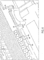
- the ferrule retainer 105 is shown in the unactuated state, and referring to Fig. 6 , the ferrule retainer 105 is shown in the actuated state.
- the connector body 101 of the present invention functions to house and support the ferrule 103 and, in one embodiment, to anchor the connector 100 to a structure such as a circuit board 150 as shown in Fig. 1 , or backplane, as is known in the art.
- the connector body is similar to conventional connector bodies in form factor and materials of construction so the details of which will not be considered herein.
- the connector body 101 has a first latch element 102 which cooperates with the second latch element 106a of the resilient member 106 as discussed in greater detail below.
- a cross-section of one embodiment of the connector 100 is shown.
- this cross-section shows the interaction of the first and second latch elements.
- the first latch element 102 in this particular embodiment, is a recess 501 in the cavity side wall, adjacent the cavity 101a.
- the connector body also defines a lead-in portion 502 having a bevel 502a to facilitate the insertion of the second latch element 106a into the connector body (discussed below).
- the first latch element 102 can be any element known for mechanically engaging with a corresponding latching member or latch element.
- the latch comprises a recess 501 which is configured to receive a protrusion from the second latch element 106a.
- the first latch element is a recess and the second latch element is a protrusion
- the protrusion and the recess can be reversed such that the protrusion is found on the connector body while the resilient defines a recessed for receiving the protrusion.
- Still other latching mechanisms will be obvious to those of skill in the art in light of this disclosure.
- the configuration of the present invention facilitates the use of a connector body 101 having multiple cavities for high-density connector configurations.
- a connector body defines two cavities 101a for receiving ferrule assemblies is shown.
- the connector body of the present invention is suitable for many more cavities in close proximity to one another.
- the connector body could be configured with cavity arrays of 2x2, 3x3, 4x4, 2x4, etc.
- the ferrule retainer 105 is releasably engaged to the connector body using an axially-manipulated actuator 107, there is no need to provide space on the sides of the connectors 100 sufficient for fingers to access the ferrule retainer.
- the connectors are arranged side-by-side in a touching/near-touching proximity. Such a configuration is generally not possible with tool-less ferrule retainers that need to be actuated by squeezing as discussed above.
- the ferrule 103 functions to align and present the terminated fiber ends to a mating device, which may be another connector or an optical device.
- the ferrule may be a single-fiber ferrule or multifiber ferrule.
- the ferrule is a standard/conventional ferrule, such as, for example, an MT ferrule, without any modifications.
- one aspect of the invention is that many of the same components of a standard connector can be used in the connector of the present invention. Accordingly, there is no need to describe the details of the ferrule herein.
- the connector 100 comprises a spring 104 which functions to urge the ferrule 103 forward in the connector body 101 to provide a forward urging force during mating.
- the spring in one embodiment, is a conventional, standard spring. Accordingly, the details of which will not be discussed herein. It should be understood that, although the connector 100 is shown herein with a spring, the spring is not required. For example, in certain applications a spring is not required because the mating connector provides adequate an urging force against the ferrule 103, as is known in the art.
- the ferrule retainer 105 functions to contain the ferrule in the connector body and, in one embodiment, to provide a backstop for the spring which urges the ferrule forward within the connector body cavity as mentioned above.
- the conventional function of ferrule retainers is well-known and will not be discussed in detail herein.
- the ferrule retainer as disclosed herein differs from conventional ferrule retainers in a number of ways, including its ability to be released from the connector body through axially actuation.
- the ferrule retainer 105 comprises three discrete components, a retainer body 110, resilient member 106 and an actuator 107.
- the retainer body 110 functions to receive a back end of the spring 104 and to provide support for the resilient member 106 and the actuator 107.
- the ferrule retainer body comprises a conventional front end 308, which is configured to receive and hold the back end of the spring.
- the retainer body comprises a channel 305 defined along its periphery to receive/accommodate the resilient member 106.
- the ferrule retainer body 100 is disclosed in Fig. 3 with a channel 305, it should that other embodiments are possible.
- the resilient member could be adhered to the retainer body 110, or the retainer body may comprise mechanical interlocks to hold the resilient member 106 in place. Still other embodiments will be obvious to those of skill in the art in light of this disclosure.
- the retainer body 110 comprises a collar 109 or other conduit through which the optical fibers 108 pass.
- the resilient member 106 functions to provide resiliency to urge the second latch element 106a toward the first latch element 102 when the ferrule retainer 105 is engaged with the connector body 101.
- the resilient member 106 comprises distal ends 106b which are free (i.e., not secured to the retainer body), allowing them to move laterally.
- the second latch element 106a is disposed or defined in the resilient member proximate to the distal end 106b such that when the connector is actuated and the distal ends move laterally, the second latch element also moves laterally.
- the second latch element 106a is defined by punching a portion of the resilient member and lifting it to define an outwardly protruding second latch element 106a.
- tabs 302 for securing resilient member 106 to the retainer body 110 are defined by punching a portion of the resilient member and bending/flexing it inwardly to define an inwardly protruding tab.
- the retainer body 110 has a corresponding shoulder 309 against which the tab urges to keep the retainer in place on the retainer body.
- the resilient member 106 in one embodiment, comprises at least one cam surface 301 for cooperating with the actuator 107 such that, when the actuator 107 is pushed over the cam surface 301, it causes the resilient member 106 to deform/bend.
- the resilient member is configured to bend/flex inwardly in the actuated state. It should be understood, however, that the cam surface 301 could be configured in different ways to cooperate with the actuator 107 in different ways. The interaction of the cam surface and the actuator is described in greater detail below.
- the resilient member 106 comprises a material that is capable of bending and/or flexing without deformation.
- the resilient member 106 comprises a metal which is stamped into form. Such an embodiment is particularly well suited for high temperature applications compared to conventional polymeric ferrule retainer configurations which tend to lose their resiliency over time due to high temperature.
- the type of metal that can be used can vary, in one embodiment, the metal is stainless steel. Still other embodiments will be obvious to those of skill in the art in light of this disclosure.
- the actuator 107 functions to cooperate with the resilient member 106 to move the second latch element laterally between an unactuated state and an actuated state.
- the actuator is slidably mounted on the ferrule retainer body 110 such that it slides axially, or in other words, forward and backward (as opposed to lateral motion).
- the actuator is configured such that its axial motions causes the second latch element 106a to move laterally and away from the first latch element 102 such that the latch elements disengage allowing the ferrule retainer 105 to be withdrawn as shown in Fig. 6 .
- the configuration of the actuator 107 can vary according to the application.
- the actuator 107 is sleeve-like and envelopes the rear portion of the ferrule retainer body.
- the actuator 107 is configured to accommodate a user's fingers or a tool with certain contours in its exterior.
- the actuator 107 comprises a pair of finger contours 307 on either side to accommodate a user's fingers.
- the actuator 107 may comprise a notch 306 that receives a simple tool, for example, the end of a straight slot screwdriver.
- a simple tool for example, the end of a straight slot screwdriver.
- Such an embodiment may be preferable in applications in which the connectors are arranged in a high-density configuration. With such an embodiment, the user would insert a common tool like a screwdriver into the slot 306, and then use the screwdriver to push the actuator 107 forward into its actuated state to remove the ferrule retainer.
- the actuator 107 and the resilient member 106 are configured to cooperate such that in the actuated state, the distal ends 106b of the resilient member 106 are moved laterally from their at rest position, thereby facilitating disengagement with the first latch members or elements.
- the actuator is configured to move the distal ends 106b inwardly during actuation.
- the resilient member comprises a protrusion of cam surface 301 which cooperates with the corresponding surface of the actuator 107. Specifically, as the actuator 107 is pushed forward, it rides over the cam surface 301, which causes the distal ends 106b to deflect inwardly as shown in Fig. 6 .
- the actuator and the resilient member could be configured such that the actuator slides inwardly on the inside of the resilient member. In this such configuration, the cam surface would protrude inwardly rather than outwardly. Thus, as the actuator is slid forward, it would contact the inwardly protruding cam surfaces to urge the distal ends 106b outward.
- the actuator is actuated by moving backward (rather than forward) to contact a cam surface on the resilient member. Still other embodiments will be known or obvious to those of skill in the art in light of this disclosure.
- a ferrule 103 terminated with optical fibers 108 is inserted in the cavity 101a of connector body 101.
- the ferrule 103 is pushed forward such that its face is presented at the front surface 101b of a connector as shown in Fig. 5 .
- the face of the ferrule 103 slightly protrudes from the front face 101b of the connector body. This is a typical and well known configuration of a ferrule within a connector body.
- a spring 104 is disposed behind the ferrule and around the optical fibers 108.
- the ferrule retainer 105 is then disposed behind the spring 104 and also around the fibers 108.
- the ferrule retainer 105 is pushed forward within the cavity, thereby compressing the spring 104.
- the distal ends 106b of the resilient member 106 are pushed into the cavity, they deflect inwardly as they contact the bevel surface 502a of the lead-in portion 502 of the connector body. Because the resilient member is flexible, it is able to deflect inwardly as the ferrule retainer is pushed into the cavity.
- the second latch element 106a reaches the first latch element 102, which, in this embodiment is a recess 501, it is able to spring back outwardly such that the second latch element 106a is forced into the recess 501, thereby preventing the ferrule body from being withdrawn without actuation.
- the actuator 107 is pushed forward such that the distal ends 106b move inwardly to a point where the second latch elements 106a are no longer disposed within the recess 501, thereby allowing the ferrule assembly/ferrule retainer to be pulled out of the cavity 101.
Landscapes
- Physics & Mathematics (AREA)
- General Physics & Mathematics (AREA)
- Optics & Photonics (AREA)
- Mechanical Coupling Of Light Guides (AREA)
Abstract
Description
- The present invention relates, generally, to optical connectors, and, more specifically, to an optical connector configured for tool-less removal of a ferrule from the connector.
- A typical optical fiber connector comprises a ferrule disposed in a connector body. The ferrule assembly is often biased forward in the connector body by a spring. The ferrule and spring, if used, are held within the connector body by a ferrule retainer. Of particular interest herein is the ferrule retainer.
- Often there is a need to replace, repair or clean the ferrule within a connector. To this end, the ferrule retainer must be removed to allow the ferrule to be pulled from the connector body. As a matter of convenience, "tool-less" ferrule retainers are often preferred such that the ferrule retainer can be installed in and removed from the connector body without the use of specialized tools.
- Although tool-less ferrule retainers may be convenient, their applicability to high-connector density configurations can be problematic. For example, the applicant recognizes that accessing a ferrule retainer is often difficult when the connectors are closely packed. Specifically, one conventional tool-less approach involves squeezing the ferrule retainer to release it from the connector body. However, often there is little or no space on the side of the connector for the user to insert his/her fingers to squeeze the ferrule retainer. Additionally, the applicant recognizes that conventional tool-less ferrule retainers tend to rely on plastic and other polymeric materials, which tend to degrade or otherwise lose their resiliency over time in high-temperature applications, thereby compromising the connection of the ferrule retainer to the connector body.
- Therefore, the applicant has identified a need for an improved tool-less ferrule retainer that lends itself to high-temperature and high-density connector applications. The present invention fulfills this need among others.
- The solution is provided by a ferrule retainer configuration which facilitates tool-less release from the connector body by moving an actuator axially. Specifically, the applicant has identified that tool-less ferrule retainers that must be squeezed tend to be impractical for high-density connector applications. Accordingly, the applicant discloses herein a configuration in which the ferrule retainer is released through an axial motion actuator. Because the ferrule retainer is releasably engaged to the connector body using an axially-manipulated actuator, there is no need to provide space on the sides of the connectors sufficient for fingers to access the ferrule retainer. Additionally, this configuration facilitates the use of materials, such as metals, in the ferrule retainer which are capable of withstanding high temperatures without significant degradation in their resiliency.
- The invention will now be described by way of example with reference to the accompanying drawings in which:
-
Fig. 1 shows one embodiment of the connector of the present invention in which upper one of the two ferrule assemblies is shown in a disassembled state, while the lower one is shown in an assembled state; -
Fig. 2 shows a perspective view of one embodiment of the ferrule retainer of the present invention; -
Fig. 3 shows an exploded view of the ferrule retainer ofFig. 2 ; -
Fig. 4 shows the connector ofFig. 1 in which both ferrule assemblies are disposed in the connector body in an assembled state; -
Fig. 5 shows a cross-section of the connector ofFig. 4 in an unactuated state; and -
Fig. 6 shows a cross-section of the connector ofFig. 4 in an actuated state. - The invention relates to a ferrule retainer configuration which facilitates tool-less release from the connector body by moving an actuator axially. Specifically, the applicant has identified that tool-less ferrule retainers that must be squeezed tend to be impractical for high-density connector applications. Accordingly, the applicant discloses herein a configuration in which the ferrule retainer is released through an axial motion actuator. Because the ferrule retainer is releasably engaged to the connector body using an axially-manipulated actuator, there is no need to provide space on the sides of the connectors sufficient for fingers to access the ferrule retainer. Additionally, this configuration facilitates the use of materials, such as metals, in the ferrule retainer which are capable of withstanding high temperatures without significant degradation in their resiliency.
- Accordingly, in one embodiment, the invention relates to a ferrule retainer which is releasable from a connector body through axial actuation. In one embodiment, the ferrule retainer retains a ferrule and a spring in a connector body, which defines at least one cavity and at least one first latch element adjacent the cavity, the ferrule retainer comprising: (a) a retainer body configured for insertion into the cavity; (b) a resilient member attached to the retainer body, the resilient member having a relaxed state, and comprising at least one second latch element configured for releasably engaging the at least one first latch element; and (c) an actuator slidably mounted for forward and backward movement on the retainer body, the actuator having an actuated and an unactuated state, in the actuated state, the actuator bends the resilient member, thereby causing the at least one second latch element to move laterally relative to its position when the resilient member is in its relaxed state, and, in the unactuated state, the actuator does not significantly bend/flex the resilient member.
- In another embodiment, the invention relates to connector having a tool-less ferrule retainer. In one embodiment, the connector has a front and rear origination and comprises: (a) a connector body having defining a cavity to receive a ferrule and at least one first latch element; (b) a ferrule disposed in the cavity; (c) a spring disposed behind the ferrule; and (d) a ferrule retainer for retaining the ferrule and the spring in the connector body, the ferrule retainer comprising at least: (i) a retainer body configured for insertion into the cavity; (ii) a resilient member attached to the retainer body, the resilient member having a relaxed state, and comprising at least one second latch element configured for releasably engaging the at least one first latch element; and (iii) an actuator slidably mounted for forward and backward movement on the retainer body, the actuator having an actuated and an unactuated state, in the actuated state, the actuator bends the resilient member, thereby causing the at least one second latch element to move laterally relative to its position when the resilient member is in its relaxed state, and in the unactuated state, the actuator does not significantly bend/flex the resilient member.
- Referring to
Figs. 1 through 5 , one embodiment of theconnector 100 of the invention is shown. Theconnector 100 has a front and rear origination, and comprises aconnector body 101 defining at least onecavity 101a to receive aferrule 103, and having at least one first latch orlatching element 102 adjacent the cavity. In the assembled state, theferrule 103 disposed in thecavity 101a as shown in theFig. 5 . Aspring 104 is disposed behind or adjacent the ferrule or to the rear of the ferrule in relation to the origination of the connector. Aferrule retainer 105 is used for retaining the ferrule and the spring in the connector body. Referring toFig. 3 , the ferrule retainer comprises at least aretainer body 110 configured for insertion into the cavity, and aresilient member 106 attached to the retainer body. The resilient member has a relaxed state, and comprises at least one second latch orlatching element 106a configured for releasably engaging the at least onefirst latch element 102. The ferrule retainer also comprises anactuator 107 slidably mounted for forward and backward movement on the retainer body or for movement in a first direction or an opposite second direction on the retainer body. The ferrule retainer has an actuated and an unactuated state. In the actuated state, the actuator bends the resilient member, thereby causing the at least one second latch element to move laterally relative to its position when the resilient member is in its relaxed state, and, in the unactuated state, the actuator does not significantly or substantially bend/flex the resilient member. Referring toFig. 5 , theferrule retainer 105 is shown in the unactuated state, and referring toFig. 6 , theferrule retainer 105 is shown in the actuated state. - These elements are described in greater detail below and in connection with selected alternative embodiments.
- The
connector body 101 of the present invention functions to house and support theferrule 103 and, in one embodiment, to anchor theconnector 100 to a structure such as acircuit board 150 as shown inFig. 1 , or backplane, as is known in the art. The connector body is similar to conventional connector bodies in form factor and materials of construction so the details of which will not be considered herein. - In one embodiment, the
connector body 101 has afirst latch element 102 which cooperates with thesecond latch element 106a of theresilient member 106 as discussed in greater detail below. Specifically, referring toFig. 5 , a cross-section of one embodiment of theconnector 100 is shown. In particular, this cross-section shows the interaction of the first and second latch elements. Thefirst latch element 102, in this particular embodiment, is arecess 501 in the cavity side wall, adjacent thecavity 101a. In this particular embodiment, the connector body also defines a lead-inportion 502 having abevel 502a to facilitate the insertion of thesecond latch element 106a into the connector body (discussed below). - The
first latch element 102 can be any element known for mechanically engaging with a corresponding latching member or latch element. For example, as shown, the latch comprises arecess 501 which is configured to receive a protrusion from thesecond latch element 106a. Although in this embodiment, the first latch element is a recess and the second latch element is a protrusion, it should be understood that other embodiments are possible. For example, the protrusion and the recess can be reversed such that the protrusion is found on the connector body while the resilient defines a recessed for receiving the protrusion. Still other latching mechanisms will be obvious to those of skill in the art in light of this disclosure. - The configuration of the present invention facilitates the use of a
connector body 101 having multiple cavities for high-density connector configurations. For example, referring toFig. 1 , a connector body defines twocavities 101a for receiving ferrule assemblies is shown. However, it should be understood that the connector body of the present invention is suitable for many more cavities in close proximity to one another. For example, the connector body could be configured with cavity arrays of 2x2, 3x3, 4x4, 2x4, etc. Furthermore, because theferrule retainer 105 is releasably engaged to the connector body using an axially-manipulatedactuator 107, there is no need to provide space on the sides of theconnectors 100 sufficient for fingers to access the ferrule retainer. Indeed, in one embodiment, the connectors are arranged side-by-side in a touching/near-touching proximity. Such a configuration is generally not possible with tool-less ferrule retainers that need to be actuated by squeezing as discussed above. - Still other embodiments of the connector body will be obvious of skill in the art in light of this disclosure.
- The
ferrule 103 functions to align and present the terminated fiber ends to a mating device, which may be another connector or an optical device. The ferrule may be a single-fiber ferrule or multifiber ferrule. In one embodiment, the ferrule is a standard/conventional ferrule, such as, for example, an MT ferrule, without any modifications. Indeed, one aspect of the invention is that many of the same components of a standard connector can be used in the connector of the present invention. Accordingly, there is no need to describe the details of the ferrule herein. - In one embodiment, the
connector 100 comprises aspring 104 which functions to urge theferrule 103 forward in theconnector body 101 to provide a forward urging force during mating. The spring, in one embodiment, is a conventional, standard spring. Accordingly, the details of which will not be discussed herein. It should be understood that, although theconnector 100 is shown herein with a spring, the spring is not required. For example, in certain applications a spring is not required because the mating connector provides adequate an urging force against theferrule 103, as is known in the art. - The
ferrule retainer 105 functions to contain the ferrule in the connector body and, in one embodiment, to provide a backstop for the spring which urges the ferrule forward within the connector body cavity as mentioned above. The conventional function of ferrule retainers is well-known and will not be discussed in detail herein. However, the ferrule retainer as disclosed herein differs from conventional ferrule retainers in a number of ways, including its ability to be released from the connector body through axially actuation. - Referring to
Figs. 2 and3 , one embodiment of theferrule retainer 105 is shown. In this embodiment, the ferrule retainer comprises three discrete components, aretainer body 110,resilient member 106 and anactuator 107. - In one embodiment, the
retainer body 110 functions to receive a back end of thespring 104 and to provide support for theresilient member 106 and theactuator 107. In one embodiment, the ferrule retainer body comprises a conventionalfront end 308, which is configured to receive and hold the back end of the spring. - In one embodiment, the retainer body comprises a
channel 305 defined along its periphery to receive/accommodate theresilient member 106. Although theferrule retainer body 100 is disclosed inFig. 3 with achannel 305, it should that other embodiments are possible. For example, the resilient member could be adhered to theretainer body 110, or the retainer body may comprise mechanical interlocks to hold theresilient member 106 in place. Still other embodiments will be obvious to those of skill in the art in light of this disclosure. - In one embodiment, the
retainer body 110 comprises acollar 109 or other conduit through which theoptical fibers 108 pass. - The
resilient member 106 functions to provide resiliency to urge thesecond latch element 106a toward thefirst latch element 102 when theferrule retainer 105 is engaged with theconnector body 101. To this end, in one embodiment, theresilient member 106 comprisesdistal ends 106b which are free (i.e., not secured to the retainer body), allowing them to move laterally. Thesecond latch element 106a is disposed or defined in the resilient member proximate to thedistal end 106b such that when the connector is actuated and the distal ends move laterally, the second latch element also moves laterally. In the embodiment shown inFig. 3 , thesecond latch element 106a is defined by punching a portion of the resilient member and lifting it to define an outwardly protrudingsecond latch element 106a. - Likewise, in one embodiment,
tabs 302 for securingresilient member 106 to theretainer body 110 are defined by punching a portion of the resilient member and bending/flexing it inwardly to define an inwardly protruding tab. Theretainer body 110 has acorresponding shoulder 309 against which the tab urges to keep the retainer in place on the retainer body. - The
resilient member 106, in one embodiment, comprises at least onecam surface 301 for cooperating with theactuator 107 such that, when theactuator 107 is pushed over thecam surface 301, it causes theresilient member 106 to deform/bend. In this particular embodiment, the resilient member is configured to bend/flex inwardly in the actuated state. It should be understood, however, that thecam surface 301 could be configured in different ways to cooperate with theactuator 107 in different ways. The interaction of the cam surface and the actuator is described in greater detail below. - The
resilient member 106 comprises a material that is capable of bending and/or flexing without deformation. In one embodiment, theresilient member 106 comprises a metal which is stamped into form. Such an embodiment is particularly well suited for high temperature applications compared to conventional polymeric ferrule retainer configurations which tend to lose their resiliency over time due to high temperature. The type of metal that can be used can vary, in one embodiment, the metal is stainless steel. Still other embodiments will be obvious to those of skill in the art in light of this disclosure. - The actuator 107 functions to cooperate with the
resilient member 106 to move the second latch element laterally between an unactuated state and an actuated state. In one embodiment, the actuator is slidably mounted on theferrule retainer body 110 such that it slides axially, or in other words, forward and backward (as opposed to lateral motion). In other words, the actuator is configured such that its axial motions causes thesecond latch element 106a to move laterally and away from thefirst latch element 102 such that the latch elements disengage allowing theferrule retainer 105 to be withdrawn as shown inFig. 6 . The configuration of theactuator 107 can vary according to the application. In one embodiment, theactuator 107 is sleeve-like and envelopes the rear portion of the ferrule retainer body. In one embodiment, theactuator 107 is configured to accommodate a user's fingers or a tool with certain contours in its exterior. For example, in embodiment ofFig. 3 , theactuator 107 comprises a pair offinger contours 307 on either side to accommodate a user's fingers. Alternatively, or in addition to thefinger contours 307, theactuator 107 may comprise anotch 306 that receives a simple tool, for example, the end of a straight slot screwdriver. Such an embodiment may be preferable in applications in which the connectors are arranged in a high-density configuration. With such an embodiment, the user would insert a common tool like a screwdriver into theslot 306, and then use the screwdriver to push theactuator 107 forward into its actuated state to remove the ferrule retainer. - The
actuator 107 and theresilient member 106 are configured to cooperate such that in the actuated state, the distal ends 106b of theresilient member 106 are moved laterally from their at rest position, thereby facilitating disengagement with the first latch members or elements. This could be accomplished in different ways. For example, in the embodiment shown inFig. 3 , the actuator is configured to move the distal ends 106b inwardly during actuation. In this embodiment, the resilient member comprises a protrusion ofcam surface 301 which cooperates with the corresponding surface of theactuator 107. Specifically, as theactuator 107 is pushed forward, it rides over thecam surface 301, which causes the distal ends 106b to deflect inwardly as shown inFig. 6 . Because thesecond latch elements 106a are located proximately to the distal ends 106b, when the distal ends 106b move inwardly, so do the second latch elements thereby facilitating disengagement with thefirst latch element 102. Alternatively, the actuator and the resilient member could be configured such that the actuator slides inwardly on the inside of the resilient member. In this such configuration, the cam surface would protrude inwardly rather than outwardly. Thus, as the actuator is slid forward, it would contact the inwardly protruding cam surfaces to urge the distal ends 106b outward. In yet another embodiment, the actuator is actuated by moving backward (rather than forward) to contact a cam surface on the resilient member. Still other embodiments will be known or obvious to those of skill in the art in light of this disclosure. - The installation of the ferrule retaining body is straightforward. Referring to
Figs. 1 and5 , the installation of a ferrule in the connector body will be discussed. Aferrule 103 terminated withoptical fibers 108 is inserted in thecavity 101a ofconnector body 101. Theferrule 103 is pushed forward such that its face is presented at thefront surface 101b of a connector as shown inFig. 5 . In one embodiment, the face of theferrule 103 slightly protrudes from thefront face 101b of the connector body. This is a typical and well known configuration of a ferrule within a connector body. Next, aspring 104 is disposed behind the ferrule and around theoptical fibers 108. Theferrule retainer 105 is then disposed behind thespring 104 and also around thefibers 108. Theferrule retainer 105 is pushed forward within the cavity, thereby compressing thespring 104. As the distal ends 106b of theresilient member 106 are pushed into the cavity, they deflect inwardly as they contact thebevel surface 502a of the lead-inportion 502 of the connector body. Because the resilient member is flexible, it is able to deflect inwardly as the ferrule retainer is pushed into the cavity. Once thesecond latch element 106a reaches thefirst latch element 102, which, in this embodiment is arecess 501, it is able to spring back outwardly such that thesecond latch element 106a is forced into therecess 501, thereby preventing the ferrule body from being withdrawn without actuation. - During actuation, as discussed above, the
actuator 107 is pushed forward such that the distal ends 106b move inwardly to a point where thesecond latch elements 106a are no longer disposed within therecess 501, thereby allowing the ferrule assembly/ferrule retainer to be pulled out of thecavity 101.
Claims (13)
- A ferrule retainer (105) for retaining a ferrule (103) and a spring (104) in a connector body (101), said connector body (101) defining at least one cavity (101a) and at least one first latch element (102) adjacent said cavity, said ferrule retainer (105) comprising
a retainer body (110) configured for insertion into said cavity (101);
a resilient member (106) attached to said retainer body (110), said resilient member (106) having a relaxed state, and comprising at least one second latch element (106a) configured for releasably engaging said at least one first latch element (102); and
an actuator (107) slidably mounted for movement in a first direction or an opposite second direction on said retainer body (110), said actuator (107) having an actuated and an unactuated state, in said actuated state, said actuator (107) bends said resilient member (106), thereby causing said at least one second latch element (106a) to move laterally relative to its position when said resilient member (106) is in its relaxed state, and, in said unactuated state, said actuator (107) does not substantially bend/flex said resilient member (106). - The ferrule retainer of claim 1, wherein in said unactuated state, said resilient member (106) is in its relaxed state.
- The ferrule retainer of claim 1 or 2, wherein said resilient member (106) comprises at least one distal end (106b) and said at least one second latch element (106a) is disposed proximate to said distal end.
- The ferrule retainer of claim 1, 2 or 3, wherein said resilient member (106) comprises two distal ends (106b), and said at least one second latch element (106a) comprises a second latch element located proximate to each of said two distal ends (106b).
- The ferrule retainer of any preceding claim, wherein said resilient member (106) comprises at least one cam surface (301), said actuator (107) and said at least one cam surface (301) configured such that as said actuator moves axially to its actuated state, the actuator slides on said cam surface (301) causing said at least one distal end (106b) to move laterally.
- The ferrule retainer of claim 5, wherein said cam surface (301) comprises an outwardly protruding surface such that said at least one distal end (106b) moves laterally inwardly.
- The ferrule retainer of any preceding claim, wherein said resilient member (106) comprises metal.
- The ferrule retainer of any preceding claim, wherein, in said actuated state, said actuator (107) bends said resilient member (106) such that said at least one second latch element (106a) moves laterally inward relative to its position when said resilient member (106) is in its relaxed state.
- The ferrule retainer of any preceding claim, wherein said resilient member (106) is a discrete component.
- A connector (100) having a front and rear origination and comprising:a connector body (101) defining at least one cavity (101a) to receive a ferrule (103) and at least one first latch element (102);a ferrule (103) disposed in said cavity (101a);a spring (104) disposed behind said ferrule (103); anda ferrule retainer (105) of any preceding claim.
- The connector of claim 10, wherein said first latch element (102) is a recess (501) and said second latch element (106a) is a latch.
- The connector of claim 11, wherein in said actuated state, said actuator (107) bends said resilient member (106) inwardly such that said latch does not extend into said recess (501), and, in said unactuated state, said release does not substantially interfere with said resilient latch, allowing said resilient latch to urge against said connector body (101) such that said latch extends into said recess (501).
- The connector of claim 10, 11 or 12, wherein said connector body (101) defines multiple cavities.
Applications Claiming Priority (1)
| Application Number | Priority Date | Filing Date | Title |
|---|---|---|---|
| US15/690,598 US10168488B1 (en) | 2017-08-30 | 2017-08-30 | Tool-less ferrule retainer |
Publications (2)
| Publication Number | Publication Date |
|---|---|
| EP3451034A1 true EP3451034A1 (en) | 2019-03-06 |
| EP3451034B1 EP3451034B1 (en) | 2023-03-22 |
Family
ID=63371534
Family Applications (1)
| Application Number | Title | Priority Date | Filing Date |
|---|---|---|---|
| EP18190398.0A Active EP3451034B1 (en) | 2017-08-30 | 2018-08-23 | Tool-less ferrule retainer |
Country Status (2)
| Country | Link |
|---|---|
| US (1) | US10168488B1 (en) |
| EP (1) | EP3451034B1 (en) |
Families Citing this family (4)
| Publication number | Priority date | Publication date | Assignee | Title |
|---|---|---|---|---|
| DE102019103853A1 (en) * | 2019-02-15 | 2020-08-20 | Harting Electric Gmbh & Co. Kg | Connector with locking and unlocking function |
| WO2022120756A1 (en) * | 2020-12-10 | 2022-06-16 | 深南电路股份有限公司 | Connection assembly, cable plug and cable assembly |
| JPWO2023032712A1 (en) * | 2021-08-30 | 2023-03-09 | ||
| TWI835343B (en) * | 2022-07-13 | 2024-03-11 | 神基科技股份有限公司 | Rugged plug and unplugging method thereof |
Citations (2)
| Publication number | Priority date | Publication date | Assignee | Title |
|---|---|---|---|---|
| US5634809A (en) * | 1995-08-21 | 1997-06-03 | Honda Tsushin Kogyo Kabushiki Kaisha Tsushin Kogyo Co. Ltd. | Connector with lock mechanism |
| US6513989B1 (en) * | 1997-06-24 | 2003-02-04 | Tyco Electronics Logistics Ag | Ferrule container for holding a multiple optical fiber disposed in a ferrule, and a connector for connecting multiple optical fibers |
Family Cites Families (7)
| Publication number | Priority date | Publication date | Assignee | Title |
|---|---|---|---|---|
| US5967809A (en) * | 1996-09-23 | 1999-10-19 | General Motors Corporation | Electrical connector |
| FR2808862B1 (en) * | 2000-05-10 | 2002-07-19 | Legris Sa | DEVICE FOR CONNECTING A TIP TO AN ORGAN |
| US6601933B1 (en) * | 2002-06-21 | 2003-08-05 | General Devices Co., Inc. | Telescoping slide with quick-mount system |
| JP6156904B2 (en) * | 2012-09-14 | 2017-07-05 | タイコエレクトロニクスジャパン合同会社 | connector |
| JP2015125217A (en) * | 2013-12-26 | 2015-07-06 | 住友電気工業株式会社 | Optical coupling mechanism and optical transceiver |
| US9557497B2 (en) * | 2014-10-20 | 2017-01-31 | Archtech Electronics Corp. | SC optical fiber connector |
| JP6588718B2 (en) * | 2015-03-30 | 2019-10-09 | 株式会社フジクラ | Optical connector parts |
-
2017
- 2017-08-30 US US15/690,598 patent/US10168488B1/en active Active
-
2018
- 2018-08-23 EP EP18190398.0A patent/EP3451034B1/en active Active
Patent Citations (2)
| Publication number | Priority date | Publication date | Assignee | Title |
|---|---|---|---|---|
| US5634809A (en) * | 1995-08-21 | 1997-06-03 | Honda Tsushin Kogyo Kabushiki Kaisha Tsushin Kogyo Co. Ltd. | Connector with lock mechanism |
| US6513989B1 (en) * | 1997-06-24 | 2003-02-04 | Tyco Electronics Logistics Ag | Ferrule container for holding a multiple optical fiber disposed in a ferrule, and a connector for connecting multiple optical fibers |
Also Published As
| Publication number | Publication date |
|---|---|
| EP3451034B1 (en) | 2023-03-22 |
| US10168488B1 (en) | 2019-01-01 |
Similar Documents
| Publication | Publication Date | Title |
|---|---|---|
| US10120138B2 (en) | Connector with trigger locking feature, and cable assemblies and methods including the same | |
| US20250224573A1 (en) | Crimp body for mini duplex connector with push-pull polarity mechanism and carrier | |
| US11181701B2 (en) | Optical connectors with reversible polarity and method of use | |
| EP3451034B1 (en) | Tool-less ferrule retainer | |
| KR102239204B1 (en) | Narrow width adapters and connectors with modular latching arms | |
| US7297013B2 (en) | Push-pull plugs and tools | |
| US7204016B2 (en) | Ferrule assembly and methods therefor | |
| US6776645B2 (en) | Latch and release system for a connector | |
| US9804340B1 (en) | Optical fiber connector capable of switching connection polarity | |
| US10416394B2 (en) | Fiber optic receptacle with integrated device therein | |
| EP1073923A1 (en) | Plug housing with attached cantilever latch for a fiber optic connector | |
| EP0685750A1 (en) | Connector for connecting an optical fiber cable | |
| CN113156586B (en) | Optical connector with reversible polarity | |
| JP2021071525A (en) | Optical connector removal tool |
Legal Events
| Date | Code | Title | Description |
|---|---|---|---|
| PUAI | Public reference made under article 153(3) epc to a published international application that has entered the european phase |
Free format text: ORIGINAL CODE: 0009012 |
|
| STAA | Information on the status of an ep patent application or granted ep patent |
Free format text: STATUS: THE APPLICATION HAS BEEN PUBLISHED |
|
| AK | Designated contracting states |
Kind code of ref document: A1 Designated state(s): AL AT BE BG CH CY CZ DE DK EE ES FI FR GB GR HR HU IE IS IT LI LT LU LV MC MK MT NL NO PL PT RO RS SE SI SK SM TR |
|
| AX | Request for extension of the european patent |
Extension state: BA ME |
|
| STAA | Information on the status of an ep patent application or granted ep patent |
Free format text: STATUS: REQUEST FOR EXAMINATION WAS MADE |
|
| 17P | Request for examination filed |
Effective date: 20190904 |
|
| RBV | Designated contracting states (corrected) |
Designated state(s): AL AT BE BG CH CY CZ DE DK EE ES FI FR GB GR HR HU IE IS IT LI LT LU LV MC MK MT NL NO PL PT RO RS SE SI SK SM TR |
|
| STAA | Information on the status of an ep patent application or granted ep patent |
Free format text: STATUS: EXAMINATION IS IN PROGRESS |
|
| 17Q | First examination report despatched |
Effective date: 20210616 |
|
| GRAP | Despatch of communication of intention to grant a patent |
Free format text: ORIGINAL CODE: EPIDOSNIGR1 |
|
| STAA | Information on the status of an ep patent application or granted ep patent |
Free format text: STATUS: GRANT OF PATENT IS INTENDED |
|
| INTG | Intention to grant announced |
Effective date: 20221117 |
|
| RIN1 | Information on inventor provided before grant (corrected) |
Inventor name: FABIAN, DAVID JAMES |
|
| GRAS | Grant fee paid |
Free format text: ORIGINAL CODE: EPIDOSNIGR3 |
|
| GRAA | (expected) grant |
Free format text: ORIGINAL CODE: 0009210 |
|
| STAA | Information on the status of an ep patent application or granted ep patent |
Free format text: STATUS: THE PATENT HAS BEEN GRANTED |
|
| AK | Designated contracting states |
Kind code of ref document: B1 Designated state(s): AL AT BE BG CH CY CZ DE DK EE ES FI FR GB GR HR HU IE IS IT LI LT LU LV MC MK MT NL NO PL PT RO RS SE SI SK SM TR |
|
| REG | Reference to a national code |
Ref country code: GB Ref legal event code: FG4D |
|
| REG | Reference to a national code |
Ref country code: CH Ref legal event code: EP |
|
| REG | Reference to a national code |
Ref country code: DE Ref legal event code: R096 Ref document number: 602018047423 Country of ref document: DE |
|
| REG | Reference to a national code |
Ref country code: IE Ref legal event code: FG4D |
|
| REG | Reference to a national code |
Ref country code: AT Ref legal event code: REF Ref document number: 1555661 Country of ref document: AT Kind code of ref document: T Effective date: 20230415 |
|
| REG | Reference to a national code |
Ref country code: LT Ref legal event code: MG9D |
|
| REG | Reference to a national code |
Ref country code: NL Ref legal event code: MP Effective date: 20230322 |
|
| PG25 | Lapsed in a contracting state [announced via postgrant information from national office to epo] |
Ref country code: RS Free format text: LAPSE BECAUSE OF FAILURE TO SUBMIT A TRANSLATION OF THE DESCRIPTION OR TO PAY THE FEE WITHIN THE PRESCRIBED TIME-LIMIT Effective date: 20230322 Ref country code: NO Free format text: LAPSE BECAUSE OF FAILURE TO SUBMIT A TRANSLATION OF THE DESCRIPTION OR TO PAY THE FEE WITHIN THE PRESCRIBED TIME-LIMIT Effective date: 20230622 Ref country code: LV Free format text: LAPSE BECAUSE OF FAILURE TO SUBMIT A TRANSLATION OF THE DESCRIPTION OR TO PAY THE FEE WITHIN THE PRESCRIBED TIME-LIMIT Effective date: 20230322 Ref country code: LT Free format text: LAPSE BECAUSE OF FAILURE TO SUBMIT A TRANSLATION OF THE DESCRIPTION OR TO PAY THE FEE WITHIN THE PRESCRIBED TIME-LIMIT Effective date: 20230322 Ref country code: HR Free format text: LAPSE BECAUSE OF FAILURE TO SUBMIT A TRANSLATION OF THE DESCRIPTION OR TO PAY THE FEE WITHIN THE PRESCRIBED TIME-LIMIT Effective date: 20230322 |
|
| REG | Reference to a national code |
Ref country code: AT Ref legal event code: MK05 Ref document number: 1555661 Country of ref document: AT Kind code of ref document: T Effective date: 20230322 |
|
| PG25 | Lapsed in a contracting state [announced via postgrant information from national office to epo] |
Ref country code: SE Free format text: LAPSE BECAUSE OF FAILURE TO SUBMIT A TRANSLATION OF THE DESCRIPTION OR TO PAY THE FEE WITHIN THE PRESCRIBED TIME-LIMIT Effective date: 20230322 Ref country code: NL Free format text: LAPSE BECAUSE OF FAILURE TO SUBMIT A TRANSLATION OF THE DESCRIPTION OR TO PAY THE FEE WITHIN THE PRESCRIBED TIME-LIMIT Effective date: 20230322 Ref country code: GR Free format text: LAPSE BECAUSE OF FAILURE TO SUBMIT A TRANSLATION OF THE DESCRIPTION OR TO PAY THE FEE WITHIN THE PRESCRIBED TIME-LIMIT Effective date: 20230623 Ref country code: FI Free format text: LAPSE BECAUSE OF FAILURE TO SUBMIT A TRANSLATION OF THE DESCRIPTION OR TO PAY THE FEE WITHIN THE PRESCRIBED TIME-LIMIT Effective date: 20230322 |
|
| RAP2 | Party data changed (patent owner data changed or rights of a patent transferred) |
Owner name: TE CONNECTIVITY SOLUTIONS GMBH |
|
| PG25 | Lapsed in a contracting state [announced via postgrant information from national office to epo] |
Ref country code: SM Free format text: LAPSE BECAUSE OF FAILURE TO SUBMIT A TRANSLATION OF THE DESCRIPTION OR TO PAY THE FEE WITHIN THE PRESCRIBED TIME-LIMIT Effective date: 20230322 Ref country code: RO Free format text: LAPSE BECAUSE OF FAILURE TO SUBMIT A TRANSLATION OF THE DESCRIPTION OR TO PAY THE FEE WITHIN THE PRESCRIBED TIME-LIMIT Effective date: 20230322 Ref country code: PT Free format text: LAPSE BECAUSE OF FAILURE TO SUBMIT A TRANSLATION OF THE DESCRIPTION OR TO PAY THE FEE WITHIN THE PRESCRIBED TIME-LIMIT Effective date: 20230724 Ref country code: ES Free format text: LAPSE BECAUSE OF FAILURE TO SUBMIT A TRANSLATION OF THE DESCRIPTION OR TO PAY THE FEE WITHIN THE PRESCRIBED TIME-LIMIT Effective date: 20230322 Ref country code: EE Free format text: LAPSE BECAUSE OF FAILURE TO SUBMIT A TRANSLATION OF THE DESCRIPTION OR TO PAY THE FEE WITHIN THE PRESCRIBED TIME-LIMIT Effective date: 20230322 Ref country code: AT Free format text: LAPSE BECAUSE OF FAILURE TO SUBMIT A TRANSLATION OF THE DESCRIPTION OR TO PAY THE FEE WITHIN THE PRESCRIBED TIME-LIMIT Effective date: 20230322 |
|
| PG25 | Lapsed in a contracting state [announced via postgrant information from national office to epo] |
Ref country code: SK Free format text: LAPSE BECAUSE OF FAILURE TO SUBMIT A TRANSLATION OF THE DESCRIPTION OR TO PAY THE FEE WITHIN THE PRESCRIBED TIME-LIMIT Effective date: 20230322 Ref country code: PL Free format text: LAPSE BECAUSE OF FAILURE TO SUBMIT A TRANSLATION OF THE DESCRIPTION OR TO PAY THE FEE WITHIN THE PRESCRIBED TIME-LIMIT Effective date: 20230322 Ref country code: IS Free format text: LAPSE BECAUSE OF FAILURE TO SUBMIT A TRANSLATION OF THE DESCRIPTION OR TO PAY THE FEE WITHIN THE PRESCRIBED TIME-LIMIT Effective date: 20230722 |
|
| REG | Reference to a national code |
Ref country code: DE Ref legal event code: R097 Ref document number: 602018047423 Country of ref document: DE |
|
| PLBE | No opposition filed within time limit |
Free format text: ORIGINAL CODE: 0009261 |
|
| STAA | Information on the status of an ep patent application or granted ep patent |
Free format text: STATUS: NO OPPOSITION FILED WITHIN TIME LIMIT |
|
| PG25 | Lapsed in a contracting state [announced via postgrant information from national office to epo] |
Ref country code: SI Free format text: LAPSE BECAUSE OF FAILURE TO SUBMIT A TRANSLATION OF THE DESCRIPTION OR TO PAY THE FEE WITHIN THE PRESCRIBED TIME-LIMIT Effective date: 20230322 Ref country code: DK Free format text: LAPSE BECAUSE OF FAILURE TO SUBMIT A TRANSLATION OF THE DESCRIPTION OR TO PAY THE FEE WITHIN THE PRESCRIBED TIME-LIMIT Effective date: 20230322 Ref country code: CZ Free format text: LAPSE BECAUSE OF FAILURE TO SUBMIT A TRANSLATION OF THE DESCRIPTION OR TO PAY THE FEE WITHIN THE PRESCRIBED TIME-LIMIT Effective date: 20230322 |
|
| 26N | No opposition filed |
Effective date: 20240102 |
|
| PG25 | Lapsed in a contracting state [announced via postgrant information from national office to epo] |
Ref country code: MC Free format text: LAPSE BECAUSE OF FAILURE TO SUBMIT A TRANSLATION OF THE DESCRIPTION OR TO PAY THE FEE WITHIN THE PRESCRIBED TIME-LIMIT Effective date: 20230322 |
|
| REG | Reference to a national code |
Ref country code: CH Ref legal event code: PL |
|
| PG25 | Lapsed in a contracting state [announced via postgrant information from national office to epo] |
Ref country code: MC Free format text: LAPSE BECAUSE OF FAILURE TO SUBMIT A TRANSLATION OF THE DESCRIPTION OR TO PAY THE FEE WITHIN THE PRESCRIBED TIME-LIMIT Effective date: 20230322 |
|
| PG25 | Lapsed in a contracting state [announced via postgrant information from national office to epo] |
Ref country code: LU Free format text: LAPSE BECAUSE OF NON-PAYMENT OF DUE FEES Effective date: 20230823 |
|
| PG25 | Lapsed in a contracting state [announced via postgrant information from national office to epo] |
Ref country code: LU Free format text: LAPSE BECAUSE OF NON-PAYMENT OF DUE FEES Effective date: 20230823 Ref country code: CH Free format text: LAPSE BECAUSE OF NON-PAYMENT OF DUE FEES Effective date: 20230831 |
|
| REG | Reference to a national code |
Ref country code: BE Ref legal event code: MM Effective date: 20230831 |
|
| REG | Reference to a national code |
Ref country code: IE Ref legal event code: MM4A |
|
| PG25 | Lapsed in a contracting state [announced via postgrant information from national office to epo] |
Ref country code: IT Free format text: LAPSE BECAUSE OF FAILURE TO SUBMIT A TRANSLATION OF THE DESCRIPTION OR TO PAY THE FEE WITHIN THE PRESCRIBED TIME-LIMIT Effective date: 20230322 |
|
| PG25 | Lapsed in a contracting state [announced via postgrant information from national office to epo] |
Ref country code: IE Free format text: LAPSE BECAUSE OF NON-PAYMENT OF DUE FEES Effective date: 20230823 |
|
| PG25 | Lapsed in a contracting state [announced via postgrant information from national office to epo] |
Ref country code: IE Free format text: LAPSE BECAUSE OF NON-PAYMENT OF DUE FEES Effective date: 20230823 |
|
| PG25 | Lapsed in a contracting state [announced via postgrant information from national office to epo] |
Ref country code: BE Free format text: LAPSE BECAUSE OF NON-PAYMENT OF DUE FEES Effective date: 20230831 |
|
| PG25 | Lapsed in a contracting state [announced via postgrant information from national office to epo] |
Ref country code: BG Free format text: LAPSE BECAUSE OF FAILURE TO SUBMIT A TRANSLATION OF THE DESCRIPTION OR TO PAY THE FEE WITHIN THE PRESCRIBED TIME-LIMIT Effective date: 20230322 |
|
| PG25 | Lapsed in a contracting state [announced via postgrant information from national office to epo] |
Ref country code: BG Free format text: LAPSE BECAUSE OF FAILURE TO SUBMIT A TRANSLATION OF THE DESCRIPTION OR TO PAY THE FEE WITHIN THE PRESCRIBED TIME-LIMIT Effective date: 20230322 |
|
| PG25 | Lapsed in a contracting state [announced via postgrant information from national office to epo] |
Ref country code: CY Free format text: LAPSE BECAUSE OF FAILURE TO SUBMIT A TRANSLATION OF THE DESCRIPTION OR TO PAY THE FEE WITHIN THE PRESCRIBED TIME-LIMIT; INVALID AB INITIO Effective date: 20180823 |
|
| PG25 | Lapsed in a contracting state [announced via postgrant information from national office to epo] |
Ref country code: HU Free format text: LAPSE BECAUSE OF FAILURE TO SUBMIT A TRANSLATION OF THE DESCRIPTION OR TO PAY THE FEE WITHIN THE PRESCRIBED TIME-LIMIT; INVALID AB INITIO Effective date: 20180823 |
|
| PGFP | Annual fee paid to national office [announced via postgrant information from national office to epo] |
Ref country code: DE Payment date: 20250702 Year of fee payment: 8 |
|
| PGFP | Annual fee paid to national office [announced via postgrant information from national office to epo] |
Ref country code: GB Payment date: 20250703 Year of fee payment: 8 |
|
| PGFP | Annual fee paid to national office [announced via postgrant information from national office to epo] |
Ref country code: FR Payment date: 20250703 Year of fee payment: 8 |
|
| PG25 | Lapsed in a contracting state [announced via postgrant information from national office to epo] |
Ref country code: TR Free format text: LAPSE BECAUSE OF FAILURE TO SUBMIT A TRANSLATION OF THE DESCRIPTION OR TO PAY THE FEE WITHIN THE PRESCRIBED TIME-LIMIT Effective date: 20230322 |