EP3451008A1 - Magnetic field map determination in a mr system - Google Patents
Magnetic field map determination in a mr system Download PDFInfo
- Publication number
- EP3451008A1 EP3451008A1 EP17188159.2A EP17188159A EP3451008A1 EP 3451008 A1 EP3451008 A1 EP 3451008A1 EP 17188159 A EP17188159 A EP 17188159A EP 3451008 A1 EP3451008 A1 EP 3451008A1
- Authority
- EP
- European Patent Office
- Prior art keywords
- field map
- patient support
- magnetic field
- shim
- stationary
- Prior art date
- Legal status (The legal status is an assumption and is not a legal conclusion. Google has not performed a legal analysis and makes no representation as to the accuracy of the status listed.)
- Granted
Links
Images



Classifications
-
- G—PHYSICS
- G01—MEASURING; TESTING
- G01R—MEASURING ELECTRIC VARIABLES; MEASURING MAGNETIC VARIABLES
- G01R33/00—Arrangements or instruments for measuring magnetic variables
- G01R33/20—Arrangements or instruments for measuring magnetic variables involving magnetic resonance
- G01R33/44—Arrangements or instruments for measuring magnetic variables involving magnetic resonance using nuclear magnetic resonance [NMR]
- G01R33/48—NMR imaging systems
- G01R33/54—Signal processing systems, e.g. using pulse sequences ; Generation or control of pulse sequences; Operator console
- G01R33/56—Image enhancement or correction, e.g. subtraction or averaging techniques, e.g. improvement of signal-to-noise ratio and resolution
- G01R33/565—Correction of image distortions, e.g. due to magnetic field inhomogeneities
- G01R33/56563—Correction of image distortions, e.g. due to magnetic field inhomogeneities caused by a distortion of the main magnetic field B0, e.g. temporal variation of the magnitude or spatial inhomogeneity of B0
-
- A—HUMAN NECESSITIES
- A61—MEDICAL OR VETERINARY SCIENCE; HYGIENE
- A61B—DIAGNOSIS; SURGERY; IDENTIFICATION
- A61B5/00—Measuring for diagnostic purposes; Identification of persons
- A61B5/05—Detecting, measuring or recording for diagnosis by means of electric currents or magnetic fields; Measuring using microwaves or radio waves
- A61B5/055—Detecting, measuring or recording for diagnosis by means of electric currents or magnetic fields; Measuring using microwaves or radio waves involving electronic [EMR] or nuclear [NMR] magnetic resonance, e.g. magnetic resonance imaging
-
- A—HUMAN NECESSITIES
- A61—MEDICAL OR VETERINARY SCIENCE; HYGIENE
- A61B—DIAGNOSIS; SURGERY; IDENTIFICATION
- A61B5/00—Measuring for diagnostic purposes; Identification of persons
- A61B5/70—Means for positioning the patient in relation to the detecting, measuring or recording means
- A61B5/704—Tables
-
- G—PHYSICS
- G01—MEASURING; TESTING
- G01R—MEASURING ELECTRIC VARIABLES; MEASURING MAGNETIC VARIABLES
- G01R33/00—Arrangements or instruments for measuring magnetic variables
- G01R33/20—Arrangements or instruments for measuring magnetic variables involving magnetic resonance
- G01R33/24—Arrangements or instruments for measuring magnetic variables involving magnetic resonance for measuring direction or magnitude of magnetic fields or magnetic flux
- G01R33/243—Spatial mapping of the polarizing magnetic field
-
- G—PHYSICS
- G01—MEASURING; TESTING
- G01R—MEASURING ELECTRIC VARIABLES; MEASURING MAGNETIC VARIABLES
- G01R33/00—Arrangements or instruments for measuring magnetic variables
- G01R33/20—Arrangements or instruments for measuring magnetic variables involving magnetic resonance
- G01R33/28—Details of apparatus provided for in groups G01R33/44 - G01R33/64
- G01R33/30—Sample handling arrangements, e.g. sample cells, spinning mechanisms
- G01R33/307—Sample handling arrangements, e.g. sample cells, spinning mechanisms specially adapted for moving the sample relative to the MR system, e.g. spinning mechanisms, flow cells or means for positioning the sample inside a spectrometer
-
- G—PHYSICS
- G01—MEASURING; TESTING
- G01R—MEASURING ELECTRIC VARIABLES; MEASURING MAGNETIC VARIABLES
- G01R33/00—Arrangements or instruments for measuring magnetic variables
- G01R33/20—Arrangements or instruments for measuring magnetic variables involving magnetic resonance
- G01R33/44—Arrangements or instruments for measuring magnetic variables involving magnetic resonance using nuclear magnetic resonance [NMR]
- G01R33/443—Assessment of an electric or a magnetic field, e.g. spatial mapping, determination of a B0 drift or dosimetry
-
- G—PHYSICS
- G01—MEASURING; TESTING
- G01R—MEASURING ELECTRIC VARIABLES; MEASURING MAGNETIC VARIABLES
- G01R33/00—Arrangements or instruments for measuring magnetic variables
- G01R33/20—Arrangements or instruments for measuring magnetic variables involving magnetic resonance
- G01R33/44—Arrangements or instruments for measuring magnetic variables involving magnetic resonance using nuclear magnetic resonance [NMR]
- G01R33/48—NMR imaging systems
- G01R33/4828—Resolving the MR signals of different chemical species, e.g. water-fat imaging
-
- G—PHYSICS
- G01—MEASURING; TESTING
- G01R—MEASURING ELECTRIC VARIABLES; MEASURING MAGNETIC VARIABLES
- G01R33/00—Arrangements or instruments for measuring magnetic variables
- G01R33/20—Arrangements or instruments for measuring magnetic variables involving magnetic resonance
- G01R33/44—Arrangements or instruments for measuring magnetic variables involving magnetic resonance using nuclear magnetic resonance [NMR]
- G01R33/48—NMR imaging systems
- G01R33/54—Signal processing systems, e.g. using pulse sequences ; Generation or control of pulse sequences; Operator console
- G01R33/543—Control of the operation of the MR system, e.g. setting of acquisition parameters prior to or during MR data acquisition, dynamic shimming, use of one or more scout images for scan plane prescription
-
- G—PHYSICS
- G01—MEASURING; TESTING
- G01R—MEASURING ELECTRIC VARIABLES; MEASURING MAGNETIC VARIABLES
- G01R33/00—Arrangements or instruments for measuring magnetic variables
- G01R33/20—Arrangements or instruments for measuring magnetic variables involving magnetic resonance
- G01R33/24—Arrangements or instruments for measuring magnetic variables involving magnetic resonance for measuring direction or magnitude of magnetic fields or magnetic flux
- G01R33/246—Spatial mapping of the RF magnetic field B1
-
- G—PHYSICS
- G01—MEASURING; TESTING
- G01R—MEASURING ELECTRIC VARIABLES; MEASURING MAGNETIC VARIABLES
- G01R33/00—Arrangements or instruments for measuring magnetic variables
- G01R33/20—Arrangements or instruments for measuring magnetic variables involving magnetic resonance
- G01R33/44—Arrangements or instruments for measuring magnetic variables involving magnetic resonance using nuclear magnetic resonance [NMR]
- G01R33/48—NMR imaging systems
- G01R33/54—Signal processing systems, e.g. using pulse sequences ; Generation or control of pulse sequences; Operator console
- G01R33/56—Image enhancement or correction, e.g. subtraction or averaging techniques, e.g. improvement of signal-to-noise ratio and resolution
- G01R33/5608—Data processing and visualization specially adapted for MR, e.g. for feature analysis and pattern recognition on the basis of measured MR data, segmentation of measured MR data, edge contour detection on the basis of measured MR data, for enhancing measured MR data in terms of signal-to-noise ratio by means of noise filtering or apodization, for enhancing measured MR data in terms of resolution by means for deblurring, windowing, zero filling, or generation of gray-scaled images, colour-coded images or images displaying vectors instead of pixels
-
- G—PHYSICS
- G01—MEASURING; TESTING
- G01R—MEASURING ELECTRIC VARIABLES; MEASURING MAGNETIC VARIABLES
- G01R33/00—Arrangements or instruments for measuring magnetic variables
- G01R33/20—Arrangements or instruments for measuring magnetic variables involving magnetic resonance
- G01R33/44—Arrangements or instruments for measuring magnetic variables involving magnetic resonance using nuclear magnetic resonance [NMR]
- G01R33/48—NMR imaging systems
- G01R33/54—Signal processing systems, e.g. using pulse sequences ; Generation or control of pulse sequences; Operator console
- G01R33/56—Image enhancement or correction, e.g. subtraction or averaging techniques, e.g. improvement of signal-to-noise ratio and resolution
- G01R33/561—Image enhancement or correction, e.g. subtraction or averaging techniques, e.g. improvement of signal-to-noise ratio and resolution by reduction of the scanning time, i.e. fast acquiring systems, e.g. using echo-planar pulse sequences
- G01R33/5615—Echo train techniques involving acquiring plural, differently encoded, echo signals after one RF excitation, e.g. using gradient refocusing in echo planar imaging [EPI], RF refocusing in rapid acquisition with relaxation enhancement [RARE] or using both RF and gradient refocusing in gradient and spin echo imaging [GRASE]
-
- G—PHYSICS
- G01—MEASURING; TESTING
- G01R—MEASURING ELECTRIC VARIABLES; MEASURING MAGNETIC VARIABLES
- G01R33/00—Arrangements or instruments for measuring magnetic variables
- G01R33/20—Arrangements or instruments for measuring magnetic variables involving magnetic resonance
- G01R33/44—Arrangements or instruments for measuring magnetic variables involving magnetic resonance using nuclear magnetic resonance [NMR]
- G01R33/48—NMR imaging systems
- G01R33/54—Signal processing systems, e.g. using pulse sequences ; Generation or control of pulse sequences; Operator console
- G01R33/56—Image enhancement or correction, e.g. subtraction or averaging techniques, e.g. improvement of signal-to-noise ratio and resolution
- G01R33/565—Correction of image distortions, e.g. due to magnetic field inhomogeneities
-
- G—PHYSICS
- G06—COMPUTING OR CALCULATING; COUNTING
- G06T—IMAGE DATA PROCESSING OR GENERATION, IN GENERAL
- G06T2207/00—Indexing scheme for image analysis or image enhancement
- G06T2207/10—Image acquisition modality
- G06T2207/10072—Tomographic images
- G06T2207/10088—Magnetic resonance imaging [MRI]
-
- G—PHYSICS
- G06—COMPUTING OR CALCULATING; COUNTING
- G06T—IMAGE DATA PROCESSING OR GENERATION, IN GENERAL
- G06T2207/00—Indexing scheme for image analysis or image enhancement
- G06T2207/30—Subject of image; Context of image processing
- G06T2207/30004—Biomedical image processing
Definitions
- the present invention relates to a method for determining a magnetic field map in a MR system, and in particular to a method for determining a magnetic field map in a MR system based on position of a movable patient support of the MR system. Further, a corresponding MR system, computer program product, and electronically readable data carrier are provided.
- Magnetic Resonance Imaging is based on spins of atomic nuclei aligned in a magnetic BO field.
- homogeneity of the magnetic BO field which means constant field intensity in a large three-dimensional space, the so-called homogeneity volume of the MR system, is crucial for MR image quality and also for spatial registration of MR images in regard of MR image distortions.
- the body of an examination subject generates additional magnetic field inhomogeneities when introduced into the magnetic BO field.
- the human tissue has a relative magnetic permeability different from air.
- the discontinuities of air and tissue lead to strong BO distortions.
- the inhomogeneous distribution of water, air, bone and fat in the human body leads to a different distortion of the magnetic BO field for each examination subject.
- shim coils which can be part of a gradient coil, or local shim coils, which can be extra coils or part of local coils, so-called CoilShim, are commonly used.
- CoilShim local shim coils, which can be extra coils or part of local coils.
- the current through the shim coils is optimized so that the BO field becomes as homogeneous as possible in the homogeneity volume.
- distortions of the magnetic fields can be taken into account.
- stationary known distortions such as the fundamental magnetic field of the magnet of the MR system, the non-ideal fields of gradient coils and stationary shim coils, and all further magnetic field inhomogeneities, which are stationary and known in the so-called device coordinate system (DCS).
- DCS device coordinate system
- distortions of the magnetic field can occur when the examination subject or other objects are moved together with a movable patient support of the MR system.
- B ( x,y,z,SHIM,TP ) corresponds to the actual distribution of the magnetic field in the patient tunnel with all contributions from the scanner and the examination subject.
- the magnetic field B hom corresponds to an ideal homogeneous magnetic field, which is not further considered here and, therefore, is integrated into the magnetic field B DCS ( SHIM stat ) .
- Magnetic field B' DCS ( SHIM stat ) contains all inhomogeneities which are stationary in the DCS, i.e. which do not change when a movable patient support is moved. These are, for the most part, already known or can be determined by calibration measurements. This is also dependent on the shim state SHIM, e.g. the shim currents.
- the magnetic field B DCS ( SHIM stat ) contains the homogeneous magnetic field B hom for simplification.
- B table ( TP,SHIM move ) contains all inhomogeneities that move along with a movement of a movable patient support of the MR system, in particular a movement of the patient support with the examination subject in the DCS. These inhomogeneities are dominated by the susceptibility distribution of the examination subject and therefore are largely undetermined.
- B table ( TP,SHIM move ) is known in the table coordinate system, in particular, when the position of the Coilshims and the current through the Coilshims are known, apart from patient movement and other arbitrary distortions.
- B table ( TP,SHIM move ) moves in the same extent as the table in the DCS and is, therefore, directly dependent on the table position TP in the MR system.
- the field map, on which shimming is based has to be measured newly after movement of the table, with a small tolerance threshold.
- MDS Move-During-Scan
- the magnetic field at a certain table position are determined by means of a 2-echo field map measurement, as described for example in the document US 5614827 A .
- a phase difference between a first and second echo is used as measure of the magnetic field homogeneity and the phase difference is further spatially differentiated by a respective difference to each neighbor in each of the three spatial directions, due to occurring phase wraps, in order to determine shim settings.
- the inhomogeneities B table which are caused by distortions of the magnetic field by the examination subject and the patient support, are superposed with inhomogeneities of the basic magnetic field BO and further components B DCS . These two components of the magnetic field are not uniquely separable in the 2-echo method due to the occurring phase wraps.
- B table ( TP 1 ,SHIM move ) and B table ( TP2,SHIM move ) do not differ much, and thus a limit value for ⁇ TP is defined, so that the field map is not measured anew for reasons of time savings in the case of very small table movements.
- the shim setting is calculated based on the information of a field map extending only a few centimeters in the z-direction, but is used for larger volumes. This results in a corresponding loss of quality.
- a method for determining a field map in a MR system comprising a movable patient support.
- a first resulting field map including position dependent information about a magnetic field distribution in an homogeneity volume including an examination volume of the MR system is provided when the movable patient support is located at a first position.
- a stationary field map including information about a magnetic field distribution in the homogeneity volume is provided, which is independent of the position of the movable patient support.
- a position dependent field map including information about a magnetic field distribution in the homogeneity volume mainly influenced by a position of the movable patient support is determined using the stationary field map and the first resulting field map.
- a second resulting field map in the homogeneity volume is determined when the movable patient support is located at a second position different from the first position, using the stationary field map and the position dependent field map.
- an improved method for determining a magnetic field map in a MR system is provided, according to which an absolute BO field map is used and magnetic field inhomogeneities are first separated into stationary magnetic field components and patient support position dependent magnetic field components, in order to then add these components again to determine a magnetic field map based on a new desired table position based on a calculation and not a measurement, as commonly carried out. Further, previous measurements of the magnetic field map based on certain table positions can be saved and reused, even if the table is moved more than a specified table movement threshold, which commonly initiates a new magnetic field map measurement. Effectively, a significantly larger value for the patient support movement threshold can be used, i.e.
- the patient support can be moved to a greater extend before a new measurement of the magnetic field map has to be initiated. This results in saving of adjustment time and thus gives the customer more time for imaging protocols - without any qualitative degradation. Especially in the case of the scan-at-center concept, a larger value for the table movement threshold can be particularly helpful measuring time can be saved significantly. Furthermore, the determined magnetic field map can be used for the calculation of high-quality shim settings, so that an efficient and precise homogenization of the magnetic BO field is provided.
- a method for determining a change of a stationary magnetic field in a MR system with a movable patient support is disclosed.
- a resulting field map is provided for each of a plurality of different positions of the movable patient support, wherein the resulting field map is based on a stationary magnetic field substantially not influenced by position of the movable patient support and a position dependent magnetic field mainly influenced by each position of the movable patient support.
- the plurality of resulting field maps is averaged, i.e. an average is calculated between a plurality of resulting magnetic field values for each voxel.
- a change of the stationary magnetic field of the MR system is determined based on the average of the plurality of resulting field maps.
- an improved method for determining a change of a stationary magnetic field in a MR system is provided, according to which an absolute BO field map is used and magnetic field inhomogeneities are separated into stationary magnetic field components and table position dependent magnetic field components, in order to determine a change of the stationary magnetic field of the MR system.
- the influences of non-stationary magnetic fields are averaged, leaving a measure for the actual scanner inhomogeneity and thus stationary contributions of the basic magnetic field due to external influences, e.g. installation of another large device in the immediate neighborhood, can be reliably detected.
- the MR system for determining a magnetic field map described in the second aspect of the invention can be configured to perform any of the methods described in the first aspect of the invention above.
- technical effects can be achieved, which correspond to the technical effects described for the method for determining a magnetic field map according to the first aspect of the invention.
- a MR system for determining a magnetic field map
- the MR system comprises a memory configured to store program code, and least one MR controller coupled with the memory.
- the at least one MR controller is configured to execute the program code, wherein execution of the program code causes the MR system to perform the following steps.
- a first resulting field map including position dependent information about a magnetic field distribution in a homogeneity volume including an examination volume of the MR system is provided when the movable patient support is located at a first position.
- a stationary field map including information about a magnetic field distribution in the homogeneity volume is provided, which is independent of the position of the movable patient support.
- a position dependent field map including information about a magnetic field distribution in the homogeneity volume mainly influenced by a position of the movable patient support is determined using the stationary field map and the first resulting field map.
- a second resulting field map in the homogeneity volume is determined when the movable patient support is located at a second position different from the first position, using the stationary field map and the position dependent field map.
- a computer program product which comprises program code, which can be loaded directly into a memory of a MR system, wherein execution of the program code by a MR controller causes the MR system to perform one of the methods as described in the first aspect of the invention above.
- an electronically readable data carrier is provided with electronically readable control information stored thereon, which are configured in such a way that they execute one of the methods as described in the first aspect of the invention above when using the data carrier in a MR controller of a MR system.
- Figure 1 illustrates a schematic drawing of an MR system 1 comprising a movable patient support 2 with which a method for determining a field map can be carried out, according to embodiments of the invention.
- an MR system 1 is described, with which, as explained below, a magnetic field map can be determined based on position of a patient support according to the invention.
- An examination subject 12 or more generally an examining object, is located in an examining tunnel of MR system 1.
- the MR system 1 comprises a magnet 10 for generating a basic field B0, whereby an examination subject 12 is positioned on a patient support 2, or so-called table of the MR-system.
- a homogeneity volume 22 comprising an examination volume 21 is formed.
- the patient support 2 is moved in the center of the magnet 10 into the homogeneity volume 22 including an examination volume 21, such that the MR system receives spatially coded magnetic resonance signals from the examination volume 21.
- the nuclear spins in the examination volume 21 can be deflected from the equilibrium position and currents induced by the magnetization generated by the base field BO and the return to the equilibrium position can be converted into magnetic resonance signals in the receiving coils.
- the general mode of operation for the generation of MR images and the detection of the magnetic resonance signals are known to a person skilled in the art, so that a detailed explanation thereof is omitted in the following.
- the MR system 1 comprises a MR controller 13, which is used for controlling the MR system 1.
- a memory unit 16 for example the imaging sequences necessary for recording the MR images can be stored, as well as the programs which are necessary for the operation of the MR system 1.
- a recording unit 17 controls the image recording and thus controls the sequence of the magnetic field gradients and RF pulses and the reception intervals of MR signals as a function of the selected imaging sequences.
- the recording unit 17 also controls the gradient control 14 and the HF control 15.
- MR images which can be displayed on a display 18 can be calculated in a computing unit 20, whereby an operator operates the MR system via an input unit 19 can.
- the memory 16 can have imaging sequences and program modules which carry out the method according to the invention when executed in the computing unit 20 of one of the modules shown.
- the RF controller 15 may further be configured to improve the method for determining a magnetic field map, as is explained in the following in detail.
- memory 16 stores control information which can be derived from the MR controller 13. Further, the recording unit 17 is adapted to perform the following method for determining a magnetic field map.
- the MR system of Figure 1 is designed in such a way that, during the execution of the control information in the MR controller 13, a method for determining a field map according to embodiments of the invention is performed.
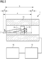
- Figure 2 illustrates a schematic drawing of another MR system 1 comprising a movable patient support 2 in a first position 3 and a second position 4 according to embodiments of the invention.
- the MR system 1 illustrated in Figure 2 is designed similar to MR system 1 illustrated in Figure 1 , wherein MR system 1 comprises a movable patient support 2, a magnet 10, a homogeneity volume 22, an examination volume 21, a memory (16) configured to store program code, and an MR controller (13) coupled with the memory (16) and configured to execute the program code.
- the patient support 2 can be located at different positions within MR system 1. For example the patient support 2 can be located at a first position 3 within MR system 1, as shown in Figure 2 , or patient support 2 can be located at a second position 4 within MR system 1 differing from the first position 3 by a displacement d.
- B DCS B DCS
- TP B table
- B table TP 1, SHIM move
- B DCS SHIM stat
- the spatial extent of the magnetic field B table ( TP ) is limited to the spatial extent of the measured field map and thus to the homogeneity volume. A calculation of the field map over the total homogeneity volume is not possible. However, if the next diagnostic measurement at table position TP2 requires information about a region with limited extent along the z-direction only, then the information measured before can still be sufficient.
- a field map is determined over a range in z-direction extending over 30 cm, i.e. the magnetic field is known over +/- 15 cm.
- the field map can be determined in a range from -5 cm to +25 cm. If the second measurement should only cover a centered stack of layers with an extension of 10 cm, then no new field map has to be measured.
- Figure 3 illustrates a schematic drawing of the MR system 1 of Figure 2 with corresponding magnetic field maps, according to embodiments of the invention.
- a first resulting field map 23 corresponds to a first position of the patient support 2 in MR system 1.
- the patient support is disposed at a second position 4.
- the position dependent magnetic field map which can be only dependent of elements moved together with the patient support 2 is also displaced by displacement d.
- the MR system 1 can therefore determine a second magnetic field, when the movable patient support 2 is located at a second position 4 different from the first position 3, using the stationary field map 24 and the position dependent field map 25.
- execution of the program code by the MR controller 13 can cause the MR system 1 to perform the method according to the following steps.
- a first resulting field map 23 including position dependent information about a magnetic field distribution in homogeneity volume 22 including examination volume 21 of the MR system 1 is provided when the movable patient support 2 with examination subject 12 is located at a first position 3.
- a stationary field map 24 including information about a magnetic field distribution in homogeneity volume 22 is provided, which is independent of the position of the movable patient support 2.
- the stationary field map includes magnetic field components of the stationary shim coils, and therefore, even when the currents through the stationary field coils change, the changed stationary field map can be calculated using the changed currents through the stationary shim coils.
- the position dependent field map 25 includes magnetic field components of the movable shim coils, i.e. Coilshims, wherein when the currents through the movable shim coils change, the changed position dependent field map can be calculated using the changed currents through the movable shim coils.
- a position dependent field map 25 including information about a magnetic field distribution in homogeneity volume 22 mainly influenced by a position of the movable patient support 2 is determined using the stationary field map 24 and the first resulting field map 23.
- a second resulting field map 26 in the homogeneity volume 22 is determined when the movable patient support 2 is located at a second position 4 different from the first position 3, using the stationary field map 24 and the position dependent field map 25.
- the second resulting field map is determined in a volume, which is smaller than the homogeneity volume 22, in particular as small as the intersection of stationary field map 24 and position dependent field map 25.
- the above-described method can be performed for an arbitrary volume within MR system 1 other than the homogeneity volume 22, in particular, a second resulting field map can be determined for an arbitrary other volume than homogeneity volume, e.g. only the examination volume 21.
- Figure 4 schematically illustrates a flow chart with steps for performing a method for determining a field map in an MR system 1 with a movable patient support 2, according to embodiments of the invention.
- step S10 a first resulting field map 23 including position dependent information about a magnetic field distribution in an homogeneity volume 22 including an examination volume 21 of the MR system 1 is provided when the movable patient support 2 is located at a first position 3.
- step S30 a stationary field map 24 including information about a magnetic field distribution in the homogeneity volume 22 is provided, which is independent of the position of the movable patient support 2 and includes magnetic field components generated by stationary shim coils, as described above.
- step S40 a position dependent field map 25 including information about a magnetic field distribution in the homogeneity volume 22 mainly influenced by a position of the movable patient support 2 is determined using the stationary field map 24 and the first resulting field map 23.
- step S50 a second resulting field map 26 in the homogeneity volume 22 is determined when the movable patient support 2 is located at a second position 4 different from the first position 3, using the stationary field map 24 and the position dependent field map 25.
- the method ends in step S90.
- the stationary contributions of the basic magnetic field can slightly change due to external influences, e.g. installation of another large device in the immediate neighborhood.
- Figure 5 schematically illustrates a flow chart with steps for performing a method for determining a change of a stationary magnetic field 24 in a MR system 1 with a movable patient support 2, according to embodiments of the invention.
- step S10 a resulting field map 23 is provided for each of a plurality of different positions of the movable patient support 2, wherein the resulting field map 23 is based on a stationary magnetic field 24 substantially not influenced by position of the movable patient support 2 and a position dependent magnetic field 25 mainly influenced by each position of the movable patient support 2.
- step S70 the plurality of resulting field maps 23 is averaged, i.e. an average is calculated between a plurality of resulting magnetic field values for each voxel.
- step S80 a change of the stationary magnetic field 24 of the MR system 1 is determined based on the average of the plurality of resulting field maps 23. The method ends in step S90.
- Determining a position dependent field map can comprise calculating a difference between the first resulting field map and the stationary field map. Calculating a difference between the first resulting field map and the stationary field map provides efficient determination of position dependent magnetic field components in the homogeneity volume of the MR system.
- the second resulting field map can be determined based on a displacement between the first and the second position of the movable patient support.
- the displacement takes place substantially in the z-direction of the MR system, in other embodiments, i.e. in open C-shaped MR systems, the displacement can take place two dimensions, wherein the method according to the invention can be applied to any displacement.
- the second resulting field map can be determined using the position dependent field map, wherein the position of the position dependent field map is shifted relative to the stationary field map by the displacement of the movable patient support. Shifting the position of the position dependent field map according to the displacement of the movable patient support, allows to more reliably and efficiently determine a magnetic field map and corresponding shim settings based on displacement of the patient support.
- the position dependent field map can be substantially only influenced by the position of the movable patient support and components such as Coilshims, which are moved together with the patient support, relative to the stationary elements of the MR system.
- stationary magnetic field components which are based on stationary, non-movable elements in the MR-system, do not substantially influence the position dependent field map
- other magnetic field components which are based on elements movable with the patient support, such as Coilshims, the patient support itself and the patient mainly influence the position dependent field map.
- a second resulting field map can be only determined using the stationary field map and the position dependent field map, when the displacement is smaller than a movement threshold determined based on a following examination volume.
- the second resulting field map can only be determined, if the adjustment volume for the following examining volume is within the intersection volume of the stationary field map and the position dependent field map.
- the threshold can be determined based on the relation of the adjustment volume to the intersection volume.
- Using such a threshold provides more reliability and preciseness for the method, as positions of the patient support are excluded, where the patient support is moved as far to a position, where not enough information is available in the homogeneity volume to precisely determine a magnetic field map and corresponding shim settings.
- the second resulting field map can be measured using MR signals from the homogeneity volume when the displacement is larger than a movement threshold determined based on the following examination volume.
- the threshold is chosen as large as possible.
- MDS adjustments an isocentrically measured volume, which extends only a few centimeters in z-direction, is measured.
- a plurality of N magnetic fields corresponding to different table positions B table ( TP 1, SHIM move ) to B table ( TPN,SHIM move ) can be determined successively while the table moves from one table position to the next table position, preferably the table moves continuously.
- the extensions and distances in z-direction of this plurality of measurements are selected in such a way that a seamless map of the lying inhomogeneities can be calculated from B table ( TP 1, SHIM move ) to B table ( TPN,SHIM move ): B table ( TP 1 - TPN, SHIM move ) .
- the map can correspond to the complete body of a patient, or partial regions of the body of the patient, which are of interest for MR imaging.
- the field map B ( x,y,z,SHIM,TP ) can be determined for each table position, and a complete shim calculation is performed thereon.
- a resulting field map can be provided for each of a plurality of different positions of the movable patient support, a stationary field map including information about a magnetic field distribution in a homogeneity volume of the MR system, which is independent of the positions of the movable patient support can be provided, an overall position dependent field map including information about a magnetic field distribution mainly influenced by each position of the movable patient support can be determined using the stationary field map and the plurality of resulting field maps, and an intermediate resulting field map can be determined while the movable patient support is located at an intermediate position between two positions of the movable patient support, using the stationary field map and the overall position dependent field map.
- a plurality of position dependent field maps for a plurality of different patient support which furthermore can be merged to an overall position dependent field map, enables determining accurate shim settings for all possible patient support positions lying between the measured patient support positions.
- the different positions of the movable patient support are adjacent to each other or overlapping each other, whereby only one reference scan can be sufficient for a plurality of measurements on an examining position, without the need of recurring reference scans to determine new shim settings when the patient support is moved to an arbitrary intermediate position.
- the method is performed using substantially continuous movement of the movable patient support, enabling a smooth transition for an examination subject and a more efficient method for determining new shim settings by only one reference scan.
- a method for determining a field map and corresponding shim settings in a MR system comprising a movable patient support wherein an absolute BO field map is used and magnetic field inhomogeneities are first separated into stationary magnetic field components and table position dependent magnetic field components, in order to then add these components again to determine a magnetic field map based on a new desired table position.
- a significantly larger value for the table movement threshold can be used resulting in a saving of adjustment time and thus gives the customer more time for imaging, which can be used to more precisely and effectively determine a magnetic field map and corresponding shim settings, perform additional diagnostic measurements, or achieve shorter examination times.
Landscapes
- Physics & Mathematics (AREA)
- Health & Medical Sciences (AREA)
- Life Sciences & Earth Sciences (AREA)
- Condensed Matter Physics & Semiconductors (AREA)
- General Physics & Mathematics (AREA)
- High Energy & Nuclear Physics (AREA)
- Engineering & Computer Science (AREA)
- Nuclear Medicine, Radiotherapy & Molecular Imaging (AREA)
- General Health & Medical Sciences (AREA)
- Signal Processing (AREA)
- Radiology & Medical Imaging (AREA)
- Biophysics (AREA)
- Pathology (AREA)
- Biomedical Technology (AREA)
- Heart & Thoracic Surgery (AREA)
- Medical Informatics (AREA)
- Molecular Biology (AREA)
- Surgery (AREA)
- Animal Behavior & Ethology (AREA)
- Public Health (AREA)
- Veterinary Medicine (AREA)
- Magnetic Resonance Imaging Apparatus (AREA)
Abstract
Description
- The present invention relates to a method for determining a magnetic field map in a MR system, and in particular to a method for determining a magnetic field map in a MR system based on position of a movable patient support of the MR system. Further, a corresponding MR system, computer program product, and electronically readable data carrier are provided.
- Magnetic Resonance Imaging (MRI) is based on spins of atomic nuclei aligned in a magnetic BO field. For many applications, homogeneity of the magnetic BO field, which means constant field intensity in a large three-dimensional space, the so-called homogeneity volume of the MR system, is crucial for MR image quality and also for spatial registration of MR images in regard of MR image distortions.
- Common superconducting magnets allow magnetic field homogeneities with deviations of less than 1 ppm over a homogeneity volume of about 30-40 cm spherical diameter within a MR system. Accordingly, problems with fat saturation arise in particular in regions of the anatomy located in the periphery of the above homogeneity volume, such as a shoulder of an examination subject, which cannot be disposed in the center of the homogeneity volume because of the lack of space in the patient tunnel of an MR system.
- The body of an examination subject generates additional magnetic field inhomogeneities when introduced into the magnetic BO field. The human tissue has a relative magnetic permeability different from air. As a result, the discontinuities of air and tissue lead to strong BO distortions. Also the inhomogeneous distribution of water, air, bone and fat in the human body leads to a different distortion of the magnetic BO field for each examination subject.
- In order to suppress BO inhomogeneity caused by the tissue, shim coils, which can be part of a gradient coil, or local shim coils, which can be extra coils or part of local coils, so-called CoilShim, are commonly used. In order to obtain optimal results, the current through the shim coils is optimized so that the BO field becomes as homogeneous as possible in the homogeneity volume.
- Different distortions of the magnetic fields can be taken into account. First, there are stationary known distortions, such as the fundamental magnetic field of the magnet of the MR system, the non-ideal fields of gradient coils and stationary shim coils, and all further magnetic field inhomogeneities, which are stationary and known in the so-called device coordinate system (DCS). As a different example, distortions of the magnetic field can occur when the examination subject or other objects are moved together with a movable patient support of the MR system.
- Accordingly, a description of the magnetic fields can be provided as follows:

- Therein, B(x,y,z,SHIM,TP) corresponds to the actual distribution of the magnetic field in the patient tunnel with all contributions from the scanner and the examination subject. This actual distribution is determined by a field map measurement and it is dependent on overall shim condition SHIM = (SHIMstat, SHIMmove), consisting of a contribution SHIMstat, which in a typical embodiment is generated by three stationary gradient shim coils, and a contribution SHIMmove, which in a typical embodiment is generated by five 2nd order shim coil channels (Coilshims) and in another embodiment is generated by two 2nd order shim coil channels (Coilshims), which are moved together with the patient support, and table position TP. Further, the magnetic field Bhom corresponds to an ideal homogeneous magnetic field, which is not further considered here and, therefore, is integrated into the magnetic field BDCS (SHIM stat). Magnetic field B'DCS (SHIM stat) contains all inhomogeneities which are stationary in the DCS, i.e. which do not change when a movable patient support is moved. These are, for the most part, already known or can be determined by calibration measurements. This is also dependent on the shim state SHIM, e.g. the shim currents. The magnetic field BDCS (SHIM stat) contains the homogeneous magnetic field Bhom for simplification. And magnetic field Btable (TP,SHIM move) contains all inhomogeneities that move along with a movement of a movable patient support of the MR system, in particular a movement of the patient support with the examination subject in the DCS. These inhomogeneities are dominated by the susceptibility distribution of the examination subject and therefore are largely undetermined. Btable (TP,SHIM move) is known in the table coordinate system, in particular, when the position of the Coilshims and the current through the Coilshims are known, apart from patient movement and other arbitrary distortions. In particular Btable (TP,SHIM move) moves in the same extent as the table in the DCS and is, therefore, directly dependent on the table position TP in the MR system.
- With common MR imaging methods for determining a magnetic field map in a MR system, these two magnetic field components BDCS and Btable are not any further separable and thus the following disadvantages arise according to these known MR imaging methods.
- As a first disadvantage, the field map, on which shimming is based, has to be measured newly after movement of the table, with a small tolerance threshold.
- Further, field maps based on so-called Move-During-Scan (MDS) adjustments are always isocentrically determined, and accordingly only have a few centimeters of coverage in z-direction of the table, and can therefore only be used isocentrically.
- Commonly, the magnetic field at a certain table position are determined by means of a 2-echo field map measurement, as described for example in the document
US 5614827 A . Therein, a phase difference between a first and second echo is used as measure of the magnetic field homogeneity and the phase difference is further spatially differentiated by a respective difference to each neighbor in each of the three spatial directions, due to occurring phase wraps, in order to determine shim settings. - These data are commonly used in combination with likewise spatially differentiated coil fields to calculate shim currents. In particular, due to the occurring phase wraps and the subsequent spatial differentiation, no direct determination of the magnetic field is possible.
- In the 2-echo field map measured as described above, the inhomogeneities Btable, which are caused by distortions of the magnetic field by the examination subject and the patient support, are superposed with inhomogeneities of the basic magnetic field BO and further components BDCS. These two components of the magnetic field are not uniquely separable in the 2-echo method due to the occurring phase wraps.
- If the table position changes, then the field map is remeasured since in the DCS the following applies:

- For very small table movements, it can be assumed that Btable (TP1,SHIM move) and Btable (TP2,SHIM move) do not differ much, and thus a limit value for ΔTP is defined, so that the field map is not measured anew for reasons of time savings in the case of very small table movements.
- In the case of the MDS adjustments, only the gradients and not the 2nd order shims are used because of the above restrictions. Furthermore, the shim setting is calculated based on the information of a field map extending only a few centimeters in the z-direction, but is used for larger volumes. This results in a corresponding loss of quality.
- Methods to determine a field map are known from
US 20150015257 A1 andUS 20150077115 A1 . - Accordingly there is a need to provide a method for a MR system with a movable patient support, which provides a high-quality and more efficient determination of a magnetic field map compared to known methods and systems.
- This need is met by the subject matter of the independent claims. Further advantageous features are subject matter of the dependent claims.
- According to a first aspect, a method for determining a field map in a MR system comprising a movable patient support is provided. Therein, in a first step a first resulting field map including position dependent information about a magnetic field distribution in an homogeneity volume including an examination volume of the MR system is provided when the movable patient support is located at a first position. In a further step, a stationary field map including information about a magnetic field distribution in the homogeneity volume is provided, which is independent of the position of the movable patient support. In another step, a position dependent field map including information about a magnetic field distribution in the homogeneity volume mainly influenced by a position of the movable patient support is determined using the stationary field map and the first resulting field map. In a further step, a second resulting field map in the homogeneity volume is determined when the movable patient support is located at a second position different from the first position, using the stationary field map and the position dependent field map.
- Thereby, an improved method for determining a magnetic field map in a MR system is provided, according to which an absolute BO field map is used and magnetic field inhomogeneities are first separated into stationary magnetic field components and patient support position dependent magnetic field components, in order to then add these components again to determine a magnetic field map based on a new desired table position based on a calculation and not a measurement, as commonly carried out. Further, previous measurements of the magnetic field map based on certain table positions can be saved and reused, even if the table is moved more than a specified table movement threshold, which commonly initiates a new magnetic field map measurement. Effectively, a significantly larger value for the patient support movement threshold can be used, i.e. the patient support can be moved to a greater extend before a new measurement of the magnetic field map has to be initiated. This results in saving of adjustment time and thus gives the customer more time for imaging protocols - without any qualitative degradation. Especially in the case of the scan-at-center concept, a larger value for the table movement threshold can be particularly helpful measuring time can be saved significantly. Furthermore, the determined magnetic field map can be used for the calculation of high-quality shim settings, so that an efficient and precise homogenization of the magnetic BO field is provided.
- According to a second aspect, a method for determining a change of a stationary magnetic field in a MR system with a movable patient support is disclosed. Therein, in a first step a resulting field map is provided for each of a plurality of different positions of the movable patient support, wherein the resulting field map is based on a stationary magnetic field substantially not influenced by position of the movable patient support and a position dependent magnetic field mainly influenced by each position of the movable patient support. In a further step the plurality of resulting field maps is averaged, i.e. an average is calculated between a plurality of resulting magnetic field values for each voxel. In another step, a change of the stationary magnetic field of the MR system is determined based on the average of the plurality of resulting field maps.
- Thereby, an improved method for determining a change of a stationary magnetic field in a MR system is provided, according to which an absolute BO field map is used and magnetic field inhomogeneities are separated into stationary magnetic field components and table position dependent magnetic field components, in order to determine a change of the stationary magnetic field of the MR system. The influences of non-stationary magnetic fields are averaged, leaving a measure for the actual scanner inhomogeneity and thus stationary contributions of the basic magnetic field due to external influences, e.g. installation of another large device in the immediate neighborhood, can be reliably detected.
- The MR system for determining a magnetic field map described in the second aspect of the invention can be configured to perform any of the methods described in the first aspect of the invention above. For such systems for determining a magnetic field map, technical effects can be achieved, which correspond to the technical effects described for the method for determining a magnetic field map according to the first aspect of the invention.
- According to a third aspect, a MR system for determining a magnetic field map is provided, wherein the system comprises the following elements. The MR system comprises a memory configured to store program code, and least one MR controller coupled with the memory. Therein, the at least one MR controller is configured to execute the program code, wherein execution of the program code causes the MR system to perform the following steps. In a first step, a first resulting field map including position dependent information about a magnetic field distribution in a homogeneity volume including an examination volume of the MR system is provided when the movable patient support is located at a first position. In a further step, a stationary field map including information about a magnetic field distribution in the homogeneity volume is provided, which is independent of the position of the movable patient support. In another step, a position dependent field map including information about a magnetic field distribution in the homogeneity volume mainly influenced by a position of the movable patient support is determined using the stationary field map and the first resulting field map. In a further step, a second resulting field map in the homogeneity volume is determined when the movable patient support is located at a second position different from the first position, using the stationary field map and the position dependent field map.
- According to a fourth aspect, a computer program product is provided, which comprises program code, which can be loaded directly into a memory of a MR system, wherein execution of the program code by a MR controller causes the MR system to perform one of the methods as described in the first aspect of the invention above.
- According to a fifth aspect, an electronically readable data carrier is provided with electronically readable control information stored thereon, which are configured in such a way that they execute one of the methods as described in the first aspect of the invention above when using the data carrier in a MR controller of a MR system.
- Although specific features described in the above summary and the following detailed description are described in connection with specific embodiments and aspects of the present invention, it should be understood that the features of the exemplary embodiments and aspects may be combined with each other unless specifically noted otherwise.
- The present invention will now be described in more detail with reference to the accompanying drawings.
-
Figure 1 illustrates a schematic drawing of an MR system comprising a movable patient support with which a method for determining a field map can be carried out, according to embodiments of the invention. -
Figure 2 illustrates a schematic drawing of another MR system comprising a movable patient support in a first and second position, according to embodiments of the invention. -
Figure 3 illustrates a schematic drawing of the MR system ofFigure 2 with corresponding magnetic field maps, according to embodiments of the invention. -
Figure 4 schematically illustrates a flow chart with steps for performing a method for determining a field map in an MR system with a movable patient support, according to embodiments of the invention. -
Figure 5 schematically illustrates a flow chart with steps for performing a method for determining a change of a stationary magnetic field in a MR system with a movable patient support, according to embodiments of the invention. - In the following, concepts in accordance with exemplary embodiments of the invention will be explained in more detail and with reference to the accompanying drawings.
- The drawings are to be regarded as being schematic representations and elements illustrated in the drawings are not necessarily shown to scale. Rather, the various elements are represented such that their function and general purpose become apparent to a person skilled in the art. Any connection or coupling between functional blocks, devices, components, modules or other physical or functional units shown in the drawings or described herein may also be implemented by an direct or indirect connection or coupling. A coupling between components may also be established over a wireless connection. Functional blocks may be implemented in hardware, firmware, software, or a combination thereof.
-
Figure 1 illustrates a schematic drawing of an MR system 1 comprising a movablepatient support 2 with which a method for determining a field map can be carried out, according to embodiments of the invention. - Referring to
Figure 1 , an MR system 1 is described, with which, as explained below, a magnetic field map can be determined based on position of a patient support according to the invention. An examination subject 12, or more generally an examining object, is located in an examining tunnel of MR system 1. The MR system 1 comprises amagnet 10 for generating a basic field B0, whereby an examination subject 12 is positioned on apatient support 2, or so-called table of the MR-system. Inside the magnet, ahomogeneity volume 22 comprising anexamination volume 21 is formed. Thepatient support 2 is moved in the center of themagnet 10 into thehomogeneity volume 22 including anexamination volume 21, such that the MR system receives spatially coded magnetic resonance signals from theexamination volume 21. By irradiation of RF pulse sequences and switching of magnetic field gradients, the nuclear spins in theexamination volume 21 can be deflected from the equilibrium position and currents induced by the magnetization generated by the base field BO and the return to the equilibrium position can be converted into magnetic resonance signals in the receiving coils. The general mode of operation for the generation of MR images and the detection of the magnetic resonance signals are known to a person skilled in the art, so that a detailed explanation thereof is omitted in the following. - The MR system 1 comprises a
MR controller 13, which is used for controlling the MR system 1. Thecentral MR controller 13, which is adapted to perform the method described below for determining a field map, further comprises agradient controller 14 for controlling and switching the magnetic field gradients, and anRF controller 15 for controlling and irradiating the RF pulses for deflecting the nuclear spins from the equilibrium position. In amemory unit 16, for example the imaging sequences necessary for recording the MR images can be stored, as well as the programs which are necessary for the operation of the MR system 1. Arecording unit 17 controls the image recording and thus controls the sequence of the magnetic field gradients and RF pulses and the reception intervals of MR signals as a function of the selected imaging sequences. Therecording unit 17 also controls thegradient control 14 and theHF control 15. MR images which can be displayed on adisplay 18 can be calculated in acomputing unit 20, whereby an operator operates the MR system via aninput unit 19 can. Thememory 16 can have imaging sequences and program modules which carry out the method according to the invention when executed in thecomputing unit 20 of one of the modules shown. TheRF controller 15 may further be configured to improve the method for determining a magnetic field map, as is explained in the following in detail. In particular,memory 16 stores control information which can be derived from theMR controller 13. Further, therecording unit 17 is adapted to perform the following method for determining a magnetic field map. - According to the invention, the MR system of
Figure 1 is designed in such a way that, during the execution of the control information in theMR controller 13, a method for determining a field map according to embodiments of the invention is performed. -
Figure 2 illustrates a schematic drawing of another MR system 1 comprising a movablepatient support 2 in afirst position 3 and asecond position 4 according to embodiments of the invention. - The MR system 1 illustrated in
Figure 2 is designed similar to MR system 1 illustrated inFigure 1 , wherein MR system 1 comprises a movablepatient support 2, amagnet 10, ahomogeneity volume 22, anexamination volume 21, a memory (16) configured to store program code, and an MR controller (13) coupled with the memory (16) and configured to execute the program code. Thepatient support 2 can be located at different positions within MR system 1. For example thepatient support 2 can be located at afirst position 3 within MR system 1, as shown inFigure 2 , orpatient support 2 can be located at asecond position 4 within MR system 1 differing from thefirst position 3 by a displacement d. - The basic idea is the separation of BDCS (SHIM) and Btable (TP). This is made possible by use of a so-called absolute field map, which can for example be based on the 3-echo method, as described for example in the document
US 20150204955 A1 , or other methods as known in the art. A further prerequisite is the knowledge of BDCS (SHIM). - This is the case, since the significant contributions are known: The basic magnetic field is measured during installation of the MR system and the non-ideal components of the gradients and shims are also known. Thus, the table-fixed inhomogeneities can be calculated from the measured absolute field map and handled separately:

- These two components Btable (TP1,SHIM move) and BDCS (SHIM stat) are stored separately and used for further calculation of a field map at a different table position:

- Assuming that the table only moves along the z-coordinate, the following relation applies to table positions TP1 at Z TP1 and TP2 at Z TP2 :

- The spatial extent of the magnetic field Btable (TP) is limited to the spatial extent of the measured field map and thus to the homogeneity volume. A calculation of the field map over the total homogeneity volume is not possible. However, if the next diagnostic measurement at table position TP2 requires information about a region with limited extent along the z-direction only, then the information measured before can still be sufficient.
- As an example, in a first measurement a field map is determined over a range in z-direction extending over 30 cm, i.e. the magnetic field is known over +/- 15 cm. In a second measurement at table position TP2 = TP1 + 10 cm, according to the invention, the field map can be determined in a range from -5 cm to +25 cm. If the second measurement should only cover a centered stack of layers with an extension of 10 cm, then no new field map has to be measured.
- For strongly varying table positions, there is not enough information to calculate B(x,y,z,SHIM,TP2). A new measurement is therefore necessary in this case. If TP1 and TP2 do not differ by more than the extension of the field map measurement in z-direction minus a tolerance value, then Btable (TP1,SHIM move) and Btable (TP2,SHIM move) complement each other to a correspondingly larger information, which is longer in z-direction. Then, a field map B(x,y,z,SHIM,TP3) can also be calculated directly at a table position TP3 between TP1 and TP2.
-
Figure 3 illustrates a schematic drawing of the MR system 1 ofFigure 2 with corresponding magnetic field maps, according to embodiments of the invention. - A first resulting
field map 23 corresponds to a first position of thepatient support 2 in MR system 1. After displacing thepatient support 2 by displacement d, the patient support is disposed at asecond position 4. Along with thepatient support 2, the position dependent magnetic field map, which can be only dependent of elements moved together with thepatient support 2, is also displaced by displacement d. The MR system 1, as illustrated inFigures 2 and3 , can therefore determine a second magnetic field, when the movablepatient support 2 is located at asecond position 4 different from thefirst position 3, using thestationary field map 24 and the positiondependent field map 25. In particular, execution of the program code by theMR controller 13 can cause the MR system 1 to perform the method according to the following steps. In a first step a first resultingfield map 23 including position dependent information about a magnetic field distribution inhomogeneity volume 22 includingexamination volume 21 of the MR system 1 is provided when the movablepatient support 2 with examination subject 12 is located at afirst position 3. In a further step, astationary field map 24 including information about a magnetic field distribution inhomogeneity volume 22 is provided, which is independent of the position of the movablepatient support 2. In particular, the stationary field map includes magnetic field components of the stationary shim coils, and therefore, even when the currents through the stationary field coils change, the changed stationary field map can be calculated using the changed currents through the stationary shim coils. Likewise, the positiondependent field map 25 includes magnetic field components of the movable shim coils, i.e. Coilshims, wherein when the currents through the movable shim coils change, the changed position dependent field map can be calculated using the changed currents through the movable shim coils. In another step, a positiondependent field map 25 including information about a magnetic field distribution inhomogeneity volume 22 mainly influenced by a position of the movablepatient support 2 is determined using thestationary field map 24 and the first resultingfield map 23. In a further step, a second resultingfield map 26 in thehomogeneity volume 22 is determined when the movablepatient support 2 is located at asecond position 4 different from thefirst position 3, using thestationary field map 24 and the positiondependent field map 25. In one embodiment, the second resulting field map is determined in a volume, which is smaller than thehomogeneity volume 22, in particular as small as the intersection ofstationary field map 24 and positiondependent field map 25. In another embodiment, the above-described method can be performed for an arbitrary volume within MR system 1 other than thehomogeneity volume 22, in particular, a second resulting field map can be determined for an arbitrary other volume than homogeneity volume, e.g. only theexamination volume 21. -
Figure 4 schematically illustrates a flow chart with steps for performing a method for determining a field map in an MR system 1 with a movablepatient support 2, according to embodiments of the invention. - The method starts in step S10. In step S20, a first resulting
field map 23 including position dependent information about a magnetic field distribution in anhomogeneity volume 22 including anexamination volume 21 of the MR system 1 is provided when the movablepatient support 2 is located at afirst position 3. In step S30, astationary field map 24 including information about a magnetic field distribution in thehomogeneity volume 22 is provided, which is independent of the position of the movablepatient support 2 and includes magnetic field components generated by stationary shim coils, as described above. In step S40, a positiondependent field map 25 including information about a magnetic field distribution in thehomogeneity volume 22 mainly influenced by a position of the movablepatient support 2 is determined using thestationary field map 24 and the first resultingfield map 23. In step S50, a second resultingfield map 26 in thehomogeneity volume 22 is determined when the movablepatient support 2 is located at asecond position 4 different from thefirst position 3, using thestationary field map 24 and the positiondependent field map 25. The method ends in step S90. - The stationary contributions of the basic magnetic field can slightly change due to external influences, e.g. installation of another large device in the immediate neighborhood.
- If averaging is carried out over many ments B(x,y,z,SHIM,TP), then the influences of non-stationary magnetic fields are averaged, leaving a measure for the actual scanner inhomogeneity. This can be carried out continuously and thus possible changes in the scanner inhomogeneity can be detected. With self-learning algorithms, small changes could, if necessary, be directly implemented as corrections. In the case of large changes, a new determination of the basic magnetic field could be triggered.
-
Figure 5 schematically illustrates a flow chart with steps for performing a method for determining a change of a stationarymagnetic field 24 in a MR system 1 with a movablepatient support 2, according to embodiments of the invention. - The method starts in step S10. In step S60, a resulting
field map 23 is provided for each of a plurality of different positions of the movablepatient support 2, wherein the resultingfield map 23 is based on a stationarymagnetic field 24 substantially not influenced by position of the movablepatient support 2 and a position dependentmagnetic field 25 mainly influenced by each position of the movablepatient support 2. In step S70, the plurality of resulting field maps 23 is averaged, i.e. an average is calculated between a plurality of resulting magnetic field values for each voxel. In step S80, a change of the stationarymagnetic field 24 of the MR system 1 is determined based on the average of the plurality of resulting field maps 23. The method ends in step S90. - From the above said, some general conclusions can be drawn:
- The first resulting field map can be an absolute field map of the resulting magnetic field in the homogeneity volume as used for a MR measurement in the examination volume of the MR system, it can in particular be measured by a 3-echo-method as known in the art. By providing an absolute field map as described above, a resulting magnetic field in the homogeneity volume and corresponding shim settings can be determined more reliably and more precisely.
- Determining a position dependent field map can comprise calculating a difference between the first resulting field map and the stationary field map. Calculating a difference between the first resulting field map and the stationary field map provides efficient determination of position dependent magnetic field components in the homogeneity volume of the MR system.
- The second resulting field map can be determined based on a displacement between the first and the second position of the movable patient support. In some embodiments the displacement takes place substantially in the z-direction of the MR system, in other embodiments, i.e. in open C-shaped MR systems, the displacement can take place two dimensions, wherein the method according to the invention can be applied to any displacement. By using the displacement between the first and the second position of the movable patient support, the information about position dependent magnetic field components corresponding to the patient support and the examination subject on the patient support used to more reliably and efficiently determine a magnetic field map and corresponding shim settings based on displacement of the patient support.
- The second resulting field map can be determined using the position dependent field map, wherein the position of the position dependent field map is shifted relative to the stationary field map by the displacement of the movable patient support. Shifting the position of the position dependent field map according to the displacement of the movable patient support, allows to more reliably and efficiently determine a magnetic field map and corresponding shim settings based on displacement of the patient support.
- The second resulting field map can be determined according to the relation

- The position dependent field map can be substantially only influenced by the position of the movable patient support and components such as Coilshims, which are moved together with the patient support, relative to the stationary elements of the MR system. Therein, in particular stationary magnetic field components, which are based on stationary, non-movable elements in the MR-system, do not substantially influence the position dependent field map, and other magnetic field components which are based on elements movable with the patient support, such as Coilshims, the patient support itself and the patient mainly influence the position dependent field map. By taking into account mainly only magnetic field components, which are dependent on position of the patient support, determination of a magnetic field map and corresponding shim settings based on displacement of the patient support can be performed more reliably and efficiently.
- A second resulting field map can be only determined using the stationary field map and the position dependent field map, when the displacement is smaller than a movement threshold determined based on a following examination volume. In another embodiment, the second resulting field map can only be determined, if the adjustment volume for the following examining volume is within the intersection volume of the stationary field map and the position dependent field map. In this case, the threshold can be determined based on the relation of the adjustment volume to the intersection volume.
- Using such a threshold provides more reliability and preciseness for the method, as positions of the patient support are excluded, where the patient support is moved as far to a position, where not enough information is available in the homogeneity volume to precisely determine a magnetic field map and corresponding shim settings.
- The second resulting field map can be measured using MR signals from the homogeneity volume when the displacement is larger than a movement threshold determined based on the following examination volume. In particular, in order to enable the calculation of the second resulting field map, the threshold is chosen as large as possible.
For the so-called MDS adjustments, an isocentrically measured volume, which extends only a few centimeters in z-direction, is measured. According to the above-described method using absolute field maps, a plurality of N magnetic fields corresponding to different table positions Btable (TP1,SHIM move) to Btable (TPN,SHIM move) can be determined successively while the table moves from one table position to the next table position, preferably the table moves continuously. - The extensions and distances in z-direction of this plurality of measurements are selected in such a way that a seamless map of the lying inhomogeneities can be calculated from Btable (TP1,SHIM move) to Btable (TPN,SHIM move): Btable (TP1 - TPN, SHIM move). The map can correspond to the complete body of a patient, or partial regions of the body of the patient, which are of interest for MR imaging. Thus, with one MDS-Adjustment-Scan the field map B(x,y,z,SHIM,TP) can be determined for each table position, and a complete shim calculation is performed thereon.
- Accordingly, a resulting field map can be provided for each of a plurality of different positions of the movable patient support, a stationary field map including information about a magnetic field distribution in a homogeneity volume of the MR system, which is independent of the positions of the movable patient support can be provided, an overall position dependent field map including information about a magnetic field distribution mainly influenced by each position of the movable patient support can be determined using the stationary field map and the plurality of resulting field maps, and an intermediate resulting field map can be determined while the movable patient support is located at an intermediate position between two positions of the movable patient support, using the stationary field map and the overall position dependent field map. Using a plurality of position dependent field maps for a plurality of different patient support, which furthermore can be merged to an overall position dependent field map, enables determining accurate shim settings for all possible patient support positions lying between the measured patient support positions.
- The different positions of the movable patient support are adjacent to each other or overlapping each other, whereby only one reference scan can be sufficient for a plurality of measurements on an examining position, without the need of recurring reference scans to determine new shim settings when the patient support is moved to an arbitrary intermediate position.
- The method is performed using substantially continuous movement of the movable patient support, enabling a smooth transition for an examination subject and a more efficient method for determining new shim settings by only one reference scan.
- Summarizing, a method for determining a field map and corresponding shim settings in a MR system comprising a movable patient support is provided, wherein an absolute BO field map is used and magnetic field inhomogeneities are first separated into stationary magnetic field components and table position dependent magnetic field components, in order to then add these components again to determine a magnetic field map based on a new desired table position. Effectively, a significantly larger value for the table movement threshold can be used resulting in a saving of adjustment time and thus gives the customer more time for imaging, which can be used to more precisely and effectively determine a magnetic field map and corresponding shim settings, perform additional diagnostic measurements, or achieve shorter examination times.
Claims (17)
- Method for determining a field map in a MR system (1) comprising a movable patient support (2), the method comprising:- providing a first resulting field map (23) including position dependent information about a magnetic field distribution in an homogeneity volume (22) including an examination volume (21) of the MR system (1) when the movable patient support (2) is located at a first position (3);- providing a stationary field map (24) including information about a magnetic field distribution in the homogeneity volume (22), which is independent of the position of the movable patient support (2);- determining a position dependent field map (25) including information about a magnetic field distribution in the homogeneity volume (22) mainly influenced by a position of the movable patient support (2) using the stationary field map (24) and the first resulting field map (23); and- determining a second resulting field map (26) in the homogeneity volume (22) when the movable patient support (2) is located at a second position (4) different from the first position (3), using the stationary field map (24) and the position dependent field map (25).
- Method according to claim 1, wherein the first resulting field map (23) is an absolute field map of the resulting magnetic field in the homogeneity volume (21) as used for a MR measurement in the examination volume (21) of the MR system (1).
- Method according to one of the preceding claims, wherein determining a position dependent field map (25) comprises calculating a difference between the first resulting field map (23) and the stationary field map (24).
- Method according to one of the preceding claims, wherein the second resulting field map (26) is determined based on a displacement (d) between the first and the second position (3, 4) of the movable patient support (2).
- Method according to claim 4, wherein the second resulting field map (26) is determined using the position dependent field map (25), wherein the position of the position dependent field map (25) is shifted relative to the stationary field map (24) by the displacement (d) of the movable patient support (2).
- Method according to claim 5, wherein the second resulting field map (26) is determined according to the relation

- Method according to one of the preceding claims, wherein the position dependent field map (24) is substantially only influenced by the position of the movable patient support (2) and shim coils moved together with the patient support relative to the stationary elements of the MR system (1).
- Method according to one claims 5 to 7, wherein a second resulting field map (26) is only determined using the stationary field map (24) and the position dependent field map (25), when the displacement (d) is smaller than a movement threshold determined based on a following examination volume.
- Method according to claim 8, wherein the second resulting field map (26) is measured using MR signals from the homogeneity volume (22) when the displacement (d) is larger than the movement threshold determined based on the following examination volume.
- Method according to one of claims 1 to 7, wherein- a resulting field map (23) is provided for each of a plurality of different positions of the movable patient support (2);- a stationary field map (24) including information about a magnetic field distribution in a homogeneity volume (22) of the MR system (1), which is independent of the positions of the movable patient support (2), is provided;- an overall position dependent field map including information about a magnetic field distribution mainly influenced by each position of the movable patient support (2) is determined using the stationary field map (24) and the plurality of resulting field maps (23); and- an intermediate resulting field map is determined while the movable patient support (2) is located at an intermediate position between two positions of the movable patient support (2), using the stationary field map (24) and the overall position dependent field map.
- Method according to claim 10, wherein the different positions of the movable patient support (2) are adjacent to each other or overlapping each other.
- Method according to one of claims 10 or 11, wherein the method is performed using substantially continuous movement of the movable patient support (2).
- Method for determining a change of a stationary magnetic field in a MR system (1) with a movable patient support (2), comprising:- providing a resulting field map (23) for each of a plurality of different positions of the movable patient support (2), wherein the resulting field map (23) is based on a stationary magnetic field (24) substantially not influenced by position of the movable patient support (2) and a position dependent magnetic field (25) mainly influenced by each position of the movable patient support (2);- averaging the plurality of resulting field maps; and- determining a change of the stationary magnetic field (24) of the MR system (1) based on the average of the plurality of resulting field maps (25).
- MR system with a movable patient support (2) for determining a magnetic field map, wherein the MR system (1) comprises a memory (16) configured to store program code, and MR controller (13) coupled with the memory (16) and configured to execute the program code, wherein execution of the program code by the MR controller (13) causes the MR system (1) to perform the following:- providing a first resulting field map (23) including position dependent information about a magnetic field distribution in an homogeneity volume (22) including an examination volume (21) of the MR system (1) when the movable patient support (2) is located at a first position (3);- providing a stationary field map (24) including information about a magnetic field distribution in the homogeneity volume (22), which is independent of the position of the movable patient support (2);- determining a position dependent field map (25) including information about a magnetic field distribution in the homogeneity volume (22) mainly influenced by a position of the movable patient support (2) using the stationary field map (24) and the first resulting field map (23); and- determining a second resulting field map (26) in the homogeneity volume (22) when the movable patient support (2) is located at a second position (4) different from the first position (3), using the stationary field map (24) and the position dependent field map (25).
- MR system with a movable patient support (2) for determining a magnetic field map, wherein the MR system (1) comprises a memory (16) configured to store program code, and MR controller (13) coupled with the memory (16) and configured to execute the program code, wherein execution of the program code by the MR controller (13) causes the MR system (1) to perform the method according to one of claims 2 to 13.
- Computer program product, which comprises program code, which can be loaded directly into a memory (16) of a MR system (1), wherein execution of the program code by a MR controller (13) causes the MR system (1) to perform the method according to one of claims 1 to 13.
- Electronically readable data carrier with electronically readable control information stored thereon which are configured in such a way that they execute the method according to one of claims 1 to 13 when using the data carrier in a MR controller (13) of a MR system (1).
Priority Applications (2)
| Application Number | Priority Date | Filing Date | Title |
|---|---|---|---|
| EP17188159.2A EP3451008B1 (en) | 2017-08-28 | 2017-08-28 | Magnetic field map determination in a mr system |
| US16/106,284 US10989781B2 (en) | 2017-08-28 | 2018-08-21 | Magnetic field map determination in a magnetic resonance system |
Applications Claiming Priority (1)
| Application Number | Priority Date | Filing Date | Title |
|---|---|---|---|
| EP17188159.2A EP3451008B1 (en) | 2017-08-28 | 2017-08-28 | Magnetic field map determination in a mr system |
Publications (2)
| Publication Number | Publication Date |
|---|---|
| EP3451008A1 true EP3451008A1 (en) | 2019-03-06 |
| EP3451008B1 EP3451008B1 (en) | 2020-02-19 |
Family
ID=59713938
Family Applications (1)
| Application Number | Title | Priority Date | Filing Date |
|---|---|---|---|
| EP17188159.2A Active EP3451008B1 (en) | 2017-08-28 | 2017-08-28 | Magnetic field map determination in a mr system |
Country Status (2)
| Country | Link |
|---|---|
| US (1) | US10989781B2 (en) |
| EP (1) | EP3451008B1 (en) |
Families Citing this family (3)
| Publication number | Priority date | Publication date | Assignee | Title |
|---|---|---|---|---|
| CN113466765B (en) * | 2020-03-31 | 2024-12-10 | 通用电气精准医疗有限责任公司 | Magnetic resonance scanning method and system, and computer readable storage medium |
| US11360179B2 (en) | 2020-10-29 | 2022-06-14 | The Mitre Corporation | Systems and methods for estimating magnetic susceptibility through continuous motion in an MRI scanner |
| EP4027161A1 (en) | 2021-01-08 | 2022-07-13 | Koninklijke Philips N.V. | Method for updating a magnetic field map during a mri examination |
Citations (7)
| Publication number | Priority date | Publication date | Assignee | Title |
|---|---|---|---|---|
| US5614827A (en) | 1995-03-30 | 1997-03-25 | Siemens Aktiengesellschaft | Method and apparatus for shimming a magnet system of a nuclear magnetic resonance tomography system |
| US20080015431A1 (en) * | 2006-07-14 | 2008-01-17 | Franz Schmitt | Magnetic resonance apparatus with table movement controlled dependent on magnetic field distribution |
| US20100289492A1 (en) * | 2009-05-13 | 2010-11-18 | Stephan Biber | Method and device for position determination of body matrix coils in mr systems |
| US8362771B2 (en) * | 2009-01-16 | 2013-01-29 | Siemens Aktiengesellschaft | Establishment of parameters to adjust a magnetic field shim for a magnetic resonance examination of a patient |
| US20150015257A1 (en) | 2013-07-11 | 2015-01-15 | Siemens Aktiengesellschaft | Method and magnetic resonance apparatus to determine a b0 field map |
| US20150077115A1 (en) | 2013-09-17 | 2015-03-19 | Siemens Aktiengesellschaft | Method and computer to determine a b0 field map with a magnetic resonance apparatus |
| US20150204955A1 (en) | 2014-01-23 | 2015-07-23 | Siemens Aktiengesellschaft | Method and magnetic resonance apparatus for correction of a b0 map for chemical shifts |
Family Cites Families (2)
| Publication number | Priority date | Publication date | Assignee | Title |
|---|---|---|---|---|
| DE102011083898B4 (en) * | 2011-09-30 | 2013-04-11 | Friedrich-Alexander-Universität Erlangen-Nürnberg | Acquiring magnetic resonance data at the edge of the field of view of a magnetic resonance system |
| EP3336567B1 (en) | 2017-07-24 | 2020-11-04 | Siemens Healthcare GmbH | Determination of phase distributions in mr imaging method |
-
2017
- 2017-08-28 EP EP17188159.2A patent/EP3451008B1/en active Active
-
2018
- 2018-08-21 US US16/106,284 patent/US10989781B2/en active Active
Patent Citations (7)
| Publication number | Priority date | Publication date | Assignee | Title |
|---|---|---|---|---|
| US5614827A (en) | 1995-03-30 | 1997-03-25 | Siemens Aktiengesellschaft | Method and apparatus for shimming a magnet system of a nuclear magnetic resonance tomography system |
| US20080015431A1 (en) * | 2006-07-14 | 2008-01-17 | Franz Schmitt | Magnetic resonance apparatus with table movement controlled dependent on magnetic field distribution |
| US8362771B2 (en) * | 2009-01-16 | 2013-01-29 | Siemens Aktiengesellschaft | Establishment of parameters to adjust a magnetic field shim for a magnetic resonance examination of a patient |
| US20100289492A1 (en) * | 2009-05-13 | 2010-11-18 | Stephan Biber | Method and device for position determination of body matrix coils in mr systems |
| US20150015257A1 (en) | 2013-07-11 | 2015-01-15 | Siemens Aktiengesellschaft | Method and magnetic resonance apparatus to determine a b0 field map |
| US20150077115A1 (en) | 2013-09-17 | 2015-03-19 | Siemens Aktiengesellschaft | Method and computer to determine a b0 field map with a magnetic resonance apparatus |
| US20150204955A1 (en) | 2014-01-23 | 2015-07-23 | Siemens Aktiengesellschaft | Method and magnetic resonance apparatus for correction of a b0 map for chemical shifts |
Also Published As
| Publication number | Publication date |
|---|---|
| US20190064302A1 (en) | 2019-02-28 |
| EP3451008B1 (en) | 2020-02-19 |
| US10989781B2 (en) | 2021-04-27 |
Similar Documents
| Publication | Publication Date | Title |
|---|---|---|
| KR101657331B1 (en) | Method to correct phase information in mr images, and corresponding magnetic resonance system | |
| US9310453B2 (en) | Magnetic resonance imaging apparatus | |
| US9250307B2 (en) | Magnetic resonance system and method to generate diffusion information | |
| US9606205B1 (en) | Magnetic resonance imaging apparatus, RF shimming method, and magnetic resonance imaging method | |
| US10551465B2 (en) | Magnetic resonance imaging method and apparatus with simultaneous image acquisition of multiple sub-volumes with synchronous acquisition of navigators | |
| US9651644B2 (en) | Method and magnetic resonance system to acquire MR data in a predetermined volume segment of an examination subject | |
| US20150042334A1 (en) | Method and magnetic resonance system to determine the t1 time of water and the t1 time of fat | |
| US9625546B2 (en) | Method and magnetic resonance system to acquire MR data and to determine a B1 magnetic field | |
| US20120319689A1 (en) | Magnetic resonance imaging apparatus | |
| US9123121B2 (en) | Magnetic resonance imaging apparatus and fluid imaging method | |
| US10989781B2 (en) | Magnetic field map determination in a magnetic resonance system | |
| US10353041B2 (en) | MRI apparatus and a method of reducing imaging time | |
| US20210055365A1 (en) | Excitation region setting method and magnetic resonance imaging apparatus | |
| US20140320128A1 (en) | Method and magnetic resonance apparatus to acquire image data sets of an examination subject | |
| US4857847A (en) | Method and system for magnetic resonance imaging | |
| US12366619B2 (en) | Magnetic resonance scanning method and system and computer-readable storage medium | |
| US20190346525A1 (en) | Mri apparatus | |
| US9535149B2 (en) | Method and apparatus for acquisition of magnetic resonance data | |
| US20070232895A1 (en) | Method and apparatus for automatically controlling tabletop displacement in magnetic resonance imaging | |
| US20150316633A1 (en) | Magnetic-resonance imaging apparatus | |
| US20150091565A1 (en) | Method and magnetic resonance apparatus for determination of excitation profiles from excitation pulses | |
| JP6609226B2 (en) | Magnetic resonance imaging apparatus and quantitative value calculation program | |
| US20200103482A1 (en) | Magnetic resonance imaging apparatus | |
| JP3907944B2 (en) | Magnetic resonance imaging method and apparatus | |
| US10620288B2 (en) | Magnetic resonance imaging apparatus |
Legal Events
| Date | Code | Title | Description |
|---|---|---|---|
| STAA | Information on the status of an ep patent application or granted ep patent |
Free format text: STATUS: EXAMINATION IS IN PROGRESS |
|
| PUAI | Public reference made under article 153(3) epc to a published international application that has entered the european phase |
Free format text: ORIGINAL CODE: 0009012 |
|
| 17P | Request for examination filed |
Effective date: 20180619 |
|
| AK | Designated contracting states |
Kind code of ref document: A1 Designated state(s): AL AT BE BG CH CY CZ DE DK EE ES FI FR GB GR HR HU IE IS IT LI LT LU LV MC MK MT NL NO PL PT RO RS SE SI SK SM TR |
|
| AX | Request for extension of the european patent |
Extension state: BA ME |
|
| RIC1 | Information provided on ipc code assigned before grant |
Ipc: G01R 33/30 20060101ALI20190807BHEP Ipc: G01R 33/44 20060101AFI20190807BHEP Ipc: G01R 33/54 20060101ALI20190807BHEP Ipc: G01R 33/24 20060101ALI20190807BHEP Ipc: G01R 33/565 20060101ALN20190807BHEP Ipc: G01R 33/56 20060101ALI20190807BHEP |
|
| GRAP | Despatch of communication of intention to grant a patent |
Free format text: ORIGINAL CODE: EPIDOSNIGR1 |
|
| STAA | Information on the status of an ep patent application or granted ep patent |
Free format text: STATUS: GRANT OF PATENT IS INTENDED |
|
| INTG | Intention to grant announced |
Effective date: 20190924 |
|
| GRAS | Grant fee paid |
Free format text: ORIGINAL CODE: EPIDOSNIGR3 |
|
| GRAA | (expected) grant |
Free format text: ORIGINAL CODE: 0009210 |
|
| STAA | Information on the status of an ep patent application or granted ep patent |
Free format text: STATUS: THE PATENT HAS BEEN GRANTED |
|
| AK | Designated contracting states |
Kind code of ref document: B1 Designated state(s): AL AT BE BG CH CY CZ DE DK EE ES FI FR GB GR HR HU IE IS IT LI LT LU LV MC MK MT NL NO PL PT RO RS SE SI SK SM TR |
|
| REG | Reference to a national code |
Ref country code: CH Ref legal event code: EP |
|
| REG | Reference to a national code |
Ref country code: DE Ref legal event code: R096 Ref document number: 602017011887 Country of ref document: DE |
|
| REG | Reference to a national code |
Ref country code: AT Ref legal event code: REF Ref document number: 1235577 Country of ref document: AT Kind code of ref document: T Effective date: 20200315 |
|
| REG | Reference to a national code |
Ref country code: IE Ref legal event code: FG4D |
|
| REG | Reference to a national code |
Ref country code: NL Ref legal event code: MP Effective date: 20200219 |
|
| PG25 | Lapsed in a contracting state [announced via postgrant information from national office to epo] |
Ref country code: RS Free format text: LAPSE BECAUSE OF FAILURE TO SUBMIT A TRANSLATION OF THE DESCRIPTION OR TO PAY THE FEE WITHIN THE PRESCRIBED TIME-LIMIT Effective date: 20200219 Ref country code: FI Free format text: LAPSE BECAUSE OF FAILURE TO SUBMIT A TRANSLATION OF THE DESCRIPTION OR TO PAY THE FEE WITHIN THE PRESCRIBED TIME-LIMIT Effective date: 20200219 Ref country code: NO Free format text: LAPSE BECAUSE OF FAILURE TO SUBMIT A TRANSLATION OF THE DESCRIPTION OR TO PAY THE FEE WITHIN THE PRESCRIBED TIME-LIMIT Effective date: 20200519 |
|
| REG | Reference to a national code |
Ref country code: LT Ref legal event code: MG4D |
|
| PG25 | Lapsed in a contracting state [announced via postgrant information from national office to epo] |
Ref country code: GR Free format text: LAPSE BECAUSE OF FAILURE TO SUBMIT A TRANSLATION OF THE DESCRIPTION OR TO PAY THE FEE WITHIN THE PRESCRIBED TIME-LIMIT Effective date: 20200520 Ref country code: BG Free format text: LAPSE BECAUSE OF FAILURE TO SUBMIT A TRANSLATION OF THE DESCRIPTION OR TO PAY THE FEE WITHIN THE PRESCRIBED TIME-LIMIT Effective date: 20200519 Ref country code: HR Free format text: LAPSE BECAUSE OF FAILURE TO SUBMIT A TRANSLATION OF THE DESCRIPTION OR TO PAY THE FEE WITHIN THE PRESCRIBED TIME-LIMIT Effective date: 20200219 Ref country code: LV Free format text: LAPSE BECAUSE OF FAILURE TO SUBMIT A TRANSLATION OF THE DESCRIPTION OR TO PAY THE FEE WITHIN THE PRESCRIBED TIME-LIMIT Effective date: 20200219 Ref country code: IS Free format text: LAPSE BECAUSE OF FAILURE TO SUBMIT A TRANSLATION OF THE DESCRIPTION OR TO PAY THE FEE WITHIN THE PRESCRIBED TIME-LIMIT Effective date: 20200619 Ref country code: SE Free format text: LAPSE BECAUSE OF FAILURE TO SUBMIT A TRANSLATION OF THE DESCRIPTION OR TO PAY THE FEE WITHIN THE PRESCRIBED TIME-LIMIT Effective date: 20200219 |
|
| PG25 | Lapsed in a contracting state [announced via postgrant information from national office to epo] |
Ref country code: NL Free format text: LAPSE BECAUSE OF FAILURE TO SUBMIT A TRANSLATION OF THE DESCRIPTION OR TO PAY THE FEE WITHIN THE PRESCRIBED TIME-LIMIT Effective date: 20200219 |
|
| PG25 | Lapsed in a contracting state [announced via postgrant information from national office to epo] |
Ref country code: DK Free format text: LAPSE BECAUSE OF FAILURE TO SUBMIT A TRANSLATION OF THE DESCRIPTION OR TO PAY THE FEE WITHIN THE PRESCRIBED TIME-LIMIT Effective date: 20200219 Ref country code: LT Free format text: LAPSE BECAUSE OF FAILURE TO SUBMIT A TRANSLATION OF THE DESCRIPTION OR TO PAY THE FEE WITHIN THE PRESCRIBED TIME-LIMIT Effective date: 20200219 Ref country code: PT Free format text: LAPSE BECAUSE OF FAILURE TO SUBMIT A TRANSLATION OF THE DESCRIPTION OR TO PAY THE FEE WITHIN THE PRESCRIBED TIME-LIMIT Effective date: 20200712 Ref country code: EE Free format text: LAPSE BECAUSE OF FAILURE TO SUBMIT A TRANSLATION OF THE DESCRIPTION OR TO PAY THE FEE WITHIN THE PRESCRIBED TIME-LIMIT Effective date: 20200219 Ref country code: SM Free format text: LAPSE BECAUSE OF FAILURE TO SUBMIT A TRANSLATION OF THE DESCRIPTION OR TO PAY THE FEE WITHIN THE PRESCRIBED TIME-LIMIT Effective date: 20200219 Ref country code: CZ Free format text: LAPSE BECAUSE OF FAILURE TO SUBMIT A TRANSLATION OF THE DESCRIPTION OR TO PAY THE FEE WITHIN THE PRESCRIBED TIME-LIMIT Effective date: 20200219 Ref country code: SK Free format text: LAPSE BECAUSE OF FAILURE TO SUBMIT A TRANSLATION OF THE DESCRIPTION OR TO PAY THE FEE WITHIN THE PRESCRIBED TIME-LIMIT Effective date: 20200219 Ref country code: RO Free format text: LAPSE BECAUSE OF FAILURE TO SUBMIT A TRANSLATION OF THE DESCRIPTION OR TO PAY THE FEE WITHIN THE PRESCRIBED TIME-LIMIT Effective date: 20200219 Ref country code: ES Free format text: LAPSE BECAUSE OF FAILURE TO SUBMIT A TRANSLATION OF THE DESCRIPTION OR TO PAY THE FEE WITHIN THE PRESCRIBED TIME-LIMIT Effective date: 20200219 |
|
| REG | Reference to a national code |
Ref country code: AT Ref legal event code: MK05 Ref document number: 1235577 Country of ref document: AT Kind code of ref document: T Effective date: 20200219 |
|
| REG | Reference to a national code |
Ref country code: DE Ref legal event code: R097 Ref document number: 602017011887 Country of ref document: DE |
|
| PLBE | No opposition filed within time limit |
Free format text: ORIGINAL CODE: 0009261 |
|
| STAA | Information on the status of an ep patent application or granted ep patent |
Free format text: STATUS: NO OPPOSITION FILED WITHIN TIME LIMIT |
|
| 26N | No opposition filed |
Effective date: 20201120 |
|
| PG25 | Lapsed in a contracting state [announced via postgrant information from national office to epo] |
Ref country code: IT Free format text: LAPSE BECAUSE OF FAILURE TO SUBMIT A TRANSLATION OF THE DESCRIPTION OR TO PAY THE FEE WITHIN THE PRESCRIBED TIME-LIMIT Effective date: 20200219 Ref country code: AT Free format text: LAPSE BECAUSE OF FAILURE TO SUBMIT A TRANSLATION OF THE DESCRIPTION OR TO PAY THE FEE WITHIN THE PRESCRIBED TIME-LIMIT Effective date: 20200219 |
|
| PG25 | Lapsed in a contracting state [announced via postgrant information from national office to epo] |
Ref country code: SI Free format text: LAPSE BECAUSE OF FAILURE TO SUBMIT A TRANSLATION OF THE DESCRIPTION OR TO PAY THE FEE WITHIN THE PRESCRIBED TIME-LIMIT Effective date: 20200219 Ref country code: PL Free format text: LAPSE BECAUSE OF FAILURE TO SUBMIT A TRANSLATION OF THE DESCRIPTION OR TO PAY THE FEE WITHIN THE PRESCRIBED TIME-LIMIT Effective date: 20200219 |
|
| REG | Reference to a national code |
Ref country code: CH Ref legal event code: NV Representative=s name: SIEMENS SCHWEIZ AG, CH |
|
| PG25 | Lapsed in a contracting state [announced via postgrant information from national office to epo] |
Ref country code: MC Free format text: LAPSE BECAUSE OF FAILURE TO SUBMIT A TRANSLATION OF THE DESCRIPTION OR TO PAY THE FEE WITHIN THE PRESCRIBED TIME-LIMIT Effective date: 20200219 |
|
| REG | Reference to a national code |
Ref country code: CH Ref legal event code: PL |
|
| PG25 | Lapsed in a contracting state [announced via postgrant information from national office to epo] |
Ref country code: LI Free format text: LAPSE BECAUSE OF NON-PAYMENT OF DUE FEES Effective date: 20200831 Ref country code: LU Free format text: LAPSE BECAUSE OF NON-PAYMENT OF DUE FEES Effective date: 20200828 Ref country code: CH Free format text: LAPSE BECAUSE OF NON-PAYMENT OF DUE FEES Effective date: 20200831 |
|
| REG | Reference to a national code |
Ref country code: BE Ref legal event code: MM Effective date: 20200831 |
|
| PG25 | Lapsed in a contracting state [announced via postgrant information from national office to epo] |
Ref country code: BE Free format text: LAPSE BECAUSE OF NON-PAYMENT OF DUE FEES Effective date: 20200831 Ref country code: IE Free format text: LAPSE BECAUSE OF NON-PAYMENT OF DUE FEES Effective date: 20200828 |
|
| PG25 | Lapsed in a contracting state [announced via postgrant information from national office to epo] |
Ref country code: TR Free format text: LAPSE BECAUSE OF FAILURE TO SUBMIT A TRANSLATION OF THE DESCRIPTION OR TO PAY THE FEE WITHIN THE PRESCRIBED TIME-LIMIT Effective date: 20200219 Ref country code: MT Free format text: LAPSE BECAUSE OF FAILURE TO SUBMIT A TRANSLATION OF THE DESCRIPTION OR TO PAY THE FEE WITHIN THE PRESCRIBED TIME-LIMIT Effective date: 20200219 Ref country code: CY Free format text: LAPSE BECAUSE OF FAILURE TO SUBMIT A TRANSLATION OF THE DESCRIPTION OR TO PAY THE FEE WITHIN THE PRESCRIBED TIME-LIMIT Effective date: 20200219 |
|
| PG25 | Lapsed in a contracting state [announced via postgrant information from national office to epo] |
Ref country code: MK Free format text: LAPSE BECAUSE OF FAILURE TO SUBMIT A TRANSLATION OF THE DESCRIPTION OR TO PAY THE FEE WITHIN THE PRESCRIBED TIME-LIMIT Effective date: 20200219 Ref country code: AL Free format text: LAPSE BECAUSE OF FAILURE TO SUBMIT A TRANSLATION OF THE DESCRIPTION OR TO PAY THE FEE WITHIN THE PRESCRIBED TIME-LIMIT Effective date: 20200219 |
|
| REG | Reference to a national code |
Ref country code: DE Ref legal event code: R081 Ref document number: 602017011887 Country of ref document: DE Owner name: SIEMENS HEALTHINEERS AG, DE Free format text: FORMER OWNER: SIEMENS HEALTHCARE GMBH, MUENCHEN, DE |
|
| PGFP | Annual fee paid to national office [announced via postgrant information from national office to epo] |
Ref country code: GB Payment date: 20250902 Year of fee payment: 9 |
|
| PGFP | Annual fee paid to national office [announced via postgrant information from national office to epo] |
Ref country code: FR Payment date: 20250827 Year of fee payment: 9 |
|
| PGFP | Annual fee paid to national office [announced via postgrant information from national office to epo] |
Ref country code: DE Payment date: 20251020 Year of fee payment: 9 |