EP3450885A1 - Ice-maker/ice storage box assembly and refrigerator - Google Patents
Ice-maker/ice storage box assembly and refrigerator Download PDFInfo
- Publication number
- EP3450885A1 EP3450885A1 EP16902786.9A EP16902786A EP3450885A1 EP 3450885 A1 EP3450885 A1 EP 3450885A1 EP 16902786 A EP16902786 A EP 16902786A EP 3450885 A1 EP3450885 A1 EP 3450885A1
- Authority
- EP
- European Patent Office
- Prior art keywords
- ice
- storage box
- rotary
- ice storage
- maker
- Prior art date
- Legal status (The legal status is an assumption and is not a legal conclusion. Google has not performed a legal analysis and makes no representation as to the accuracy of the status listed.)
- Granted
Links
Images




Classifications
-
- F—MECHANICAL ENGINEERING; LIGHTING; HEATING; WEAPONS; BLASTING
- F25—REFRIGERATION OR COOLING; COMBINED HEATING AND REFRIGERATION SYSTEMS; HEAT PUMP SYSTEMS; MANUFACTURE OR STORAGE OF ICE; LIQUEFACTION SOLIDIFICATION OF GASES
- F25C—PRODUCING, WORKING OR HANDLING ICE
- F25C1/00—Producing ice
- F25C1/22—Construction of moulds; Filling devices for moulds
- F25C1/24—Construction of moulds; Filling devices for moulds for refrigerators, e.g. freezing trays
-
- F—MECHANICAL ENGINEERING; LIGHTING; HEATING; WEAPONS; BLASTING
- F25—REFRIGERATION OR COOLING; COMBINED HEATING AND REFRIGERATION SYSTEMS; HEAT PUMP SYSTEMS; MANUFACTURE OR STORAGE OF ICE; LIQUEFACTION SOLIDIFICATION OF GASES
- F25C—PRODUCING, WORKING OR HANDLING ICE
- F25C5/00—Working or handling ice
- F25C5/20—Distributing ice
- F25C5/22—Distributing ice particularly adapted for household refrigerators
-
- F—MECHANICAL ENGINEERING; LIGHTING; HEATING; WEAPONS; BLASTING
- F25—REFRIGERATION OR COOLING; COMBINED HEATING AND REFRIGERATION SYSTEMS; HEAT PUMP SYSTEMS; MANUFACTURE OR STORAGE OF ICE; LIQUEFACTION SOLIDIFICATION OF GASES
- F25C—PRODUCING, WORKING OR HANDLING ICE
- F25C5/00—Working or handling ice
- F25C5/02—Apparatus for disintegrating, removing or harvesting ice
-
- F—MECHANICAL ENGINEERING; LIGHTING; HEATING; WEAPONS; BLASTING
- F25—REFRIGERATION OR COOLING; COMBINED HEATING AND REFRIGERATION SYSTEMS; HEAT PUMP SYSTEMS; MANUFACTURE OR STORAGE OF ICE; LIQUEFACTION SOLIDIFICATION OF GASES
- F25C—PRODUCING, WORKING OR HANDLING ICE
- F25C5/00—Working or handling ice
- F25C5/02—Apparatus for disintegrating, removing or harvesting ice
- F25C5/04—Apparatus for disintegrating, removing or harvesting ice without the use of saws
-
- F—MECHANICAL ENGINEERING; LIGHTING; HEATING; WEAPONS; BLASTING
- F25—REFRIGERATION OR COOLING; COMBINED HEATING AND REFRIGERATION SYSTEMS; HEAT PUMP SYSTEMS; MANUFACTURE OR STORAGE OF ICE; LIQUEFACTION SOLIDIFICATION OF GASES
- F25C—PRODUCING, WORKING OR HANDLING ICE
- F25C5/00—Working or handling ice
- F25C5/18—Storing ice
- F25C5/182—Ice bins therefor
-
- F—MECHANICAL ENGINEERING; LIGHTING; HEATING; WEAPONS; BLASTING
- F25—REFRIGERATION OR COOLING; COMBINED HEATING AND REFRIGERATION SYSTEMS; HEAT PUMP SYSTEMS; MANUFACTURE OR STORAGE OF ICE; LIQUEFACTION SOLIDIFICATION OF GASES
- F25C—PRODUCING, WORKING OR HANDLING ICE
- F25C5/00—Working or handling ice
- F25C5/20—Distributing ice
- F25C5/24—Distributing ice for storing bins
-
- F—MECHANICAL ENGINEERING; LIGHTING; HEATING; WEAPONS; BLASTING
- F25—REFRIGERATION OR COOLING; COMBINED HEATING AND REFRIGERATION SYSTEMS; HEAT PUMP SYSTEMS; MANUFACTURE OR STORAGE OF ICE; LIQUEFACTION SOLIDIFICATION OF GASES
- F25D—REFRIGERATORS; COLD ROOMS; ICE-BOXES; COOLING OR FREEZING APPARATUS NOT OTHERWISE PROVIDED FOR
- F25D23/00—General constructional features
- F25D23/02—Doors; Covers
- F25D23/028—Details
-
- F—MECHANICAL ENGINEERING; LIGHTING; HEATING; WEAPONS; BLASTING
- F25—REFRIGERATION OR COOLING; COMBINED HEATING AND REFRIGERATION SYSTEMS; HEAT PUMP SYSTEMS; MANUFACTURE OR STORAGE OF ICE; LIQUEFACTION SOLIDIFICATION OF GASES
- F25D—REFRIGERATORS; COLD ROOMS; ICE-BOXES; COOLING OR FREEZING APPARATUS NOT OTHERWISE PROVIDED FOR
- F25D23/00—General constructional features
- F25D23/10—Arrangements for mounting in particular locations, e.g. for built-in type, for corner type
-
- F—MECHANICAL ENGINEERING; LIGHTING; HEATING; WEAPONS; BLASTING
- F25—REFRIGERATION OR COOLING; COMBINED HEATING AND REFRIGERATION SYSTEMS; HEAT PUMP SYSTEMS; MANUFACTURE OR STORAGE OF ICE; LIQUEFACTION SOLIDIFICATION OF GASES
- F25C—PRODUCING, WORKING OR HANDLING ICE
- F25C2305/00—Special arrangements or features for working or handling ice
- F25C2305/022—Harvesting ice including rotating or tilting or pivoting of a mould or tray
-
- F—MECHANICAL ENGINEERING; LIGHTING; HEATING; WEAPONS; BLASTING
- F25—REFRIGERATION OR COOLING; COMBINED HEATING AND REFRIGERATION SYSTEMS; HEAT PUMP SYSTEMS; MANUFACTURE OR STORAGE OF ICE; LIQUEFACTION SOLIDIFICATION OF GASES
- F25C—PRODUCING, WORKING OR HANDLING ICE
- F25C2400/00—Auxiliary features or devices for producing, working or handling ice
- F25C2400/10—Refrigerator units
-
- F—MECHANICAL ENGINEERING; LIGHTING; HEATING; WEAPONS; BLASTING
- F25—REFRIGERATION OR COOLING; COMBINED HEATING AND REFRIGERATION SYSTEMS; HEAT PUMP SYSTEMS; MANUFACTURE OR STORAGE OF ICE; LIQUEFACTION SOLIDIFICATION OF GASES
- F25C—PRODUCING, WORKING OR HANDLING ICE
- F25C2500/00—Problems to be solved
- F25C2500/02—Geometry problems
Definitions
- the present disclosure relates to the technical field of refrigerator, and particularly to an ice-maker/ice storage box assembly and a refrigerator.
- the detaching directions of an ice storage box mainly include the vertical direction and the horizontal direction.
- One of the detaching directions is, as disclosed in Patent No. CN200910258882.0 , that an ice-maker is mounted on the back of a door liner, an ice storage box (ice storage bucket) is detachably mounted below the ice-maker in the horizontal direction, a motor is mounted on the door liner, i.e., the movement track of the ice storage box is perpendicular to the horizontal direction of the door liner, that is, the ice storage box is mounted on the door liner in a direction perpendicular to the door liner (the horizontal direction).
- the other detaching direction is that, a motor shaft is vertically mounted on the door liner and the ice storage box is detachably connected to the motor shaft in the vertical direction.
- a motor shaft is vertically mounted on the door liner and the ice storage box is detachably connected to the motor shaft in the vertical direction.
- the technical problems to be solved by the present disclosure are how to facilitate the removing of the ice storage box without damaging the connection portion between the ice dispensing motor and the ice storage box; and how to remove the ice storage box without the limitation of a fixed direction.
- an ice-maker/ice storage box assembly including an ice storage box, which; wherein the ice storage box is provided with a rotary shaft and a separation mechanism; an outer end of the rotary shaft is provided with a rotary-shaft connector for connecting a transmission connector of a ice dispensing motor; the separation mechanism is configured to axially separate the transmission connector from the rotary-shaft connector.
- the separation mechanism includes a pressing connecting arm, a pressing block and a fixing base shell; one end of the pressing connecting arm is arranged correspondingly to the rotary-shaft connector for moving the rotary-shaft connector along an axial direction of the rotary shaft; the pressing block is fixedly connected to the other end of the pressing connecting arm; the fixing base shell is fixed on the ice storage box, and the pressing block is connected to the fixing base shell.
- one end of the rotary-shaft connector close to the ice storage box is provided with a blocking plate.
- the rotary-shaft connector is connected to the blocking plate through a connecting sleeve; one end of the pressing connecting arm is arranged opposite to one side of the blocking plate, and there is a gap between the pressing connecting arm and the connecting sleeve.
- an elastic resetting member is sleeved on the rotary shaft between the rotary-shaft connector and the ice storage box.
- the elastic resetting member is a resetting spring.
- an outer end of the rotary shaft is provided with an external thread, which is connected with a nut for preventing the rotary-shaft connector from shedding.
- a limiting protrusion is provided on the pressing block, and a limiting slot corresponding to the limiting protrusion is provided on the fixing base shell.
- the present disclosure also provides a refrigerator, including a door liner, an ice-making compartment, an ice-maker, an ice dispensing motor and the ice-maker/ice storage box assembly above, the ice-making compartment being mounted on the door liner, the ice-maker being mounted at an upper portion within the ice-making compartment, the ice dispensing motor being mounted at a lower portion within the ice-making compartment; wherein the refrigerator further comprises the ice-maker/ice storage box assembly of any one of claims 1-8, and one end of the ice dispensing motor is connected with a transmission connector connected to the rotary-shaft connector, and a lower end of the ice storage box is positioned on a lower end of the ice-making compartment; when the ice storage box is removed, the rotary-shaft connector is separated from the transmission connector by the separation mechanism.
- the transmission connector is mounted on a motor shaft of the ice dispensing motor.
- the present disclosure provides an ice-maker/ice storage box assembly and a refrigerator, wherein the ice-maker/ice storage box assembly is improved on the basis of the structure of the existing ice storage box assembly.
- a rotary shaft and a separation mechanism are provided on the ice storage box, a rotary-shaft connector is provided at an outer end of the rotary shaft, the rotary-shaft connector is configured to be connected to a transmission connector of the ice dispensing motor; the separation mechanism is configured to axially separate the transmission connector from the rotary-shaft connector; when the ice storage box is required to be removed, the rotary-shaft connector is axially separated from the transmission connector by the separation mechanism, so that the ice storage box can be conveniently removed without damaging a connection portion between the ice dispensing motor and the ice storage box; after the rotary-shaft connector is separated from the transmission connector, the ice storage box can be removed in any direction without the limitation of the detaching directions.
- 1 ice storage box
- 2 rotary shaft
- 3 rotary-shaft connector
- 4 blocking plate
- 5 connecting sleeve
- 6 elastic resetting member
- 7 separation mechanism
- 71 pressing connecting arm
- 72 pressing block
- 73 fixing base shell
- 74 limiting protrusion
- 75 limiting slot
- 8 nut
- 9 door liner
- 10 ice-making compartment
- 11 ice-maker
- 12 ice dispensing motor
- 13 motor shaft
- 14 transmission connector
- 15 bolt.
- the terms “mount”, “connect to”, and “connect with” should be understood in a broad sense, for example, they may be fixed connections or may be removable connections or integrated connections; may be mechanical connections or electrical connections; they may also be direct connections or indirect connections through intermediate medium, or may be internal communication between two components.
- the specific meanings of the terms above in the present disclosure can be understood according to specific situations.
- a plurality of' and “a plurality of sets” means two or more in the description of the present disclosure.
- the ice-maker/ice storage box assembly includes an ice storage box 1, wherein the ice storage box 1 is provided with a separation mechanism 7 and a rotary shaft 2 vertical to a mounting surface of the ice storage box 1.
- the mounting surface may be a side surface or a bottom surface of the ice storage box 1.
- An end of the rotary shaft 2 extends into the ice storage box 1 and the other end of the rotary shaft 2 extends out of the ice storage box 1.
- the outer end of the rotary shaft 2 (i.e., the rotary shaft 2 portion outside the ice storage box 1) is provided with a rotary-shaft connector 3 for connecting a transmission connector 14 of an ice dispensing motor 12.
- the separation mechanism 7 is used to axially separate the transmission connector 14 from the rotary-shaft connector 3, so that the ice storage box 1 can be removed conveniently.
- the separation mechanisms 7 can be symmetrically disposed on both sides of the rotary-shaft connector 3.
- the separation mechanism 7 may include a pressing connecting arm 71, a pressing block 72 and a fixing base shell 73.
- One end of the pressing connecting arm 71 is arranged correspondingly to the rotary-shaft connector 3 for moving the rotary-shaft connector 3 along an axial direction of the rotary shaft 2, so as to axially separate the transmission connector 14 from the rotary-shaft connector 3; alternatively, one end of the pressing connecting arm 71 may also be arranged correspondingly to the transmission connector 14 for moving the transmission connector 14 along an axial direction of the ice dispensing motor 12, so as to axially separate the transmission connector 14 from the rotary-shaft connector 3.
- the pressing block 72 is fixedly connected to the other end of the pressing connecting arm 71, the fixing base shell 73 is fixed on the ice storage box 1, and the pressing block 72 is connected to the fixing base shell 73.
- one end of the rotary-shaft connector 3 close to the ice storage box 1 is provided with a blocking plate 4 and the rotary-shaft connector 3 is connected to the blocking plate 4 through a connecting sleeve 5.
- One end of the pressing connecting arm 71 is arranged opposite to one side of the blocking plate 4, and there is a gap between the pressing connecting arm 71 and the connecting sleeve 5, so that it is convenient for pushing the blocking plate 4 by the pressing connecting arm 71 and the rotation of the rotary-shaft connector 3 will not be interfered.
- the blocking plate 4 and the connecting sleeve 5 may also be provided on the transmission connector 14 in a same manner, one end of the pressing connecting arm 71 is arranged opposite to one side of the blocking plate 4, and there is a gap between the pressing connecting arm 71 and the connecting sleeve 5, so that it is convenient for pushing the blocking plate 4 by the pressing connecting arm 71 and the rotation of the transmission connector 14 will not be interfered.
- the separation mechanism 7 may also adopt other structures, as long as the rotary-shaft connector 3 can be separated from the transmission connector 14.
- an elastic resetting member 6 such as a resetting spring, may be sleeved on the rotary shaft 2 between the rotary-shaft connector 3 and the ice storage box 1, the elastic resetting member 6 is arranged so that the separation mechanism 7 and the rotary-shaft connector 3 can be reset.
- a blocking ring may also be provided at the junction between the ice storage box 1 and the rotary shaft 2. One end of the elastic resetting member 6 is withstood by the blocking ring, so that the mounting surface is prevented from being worn due to the long-time use of the elastic resetting member 6.
- a limiting protrusion 74 may be provided on the pressing block 72, and a limiting slot 75 corresponding to the limiting protrusion 74 is provided on the fixing base shell 73.
- the limiting protrusion 74 is stuck in the limiting slot 75 for positioning.
- an elastic member facilitating the returning may also be provided at the junction between the pressing block 72 and the fixing base shell 73.
- the outer end of the rotary shaft 2 may be provided with an external thread, which is connected with a nut 8 for preventing the rotary-shaft connector 3 from shedding, the rotary-shaft connector 3 is limited by the nut 8.
- the rotary shaft 2 may also be provided without the external thread, instead, the nut 8 or other limiting members are directly welded at the outer end of the rotary shaft 2.
- the pressing connecting arm 71 is in an L-shape and a corner of the pressing connecting arm 71 is provided with a transitional cambered surface.
- the corner of the pressing connecting arm 71 corresponds to a corner of the ice storage box 1, so that the structure is compact.
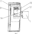
- the present disclosure further provides a refrigerator, including a door liner 9, an ice-making compartment 10, an ice-maker 11, an ice dispensing motor 12 and the ice-maker/ice storage box assembly described above.
- the ice-making compartment 10 is mounted on the door liner 9.
- the ice-maker 11 is mounted at an upper portion within the ice-making compartment 10.
- the ice dispensing motor 12 is mounted at a lower portion within the ice-making compartment 10.
- the ice storage box 1 is mounted in the ice-making compartment 10 and below the ice-maker 11.
- a motor shaft 13 of the ice dispensing motor 12 is provided vertical to the mounting surface of the ice dispensing motor 12 which may be an upper surface of the lower end of the ice-making compartment 10 or a side surface parallel to the door liner 9 in the ice-making compartment 10.
- the mounting surface of the ice dispensing motor 12 is the upper surface of the lower end of the ice-making compartment 10
- a mounting surface of the ice storage box 1 is a corresponding bottom surface of the ice storage box 1;
- the mounting surface of the ice dispensing motor 12 is the side surface parallel to the door liner 9 in the ice-making compartment 10
- the mounting surface of the ice storage box 1 is a corresponding side surface of the ice storage box 1.
- the motor shaft 13 may be provided vertical to the door liner 9 or parallel to the door liner 9.
- An end of the ice dispensing motor 12 is connected with a transmission connector 14 connected to the rotary-shaft connector 3 correspondingly.
- a lower end of the ice storage box 1 is positioned on the lower end of the ice-making compartment 10, so that other mounting and connecting members are not required and the mounted ice storage box 1 is stable and reliable.
- the ice storage box 1 needs to be removed, by separating the rotary-shaft connector 3 from the transmission connector 14 with the separation mechanism 7, the ice storage box 1 can be removed conveniently without damaging a connection portion between the ice dispensing motor 12 and the ice storage box 1.
- the ice storage box 1 can be removed in any direction without the limitation of the detaching directions.
- the mounted ice storage box 1 is not easy to fall off.
- the transmission connector 14 is mounted on the motor shaft 13 of the ice dispensing motor 12. Specifically, an end portion of the motor shaft 13 in axial direction may be provided with a threaded blind hole in which a bolt 15 is connected, and the transmission connector 14 is mounted on the motor shaft 13 through the bolt 15.
- the ice storage box 1 of the present disclosure can be removed conveniently without the limitation of the detaching direction. Further, the mounted ice storage box 1 is not easy to fall off and the mounting is reliable.
Landscapes
- Engineering & Computer Science (AREA)
- Physics & Mathematics (AREA)
- Mechanical Engineering (AREA)
- Thermal Sciences (AREA)
- General Engineering & Computer Science (AREA)
- Chemical & Material Sciences (AREA)
- Combustion & Propulsion (AREA)
- Production, Working, Storing, Or Distribution Of Ice (AREA)
- Refrigerator Housings (AREA)
- Devices That Are Associated With Refrigeration Equipment (AREA)
Abstract
Description
- The present disclosure relates to the technical field of refrigerator, and particularly to an ice-maker/ice storage box assembly and a refrigerator.
- At present, the detaching directions of an ice storage box mainly include the vertical direction and the horizontal direction. One of the detaching directions is, as disclosed in Patent No.
CN200910258882.0 - The technical problems to be solved by the present disclosure are how to facilitate the removing of the ice storage box without damaging the connection portion between the ice dispensing motor and the ice storage box; and how to remove the ice storage box without the limitation of a fixed direction.
- In order to solve the technical problems above, the present disclosure provides an ice-maker/ice storage box assembly including an ice storage box, which; wherein the ice storage box is provided with a rotary shaft and a separation mechanism; an outer end of the rotary shaft is provided with a rotary-shaft connector for connecting a transmission connector of a ice dispensing motor; the separation mechanism is configured to axially separate the transmission connector from the rotary-shaft connector.
- Wherein, the separation mechanism includes a pressing connecting arm, a pressing block and a fixing base shell; one end of the pressing connecting arm is arranged correspondingly to the rotary-shaft connector for moving the rotary-shaft connector along an axial direction of the rotary shaft; the pressing block is fixedly connected to the other end of the pressing connecting arm; the fixing base shell is fixed on the ice storage box, and the pressing block is connected to the fixing base shell.
- Wherein, one end of the rotary-shaft connector close to the ice storage box is provided with a blocking plate.
- Wherein, the rotary-shaft connector is connected to the blocking plate through a connecting sleeve; one end of the pressing connecting arm is arranged opposite to one side of the blocking plate, and there is a gap between the pressing connecting arm and the connecting sleeve.
- Wherein, an elastic resetting member is sleeved on the rotary shaft between the rotary-shaft connector and the ice storage box.
- Wherein, the elastic resetting member is a resetting spring.
- Wherein, an outer end of the rotary shaft is provided with an external thread, which is connected with a nut for preventing the rotary-shaft connector from shedding.
- Wherein, a limiting protrusion is provided on the pressing block, and a limiting slot corresponding to the limiting protrusion is provided on the fixing base shell.
- The present disclosure also provides a refrigerator, including a door liner, an ice-making compartment, an ice-maker, an ice dispensing motor and the ice-maker/ice storage box assembly above, the ice-making compartment being mounted on the door liner, the ice-maker being mounted at an upper portion within the ice-making compartment, the ice dispensing motor being mounted at a lower portion within the ice-making compartment; wherein the refrigerator further comprises the ice-maker/ice storage box assembly of any one of claims 1-8, and one end of the ice dispensing motor is connected with a transmission connector connected to the rotary-shaft connector, and a lower end of the ice storage box is positioned on a lower end of the ice-making compartment; when the ice storage box is removed, the rotary-shaft connector is separated from the transmission connector by the separation mechanism.
- Wherein, the transmission connector is mounted on a motor shaft of the ice dispensing motor.
- Compared to the prior art, the present disclosure has the following advantages:
The present disclosure provides an ice-maker/ice storage box assembly and a refrigerator, wherein the ice-maker/ice storage box assembly is improved on the basis of the structure of the existing ice storage box assembly. A rotary shaft and a separation mechanism are provided on the ice storage box, a rotary-shaft connector is provided at an outer end of the rotary shaft, the rotary-shaft connector is configured to be connected to a transmission connector of the ice dispensing motor; the separation mechanism is configured to axially separate the transmission connector from the rotary-shaft connector; when the ice storage box is required to be removed, the rotary-shaft connector is axially separated from the transmission connector by the separation mechanism, so that the ice storage box can be conveniently removed without damaging a connection portion between the ice dispensing motor and the ice storage box; after the rotary-shaft connector is separated from the transmission connector, the ice storage box can be removed in any direction without the limitation of the detaching directions. -
-
FIG.1 is a stereogram of an ice-maker/ice storage box assembly of the present disclosure; -
FIG.2 is a diagram of an ice-maker/ice storage box assembly of the present disclosure before it is assembled with an ice dispensing motor or after it is separated from the ice dispensing motor; -
FIG.3 is sectional view of a refrigerator (the rotary-shaft connector is connected to the transmission connector) of the present disclosure; -
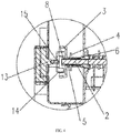
FIG.4 is a partial enlarged view of A inFIG.3 ; -
FIG.5 is sectional view of a refrigerator (the rotary-shaft connector is separated from the transmission connector) of the present disclosure; -
FIG.6 is a partial enlarged view of B inFIG.5 ; - In the drawings: 1: ice storage box; 2: rotary shaft; 3: rotary-shaft connector; 4: blocking plate; 5: connecting sleeve; 6: elastic resetting member; 7: separation mechanism; 71: pressing connecting arm; 72: pressing block; 73: fixing base shell; 74: limiting protrusion; 75: limiting slot; 8: nut; 9: door liner; 10: ice-making compartment; 11: ice-maker; 12: ice dispensing motor; 13: motor shaft; 14: transmission connector; 15: bolt.
- The specific implementation manners of the present disclosure will be further described in detail with reference to the accompanying drawings and embodiments. The following examples are used to illustrate the present disclosure, but are not intended to limit the scope thereof.
- It should be noted that, in the description of the present disclosure, the orientation or position relations indicated by the terms "center", "longitudinal", "lateral", "upper", "lower", "front", "rear", "left", "right", "vertical", "horizontal", "top", "bottom", "inner", "outer" etc. are relative to the operator. The side in front of the operator is "front", the side away from the operator is "rear", which is merely for the convenience of describing the present disclosure and simplifying the description, and is not to indicate or imply that the device or component referred to must have a specific orientation, and is constructed and operated in a specific orientation. Therefore it cannot be construed as limiting the present disclosure.
- In the description of the present disclosure, it should be noted that unless specifically defined or limited, the terms "mount", "connect to", and "connect with" should be understood in a broad sense, for example, they may be fixed connections or may be removable connections or integrated connections; may be mechanical connections or electrical connections; they may also be direct connections or indirect connections through intermediate medium, or may be internal communication between two components. For a person of ordinary skill in the art, the specific meanings of the terms above in the present disclosure can be understood according to specific situations.
- In addition, unless specified otherwise, "a plurality of' and "a plurality of sets" means two or more in the description of the present disclosure.
- As shown in
FIG.1-FIG.6 , the ice-maker/ice storage box assembly provided by the present disclosure includes anice storage box 1, wherein theice storage box 1 is provided with aseparation mechanism 7 and arotary shaft 2 vertical to a mounting surface of theice storage box 1. The mounting surface may be a side surface or a bottom surface of theice storage box 1. An end of therotary shaft 2 extends into theice storage box 1 and the other end of therotary shaft 2 extends out of theice storage box 1. The outer end of the rotary shaft 2 (i.e., therotary shaft 2 portion outside the ice storage box 1) is provided with a rotary-shaft connector 3 for connecting atransmission connector 14 of anice dispensing motor 12. Theseparation mechanism 7 is used to axially separate thetransmission connector 14 from the rotary-shaft connector 3, so that theice storage box 1 can be removed conveniently. In order to ensure a steady separation, theseparation mechanisms 7 can be symmetrically disposed on both sides of the rotary-shaft connector 3. - Specifically, as shown in
FIG.1 andFIG.4 , theseparation mechanism 7 may include a pressing connectingarm 71, apressing block 72 and afixing base shell 73. One end of the pressing connectingarm 71 is arranged correspondingly to the rotary-shaft connector 3 for moving the rotary-shaft connector 3 along an axial direction of therotary shaft 2, so as to axially separate thetransmission connector 14 from the rotary-shaft connector 3; alternatively, one end of the pressing connectingarm 71 may also be arranged correspondingly to thetransmission connector 14 for moving thetransmission connector 14 along an axial direction of theice dispensing motor 12, so as to axially separate thetransmission connector 14 from the rotary-shaft connector 3. Thepressing block 72 is fixedly connected to the other end of the pressing connectingarm 71, thefixing base shell 73 is fixed on theice storage box 1, and thepressing block 72 is connected to thefixing base shell 73. In order to facilitate the connection between the pressing connectingarm 71 and the rotary-shaft connector 3, one end of the rotary-shaft connector 3 close to theice storage box 1 is provided with ablocking plate 4 and the rotary-shaft connector 3 is connected to theblocking plate 4 through a connectingsleeve 5. One end of the pressing connectingarm 71 is arranged opposite to one side of the blockingplate 4, and there is a gap between the pressing connectingarm 71 and the connectingsleeve 5, so that it is convenient for pushing theblocking plate 4 by the pressing connectingarm 71 and the rotation of the rotary-shaft connector 3 will not be interfered. Of course, theblocking plate 4 and the connectingsleeve 5 may also be provided on thetransmission connector 14 in a same manner, one end of the pressing connectingarm 71 is arranged opposite to one side of theblocking plate 4, and there is a gap between the pressing connectingarm 71 and the connectingsleeve 5, so that it is convenient for pushing theblocking plate 4 by the pressing connectingarm 71 and the rotation of thetransmission connector 14 will not be interfered. Of course, theseparation mechanism 7 may also adopt other structures, as long as the rotary-shaft connector 3 can be separated from thetransmission connector 14. - As shown in
FIG.1 ,FIG.4 andFIG.6 , an elastic resettingmember 6, such as a resetting spring, may be sleeved on therotary shaft 2 between the rotary-shaft connector 3 and theice storage box 1, the elastic resettingmember 6 is arranged so that theseparation mechanism 7 and the rotary-shaft connector 3 can be reset. In addition, a blocking ring may also be provided at the junction between theice storage box 1 and therotary shaft 2. One end of the elastic resettingmember 6 is withstood by the blocking ring, so that the mounting surface is prevented from being worn due to the long-time use of the elastic resettingmember 6. Further, alimiting protrusion 74 may be provided on thepressing block 72, and alimiting slot 75 corresponding to the limitingprotrusion 74 is provided on thefixing base shell 73. When thepressing block 72 is pressed, thelimiting protrusion 74 is stuck in thelimiting slot 75 for positioning. Of course, an elastic member facilitating the returning may also be provided at the junction between thepressing block 72 and thefixing base shell 73. - Specifically, as shown in
FIG.4 , the outer end of therotary shaft 2 may be provided with an external thread, which is connected with anut 8 for preventing the rotary-shaft connector 3 from shedding, the rotary-shaft connector 3 is limited by thenut 8. Of course, therotary shaft 2 may also be provided without the external thread, instead, thenut 8 or other limiting members are directly welded at the outer end of therotary shaft 2. - Preferably, as shown in
FIG.1 , the pressing connectingarm 71 is in an L-shape and a corner of the pressing connectingarm 71 is provided with a transitional cambered surface. The corner of the pressing connectingarm 71 corresponds to a corner of theice storage box 1, so that the structure is compact. - As shown in
FIG.1-FIG.6 , the present disclosure further provides a refrigerator, including adoor liner 9, an ice-makingcompartment 10, an ice-maker 11, anice dispensing motor 12 and the ice-maker/ice storage box assembly described above. The ice-makingcompartment 10 is mounted on thedoor liner 9. The ice-maker 11 is mounted at an upper portion within the ice-makingcompartment 10. Theice dispensing motor 12 is mounted at a lower portion within the ice-makingcompartment 10. Theice storage box 1 is mounted in the ice-makingcompartment 10 and below the ice-maker 11. Amotor shaft 13 of theice dispensing motor 12 is provided vertical to the mounting surface of theice dispensing motor 12 which may be an upper surface of the lower end of the ice-makingcompartment 10 or a side surface parallel to thedoor liner 9 in the ice-makingcompartment 10. When the mounting surface of theice dispensing motor 12 is the upper surface of the lower end of the ice-makingcompartment 10, a mounting surface of theice storage box 1 is a corresponding bottom surface of theice storage box 1; when the mounting surface of theice dispensing motor 12 is the side surface parallel to thedoor liner 9 in the ice-makingcompartment 10, the mounting surface of theice storage box 1 is a corresponding side surface of theice storage box 1. That is, themotor shaft 13 may be provided vertical to thedoor liner 9 or parallel to thedoor liner 9. An end of theice dispensing motor 12 is connected with atransmission connector 14 connected to the rotary-shaft connector 3 correspondingly. A lower end of theice storage box 1 is positioned on the lower end of the ice-makingcompartment 10, so that other mounting and connecting members are not required and the mountedice storage box 1 is stable and reliable. When theice storage box 1 needs to be removed, by separating the rotary-shaft connector 3 from thetransmission connector 14 with theseparation mechanism 7, theice storage box 1 can be removed conveniently without damaging a connection portion between theice dispensing motor 12 and theice storage box 1. After the rotary-shaft connector 3 is separated from thetransmission connector 14, theice storage box 1 can be removed in any direction without the limitation of the detaching directions. Moreover, the mountedice storage box 1 is not easy to fall off. - In order to facilitating the mounting of the
transmission connector 14, thetransmission connector 14 is mounted on themotor shaft 13 of theice dispensing motor 12. Specifically, an end portion of themotor shaft 13 in axial direction may be provided with a threaded blind hole in which abolt 15 is connected, and thetransmission connector 14 is mounted on themotor shaft 13 through thebolt 15. - It can be seen from the embodiments above that, the
ice storage box 1 of the present disclosure can be removed conveniently without the limitation of the detaching direction. Further, the mountedice storage box 1 is not easy to fall off and the mounting is reliable. - The above are only preferred embodiments of the present disclosure, and are not intended to limit the present disclosure. Any modifications, equivalent replacements and improvements made within the spirit and principle of the present application shall be within the protection scope of the present application.
Claims (10)
- An ice-maker/ice storage box assembly, characterized in comprising an ice storage box; wherein the ice storage box is provided with a rotary shaft and a separation mechanism; an outer end of the rotary shaft is provided with a rotary-shaft connector for connecting a transmission connector of a ice dispensing motor; the separation mechanism is configured to axially separate the transmission connector from the rotary-shaft connector.
- The ice-maker/ice storage box assembly of claim 1, characterized in that the separation mechanism comprises a pressing connecting arm, a pressing block and a fixing base shell; one end of the pressing connecting arm is arranged correspondingly to the rotary-shaft connector for moving the rotary-shaft connector along an axial direction of the rotary shaft; the pressing block is fixedly connected to the other end of the pressing connecting arm; the fixing base shell is fixed on the ice storage box and the pressing block is connected to the fixing base shell.
- The ice-maker/ice storage box assembly of claim 2, characterized in that one end of the rotary-shaft connector close to the ice storage box is provided with a blocking plate.
- The ice-maker/ice storage box assembly of claim 3, characterized in that the rotary-shaft connector is connected to the blocking plate through a connecting sleeve; one end of the pressing connecting arm is arranged opposite to one side of the blocking plate, and there is a gap between the pressing connecting arm and the connecting sleeve.
- The ice-maker/ice storage box assembly of claim 1, characterized in that an elastic resetting member is sleeved on the rotary shaft between the rotary-shaft connector and the ice storage box.
- The ice-maker/ice storage box assembly of claim 5, characterized in that the elastic resetting member is a resetting spring.
- The ice-maker/ice storage box assembly of claim 1, characterized in that an outer end of the rotary shaft is provided with an external thread which is connected with a nut for preventing the rotary-shaft connector from shedding.
- The ice-maker/ice storage box assembly of claim 2, characterized in that a limiting protrusion is provided on the pressing block, and a limiting slot corresponding to the limiting protrusion is provided on the fixing base shell.
- A refrigerator, characterized in comprising a door liner, an ice-making compartment, an ice-maker and an ice dispensing motor, the ice-making compartment being mounted on the door liner, the ice-maker being mounted at an upper portion within the ice-making compartment, the ice dispensing motor being mounted at a lower portion within the ice-making compartment; wherein the refrigerator further comprises the ice-maker/ice storage box assembly of any one of claims 1-8, and one end of the ice dispensing motor is connected with a transmission connector connected to the rotary-shaft connector, and a lower end of the ice storage box is positioned on a lower end of the ice-making compartment; when the ice storage box is removed, the rotary-shaft connector is separated from the transmission connector by the separation mechanism.
- The refrigerator of claim 9, characterized in that the transmission connector is mounted on a motor shaft of the ice dispensing motor.
Applications Claiming Priority (2)
| Application Number | Priority Date | Filing Date | Title |
|---|---|---|---|
| CN201610383789.2A CN106016880B (en) | 2016-05-27 | 2016-05-27 | A kind of ice storing box of ice-maker component and refrigerator |
| PCT/CN2016/087286 WO2017201798A1 (en) | 2016-05-27 | 2016-06-27 | Ice-maker/ice storage box assembly and refrigerator |
Publications (3)
| Publication Number | Publication Date |
|---|---|
| EP3450885A1 true EP3450885A1 (en) | 2019-03-06 |
| EP3450885A4 EP3450885A4 (en) | 2019-05-08 |
| EP3450885B1 EP3450885B1 (en) | 2020-04-15 |
Family
ID=57089307
Family Applications (1)
| Application Number | Title | Priority Date | Filing Date |
|---|---|---|---|
| EP16902786.9A Active EP3450885B1 (en) | 2016-05-27 | 2016-06-27 | Ice-maker and ice storage box assembly and refrigerator |
Country Status (4)
| Country | Link |
|---|---|
| US (1) | US10808980B2 (en) |
| EP (1) | EP3450885B1 (en) |
| CN (1) | CN106016880B (en) |
| WO (1) | WO2017201798A1 (en) |
Families Citing this family (6)
| Publication number | Priority date | Publication date | Assignee | Title |
|---|---|---|---|---|
| CN106247716A (en) * | 2016-10-21 | 2016-12-21 | 合肥华凌股份有限公司 | Refrigerator and ice machine assembly thereof |
| US10775088B2 (en) * | 2018-02-16 | 2020-09-15 | Haier Us Appliance Solutions, Inc. | Ice making assembly coupling |
| CN109708346B (en) * | 2018-09-28 | 2021-08-24 | 海尔智家股份有限公司 | Door ice-making device and refrigerator having the same |
| US11262116B2 (en) * | 2019-05-03 | 2022-03-01 | Haier Us Appliance Solutions, Inc. | Refrigerator appliance having a removable ice storage bin |
| CN113091384B (en) * | 2020-01-07 | 2022-10-28 | 青岛海尔电冰箱有限公司 | Ice storage box assembly of ice maker and refrigerator |
| CN111829234B (en) * | 2020-06-18 | 2021-12-03 | 广东格兰仕集团有限公司 | Ice crushing transmission device of ice maker of refrigerator |
Family Cites Families (11)
| Publication number | Priority date | Publication date | Assignee | Title |
|---|---|---|---|---|
| US6442954B1 (en) * | 2001-07-02 | 2002-09-03 | General Electric Company | Dual hopper icemaking refrigerator |
| EP2235450B1 (en) * | 2007-12-14 | 2024-04-03 | Lg Electronics, Inc. | Refrigerator with an ice bank |
| KR101565410B1 (en) * | 2009-06-24 | 2015-11-03 | 엘지전자 주식회사 | Ice bank assembly |
| KR101632213B1 (en) * | 2009-10-08 | 2016-06-21 | 엘지전자 주식회사 | A refrigerator and an ice bank |
| KR101907166B1 (en) * | 2011-12-30 | 2018-10-15 | 삼성전자주식회사 | Refrigerator |
| CN102661645B (en) * | 2012-05-14 | 2014-08-13 | 湖北美的电冰箱有限公司 | Refrigerator, ice storage box and ice outlet connecting piece |
| WO2013183890A1 (en) * | 2012-06-07 | 2013-12-12 | Samsung Electronics Co., Ltd. | Refrigerator |
| KR101969588B1 (en) * | 2012-06-20 | 2019-04-16 | 엘지전자 주식회사 | A rerigerator including an ice container |
| KR102135973B1 (en) * | 2013-04-02 | 2020-07-21 | 삼성전자주식회사 | Refrigerator |
| CN104006595B (en) * | 2014-05-20 | 2016-06-29 | 海信容声(广东)冰箱有限公司 | A kind of refrigerator ice storage box assembly and with its refrigerator |
| KR101798550B1 (en) * | 2016-04-12 | 2017-11-17 | 동부대우전자 주식회사 | Ice bin and refrigerator having the ice bin |
-
2016
- 2016-05-27 CN CN201610383789.2A patent/CN106016880B/en active Active
- 2016-06-27 EP EP16902786.9A patent/EP3450885B1/en active Active
- 2016-06-27 WO PCT/CN2016/087286 patent/WO2017201798A1/en not_active Ceased
-
2018
- 2018-11-26 US US16/200,232 patent/US10808980B2/en not_active Expired - Fee Related
Also Published As
| Publication number | Publication date |
|---|---|
| CN106016880A (en) | 2016-10-12 |
| WO2017201798A1 (en) | 2017-11-30 |
| US20190145687A1 (en) | 2019-05-16 |
| CN106016880B (en) | 2018-09-14 |
| EP3450885A4 (en) | 2019-05-08 |
| EP3450885B1 (en) | 2020-04-15 |
| US10808980B2 (en) | 2020-10-20 |
Similar Documents
| Publication | Publication Date | Title |
|---|---|---|
| US10808980B2 (en) | Ice-maker/ice storage box assembly and refrigerator | |
| CN209403052U (en) | Intelligent grass-removing | |
| CN203434662U (en) | Charging cabinet | |
| US20240008541A1 (en) | Electronic heating device | |
| CN213393002U (en) | Display screen unit and splicing type display screen | |
| US12439545B2 (en) | Supercomputing server | |
| US7163240B2 (en) | Vehicle door handle device | |
| CN108206361B (en) | Connector module | |
| CN217133417U (en) | Optical fiber aviation plug-in limiting device | |
| US10483063B1 (en) | Protective relay with easy withdrawal | |
| CN112164151A (en) | An anti-demolition self-destruction device and a vehicle-mounted unit applied to a vehicle-mounted unit | |
| CN213275739U (en) | Electronic voltage sensor | |
| CN217382245U (en) | Front maintenance magnetic anti-drop mechanism for LED display screen | |
| CN214848447U (en) | Circuit breaker | |
| CN213987578U (en) | Anti-dismantling self-destruction device applied to vehicle-mounted unit and vehicle-mounted unit | |
| CN211929768U (en) | Convenient 37-core socket who overhauls | |
| CN210925904U (en) | A circuit breaker for rail vehicle running control | |
| CN219995010U (en) | Security protection monitoring device convenient to installation | |
| CN113993330B (en) | Railway lighting fixture drive control device based on PA6T material | |
| CN212874740U (en) | 5G unmanned aerial vehicle antenna mounting base | |
| CN221407106U (en) | Micro-switch | |
| CN208077896U (en) | Earth leakage circuit breaker | |
| CN210779268U (en) | Portable push-pull type module box structure | |
| CN205959888U (en) | Electromagnetic switch end cover, starter motor electromagnetic switch and relay end cover | |
| CN212389156U (en) | Unlocking mechanism of computer key and computer key with unlocking mechanism |
Legal Events
| Date | Code | Title | Description |
|---|---|---|---|
| STAA | Information on the status of an ep patent application or granted ep patent |
Free format text: STATUS: THE INTERNATIONAL PUBLICATION HAS BEEN MADE |
|
| PUAI | Public reference made under article 153(3) epc to a published international application that has entered the european phase |
Free format text: ORIGINAL CODE: 0009012 |
|
| STAA | Information on the status of an ep patent application or granted ep patent |
Free format text: STATUS: REQUEST FOR EXAMINATION WAS MADE |
|
| 17P | Request for examination filed |
Effective date: 20181127 |
|
| AK | Designated contracting states |
Kind code of ref document: A1 Designated state(s): AL AT BE BG CH CY CZ DE DK EE ES FI FR GB GR HR HU IE IS IT LI LT LU LV MC MK MT NL NO PL PT RO RS SE SI SK SM TR |
|
| AX | Request for extension of the european patent |
Extension state: BA ME |
|
| A4 | Supplementary search report drawn up and despatched |
Effective date: 20190410 |
|
| RIC1 | Information provided on ipc code assigned before grant |
Ipc: F25C 5/18 20180101AFI20190404BHEP Ipc: F25C 5/20 20180101ALI20190404BHEP |
|
| DAV | Request for validation of the european patent (deleted) | ||
| DAX | Request for extension of the european patent (deleted) | ||
| GRAP | Despatch of communication of intention to grant a patent |
Free format text: ORIGINAL CODE: EPIDOSNIGR1 |
|
| STAA | Information on the status of an ep patent application or granted ep patent |
Free format text: STATUS: GRANT OF PATENT IS INTENDED |
|
| INTG | Intention to grant announced |
Effective date: 20191111 |
|
| GRAS | Grant fee paid |
Free format text: ORIGINAL CODE: EPIDOSNIGR3 |
|
| GRAA | (expected) grant |
Free format text: ORIGINAL CODE: 0009210 |
|
| STAA | Information on the status of an ep patent application or granted ep patent |
Free format text: STATUS: THE PATENT HAS BEEN GRANTED |
|
| AK | Designated contracting states |
Kind code of ref document: B1 Designated state(s): AL AT BE BG CH CY CZ DE DK EE ES FI FR GB GR HR HU IE IS IT LI LT LU LV MC MK MT NL NO PL PT RO RS SE SI SK SM TR |
|
| REG | Reference to a national code |
Ref country code: CH Ref legal event code: EP |
|
| REG | Reference to a national code |
Ref country code: DE Ref legal event code: R096 Ref document number: 602016034318 Country of ref document: DE |
|
| REG | Reference to a national code |
Ref country code: IE Ref legal event code: FG4D |
|
| REG | Reference to a national code |
Ref country code: AT Ref legal event code: REF Ref document number: 1257789 Country of ref document: AT Kind code of ref document: T Effective date: 20200515 |
|
| REG | Reference to a national code |
Ref country code: NL Ref legal event code: MP Effective date: 20200415 |
|
| REG | Reference to a national code |
Ref country code: LT Ref legal event code: MG4D |
|
| PG25 | Lapsed in a contracting state [announced via postgrant information from national office to epo] |
Ref country code: SE Free format text: LAPSE BECAUSE OF FAILURE TO SUBMIT A TRANSLATION OF THE DESCRIPTION OR TO PAY THE FEE WITHIN THE PRESCRIBED TIME-LIMIT Effective date: 20200415 Ref country code: NL Free format text: LAPSE BECAUSE OF FAILURE TO SUBMIT A TRANSLATION OF THE DESCRIPTION OR TO PAY THE FEE WITHIN THE PRESCRIBED TIME-LIMIT Effective date: 20200415 Ref country code: GR Free format text: LAPSE BECAUSE OF FAILURE TO SUBMIT A TRANSLATION OF THE DESCRIPTION OR TO PAY THE FEE WITHIN THE PRESCRIBED TIME-LIMIT Effective date: 20200716 Ref country code: NO Free format text: LAPSE BECAUSE OF FAILURE TO SUBMIT A TRANSLATION OF THE DESCRIPTION OR TO PAY THE FEE WITHIN THE PRESCRIBED TIME-LIMIT Effective date: 20200715 Ref country code: FI Free format text: LAPSE BECAUSE OF FAILURE TO SUBMIT A TRANSLATION OF THE DESCRIPTION OR TO PAY THE FEE WITHIN THE PRESCRIBED TIME-LIMIT Effective date: 20200415 Ref country code: PT Free format text: LAPSE BECAUSE OF FAILURE TO SUBMIT A TRANSLATION OF THE DESCRIPTION OR TO PAY THE FEE WITHIN THE PRESCRIBED TIME-LIMIT Effective date: 20200817 Ref country code: IS Free format text: LAPSE BECAUSE OF FAILURE TO SUBMIT A TRANSLATION OF THE DESCRIPTION OR TO PAY THE FEE WITHIN THE PRESCRIBED TIME-LIMIT Effective date: 20200815 Ref country code: LT Free format text: LAPSE BECAUSE OF FAILURE TO SUBMIT A TRANSLATION OF THE DESCRIPTION OR TO PAY THE FEE WITHIN THE PRESCRIBED TIME-LIMIT Effective date: 20200415 |
|
| REG | Reference to a national code |
Ref country code: AT Ref legal event code: MK05 Ref document number: 1257789 Country of ref document: AT Kind code of ref document: T Effective date: 20200415 |
|
| PG25 | Lapsed in a contracting state [announced via postgrant information from national office to epo] |
Ref country code: BG Free format text: LAPSE BECAUSE OF FAILURE TO SUBMIT A TRANSLATION OF THE DESCRIPTION OR TO PAY THE FEE WITHIN THE PRESCRIBED TIME-LIMIT Effective date: 20200715 Ref country code: RS Free format text: LAPSE BECAUSE OF FAILURE TO SUBMIT A TRANSLATION OF THE DESCRIPTION OR TO PAY THE FEE WITHIN THE PRESCRIBED TIME-LIMIT Effective date: 20200415 Ref country code: LV Free format text: LAPSE BECAUSE OF FAILURE TO SUBMIT A TRANSLATION OF THE DESCRIPTION OR TO PAY THE FEE WITHIN THE PRESCRIBED TIME-LIMIT Effective date: 20200415 Ref country code: HR Free format text: LAPSE BECAUSE OF FAILURE TO SUBMIT A TRANSLATION OF THE DESCRIPTION OR TO PAY THE FEE WITHIN THE PRESCRIBED TIME-LIMIT Effective date: 20200415 |
|
| PG25 | Lapsed in a contracting state [announced via postgrant information from national office to epo] |
Ref country code: AL Free format text: LAPSE BECAUSE OF FAILURE TO SUBMIT A TRANSLATION OF THE DESCRIPTION OR TO PAY THE FEE WITHIN THE PRESCRIBED TIME-LIMIT Effective date: 20200415 |
|
| REG | Reference to a national code |
Ref country code: DE Ref legal event code: R097 Ref document number: 602016034318 Country of ref document: DE |
|
| PG25 | Lapsed in a contracting state [announced via postgrant information from national office to epo] |
Ref country code: RO Free format text: LAPSE BECAUSE OF FAILURE TO SUBMIT A TRANSLATION OF THE DESCRIPTION OR TO PAY THE FEE WITHIN THE PRESCRIBED TIME-LIMIT Effective date: 20200415 Ref country code: CZ Free format text: LAPSE BECAUSE OF FAILURE TO SUBMIT A TRANSLATION OF THE DESCRIPTION OR TO PAY THE FEE WITHIN THE PRESCRIBED TIME-LIMIT Effective date: 20200415 Ref country code: DK Free format text: LAPSE BECAUSE OF FAILURE TO SUBMIT A TRANSLATION OF THE DESCRIPTION OR TO PAY THE FEE WITHIN THE PRESCRIBED TIME-LIMIT Effective date: 20200415 Ref country code: IT Free format text: LAPSE BECAUSE OF FAILURE TO SUBMIT A TRANSLATION OF THE DESCRIPTION OR TO PAY THE FEE WITHIN THE PRESCRIBED TIME-LIMIT Effective date: 20200415 Ref country code: SM Free format text: LAPSE BECAUSE OF FAILURE TO SUBMIT A TRANSLATION OF THE DESCRIPTION OR TO PAY THE FEE WITHIN THE PRESCRIBED TIME-LIMIT Effective date: 20200415 Ref country code: EE Free format text: LAPSE BECAUSE OF FAILURE TO SUBMIT A TRANSLATION OF THE DESCRIPTION OR TO PAY THE FEE WITHIN THE PRESCRIBED TIME-LIMIT Effective date: 20200415 Ref country code: AT Free format text: LAPSE BECAUSE OF FAILURE TO SUBMIT A TRANSLATION OF THE DESCRIPTION OR TO PAY THE FEE WITHIN THE PRESCRIBED TIME-LIMIT Effective date: 20200415 Ref country code: MC Free format text: LAPSE BECAUSE OF FAILURE TO SUBMIT A TRANSLATION OF THE DESCRIPTION OR TO PAY THE FEE WITHIN THE PRESCRIBED TIME-LIMIT Effective date: 20200415 Ref country code: ES Free format text: LAPSE BECAUSE OF FAILURE TO SUBMIT A TRANSLATION OF THE DESCRIPTION OR TO PAY THE FEE WITHIN THE PRESCRIBED TIME-LIMIT Effective date: 20200415 |
|
| REG | Reference to a national code |
Ref country code: CH Ref legal event code: PL |
|
| PLBE | No opposition filed within time limit |
Free format text: ORIGINAL CODE: 0009261 |
|
| STAA | Information on the status of an ep patent application or granted ep patent |
Free format text: STATUS: NO OPPOSITION FILED WITHIN TIME LIMIT |
|
| PG25 | Lapsed in a contracting state [announced via postgrant information from national office to epo] |
Ref country code: PL Free format text: LAPSE BECAUSE OF FAILURE TO SUBMIT A TRANSLATION OF THE DESCRIPTION OR TO PAY THE FEE WITHIN THE PRESCRIBED TIME-LIMIT Effective date: 20200415 Ref country code: SK Free format text: LAPSE BECAUSE OF FAILURE TO SUBMIT A TRANSLATION OF THE DESCRIPTION OR TO PAY THE FEE WITHIN THE PRESCRIBED TIME-LIMIT Effective date: 20200415 |
|
| 26N | No opposition filed |
Effective date: 20210118 |
|
| PG25 | Lapsed in a contracting state [announced via postgrant information from national office to epo] |
Ref country code: LU Free format text: LAPSE BECAUSE OF NON-PAYMENT OF DUE FEES Effective date: 20200627 |
|
| REG | Reference to a national code |
Ref country code: BE Ref legal event code: MM Effective date: 20200630 |
|
| PG25 | Lapsed in a contracting state [announced via postgrant information from national office to epo] |
Ref country code: CH Free format text: LAPSE BECAUSE OF NON-PAYMENT OF DUE FEES Effective date: 20200630 Ref country code: LI Free format text: LAPSE BECAUSE OF NON-PAYMENT OF DUE FEES Effective date: 20200630 |
|
| PG25 | Lapsed in a contracting state [announced via postgrant information from national office to epo] |
Ref country code: BE Free format text: LAPSE BECAUSE OF NON-PAYMENT OF DUE FEES Effective date: 20200630 Ref country code: SI Free format text: LAPSE BECAUSE OF FAILURE TO SUBMIT A TRANSLATION OF THE DESCRIPTION OR TO PAY THE FEE WITHIN THE PRESCRIBED TIME-LIMIT Effective date: 20200415 |
|
| PG25 | Lapsed in a contracting state [announced via postgrant information from national office to epo] |
Ref country code: TR Free format text: LAPSE BECAUSE OF FAILURE TO SUBMIT A TRANSLATION OF THE DESCRIPTION OR TO PAY THE FEE WITHIN THE PRESCRIBED TIME-LIMIT Effective date: 20200415 Ref country code: MT Free format text: LAPSE BECAUSE OF FAILURE TO SUBMIT A TRANSLATION OF THE DESCRIPTION OR TO PAY THE FEE WITHIN THE PRESCRIBED TIME-LIMIT Effective date: 20200415 Ref country code: CY Free format text: LAPSE BECAUSE OF FAILURE TO SUBMIT A TRANSLATION OF THE DESCRIPTION OR TO PAY THE FEE WITHIN THE PRESCRIBED TIME-LIMIT Effective date: 20200415 |
|
| PG25 | Lapsed in a contracting state [announced via postgrant information from national office to epo] |
Ref country code: MK Free format text: LAPSE BECAUSE OF FAILURE TO SUBMIT A TRANSLATION OF THE DESCRIPTION OR TO PAY THE FEE WITHIN THE PRESCRIBED TIME-LIMIT Effective date: 20200415 |
|
| PGFP | Annual fee paid to national office [announced via postgrant information from national office to epo] |
Ref country code: IE Payment date: 20230626 Year of fee payment: 8 Ref country code: FR Payment date: 20230626 Year of fee payment: 8 Ref country code: DE Payment date: 20230628 Year of fee payment: 8 |
|
| PGFP | Annual fee paid to national office [announced via postgrant information from national office to epo] |
Ref country code: GB Payment date: 20230626 Year of fee payment: 8 |
|
| REG | Reference to a national code |
Ref country code: DE Ref legal event code: R119 Ref document number: 602016034318 Country of ref document: DE |
|
| GBPC | Gb: european patent ceased through non-payment of renewal fee |
Effective date: 20240627 |
|
| PG25 | Lapsed in a contracting state [announced via postgrant information from national office to epo] |
Ref country code: DE Free format text: LAPSE BECAUSE OF NON-PAYMENT OF DUE FEES Effective date: 20250101 |
|
| PG25 | Lapsed in a contracting state [announced via postgrant information from national office to epo] |
Ref country code: IE Free format text: LAPSE BECAUSE OF NON-PAYMENT OF DUE FEES Effective date: 20240627 |
|
| PG25 | Lapsed in a contracting state [announced via postgrant information from national office to epo] |
Ref country code: FR Free format text: LAPSE BECAUSE OF NON-PAYMENT OF DUE FEES Effective date: 20240630 |
|
| PG25 | Lapsed in a contracting state [announced via postgrant information from national office to epo] |
Ref country code: GB Free format text: LAPSE BECAUSE OF NON-PAYMENT OF DUE FEES Effective date: 20240627 |