EP3450857A2 - A white good and operation method - Google Patents
A white good and operation method Download PDFInfo
- Publication number
- EP3450857A2 EP3450857A2 EP18186460.4A EP18186460A EP3450857A2 EP 3450857 A2 EP3450857 A2 EP 3450857A2 EP 18186460 A EP18186460 A EP 18186460A EP 3450857 A2 EP3450857 A2 EP 3450857A2
- Authority
- EP
- European Patent Office
- Prior art keywords
- flap
- door
- gear
- movement
- connection
- Prior art date
- Legal status (The legal status is an assumption and is not a legal conclusion. Google has not performed a legal analysis and makes no representation as to the accuracy of the status listed.)
- Granted
Links
Images



Classifications
-
- F—MECHANICAL ENGINEERING; LIGHTING; HEATING; WEAPONS; BLASTING
- F24—HEATING; RANGES; VENTILATING
- F24C—DOMESTIC STOVES OR RANGES ; DETAILS OF DOMESTIC STOVES OR RANGES, OF GENERAL APPLICATION
- F24C15/00—Details
- F24C15/02—Doors specially adapted for stoves or ranges
- F24C15/025—Doors specially adapted for stoves or ranges with air curtain closures
-
- F—MECHANICAL ENGINEERING; LIGHTING; HEATING; WEAPONS; BLASTING
- F24—HEATING; RANGES; VENTILATING
- F24C—DOMESTIC STOVES OR RANGES ; DETAILS OF DOMESTIC STOVES OR RANGES, OF GENERAL APPLICATION
- F24C15/00—Details
- F24C15/006—Arrangements for circulation of cooling air
-
- F—MECHANICAL ENGINEERING; LIGHTING; HEATING; WEAPONS; BLASTING
- F24—HEATING; RANGES; VENTILATING
- F24C—DOMESTIC STOVES OR RANGES ; DETAILS OF DOMESTIC STOVES OR RANGES, OF GENERAL APPLICATION
- F24C15/00—Details
- F24C15/02—Doors specially adapted for stoves or ranges
Definitions
- Present invention relates to white goods, such as ovens, in which a certain temperature value should be maintained during operation, and to operation methods of these white goods.
- a certain temperature value should be maintained in a compartment comprised therein.
- this high temperature value may damage components provided in the control panel where operation of the white good is arranged.
- a fan is utilised which provides to circulate outer environment air, having lower temperature than the temperature within the compartment, in a channel to cool said components.
- high temperature value within the compartment does not merely affect said components.
- the patent document no. US3387600A discloses an air curtain means obtained by blowing air through the side walls of an oven.
- the oven disclosed in said document comprises a fan provided at a bottom side of the cooking compartment; holes provided at a side edge of the compartment; a flexible hose which allows the outer environment air drawn by the fan to reach to the holes; and a sensor which senses that the door is opened.
- the sensor senses when the door is opened, and the fan is enabled to operate.
- the fan operates, the outer environment air is transmitted to the holes through the hose, and is reached to door opening through the holes so as to form an air curtain in front of the compartment.
- a white good developed with the present invention comprises at least one body; at least one compartment which is located in the body, which has a temperature higher than the outer environment temperature during the operation, which is surrounded by at least one first side, at least one second side opposite to the first side, and at least one third side located between the first side and the second side such that it connects a part of the first side with a part of the second side being opposed to said part of the first side, and which comprises at least one opening for access to inside; at least one control panel which is provided at the body, at a part of the first side which does not face the compartment, and which arranges the operation of the white good; at least one door which controls the access to the opening, which has a closed position to prevent access to the opening and an opened position to allow access to the opening, which is able to move for transition between these opened/closed positions, which comprises at least one fourth side which approaches to and move away from the first side during this movement, wherein at least one cavity, being in connection with the outer environment, is formed between the control panel and the door when
- the air directed to the outer environment by the fan which enables to cool the components that are already provided at the white good and located at the control panel, forms an air curtain between the opening and the door by being directed to the compartment opening when the door is in the closed position; therefore objects around the white good can be prevented to be negatively affected by the air and gases of high temperature which are released from the compartment to the outer environment when the door is opened, and thus, a white good is obtained which is cheap, easy and practical to produce.
- Object of the present invention is to develop a white good in which the air within the compartment, which reaches to a high temperature value during the operation, is prevented from producing a negative effect when the door is opened, and an operation method for this white good.
- Another object of the present invention is to develop a white good which is prevented from producing a negative effect when the door is closed, as well as being prevented from producing a negative effect when the door is opened, and an operation method for this white good.
- Another object of the present invention is to develop a white good for which the operation efficacy and efficiency is increased, and an operation method for this white good.
- Another object of the present invention is to develop a white good which is cheap, easy and practical to produce, and an operation method for this white good.
- a compartment comprised within the white good should have a high temperature during operation.
- this high temperature negatively affects the components located in the control panel where operation of the white good is arranged, and therefore the white good may be prevented to operate at a required efficacy.
- a fan (M) is provided, and the fan (M) makes the outer environment air, having a temperature lower than the compartment (B), pass through a channel (H) which is in thermal interaction with the control panel (P) such that the components are prevented from being affected by the high temperature.
- the air which is passed through the channel (K) and heated due to high temperature within the compartment (B), is transmitted to the outer environment through a cavity located between the door (D) and the control panel (P).
- this high temperature together with various gases formed in the compartment due to the high temperature, especially when the door of the white good is opened, may negatively affect the user and/or the furniture being close to the white good as well as said components.
- a white good which prevents both the components in the control panel, the door, and the objects around the white good when the door is opened, from being negatively affected by the high temperature within the compartment and, an operation method for this white good.
- the white good (A) developed with the present invention comprises at least one body (G); at least one compartment (B) which is located in the body (G), which has a temperature higher than the outer environment temperature during the operation of the white good (A), which is surrounded by at least one first side (B1) (preferably top side or ceiling), at least one second side (B2) opposite to the first side (B1) (preferably bottom side or base), and at least one third side located between the first side (B1) and the second side (B2) such that it connects a part of the first side (B1) with a part of the second side (B2) being opposed to said part of the first side (B1), and which comprises at least one opening (B4) for access to inside that is preferably provided opposite to the third side (B3); at least one control panel (P) which is provided at the body (G), at a part of the first side (B1) which does not face the compartment (B) (preferably at a top part of the first side), and which arranges the operation
- the developed white good (A) also comprising at least one flap arrangement (K), exemplary embodiments of which are illustrated in figure 4 and figure 8 to figure 12 , which comprises: at least one first hinge (K2) (preferably at least two); at least one first flap (K1) which has a plate structure extending parallel to the first side (B1), which is in connection with the first hinge (K2) so as to be able to move by rotating around an axis via at least one torsion spring preferably located at the first hinge (K2), which has a first position that allows the air, reaching to the cavity through the channel (H), to pass to the outer environment when the door (D) is in closed position, and a second position that enables the air reaching to the cavity to be directed, preferably in parallel with the opening (B4) or vertically to the second side (B2), towards the opening (B4) (and therefore towards the second side (B2)) by posing an obstacle to the connection of the cavity with
- the temperature within the compartment (B) reaches to a higher temperature than the outer environment within which the white good (A) is present. For that reason, in order not to affect the control panel (P) which arranges the operation of the white good (A) by the high temperature at the compartment (B), when the white good (A) starts to operate, the fan (M) also starts to operate. When the fan (M) operates, the outer environment air is drawn through the hole provided at the body (G) such that it is directed to the channel (H) through the inlet opening.
- the channel (H) Due to the fact that the channel (H) is in thermal connection with the control panel (P), the outer environment air circulating in the channel (H) both prevents control panel (P) from being affected by the temperature in the compartment (B), and cools the control panel (P). In the meantime, because of the fact that the door (D) is closed, the first flap (K1) is in the first position, and therefore the cavity is in connection with the outer environment. By this way, the air circulating through the channel (H) reaches to the cavity to pass to the outer environment.
- the first flap (K1) rotates around the axis, passing through the region where it is in connection with the first hinge (K2), by moving such that its free side which is not in connection with the first hinge (K2) moves away from the first hinge (K2), and takes place in the second position in which the first flap (K1) is inclined with respect to the first side (B1), by this way, pose an obstacle to the connection of the cavity with the outer environment, and enables the air, which reaches from the channel (H) to the cavity, to be directed to the opening (B4) and therefore to the second side (B2) other than the outer environment.
- an air curtain is formed between the opening (B4) and the door (D), and the air inside the compartment (B) is prevented from escaping directly to the outer environment such that the user, objects like furniture that are present around the white good (A) are able to be prevented from being negatively affected by the hot air and gases inside the compartment (B).
- a white good (A) is obtained which is cheap, easy and practical to produce.
- the fan (M) has at least one second operating speed (e.g. within the range of 1200-1500 revolutions per minute) higher than the first operating speed
- the developed white good (A) preferably comprises at least one first sensor (K3) which, by sensing movement of the first flap (K1), enables to operate the fan (M) at the first operating speed if the first flap (K1) is in the first position and to operate the fan (M) at the second operating speed if the first flap (K1) is in the second position, and which accordingly controls the operating speed of the fan (M).
- the first sensor (K3) may preferably be a mechanical switch, an ultrasonic sensor, a laser sensor, an inductive sensor, a light sensor or a capacitive sensor.
- Operating time change of the fan (M) can be performed mechanically by the first sensor (K3), or by a control unit comprised within the white good (A) such that the control unit processes the signals received from the first sensor (K3).
- the movement equipment preferably comprises at least one first protrusion (K4) provided at the surface of the first flap (K1) that faces the opening (B4) when in the first position, and at least one second protrusion (D2) provided at the fourth side (D1) of the door (D) so as to be in contact with the first protrusion (K4) when the first flap (K1) is in the first position.
- first protrusion (K4) provided at the surface of the first flap (K1) that faces the opening (B4) when in the first position
- second protrusion (D2) provided at the fourth side (D1) of the door (D) so as to be in contact with the first protrusion (K4) when the first flap (K1) is in the first position.
- the first flap (K1) takes place in the first position so as to maintain this position until the door (D) starts to be opened. Therefore, when the door (D) is in the closed position, the first flap (K1) does not obstruct the connection of the cavity with the outer environment, and the air passing through the channel (H) is able to be delivered to the outer environment efficiently.
- the movement equipment preferably comprises at least two movement elements (1a) (e.g. a coil, a pulley, a wheel etc.) which are provided such that at least one of them is at the part of the opening (B4) which is close to the first side (B1), and at least another of them is at the part of the opening (B4) which is close to the second side (B2); and at least one tension member (1b) (e.g.
- a rope, a wire etc. which is connected, from at least one part, to the flap equipment (K) (to the first hinge (K2) or the first flap (K1)) by passing on the movement element (1a) which is provided at the part that is close to the first side (B1), and connected, from at least another part, to the door (D) (preferably to a part of the door (D) that is close to the second side (B2)) by passing on the movement element (1a) which is provided at the part that is close to the second side (B2), and which enables the first flap (K1) to take place in the second position when the door (D) takes place in the opened position, and enables the first flap (K1) to take place in the first position when the door (D) takes place in the closed position. Therefore, movement of the first flap (K1) is able to be practically controlled.
- the movement equipment comprises at least one first gear (2a) (e.g. a rack and pinion gear, a worm gear etc.) which is in connection with the door (D) and which is able to move with the movement of the door (D); at least one second gear (2b) (e.g. a pinion gear) which is in connection with the first gear (2a) and which transfer the movement of the first gear (2a) by moving (e.g.
- first gear (2a) e.g. a rack and pinion gear, a worm gear etc.
- second gear (2b) e.g. a pinion gear
- At least one transfer element (2c) which is in connection with the second gear (2b) from at least one part, wherein the movement of the first gear (2a) (and therefore the door (D)) is transferred to the transfer element (2c) via the second gear (2b), which is able to rotate around its own axis as a result of this movement transfer, and which is preferably in the form of a shaft; and at least one third gear (2d) which is in connection with another part of the transfer element (2c) from one part, and in connection with the flap arrangement (K) from another part, which is able to move (e.g.
- the third gear (2d) Since the third gear (2d) is in connection with both the transfer element (2c) and the flap arrangement (K), the third gear (2d) allows the first flap (K1) to take place in the second position by moving with the movement received from the transfer element (2c). While the door (D) takes place in the closed position from the opened position, the first gear (2a) moves in a direction opposite to the movement direction occurring when the door (D) is opening, and this movement being in the opposite direction is transferred to the transfer element (2c) via the second gear (2b) such that the transfer element (2c) is enabled to rotate in a direction opposite to the rotation direction occurring when the door (D) is opening.
- This rotation of the transfer element (2c) which is in the opposite direction enables to move the third gear (2d) in a direction opposite to its initial movement direction, thus the first flap (K1) takes place in its first position when the door (D) is closed.
- various angles are provided between the first flap (K1) and the first hinge (K2) such that the first flap (K1) have different positions in the second position (e.g. the first flap (K1), in any position of the door (D) at each angle, can be allowed to be positioned so as to extend parallel to the fourth side (D1)).
- the developed white good (A) also preferably comprises at least one fourth gear (2e) which provides the connection of the third gear (2d) with the flap arrangement (K) (and therefore with the first flap (K1)) in order to be able to transfer the movement of the door (D) to the first flap (K1) in a more efficient manner, and at least one fifth gear (2f) which is located between the second gear (2b) and the transfer element (2c), and which transfers the movement of the second gear (2b) to the transfer element (2c).
- the white good (A) preferably comprises at least one sixth gear (2g) which is provided between the third gear (2d) and the fourth gear (2e), and which transfers the movement of the third gear (2d) to the fourth gear (2e).
- the developed white good (A) preferably comprises at least one second sensor (3a) which senses the opened/closed positions of the door (D), and at least one motor (3b) which is in connection with the flap arrangement (K), and which enables the first flap (K1) to take place in the first position or the second position according to the opened/closed positions of the door (D) determined by the second sensor (3a).
- the second sensor (3a) produces different signals according to the closed position, opened position of the door (D) and to the opening amount between the door (D) and the opening (B4), and the produced signals are transmitted to the control unit of the white good (A).
- the control unit determines the angle amount that should be between the first hinge (K2) and the first flap (K1), and therefore determines the position that the first flap (K1) should have at the second position (e.g. the first flap (K1) is provided to be parallel to the fourth side (D1) continuously) and accordingly, adjusts the position of the first flap (K1) by energising the motor (3b).
- the control unit determines the angle amount that should be between the first hinge (K2) and the first flap (K1), and therefore determines the position that the first flap (K1) should have at the second position (e.g. the first flap (K1) is provided to be parallel to the fourth side (D1) continuously) and accordingly, adjusts the position of the first flap (K1) by energising the motor (3b).
- the first hinge (K2) is in connection with the body (G) (preferably so as to be in a bottom region of the control panel (P)) from a part which is not in connection with the first flap (K1).
- the white good (A) comprises at least one second hinge (K5), wherein another part of the first hinge (K2) that is not in connection with the first flap (K1) is connected to at least one part of the second hinge (K5), and wherein the second hinge (K5), from at least another part, is connected to the body (G) via at least one joint (K6) so as to be able to achieve rotary movement in the joint (K6) axis.
- the second hinge (K5) when the first flap (K1) takes place in the first position, it rotates in the joint (K6) axis, and it takes place an inclined position such that an acute angle is formed between the first flap (K1) and the second hinge (K5) (e.g. such that the part which is in connection with the first hinge (K2) is at a higher location than the part which is in connection with the body (G)).
- the first flap (K1) when the door (D) is in the closed position, the first flap (K1) is provided to be positioned such that the connection of the cavity with the outer environment is not obstructed even a little, thereby obtaining an efficient white good (A).
- At least one end part of the first flap (K1) (preferably both of the end parts) has a folded structure such that it forms a lug towards the part of the first flap (K1) facing the first hinge (K2) when in the first position.
- the developed white good (A), as shown in figure 11 preferably comprises at least one second flap (K7) which is in connection with the first flap (K1) so as to move on the first flap (K1) by sliding (preferably at the part of the first flap (K1) facing the first hinge (K2) when in the first position); and by this way, which, when the first flap (K1) is in the second position, is provided collaterally (or one on the top of the other) with the first flap (K1) such that it moves away from the first flap (K1) from the side of the first flap (K1) being opposite to the side that is in connection with the first hinge (K2) (in other words, such that it extends towards the door (D) or the opening or the second side (B1)); and which, when the first flap (K1) is in the first position, is provided on the first flap (K1) (preferably between the first flap (K1) and the first hinge (K2)) such that it matches up with the first flap (K1).
- the air reaching to the cavity is provided to form an air
- the white good (A) preferably comprises at least one second flap (K7) which is connected to a side of the first flap (K1) being opposite to the side that is in connection with the first hinge (K2) such that it is able to move by rotating around a rotation axis (K8) parallel to said opposite side; which, when the first flap (K1) is in the second position, is provided collaterally (or one on the top of the other) with the first flap (K1) such that it moves away from the first flap (K1) from the opposite side (in other words, such that it extends towards the door (D) or the opening or the second side (B1)); and which, when the first flap (K1) is in the first position, is provided on the first flap (K1) (preferably between the first flap (K1) and the first hinge (K2)) such that it matches up with the first flap (K1) by rotating around the rotation axis (K8).
- the second flap (K7) positions alongside the first flap (K1) by rotating around the rotation axis (K8) such that the side being in connection with the first flap (K1) is collateral to said opposite side of the first flap (K1). Also, while the first flap (K1) returns to the first position, it laps on the first flap (K1) by rotating around the rotation axis (K8). Thanks to this embodiment, connection of the cavity with the outer environment is obstructed in a more efficient manner, and the air amount transmitted to the opening (B4) is increased such that the air curtain becomes more efficient.
- the developed white good (A) preferably comprises at least one suction hole (preferably more than one) provided at the part (preferably at the side) of the door (D) that is close to the second side (B2), and at least one air circulation channel which is provided within the door (D), a part of which opens into the suction hole, and another partof which opens into the cavity.
- the door (D) when the door (D) is in the closed position, with the negative pressure forming due to heated air which reaches to the cavity through the channel (H) and which is sent to the outer environment through the cavity; the outer environment air is sucked through the suction hole such that it is received to the air circulation channel, and the air passing through the air circulation channel is sent to the outer environment through the cavity.
- the door (D) is prevented from being affected by the high temperature of the compartment (B).
- the fan (M) which has the first operating speed and the second operating speed and which operates at the first operating speed when the door (D) is in the closed position, is provided to operate immediately at the second operating speed via the first sensor (K3) when the door (D) opens.
- the fan (M) operating at the first operating speed is provided to operate at the second operating speed via the first sensor (K3) following a first time after the door (D) opens. Thanks to this embodiment, while the door (D) is opening, the air having a temperature lower than the temperature of the compartment (B) is provided to be received inside the compartment (B) in fewer amounts such that the air within the compartment (B) is provided to be hotter.
- the fan (M) after being operated at the second operating speed for a second time, the fan (M) is passed to the first operating speed again via the first sensor (K3).
- the second time is determined to be such a time that the air having a high temperature within the compartment (B) is lowered to a temperature which does not harm any object.
Landscapes
- Engineering & Computer Science (AREA)
- Chemical & Material Sciences (AREA)
- Combustion & Propulsion (AREA)
- Mechanical Engineering (AREA)
- General Engineering & Computer Science (AREA)
- Air-Flow Control Members (AREA)
- Power-Operated Mechanisms For Wings (AREA)
- Patch Boards (AREA)
- Control Or Security For Electrophotography (AREA)
- Hinges (AREA)
Abstract
Description
- Present invention relates to white goods, such as ovens, in which a certain temperature value should be maintained during operation, and to operation methods of these white goods.
- During operation of some white goods such as ovens, a certain temperature value should be maintained in a compartment comprised therein. Especially for the white goods in which high temperature values are obtained in the compartment, this high temperature value may damage components provided in the control panel where operation of the white good is arranged. In order to prevent this situation, in the white goods, a fan is utilised which provides to circulate outer environment air, having lower temperature than the temperature within the compartment, in a channel to cool said components. However, high temperature value within the compartment does not merely affect said components. Especially during a process like cooking performed within the compartment or at the end of the process, when a door controlling the access to the compartment is opened, air having the high temperature within the compartment and containing gases which are released after foods burn during the cooking process reaches to the outer environment through the opened door, and in the meantime, it negatively affects the user opening the door and/or furniture being close to the white good. For example, the user may suffer from burn problem and deteriorations may occur in the furniture due to this high temperature.
- In order to solve said problem, the patent document no.
US3387600A discloses an air curtain means obtained by blowing air through the side walls of an oven. The oven disclosed in said document comprises a fan provided at a bottom side of the cooking compartment; holes provided at a side edge of the compartment; a flexible hose which allows the outer environment air drawn by the fan to reach to the holes; and a sensor which senses that the door is opened. In the invention disclosed in said document, the sensor senses when the door is opened, and the fan is enabled to operate. When the fan operates, the outer environment air is transmitted to the holes through the hose, and is reached to door opening through the holes so as to form an air curtain in front of the compartment. By this way, the user is prevented from being negatively affected by the high temperature within the compartment. However, practice disclosed in said document requires making a lot of modification in existing ovens to obtain the air curtain, thereby both complicating the manufacturing process and increasing the manufacturing costs. In addition to this, in said document, there is no practice to prevent the high temperature within the compartment, during the cooking process, from damaging the components which control operation of the oven. - A white good developed with the present invention comprises at least one body; at least one compartment which is located in the body, which has a temperature higher than the outer environment temperature during the operation, which is surrounded by at least one first side, at least one second side opposite to the first side, and at least one third side located between the first side and the second side such that it connects a part of the first side with a part of the second side being opposed to said part of the first side, and which comprises at least one opening for access to inside; at least one control panel which is provided at the body, at a part of the first side which does not face the compartment, and which arranges the operation of the white good; at least one door which controls the access to the opening, which has a closed position to prevent access to the opening and an opened position to allow access to the opening, which is able to move for transition between these opened/closed positions, which comprises at least one fourth side which approaches to and move away from the first side during this movement, wherein at least one cavity, being in connection with the outer environment, is formed between the control panel and the door when in the closed position; at least one channel, at least one part of which opens into the cavity, which has at least one inlet opening at at least another part, and which is provided at the body so as to be in thermal connection with the control panel; at least one fan which is provided at the body, which draws, through at least one hole provided on the body, the outer environment air having a temperature lower than the temperature within the compartment, which directs this drawn air into the channel through the inlet opening, and which enables the air to pass through the channel so as to reach to the cavity, and which operates at at least one first operating speed when the door is in the closed position; and at least one flap arrangement which comprises:
- at least one first hinge;
- at least one first flap which has a plate structure extending parallel to the first side, which is in connection with the first hinge so as to be able to move by rotating around an axis, which has a first position that allows the air, reaching to the cavity through the channel, to pass to the outer environment when the door is in the closed position, and a second position that enables the air reaching to the cavity to be directed towards the opening by posing an obstacle to the connection of the cavity with the outer environment when the door is opened; and
- at least one movement equipment which allows the first flap to be in the first position when the door is in the closed position, and allows the first flap to take place in the second position when the door is opened.
- Thanks to the white good developed by the present invention, it is provided that the air directed to the outer environment by the fan, which enables to cool the components that are already provided at the white good and located at the control panel, forms an air curtain between the opening and the door by being directed to the compartment opening when the door is in the closed position; therefore objects around the white good can be prevented to be negatively affected by the air and gases of high temperature which are released from the compartment to the outer environment when the door is opened, and thus, a white good is obtained which is cheap, easy and practical to produce.
- Object of the present invention is to develop a white good in which the air within the compartment, which reaches to a high temperature value during the operation, is prevented from producing a negative effect when the door is opened, and an operation method for this white good.
- Another object of the present invention is to develop a white good which is prevented from producing a negative effect when the door is closed, as well as being prevented from producing a negative effect when the door is opened, and an operation method for this white good.
- Another object of the present invention is to develop a white good for which the operation efficacy and efficiency is increased, and an operation method for this white good.
- Another object of the present invention is to develop a white good which is cheap, easy and practical to produce, and an operation method for this white good.
- Embodiments of the white good developed by the present invention and exemplified as a cooking device are illustrated in the attached drawings, in which:
-
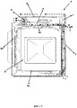
Figure 1 ; is a side sectional view of the white good provided within the known art. -
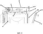
Figure 2 ; is a side sectional view of a detail of the white good developed with the present invention. -
Figure 3 ; is a side sectional view of the white good developed with the present invention when the door is in the opened position. -
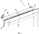
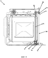
Figure 4 ; is a perspective view of another detail of the white good developed with the present invention. -
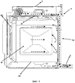
Figure 5 ; is a side sectional view of an embodiment of the white good developed with the present invention. -
Figure 6 ; is a side sectional view of another embodiment of the white good developed with the present invention. -
Figure 7 ; is a side sectional view of another embodiment of the white good developed with the present invention. -
Figure 8 ; is a perspective view of a flap arrangement comprised within the white good developed with the present invention. -
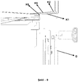
Figure 9 ; is a side sectional view of another detail of the white good developed with the present invention. -
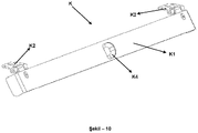
Figure 10 ; is a perspective view of another embodiment of the flap arrangement. -
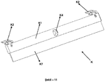
Figure 11 ; is a perspective view of another embodiment of the flap arrangement. -
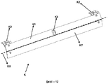
Figure 12 ; is a perspective view of another embodiment of the flap arrangement. - All the parts illustrated in figures are individually assigned a reference numeral and the corresponding terms of these numbers are listed below:
White good (A) Door (D) Fourth side (D1) Second protrusion (D2) Body (G) Channel (H) Fan (M) Control panel (P) Compartment (B) First side (B1) Second side (B2) Third side (B3) Opening (B4) Flap arrangement (K) First flap (K1) First hinge (K2) First sensor (K3) First protrusion (K4) Second hinge (K5) Joint (K6) Second flap (K7) Rotation axis (K8) Movement element (1a) Tension member (1b) First gear (2a) Second gear (2b) Transfer element (2c) Third gear (2d) Fourth gear (2e) Fifth gear (2f) Sixth gear (2g) Second sensor (3a) Motor (3b) - For the white goods such as ovens, a compartment comprised within the white good should have a high temperature during operation. However, this high temperature negatively affects the components located in the control panel where operation of the white good is arranged, and therefore the white good may be prevented to operate at a required efficacy. To this end, for such white goods within the known art, as shown in
figure 1 , a fan (M) is provided, and the fan (M) makes the outer environment air, having a temperature lower than the compartment (B), pass through a channel (H) which is in thermal interaction with the control panel (P) such that the components are prevented from being affected by the high temperature. The air, which is passed through the channel (K) and heated due to high temperature within the compartment (B), is transmitted to the outer environment through a cavity located between the door (D) and the control panel (P). However, this high temperature together with various gases formed in the compartment due to the high temperature, especially when the door of the white good is opened, may negatively affect the user and/or the furniture being close to the white good as well as said components. Within this context, with the present invention, there is developed a white good which prevents both the components in the control panel, the door, and the objects around the white good when the door is opened, from being negatively affected by the high temperature within the compartment and, an operation method for this white good. - The white good (A) developed with the present invention, exemplary views of which are illustrated in
figures 2-3 , comprises at least one body (G); at least one compartment (B) which is located in the body (G), which has a temperature higher than the outer environment temperature during the operation of the white good (A), which is surrounded by at least one first side (B1) (preferably top side or ceiling), at least one second side (B2) opposite to the first side (B1) (preferably bottom side or base), and at least one third side located between the first side (B1) and the second side (B2) such that it connects a part of the first side (B1) with a part of the second side (B2) being opposed to said part of the first side (B1), and which comprises at least one opening (B4) for access to inside that is preferably provided opposite to the third side (B3); at least one control panel (P) which is provided at the body (G), at a part of the first side (B1) which does not face the compartment (B) (preferably at a top part of the first side), and which arranges the operation of the white good (A); at least one door (D) which controls the access to the opening (B4), which has a closed position to prevent access to the opening (B4) and an opened position to allow access to the opening (B4), which is able to move for transition between these opened/closed positions (this movement may be both performed by rotating around an axis parallel to the second side (B2) as exemplified in the figures, and performed by sliding), which comprises at least one fourth side (D1) which approaches to and move away from the first side (B1) during this movement, wherein at least one cavity, being in connection with the outer environment, is formed between the control panel (P) (and preferably the first side B1)) and the door (A) when in the closed position; at least one channel (H), at least one part of which opens into the cavity, which has at least one inlet opening at at least another part, which is provided at the body (G) so as to be in thermal connection with the control panel (P) (preferably between the first side (B1) and the control panel (P)), and which, preferably, has a cross-sectional area that narrows from the inlet opening towards the cavity; at least one fan (M) which is provided at the body (G) preferably so as to be at the part where the inlet opening is provided, which draws, through at least one hole provided on the body (G), the outer environment air having a temperature lower than the temperature within the compartment (B), which directs this drawn air into the channel (H) through the inlet opening, and which enables the air to pass through the channel (H) so as to reach to the cavity, which, by this way, cools the control panel (P) in order not to damage the components at the control panel (P) by the temperature within the compartment (B), and which operates at at least one first operating speed (e.g. within the range of 800-1200 revolutions per minute) when the door (D) is in the closed position. The developed white good (A) also comprising at least one flap arrangement (K), exemplary embodiments of which are illustrated infigure 4 andfigure 8 tofigure 12 , which comprises: at least one first hinge (K2) (preferably at least two); at least one first flap (K1) which has a plate structure extending parallel to the first side (B1), which is in connection with the first hinge (K2) so as to be able to move by rotating around an axis via at least one torsion spring preferably located at the first hinge (K2), which has a first position that allows the air, reaching to the cavity through the channel (H), to pass to the outer environment when the door (D) is in closed position, and a second position that enables the air reaching to the cavity to be directed, preferably in parallel with the opening (B4) or vertically to the second side (B2), towards the opening (B4) (and therefore towards the second side (B2)) by posing an obstacle to the connection of the cavity with the outer environment when (D) the door is opened (in the second position, there is no angle other than 0° exists between the first hinge (K2) and the first flap (K1)); and at least one movement equipment which allows the first flap (K1) to be in the first position when the door (D) is in the closed position, and allows the first flap (K1) to take place in the second position when the door (D) is opened. - In an exemplary embodiment of the invention, when the white good (A) is operated, the temperature within the compartment (B) reaches to a higher temperature than the outer environment within which the white good (A) is present. For that reason, in order not to affect the control panel (P) which arranges the operation of the white good (A) by the high temperature at the compartment (B), when the white good (A) starts to operate, the fan (M) also starts to operate. When the fan (M) operates, the outer environment air is drawn through the hole provided at the body (G) such that it is directed to the channel (H) through the inlet opening. Due to the fact that the channel (H) is in thermal connection with the control panel (P), the outer environment air circulating in the channel (H) both prevents control panel (P) from being affected by the temperature in the compartment (B), and cools the control panel (P). In the meantime, because of the fact that the door (D) is closed, the first flap (K1) is in the first position, and therefore the cavity is in connection with the outer environment. By this way, the air circulating through the channel (H) reaches to the cavity to pass to the outer environment. As shown in
figure 3 , when the door is started to be opened, the first flap (K1) rotates around the axis, passing through the region where it is in connection with the first hinge (K2), by moving such that its free side which is not in connection with the first hinge (K2) moves away from the first hinge (K2), and takes place in the second position in which the first flap (K1) is inclined with respect to the first side (B1), by this way, pose an obstacle to the connection of the cavity with the outer environment, and enables the air, which reaches from the channel (H) to the cavity, to be directed to the opening (B4) and therefore to the second side (B2) other than the outer environment. By this way, an air curtain is formed between the opening (B4) and the door (D), and the air inside the compartment (B) is prevented from escaping directly to the outer environment such that the user, objects like furniture that are present around the white good (A) are able to be prevented from being negatively affected by the hot air and gases inside the compartment (B). In addition to this, thanks to using equipment that are already provided in the white good (A) and adding only the flap arrangement (K) to the white good (A), a white good (A) is obtained which is cheap, easy and practical to produce. - In a preferred embodiment of the invention, the fan (M) has at least one second operating speed (e.g. within the range of 1200-1500 revolutions per minute) higher than the first operating speed, and the developed white good (A) preferably comprises at least one first sensor (K3) which, by sensing movement of the first flap (K1), enables to operate the fan (M) at the first operating speed if the first flap (K1) is in the first position and to operate the fan (M) at the second operating speed if the first flap (K1) is in the second position, and which accordingly controls the operating speed of the fan (M). By this way, it is able to be provided to form a more efficient air curtain in front of the opening (B4). The first sensor (K3) may preferably be a mechanical switch, an ultrasonic sensor, a laser sensor, an inductive sensor, a light sensor or a capacitive sensor. Operating time change of the fan (M) can be performed mechanically by the first sensor (K3), or by a control unit comprised within the white good (A) such that the control unit processes the signals received from the first sensor (K3).
- In an embodiment of the invention which is shown in
figure 4 , the movement equipment preferably comprises at least one first protrusion (K4) provided at the surface of the first flap (K1) that faces the opening (B4) when in the first position, and at least one second protrusion (D2) provided at the fourth side (D1) of the door (D) so as to be in contact with the first protrusion (K4) when the first flap (K1) is in the first position. In this embodiment, while the door (D) takes place in the closed position from the opened position, the second protrusion (D2) contacts with the first flap (K4), thereby allowing the first flap (K1), being in the second position, to take place in the first position. When the door (D) takes place in the closed position, since the second protrusion (D2) and the first protrusion (K4) are in contact with each other, the first flap (K1) takes place in the first position so as to maintain this position until the door (D) starts to be opened. Therefore, when the door (D) is in the closed position, the first flap (K1) does not obstruct the connection of the cavity with the outer environment, and the air passing through the channel (H) is able to be delivered to the outer environment efficiently. - In another embodiment of the invention which is shown in
figure 5 , the movement equipment preferably comprises at least two movement elements (1a) (e.g. a coil, a pulley, a wheel etc.) which are provided such that at least one of them is at the part of the opening (B4) which is close to the first side (B1), and at least another of them is at the part of the opening (B4) which is close to the second side (B2); and at least one tension member (1b) (e.g. a rope, a wire etc.) which is connected, from at least one part, to the flap equipment (K) (to the first hinge (K2) or the first flap (K1)) by passing on the movement element (1a) which is provided at the part that is close to the first side (B1), and connected, from at least another part, to the door (D) (preferably to a part of the door (D) that is close to the second side (B2)) by passing on the movement element (1a) which is provided at the part that is close to the second side (B2), and which enables the first flap (K1) to take place in the second position when the door (D) takes place in the opened position, and enables the first flap (K1) to take place in the first position when the door (D) takes place in the closed position. Therefore, movement of the first flap (K1) is able to be practically controlled. - In another preferred embodiment which is shown in
figure 6 , the movement equipment comprises at least one first gear (2a) (e.g. a rack and pinion gear, a worm gear etc.) which is in connection with the door (D) and which is able to move with the movement of the door (D); at least one second gear (2b) (e.g. a pinion gear) which is in connection with the first gear (2a) and which transfer the movement of the first gear (2a) by moving (e.g. by rotating); at least one transfer element (2c) which is in connection with the second gear (2b) from at least one part, wherein the movement of the first gear (2a) (and therefore the door (D)) is transferred to the transfer element (2c) via the second gear (2b), which is able to rotate around its own axis as a result of this movement transfer, and which is preferably in the form of a shaft; and at least one third gear (2d) which is in connection with another part of the transfer element (2c) from one part, and in connection with the flap arrangement (K) from another part, which is able to move (e.g. rotate) with the rotational movement of the transfer element (2c), and which, as a result of this movement, enables the first flap (K1) to take place in the first or the second position. In this embodiment, when the door starts to open, it make the first gear (2a) move in a direction, and movement of the first gear (2a) and therefore of the door (D) is transferred to the transfer element (2c) via the second gear (2b). As a result of this movement transfer, the transfer element (2c) starts to rotate around its own axis in a direction (in clockwise or anti-clockwise), and with this rotational movement, it makes the third gear (2d) that is in connection with the transfer element move in a direction. Since the third gear (2d) is in connection with both the transfer element (2c) and the flap arrangement (K), the third gear (2d) allows the first flap (K1) to take place in the second position by moving with the movement received from the transfer element (2c). While the door (D) takes place in the closed position from the opened position, the first gear (2a) moves in a direction opposite to the movement direction occurring when the door (D) is opening, and this movement being in the opposite direction is transferred to the transfer element (2c) via the second gear (2b) such that the transfer element (2c) is enabled to rotate in a direction opposite to the rotation direction occurring when the door (D) is opening. This rotation of the transfer element (2c) which is in the opposite direction enables to move the third gear (2d) in a direction opposite to its initial movement direction, thus the first flap (K1) takes place in its first position when the door (D) is closed. Thanks to this embodiment, for the different opened positions of the door (D) (e.g. for different angles between the opening (B4) and the door (D)), various angles are provided between the first flap (K1) and the first hinge (K2) such that the first flap (K1) have different positions in the second position (e.g. the first flap (K1), in any position of the door (D) at each angle, can be allowed to be positioned so as to extend parallel to the fourth side (D1)). This case also provides to adjust the opening amount of the first flap (K1) according to the opening amount of the door (D) (in other words, obstructing the connection of the cavity with the outer environment)), thereby obtaining an efficient white good (A). In this embodiment, the developed white good (A) also preferably comprises at least one fourth gear (2e) which provides the connection of the third gear (2d) with the flap arrangement (K) (and therefore with the first flap (K1)) in order to be able to transfer the movement of the door (D) to the first flap (K1) in a more efficient manner, and at least one fifth gear (2f) which is located between the second gear (2b) and the transfer element (2c), and which transfers the movement of the second gear (2b) to the transfer element (2c). In another alternative embodiment, the white good (A) preferably comprises at least one sixth gear (2g) which is provided between the third gear (2d) and the fourth gear (2e), and which transfers the movement of the third gear (2d) to the fourth gear (2e). - In another exemplary embodiment shown in
figure 7 , the developed white good (A) preferably comprises at least one second sensor (3a) which senses the opened/closed positions of the door (D), and at least one motor (3b) which is in connection with the flap arrangement (K), and which enables the first flap (K1) to take place in the first position or the second position according to the opened/closed positions of the door (D) determined by the second sensor (3a). In this embodiment, the second sensor (3a) produces different signals according to the closed position, opened position of the door (D) and to the opening amount between the door (D) and the opening (B4), and the produced signals are transmitted to the control unit of the white good (A). In accordance with these signals, the control unit determines the angle amount that should be between the first hinge (K2) and the first flap (K1), and therefore determines the position that the first flap (K1) should have at the second position (e.g. the first flap (K1) is provided to be parallel to the fourth side (D1) continuously) and accordingly, adjusts the position of the first flap (K1) by energising the motor (3b). By this way, an efficient air curtain is provided to be formed at the opening (B4) so as to obtain a reliable white good (A). - In a preferred embodiment of the invention, the first hinge (K2) is in connection with the body (G) (preferably so as to be in a bottom region of the control panel (P)) from a part which is not in connection with the first flap (K1). In another preferred embodiment, the white good (A), as shown in
figure 8 andfigure 9 , comprises at least one second hinge (K5), wherein another part of the first hinge (K2) that is not in connection with the first flap (K1) is connected to at least one part of the second hinge (K5), and wherein the second hinge (K5), from at least another part, is connected to the body (G) via at least one joint (K6) so as to be able to achieve rotary movement in the joint (K6) axis. Thanks to the second hinge (K5), when the first flap (K1) takes place in the first position, it rotates in the joint (K6) axis, and it takes place an inclined position such that an acute angle is formed between the first flap (K1) and the second hinge (K5) (e.g. such that the part which is in connection with the first hinge (K2) is at a higher location than the part which is in connection with the body (G)). By this way, when the door (D) is in the closed position, the first flap (K1) is provided to be positioned such that the connection of the cavity with the outer environment is not obstructed even a little, thereby obtaining an efficient white good (A). - In another alternative embodiment of the invention which is provided in
figure 10 , preferably, at least one end part of the first flap (K1) (preferably both of the end parts) has a folded structure such that it forms a lug towards the part of the first flap (K1) facing the first hinge (K2) when in the first position. By this way, when the first flap (K1) is in the second position, the air reaching to the cavity through the channel (H) is prevented from escaping to the outer environment from these end parts such that all of the air is utilised in formation of the air curtain, thereby increasing the efficacy of the air curtain. - In another exemplary embodiment the developed white good (A), as shown in
figure 11 , preferably comprises at least one second flap (K7) which is in connection with the first flap (K1) so as to move on the first flap (K1) by sliding (preferably at the part of the first flap (K1) facing the first hinge (K2) when in the first position); and by this way, which, when the first flap (K1) is in the second position, is provided collaterally (or one on the top of the other) with the first flap (K1) such that it moves away from the first flap (K1) from the side of the first flap (K1) being opposite to the side that is in connection with the first hinge (K2) (in other words, such that it extends towards the door (D) or the opening or the second side (B1)); and which, when the first flap (K1) is in the first position, is provided on the first flap (K1) (preferably between the first flap (K1) and the first hinge (K2)) such that it matches up with the first flap (K1). By this way, the air reaching to the cavity is provided to form an air curtain in a more efficient manner. - In another embodiment provided in
figure 12 , the white good (A) preferably comprises at least one second flap (K7) which is connected to a side of the first flap (K1) being opposite to the side that is in connection with the first hinge (K2) such that it is able to move by rotating around a rotation axis (K8) parallel to said opposite side; which, when the first flap (K1) is in the second position, is provided collaterally (or one on the top of the other) with the first flap (K1) such that it moves away from the first flap (K1) from the opposite side (in other words, such that it extends towards the door (D) or the opening or the second side (B1)); and which, when the first flap (K1) is in the first position, is provided on the first flap (K1) (preferably between the first flap (K1) and the first hinge (K2)) such that it matches up with the first flap (K1) by rotating around the rotation axis (K8). In this embodiment, while the first flap (K1) takes place in the second position from the first position, the second flap (K7) positions alongside the first flap (K1) by rotating around the rotation axis (K8) such that the side being in connection with the first flap (K1) is collateral to said opposite side of the first flap (K1). Also, while the first flap (K1) returns to the first position, it laps on the first flap (K1) by rotating around the rotation axis (K8). Thanks to this embodiment, connection of the cavity with the outer environment is obstructed in a more efficient manner, and the air amount transmitted to the opening (B4) is increased such that the air curtain becomes more efficient. - In another embodiment of the invention, the developed white good (A) preferably comprises at least one suction hole (preferably more than one) provided at the part (preferably at the side) of the door (D) that is close to the second side (B2), and at least one air circulation channel which is provided within the door (D), a part of which opens into the suction hole, and another partof which opens into the cavity. In this embodiment, when the door (D) is in the closed position, with the negative pressure forming due to heated air which reaches to the cavity through the channel (H) and which is sent to the outer environment through the cavity; the outer environment air is sucked through the suction hole such that it is received to the air circulation channel, and the air passing through the air circulation channel is sent to the outer environment through the cavity. By this way, the door (D) is prevented from being affected by the high temperature of the compartment (B).
- In the operation method of the white good (A) developed by the present invention, the fan (M), which has the first operating speed and the second operating speed and which operates at the first operating speed when the door (D) is in the closed position, is provided to operate immediately at the second operating speed via the first sensor (K3) when the door (D) opens. In another preferred embodiment, the fan (M) operating at the first operating speed is provided to operate at the second operating speed via the first sensor (K3) following a first time after the door (D) opens. Thanks to this embodiment, while the door (D) is opening, the air having a temperature lower than the temperature of the compartment (B) is provided to be received inside the compartment (B) in fewer amounts such that the air within the compartment (B) is provided to be hotter. In another preferred embodiment, after being operated at the second operating speed for a second time, the fan (M) is passed to the first operating speed again via the first sensor (K3). The second time is determined to be such a time that the air having a high temperature within the compartment (B) is lowered to a temperature which does not harm any object. By this way, the fan (M) is prevented from consuming energy unnecessarily, and the user is provided to be minimally affected by the loud noise forming due to operation of the fan (M) at high revolutions.
- Thanks to the white good (A) and the operation method developed by the present invention, it is provided that the air directed to the outer environment by the fan (M), which enables to cool the components that are already provided at the white good (A) and located at the control panel (P), forms an air curtain between the opening (B4) and the door (D) by being directed to the compartment (B) opening (B4) when the door (D) is in the closed position; therefore objects around the white good (A) can be prevented to be negatively affected by the air and gases of high temperature which are released from the compartment (B) to the outer environment when the door (D) is opened, and thus, a white good (A) is obtained which is cheap, easy and practical to produce.
Claims (15)
- A white good (A) comprising:at least one body (G);at least one compartment (B) which is located in the body (G), which has a temperature higher than the outer environment temperature during the operation, which is surrounded by at least one first side (B1), at least one second side (B2) opposite to the first side (B1),and at least one third side (B3) located between the first side (B1) and the second side (B2) such that it connects a part of the first side (B1) with a part of the second side (B2) being opposed to said part of the first side (B1), and which comprises at least one opening (B4) for access to inside;at least one control panel (P) which is provided at the body (G), at a part of the first side (B1) which does not face the compartment (B), and which arranges the operation of the white good (A);at least one door (D) which controls the access to the opening (B4), which has a closed position to prevent access to the opening (B4) and an opened position to allow access to the opening (B4), which is able to move for transition between these opened/closed positions, which comprises at least one fourth side (D1) which approaches to and move away from the first side (B1) during this movement, wherein at least one cavity, being in connection with the outer environment, is formed between the control panel (P) and the door (D) when in the closed position;at least one channel (H), at least one part of which opens into the cavity, which has at least one inlet opening at at least another part, and which is provided at the body (G) so as to be in thermal connection with the control panel (P); andat least one fan (M) which is provided at the body (G), which draws, through at least one hole provided on the body (G), the outer environment air having a temperature lower than the temperature within the compartment (B), which directs this drawn air into the channel (H) through the inlet opening, which enables the air to pass through the channel (H) so as to reach to the cavity, and which operates at at least one first operating speed when the door (D) is in the closed position;characterized by comprising at least one flap arrangement (K) which comprises:• at least one first hinge (K2);• at least one first flap (K1) which has a plate structure extending parallel to the first side (B1), which is in connection with the first hinge (K2) so as to be able to move by rotating around an axis, which has a first position that allows the air, reaching to the cavity through the channel (H), to pass to the outer environment when the door (D) is in closed position, and a second position that enables the air reaching to the cavity to be directed towards the opening (B4) by posing an obstacle to the connection of the cavity with the outer environment when the door (D) is opened; and• at least one movement equipment which allows the first flap (K1) to be in the first position when the door (D) is in the closed position, and allows the first flap (K1) to take place in the second position when the door (D) is opened.
- A white good (A) according to Claim 1, characterized in that the channel (H) is provided between the first side (B1) and the control panel (P).
- A white good (A) according to Claim 1, characterized in that the first flap (K1) is positioned in the second position so as to direct the air, reaching to the cavity, in parallel with the opening (B4) or vertically to the second side (B2).
- A white good (A) according to Claim 1, characterized in that the fan (M) has at least one second operating speed higher than the first operating speed, and that the white good (A) comprises at least one first sensor (K3) which, by sensing movement of the first flap (K1), enables to operate the fan (M) at the first operating speed if the first flap (K1) is in the first position and to operate the fan (M) at the second operating speed if the first flap (K1) is in the second position, and which accordingly controls the operating speed of the fan (M).
- A white good (A) according to Claim 1, characterized in that the movement equipment comprises at least one first protrusion (K4) provided at the surface of the first flap (K1) that faces the opening (B4) when in the first position, and at least one second protrusion (D2) provided at the fourth side (D1) of the door (D) so as to be in contact with the first protrusion (K4) when the first flap (K1) is in the first position.
- A white good (A) according to Claim 1, characterized in that the movement equipment comprises at least two movement elements (1a) which are provided such that at least one of them is at the part of the opening (B4) which is close to the first side (B1), and at least another of them is at the part of the opening (B4) which is close to the second side (B2); and at least one tension member (1b) which is connected, from at least one part, to the flap equipment (K) by passing on the movement element (1a) which is provided at the part that is close to the first side (B1), and connected, from at least another part, to the door (D) by passing on the movement element (1a) which is provided at the part that is close to the second side (B2), and which enables the first flap (K1) to take place in the second position when the door (D) takes place in the opened position, and enables the first flap (K1) to take place in the first position when the door (D) takes place in the closed position.
- A white good (A) according to Claim 1, characterized in that the movement equipment comprises at least one first gear (2a) which is in connection with the door (D) and which is able to move with the movement of the door (D); at least one second gear (2b) which is in connection with the first gear (2a) and which transfer the movement of the first gear (2a) by moving; at least one transfer element (2c) which is in connection with the second gear (2b) from at least one part, wherein the movement of the first gear (2a) is transferred to the transfer element (2c) via the second gear (2b), and which is able to rotate around its own axis as a result of this movement transfer; and at least one third gear (2d) which is in connection with another part of the transfer element (2c) from one part, and in connection with the flap arrangement (K) from another part, which is able to move with the rotational movement of the transfer element (2c), and which, as a result of this movement, enables the first flap (K1) to take place in the first or the second position.
- A white good (A) according to Claim 7, characterized in that the movement equipment comprises at least one fourth gear (2e) which provides the connection of the third gear (2d) with the flap arrangement (K); at least one fifth gear (2f) which is located between the second gear (2b) and the transfer element (2c), and which transfers the movement of the second gear (2b) to the transfer element (2c); and at least one sixth gear (2g) which is provided between the third gear (2d) and the fourth gear (2e), and which transfers the movement of the third gear (2d) to the fourth gear (2e).
- A white good (A) according to Claim 1, characterized by comprising at least one second sensor (3a) which senses the opened/closed positions of the door (D), and at least one motor (3b) which is in connection with the flap arrangement (K), and which enables the first flap (K1) to take place in the first position or the second position according to the opened/closed positions of the door (D) determined by the second sensor (3a).
- A white good (A) according to Claim 1, characterized by comprising at least one second hinge (K5), wherein another part of the first hinge (K2) that is not in connection with the first flap (K1) is connected to at least one part of the second hinge (K5), and wherein the second hinge (K5), from at least another part, is connected to the body (G) via at least one joint (K6) so as to be able to achieve rotary movement in the joint (K6) axis.
- A white good (A) according to Claim 1, characterized by comprising at least one second flap (K7) which is in connection with the first flap (K1) so as to be able to move on the first flap (K1) by sliding; and by this way, which, when the first flap (K1) is in the second position, is provided collaterally with the first flap (K1) such that it moves away from the first flap (K1) from the side of the first flap (K1) being opposite to the side that is in connection with the first hinge (K2); and which, when the first flap (K1) is in the first position, is provided to be at the part of the first flap (K1) facing the first hinge (K2), and provided on the first flap (K1) such that it matches up with the first flap (K1).
- A white good (A) according to Claim 1, characterized by comprising at least one second flap (K7) which is connected to a side of the first flap (K1) being opposite to the side that is in connection with the first hinge (K2) such that it is able to move by rotating around a rotation axis (K8) parallel to said opposite side; which, when the first flap (K1) is in the second position, is provided collaterally with the first flap (K1) such that it moves away from the first flap (K1) from the opposite side; and which, when the first flap (K1) is in the first position, is provided on the first flap (K1) such that it matches up with the first flap (K1) by rotating around the rotation axis (K8).
- A white good (A) according any of the preceding claims, characterized by comprising at least one suction hole provided at the part of the door (D) that is close to the second side (B2), and at least one air circulation channel which is provided within the door (D), a part of which opens into the suction hole, and another part of which opens into the cavity.
- An operation method for a white good (A) according to Claim 4, characterized in that the fan (M) operating at the first operating speed when the door (D) is in the closed position starts to operate at the second operating speed via the first sensor (K3) when the door (D) is opened, immediately, or following a first time after the door (D) opens.
- An operation method according to Claim 14, characterized in that the method comprises the steps of operating the fan (M) at the second operating speed for a second time, and at the end of the second time, making the fan (M) pass to the first operating speed again via the first sensor (K3), and that the second time is determined to be such a time that the air having a high temperature within the compartment (B) is lowered to a temperature which does not harm any object.
Applications Claiming Priority (1)
| Application Number | Priority Date | Filing Date | Title |
|---|---|---|---|
| TR2017/12959A TR201712959A2 (en) | 2017-08-29 | 2017-08-29 | A White Goods And Working Method |
Publications (3)
| Publication Number | Publication Date |
|---|---|
| EP3450857A2 true EP3450857A2 (en) | 2019-03-06 |
| EP3450857A3 EP3450857A3 (en) | 2019-05-22 |
| EP3450857B1 EP3450857B1 (en) | 2022-03-02 |
Family
ID=63168274
Family Applications (1)
| Application Number | Title | Priority Date | Filing Date |
|---|---|---|---|
| EP18186460.4A Active EP3450857B1 (en) | 2017-08-29 | 2018-07-31 | A white good |
Country Status (3)
| Country | Link |
|---|---|
| EP (1) | EP3450857B1 (en) |
| ES (1) | ES2910186T3 (en) |
| TR (1) | TR201712959A2 (en) |
Cited By (6)
| Publication number | Priority date | Publication date | Assignee | Title |
|---|---|---|---|---|
| CN112438616A (en) * | 2019-08-31 | 2021-03-05 | 宁波方太厨具有限公司 | Door body and cooking device with same |
| CN112902233A (en) * | 2021-01-25 | 2021-06-04 | 宁波方太厨具有限公司 | Cooking equipment and integrated kitchen |
| WO2022238100A1 (en) | 2021-05-11 | 2022-11-17 | Miele & Cie. Kg | Method for cooling vapours or steam escaping from the cooking chamber of a cooking appliance, and cooking appliance |
| DE102023132625A1 (en) | 2023-11-23 | 2024-11-14 | Miele & Cie. Kg | cooking facility |
| DE102023132899A1 (en) * | 2023-11-24 | 2025-05-28 | Miele & Cie. Kg | Cooking device and method for operating |
| EP4560200A1 (en) | 2023-11-23 | 2025-05-28 | Miele & Cie. KG | Cooking device and method for operating |
Families Citing this family (2)
| Publication number | Priority date | Publication date | Assignee | Title |
|---|---|---|---|---|
| USD1005769S1 (en) | 2021-09-08 | 2023-11-28 | Newage Products Inc. | Oven |
| US12402631B2 (en) | 2021-09-08 | 2025-09-02 | Newage Products Inc. | Oven |
Citations (1)
| Publication number | Priority date | Publication date | Assignee | Title |
|---|---|---|---|---|
| US3387600A (en) | 1966-04-13 | 1968-06-11 | Berj A. Terzian | Oven with automatic air curtain means |
Family Cites Families (5)
| Publication number | Priority date | Publication date | Assignee | Title |
|---|---|---|---|---|
| JPS625066A (en) * | 1985-06-28 | 1987-01-12 | 株式会社日立製作所 | Household refrigerator |
| JPH0634143A (en) * | 1992-07-21 | 1994-02-08 | Toshiba Corp | Heating cooker |
| KR102124833B1 (en) * | 2013-09-11 | 2020-06-19 | 삼성전자주식회사 | Oven |
| EP3091291A1 (en) * | 2015-05-08 | 2016-11-09 | Electrolux Appliances Aktiebolag | A cooking oven with an oven cavity and an oven door |
| KR20170035455A (en) * | 2015-09-23 | 2017-03-31 | 삼성전자주식회사 | Oven and controlling method thereof |
-
2017
- 2017-08-29 TR TR2017/12959A patent/TR201712959A2/en unknown
-
2018
- 2018-07-31 EP EP18186460.4A patent/EP3450857B1/en active Active
- 2018-07-31 ES ES18186460T patent/ES2910186T3/en active Active
Patent Citations (1)
| Publication number | Priority date | Publication date | Assignee | Title |
|---|---|---|---|---|
| US3387600A (en) | 1966-04-13 | 1968-06-11 | Berj A. Terzian | Oven with automatic air curtain means |
Cited By (9)
| Publication number | Priority date | Publication date | Assignee | Title |
|---|---|---|---|---|
| CN112438616A (en) * | 2019-08-31 | 2021-03-05 | 宁波方太厨具有限公司 | Door body and cooking device with same |
| CN112438616B (en) * | 2019-08-31 | 2022-02-18 | 宁波方太厨具有限公司 | Door body and cooking device with same |
| CN112902233A (en) * | 2021-01-25 | 2021-06-04 | 宁波方太厨具有限公司 | Cooking equipment and integrated kitchen |
| WO2022238100A1 (en) | 2021-05-11 | 2022-11-17 | Miele & Cie. Kg | Method for cooling vapours or steam escaping from the cooking chamber of a cooking appliance, and cooking appliance |
| BE1029396A1 (en) | 2021-05-11 | 2022-12-07 | Miele & Cie | Process for cooling the vapor or steam escaping from the cooking chamber of a cooking appliance and cooking appliance |
| DE102023132625A1 (en) | 2023-11-23 | 2024-11-14 | Miele & Cie. Kg | cooking facility |
| EP4560200A1 (en) | 2023-11-23 | 2025-05-28 | Miele & Cie. KG | Cooking device and method for operating |
| DE102023132899A1 (en) * | 2023-11-24 | 2025-05-28 | Miele & Cie. Kg | Cooking device and method for operating |
| DE102023132899B4 (en) * | 2023-11-24 | 2025-08-28 | Miele & Cie. Kg | Cooking device and method for operating |
Also Published As
| Publication number | Publication date |
|---|---|
| TR201712959A2 (en) | 2019-03-21 |
| EP3450857B1 (en) | 2022-03-02 |
| ES2910186T3 (en) | 2022-05-11 |
| EP3450857A3 (en) | 2019-05-22 |
Similar Documents
| Publication | Publication Date | Title |
|---|---|---|
| EP3450857A2 (en) | A white good and operation method | |
| US8212188B2 (en) | Cooking apparatus and method of controlling the same | |
| JP4335937B2 (en) | Air conditioner | |
| EP2363648A2 (en) | Oven | |
| KR102464262B1 (en) | Household electrical appliances having with door key linked to rotation movement of door | |
| US20100155039A1 (en) | Domestic appliance with an open air duct | |
| KR20100073121A (en) | Ceiling type air conditioner | |
| CN111035276B (en) | A embedded oven that is used for oven door subassembly of embedded oven and has it | |
| KR100909870B1 (en) | Indoor unit for air conditioner | |
| US6142866A (en) | Method and apparatus for providing air circulation control for a base transceiver station | |
| JP4950001B2 (en) | Air conditioner | |
| EP1752713B1 (en) | Indoor unit of air conditioner | |
| EP2180259A1 (en) | Food baking oven with airflow control devices | |
| KR20220138157A (en) | Cooking apparatus | |
| JP2009257606A (en) | Air conditioner | |
| JP5059661B2 (en) | Air conditioner | |
| JP5038092B2 (en) | Air conditioner | |
| KR19990039978A (en) | Microwave Sensor Moisture Proof Device | |
| KR100551198B1 (en) | Control method of opening and closing the discharge port of air conditioner | |
| JP2005300109A (en) | Cooker | |
| US20240049367A1 (en) | Cooking appliance | |
| US20260126185A1 (en) | Cooking appliance and control method thereof | |
| KR20090105418A (en) | Air conditioner and control method | |
| JP5517747B2 (en) | Cooker | |
| KR20140077508A (en) | Pressure regulator for vehicle and vehicle comprising the same |
Legal Events
| Date | Code | Title | Description |
|---|---|---|---|
| PUAI | Public reference made under article 153(3) epc to a published international application that has entered the european phase |
Free format text: ORIGINAL CODE: 0009012 |
|
| STAA | Information on the status of an ep patent application or granted ep patent |
Free format text: STATUS: THE APPLICATION HAS BEEN PUBLISHED |
|
| AK | Designated contracting states |
Kind code of ref document: A2 Designated state(s): AL AT BE BG CH CY CZ DE DK EE ES FI FR GB GR HR HU IE IS IT LI LT LU LV MC MK MT NL NO PL PT RO RS SE SI SK SM TR |
|
| AX | Request for extension of the european patent |
Extension state: BA ME |
|
| PUAL | Search report despatched |
Free format text: ORIGINAL CODE: 0009013 |
|
| AK | Designated contracting states |
Kind code of ref document: A3 Designated state(s): AL AT BE BG CH CY CZ DE DK EE ES FI FR GB GR HR HU IE IS IT LI LT LU LV MC MK MT NL NO PL PT RO RS SE SI SK SM TR |
|
| AX | Request for extension of the european patent |
Extension state: BA ME |
|
| RIC1 | Information provided on ipc code assigned before grant |
Ipc: F24C 15/02 20060101ALI20190418BHEP Ipc: F24C 15/00 20060101ALI20190418BHEP Ipc: F24C 15/32 20060101AFI20190418BHEP |
|
| STAA | Information on the status of an ep patent application or granted ep patent |
Free format text: STATUS: REQUEST FOR EXAMINATION WAS MADE |
|
| 17P | Request for examination filed |
Effective date: 20191120 |
|
| RBV | Designated contracting states (corrected) |
Designated state(s): AL AT BE BG CH CY CZ DE DK EE ES FI FR GB GR HR HU IE IS IT LI LT LU LV MC MK MT NL NO PL PT RO RS SE SI SK SM TR |
|
| STAA | Information on the status of an ep patent application or granted ep patent |
Free format text: STATUS: EXAMINATION IS IN PROGRESS |
|
| 17Q | First examination report despatched |
Effective date: 20200407 |
|
| GRAP | Despatch of communication of intention to grant a patent |
Free format text: ORIGINAL CODE: EPIDOSNIGR1 |
|
| STAA | Information on the status of an ep patent application or granted ep patent |
Free format text: STATUS: GRANT OF PATENT IS INTENDED |
|
| INTG | Intention to grant announced |
Effective date: 20211006 |
|
| GRAS | Grant fee paid |
Free format text: ORIGINAL CODE: EPIDOSNIGR3 |
|
| GRAA | (expected) grant |
Free format text: ORIGINAL CODE: 0009210 |
|
| STAA | Information on the status of an ep patent application or granted ep patent |
Free format text: STATUS: THE PATENT HAS BEEN GRANTED |
|
| AK | Designated contracting states |
Kind code of ref document: B1 Designated state(s): AL AT BE BG CH CY CZ DE DK EE ES FI FR GB GR HR HU IE IS IT LI LT LU LV MC MK MT NL NO PL PT RO RS SE SI SK SM TR |
|
| REG | Reference to a national code |
Ref country code: GB Ref legal event code: FG4D |
|
| REG | Reference to a national code |
Ref country code: CH Ref legal event code: EP Ref country code: AT Ref legal event code: REF Ref document number: 1472537 Country of ref document: AT Kind code of ref document: T Effective date: 20220315 |
|
| REG | Reference to a national code |
Ref country code: DE Ref legal event code: R096 Ref document number: 602018031494 Country of ref document: DE |
|
| REG | Reference to a national code |
Ref country code: IE Ref legal event code: FG4D |
|
| REG | Reference to a national code |
Ref country code: ES Ref legal event code: FG2A Ref document number: 2910186 Country of ref document: ES Kind code of ref document: T3 Effective date: 20220511 |
|
| REG | Reference to a national code |
Ref country code: LT Ref legal event code: MG9D |
|
| REG | Reference to a national code |
Ref country code: NL Ref legal event code: MP Effective date: 20220302 |
|
| PG25 | Lapsed in a contracting state [announced via postgrant information from national office to epo] |
Ref country code: SE Free format text: LAPSE BECAUSE OF FAILURE TO SUBMIT A TRANSLATION OF THE DESCRIPTION OR TO PAY THE FEE WITHIN THE PRESCRIBED TIME-LIMIT Effective date: 20220302 Ref country code: RS Free format text: LAPSE BECAUSE OF FAILURE TO SUBMIT A TRANSLATION OF THE DESCRIPTION OR TO PAY THE FEE WITHIN THE PRESCRIBED TIME-LIMIT Effective date: 20220302 Ref country code: NO Free format text: LAPSE BECAUSE OF FAILURE TO SUBMIT A TRANSLATION OF THE DESCRIPTION OR TO PAY THE FEE WITHIN THE PRESCRIBED TIME-LIMIT Effective date: 20220602 Ref country code: LT Free format text: LAPSE BECAUSE OF FAILURE TO SUBMIT A TRANSLATION OF THE DESCRIPTION OR TO PAY THE FEE WITHIN THE PRESCRIBED TIME-LIMIT Effective date: 20220302 Ref country code: HR Free format text: LAPSE BECAUSE OF FAILURE TO SUBMIT A TRANSLATION OF THE DESCRIPTION OR TO PAY THE FEE WITHIN THE PRESCRIBED TIME-LIMIT Effective date: 20220302 Ref country code: BG Free format text: LAPSE BECAUSE OF FAILURE TO SUBMIT A TRANSLATION OF THE DESCRIPTION OR TO PAY THE FEE WITHIN THE PRESCRIBED TIME-LIMIT Effective date: 20220602 |
|
| REG | Reference to a national code |
Ref country code: AT Ref legal event code: MK05 Ref document number: 1472537 Country of ref document: AT Kind code of ref document: T Effective date: 20220302 |
|
| PG25 | Lapsed in a contracting state [announced via postgrant information from national office to epo] |
Ref country code: PL Free format text: LAPSE BECAUSE OF FAILURE TO SUBMIT A TRANSLATION OF THE DESCRIPTION OR TO PAY THE FEE WITHIN THE PRESCRIBED TIME-LIMIT Effective date: 20220302 Ref country code: LV Free format text: LAPSE BECAUSE OF FAILURE TO SUBMIT A TRANSLATION OF THE DESCRIPTION OR TO PAY THE FEE WITHIN THE PRESCRIBED TIME-LIMIT Effective date: 20220302 Ref country code: GR Free format text: LAPSE BECAUSE OF FAILURE TO SUBMIT A TRANSLATION OF THE DESCRIPTION OR TO PAY THE FEE WITHIN THE PRESCRIBED TIME-LIMIT Effective date: 20220603 Ref country code: FI Free format text: LAPSE BECAUSE OF FAILURE TO SUBMIT A TRANSLATION OF THE DESCRIPTION OR TO PAY THE FEE WITHIN THE PRESCRIBED TIME-LIMIT Effective date: 20220302 |
|
| PG25 | Lapsed in a contracting state [announced via postgrant information from national office to epo] |
Ref country code: NL Free format text: LAPSE BECAUSE OF FAILURE TO SUBMIT A TRANSLATION OF THE DESCRIPTION OR TO PAY THE FEE WITHIN THE PRESCRIBED TIME-LIMIT Effective date: 20220302 |
|
| REG | Reference to a national code |
Ref country code: DE Ref legal event code: R084 Ref document number: 602018031494 Country of ref document: DE |
|
| PG25 | Lapsed in a contracting state [announced via postgrant information from national office to epo] |
Ref country code: SM Free format text: LAPSE BECAUSE OF FAILURE TO SUBMIT A TRANSLATION OF THE DESCRIPTION OR TO PAY THE FEE WITHIN THE PRESCRIBED TIME-LIMIT Effective date: 20220302 Ref country code: SK Free format text: LAPSE BECAUSE OF FAILURE TO SUBMIT A TRANSLATION OF THE DESCRIPTION OR TO PAY THE FEE WITHIN THE PRESCRIBED TIME-LIMIT Effective date: 20220302 Ref country code: RO Free format text: LAPSE BECAUSE OF FAILURE TO SUBMIT A TRANSLATION OF THE DESCRIPTION OR TO PAY THE FEE WITHIN THE PRESCRIBED TIME-LIMIT Effective date: 20220302 Ref country code: PT Free format text: LAPSE BECAUSE OF FAILURE TO SUBMIT A TRANSLATION OF THE DESCRIPTION OR TO PAY THE FEE WITHIN THE PRESCRIBED TIME-LIMIT Effective date: 20220704 Ref country code: EE Free format text: LAPSE BECAUSE OF FAILURE TO SUBMIT A TRANSLATION OF THE DESCRIPTION OR TO PAY THE FEE WITHIN THE PRESCRIBED TIME-LIMIT Effective date: 20220302 Ref country code: CZ Free format text: LAPSE BECAUSE OF FAILURE TO SUBMIT A TRANSLATION OF THE DESCRIPTION OR TO PAY THE FEE WITHIN THE PRESCRIBED TIME-LIMIT Effective date: 20220302 Ref country code: AT Free format text: LAPSE BECAUSE OF FAILURE TO SUBMIT A TRANSLATION OF THE DESCRIPTION OR TO PAY THE FEE WITHIN THE PRESCRIBED TIME-LIMIT Effective date: 20220302 |
|
| PG25 | Lapsed in a contracting state [announced via postgrant information from national office to epo] |
Ref country code: IS Free format text: LAPSE BECAUSE OF FAILURE TO SUBMIT A TRANSLATION OF THE DESCRIPTION OR TO PAY THE FEE WITHIN THE PRESCRIBED TIME-LIMIT Effective date: 20220702 Ref country code: AL Free format text: LAPSE BECAUSE OF FAILURE TO SUBMIT A TRANSLATION OF THE DESCRIPTION OR TO PAY THE FEE WITHIN THE PRESCRIBED TIME-LIMIT Effective date: 20220302 |
|
| REG | Reference to a national code |
Ref country code: DE Ref legal event code: R097 Ref document number: 602018031494 Country of ref document: DE |
|
| PLBE | No opposition filed within time limit |
Free format text: ORIGINAL CODE: 0009261 |
|
| STAA | Information on the status of an ep patent application or granted ep patent |
Free format text: STATUS: NO OPPOSITION FILED WITHIN TIME LIMIT |
|
| PG25 | Lapsed in a contracting state [announced via postgrant information from national office to epo] |
Ref country code: DK Free format text: LAPSE BECAUSE OF FAILURE TO SUBMIT A TRANSLATION OF THE DESCRIPTION OR TO PAY THE FEE WITHIN THE PRESCRIBED TIME-LIMIT Effective date: 20220302 |
|
| 26N | No opposition filed |
Effective date: 20221205 |
|
| PG25 | Lapsed in a contracting state [announced via postgrant information from national office to epo] |
Ref country code: SI Free format text: LAPSE BECAUSE OF FAILURE TO SUBMIT A TRANSLATION OF THE DESCRIPTION OR TO PAY THE FEE WITHIN THE PRESCRIBED TIME-LIMIT Effective date: 20220302 Ref country code: MC Free format text: LAPSE BECAUSE OF FAILURE TO SUBMIT A TRANSLATION OF THE DESCRIPTION OR TO PAY THE FEE WITHIN THE PRESCRIBED TIME-LIMIT Effective date: 20220302 |
|
| REG | Reference to a national code |
Ref country code: CH Ref legal event code: PL |
|
| REG | Reference to a national code |
Ref country code: BE Ref legal event code: MM Effective date: 20220731 |
|
| PG25 | Lapsed in a contracting state [announced via postgrant information from national office to epo] |
Ref country code: LU Free format text: LAPSE BECAUSE OF NON-PAYMENT OF DUE FEES Effective date: 20220731 Ref country code: LI Free format text: LAPSE BECAUSE OF NON-PAYMENT OF DUE FEES Effective date: 20220731 Ref country code: FR Free format text: LAPSE BECAUSE OF NON-PAYMENT OF DUE FEES Effective date: 20220731 Ref country code: CH Free format text: LAPSE BECAUSE OF NON-PAYMENT OF DUE FEES Effective date: 20220731 |
|
| PG25 | Lapsed in a contracting state [announced via postgrant information from national office to epo] |
Ref country code: BE Free format text: LAPSE BECAUSE OF NON-PAYMENT OF DUE FEES Effective date: 20220731 |
|
| PG25 | Lapsed in a contracting state [announced via postgrant information from national office to epo] |
Ref country code: IT Free format text: LAPSE BECAUSE OF FAILURE TO SUBMIT A TRANSLATION OF THE DESCRIPTION OR TO PAY THE FEE WITHIN THE PRESCRIBED TIME-LIMIT Effective date: 20220302 Ref country code: IE Free format text: LAPSE BECAUSE OF NON-PAYMENT OF DUE FEES Effective date: 20220731 |
|
| PG25 | Lapsed in a contracting state [announced via postgrant information from national office to epo] |
Ref country code: HU Free format text: LAPSE BECAUSE OF FAILURE TO SUBMIT A TRANSLATION OF THE DESCRIPTION OR TO PAY THE FEE WITHIN THE PRESCRIBED TIME-LIMIT; INVALID AB INITIO Effective date: 20180731 |
|
| PG25 | Lapsed in a contracting state [announced via postgrant information from national office to epo] |
Ref country code: MK Free format text: LAPSE BECAUSE OF FAILURE TO SUBMIT A TRANSLATION OF THE DESCRIPTION OR TO PAY THE FEE WITHIN THE PRESCRIBED TIME-LIMIT Effective date: 20220302 Ref country code: CY Free format text: LAPSE BECAUSE OF FAILURE TO SUBMIT A TRANSLATION OF THE DESCRIPTION OR TO PAY THE FEE WITHIN THE PRESCRIBED TIME-LIMIT Effective date: 20220302 |
|
| PG25 | Lapsed in a contracting state [announced via postgrant information from national office to epo] |
Ref country code: TR Free format text: LAPSE BECAUSE OF FAILURE TO SUBMIT A TRANSLATION OF THE DESCRIPTION OR TO PAY THE FEE WITHIN THE PRESCRIBED TIME-LIMIT Effective date: 20220302 |
|
| PG25 | Lapsed in a contracting state [announced via postgrant information from national office to epo] |
Ref country code: MT Free format text: LAPSE BECAUSE OF FAILURE TO SUBMIT A TRANSLATION OF THE DESCRIPTION OR TO PAY THE FEE WITHIN THE PRESCRIBED TIME-LIMIT Effective date: 20220302 |
|
| PGFP | Annual fee paid to national office [announced via postgrant information from national office to epo] |
Ref country code: ES Payment date: 20250826 Year of fee payment: 8 |
|
| PGFP | Annual fee paid to national office [announced via postgrant information from national office to epo] |
Ref country code: DE Payment date: 20250722 Year of fee payment: 8 |
|
| PGFP | Annual fee paid to national office [announced via postgrant information from national office to epo] |
Ref country code: GB Payment date: 20250722 Year of fee payment: 8 |