EP3450843A1 - Nozzle structure for hydrogen gas burner apparatus - Google Patents
Nozzle structure for hydrogen gas burner apparatus Download PDFInfo
- Publication number
- EP3450843A1 EP3450843A1 EP18185028.0A EP18185028A EP3450843A1 EP 3450843 A1 EP3450843 A1 EP 3450843A1 EP 18185028 A EP18185028 A EP 18185028A EP 3450843 A1 EP3450843 A1 EP 3450843A1
- Authority
- EP
- European Patent Office
- Prior art keywords
- hydrogen gas
- inner tube
- oxygen
- circumferential surface
- tube
- Prior art date
- Legal status (The legal status is an assumption and is not a legal conclusion. Google has not performed a legal analysis and makes no representation as to the accuracy of the status listed.)
- Granted
Links
Images




Classifications
-
- F—MECHANICAL ENGINEERING; LIGHTING; HEATING; WEAPONS; BLASTING
- F23—COMBUSTION APPARATUS; COMBUSTION PROCESSES
- F23D—BURNERS
- F23D14/00—Burners for combustion of a gas, e.g. of a gas stored under pressure as a liquid
- F23D14/12—Radiant burners
- F23D14/126—Radiant burners cooperating with refractory wall surfaces
-
- F—MECHANICAL ENGINEERING; LIGHTING; HEATING; WEAPONS; BLASTING
- F23—COMBUSTION APPARATUS; COMBUSTION PROCESSES
- F23D—BURNERS
- F23D14/00—Burners for combustion of a gas, e.g. of a gas stored under pressure as a liquid
- F23D14/20—Non-premix gas burners, i.e. in which gaseous fuel is mixed with combustion air on arrival at the combustion zone
-
- F—MECHANICAL ENGINEERING; LIGHTING; HEATING; WEAPONS; BLASTING
- F23—COMBUSTION APPARATUS; COMBUSTION PROCESSES
- F23D—BURNERS
- F23D14/00—Burners for combustion of a gas, e.g. of a gas stored under pressure as a liquid
- F23D14/20—Non-premix gas burners, i.e. in which gaseous fuel is mixed with combustion air on arrival at the combustion zone
- F23D14/22—Non-premix gas burners, i.e. in which gaseous fuel is mixed with combustion air on arrival at the combustion zone with separate air and gas feed ducts, e.g. with ducts running parallel or crossing each other
-
- F—MECHANICAL ENGINEERING; LIGHTING; HEATING; WEAPONS; BLASTING
- F23—COMBUSTION APPARATUS; COMBUSTION PROCESSES
- F23D—BURNERS
- F23D14/00—Burners for combustion of a gas, e.g. of a gas stored under pressure as a liquid
- F23D14/46—Details
- F23D14/48—Nozzles
-
- F—MECHANICAL ENGINEERING; LIGHTING; HEATING; WEAPONS; BLASTING
- F23—COMBUSTION APPARATUS; COMBUSTION PROCESSES
- F23C—METHODS OR APPARATUS FOR COMBUSTION USING FLUID FUEL OR SOLID FUEL SUSPENDED IN A CARRIER GAS OR AIR
- F23C13/00—Apparatus in which combustion takes place in the presence of catalytic material
-
- F—MECHANICAL ENGINEERING; LIGHTING; HEATING; WEAPONS; BLASTING
- F23—COMBUSTION APPARATUS; COMBUSTION PROCESSES
- F23C—METHODS OR APPARATUS FOR COMBUSTION USING FLUID FUEL OR SOLID FUEL SUSPENDED IN A CARRIER GAS OR AIR
- F23C2900/00—Special features of, or arrangements for combustion apparatus using fluid fuels or solid fuels suspended in air; Combustion processes therefor
- F23C2900/9901—Combustion process using hydrogen, hydrogen peroxide water or brown gas as fuel
-
- F—MECHANICAL ENGINEERING; LIGHTING; HEATING; WEAPONS; BLASTING
- F23—COMBUSTION APPARATUS; COMBUSTION PROCESSES
- F23D—BURNERS
- F23D2203/00—Gaseous fuel burners
- F23D2203/002—Radiant burner mixing tubes
Definitions
- the present disclosure relates to a nozzle structure for a hydrogen gas burner apparatus.
- Japanese Unexamined Patent Application Publication No. 2005-188775 discloses a nozzle structure for a burner in which a combustion gas such as a hydrocarbon gas is premixed with air, so that generation of NOx is suppressed.
- the present inventors have found the following problem. That is, there are cases where a hydrogen gas is used as a fuel gas. In such a case, since the hydrogen gas is highly reactive compared to a hydrocarbon gas, a temperature of a combustion flame could locally become high. As a result, a large amount of NOx is sometimes generated.
- the present disclosure has been made to reduce an amount of generated NOx.
- a first exemplary aspect is a nozzle structure for a hydrogen gas burner apparatus, including an outer tube and an inner tube concentrically disposed inside the outer tube, in which the inner tube is disposed so that an oxygen-containing gas is discharged from an opened end of the inner tube in an axial direction (e.g., a direction along an axis Y1, a direction roughly parallel to the axis Y1, or the like), and the outer tube extends beyond the opened end of the inner tube in the axial direction so that a hydrogen gas passes through a space between an inner circumferential surface of the outer tube and an outer circumferential surface of the inner tube.
- an axial direction e.g., a direction along an axis Y1, a direction roughly parallel to the axis Y1, or the like
- the oxygen-containing gas proceeds along an inner side of a part of the outer tube that extends beyond the opened end of the inner tube in the axial direction.
- the hydrogen gas proceeds along an outer periphery of the oxygen-containing gas. In this way, contact between the oxygen-containing gas and the hydrogen gas is suppressed, thus making it possible to suppress mixture of the oxygen-containing gas and the hydrogen gas. Therefore, it is possible to prevent a temperature of a combustion flame from locally becoming high and thereby to reduce the amount of generated NOx.
- nozzle structure may further include:
- a fin that extends in the axial direction while protruding toward the inner tube may be provided on the inner circumferential surface of the outer tube, or a fin that extends in the axial direction while protruding toward the outer tube may be provided on the outer circumferential surface of the inner tube.
- the present disclosure can reduce the amount of generated NOx.
- a first embodiment is described with reference to Figs. 1 to 3 .
- a nozzle structure 10 for a hydrogen gas burner apparatus includes an outer tube 1, an inner tube 2, and a gas blowing part 3.
- the nozzle structure 10 is used as a nozzle disposed in a hydrogen gas burner apparatus.
- the outer tube 1 includes a cylindrical part 1a having an axis Y1.
- the cylindrical part 1a includes an outer circumferential surface 1e.
- the cylindrical part 1a is attached to the gas blowing part 3 and extends from the gas blowing part 3 roughly in a straight line along the axis Y1.
- the outer tube 1 is made of a material that receives heat from the inside thereof and radiates radiant heat to the outside.
- the outer tube 1 is, for example, a radiant tube.
- the other end part 1c is closed.
- the example of the cylindrical part 1a shown in Fig. 1 is a cylindrical body extending roughly in a straight line along the axis Y1
- the shape of the cylindrical part is not limited to this example. That is, the cylindrical part may further include a cylindrical part that extends along a curved line.
- the cylindrical part may further include a cylindrical part that extends along a curved line such as a U-shaped line or an M-shaped line.
- the other end part 1c may include an opening as required for discharging an exhaust gas.
- the inner tube 2 is a cylindrical body with an opened end 2b and an opened base-side end part 2c.
- the inner tube 2 is attached to the gas blowing part 3 and concentrically disposed inside the outer tube 1. Therefore, the inner tube 2 is a cylindrical body having, like the cylindrical part 1a of the outer tube 1, the axis Y1. Since the inner tube 2 is shorter than the outer tube 1, the outer tube 1 extends beyond the opened end 2b of the inner tube 2 in a direction along the axis Y1.
- the gas blowing part 3 includes an oxygen-containing gas blowing duct 3a for blowing out an oxygen-containing gas and a hydrogen gas blowing duct 3b for blowing out a hydrogen gas.
- gases that can be used as the oxygen-containing gas include air and mixed gases.
- the mixed gas include those obtained by mixing an exhaust gas and air, and nitrogen and air.
- the oxygen-containing gas may be at a room temperature or may be preheated. Note that the oxygen-containing gas is not limited to air and may be any gas containing oxygen. Further, it is preferable that the oxygen-containing gas not substantially contain hydrogen.
- the oxygen-containing gas may be generated by using a manufacturing method including a process for removing hydrogen using a publicly-known method.
- the oxygen-containing gas blowing duct 3a has a circular shape. Further, the oxygen-containing gas blowing duct 3a blows out an oxygen-containing gas in a direction along the axis Y1 and makes the oxygen-containing gas pass through the space inside the inner tube 2. The inner tube 2 discharges the oxygen-containing gas from its opened end 2b in the direction along the axis Y1.
- the hydrogen gas blowing duct 3b has an annular shape so as to surround the oxygen-containing gas blowing duct 3a.
- the hydrogen gas blowing duct 3b blows out a hydrogen gas into a space (i.e., a gap) between an inner circumferential surface 1d of the outer tube 1 and an outer circumferential surface 2e of the inner tube 2 in a direction roughly parallel to the axis Y1 and makes the hydrogen gas pass through the space between the inner circumferential surface 1d of the outer tube 1 and the outer circumferential surface 2e of the tube 2.
- the outer tube 1 and the inner tube 2 discharge the hydrogen gas from the opened end 2b of the inner tube 2 in the direction along the axis Y1.
- the hydrogen gas proceeds along the outer periphery of the oxygen-containing gas. In this way, contact between the oxygen-containing gas and the hydrogen gas is prevented, thus making it possible to suppress the mixture of the oxygen-containing gas and the hydrogen gas.
- the tubular flame F1 extends from the opened end 2b of the inner tube 2 toward the one end 1b of the outer tube 1 and converges.
- the tubular flame F1 heats the outer tube 1, and the outer tube 1 generates radiant heat and thereby generates heat.
- the ratio Va/Vh is preferably equal to or close to 1.0.
- the ratio Va/Vh is preferably in a range of no lower than 0.1 and no higher than 3.0.
- the air flow velocity Va and the hydrogen flow velocity Vh can be changed by changing the inner diameter of the inner tube 2 and the thickness of the inner tube 2, respectively.
- the air ratio is preferably in a range of no lower than 1.0 and no higher than 1.5.
- the air ratio is preferably 1.0 or higher because, based on calculation, when the air ratio is 1.0 or higher, no unburned hydrogen is discharged. Further, the air ratio is preferably 1.5 or lower because when the air ratio is 1.5 or lower, the combustion does not require a larger amount of air, thus contributing to energy-saving.
- the concentration of oxygen in the oxygen-containing gas when the concentration of oxygen in the oxygen-containing gas is increased, the amount of generated NOx tends to increase. It is preferable that the concentration of oxygen in the oxygen-containing gas be, for example, no lower than 10 vl% and no higher than 21 vl%.
- the concentration of oxygen in the oxygen-containing gas is preferably 10% or higher because when the connection is 10% or higher, a combustion flame can be stably generated.
- the concentration of oxygen in the oxygen-containing gas is preferably lower than 21% because when the concentration is lower than 21%, it is lower than the concentration of oxygen in the air, thus making it possible to reduce the amount of generated NOx.
- the oxygen-containing gas is discharged from the opened end 2b of the inner tube 2 in the direction along the axis Y1, it proceeds inside of the part of the outer tube 1 that extends beyond the opened end 2b of the inner tube 2 in the direction along the axis Y1.
- the hydrogen gas passes through the space between the inner circumferential surface 1d of the outer tube 1 and the outer circumferential surface 2e of the inner tube 2, it proceeds along the outer periphery of the oxygen-containing gas. In this way, contact between the oxygen-containing gas and the hydrogen gas is suppressed and hence the hydrogen gas is slowly burned. Therefore, it is possible to prevent the temperature of the tubular flame F1 from locally becoming high and thereby to reduce the amount of generated NOx. Further, a flashback phenomenon hardly occurs.
- the nozzle structure 10 includes the gas blowing part 3, and the gas blowing part 3 includes the oxygen-containing gas blowing duct 3a having a circular shape and the hydrogen gas blowing duct 3b having an annular shape. Since the oxygen-containing gas blowing duct 3a enables the oxygen-containing gas to be uniformly blown out therefrom in the direction along the axis Y1, a flow of the oxygen-containing gas having a circular cross section is formed. Further, since the hydrogen gas blowing duct 3b enables the hydrogen gas to be uniformly blown out therefrom in the direction roughly parallel to the axis Y1, a flow of the hydrogen gas having an annular cross section is formed.
- the hydrogen gas having the annular cross section flows around the outer periphery of the oxygen-containing gas having the circular cross section. Consequently, the mixture of the hydrogen gas and the oxygen-containing gas is further prevented from advancing. Accordingly, it is possible to further prevent the temperature of the tubular flame F1 from locally becoming high and thereby to further reduce the amount of generated NOx.
- a nozzle structure 20 has a configuration similar to that of the nozzle structure 10 (see Figs. 1 to 3 ), except that the nozzle structure 20 includes fins 4.
- the fins 4 are disposed on the outer circumferential surface 2e of the inner tube 2.
- the fins 4 extend along the axis Y1 of the outer tube 1 while protruding toward the outer tube 1.
- Fig. 7 in a section between the opened end 2b of the inner tube 2 and the base-side end part 2c thereof, the fins 4 extend along the axis Y1 of the outer tube 1 while protruding toward the outer tube 1.
- a plurality of fins 4 are provided on the outer circumferential surface 2e of the inner tube 2 and are disposed in such a manner that they perpendicularly protrude from the outer circumferential surface 2e in a radial pattern around the axis Y1.
- twelve fins are provided on the outer circumferential surface 2e of the inner tube 2.
- they are arranged around the axis Y1 at angular intervals that are obtained by dividing 360° by twelve, i.e., arranged at intervals of 30°.
- the nozzle structure 20 comprises the fins 4, and the fins 4 guide the hydrogen gas blown out from the hydrogen gas blowing duct 3b so that the hydrogen gas is further propelled in a direction roughly parallel to the axis Y1 toward the one end part 1b of the outer tube 1. Further, the fins 4 prevent the hydrogen gas from flowing in such a manner that it is rotated around the axis Y1. Therefore, the mixture of the hydrogen gas and the oxygen-containing gas is further prevented from advancing. Consequently, it is possible to further prevent the temperature of the tubular flame F1 from locally becoming high and thereby to further reduce the amount of generated NOx.
- a nozzle structure 30 has a configuration similar to that of the nozzle structure 10 (see Figs. 1 to 3 ), except that the nozzle structure 30 includes fins 5.
- the fins 5 are disposed on the surface of the outer tube 1 that faces the inner tube 2, i.e., disposed on the inner circumferential surface 1d of the outer tube 1.
- the fins 5 in a section between the opened end 2b of the inner tube 2 and the base-side end part 2c thereof, the fins 5 extend in a direction roughly parallel to the axis Y1 of the outer tube 1 while protruding toward the inner tube 2.
- a plurality of fins 5 are provided on the inner circumferential surface 1d of the outer tube 1 and are disposed in such a manner that they perpendicularly protrude from the inner circumferential surface 1d in a radial pattern around the axis Y1.
- twelve fins are provided on the inner circumferential surface 1d of the outer tube 1.
- they are arranged around the axis Y1 at angular intervals that are obtained by dividing 360° by twelve, i.e., arranged at intervals of 30°.
- the nozzle structure 30 comprises the fins 5, and the fins 5 guide the hydrogen gas blown out from the hydrogen gas blowing duct 3b so that the hydrogen gas is further propelled in a direction roughly parallel to the axis Y1 toward the one end part 1b of the outer tube 1. Further, the fins 5 prevent the hydrogen gas from flowing in such a manner that it is rotated around the axis Y1. Therefore, the progress of the mixture of the hydrogen gas and the oxygen-containing gas is further suppressed. Consequently, it is possible to further prevent the temperature of the tubular flame F1 from locally becoming high and thereby to further reduce the amount of generated NOx.
- a combustion experiment was carried out by using a publicly-known nozzle structure having a configuration different from that of the nozzle structure 10 and by using a hydrocarbon gas as a fuel gas.
- This known nozzle structure is commonly used in cases where a hydrocarbon gas is used as a fuel gas.
- a combustion experiment was carried out by using a publicly-known nozzle structure having a configuration different from that of the nozzle structure 10 and by using a hydrogen gas as a fuel gas.
- amounts of generated NOx were measured for different combustion load factors.
- the amount of generated NOx tends to be constant even when the combustion load factor is increased.
- the amount of generated NOx tends to increase when the combustion load factor is increased.
- the amounts of generated NOx in both of the comparative examples 1 and 2 were higher than the amount of generated NOx in the example irrespective of the combustion load factor. In other words, the amount of generated NOx in the example was lower than those in the comparative examples 1 and 2.
- nozzle structures 20 and 30 are equipped with the fins 4 and 5, respectively, they may be equipped with either of the fins 4 and 5.
Landscapes
- Engineering & Computer Science (AREA)
- Chemical & Material Sciences (AREA)
- Combustion & Propulsion (AREA)
- Mechanical Engineering (AREA)
- General Engineering & Computer Science (AREA)
- Pre-Mixing And Non-Premixing Gas Burner (AREA)
- Gas Burners (AREA)
Abstract
Description
- The present disclosure relates to a nozzle structure for a hydrogen gas burner apparatus.
- Japanese Unexamined Patent Application Publication No.
2005-188775 - The present inventors have found the following problem. That is, there are cases where a hydrogen gas is used as a fuel gas. In such a case, since the hydrogen gas is highly reactive compared to a hydrocarbon gas, a temperature of a combustion flame could locally become high. As a result, a large amount of NOx is sometimes generated.
- The present disclosure has been made to reduce an amount of generated NOx.
- A first exemplary aspect is a nozzle structure for a hydrogen gas burner apparatus, including an outer tube and an inner tube concentrically disposed inside the outer tube, in which
the inner tube is disposed so that an oxygen-containing gas is discharged from an opened end of the inner tube in an axial direction (e.g., a direction along an axis Y1, a direction roughly parallel to the axis Y1, or the like), and
the outer tube extends beyond the opened end of the inner tube in the axial direction so that a hydrogen gas passes through a space between an inner circumferential surface of the outer tube and an outer circumferential surface of the inner tube. - According to the above-described configuration, after being discharged from the opened end of the inner tube in the axial direction, the oxygen-containing gas proceeds along an inner side of a part of the outer tube that extends beyond the opened end of the inner tube in the axial direction. Meanwhile, after passing through the space between the inner circumferential surface of the outer tube and the outer circumferential surface of the inner tube, the hydrogen gas proceeds along an outer periphery of the oxygen-containing gas. In this way, contact between the oxygen-containing gas and the hydrogen gas is suppressed, thus making it possible to suppress mixture of the oxygen-containing gas and the hydrogen gas. Therefore, it is possible to prevent a temperature of a combustion flame from locally becoming high and thereby to reduce the amount of generated NOx.
- Further, the nozzle structure may further include:
- an oxygen-containing gas blowing duct configured to blow out the oxygen-containing gas in the axial direction and make the oxygen-containing gas pass through a space inside the inner tube; and
- a hydrogen gas blowing duct configured to blow out the hydrogen gas into the space between the inner circumferential surface of the outer tube and the outer circumferential surface of the inner tube in the axial direction, and make the hydrogen gas pass through between the inner circumferential surface of the outer tube and the outer circumferential surface of the inner tube, in which
- the oxygen-containing gas blowing duct may have a circular shape, and
- the hydrogen gas blowing duct may have an annular shape so as to surround the oxygen-containing gas blowing duct.
- According to the above-described configuration, since the hydrogen gas and the oxygen-containing gas are further propelled along the axial direction, the progress of the mixture of the hydrogen gas and the oxygen-containing gas is further suppressed. Therefore, it is possible to further prevent the temperature of the combustion flame from locally becoming high and thereby to further reduce the amount of generated NOx.
- Further, in a section between the opened end of the inner tube and a base part thereof, a fin that extends in the axial direction while protruding toward the inner tube may be provided on the inner circumferential surface of the outer tube, or a fin that extends in the axial direction while protruding toward the outer tube may be provided on the outer circumferential surface of the inner tube.
- According to the above-described configuration, since the hydrogen gas and the oxygen-containing gas are further propelled along the axial direction, the progress of the mixture of the hydrogen gas and the oxygen-containing gas is further suppressed. Therefore, it is possible to further prevent the temperature of the combustion flame from locally becoming high and thereby to further reduce the amount of generated NOx.
- The present disclosure can reduce the amount of generated NOx.
- The above and other objects, features and advantages of the present disclosure will become more fully understood from the detailed description given hereinbelow and the accompanying drawings which are given by way of illustration only, and thus are not to be considered as limiting the present disclosure.
-
-
Fig. 1 is a perspective view of a nozzle structure for a hydrogen gas burner apparatus according to a first embodiment; -
Fig. 2 is a cross section of the nozzle structure for the hydrogen gas burner apparatus according to the first embodiment; -
Fig. 3 is a cross section of the nozzle structure for the hydrogen gas burner apparatus according to the first embodiment; -
Fig. 4 is a graph showing amounts of generated NOx versus ratios Va/Vh of air flow velocities Va and hydrogen flow velocities Vh; -
Fig. 5 is a graph showing amounts of generated NOx versus air ratios; -
Fig. 6 is a graph showing amounts of generated NOx versus concentration of oxygens of an oxygen-containing gas; -
Fig. 7 is a cross section of a modified example of the nozzle structure for the hydrogen gas burner apparatus according to the first embodiment; -
Fig. 8 is a cross section of a modified example of the nozzle structure for the hydrogen gas burner apparatus according to the first embodiment; -
Fig. 9 is a cross section of another modified example of the nozzle structure for the hydrogen gas burner apparatus according to the first embodiment; -
Fig. 10 is a cross section of another modified example of the nozzle structure for the hydrogen gas burner apparatus according to the first embodiment; and -
Fig. 11 is a graph showing amounts of generated NOx versus combustion load factors. - Specific embodiments to which the present disclosure is applied are explained hereinafter in detail with reference to the drawings. However, the present disclosure is not limited to embodiments shown below. Further, the following descriptions and the drawings are simplified as appropriate for clarifying the explanation. A right-handed three-dimensional xyz-coordinate system is defined in
Figs. 1-4 and7-10 . - A first embodiment is described with reference to
Figs. 1 to 3 . - As shown in
Figs. 1 and2 , anozzle structure 10 for a hydrogen gas burner apparatus includes anouter tube 1, aninner tube 2, and agas blowing part 3. Thenozzle structure 10 is used as a nozzle disposed in a hydrogen gas burner apparatus. - The
outer tube 1 includes acylindrical part 1a having an axis Y1. Thecylindrical part 1a includes an outercircumferential surface 1e. Specifically, thecylindrical part 1a is attached to thegas blowing part 3 and extends from thegas blowing part 3 roughly in a straight line along the axis Y1. Theouter tube 1 is made of a material that receives heat from the inside thereof and radiates radiant heat to the outside. Theouter tube 1 is, for example, a radiant tube. - While one
end part 1b of theouter tube 1 in the example shown inFigs. 1 and2 is opened, theother end part 1c is closed. Although the example of thecylindrical part 1a shown inFig. 1 is a cylindrical body extending roughly in a straight line along the axis Y1, the shape of the cylindrical part is not limited to this example. That is, the cylindrical part may further include a cylindrical part that extends along a curved line. For example, the cylindrical part may further include a cylindrical part that extends along a curved line such as a U-shaped line or an M-shaped line. Further, although theother end part 1c is closed by thegas blowing part 3 in the example of theouter tube 1 shown inFigs. 1 and2 , theother end part 1c may include an opening as required for discharging an exhaust gas. - The
inner tube 2 is a cylindrical body with an openedend 2b and an opened base-side end part 2c. Theinner tube 2 is attached to thegas blowing part 3 and concentrically disposed inside theouter tube 1. Therefore, theinner tube 2 is a cylindrical body having, like thecylindrical part 1a of theouter tube 1, the axis Y1. Since theinner tube 2 is shorter than theouter tube 1, theouter tube 1 extends beyond the openedend 2b of theinner tube 2 in a direction along the axis Y1. - As shown in
Fig. 3 , thegas blowing part 3 includes an oxygen-containinggas blowing duct 3a for blowing out an oxygen-containing gas and a hydrogengas blowing duct 3b for blowing out a hydrogen gas. Examples of gases that can be used as the oxygen-containing gas include air and mixed gases. Examples of the mixed gas include those obtained by mixing an exhaust gas and air, and nitrogen and air. The oxygen-containing gas may be at a room temperature or may be preheated. Note that the oxygen-containing gas is not limited to air and may be any gas containing oxygen. Further, it is preferable that the oxygen-containing gas not substantially contain hydrogen. The oxygen-containing gas may be generated by using a manufacturing method including a process for removing hydrogen using a publicly-known method. - The oxygen-containing
gas blowing duct 3a has a circular shape. Further, the oxygen-containinggas blowing duct 3a blows out an oxygen-containing gas in a direction along the axis Y1 and makes the oxygen-containing gas pass through the space inside theinner tube 2. Theinner tube 2 discharges the oxygen-containing gas from its openedend 2b in the direction along the axis Y1. - The hydrogen
gas blowing duct 3b has an annular shape so as to surround the oxygen-containinggas blowing duct 3a. The hydrogengas blowing duct 3b blows out a hydrogen gas into a space (i.e., a gap) between an innercircumferential surface 1d of theouter tube 1 and an outercircumferential surface 2e of theinner tube 2 in a direction roughly parallel to the axis Y1 and makes the hydrogen gas pass through the space between the innercircumferential surface 1d of theouter tube 1 and the outercircumferential surface 2e of thetube 2. Theouter tube 1 and theinner tube 2 discharge the hydrogen gas from the openedend 2b of theinner tube 2 in the direction along the axis Y1. - Next, a heating method using the
nozzle structure 10 for a hydrogen gas burner apparatus is described with reference toFigs. 1 to 3 . - As shown in
Fig. 2 , while a hydrogen gas is blown out from the hydrogengas blowing duct 3b, an oxygen-containing gas is blown out from the oxygen-containinggas blowing duct 3a. As a result, the hydrogen gas and the oxygen-containing gas are discharged from the openedend 2b of theinner tube 2 in a direction roughly parallel to the axis Y1. After being discharged from the openedend 2b of theinner tube 2 in the direction along the axis Y1, the oxygen-containing gas proceeds inside of the part of theouter tube 1 that extends beyond the openedend 2b toward the oneend 1b of theouter tube 1. Meanwhile, after passing through the space between the innercircumferential surface 1d of theouter tube 1 and the outercircumferential surface 2e of theinner tube 2, the hydrogen gas proceeds along the outer periphery of the oxygen-containing gas. In this way, contact between the oxygen-containing gas and the hydrogen gas is prevented, thus making it possible to suppress the mixture of the oxygen-containing gas and the hydrogen gas. - Next, by using an ignition apparatus such as a spark plug (not shown), a spark is made and the hydrogen gas is ignited and burned. As a result, a tubular flame F1 is generated. The tubular flame F1 extends from the opened
end 2b of theinner tube 2 toward the oneend 1b of theouter tube 1 and converges. The tubular flame F1 heats theouter tube 1, and theouter tube 1 generates radiant heat and thereby generates heat. - The condition for the combustion in the heating method using the
nozzle structure 10 for the hydrogen gas burner apparatus is explained hereinafter. Amounts of generated NOx were measured under various conditions by using an example of the heat generation method using thenozzle structure 10 for the hydrogen gas burner apparatus.Figs. 4 to 6 show results of these measurements. - As shown in
Fig. 4 , when a ratio Va/Vh between an air flow velocity Va and a hydrogen flow velocity Vh is equal to or close to 1.0, the amount of generated NOx is the lowest. Therefore, the ratio Va/Vh is preferably equal to or close to 1.0. For example, the ratio Va/Vh is preferably in a range of no lower than 0.1 and no higher than 3.0. The air flow velocity Va and the hydrogen flow velocity Vh can be changed by changing the inner diameter of theinner tube 2 and the thickness of theinner tube 2, respectively. - Further, as shown in
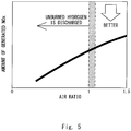
Fig. 5 , when the air ratio is increased, the amount of generated NOx tends to increase. The air ratio is preferably in a range of no lower than 1.0 and no higher than 1.5. The air ratio is preferably 1.0 or higher because, based on calculation, when the air ratio is 1.0 or higher, no unburned hydrogen is discharged. Further, the air ratio is preferably 1.5 or lower because when the air ratio is 1.5 or lower, the combustion does not require a larger amount of air, thus contributing to energy-saving. - Further, as shown in
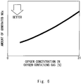
Fig. 6 , when the concentration of oxygen in the oxygen-containing gas is increased, the amount of generated NOx tends to increase. It is preferable that the concentration of oxygen in the oxygen-containing gas be, for example, no lower than 10 vl% and no higher than 21 vl%. The concentration of oxygen in the oxygen-containing gas is preferably 10% or higher because when the connection is 10% or higher, a combustion flame can be stably generated. The concentration of oxygen in the oxygen-containing gas is preferably lower than 21% because when the concentration is lower than 21%, it is lower than the concentration of oxygen in the air, thus making it possible to reduce the amount of generated NOx. - As described above, after the oxygen-containing gas is discharged from the opened
end 2b of theinner tube 2 in the direction along the axis Y1, it proceeds inside of the part of theouter tube 1 that extends beyond the openedend 2b of theinner tube 2 in the direction along the axis Y1. Meanwhile, after the hydrogen gas passes through the space between the innercircumferential surface 1d of theouter tube 1 and the outercircumferential surface 2e of theinner tube 2, it proceeds along the outer periphery of the oxygen-containing gas. In this way, contact between the oxygen-containing gas and the hydrogen gas is suppressed and hence the hydrogen gas is slowly burned. Therefore, it is possible to prevent the temperature of the tubular flame F1 from locally becoming high and thereby to reduce the amount of generated NOx. Further, a flashback phenomenon hardly occurs. - Further, the
nozzle structure 10 includes thegas blowing part 3, and thegas blowing part 3 includes the oxygen-containinggas blowing duct 3a having a circular shape and the hydrogengas blowing duct 3b having an annular shape. Since the oxygen-containinggas blowing duct 3a enables the oxygen-containing gas to be uniformly blown out therefrom in the direction along the axis Y1, a flow of the oxygen-containing gas having a circular cross section is formed. Further, since the hydrogengas blowing duct 3b enables the hydrogen gas to be uniformly blown out therefrom in the direction roughly parallel to the axis Y1, a flow of the hydrogen gas having an annular cross section is formed. Therefore, the hydrogen gas having the annular cross section flows around the outer periphery of the oxygen-containing gas having the circular cross section. Consequently, the mixture of the hydrogen gas and the oxygen-containing gas is further prevented from advancing. Accordingly, it is possible to further prevent the temperature of the tubular flame F1 from locally becoming high and thereby to further reduce the amount of generated NOx. - Next, a modified example of the nozzle structure according to the first embodiment is described with reference to
Figs. 7 and 8 . - As shown in
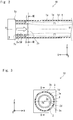
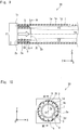
Figs. 7 and 8 , anozzle structure 20 has a configuration similar to that of the nozzle structure 10 (seeFigs. 1 to 3 ), except that thenozzle structure 20 includesfins 4. Thefins 4 are disposed on the outercircumferential surface 2e of theinner tube 2. As shown inFig. 7 , in a section between the openedend 2b of theinner tube 2 and the base-side end part 2c thereof, thefins 4 extend along the axis Y1 of theouter tube 1 while protruding toward theouter tube 1. As shown inFig. 8 , a plurality offins 4 are provided on the outercircumferential surface 2e of theinner tube 2 and are disposed in such a manner that they perpendicularly protrude from the outercircumferential surface 2e in a radial pattern around the axis Y1. In the example of thefins 4 shown inFig. 8 , twelve fins are provided on the outercircumferential surface 2e of theinner tube 2. In the example of thefins 4 shown inFig. 8 , they are arranged around the axis Y1 at angular intervals that are obtained by dividing 360° by twelve, i.e., arranged at intervals of 30°. - Note that the
nozzle structure 20 comprises thefins 4, and thefins 4 guide the hydrogen gas blown out from the hydrogengas blowing duct 3b so that the hydrogen gas is further propelled in a direction roughly parallel to the axis Y1 toward the oneend part 1b of theouter tube 1. Further, thefins 4 prevent the hydrogen gas from flowing in such a manner that it is rotated around the axis Y1. Therefore, the mixture of the hydrogen gas and the oxygen-containing gas is further prevented from advancing. Consequently, it is possible to further prevent the temperature of the tubular flame F1 from locally becoming high and thereby to further reduce the amount of generated NOx. - Next, another modified example of the nozzle structure according to the first embodiment is described with reference to
Figs. 9 and 10 . - As shown in
Figs. 9 and 10 , anozzle structure 30 has a configuration similar to that of the nozzle structure 10 (seeFigs. 1 to 3 ), except that thenozzle structure 30 includesfins 5. Thefins 5 are disposed on the surface of theouter tube 1 that faces theinner tube 2, i.e., disposed on the innercircumferential surface 1d of theouter tube 1. As shown inFig. 9 , in a section between the openedend 2b of theinner tube 2 and the base-side end part 2c thereof, thefins 5 extend in a direction roughly parallel to the axis Y1 of theouter tube 1 while protruding toward theinner tube 2. A plurality offins 5 are provided on the innercircumferential surface 1d of theouter tube 1 and are disposed in such a manner that they perpendicularly protrude from the innercircumferential surface 1d in a radial pattern around the axis Y1. In the example of thefins 5 shown inFigs. 9 and 10 , twelve fins are provided on the innercircumferential surface 1d of theouter tube 1. In the example of thefins 5 shown inFig. 9 , they are arranged around the axis Y1 at angular intervals that are obtained by dividing 360° by twelve, i.e., arranged at intervals of 30°. - Note that the
nozzle structure 30 comprises thefins 5, and thefins 5 guide the hydrogen gas blown out from the hydrogengas blowing duct 3b so that the hydrogen gas is further propelled in a direction roughly parallel to the axis Y1 toward the oneend part 1b of theouter tube 1. Further, thefins 5 prevent the hydrogen gas from flowing in such a manner that it is rotated around the axis Y1. Therefore, the progress of the mixture of the hydrogen gas and the oxygen-containing gas is further suppressed. Consequently, it is possible to further prevent the temperature of the tubular flame F1 from locally becoming high and thereby to further reduce the amount of generated NOx. - Next, a combustion experiment was carried out by using an example of the nozzle structure 10 (see
Figs. 1 to 3 ), and results of measurement in which amounts of generated NOx were measured for different combustion load factors are explained. - Note that in a comparative example 1, a combustion experiment was carried out by using a publicly-known nozzle structure having a configuration different from that of the
nozzle structure 10 and by using a hydrocarbon gas as a fuel gas. This known nozzle structure is commonly used in cases where a hydrocarbon gas is used as a fuel gas. In a comparative example 2, a combustion experiment was carried out by using a publicly-known nozzle structure having a configuration different from that of thenozzle structure 10 and by using a hydrogen gas as a fuel gas. In each of the comparative examples 1 and 2, amounts of generated NOx were measured for different combustion load factors. - As shown in
Fig. 11 , in the example, the amount of generated NOx tends to be constant even when the combustion load factor is increased. In contrast to this, in the comparative examples 1 and 2, the amount of generated NOx tends to increase when the combustion load factor is increased. The amounts of generated NOx in both of the comparative examples 1 and 2 were higher than the amount of generated NOx in the example irrespective of the combustion load factor. In other words, the amount of generated NOx in the example was lower than those in the comparative examples 1 and 2. - Note that the present disclosure is not limited to the above-described embodiments and they can be modified as desired without departing from the spirit of the present disclosure. For example, although the
nozzle structures 20 and 30 (seeFigs. 7 to 10 ) are equipped with thefins fins - From the disclosure thus described, it will be obvious that the embodiments of the disclosure may be varied in many ways. Such variations are not to be regarded as a departure from the spirit and scope of the disclosure, and all such modifications as would be obvious to one skilled in the art are intended for inclusion within the scope of the following claims.
Claims (3)
- A nozzle structure (10, 20, 30) for a hydrogen gas burner apparatus, comprising an outer tube (1) and an inner tube (2) concentrically disposed inside the outer tube (1), wherein
the inner tube (2) is disposed so that an oxygen-containing gas is discharged from an opened end (2b) of the inner tube (2) in an axial direction (Y1), and
the outer tube (1) extends beyond the opened end (2b) of the inner tube (2) in the axial direction (Y1) so that a hydrogen gas passes through a space between an inner circumferential surface (1d) of the outer tube (1) and an outer circumferential surface (2e) of the inner tube (2). - The nozzle structure (10, 20, 30) for a hydrogen gas burner apparatus according to Claim 1, further comprising:an oxygen-containing gas blowing duct (3a) configured to blow out the oxygen-containing gas in the axial direction (Y1) and make the oxygen-containing gas pass through a space inside the inner tube (2); anda hydrogen gas blowing duct (3b) configured to blow out the hydrogen gas into the space between the inner circumferential surface (1d) of the outer tube (1) and the outer circumferential surface (2e) of the inner tube (2) in the axial direction (Y1), and make the hydrogen gas pass through between the inner circumferential surface (1d) of the outer tube (1) and the outer circumferential surface (2e) of the inner tube (2), whereinthe oxygen-containing gas blowing duct (3a) may have a circular shape, andthe hydrogen gas blowing duct (3b) may have an annular shape so as to surround the oxygen-containing gas blowing duct (3a).
- The nozzle structure (10, 20, 30) for a hydrogen gas burner apparatus according to Claim 1 or 2, wherein in a section between the opened end (2b) of the inner tube (2) and a base part thereof, a fin (5) that extends in the axial direction (Y1) while protruding toward the inner tube (2) is provided on the inner circumferential surface (1d) of the outer tube (1), or a fin (4) that extends in the axial direction (Y1) while protruding toward the outer tube (1) is provided on the outer circumferential surface (2e) of the inner tube (2).
Applications Claiming Priority (1)
| Application Number | Priority Date | Filing Date | Title |
|---|---|---|---|
| JP2017169965A JP6863189B2 (en) | 2017-09-05 | 2017-09-05 | Nozzle structure for hydrogen gas burner equipment |
Publications (2)
| Publication Number | Publication Date |
|---|---|
| EP3450843A1 true EP3450843A1 (en) | 2019-03-06 |
| EP3450843B1 EP3450843B1 (en) | 2021-04-28 |
Family
ID=63035943
Family Applications (1)
| Application Number | Title | Priority Date | Filing Date |
|---|---|---|---|
| EP18185028.0A Active EP3450843B1 (en) | 2017-09-05 | 2018-07-23 | Nozzle structure for hydrogen gas burner apparatus |
Country Status (4)
| Country | Link |
|---|---|
| US (2) | US11098893B2 (en) |
| EP (1) | EP3450843B1 (en) |
| JP (1) | JP6863189B2 (en) |
| CN (3) | CN111810949B (en) |
Cited By (3)
| Publication number | Priority date | Publication date | Assignee | Title |
|---|---|---|---|---|
| WO2021233530A1 (en) | 2020-05-19 | 2021-11-25 | Flammatec, Spol. S R.O. | Method and burner of hydrogen combustion in industrial furnace, especially in a glass furnace or a furnace for metal melting, by means of a multi nozzle burner |
| DE102021001419A1 (en) | 2021-03-17 | 2022-09-22 | Messer Austria Gmbh | Burner and method for burning a hydrogen-containing fuel |
| WO2022198328A1 (en) | 2021-03-26 | 2022-09-29 | HYDRO-QUéBEC | Method and system for producing a gas comprising nitrogen (n2) and hydrogen (h2) by combustion of hydrogen in the presence of air |
Families Citing this family (6)
| Publication number | Priority date | Publication date | Assignee | Title |
|---|---|---|---|---|
| EP4158247B1 (en) | 2020-06-29 | 2023-11-01 | AMF Den Boer B.V. | Hydrogen gas burner |
| SE547126C2 (en) | 2021-02-03 | 2025-04-29 | Hybrit Development Ab | Bleed-off gas recovery in a direct reduction process |
| JP2022123674A (en) * | 2021-02-12 | 2022-08-24 | 弘江 川島 | Hydrogen gas combustion device and hydrogen gas combustion system |
| CN113716526B (en) * | 2021-10-11 | 2022-11-15 | 福建福豆新材料有限公司 | Combustion reactor for producing high-purity electronic grade hydrogen bromide and equipment thereof |
| TWI810718B (en) * | 2021-11-22 | 2023-08-01 | 財團法人金屬工業研究發展中心 | Injection system for hydrogen burner |
| DE102022122863A1 (en) * | 2022-09-08 | 2024-03-14 | Albert Hesse Familienstiftung | Thermal process system with a hydrogen-powered heating device, sustainable cremation, CO2-free |
Citations (4)
| Publication number | Priority date | Publication date | Assignee | Title |
|---|---|---|---|---|
| JP2003279001A (en) * | 2002-03-25 | 2003-10-02 | Osaka Gas Co Ltd | Single-end type radiant tube combustion device |
| JP2005188775A (en) | 2003-12-24 | 2005-07-14 | Jfe Steel Kk | Tubular flame burner |
| US20120181355A1 (en) * | 2011-01-17 | 2012-07-19 | General Electric Company | System for flow control in fuel injectors |
| WO2013024783A1 (en) * | 2011-08-17 | 2013-02-21 | 大陽日酸株式会社 | H2 burner and h2 burner combustion method |
Family Cites Families (51)
| Publication number | Priority date | Publication date | Assignee | Title |
|---|---|---|---|---|
| US140606A (en) * | 1873-07-08 | Improvement in metallurgy gas-furnaces | ||
| US1175629A (en) * | 1915-05-15 | 1916-03-14 | Frederick H N Gerwig | Hot-blast-stove appliance. |
| US3339616A (en) * | 1965-06-03 | 1967-09-05 | Chemetron Corp | Apparatus for combustion of fuels and burner therefor |
| US3387784A (en) * | 1966-10-27 | 1968-06-11 | Chemetron Corp | Burner for fluid fuels |
| JPS539531U (en) * | 1976-07-08 | 1978-01-26 | ||
| DE3735002A1 (en) * | 1987-10-16 | 1989-04-27 | Metallgesellschaft Ag | PROCESS FOR REMOVING SULFUR HYDROGEN FROM EXHAUST GAS |
| US5129333A (en) * | 1991-06-24 | 1992-07-14 | Aga Ab | Apparatus and method for recycling waste |
| US5609781A (en) * | 1992-10-23 | 1997-03-11 | Mitsubishi Denki Kabushiki Kaisha | Machining head and laser machining apparatus |
| JPH07260106A (en) * | 1994-03-18 | 1995-10-13 | Hitachi Ltd | Pulverized coal combustion burner and pulverized coal combustion device |
| DE4436908A1 (en) * | 1994-10-15 | 1996-04-18 | Philips Patentverwaltung | Nozzle for a combustion device |
| JP3492099B2 (en) * | 1995-10-03 | 2004-02-03 | 三菱重工業株式会社 | Burner |
| JP2000143205A (en) * | 1998-11-06 | 2000-05-23 | Tokyo Gas Co Ltd | Burner for hydrogen separation type reformer |
| JP3924089B2 (en) * | 1999-04-28 | 2007-06-06 | 株式会社日立製作所 | Pulverized coal burner and combustion apparatus using pulverized coal burner |
| US6113389A (en) * | 1999-06-01 | 2000-09-05 | American Air Liquide, Inc. | Method and system for increasing the efficiency and productivity of a high temperature furnace |
| US6142764A (en) * | 1999-09-02 | 2000-11-07 | Praxair Technology, Inc. | Method for changing the length of a coherent jet |
| ATE278153T1 (en) * | 2000-03-13 | 2004-10-15 | John Zink Co Llc | WALL RADIANT BURNER WITH LOW NOX EMISSIONS |
| EP1179709B1 (en) * | 2000-08-09 | 2005-12-14 | Calsonic Kansei Corporation | Hydrogen combustion heater |
| KR100414668B1 (en) * | 2001-07-21 | 2004-01-07 | 삼성전자주식회사 | Flame stabilizer of burner for flame hydrolysis deposition process |
| ATE338916T1 (en) * | 2002-01-31 | 2006-09-15 | Air Prod & Chem | BURNER FOR PROCESS HEATING WITH VERY LOW NOX EMISSIONS |
| US6773256B2 (en) * | 2002-02-05 | 2004-08-10 | Air Products And Chemicals, Inc. | Ultra low NOx burner for process heating |
| US6886757B2 (en) * | 2002-02-22 | 2005-05-03 | General Motors Corporation | Nozzle assembly for HVOF thermal spray system |
| JP4150968B2 (en) * | 2003-11-10 | 2008-09-17 | 株式会社日立製作所 | Solid fuel burner and combustion method of solid fuel burner |
| US7588074B1 (en) * | 2004-12-21 | 2009-09-15 | Robert Alvin White | In the rate of energy transfer across boundaries |
| JP2007010173A (en) | 2005-06-28 | 2007-01-18 | Tama Tlo Kk | Nozzle burner device and thermal spraying device |
| JP2007162993A (en) * | 2005-12-12 | 2007-06-28 | Toyota Motor Corp | Combustion burner and reformer provided with the same |
| NO324171B1 (en) * | 2006-01-11 | 2007-09-03 | Ntnu Technology Transfer As | Method of combustion of gas, as well as gas burner |
| JP4910129B2 (en) | 2006-04-14 | 2012-04-04 | 株式会社スターエナジー | Long burner |
| CN101568651B (en) * | 2006-12-15 | 2012-06-27 | 普莱克斯技术有限公司 | Injection method for inert gas |
| FR2913097B1 (en) | 2007-02-26 | 2009-04-24 | Inst Francais Du Petrole | POROUS BURNER WITH HYDROGEN WITHOUT PREMIX |
| CN101910723B (en) * | 2007-11-27 | 2013-07-24 | 阿尔斯通技术有限公司 | Device for burning hydrogen in a premix burner |
| KR100901120B1 (en) * | 2008-12-02 | 2009-06-08 | 황부성 | Hydrogen-oxygen mixed gas combustion burner |
| KR101015506B1 (en) * | 2008-12-02 | 2011-02-16 | 삼성전자주식회사 | Fuel Reformer Burners in Fuel Cell Systems |
| US20130032250A1 (en) * | 2010-04-20 | 2013-02-07 | Taiyo Nippon Sanso Corporation | Gas cutting method, gas cutting machine, and cutting tip |
| WO2012042693A1 (en) * | 2010-09-30 | 2012-04-05 | バブコック日立株式会社 | Oxygen combustion system and method for operating same |
| CN103782099B (en) * | 2011-02-16 | 2016-03-16 | 气体产品与化学公司 | The oxygen enrichment of premixed air-gas burner |
| CN202221235U (en) * | 2011-09-21 | 2012-05-16 | 苏州汇科机电设备有限公司 | Heater structure of electronic powder firing furnace |
| JP5897363B2 (en) * | 2012-03-21 | 2016-03-30 | 川崎重工業株式会社 | Pulverized coal biomass mixed burner |
| JP6011073B2 (en) * | 2012-07-02 | 2016-10-19 | 株式会社Ihi | Burner |
| EP3003997B1 (en) | 2013-05-30 | 2021-04-28 | Johns Manville | Submerged combustion burners with mixing improving means for glass melters, and use |
| CN103742913B (en) * | 2014-01-16 | 2015-12-30 | 北京大学 | A kind of direct spray type gas flameless burner |
| KR20150134571A (en) * | 2014-05-22 | 2015-12-02 | 이명재 | Backfire prevention apparatus of injection nozzle for oxyhydrogen gas |
| US9909549B2 (en) * | 2014-10-01 | 2018-03-06 | National Technology & Engineering Solutions Of Sandia, Llc | Ducted fuel injection |
| CN105042591B (en) * | 2015-07-14 | 2017-06-27 | 北京市公用事业科学研究所 | Low NOx gas burners and its gas collocation method |
| US10041666B2 (en) * | 2015-08-27 | 2018-08-07 | Johns Manville | Burner panels including dry-tip burners, submerged combustion melters, and methods |
| US10344971B2 (en) * | 2016-06-13 | 2019-07-09 | Fives North American Combustion, Inc. | Low NOx combustion |
| US10337732B2 (en) * | 2016-08-25 | 2019-07-02 | Johns Manville | Consumable tip burners, submerged combustion melters including same, and methods |
| JP6551375B2 (en) * | 2016-12-07 | 2019-07-31 | トヨタ自動車株式会社 | Hydrogen gas burner structure and hydrogen gas burner apparatus equipped with the same |
| CN107033972A (en) * | 2017-05-09 | 2017-08-11 | 哈尔滨工业大学 | A kind of dry coal powder airflow bed gasification furnace burner with purging gas shielded |
| CN107084390B (en) * | 2017-05-31 | 2019-01-29 | 北京理工大学 | A clean gas-liquid dual-fuel dual-swirl burner |
| JP6891740B2 (en) * | 2017-09-04 | 2021-06-18 | トヨタ自動車株式会社 | Hydrogen gas burner device |
| JP6940338B2 (en) * | 2017-09-04 | 2021-09-29 | トヨタ自動車株式会社 | Nozzle structure for hydrogen gas burner equipment |
-
2017
- 2017-09-05 JP JP2017169965A patent/JP6863189B2/en active Active
-
2018
- 2018-07-23 EP EP18185028.0A patent/EP3450843B1/en active Active
- 2018-08-13 US US16/101,694 patent/US11098893B2/en active Active
- 2018-09-03 CN CN202010564474.4A patent/CN111810949B/en active Active
- 2018-09-03 CN CN201811020789.1A patent/CN109424958B/en active Active
- 2018-09-03 CN CN202010565071.1A patent/CN111810950A/en active Pending
-
2021
- 2021-06-15 US US17/348,161 patent/US20210310651A1/en not_active Abandoned
Patent Citations (4)
| Publication number | Priority date | Publication date | Assignee | Title |
|---|---|---|---|---|
| JP2003279001A (en) * | 2002-03-25 | 2003-10-02 | Osaka Gas Co Ltd | Single-end type radiant tube combustion device |
| JP2005188775A (en) | 2003-12-24 | 2005-07-14 | Jfe Steel Kk | Tubular flame burner |
| US20120181355A1 (en) * | 2011-01-17 | 2012-07-19 | General Electric Company | System for flow control in fuel injectors |
| WO2013024783A1 (en) * | 2011-08-17 | 2013-02-21 | 大陽日酸株式会社 | H2 burner and h2 burner combustion method |
Cited By (6)
| Publication number | Priority date | Publication date | Assignee | Title |
|---|---|---|---|---|
| WO2021233530A1 (en) | 2020-05-19 | 2021-11-25 | Flammatec, Spol. S R.O. | Method and burner of hydrogen combustion in industrial furnace, especially in a glass furnace or a furnace for metal melting, by means of a multi nozzle burner |
| DE102021001419A1 (en) | 2021-03-17 | 2022-09-22 | Messer Austria Gmbh | Burner and method for burning a hydrogen-containing fuel |
| WO2022194991A1 (en) | 2021-03-17 | 2022-09-22 | Messer Austria Gmbh | Burner and process for burning a hydrogen-containing fuel |
| WO2022198328A1 (en) | 2021-03-26 | 2022-09-29 | HYDRO-QUéBEC | Method and system for producing a gas comprising nitrogen (n2) and hydrogen (h2) by combustion of hydrogen in the presence of air |
| CN117255768A (en) * | 2021-03-26 | 2023-12-19 | 海德罗魁北克公司 | Method and system for producing a gas comprising nitrogen (N2) and hydrogen (H2) by combusting hydrogen in the presence of air |
| EP4313848A4 (en) * | 2021-03-26 | 2025-03-05 | Hydro-Québec | METHOD AND SYSTEM FOR PRODUCING A GAS COMPRISING NITROGEN (N2) AND HYDROGEN (H2) BY COMBUSTION OF HYDROGEN IN THE PRESENCE OF AIR |
Also Published As
| Publication number | Publication date |
|---|---|
| JP2019045092A (en) | 2019-03-22 |
| CN111810949B (en) | 2023-01-17 |
| CN111810949A (en) | 2020-10-23 |
| CN109424958A (en) | 2019-03-05 |
| US20210310651A1 (en) | 2021-10-07 |
| CN109424958B (en) | 2021-03-23 |
| JP6863189B2 (en) | 2021-04-21 |
| US11098893B2 (en) | 2021-08-24 |
| CN111810950A (en) | 2020-10-23 |
| US20190072273A1 (en) | 2019-03-07 |
| EP3450843B1 (en) | 2021-04-28 |
Similar Documents
| Publication | Publication Date | Title |
|---|---|---|
| US11098893B2 (en) | Nozzle structure for hydrogen gas burner apparatus | |
| US6752620B2 (en) | Large scale vortex devices for improved burner operation | |
| US5117636A (en) | Low nox emission in gas turbine system | |
| EP0717237B1 (en) | Process and apparatus for burning oxygenic constituents in process gas | |
| US10648662B2 (en) | Nozzle structure for hydrogen gas burner apparatus | |
| US9920927B2 (en) | Low NOx burner | |
| CN1009948B (en) | Restoration heating burner of direct flame type | |
| JP4063216B2 (en) | Tubular flame burner | |
| CN115388406B (en) | Low-emission high-speed burner, flameless combustion device and ignition method thereof | |
| ITTO940510A1 (en) | LIQUID OR GASEOUS FUEL BURNER WITH VERY REDUCED EMISSION OF NITROGEN OXIDES. | |
| CN104180397A (en) | Pre-mixing on-duty nozzle | |
| US9518306B2 (en) | Top-firing hot blast stove | |
| JP4103795B2 (en) | Hot air generator and control method | |
| US12196415B2 (en) | Radiant wall burner | |
| JP7257517B2 (en) | oxygen forehearth burner assembly | |
| JPS6118082B2 (en) | ||
| JP7843528B2 (en) | burner | |
| JPH05302704A (en) | Single-ended radiant tube and combustion method | |
| JP2000314526A (en) | Gas turbine combustor pre-evaporation pre-mix burner and pre-mix burner | |
| EP1136776B1 (en) | Device for injecting solid fuels in atomised form into a cement kiln | |
| JP2021188851A (en) | Burner and fine particle synthesis method using burner | |
| JP2000283422A (en) | Burner device | |
| JPS62196519A (en) | Catalytic burner | |
| WO2000020799A1 (en) | Combustion stabilizing system in a gas burner of low nitrogen oxides emission |
Legal Events
| Date | Code | Title | Description |
|---|---|---|---|
| PUAI | Public reference made under article 153(3) epc to a published international application that has entered the european phase |
Free format text: ORIGINAL CODE: 0009012 |
|
| STAA | Information on the status of an ep patent application or granted ep patent |
Free format text: STATUS: REQUEST FOR EXAMINATION WAS MADE |
|
| 17P | Request for examination filed |
Effective date: 20180723 |
|
| AK | Designated contracting states |
Kind code of ref document: A1 Designated state(s): AL AT BE BG CH CY CZ DE DK EE ES FI FR GB GR HR HU IE IS IT LI LT LU LV MC MK MT NL NO PL PT RO RS SE SI SK SM TR |
|
| AX | Request for extension of the european patent |
Extension state: BA ME |
|
| STAA | Information on the status of an ep patent application or granted ep patent |
Free format text: STATUS: EXAMINATION IS IN PROGRESS |
|
| 17Q | First examination report despatched |
Effective date: 20200330 |
|
| GRAP | Despatch of communication of intention to grant a patent |
Free format text: ORIGINAL CODE: EPIDOSNIGR1 |
|
| STAA | Information on the status of an ep patent application or granted ep patent |
Free format text: STATUS: GRANT OF PATENT IS INTENDED |
|
| INTG | Intention to grant announced |
Effective date: 20201215 |
|
| GRAS | Grant fee paid |
Free format text: ORIGINAL CODE: EPIDOSNIGR3 |
|
| GRAA | (expected) grant |
Free format text: ORIGINAL CODE: 0009210 |
|
| STAA | Information on the status of an ep patent application or granted ep patent |
Free format text: STATUS: THE PATENT HAS BEEN GRANTED |
|
| AK | Designated contracting states |
Kind code of ref document: B1 Designated state(s): AL AT BE BG CH CY CZ DE DK EE ES FI FR GB GR HR HU IE IS IT LI LT LU LV MC MK MT NL NO PL PT RO RS SE SI SK SM TR |
|
| REG | Reference to a national code |
Ref country code: GB Ref legal event code: FG4D |
|
| REG | Reference to a national code |
Ref country code: CH Ref legal event code: EP |
|
| REG | Reference to a national code |
Ref country code: DE Ref legal event code: R096 Ref document number: 602018016094 Country of ref document: DE |
|
| REG | Reference to a national code |
Ref country code: AT Ref legal event code: REF Ref document number: 1387459 Country of ref document: AT Kind code of ref document: T Effective date: 20210515 |
|
| REG | Reference to a national code |
Ref country code: IE Ref legal event code: FG4D |
|
| REG | Reference to a national code |
Ref country code: LT Ref legal event code: MG9D |
|
| REG | Reference to a national code |
Ref country code: AT Ref legal event code: MK05 Ref document number: 1387459 Country of ref document: AT Kind code of ref document: T Effective date: 20210428 |
|
| PG25 | Lapsed in a contracting state [announced via postgrant information from national office to epo] |
Ref country code: HR Free format text: LAPSE BECAUSE OF FAILURE TO SUBMIT A TRANSLATION OF THE DESCRIPTION OR TO PAY THE FEE WITHIN THE PRESCRIBED TIME-LIMIT Effective date: 20210428 Ref country code: LT Free format text: LAPSE BECAUSE OF FAILURE TO SUBMIT A TRANSLATION OF THE DESCRIPTION OR TO PAY THE FEE WITHIN THE PRESCRIBED TIME-LIMIT Effective date: 20210428 Ref country code: FI Free format text: LAPSE BECAUSE OF FAILURE TO SUBMIT A TRANSLATION OF THE DESCRIPTION OR TO PAY THE FEE WITHIN THE PRESCRIBED TIME-LIMIT Effective date: 20210428 Ref country code: AT Free format text: LAPSE BECAUSE OF FAILURE TO SUBMIT A TRANSLATION OF THE DESCRIPTION OR TO PAY THE FEE WITHIN THE PRESCRIBED TIME-LIMIT Effective date: 20210428 Ref country code: BG Free format text: LAPSE BECAUSE OF FAILURE TO SUBMIT A TRANSLATION OF THE DESCRIPTION OR TO PAY THE FEE WITHIN THE PRESCRIBED TIME-LIMIT Effective date: 20210728 Ref country code: NL Free format text: LAPSE BECAUSE OF FAILURE TO SUBMIT A TRANSLATION OF THE DESCRIPTION OR TO PAY THE FEE WITHIN THE PRESCRIBED TIME-LIMIT Effective date: 20210428 |
|
| PG25 | Lapsed in a contracting state [announced via postgrant information from national office to epo] |
Ref country code: LV Free format text: LAPSE BECAUSE OF FAILURE TO SUBMIT A TRANSLATION OF THE DESCRIPTION OR TO PAY THE FEE WITHIN THE PRESCRIBED TIME-LIMIT Effective date: 20210428 Ref country code: NO Free format text: LAPSE BECAUSE OF FAILURE TO SUBMIT A TRANSLATION OF THE DESCRIPTION OR TO PAY THE FEE WITHIN THE PRESCRIBED TIME-LIMIT Effective date: 20210728 Ref country code: PL Free format text: LAPSE BECAUSE OF FAILURE TO SUBMIT A TRANSLATION OF THE DESCRIPTION OR TO PAY THE FEE WITHIN THE PRESCRIBED TIME-LIMIT Effective date: 20210428 Ref country code: PT Free format text: LAPSE BECAUSE OF FAILURE TO SUBMIT A TRANSLATION OF THE DESCRIPTION OR TO PAY THE FEE WITHIN THE PRESCRIBED TIME-LIMIT Effective date: 20210830 Ref country code: RS Free format text: LAPSE BECAUSE OF FAILURE TO SUBMIT A TRANSLATION OF THE DESCRIPTION OR TO PAY THE FEE WITHIN THE PRESCRIBED TIME-LIMIT Effective date: 20210428 Ref country code: SE Free format text: LAPSE BECAUSE OF FAILURE TO SUBMIT A TRANSLATION OF THE DESCRIPTION OR TO PAY THE FEE WITHIN THE PRESCRIBED TIME-LIMIT Effective date: 20210428 Ref country code: IS Free format text: LAPSE BECAUSE OF FAILURE TO SUBMIT A TRANSLATION OF THE DESCRIPTION OR TO PAY THE FEE WITHIN THE PRESCRIBED TIME-LIMIT Effective date: 20210828 Ref country code: GR Free format text: LAPSE BECAUSE OF FAILURE TO SUBMIT A TRANSLATION OF THE DESCRIPTION OR TO PAY THE FEE WITHIN THE PRESCRIBED TIME-LIMIT Effective date: 20210729 |
|
| REG | Reference to a national code |
Ref country code: NL Ref legal event code: MP Effective date: 20210428 |
|
| PG25 | Lapsed in a contracting state [announced via postgrant information from national office to epo] |
Ref country code: EE Free format text: LAPSE BECAUSE OF FAILURE TO SUBMIT A TRANSLATION OF THE DESCRIPTION OR TO PAY THE FEE WITHIN THE PRESCRIBED TIME-LIMIT Effective date: 20210428 Ref country code: ES Free format text: LAPSE BECAUSE OF FAILURE TO SUBMIT A TRANSLATION OF THE DESCRIPTION OR TO PAY THE FEE WITHIN THE PRESCRIBED TIME-LIMIT Effective date: 20210428 Ref country code: SK Free format text: LAPSE BECAUSE OF FAILURE TO SUBMIT A TRANSLATION OF THE DESCRIPTION OR TO PAY THE FEE WITHIN THE PRESCRIBED TIME-LIMIT Effective date: 20210428 Ref country code: SM Free format text: LAPSE BECAUSE OF FAILURE TO SUBMIT A TRANSLATION OF THE DESCRIPTION OR TO PAY THE FEE WITHIN THE PRESCRIBED TIME-LIMIT Effective date: 20210428 Ref country code: DK Free format text: LAPSE BECAUSE OF FAILURE TO SUBMIT A TRANSLATION OF THE DESCRIPTION OR TO PAY THE FEE WITHIN THE PRESCRIBED TIME-LIMIT Effective date: 20210428 Ref country code: CZ Free format text: LAPSE BECAUSE OF FAILURE TO SUBMIT A TRANSLATION OF THE DESCRIPTION OR TO PAY THE FEE WITHIN THE PRESCRIBED TIME-LIMIT Effective date: 20210428 Ref country code: RO Free format text: LAPSE BECAUSE OF FAILURE TO SUBMIT A TRANSLATION OF THE DESCRIPTION OR TO PAY THE FEE WITHIN THE PRESCRIBED TIME-LIMIT Effective date: 20210428 |
|
| REG | Reference to a national code |
Ref country code: DE Ref legal event code: R097 Ref document number: 602018016094 Country of ref document: DE |
|
| REG | Reference to a national code |
Ref country code: CH Ref legal event code: PL |
|
| PLBE | No opposition filed within time limit |
Free format text: ORIGINAL CODE: 0009261 |
|
| STAA | Information on the status of an ep patent application or granted ep patent |
Free format text: STATUS: NO OPPOSITION FILED WITHIN TIME LIMIT |
|
| PG25 | Lapsed in a contracting state [announced via postgrant information from national office to epo] |
Ref country code: MC Free format text: LAPSE BECAUSE OF FAILURE TO SUBMIT A TRANSLATION OF THE DESCRIPTION OR TO PAY THE FEE WITHIN THE PRESCRIBED TIME-LIMIT Effective date: 20210428 |
|
| REG | Reference to a national code |
Ref country code: BE Ref legal event code: MM Effective date: 20210731 |
|
| 26N | No opposition filed |
Effective date: 20220131 |
|
| PG25 | Lapsed in a contracting state [announced via postgrant information from national office to epo] |
Ref country code: LI Free format text: LAPSE BECAUSE OF NON-PAYMENT OF DUE FEES Effective date: 20210731 Ref country code: CH Free format text: LAPSE BECAUSE OF NON-PAYMENT OF DUE FEES Effective date: 20210731 |
|
| PG25 | Lapsed in a contracting state [announced via postgrant information from national office to epo] |
Ref country code: IS Free format text: LAPSE BECAUSE OF FAILURE TO SUBMIT A TRANSLATION OF THE DESCRIPTION OR TO PAY THE FEE WITHIN THE PRESCRIBED TIME-LIMIT Effective date: 20210828 Ref country code: LU Free format text: LAPSE BECAUSE OF NON-PAYMENT OF DUE FEES Effective date: 20210723 Ref country code: AL Free format text: LAPSE BECAUSE OF FAILURE TO SUBMIT A TRANSLATION OF THE DESCRIPTION OR TO PAY THE FEE WITHIN THE PRESCRIBED TIME-LIMIT Effective date: 20210428 |
|
| PG25 | Lapsed in a contracting state [announced via postgrant information from national office to epo] |
Ref country code: IT Free format text: LAPSE BECAUSE OF FAILURE TO SUBMIT A TRANSLATION OF THE DESCRIPTION OR TO PAY THE FEE WITHIN THE PRESCRIBED TIME-LIMIT Effective date: 20210428 Ref country code: IE Free format text: LAPSE BECAUSE OF NON-PAYMENT OF DUE FEES Effective date: 20210723 Ref country code: BE Free format text: LAPSE BECAUSE OF NON-PAYMENT OF DUE FEES Effective date: 20210731 |
|
| P01 | Opt-out of the competence of the unified patent court (upc) registered |
Effective date: 20230427 |
|
| REG | Reference to a national code |
Ref country code: DE Ref legal event code: R084 Ref document number: 602018016094 Country of ref document: DE |
|
| PG25 | Lapsed in a contracting state [announced via postgrant information from national office to epo] |
Ref country code: CY Free format text: LAPSE BECAUSE OF FAILURE TO SUBMIT A TRANSLATION OF THE DESCRIPTION OR TO PAY THE FEE WITHIN THE PRESCRIBED TIME-LIMIT Effective date: 20210428 |
|
| PG25 | Lapsed in a contracting state [announced via postgrant information from national office to epo] |
Ref country code: HU Free format text: LAPSE BECAUSE OF FAILURE TO SUBMIT A TRANSLATION OF THE DESCRIPTION OR TO PAY THE FEE WITHIN THE PRESCRIBED TIME-LIMIT; INVALID AB INITIO Effective date: 20180723 |
|
| REG | Reference to a national code |
Ref country code: GB Ref legal event code: 746 Effective date: 20230815 |
|
| PG25 | Lapsed in a contracting state [announced via postgrant information from national office to epo] |
Ref country code: MK Free format text: LAPSE BECAUSE OF FAILURE TO SUBMIT A TRANSLATION OF THE DESCRIPTION OR TO PAY THE FEE WITHIN THE PRESCRIBED TIME-LIMIT Effective date: 20210428 |
|
| PG25 | Lapsed in a contracting state [announced via postgrant information from national office to epo] |
Ref country code: TR Free format text: LAPSE BECAUSE OF FAILURE TO SUBMIT A TRANSLATION OF THE DESCRIPTION OR TO PAY THE FEE WITHIN THE PRESCRIBED TIME-LIMIT Effective date: 20210428 |
|
| PG25 | Lapsed in a contracting state [announced via postgrant information from national office to epo] |
Ref country code: MT Free format text: LAPSE BECAUSE OF FAILURE TO SUBMIT A TRANSLATION OF THE DESCRIPTION OR TO PAY THE FEE WITHIN THE PRESCRIBED TIME-LIMIT Effective date: 20210428 |
|
| PGFP | Annual fee paid to national office [announced via postgrant information from national office to epo] |
Ref country code: GB Payment date: 20250529 Year of fee payment: 8 |
|
| PGFP | Annual fee paid to national office [announced via postgrant information from national office to epo] |
Ref country code: FR Payment date: 20250610 Year of fee payment: 8 |
|
| PGFP | Annual fee paid to national office [announced via postgrant information from national office to epo] |
Ref country code: DE Payment date: 20250528 Year of fee payment: 8 |