EP3450831A1 - Lighting device for vehicle - Google Patents
Lighting device for vehicle Download PDFInfo
- Publication number
- EP3450831A1 EP3450831A1 EP18191516.6A EP18191516A EP3450831A1 EP 3450831 A1 EP3450831 A1 EP 3450831A1 EP 18191516 A EP18191516 A EP 18191516A EP 3450831 A1 EP3450831 A1 EP 3450831A1
- Authority
- EP
- European Patent Office
- Prior art keywords
- light
- vehicle
- lighting device
- projecting lens
- shading member
- Prior art date
- Legal status (The legal status is an assumption and is not a legal conclusion. Google has not performed a legal analysis and makes no representation as to the accuracy of the status listed.)
- Withdrawn
Links
- 230000002093 peripheral effect Effects 0.000 claims description 11
- 238000010586 diagram Methods 0.000 description 11
- 238000003466 welding Methods 0.000 description 4
- 230000014509 gene expression Effects 0.000 description 3
- 230000003287 optical effect Effects 0.000 description 3
- 230000001154 acute effect Effects 0.000 description 2
- 230000000052 comparative effect Effects 0.000 description 2
- 238000001514 detection method Methods 0.000 description 2
- 238000005286 illumination Methods 0.000 description 2
- 230000004075 alteration Effects 0.000 description 1
- 238000012986 modification Methods 0.000 description 1
- 230000004048 modification Effects 0.000 description 1
- 239000011347 resin Substances 0.000 description 1
- 229920005989 resin Polymers 0.000 description 1
- 239000004065 semiconductor Substances 0.000 description 1
- 238000000926 separation method Methods 0.000 description 1
Images





Classifications
-
- F—MECHANICAL ENGINEERING; LIGHTING; HEATING; WEAPONS; BLASTING
- F21—LIGHTING
- F21S—NON-PORTABLE LIGHTING DEVICES; SYSTEMS THEREOF; VEHICLE LIGHTING DEVICES SPECIALLY ADAPTED FOR VEHICLE EXTERIORS
- F21S41/00—Illuminating devices specially adapted for vehicle exteriors, e.g. headlamps
- F21S41/30—Illuminating devices specially adapted for vehicle exteriors, e.g. headlamps characterised by reflectors
- F21S41/32—Optical layout thereof
- F21S41/321—Optical layout thereof the reflector being a surface of revolution or a planar surface, e.g. truncated
-
- F—MECHANICAL ENGINEERING; LIGHTING; HEATING; WEAPONS; BLASTING
- F21—LIGHTING
- F21S—NON-PORTABLE LIGHTING DEVICES; SYSTEMS THEREOF; VEHICLE LIGHTING DEVICES SPECIALLY ADAPTED FOR VEHICLE EXTERIORS
- F21S41/00—Illuminating devices specially adapted for vehicle exteriors, e.g. headlamps
- F21S41/20—Illuminating devices specially adapted for vehicle exteriors, e.g. headlamps characterised by refractors, transparent cover plates, light guides or filters
- F21S41/25—Projection lenses
-
- B—PERFORMING OPERATIONS; TRANSPORTING
- B60—VEHICLES IN GENERAL
- B60Q—ARRANGEMENT OF SIGNALLING OR LIGHTING DEVICES, THE MOUNTING OR SUPPORTING THEREOF OR CIRCUITS THEREFOR, FOR VEHICLES IN GENERAL
- B60Q1/00—Arrangement of optical signalling or lighting devices, the mounting or supporting thereof or circuits therefor
- B60Q1/02—Arrangement of optical signalling or lighting devices, the mounting or supporting thereof or circuits therefor the devices being primarily intended to illuminate the way ahead or to illuminate other areas of way or environments
- B60Q1/04—Arrangement of optical signalling or lighting devices, the mounting or supporting thereof or circuits therefor the devices being primarily intended to illuminate the way ahead or to illuminate other areas of way or environments the devices being headlights
- B60Q1/18—Arrangement of optical signalling or lighting devices, the mounting or supporting thereof or circuits therefor the devices being primarily intended to illuminate the way ahead or to illuminate other areas of way or environments the devices being headlights being additional front lights
-
- F—MECHANICAL ENGINEERING; LIGHTING; HEATING; WEAPONS; BLASTING
- F21—LIGHTING
- F21S—NON-PORTABLE LIGHTING DEVICES; SYSTEMS THEREOF; VEHICLE LIGHTING DEVICES SPECIALLY ADAPTED FOR VEHICLE EXTERIORS
- F21S41/00—Illuminating devices specially adapted for vehicle exteriors, e.g. headlamps
- F21S41/10—Illuminating devices specially adapted for vehicle exteriors, e.g. headlamps characterised by the light source
- F21S41/14—Illuminating devices specially adapted for vehicle exteriors, e.g. headlamps characterised by the light source characterised by the type of light source
- F21S41/141—Light emitting diodes [LED]
- F21S41/147—Light emitting diodes [LED] the main emission direction of the LED being angled to the optical axis of the illuminating device
- F21S41/148—Light emitting diodes [LED] the main emission direction of the LED being angled to the optical axis of the illuminating device the main emission direction of the LED being perpendicular to the optical axis
-
- F—MECHANICAL ENGINEERING; LIGHTING; HEATING; WEAPONS; BLASTING
- F21—LIGHTING
- F21S—NON-PORTABLE LIGHTING DEVICES; SYSTEMS THEREOF; VEHICLE LIGHTING DEVICES SPECIALLY ADAPTED FOR VEHICLE EXTERIORS
- F21S41/00—Illuminating devices specially adapted for vehicle exteriors, e.g. headlamps
- F21S41/20—Illuminating devices specially adapted for vehicle exteriors, e.g. headlamps characterised by refractors, transparent cover plates, light guides or filters
- F21S41/25—Projection lenses
- F21S41/255—Lenses with a front view of circular or truncated circular outline
-
- F—MECHANICAL ENGINEERING; LIGHTING; HEATING; WEAPONS; BLASTING
- F21—LIGHTING
- F21S—NON-PORTABLE LIGHTING DEVICES; SYSTEMS THEREOF; VEHICLE LIGHTING DEVICES SPECIALLY ADAPTED FOR VEHICLE EXTERIORS
- F21S41/00—Illuminating devices specially adapted for vehicle exteriors, e.g. headlamps
- F21S41/40—Illuminating devices specially adapted for vehicle exteriors, e.g. headlamps characterised by screens, non-reflecting members, light-shielding members or fixed shades
- F21S41/43—Illuminating devices specially adapted for vehicle exteriors, e.g. headlamps characterised by screens, non-reflecting members, light-shielding members or fixed shades characterised by the shape thereof
-
- F—MECHANICAL ENGINEERING; LIGHTING; HEATING; WEAPONS; BLASTING
- F21—LIGHTING
- F21S—NON-PORTABLE LIGHTING DEVICES; SYSTEMS THEREOF; VEHICLE LIGHTING DEVICES SPECIALLY ADAPTED FOR VEHICLE EXTERIORS
- F21S41/00—Illuminating devices specially adapted for vehicle exteriors, e.g. headlamps
- F21S41/60—Illuminating devices specially adapted for vehicle exteriors, e.g. headlamps characterised by a variable light distribution
- F21S41/65—Illuminating devices specially adapted for vehicle exteriors, e.g. headlamps characterised by a variable light distribution by acting on light sources
- F21S41/657—Illuminating devices specially adapted for vehicle exteriors, e.g. headlamps characterised by a variable light distribution by acting on light sources by moving light sources
-
- F—MECHANICAL ENGINEERING; LIGHTING; HEATING; WEAPONS; BLASTING
- F21—LIGHTING
- F21V—FUNCTIONAL FEATURES OR DETAILS OF LIGHTING DEVICES OR SYSTEMS THEREOF; STRUCTURAL COMBINATIONS OF LIGHTING DEVICES WITH OTHER ARTICLES, NOT OTHERWISE PROVIDED FOR
- F21V14/00—Controlling the distribution of the light emitted by adjustment of elements
- F21V14/06—Controlling the distribution of the light emitted by adjustment of elements by movement of refractors
-
- F—MECHANICAL ENGINEERING; LIGHTING; HEATING; WEAPONS; BLASTING
- F21—LIGHTING
- F21V—FUNCTIONAL FEATURES OR DETAILS OF LIGHTING DEVICES OR SYSTEMS THEREOF; STRUCTURAL COMBINATIONS OF LIGHTING DEVICES WITH OTHER ARTICLES, NOT OTHERWISE PROVIDED FOR
- F21V33/00—Structural combinations of lighting devices with other articles, not otherwise provided for
- F21V33/0004—Personal or domestic articles
- F21V33/0052—Audio or video equipment, e.g. televisions, telephones, cameras or computers; Remote control devices therefor
-
- F—MECHANICAL ENGINEERING; LIGHTING; HEATING; WEAPONS; BLASTING
- F21—LIGHTING
- F21V—FUNCTIONAL FEATURES OR DETAILS OF LIGHTING DEVICES OR SYSTEMS THEREOF; STRUCTURAL COMBINATIONS OF LIGHTING DEVICES WITH OTHER ARTICLES, NOT OTHERWISE PROVIDED FOR
- F21V7/00—Reflectors for light sources
- F21V7/04—Optical design
-
- B—PERFORMING OPERATIONS; TRANSPORTING
- B60—VEHICLES IN GENERAL
- B60Q—ARRANGEMENT OF SIGNALLING OR LIGHTING DEVICES, THE MOUNTING OR SUPPORTING THEREOF OR CIRCUITS THEREFOR, FOR VEHICLES IN GENERAL
- B60Q1/00—Arrangement of optical signalling or lighting devices, the mounting or supporting thereof or circuits therefor
- B60Q1/02—Arrangement of optical signalling or lighting devices, the mounting or supporting thereof or circuits therefor the devices being primarily intended to illuminate the way ahead or to illuminate other areas of way or environments
-
- B—PERFORMING OPERATIONS; TRANSPORTING
- B60—VEHICLES IN GENERAL
- B60Q—ARRANGEMENT OF SIGNALLING OR LIGHTING DEVICES, THE MOUNTING OR SUPPORTING THEREOF OR CIRCUITS THEREFOR, FOR VEHICLES IN GENERAL
- B60Q2300/00—Indexing codes for automatically adjustable headlamps or automatically dimmable headlamps
- B60Q2300/40—Indexing codes relating to other road users or special conditions
- B60Q2300/45—Special conditions, e.g. pedestrians, road signs or potential dangers
-
- F—MECHANICAL ENGINEERING; LIGHTING; HEATING; WEAPONS; BLASTING
- F21—LIGHTING
- F21S—NON-PORTABLE LIGHTING DEVICES; SYSTEMS THEREOF; VEHICLE LIGHTING DEVICES SPECIALLY ADAPTED FOR VEHICLE EXTERIORS
- F21S41/00—Illuminating devices specially adapted for vehicle exteriors, e.g. headlamps
- F21S41/30—Illuminating devices specially adapted for vehicle exteriors, e.g. headlamps characterised by reflectors
- F21S41/32—Optical layout thereof
- F21S41/36—Combinations of two or more separate reflectors
- F21S41/365—Combinations of two or more separate reflectors successively reflecting the light
-
- F—MECHANICAL ENGINEERING; LIGHTING; HEATING; WEAPONS; BLASTING
- F21—LIGHTING
- F21W—INDEXING SCHEME ASSOCIATED WITH SUBCLASSES F21K, F21L, F21S and F21V, RELATING TO USES OR APPLICATIONS OF LIGHTING DEVICES OR SYSTEMS
- F21W2102/00—Exterior vehicle lighting devices for illuminating purposes
- F21W2102/10—Arrangement or contour of the emitted light
- F21W2102/13—Arrangement or contour of the emitted light for high-beam region or low-beam region
-
- F—MECHANICAL ENGINEERING; LIGHTING; HEATING; WEAPONS; BLASTING
- F21—LIGHTING
- F21Y—INDEXING SCHEME ASSOCIATED WITH SUBCLASSES F21K, F21L, F21S and F21V, RELATING TO THE FORM OR THE KIND OF THE LIGHT SOURCES OR OF THE COLOUR OF THE LIGHT EMITTED
- F21Y2115/00—Light-generating elements of semiconductor light sources
- F21Y2115/10—Light-emitting diodes [LED]
Definitions
- the present disclosure relates to a lighting device for a vehicle.
- a front lighting device for a vehicle has been proposed (for example, see Japanese Patent Application Laid-Open ( JP-A) No. 2009-220631 (Patent Reference 1)) in which an illumination region of light illuminated from a light source is controlled by altering the position of a shading member such that the light is illuminated at a pedestrian walking at a roadside.
- JP-A Japanese Patent Application Laid-Open
- Patent Reference 1 Patent Reference 1
- an object of the present disclosure is to provide a lighting device for a vehicle that may improve a usage efficiency of light illuminated from a light source.
- a lighting device for a vehicle includes: a light source that illuminates light; a reflecting surface that reflects light illuminated from the light source and causes the light to converge; a shading member including an aperture portion at which the light reflected and caused to converge by the reflecting surface is made incident; and a projecting lens at which light that has passed through the aperture portion of the shading member is incident, the projecting lens emitting the light toward a target.
- the light illuminated from the light source is reflected and converged by the reflecting surface, and is made incident on the aperture portion of the shading member. Therefore, the usage efficiency of the light illuminated from the light source is improved compared to a structure in which light that is illuminated from a light source and reflected by a reflecting surface is not converged on an aperture portion.
- the projecting lens includes plural focusing lenses.
- the projecting lens is constituted by the plural focusing lenses. Therefore, the projecting lens illuminates the light onto a target more distinctly than if the projecting lens were constituted by a single lens.
- a light incidence direction downstream side of a peripheral edge portion structuring the aperture portion of the shading member is formed in an acute-angled shape in cross section.
- the light incidence direction downstream side of the peripheral edge portion structuring the aperture portion of the shading member is formed in the acute-angled shape in cross section. Consequently, there is no risk of light that is reflected at a region opposing the peripheral edge portion being shaded by the peripheral edge portion, in contrast to a structure in which the light incidence direction downstream side of the peripheral edge portion is formed in a rectilinear shape in cross section.
- losses of light illuminated from the light source are suppressed further.
- the shading member is formed integrally with a holder that retains the projecting lens.
- the shading member is formed integrally with the holder that retains the projecting lens. Therefore, in comparison with a structure in which the shading member is a separate body from a holder retaining the projecting lens, both a number of components is reduced and positional offsets between the projecting lens and the aperture portion of the shading member are suppressed.
- the lighting device for a vehicle according to any one of the first to fourth aspects further includes: a recognition unit that recognizes the target; and an actuator that, on the basis of results of recognition by the recognition unit, controls the projecting lens such that the light emitted therefrom illuminates the target.
- an actuator controls the projecting lens such that the light emitted therefrom illuminates the target. Therefore, the light is illuminated at the target more efficiently than in a configuration in which the recognition unit and the actuator are not provided.
- the usage efficiency of light illuminated from the light source may be improved.
- light may be illuminated at the target more distinctly.
- losses of light illuminated from the light source may be suppressed further.
- a number of components may be reduced, in addition to which positional offsets between the projecting lens and the aperture portion of the shading member may be suppressed.
- the light may be illuminated at the target efficiently.
- the arrow UP that is shown where appropriate in the drawings indicates a vehicle upper direction
- the arrow FR indicates a vehicle front direction
- the arrow LH indicates a vehicle left direction.
- a vehicle 12 is equipped with a pair of headlamp units 14 at left and right, for assuring a field of view at the front side of the vehicle 12. That is, a headlamp unit 14R is disposed at a right side front end portion of the vehicle 12, and a headlamp unit 14L is disposed at a left side front end portion of the vehicle 12.
- Each of the headlamp unit 14R and the headlamp unit 14L includes a low beam unit 16 that structures a vehicle width direction outer side portion thereof and a high beam unit 18 that structures a vehicle width direction inner side portion.
- the headlamp unit 14R and headlamp unit 14L are formed with left-right symmetry in the vehicle width direction.
- the low beam unit 16 is structured so as to illuminate light (visible light) onto a low beam light distribution area of a road surface to the front side of the vehicle 12.
- the high beam unit 18 illuminates light (visible light) at a high beam light distribution area, which is diagonally to the upper-front side relative to the low beam light distribution area illuminated by the low beam unit 16.
- a lighting device for a vehicle 10 according to the present exemplary embodiments is provided at the vehicle width direction outer side of the low beam unit 16.
- the lighting device for a vehicle 10 is equipped with a light source 20 and a reflecting member 24.
- the light source 20 illuminates light (visible light).
- the reflecting member 24 includes a reflecting surface 26 with a concave surface shape that reflects the light illuminated from the light source 20 and causes the light to converge.
- the lighting device for a vehicle 10 is also equipped with a shading member 30 and a projecting lens 34.
- the shading member 30 includes an aperture portion 32, at which the light reflected and converged by the reflecting surface 26 is incident.
- the projecting lens 34 emits light that has passed through the aperture portion 32 of the shading member 30 and is incident on the projecting lens 34 toward a target (for example, a pedestrian walking at a
- the pedestrian P a bicycle running at a roadside or the like that is at risk of collision with the vehicle 12, which target is below referred to as "the pedestrian P"; see Fig. 5 ).
- the light source 20 is a high-brightness light source such as a light-emitting diode (LED), a semiconductor laser (a laser diode (LD)) or the like.
- the light source 20 is provided on a circuit board 22 that is electronically connected with a control section 50 (see Fig. 4 ).
- the reflecting member 24 is integrally provided on the circuit board 22 at a rear portion thereof, at a predetermined inclination angle with respect to the circuit board 22 (in Fig. 2 , the reflecting member 24 is depicted as being separated from the circuit board 22).
- the reflecting member 24 is formed in a curved surface shape that bulges toward the rear side.
- a reflecting mirror 25 with a mirror finish is provided at an inner face (front face) of the reflecting member 24.
- a surface (front face) of the reflecting mirror 25 serves as the reflecting surface 26.
- the reflecting member 24 of the present exemplary embodiment serves as a concave reflecting mirror (a reflector).
- the reflecting member 24 apart from the reflecting mirror 25 is fabricated of resin.
- Light V that is illuminated from the light source 20 is both reflected by the reflecting surface 26 and converged toward the aperture portion 32 of the shading member 30 by the reflecting surface 26.
- a front face 34A of the projecting lens 34 is formed in a curved surface shape that bulges toward the front side, and a rear face 34B of the projecting lens 34 is formed in a planar surface shape.
- a protruding portion 35 that protrudes to the diametric direction outer side in a concentric circular shape is integrally formed (in the circumferential direction) along the whole circumference of the projecting lens 34 at a rear side periphery edge portion of the projecting lens 34.
- the protruding portion 35 is joined by laser welding to a front end portion (below referred to as a seat face) 28A of a holder 28.
- the holder 28 is formed in a substantially circular tube shape with an optical axis direction in the front-and-rear direction.
- the protruding portion 35 is adhered (welded) to the seat face 28A of the holder 28 by the protruding portion 35 being abutted against the seat face 28A of the holder 28, a laser beam (not shown in the drawings) illuminated from the front side passing through the protruding portion 35, and the laser beam fusing the seat face 28A of the holder 28.
- a front portion aperture of the holder 28 is closed off by the projecting lens 34.
- the rear face 34B of the projecting lens 34 may be formed in a curved surface shape bulging toward the rear side.
- the projecting lens 34 is configured such that light V that passes through the aperture portion 32 of the shading member 30 and is incident on the rear face 34B is made parallel by being transmitted from the rear face 34B to the front face 34A of the projecting lens 34, and is emitted from the front face 34A.
- light (visible light) V that is parallel light is emitted to the front side of the vehicle 12.
- the shading member 30 is attached to a rear end portion of the holder 28.
- the shading member 30 is formed in a rectangular flat plate shape, the lengths of the diagonals of which are less than an internal diameter of the holder 28.
- An aperture 28B with a rectangular shape similar to that of the shading member 30 is formed at a rear end portion of the holder 28. That is, the rectangular-shaped aperture 28B of the holder 28 is closed off by the shading member 30.
- the aperture portion 32 is formed in a slit shape whose length direction is in the vertical direction at a substantially central portion of the shading member 30.
- the light (visible light) V that has been reflected and converged by the reflecting surface 26 of the reflecting member 24 passes through the aperture portion 32, and the light (visible light) V that has passed through the aperture portion 32 is incident on the rear face 34B of the projecting lens 34.
- the lighting device for a vehicle 10 includes a camera (including an image sensor) 52 and a swivel motor 54 that serves as an actuator.
- the camera 52 serves as a recognition unit that recognizes the pedestrian P as a target.
- the swivel motor 54 controls an orientation of the projecting lens 34 such that the light (visible light) V emitted from the projecting lens 34 is illuminated at the pedestrian P.
- the swivel motor 54 is provided at the lower side of the holder 28 and turns the holder 28, and thus the projecting lens 34, in a left-and-right direction about a rotation axis in the vertical direction.
- the light source 20, swivel motor 54 and camera 52 of the lighting device for a vehicle 10 are each electronically connected with the control section 50.
- the lighting device for a vehicle 10 may illuminate the light (visible light) V toward at least the legs of the pedestrian P who is (walking at the roadside) at risk of collision with the vehicle 12, by the control section 50 causing the light source 20 of the lighting device for a vehicle 10 to light up and driving the swivel motor 54 (turning the holder 28).
- the control section 50 causes the light source 20 of the lighting device for a vehicle 10 to light up, controls the swivel motor 54, and turns the holder 28, and thus the projecting lens 34, in the leftward direction.
- the light (visible light) V passing through the projecting lens 34 from the rear to the front is illuminated at the pedestrian P.
- the light (visible light) V illuminated from the light source 20 is reflected and converged by the reflecting surface 26 of the reflecting member 24 and made incident on the aperture portion 32 of the shading member 30. Therefore, the light illuminated from the light source 20 may be made incident on the aperture portion 32 more efficiently than in a configuration in which light reflected by the reflecting surface 26 is not converged toward the aperture portion 32. In other words, a usage efficiency of the light that is illuminated from the light source 20 and made incident on the aperture portion 32 may be improved.
- the swivel motor 54 is driven and turns the projecting lens 34 on the basis of results of detection (recognition) by the camera 52 and the light V is illuminated toward a pedestrian P who is at risk of collision with the vehicle 12, the light V may be illuminated at the pedestrian P efficiently (see Fig. 5 ). As a result, it is easier for a driver of the vehicle 12 to discern the pedestrian P who is at risk of collision with the vehicle 12.
- the shading member 30 and the reflecting member 24 are both formed integrally with a holder in a substantially tubular shape that has the optical axis direction in the front-and-rear direction.
- a mold 60 in which the holder 28 is injection-molded is shown in Fig. 9 .
- the mold 60 is structured by a fixed die 62, a movable die 64 and a slide 66.
- the projecting lens 34 is constituted by a plural number (two in this exemplary embodiment) of focusing lenses 36 and 38 that are arrayed in the optical axis direction and differ from one another in refractive index.
- the focusing lens 36 at the front side has a greater diameter than the focusing lens 38 at the rear side.
- a front face 36A of the focusing lens 36 is formed in a curved surface shape that is convex to the front side
- a rear face 36B of the focusing lens 36 is formed in a curved surface shape that is convex to the rear side.
- a protruding portion 37 that protrudes to the diametric direction outer side in a concentric circular shape is integrally formed (in the circumferential direction) along the whole circumference of the focusing lens 36 at a periphery edge portion of the focusing lens 36.
- the protruding portion 37 is joined by laser welding to the seat face 28A of the holder 28. That is, the protruding portion 37 is adhered to the seat face 28A of the holder 28 by the protruding portion 37 being abutted against the seat face 28A of the holder 28, a laser beam (not shown in the drawings) illuminated from the front side passing through the protruding portion 37, and the laser beam fusing the seat face 28A of the holder 28.
- the focusing lens 38 at the rear side has a smaller diameter than the focusing lens 36 at the front side.
- a front face 38A of the focusing lens 38 is formed in a curved surface shape that is concave to the rear side
- a rear face 38B of the focusing lens 38 is formed in a curved surface shape that is concave to the front side.
- a protruding portion 39 that protrudes to the diametric direction outer side in a concentric circular shape is integrally formed (in the circumferential direction) along the whole circumference of the focusing lens 38 at a periphery edge portion of the focusing lens 38.
- a step portion 29 is integrally formed (in the circumferential direction) along the whole circumference of the holder 28 at a front portion side of an inner periphery face 28C of the holder 28.
- the step portion 29 is formed such that a rear portion side of the inner periphery face 28C relative to a front portion side has a smaller internal diameter than the front portion side.
- the focusing lens 38 at the rear side is inserted into the holder 28 such that a rear face of the protruding portion 39 formed at the periphery edge portion thereof abuts against a front face of the step portion 29, and the protruding portion 39 is joined to the step portion 29 by laser welding.
- a periphery edge portion 39A at the front side of the focusing lens 38 relative to the protruding portion 39 is formed in a tapered shape that narrows toward the front side.
- a space S is formed between the periphery edge portion 39A and the inner periphery face 28C of the holder 28.
- a laser beam (not shown in the drawings) illuminated from the front side through this space S passes through the protruding portion 39 and reaches the step portion 29. By fusing the step portion 29, the laser beam adheres the protruding portion 39 to the step portion 29.
- a periphery edge portion 39B at the rear side of the focusing lens 38 relative to the protruding portion 39 is formed in a tapered shape that narrows toward the rear side.
- the focusing lens 38 is formed with a structure that is easy to insert into the holder 28.
- a tapered shape that narrows toward the rear side need not be formed at the periphery edge portion 39B at the rear side of the focusing lens 38 relative to the protruding portion 39.
- a support portion 40 substantially in a flat plate shape extends to the rear side from one of length direction (vertical direction) peripheral edge portions that structure the aperture portion 32 of the shading member 30.
- the front side of the support portion 40 opens in a substantially rectangular shape, and an aperture portion 42 continues from this front side.
- the aperture portion 42 is formed in a substantially semicircular shape at the rear side of the support portion 40.
- the reflecting member 24 protrudes integrally from a periphery edge portion of the region of the aperture portion 42 that opens in the substantially semicircular shape.
- a recessed portion 44 in a substantially rectangular shape is formed in a face at the opposite side of the support portion 40 from a face thereof at which the reflecting member 24 is provided.
- the recessed portion 44 is for attachment of the circuit board 22 including the light source 20 to the support portion 40.
- the reflecting mirror 25 with a mirror finish is provided at the inner face of the reflecting member 24 according to the present exemplary embodiment.
- the reflecting member 24 serves as a concave reflecting mirror (a reflector).
- the reflecting member 24 is formed integrally with the holder 28.
- the shading member 30 is formed integrally with the holder 28 such that a right side region of the shading member 30 in a bottom view (below referred to as a "right semicircular portion 46"), from which the support portion 40 protrudes, is disposed at the rear side relative to a left side region of the shading member 30 (below referred to as a "left semicircular portion 48"), from which the support portion 40 does not protrude. More specifically, the left semicircular portion 48 and right semicircular portion 46 are offset in the front-and-rear direction such that a rear face of the left semicircular portion 48 is coplanar with a front face of the right semicircular portion 46.
- a light incidence direction downstream side of a peripheral edge portion at the side of the aperture portion 32 of the shading member 30 that is structured by the left semicircular portion 48 is formed in an acute-angled shape in a bottom sectional view (a plan sectional view). That is, in the bottom sectional diagram shown in Fig. 8 , an end face 48A of this peripheral edge portion is formed at an acute angle such that an inclination angle ⁇ of the end face 48A relative to the vehicle width direction is less than 90°.
- the control section 50 causes the light source 20 of the lighting device for a vehicle 10 to light up, controls the swivel motor 54, and turns the holder 28, and thus the projecting lens 34 (the focusing lenses 36 and 38), in the leftward direction.
- the light (visible light) V passing through the projecting lens 34 (the focusing lenses 36 and 38) from the rear to the front is illuminated at the pedestrian P.
- the light (visible light) V illuminated from the light source 20 is reflected and converged by the reflecting surface 26 of the reflecting member 24 and made incident on the aperture portion 32 of the shading member 30. Therefore, the light illuminated from the light source 20 may be made incident on the aperture portion 32 more efficiently than in a configuration in which light reflected by the reflecting surface 26 is not converged toward the aperture portion 32. In other words, a usage efficiency of the light that is illuminated from the light source 20 and made incident on the aperture portion 32 may be improved.
- the swivel motor 54 is driven and turns the projecting lens 34 (the focusing lenses 36 and 38) on the basis of results of recognition by the camera 52, and the light V is illuminated toward a pedestrian P who is at risk of collision with the vehicle 12, the light V may be illuminated at the pedestrian P efficiently (see Fig. 5 ).
- the projecting lens 34 is constituted by the focusing lenses 36 and 38 that differ in refractive index from one another, the light may be illuminated at the pedestrian P more distinctly (with chromatic aberration being corrected and color separation at the light-dark boundary of the light distribution pattern being suppressed) than in a configuration in which the projecting lens 34 is structured by a single lens. Therefore, it is easier for a driver of the vehicle 12 to discern the pedestrian P who is at risk of collision with the vehicle 12.
- the inclination angle ⁇ with respect to the vehicle width direction of the end face 48A of the peripheral edge portion at the side of the aperture portion 32 that is structured by the left semicircular portion 48 is an acute angle ( ⁇ 90°). Therefore, of the light that is made incident on the aperture portion 32, cases of light reflected from the end face 46A of the right semicircular portion 46 striking and being blocked by the end face 48A of the left semicircular portion 48 (light being lost) may be suppressed or prevented. As a result, the usage efficiency of the light illuminated from the light source 20 and made incident on the aperture portion 32 may be further improved.
- the left semicircular portion 48 and right semicircular portion 46 of the shading member 30 are offset in the front-and-rear direction such that the rear face of the left semicircular portion 48 is coplanar with the front face of the right semicircular portion 46. Therefore, in contrast to a configuration in which the shading member 30 (the holder 28) is molded by the mold 60 such that the rear face of the left semicircular portion 48 is coplanar with the rear face of the right semicircular portion 46, there is no need to form a small protrusion shape (a protrusion portion 68) in the mold 60 as shown in Fig. 12B . As a result, durability of the mold 60 may be improved.
- the shading member 30 and the reflecting member 24 are formed integrally with the holder 28, compared to a configuration in which the shading member 30 and the reflecting member 24 are respectively separate bodies and are attached to the holder 28, a number of components may be reduced, in addition to which mountability of the shading member 30 (the aperture portion 32) and the reflecting member 24 (the reflecting surface 26) to the holder 28 (the projecting lens 34) is better, and positional offsets therebetween may be suppressed.
- the protruding portion 39 of the focusing lens 38 at the rear side which constitutes the projecting lens 34 together with the focusing lens 36 at the front side, is joined by laser welding to the step portion 29 formed at the inner periphery face 28C of the holder 28 in a similar manner to the protruding portion 37 of the focusing lens 36 at the front side. Therefore, positional accuracy of the focusing lens 38 at the rear side with respect to the focusing lens 36 at the front side may be improved.
- the third exemplary embodiment differs from the second exemplary embodiment described above only in that the concave surface shape of the reflecting mirror 25 (the reflecting surface 26) provided at the reflecting member 24 is a freeform curved surface.
- the meaning of the term "freeform curved surface" as used here is intended to exclude curved surfaces that may be represented by simple expressions, such as the surface of a sphere, and to include curved surfaces expressed by higher-order expressions applied in 3D graphics, which represent curved surfaces that cannot be expressed by simple expressions.
- the light illuminated from the light source 20 is reflected by the reflecting surface 26 that is formed as a freeform curved surface, the light V is incident on the aperture portion 32 as light that is parallel over the vertical direction, without a focusing point. Consequently, illuminated light Vp that is illustrated in Fig. 11 is illuminated light that is more uniform in the vertical direction than the illuminated light Vp illustrated in Fig. 10 .
- the lighting device for a vehicle 10 according to the third exemplary embodiment may improve the usage efficiency of the light (visible light) V illuminated from the light source 20 compared to the lighting device for a vehicle 10 according to the second exemplary embodiment.
- the usage efficiency of light in the second exemplary embodiment is found to be 15.91%
- the usage efficiency of light in the third exemplary embodiment is found to be 22.35%.
- the usage efficiency of light in the third exemplary embodiment is improved by approximately 40% compared to the second exemplary embodiment.
- the lighting device for a vehicle 10 according to the present exemplary embodiments is described by reference to the drawings.
- the lighting device for a vehicle 10 according to the present exemplary embodiments is not limited to the configurations shown in the drawings; suitable design modifications may be applied within a scope not departing from the gist of the present disclosure.
- the low beam unit 16 and the high beam unit 18 may be unified.
- the projecting lens 34 is constituted by a plural number of focusing lenses; the mode shown in the drawings in which the projecting lens 34 is constituted by the two focusing lenses 36 and 38 is not limiting. Furthermore, the shapes of the focusing lens 36 and focusing lens 38 constituting the projecting lens 34 are not limited to the respective shapes shown in the drawings.
Landscapes
- Engineering & Computer Science (AREA)
- General Engineering & Computer Science (AREA)
- Mechanical Engineering (AREA)
- Physics & Mathematics (AREA)
- Microelectronics & Electronic Packaging (AREA)
- Optics & Photonics (AREA)
- Multimedia (AREA)
- Non-Portable Lighting Devices Or Systems Thereof (AREA)
- Lighting Device Outwards From Vehicle And Optical Signal (AREA)
Abstract
Description
- The present disclosure relates to a lighting device for a vehicle.
- Heretofore, a front lighting device for a vehicle has been proposed (for example, see Japanese Patent Application Laid-Open (
JP-A) No. 2009-220631 - However, with a configuration in which an illumination region of light illuminated from a light source is controlled by altering the position of a shading member, it is difficult to converge the light on an aperture portion of the shading member, and losses of light caused by shading by the shading member may become large. Thus, a usage efficiency of the light illuminated from the light source may be lowered.
- Accordingly, an object of the present disclosure is to provide a lighting device for a vehicle that may improve a usage efficiency of light illuminated from a light source.
- A lighting device for a vehicle according to a first aspect includes: a light source that illuminates light; a reflecting surface that reflects light illuminated from the light source and causes the light to converge; a shading member including an aperture portion at which the light reflected and caused to converge by the reflecting surface is made incident; and a projecting lens at which light that has passed through the aperture portion of the shading member is incident, the projecting lens emitting the light toward a target.
- According to the first aspect, the light illuminated from the light source is reflected and converged by the reflecting surface, and is made incident on the aperture portion of the shading member. Therefore, the usage efficiency of the light illuminated from the light source is improved compared to a structure in which light that is illuminated from a light source and reflected by a reflecting surface is not converged on an aperture portion.
- In a lighting device for a vehicle according to a second aspect, in the first aspect, the projecting lens includes plural focusing lenses.
- According to the second aspect, the projecting lens is constituted by the plural focusing lenses. Therefore, the projecting lens illuminates the light onto a target more distinctly than if the projecting lens were constituted by a single lens.
- In a lighting device for a vehicle according to a third aspect, in the lighting device for a vehicle according to any one of the first and second aspects, a light incidence direction downstream side of a peripheral edge portion structuring the aperture portion of the shading member is formed in an acute-angled shape in cross section.
- According to the third aspect, the light incidence direction downstream side of the peripheral edge portion structuring the aperture portion of the shading member is formed in the acute-angled shape in cross section. Consequently, there is no risk of light that is reflected at a region opposing the peripheral edge portion being shaded by the peripheral edge portion, in contrast to a structure in which the light incidence direction downstream side of the peripheral edge portion is formed in a rectilinear shape in cross section. Thus, according to the third aspect, losses of light illuminated from the light source are suppressed further.
- In a lighting device for a vehicle according to a fourth aspect, in the lighting device for a vehicle according to any one of the first to third aspects, the shading member is formed integrally with a holder that retains the projecting lens.
- According to the fourth aspect, the shading member is formed integrally with the holder that retains the projecting lens. Therefore, in comparison with a structure in which the shading member is a separate body from a holder retaining the projecting lens, both a number of components is reduced and positional offsets between the projecting lens and the aperture portion of the shading member are suppressed.
- In a lighting device for a vehicle according to a fifth aspect, the lighting device for a vehicle according to any one of the first to fourth aspects further includes: a recognition unit that recognizes the target; and an actuator that, on the basis of results of recognition by the recognition unit, controls the projecting lens such that the light emitted therefrom illuminates the target.
- According to the fifth aspect, on the basis of results of recognition by the recognition unit, an actuator controls the projecting lens such that the light emitted therefrom illuminates the target. Therefore, the light is illuminated at the target more efficiently than in a configuration in which the recognition unit and the actuator are not provided.
- According to the first aspect, the usage efficiency of light illuminated from the light source may be improved.
- According to the second aspect, light may be illuminated at the target more distinctly.
- According to the third aspect, losses of light illuminated from the light source may be suppressed further.
- According to the fourth aspect, a number of components may be reduced, in addition to which positional offsets between the projecting lens and the aperture portion of the shading member may be suppressed.
- According to the fifth aspect, the light may be illuminated at the target efficiently.
-
-
Fig. 1 is a front view showing a vehicle in which a lighting device for a vehicle according to a present exemplary embodiment is installed. -
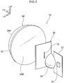
Fig. 2 is a perspective view showing schematic structure of the lighting device for a vehicle according to the first exemplary embodiment. -
Fig. 3 is a plan sectional diagram showing the schematic structure of the lighting device for a vehicle according to the first exemplary embodiment. -
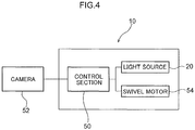
Fig. 4 is a block diagram showing schematic structure of the lighting device for a vehicle according to the first exemplary embodiment. -
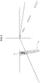
Fig. 5 is a descriptive diagram showing a region that is illuminated with light by the lighting device for a vehicle according to the first exemplary embodiment. -
Fig. 6A is a perspective view showing a lighting device for a vehicle according to a second exemplary embodiment. -
Fig. 6B is another perspective view showing the lighting device for a vehicle according to the second exemplary embodiment. -
Fig. 7 is a bottom sectional diagram showing schematic structure of the lighting device for a vehicle according to the second exemplary embodiment. -
Fig. 8 is a sectional diagram showing an aperture portion of a shading member of the lighting device for a vehicle according to the second exemplary embodiment. -
Fig. 9 is a sectional diagram showing a partial magnification of a mold that molds a holder of the lighting device for a vehicle according to the second exemplary embodiment. -
Fig. 10 is a descriptive diagram showing light that is illuminated by the lighting device for a vehicle according to the second embodiment. -
Fig. 11 is a descriptive diagram showing light that is illuminated by a lighting device for a vehicle according to a third exemplary embodiment. -
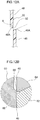
Fig. 12A is a sectional diagram showing an aperture portion of a shading member according to a comparative example. -
Fig. 12B is a sectional diagram showing a partial magnification of a mold that molds a holder according to the comparative example. - Herebelow, exemplary embodiments relating to the present disclosure are described in detail in accordance with the drawings. For convenience of description, the arrow UP that is shown where appropriate in the drawings indicates a vehicle upper direction, the arrow FR indicates a vehicle front direction, and the arrow LH indicates a vehicle left direction. Thus, in the following descriptions, where the directions up and down, front and rear, and left and right are recited without being particularly specified, the same represent up and down in the vehicle vertical direction, front and rear in the vehicle front-and-rear direction, and left and right in the vehicle left-and-right direction (the vehicle width direction).
- As shown in
Fig. 1 , avehicle 12 is equipped with a pair ofheadlamp units 14 at left and right, for assuring a field of view at the front side of thevehicle 12. That is, aheadlamp unit 14R is disposed at a right side front end portion of thevehicle 12, and aheadlamp unit 14L is disposed at a left side front end portion of thevehicle 12. - Each of the
headlamp unit 14R and theheadlamp unit 14L includes alow beam unit 16 that structures a vehicle width direction outer side portion thereof and ahigh beam unit 18 that structures a vehicle width direction inner side portion. Theheadlamp unit 14R andheadlamp unit 14L are formed with left-right symmetry in the vehicle width direction. - The
low beam unit 16 is structured so as to illuminate light (visible light) onto a low beam light distribution area of a road surface to the front side of thevehicle 12. Thehigh beam unit 18 illuminates light (visible light) at a high beam light distribution area, which is diagonally to the upper-front side relative to the low beam light distribution area illuminated by thelow beam unit 16. A lighting device for avehicle 10 according to the present exemplary embodiments is provided at the vehicle width direction outer side of thelow beam unit 16. - First, the lighting device for a
vehicle 10 according to a first exemplary embodiment is described. As shown inFig. 2 andFig. 3 , the lighting device for avehicle 10 is equipped with alight source 20 and a reflectingmember 24. Thelight source 20 illuminates light (visible light). The reflectingmember 24 includes a reflectingsurface 26 with a concave surface shape that reflects the light illuminated from thelight source 20 and causes the light to converge. - The lighting device for a
vehicle 10 is also equipped with a shadingmember 30 and a projectinglens 34. The shadingmember 30 includes anaperture portion 32, at which the light reflected and converged by the reflectingsurface 26 is incident. The projectinglens 34 emits light that has passed through theaperture portion 32 of theshading member 30 and is incident on the projectinglens 34 toward a target (for example, a pedestrian walking at a - roadside, a bicycle running at a roadside or the like that is at risk of collision with the
vehicle 12, which target is below referred to as "the pedestrian P"; seeFig. 5 ). - The
light source 20 is a high-brightness light source such as a light-emitting diode (LED), a semiconductor laser (a laser diode (LD)) or the like. Thelight source 20 is provided on acircuit board 22 that is electronically connected with a control section 50 (seeFig. 4 ). The reflectingmember 24 is integrally provided on thecircuit board 22 at a rear portion thereof, at a predetermined inclination angle with respect to the circuit board 22 (inFig. 2 , the reflectingmember 24 is depicted as being separated from the circuit board 22). - As shown in
Fig. 3 , the reflectingmember 24 is formed in a curved surface shape that bulges toward the rear side. A reflectingmirror 25 with a mirror finish is provided at an inner face (front face) of the reflectingmember 24. A surface (front face) of the reflectingmirror 25 serves as the reflectingsurface 26. Thus, the reflectingmember 24 of the present exemplary embodiment serves as a concave reflecting mirror (a reflector). The reflectingmember 24 apart from the reflectingmirror 25 is fabricated of resin. Light V that is illuminated from thelight source 20 is both reflected by the reflectingsurface 26 and converged toward theaperture portion 32 of theshading member 30 by the reflectingsurface 26. - In plan view and side view, a
front face 34A of the projectinglens 34 is formed in a curved surface shape that bulges toward the front side, and arear face 34B of the projectinglens 34 is formed in a planar surface shape. A protrudingportion 35 that protrudes to the diametric direction outer side in a concentric circular shape is integrally formed (in the circumferential direction) along the whole circumference of the projectinglens 34 at a rear side periphery edge portion of the projectinglens 34. The protrudingportion 35 is joined by laser welding to a front end portion (below referred to as a seat face) 28A of aholder 28. Theholder 28 is formed in a substantially circular tube shape with an optical axis direction in the front-and-rear direction. - That is, the protruding
portion 35 is adhered (welded) to theseat face 28A of theholder 28 by the protrudingportion 35 being abutted against theseat face 28A of theholder 28, a laser beam (not shown in the drawings) illuminated from the front side passing through the protrudingportion 35, and the laser beam fusing theseat face 28A of theholder 28. Hence, a front portion aperture of theholder 28 is closed off by the projectinglens 34. Note that therear face 34B of the projectinglens 34 may be formed in a curved surface shape bulging toward the rear side. - The projecting
lens 34 is configured such that light V that passes through theaperture portion 32 of theshading member 30 and is incident on therear face 34B is made parallel by being transmitted from therear face 34B to thefront face 34A of the projectinglens 34, and is emitted from thefront face 34A. Thus, light (visible light) V that is parallel light is emitted to the front side of thevehicle 12. - The shading
member 30 is attached to a rear end portion of theholder 28. The shadingmember 30 is formed in a rectangular flat plate shape, the lengths of the diagonals of which are less than an internal diameter of theholder 28. Anaperture 28B with a rectangular shape similar to that of theshading member 30 is formed at a rear end portion of theholder 28. That is, the rectangular-shapedaperture 28B of theholder 28 is closed off by the shadingmember 30. - The
aperture portion 32 is formed in a slit shape whose length direction is in the vertical direction at a substantially central portion of theshading member 30. The light (visible light) V that has been reflected and converged by the reflectingsurface 26 of the reflectingmember 24 passes through theaperture portion 32, and the light (visible light) V that has passed through theaperture portion 32 is incident on therear face 34B of the projectinglens 34. - As shown in
Fig. 4 , the lighting device for avehicle 10 includes a camera (including an image sensor) 52 and aswivel motor 54 that serves as an actuator. Thecamera 52 serves as a recognition unit that recognizes the pedestrian P as a target. On the basis of results of recognition by thecamera 52, theswivel motor 54 controls an orientation of the projectinglens 34 such that the light (visible light) V emitted from the projectinglens 34 is illuminated at the pedestrian P. - The
swivel motor 54 is provided at the lower side of theholder 28 and turns theholder 28, and thus the projectinglens 34, in a left-and-right direction about a rotation axis in the vertical direction. Thelight source 20,swivel motor 54 andcamera 52 of the lighting device for avehicle 10 are each electronically connected with thecontrol section 50. - Thus, on the basis of results of detection (recognition) by the
camera 52, the lighting device for avehicle 10 may illuminate the light (visible light) V toward at least the legs of the pedestrian P who is (walking at the roadside) at risk of collision with thevehicle 12, by thecontrol section 50 causing thelight source 20 of the lighting device for avehicle 10 to light up and driving the swivel motor 54 (turning the holder 28). - The following operations are described for the lighting device for a
vehicle 10 according to the present exemplary embodiment with the structure described above. - During night-time running of the vehicle 12 (including situations in which the
vehicle 12 is temporarily stopped at a traffic signal, a level crossing or the like), in a state in which at least the light source of the low beam unit 16 (not shown in the drawings) is lit up (a state in which light is illuminated at the low beam light distribution area at the front side of the vehicle 12), pedestrians P walking at the roadside are continuously imaged (detected) by thecamera 52. - When a pedestrian P walking at, for example, a roadside at the left side of the progress direction of the
vehicle 12, who is at risk of collision with thevehicle 12, is detected (recognized) by thecamera 52, thecontrol section 50 causes thelight source 20 of the lighting device for avehicle 10 to light up, controls theswivel motor 54, and turns theholder 28, and thus the projectinglens 34, in the leftward direction. As a result, as shown inFig. 5 , the light (visible light) V passing through the projectinglens 34 from the rear to the front is illuminated at the pedestrian P. - The light (visible light) V illuminated from the
light source 20 is reflected and converged by the reflectingsurface 26 of the reflectingmember 24 and made incident on theaperture portion 32 of theshading member 30. Therefore, the light illuminated from thelight source 20 may be made incident on theaperture portion 32 more efficiently than in a configuration in which light reflected by the reflectingsurface 26 is not converged toward theaperture portion 32. In other words, a usage efficiency of the light that is illuminated from thelight source 20 and made incident on theaperture portion 32 may be improved. - Because the
swivel motor 54 is driven and turns the projectinglens 34 on the basis of results of detection (recognition) by thecamera 52 and the light V is illuminated toward a pedestrian P who is at risk of collision with thevehicle 12, the light V may be illuminated at the pedestrian P efficiently (seeFig. 5 ). As a result, it is easier for a driver of thevehicle 12 to discern the pedestrian P who is at risk of collision with thevehicle 12. - Now, the lighting device for a
vehicle 10 according to a second exemplary embodiment is described. Portions that are the same as in the above-described first exemplary embodiment are assigned the same reference numerals and, as appropriate, are not described in detail. - As shown in
Fig. 6A, Fig. 6B andFig. 7 , in the lighting device for avehicle 10 according to the second exemplary embodiment, the shadingmember 30 and the reflectingmember 24 are both formed integrally with a holder in a substantially tubular shape that has the optical axis direction in the front-and-rear direction. Amold 60 in which theholder 28 is injection-molded is shown inFig. 9 . As shown inFig. 9 , themold 60 is structured by a fixeddie 62, amovable die 64 and aslide 66. - As shown in
Fig. 7 , the projectinglens 34 is constituted by a plural number (two in this exemplary embodiment) of focusinglenses lens 36 at the front side has a greater diameter than the focusinglens 38 at the rear side. In plan view and side view, afront face 36A of the focusinglens 36 is formed in a curved surface shape that is convex to the front side, and arear face 36B of the focusinglens 36 is formed in a curved surface shape that is convex to the rear side. - A protruding
portion 37 that protrudes to the diametric direction outer side in a concentric circular shape is integrally formed (in the circumferential direction) along the whole circumference of the focusinglens 36 at a periphery edge portion of the focusinglens 36. The protrudingportion 37 is joined by laser welding to theseat face 28A of theholder 28. That is, the protrudingportion 37 is adhered to theseat face 28A of theholder 28 by the protrudingportion 37 being abutted against theseat face 28A of theholder 28, a laser beam (not shown in the drawings) illuminated from the front side passing through the protrudingportion 37, and the laser beam fusing theseat face 28A of theholder 28. - The focusing
lens 38 at the rear side has a smaller diameter than the focusinglens 36 at the front side. In plan view and side view, afront face 38A of the focusinglens 38 is formed in a curved surface shape that is concave to the rear side, and arear face 38B of the focusinglens 38 is formed in a curved surface shape that is concave to the front side. A protrudingportion 39 that protrudes to the diametric direction outer side in a concentric circular shape is integrally formed (in the circumferential direction) along the whole circumference of the focusinglens 38 at a periphery edge portion of the focusinglens 38. - A
step portion 29 is integrally formed (in the circumferential direction) along the whole circumference of theholder 28 at a front portion side of aninner periphery face 28C of theholder 28. Thestep portion 29 is formed such that a rear portion side of the inner periphery face 28C relative to a front portion side has a smaller internal diameter than the front portion side. The focusinglens 38 at the rear side is inserted into theholder 28 such that a rear face of the protrudingportion 39 formed at the periphery edge portion thereof abuts against a front face of thestep portion 29, and the protrudingportion 39 is joined to thestep portion 29 by laser welding. - A
periphery edge portion 39A at the front side of the focusinglens 38 relative to the protrudingportion 39 is formed in a tapered shape that narrows toward the front side. A space S is formed between theperiphery edge portion 39A and theinner periphery face 28C of theholder 28. A laser beam (not shown in the drawings) illuminated from the front side through this space S passes through the protrudingportion 39 and reaches thestep portion 29. By fusing thestep portion 29, the laser beam adheres the protrudingportion 39 to thestep portion 29. - A
periphery edge portion 39B at the rear side of the focusinglens 38 relative to the protrudingportion 39 is formed in a tapered shape that narrows toward the rear side. Thus, the focusinglens 38 is formed with a structure that is easy to insert into theholder 28. However, provided it is easy to insert the focusinglens 38 into theholder 28, a tapered shape that narrows toward the rear side need not be formed at theperiphery edge portion 39B at the rear side of the focusinglens 38 relative to the protrudingportion 39. - As is also shown in
Fig. 6A, Fig. 6B andFig. 7 , asupport portion 40 substantially in a flat plate shape extends to the rear side from one of length direction (vertical direction) peripheral edge portions that structure theaperture portion 32 of theshading member 30. In a side view seen in the vehicle width direction, the front side of thesupport portion 40 opens in a substantially rectangular shape, and anaperture portion 42 continues from this front side. Theaperture portion 42 is formed in a substantially semicircular shape at the rear side of thesupport portion 40. - The reflecting
member 24 protrudes integrally from a periphery edge portion of the region of theaperture portion 42 that opens in the substantially semicircular shape. A recessedportion 44 in a substantially rectangular shape (seeFig. 6B ) is formed in a face at the opposite side of thesupport portion 40 from a face thereof at which the reflectingmember 24 is provided. The recessedportion 44 is for attachment of thecircuit board 22 including thelight source 20 to thesupport portion 40. - As described above, the reflecting
mirror 25 with a mirror finish is provided at the inner face of the reflectingmember 24 according to the present exemplary embodiment. Thus, the reflectingmember 24 serves as a concave reflecting mirror (a reflector). Apart from the reflectingmirror 25, the reflectingmember 24 is formed integrally with theholder 28. - As shown in
Fig. 7 to Fig. 9 , the shadingmember 30 is formed integrally with theholder 28 such that a right side region of theshading member 30 in a bottom view (below referred to as a "rightsemicircular portion 46"), from which thesupport portion 40 protrudes, is disposed at the rear side relative to a left side region of the shading member 30 (below referred to as a "leftsemicircular portion 48"), from which thesupport portion 40 does not protrude. More specifically, the leftsemicircular portion 48 and rightsemicircular portion 46 are offset in the front-and-rear direction such that a rear face of the leftsemicircular portion 48 is coplanar with a front face of the rightsemicircular portion 46. - A light incidence direction downstream side of a peripheral edge portion at the side of the
aperture portion 32 of theshading member 30 that is structured by the leftsemicircular portion 48 is formed in an acute-angled shape in a bottom sectional view (a plan sectional view). That is, in the bottom sectional diagram shown inFig. 8 , anend face 48A of this peripheral edge portion is formed at an acute angle such that an inclination angle θ of the end face 48A relative to the vehicle width direction is less than 90°. - The following operations are described for the lighting device for a
vehicle 10 according to the second exemplary embodiment with the structure described above. Descriptions of operations that that are the same as operations according to the first exemplary embodiment are omitted as appropriate. - During night-time running of the vehicle 12 (including situations in which the
vehicle 12 is temporarily stopped at a traffic signal, a level crossing or the like), in a state in which at least the light source of the low beam unit 16 (not shown in the drawings) is lit up (a state in which light is illuminated at the low beam light distribution area at the front side of the vehicle 12), pedestrians P walking at the roadside are continuously imaged (detected) by thecamera 52. - When a pedestrian P walking at, for example, a roadside at the left side of the progress direction of the
vehicle 12, who is at risk of collision with thevehicle 12, is detected (recognized) by thecamera 52, thecontrol section 50 causes thelight source 20 of the lighting device for avehicle 10 to light up, controls theswivel motor 54, and turns theholder 28, and thus the projecting lens 34 (the focusinglenses 36 and 38), in the leftward direction. As a result, as shown inFig. 5 , the light (visible light) V passing through the projecting lens 34 (the focusinglenses 36 and 38) from the rear to the front is illuminated at the pedestrian P. - The light (visible light) V illuminated from the
light source 20 is reflected and converged by the reflectingsurface 26 of the reflectingmember 24 and made incident on theaperture portion 32 of theshading member 30. Therefore, the light illuminated from thelight source 20 may be made incident on theaperture portion 32 more efficiently than in a configuration in which light reflected by the reflectingsurface 26 is not converged toward theaperture portion 32. In other words, a usage efficiency of the light that is illuminated from thelight source 20 and made incident on theaperture portion 32 may be improved. - Because the
swivel motor 54 is driven and turns the projecting lens 34 (the focusinglenses 36 and 38) on the basis of results of recognition by thecamera 52, and the light V is illuminated toward a pedestrian P who is at risk of collision with thevehicle 12, the light V may be illuminated at the pedestrian P efficiently (seeFig. 5 ). - Furthermore, because the projecting
lens 34 is constituted by the focusinglenses lens 34 is structured by a single lens. Therefore, it is easier for a driver of thevehicle 12 to discern the pedestrian P who is at risk of collision with thevehicle 12. - As shown in
Fig. 12A , if theend face 48A of the peripheral edge portion at the side of theaperture portion 32 that is structured by the leftsemicircular portion 48 were formed at a right angle with respect to the vehicle width direction (θ=90°), then of the light that is incident on theaperture portion 32, light that is reflected from anend face 46A of the rightsemicircular portion 46 would strike theend face 48A of the leftsemicircular portion 48 and might be blocked or might be reflected in an unintended direction. Thus, with this structure, the usage efficiency of the light illuminated from thelight source 20 and made incident on theaperture portion 32 might be reduced (there might be losses of light). - In contrast, in the
shading member 30 according to the present exemplary embodiment as shown inFig. 8 , the inclination angle θ with respect to the vehicle width direction of theend face 48A of the peripheral edge portion at the side of theaperture portion 32 that is structured by the leftsemicircular portion 48 is an acute angle (θ<90°). Therefore, of the light that is made incident on theaperture portion 32, cases of light reflected from theend face 46A of the rightsemicircular portion 46 striking and being blocked by theend face 48A of the left semicircular portion 48 (light being lost) may be suppressed or prevented. As a result, the usage efficiency of the light illuminated from thelight source 20 and made incident on theaperture portion 32 may be further improved. - As shown in
Fig. 8 andFig. 9 , the leftsemicircular portion 48 and rightsemicircular portion 46 of theshading member 30 according to the present exemplary embodiment are offset in the front-and-rear direction such that the rear face of the leftsemicircular portion 48 is coplanar with the front face of the rightsemicircular portion 46. Therefore, in contrast to a configuration in which the shading member 30 (the holder 28) is molded by themold 60 such that the rear face of the leftsemicircular portion 48 is coplanar with the rear face of the rightsemicircular portion 46, there is no need to form a small protrusion shape (a protrusion portion 68) in themold 60 as shown inFig. 12B . As a result, durability of themold 60 may be improved. - Because the
shading member 30 and the reflectingmember 24 are formed integrally with theholder 28, compared to a configuration in which theshading member 30 and the reflectingmember 24 are respectively separate bodies and are attached to theholder 28, a number of components may be reduced, in addition to which mountability of the shading member 30 (the aperture portion 32) and the reflecting member 24 (the reflecting surface 26) to the holder 28 (the projecting lens 34) is better, and positional offsets therebetween may be suppressed. - The protruding
portion 39 of the focusinglens 38 at the rear side, which constitutes the projectinglens 34 together with the focusinglens 36 at the front side, is joined by laser welding to thestep portion 29 formed at theinner periphery face 28C of theholder 28 in a similar manner to the protrudingportion 37 of the focusinglens 36 at the front side. Therefore, positional accuracy of the focusinglens 38 at the rear side with respect to the focusinglens 36 at the front side may be improved. - Finally, the lighting device for a
vehicle 10 according to a third exemplary embodiment is described. Portions that are the same as in the above-described first exemplary embodiment and second exemplary embodiment are assigned the same reference numerals and, as appropriate, are not described in detail (including operations that are the same). - As shown in
Fig. 11 , the third exemplary embodiment differs from the second exemplary embodiment described above only in that the concave surface shape of the reflecting mirror 25 (the reflecting surface 26) provided at the reflectingmember 24 is a freeform curved surface. The meaning of the term "freeform curved surface" as used here is intended to exclude curved surfaces that may be represented by simple expressions, such as the surface of a sphere, and to include curved surfaces expressed by higher-order expressions applied in 3D graphics, which represent curved surfaces that cannot be expressed by simple expressions. - When the light illuminated from the
light source 20 is reflected by the reflectingsurface 26 that is formed as a freeform curved surface, the light V is incident on theaperture portion 32 as light that is parallel over the vertical direction, without a focusing point. Consequently, illuminated light Vp that is illustrated inFig. 11 is illuminated light that is more uniform in the vertical direction than the illuminated light Vp illustrated inFig. 10 . - That is, the lighting device for a
vehicle 10 according to the third exemplary embodiment may improve the usage efficiency of the light (visible light) V illuminated from thelight source 20 compared to the lighting device for avehicle 10 according to the second exemplary embodiment. To describe this specifically using a numerical example, if the usage efficiency of light in the second exemplary embodiment is found to be 15.91%, the usage efficiency of light in the third exemplary embodiment is found to be 22.35%. Thus, the usage efficiency of light in the third exemplary embodiment is improved by approximately 40% compared to the second exemplary embodiment. - Hereabove, the lighting device for a
vehicle 10 according to the present exemplary embodiments is described by reference to the drawings. However, the lighting device for avehicle 10 according to the present exemplary embodiments is not limited to the configurations shown in the drawings; suitable design modifications may be applied within a scope not departing from the gist of the present disclosure. For example, in the lighting device for avehicle 10 according to the present exemplary embodiments, thelow beam unit 16 and thehigh beam unit 18 may be unified. - In the second exemplary embodiment and the third exemplary embodiment, it is sufficient if the projecting
lens 34 is constituted by a plural number of focusing lenses; the mode shown in the drawings in which the projectinglens 34 is constituted by the two focusinglenses lens 36 and focusinglens 38 constituting the projectinglens 34 are not limited to the respective shapes shown in the drawings.
Claims (5)
- A lighting device (10) for a vehicle, comprising:a light source (20) that illuminates light;a reflecting surface that reflects light illuminated from the light source (20) and causes the light to converge;a shading member (30) including an aperture portion (32) at which the light reflected and caused to converge by the reflecting surface (26) is made incident; anda projecting lens (34) at which light that has passed through the aperture portion (32) of the shading member (30) is incident, the projecting lens (34) emitting the light toward a target.
- The lighting device (10) for a vehicle according to claim 1, wherein the projecting lens (34) comprises a plurality of focusing lenses (36, 38).
- The lighting device (10) for a vehicle according to claim 1 or claim 2, wherein a light incidence direction downstream side of a peripheral edge portion structuring the aperture portion (32) of the shading member (30) is formed in an acute-angled shape in cross section.
- The lighting device (10) for a vehicle according to any one of claims 1 to 3, wherein the shading member (30) is formed integrally with a holder (28) that retains the projecting lens (34).
- The lighting device (10) for a vehicle according to any one of claims 1 to 4, further comprising:a recognition unit (52) that recognizes the target; andan actuator (54) that, on the basis of results of recognition by the recognition unit (52), controls the projecting lens (34) such that the light emitted therefrom illuminates the target.
Applications Claiming Priority (1)
| Application Number | Priority Date | Filing Date | Title |
|---|---|---|---|
| JP2017169878A JP6885268B2 (en) | 2017-09-04 | 2017-09-04 | Vehicle lighting device |
Publications (1)
| Publication Number | Publication Date |
|---|---|
| EP3450831A1 true EP3450831A1 (en) | 2019-03-06 |
Family
ID=63449272
Family Applications (1)
| Application Number | Title | Priority Date | Filing Date |
|---|---|---|---|
| EP18191516.6A Withdrawn EP3450831A1 (en) | 2017-09-04 | 2018-08-29 | Lighting device for vehicle |
Country Status (4)
| Country | Link |
|---|---|
| US (1) | US10788184B2 (en) |
| EP (1) | EP3450831A1 (en) |
| JP (1) | JP6885268B2 (en) |
| CN (1) | CN109424915A (en) |
Families Citing this family (6)
| Publication number | Priority date | Publication date | Assignee | Title |
|---|---|---|---|---|
| DE102018008760B4 (en) * | 2018-11-08 | 2025-10-16 | Mercedes-Benz Group AG | Vehicle headlights with a light source |
| TWI720464B (en) * | 2019-04-22 | 2021-03-01 | 天勤光電股份有限公司 | Reflective lighting system |
| TWI714064B (en) * | 2019-04-22 | 2020-12-21 | 天勤光電股份有限公司 | Lighting system |
| CN112432130A (en) * | 2019-08-26 | 2021-03-02 | 株式会社小糸制作所 | Lamp unit |
| KR102730878B1 (en) * | 2020-03-05 | 2024-11-18 | 에스케이하이닉스 주식회사 | Camera Module Having an Image Sensor and a Three-Dimensional Sensor |
| KR20220043782A (en) * | 2020-09-29 | 2022-04-05 | 에스엘 주식회사 | Lamp for vehicle |
Citations (10)
| Publication number | Priority date | Publication date | Assignee | Title |
|---|---|---|---|---|
| DE19627936A1 (en) * | 1996-07-11 | 1998-01-15 | Bosch Gmbh Robert | Double headlamp for vehicle |
| US20070064438A1 (en) * | 2005-09-13 | 2007-03-22 | Hiroyuki Ishida | Lamp unit for a vehicle headlamp |
| US20070133220A1 (en) * | 2005-12-08 | 2007-06-14 | Koito Manufacturing Co., Ltd. | Vehicle lighting device |
| JP2007287610A (en) * | 2006-04-20 | 2007-11-01 | Koito Mfg Co Ltd | Vehicle headlamp lamp unit |
| US7341367B2 (en) * | 2005-07-27 | 2008-03-11 | Koito Manufacturing Co., Ltd. | Vehicle headlamp |
| JP2009220631A (en) | 2008-03-13 | 2009-10-01 | Koito Mfg Co Ltd | Head lamp device for vehicle |
| US20100073950A1 (en) * | 2008-09-24 | 2010-03-25 | Ichikoh Industries, Ltd. | Vehicle lighting device |
| EP2690348A2 (en) * | 2012-07-24 | 2014-01-29 | Stanley Electric Co., Ltd. | Projector type headlight |
| DE102014200368A1 (en) * | 2014-01-10 | 2015-07-16 | Automotive Lighting Reutlingen Gmbh | Partial remote light projection light module for a motor vehicle headlight |
| WO2016162611A1 (en) * | 2015-04-08 | 2016-10-13 | Peugeot Citroen Automobiles Sa | Illumination device for a sealed-beam headlight of a vehicle, having a light beam which ensures constant illumination of an obstacle regardless of the position thereof |
Family Cites Families (13)
| Publication number | Priority date | Publication date | Assignee | Title |
|---|---|---|---|---|
| JP2577077Y2 (en) * | 1992-07-27 | 1998-07-23 | 株式会社小糸製作所 | Projection type automotive headlamp |
| JPH07159897A (en) * | 1993-12-07 | 1995-06-23 | Nippondenso Co Ltd | Light source device |
| FR2830073B1 (en) * | 2001-09-27 | 2003-12-12 | Valeo Vision | ELLIPTICAL LIGHTING PROJECTOR FOR A MOTOR VEHICLE COMPRISING A SECONDARY OPTICAL SYSTEM |
| JP4995748B2 (en) * | 2008-01-29 | 2012-08-08 | 株式会社小糸製作所 | Vehicle headlamp device and control method for vehicle headlamp device |
| JP5535663B2 (en) * | 2010-01-14 | 2014-07-02 | 株式会社小糸製作所 | Vehicle headlamp |
| JP5467917B2 (en) * | 2010-04-23 | 2014-04-09 | 株式会社小糸製作所 | Lighting fixtures for vehicles |
| US10220770B2 (en) * | 2011-07-08 | 2019-03-05 | Sl Corporation | Guide lamp for vehicle |
| JP5977111B2 (en) * | 2012-07-31 | 2016-08-24 | 株式会社小糸製作所 | Vehicle headlamp |
| JP2015138735A (en) * | 2014-01-24 | 2015-07-30 | スタンレー電気株式会社 | Vehicle lighting |
| JP6307991B2 (en) * | 2014-04-02 | 2018-04-11 | 市光工業株式会社 | Vehicle lighting |
| EP3434966B1 (en) * | 2016-03-24 | 2023-02-22 | Koito Manufacturing Co., Ltd. | Vehicle lamp and vehicle provided with it |
| JP6812120B2 (en) * | 2016-03-25 | 2021-01-13 | 株式会社小糸製作所 | Vehicle lighting fixtures and vehicles equipped with the vehicle lighting fixtures |
| JP6804213B2 (en) * | 2016-04-15 | 2020-12-23 | 株式会社小糸製作所 | Vehicle lighting fixtures and vehicles equipped with the vehicle lighting fixtures |
-
2017
- 2017-09-04 JP JP2017169878A patent/JP6885268B2/en active Active
-
2018
- 2018-08-29 EP EP18191516.6A patent/EP3450831A1/en not_active Withdrawn
- 2018-08-29 US US16/115,783 patent/US10788184B2/en active Active
- 2018-08-31 CN CN201811011353.6A patent/CN109424915A/en active Pending
Patent Citations (10)
| Publication number | Priority date | Publication date | Assignee | Title |
|---|---|---|---|---|
| DE19627936A1 (en) * | 1996-07-11 | 1998-01-15 | Bosch Gmbh Robert | Double headlamp for vehicle |
| US7341367B2 (en) * | 2005-07-27 | 2008-03-11 | Koito Manufacturing Co., Ltd. | Vehicle headlamp |
| US20070064438A1 (en) * | 2005-09-13 | 2007-03-22 | Hiroyuki Ishida | Lamp unit for a vehicle headlamp |
| US20070133220A1 (en) * | 2005-12-08 | 2007-06-14 | Koito Manufacturing Co., Ltd. | Vehicle lighting device |
| JP2007287610A (en) * | 2006-04-20 | 2007-11-01 | Koito Mfg Co Ltd | Vehicle headlamp lamp unit |
| JP2009220631A (en) | 2008-03-13 | 2009-10-01 | Koito Mfg Co Ltd | Head lamp device for vehicle |
| US20100073950A1 (en) * | 2008-09-24 | 2010-03-25 | Ichikoh Industries, Ltd. | Vehicle lighting device |
| EP2690348A2 (en) * | 2012-07-24 | 2014-01-29 | Stanley Electric Co., Ltd. | Projector type headlight |
| DE102014200368A1 (en) * | 2014-01-10 | 2015-07-16 | Automotive Lighting Reutlingen Gmbh | Partial remote light projection light module for a motor vehicle headlight |
| WO2016162611A1 (en) * | 2015-04-08 | 2016-10-13 | Peugeot Citroen Automobiles Sa | Illumination device for a sealed-beam headlight of a vehicle, having a light beam which ensures constant illumination of an obstacle regardless of the position thereof |
Also Published As
| Publication number | Publication date |
|---|---|
| US10788184B2 (en) | 2020-09-29 |
| JP6885268B2 (en) | 2021-06-09 |
| JP2019046691A (en) | 2019-03-22 |
| CN109424915A (en) | 2019-03-05 |
| US20190072253A1 (en) | 2019-03-07 |
Similar Documents
| Publication | Publication Date | Title |
|---|---|---|
| US10788184B2 (en) | Lighting device for vehicle | |
| CN109539164B (en) | Vehicle lamp | |
| CN109404851B (en) | Vehicle lamps | |
| JP6549212B2 (en) | Lighting module for car | |
| CN104364579B (en) | Lamps apparatus for vehicle | |
| JP7256017B2 (en) | Optical module with primary optics equipped with two shaping layers | |
| EP3450830B1 (en) | Illumination device for vehicle | |
| US20150210207A1 (en) | Vehicle Fog Lamp | |
| CN114060765A (en) | Vehicle lamp | |
| CN114992577A (en) | Lamp for vehicle and vehicle comprising same | |
| US11021097B2 (en) | Image projection module of a vehicle and a thick lens therefor | |
| KR101425967B1 (en) | Head light to correct chromatic aberration | |
| JP7665783B2 (en) | Optical module for a lighting system of a motor vehicle | |
| US9303837B2 (en) | Vehicular lamp having a translucent member having a center region that servers as a lens-like direct light control portion | |
| JP7784851B2 (en) | Vehicle lamp and automobile including same | |
| CN107543119B (en) | Lighting module for vehicle | |
| CN214745458U (en) | Lamp for a motor vehicle and motor vehicle comprising a lamp for a motor vehicle | |
| WO2023176444A1 (en) | Vehicular lamp | |
| JP2024524279A (en) | Optical module for light-emitting automotive systems | |
| CN211526339U (en) | Outer rear-view mirror indicator, outer rear-view mirror and vehicle | |
| US9296331B2 (en) | Vehicle headlight | |
| US10823363B2 (en) | Vehicular lamp | |
| JP7514588B2 (en) | Display device | |
| CN121828636A (en) | Optical module, method for operating optical module and motor vehicle | |
| KR20180070018A (en) | Lamp for vehicle |
Legal Events
| Date | Code | Title | Description |
|---|---|---|---|
| PUAI | Public reference made under article 153(3) epc to a published international application that has entered the european phase |
Free format text: ORIGINAL CODE: 0009012 |
|
| STAA | Information on the status of an ep patent application or granted ep patent |
Free format text: STATUS: REQUEST FOR EXAMINATION WAS MADE |
|
| 17P | Request for examination filed |
Effective date: 20180829 |
|
| AK | Designated contracting states |
Kind code of ref document: A1 Designated state(s): AL AT BE BG CH CY CZ DE DK EE ES FI FR GB GR HR HU IE IS IT LI LT LU LV MC MK MT NL NO PL PT RO RS SE SI SK SM TR |
|
| AX | Request for extension of the european patent |
Extension state: BA ME |
|
| STAA | Information on the status of an ep patent application or granted ep patent |
Free format text: STATUS: EXAMINATION IS IN PROGRESS |
|
| 17Q | First examination report despatched |
Effective date: 20200519 |
|
| STAA | Information on the status of an ep patent application or granted ep patent |
Free format text: STATUS: THE APPLICATION HAS BEEN WITHDRAWN |
|
| 18W | Application withdrawn |
Effective date: 20200917 |