EP3450772A1 - Hybrid spring for a hydraulic cylinder - Google Patents
Hybrid spring for a hydraulic cylinder Download PDFInfo
- Publication number
- EP3450772A1 EP3450772A1 EP18191638.8A EP18191638A EP3450772A1 EP 3450772 A1 EP3450772 A1 EP 3450772A1 EP 18191638 A EP18191638 A EP 18191638A EP 3450772 A1 EP3450772 A1 EP 3450772A1
- Authority
- EP
- European Patent Office
- Prior art keywords
- spring
- piston
- housing
- force
- assembly
- Prior art date
- Legal status (The legal status is an assumption and is not a legal conclusion. Google has not performed a legal analysis and makes no representation as to the accuracy of the status listed.)
- Granted
Links
Images



Classifications
-
- F—MECHANICAL ENGINEERING; LIGHTING; HEATING; WEAPONS; BLASTING
- F15—FLUID-PRESSURE ACTUATORS; HYDRAULICS OR PNEUMATICS IN GENERAL
- F15B—SYSTEMS ACTING BY MEANS OF FLUIDS IN GENERAL; FLUID-PRESSURE ACTUATORS, e.g. SERVOMOTORS; DETAILS OF FLUID-PRESSURE SYSTEMS, NOT OTHERWISE PROVIDED FOR
- F15B15/00—Fluid-actuated devices for displacing a member from one position to another; Gearing associated therewith
- F15B15/08—Characterised by the construction of the motor unit
- F15B15/14—Characterised by the construction of the motor unit of the straight-cylinder type
- F15B15/1423—Component parts; Constructional details
- F15B15/1476—Special return means
-
- F—MECHANICAL ENGINEERING; LIGHTING; HEATING; WEAPONS; BLASTING
- F15—FLUID-PRESSURE ACTUATORS; HYDRAULICS OR PNEUMATICS IN GENERAL
- F15B—SYSTEMS ACTING BY MEANS OF FLUIDS IN GENERAL; FLUID-PRESSURE ACTUATORS, e.g. SERVOMOTORS; DETAILS OF FLUID-PRESSURE SYSTEMS, NOT OTHERWISE PROVIDED FOR
- F15B15/00—Fluid-actuated devices for displacing a member from one position to another; Gearing associated therewith
- F15B15/08—Characterised by the construction of the motor unit
- F15B15/14—Characterised by the construction of the motor unit of the straight-cylinder type
- F15B15/1423—Component parts; Constructional details
- F15B15/1447—Pistons; Piston to piston rod assemblies
-
- F—MECHANICAL ENGINEERING; LIGHTING; HEATING; WEAPONS; BLASTING
- F16—ENGINEERING ELEMENTS AND UNITS; GENERAL MEASURES FOR PRODUCING AND MAINTAINING EFFECTIVE FUNCTIONING OF MACHINES OR INSTALLATIONS; THERMAL INSULATION IN GENERAL
- F16F—SPRINGS; SHOCK-ABSORBERS; MEANS FOR DAMPING VIBRATION
- F16F3/00—Spring units consisting of several springs, e.g. for obtaining a desired spring characteristic
- F16F3/02—Spring units consisting of several springs, e.g. for obtaining a desired spring characteristic with springs made of steel or of other material having low internal friction
- F16F3/04—Spring units consisting of several springs, e.g. for obtaining a desired spring characteristic with springs made of steel or of other material having low internal friction composed only of wound springs
- F16F3/06—Spring units consisting of several springs, e.g. for obtaining a desired spring characteristic with springs made of steel or of other material having low internal friction composed only of wound springs of which some are placed around others in such a way that they damp each other by mutual friction
-
- F—MECHANICAL ENGINEERING; LIGHTING; HEATING; WEAPONS; BLASTING
- F15—FLUID-PRESSURE ACTUATORS; HYDRAULICS OR PNEUMATICS IN GENERAL
- F15B—SYSTEMS ACTING BY MEANS OF FLUIDS IN GENERAL; FLUID-PRESSURE ACTUATORS, e.g. SERVOMOTORS; DETAILS OF FLUID-PRESSURE SYSTEMS, NOT OTHERWISE PROVIDED FOR
- F15B15/00—Fluid-actuated devices for displacing a member from one position to another; Gearing associated therewith
- F15B15/20—Other details, e.g. assembly with regulating devices
- F15B15/22—Other details, e.g. assembly with regulating devices for accelerating or decelerating the stroke
- F15B15/226—Other details, e.g. assembly with regulating devices for accelerating or decelerating the stroke having elastic elements, e.g. springs, rubber pads
-
- F—MECHANICAL ENGINEERING; LIGHTING; HEATING; WEAPONS; BLASTING
- F16—ENGINEERING ELEMENTS AND UNITS; GENERAL MEASURES FOR PRODUCING AND MAINTAINING EFFECTIVE FUNCTIONING OF MACHINES OR INSTALLATIONS; THERMAL INSULATION IN GENERAL
- F16F—SPRINGS; SHOCK-ABSORBERS; MEANS FOR DAMPING VIBRATION
- F16F9/00—Springs, vibration-dampers, shock-absorbers, or similarly-constructed movement-dampers using a fluid or the equivalent as damping medium
- F16F9/32—Details
- F16F9/3207—Constructional features
- F16F9/3221—Constructional features of piston rods
-
- F—MECHANICAL ENGINEERING; LIGHTING; HEATING; WEAPONS; BLASTING
- F15—FLUID-PRESSURE ACTUATORS; HYDRAULICS OR PNEUMATICS IN GENERAL
- F15B—SYSTEMS ACTING BY MEANS OF FLUIDS IN GENERAL; FLUID-PRESSURE ACTUATORS, e.g. SERVOMOTORS; DETAILS OF FLUID-PRESSURE SYSTEMS, NOT OTHERWISE PROVIDED FOR
- F15B15/00—Fluid-actuated devices for displacing a member from one position to another; Gearing associated therewith
- F15B15/08—Characterised by the construction of the motor unit
- F15B15/14—Characterised by the construction of the motor unit of the straight-cylinder type
- F15B15/1423—Component parts; Constructional details
- F15B15/1457—Piston rods
-
- F—MECHANICAL ENGINEERING; LIGHTING; HEATING; WEAPONS; BLASTING
- F15—FLUID-PRESSURE ACTUATORS; HYDRAULICS OR PNEUMATICS IN GENERAL
- F15B—SYSTEMS ACTING BY MEANS OF FLUIDS IN GENERAL; FLUID-PRESSURE ACTUATORS, e.g. SERVOMOTORS; DETAILS OF FLUID-PRESSURE SYSTEMS, NOT OTHERWISE PROVIDED FOR
- F15B2211/00—Circuits for servomotor systems
- F15B2211/70—Output members, e.g. hydraulic motors or cylinders or control therefor
- F15B2211/705—Output members, e.g. hydraulic motors or cylinders or control therefor characterised by the type of output members or actuators
- F15B2211/7051—Linear output members
- F15B2211/7052—Single-acting output members
-
- F—MECHANICAL ENGINEERING; LIGHTING; HEATING; WEAPONS; BLASTING
- F16—ENGINEERING ELEMENTS AND UNITS; GENERAL MEASURES FOR PRODUCING AND MAINTAINING EFFECTIVE FUNCTIONING OF MACHINES OR INSTALLATIONS; THERMAL INSULATION IN GENERAL
- F16F—SPRINGS; SHOCK-ABSORBERS; MEANS FOR DAMPING VIBRATION
- F16F9/00—Springs, vibration-dampers, shock-absorbers, or similarly-constructed movement-dampers using a fluid or the equivalent as damping medium
- F16F9/32—Details
- F16F9/36—Special sealings, including sealings or guides for piston-rods
Definitions
- the present invention relates to a hydraulic cylinder assembly and, more specifically, to a spring arrangement for use in a single-action hydraulic cylinder assembly.
- a piston cylinder assembly may generally include a housing defining a housing cavity; a piston movably supported by the housing, fluid supplied to the housing cavity applying a fluid force to cause the piston to extend out of the housing; and a spring return assembly connected between the housing and the piston and operable to apply a spring force to cause the piston to retract into the housing.
- the spring return assembly may include a first spring member connected at one end to the housing and having an opposite end, the first spring member being operable to apply a first spring force, and a second spring member connected at one end to the piston and having an opposite end, the second spring member being operable to apply a second spring force, the opposite end of each of the first spring member and the second spring member cooperating to apply the first spring force and the second spring force in series.
- a spring return assembly for a piston cylinder assembly may be provided.
- the piston cylinder assembly may include a housing defining a housing cavity, and a piston movably supported by the housing, fluid supplied to the housing cavity applying a fluid force to cause the piston to extend out of the housing
- the spring return assembly may generally include a tension spring connectable at one end to the housing and having an opposite end, the tension spring being operable to apply a first spring force; and a compression spring connectable at one end to the piston and having an opposite end, the compression spring being operable to apply a second spring force, the opposite end of each of the tension spring and the compression spring cooperating to apply the first spring force and the second spring force in series to cause the piston to retract into the housing.
- a method of operating a piston cylinder assembly may be provided.
- the piston cylinder assembly may include a housing defining a housing cavity, a piston movably supported by the housing, and a spring return assembly including a tension spring connected at one end to the housing, the tension spring being operable to apply a first spring force, and a compression spring connected at one end to the piston, the compression spring being operable to apply a second spring force.
- the method may generally include supplying fluid to the housing cavity to apply a fluid force to the piston to extend the piston out of the housing; applying a spring return force to the piston, the spring return force including the first spring force and the second spring force in series; and, when the spring return force of the spring return assembly is greater than the fluid force, retracting the piston into the housing.
- the present disclosure relates to a spring return of a piston-cylinder assembly.
- the spring return applies a non-constant spring rate over a cycle in order to provide a greater spring force.
- FIGS. 1-5 illustrate a piston and cylinder assembly 10 including a spring return assembly 12, a cylinder or housing 14 and a piston or plunger 18.
- the plunger 18 is movable relative to the housing 14.
- the assembly 10 is a single-acting hydraulic cylinder in which hydraulic fluid moves the plunger 18 in only a first direction. Once the plunger 18 is extended, the spring return assembly 12 retracts the plunger 18 in a second direction opposite the first direction.
- the illustrated spring return assembly 12 generally applies a non-constant spring rate over a cycle in order to provide a relatively greater spring force.
- the housing 14 is cylindrical in shape.
- the housing 14 includes an upper end surface 22, a lower end surface 26, and a side wall 30 extending between the surfaces 22, 26.
- the upper surface 22 defines an opening 34 to a housing cavity 38.
- the housing cavity 38 extends substantially through the length of the housing 14 along a housing axis 40 parallel to the side wall 30.
- the housing cavity 38 is defined by an internal surface 42 of the side wall 30.
- a stop ring 46 is fixed in the opening 34 to the internal housing surface 42 and has an opening 48.
- a first or outer ring surface 50 is flush with the upper housing surface 22. In other embodiments (not shown), the outer ring surface 50 may be above or below the surface 22.
- a second or inner ring surface 51 is opposite the stop outer ring surface 50.
- the housing defines a fluid or pressure port 52 (e.g., through the side wall 30).
- the pressure port 52 is proximate the lower housing surface 26.
- the pressure port 52 provides fluid communication between a reservoir storing an incompressible, hydraulic fluid (not shown) and the housing cavity 38.
- the plunger 18 is also cylindrical and is movably housed in the cavity 38 to extend out of and retract into the housing 14.
- an outer diameter of the plunger 18 is approximately equal to the diameter of the opening 48 in the stop ring 46.
- the plunger 18 includes an upper plunger surface 54, a lower plunger surface 58 and a plunger side wall 62 extending between the surfaces 54, 58.
- the lower plunger surface 58 defines a plunger opening 66 into a plunger cavity 70.
- the illustrated plunger cavity 70 extends substantially the length of the plunger 18 along a plunger axis 74 parallel to the housing axis 40.
- the plunger 18 includes a flange 71 extending radially from the plunger side wall 62.
- a lower flange surface provides the lower plunger surface 58, and an upper flange surface 73 is opposite the lower plunger surface 58.
- a diameter of the flange 71 is approximately equal to an inner diameter of the housing cavity 38. This allows the plunger 18 to move within the housing cavity 38 but helps to prevent hydraulic fluid in the housing cavity 38 from moving past the flange 71.
- the diameter of the flange 71 is greater than the inner diameter of the stop ring 46 to limit movement of the plunger 18 from the housing 14.
- a support rod 78 is connected to the plunger 18 and extends along the plunger axis 74 at least partially through the plunger cavity 70.
- the support rod 78 is connected at one end to the plunger 18 by a first securing member 82 (e.g., a bolt, a screw, or any similar fastening member).
- a flange 86 is connected to the other end of the support rod 78 by a second securing member 90 (e.g., a bolt, a screw, or any similar fastening member).
- the support rod 78 and the flange 86 are thus fixed within the plunger cavity 70 relative to the plunger 18.
- a sliding member 94 is movably supported on the support rod 78.
- the sliding member 94 has an inner diameter approximately equal to the diameter of the support rod 78 so that the sliding member 94 is supported for movement along the support rod 78.
- the outer diameter of the support rod 78 is less that an inner diameter of the plunger cavity 70.
- the spring return assembly 12 is connected between the housing 14 and the piston 18 to apply a return force on the piston 18.
- the illustrated assembly 12 includes at least two biasing members: a tension member (e.g., a tension spring 102) and a compression member (e.g., one or more compression springs 106, 110).
- the illustrated springs 102, 106, 110 are connected in series between the housing 14 and the piston 18.
- the assembly 12 may include more or fewer than the illustrated number of springs 102, 106, 110. Also, the springs 102, 106, 110, etc. may be arranged in a different manner (not shown).
- the springs 102, 106, 110 are concentric and wrap around the support rod 78.
- the tension spring 102 is secured at one end to the housing 14 (e.g., to the housing internal surface 46 by an insert 114).
- the insert 114 is secured to the housing 14 by a third securing member 118 (e.g., a bolt, a screw, or any similar fastening member), and the tension spring 102 threads onto the outer surface of the insert 114.
- the tension spring 102 is secured to the sliding member 94 (e.g., threaded onto the outer surface of the sliding member 94).
- An outer diameter of the tension spring is approximately equal to the inner diameter of the plunger cavity 70.
- the compression member (the compression springs 106, 110) is positioned between the flange 86, at one end, and the sliding member 94, at the other, and within the tension spring 102.
- one compression spring 110 is positioned within the other compression spring 106.
- the inner diameter of the inner spring 110 is larger than the diameter of the support rod 78 to allow relative movement between the compression member and the support rod 78.
- the outer diameter of the outer spring 106 (and of the other diameter of the flange 86) is smaller than the inner diameter of the tension spring 102 to allow relative movement between the springs 102, 106 (and between the spring 102 and the flange 86).
- the first compression spring 106 and the second compression spring 110 have a first spring constant and a second spring constant, respectively, and are in parallel with each other. This means that the first compression spring 106 and the second compression spring 110 deflect the same amount when a force is applied to the spring return assembly 12.
- the tension spring 102 has a third spring constant and is in series with the compressions spring 106, 110. This arrangement of springs 102, 106, 110 creates a hybrid spring.
- the first spring constant and the second spring constant can form an equivalent spring constant.
- the equivalent spring constant is greater than the third spring constant and can be used to represent an equivalent compression spring in series with the tension spring 102.
- the tension spring 102 experiences the same force as the equivalent compression spring when a force is applied to the spring return assembly 12.
- FIGS. 2-5 illustrate extension of the plunger 18 relative to the housing 14 during a stroke cycle.
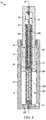
- FIG. 2 illustrates the assembly 10 in a retracted position, the initial and final positions of the stroke cycle.
- the upper plunger surface 54 is flush with the upper housing surface 22, and the lower plunger surface 58 is in contact with a lower cavity surface 122.
- the spring return assembly 12 e.g., the tension spring 102 and the compression spring(s) 106, 110) is in an initial position.
- hydraulic fluid is supplied through the pressure port 52 into the housing cavity 38 and provides a fluid force against the lower plunger surface 58.
- the plunger 18 begins to extend out of the housing cavity 38.
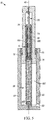
- FIG. 3 illustrates the assembly 10 in an initial extended position.
- the plunger 18 has begun to extend out of the housing cavity 38 so that the upper plunger surface 54 is no longer flush with the upper housing surface 22 and the lower plunger surface 58 moves out of contact with the lower housing surface 22.
- the tension spring 102 stretches along the plunger axis 74 to a length longer than a length of the housing 14.
- the tension spring 102 is the only spring that deflects. Because the spring constant of the tension spring 102 is less than the equivalent compression spring constant, the tension spring 102 deflects before the compression spring(s) 106, 110.
- the tension spring 102 may have a spring constant that is greater than the equivalent compression spring constant. In such a case, the tension spring 102 would not be the first spring to move.
- FIG. 4 illustrates the assembly 10 in a further extended position. In this position, the tension spring 102 continues to deflect along the plunger axis 74. Also, the fluid force is great enough that the compression spring(s) 106, 110 begin to be compressed. As the compression spring(s) 106, 110 begin to compress, the sliding member 94 moves along the support rod 78 towards the flange 86.
- the spring force in the spring return assembly 12 becomes non-linear.
- the slope of the F new line representing spring force over plunger stroke, is shallower from the initial extended position to the further extended position than from the retracted position to the initial extended position. This is because, as the compression spring(s) 106, 110 deflect, they reduce the amount deflection of the tension spring 102. However, the tension spring 102 still deflects at a greater rate than the compression spring(s) 106, 110.
- the plunger 18 extends further from the housing 14 to the fully extended position (see FIG. 5 ).
- the flange second surface 73 contacts the inner ring surface 51.
- the plunger 18 cannot extend further out of the housing cavity 38. In this position, the assembly 10 has completed one-half cycle, the extend portion of the cycle.
- the tension spring 102 deflects from the further extended position ( FIG. 4 ) to the fully extended position.
- the tension spring 102 deflected a length greater than the length of deflection of the compression spring(s) 106, 110.
- the compression spring(s) 106, 110 can also deflect between the further extended position and the fully extended position.
- the assembly 10 returns to the retracted position ( FIG. 2 ).
- the plunger 18 and the spring return assembly 12 will begin to return to the retracted positions (from FIG. 5 to FIG. 2 ).
- a component of the spring force supplied by the tension spring 102 will begin to retract the plunger 18 into the housing cavity 38.
- the flange first surface 72 will apply a force to the hydraulic fluid to force the hydraulic fluid out of the housing cavity 38 through the pressure port 52.
- the compression spring(s) 106, 110 begin to decompress, as the tension spring 102 continues to compress.
- the assembly 10 then moves to the initial extended position ( FIG. 3 ), and, in this position, the compression spring(s) 106, 110 have returned to their initial position.
- the tension spring 102 continues to compress and force hydraulic fluid from the housing cavity 38. Once all of the hydraulic fluid has left the housing cavity 38, the plunger 18 and the spring return assembly 12 have returned to the retracted position ( FIG. 2 ), and the stroke cycle is complete.
- FIG. 6 is a graph of the spring force over plunger stroke for an existing spring return assembly (F existing ) and for the illustrated assembly 10 including the spring return assembly 12 (F new ).
- F existing existing spring return assembly
- F new the force of the existing spring return assembly generally increases in a linear manner over the stroke length.
- the force of the spring return assembly 12 F new increases at a greater rate than that of F existing .
- the slope of the force of the spring return assembly 12 F new is shallower than that of F existing . From the further extended position 130 to the fully extended position 134, the slope of the force of the spring return assembly 12 F new returns to its original value, greater than that of F existing .
- the total force that the assembly 10 experiences and that the spring return assembly 12 applies is greater than the force in the existing design. This enables the plunger 18 to retract more quickly than the plunger in the existing design could.
Landscapes
- Engineering & Computer Science (AREA)
- General Engineering & Computer Science (AREA)
- Mechanical Engineering (AREA)
- Physics & Mathematics (AREA)
- Fluid Mechanics (AREA)
- Devices For Conveying Motion By Means Of Endless Flexible Members (AREA)
- Fluid-Damping Devices (AREA)
- Actuator (AREA)
Abstract
Description
- This application claims priority to
U.S. Provisional Patent Application No. 62/553,338, filed September 1, 2017 - The present invention relates to a hydraulic cylinder assembly and, more specifically, to a spring arrangement for use in a single-action hydraulic cylinder assembly.
- In one independent aspect, a piston cylinder assembly may generally include a housing defining a housing cavity; a piston movably supported by the housing, fluid supplied to the housing cavity applying a fluid force to cause the piston to extend out of the housing; and a spring return assembly connected between the housing and the piston and operable to apply a spring force to cause the piston to retract into the housing. The spring return assembly may include a first spring member connected at one end to the housing and having an opposite end, the first spring member being operable to apply a first spring force, and a second spring member connected at one end to the piston and having an opposite end, the second spring member being operable to apply a second spring force, the opposite end of each of the first spring member and the second spring member cooperating to apply the first spring force and the second spring force in series.
- In another independent aspect, a spring return assembly for a piston cylinder assembly may be provided. The piston cylinder assembly may include a housing defining a housing cavity, and a piston movably supported by the housing, fluid supplied to the housing cavity applying a fluid force to cause the piston to extend out of the housing The spring return assembly may generally include a tension spring connectable at one end to the housing and having an opposite end, the tension spring being operable to apply a first spring force; and a compression spring connectable at one end to the piston and having an opposite end, the compression spring being operable to apply a second spring force, the opposite end of each of the tension spring and the compression spring cooperating to apply the first spring force and the second spring force in series to cause the piston to retract into the housing.
- In yet another independent aspect, a method of operating a piston cylinder assembly may be provided. The piston cylinder assembly may include a housing defining a housing cavity, a piston movably supported by the housing, and a spring return assembly including a tension spring connected at one end to the housing, the tension spring being operable to apply a first spring force, and a compression spring connected at one end to the piston, the compression spring being operable to apply a second spring force. The method may generally include supplying fluid to the housing cavity to apply a fluid force to the piston to extend the piston out of the housing; applying a spring return force to the piston, the spring return force including the first spring force and the second spring force in series; and, when the spring return force of the spring return assembly is greater than the fluid force, retracting the piston into the housing.
- Other independent aspects of the invention may become apparent by consideration of the detailed description, claims and accompanying drawings.
-
-
FIG. 1 is a perspective view of a piston and cylinder assembly. -
FIG. 2 is a cross-sectional view of the assembly taken generally along line 2-2 inFIG. 1 , illustrating the assembly in a retracted position. -
FIG. 3 is another cross-sectional view of the assembly, illustrating the assembly in an initial extended position. -
FIG. 4 is another cross-sectional view of the assembly, illustrating the assembly in a further extended position. -
FIG. 5 is another cross-sectional view of the assembly, illustrating the assembly in a fully extended position. -
FIG. 6 is a graph comparing a spring force over a plunger stroke for an existing piston and cylinder assembly and the assembly ofFIG. 1 . - Before any independent embodiments of the invention are explained in detail, it is to be understood that the invention is not limited in its application to the details of construction and the arrangement of components set forth in the following description or illustrated in the following drawings. The invention is capable of other independent embodiments and of being practiced or of being carried out in various ways. Also, it is to be understood that the phraseology and terminology used herein is for the purpose of description and should not be regarded as limiting.
- Use of "including" and "comprising" and variations thereof as used herein is meant to encompass the items listed thereafter and equivalents thereof as well as additional items. Use of "consisting of' and variations thereof as used herein is meant to encompass only the items listed thereafter and equivalents thereof. Unless specified or limited otherwise, the terms "mounted," "connected," "supported," and "coupled" and variations thereof are used broadly and encompass both direct and indirect mountings, connections, supports, and couplings.
- In general, the present disclosure relates to a spring return of a piston-cylinder assembly. The spring return applies a non-constant spring rate over a cycle in order to provide a greater spring force.
-
FIGS. 1-5 illustrate a piston andcylinder assembly 10 including aspring return assembly 12, a cylinder orhousing 14 and a piston orplunger 18. Theplunger 18 is movable relative to thehousing 14. Theassembly 10 is a single-acting hydraulic cylinder in which hydraulic fluid moves theplunger 18 in only a first direction. Once theplunger 18 is extended, thespring return assembly 12 retracts theplunger 18 in a second direction opposite the first direction. The illustratedspring return assembly 12 generally applies a non-constant spring rate over a cycle in order to provide a relatively greater spring force. - In the illustrated embodiment, the
housing 14 is cylindrical in shape. Thehousing 14 includes anupper end surface 22, alower end surface 26, and aside wall 30 extending between thesurfaces upper surface 22 defines anopening 34 to ahousing cavity 38. Thehousing cavity 38 extends substantially through the length of thehousing 14 along ahousing axis 40 parallel to theside wall 30. - The
housing cavity 38 is defined by aninternal surface 42 of theside wall 30. Astop ring 46 is fixed in theopening 34 to theinternal housing surface 42 and has anopening 48. In the illustrated embodiment, a first orouter ring surface 50 is flush with theupper housing surface 22. In other embodiments (not shown), theouter ring surface 50 may be above or below thesurface 22. A second orinner ring surface 51 is opposite the stopouter ring surface 50. - The housing defines a fluid or pressure port 52 (e.g., through the side wall 30). The
pressure port 52 is proximate thelower housing surface 26. Thepressure port 52 provides fluid communication between a reservoir storing an incompressible, hydraulic fluid (not shown) and thehousing cavity 38. - In the illustrated embodiment, the
plunger 18 is also cylindrical and is movably housed in thecavity 38 to extend out of and retract into thehousing 14. In the illustrated embodiment, an outer diameter of theplunger 18 is approximately equal to the diameter of the opening 48 in thestop ring 46. Theplunger 18 includes anupper plunger surface 54, alower plunger surface 58 and aplunger side wall 62 extending between thesurfaces lower plunger surface 58 defines a plunger opening 66 into aplunger cavity 70. The illustratedplunger cavity 70 extends substantially the length of theplunger 18 along aplunger axis 74 parallel to thehousing axis 40. - The
plunger 18 includes aflange 71 extending radially from theplunger side wall 62. A lower flange surface provides thelower plunger surface 58, and anupper flange surface 73 is opposite thelower plunger surface 58. A diameter of theflange 71 is approximately equal to an inner diameter of thehousing cavity 38. This allows theplunger 18 to move within thehousing cavity 38 but helps to prevent hydraulic fluid in thehousing cavity 38 from moving past theflange 71. The diameter of theflange 71 is greater than the inner diameter of thestop ring 46 to limit movement of theplunger 18 from thehousing 14. - A
support rod 78 is connected to theplunger 18 and extends along theplunger axis 74 at least partially through theplunger cavity 70. Thesupport rod 78 is connected at one end to theplunger 18 by a first securing member 82 (e.g., a bolt, a screw, or any similar fastening member). Aflange 86 is connected to the other end of thesupport rod 78 by a second securing member 90 (e.g., a bolt, a screw, or any similar fastening member). Thesupport rod 78 and theflange 86 are thus fixed within theplunger cavity 70 relative to theplunger 18. - A sliding
member 94 is movably supported on thesupport rod 78. The slidingmember 94 has an inner diameter approximately equal to the diameter of thesupport rod 78 so that the slidingmember 94 is supported for movement along thesupport rod 78. The outer diameter of thesupport rod 78 is less that an inner diameter of theplunger cavity 70. - The
spring return assembly 12 is connected between thehousing 14 and thepiston 18 to apply a return force on thepiston 18. The illustratedassembly 12 includes at least two biasing members: a tension member (e.g., a tension spring 102) and a compression member (e.g., one ormore compression springs 106, 110). The illustrated springs 102, 106, 110 are connected in series between thehousing 14 and thepiston 18. - In other constructions (not shown), the
assembly 12 may include more or fewer than the illustrated number ofsprings springs - In the illustrated construction, the
springs support rod 78. Thetension spring 102 is secured at one end to the housing 14 (e.g., to the housinginternal surface 46 by an insert 114). The insert 114 is secured to thehousing 14 by a third securing member 118 (e.g., a bolt, a screw, or any similar fastening member), and thetension spring 102 threads onto the outer surface of the insert 114. At the other end, thetension spring 102 is secured to the sliding member 94 (e.g., threaded onto the outer surface of the sliding member 94). An outer diameter of the tension spring is approximately equal to the inner diameter of theplunger cavity 70. - The compression member (the compression springs 106, 110) is positioned between the
flange 86, at one end, and the slidingmember 94, at the other, and within thetension spring 102. In the illustrated construction, onecompression spring 110 is positioned within theother compression spring 106. The inner diameter of theinner spring 110 is larger than the diameter of thesupport rod 78 to allow relative movement between the compression member and thesupport rod 78. The outer diameter of the outer spring 106 (and of the other diameter of the flange 86) is smaller than the inner diameter of thetension spring 102 to allow relative movement between thesprings 102, 106 (and between thespring 102 and the flange 86). - The
first compression spring 106 and thesecond compression spring 110 have a first spring constant and a second spring constant, respectively, and are in parallel with each other. This means that thefirst compression spring 106 and thesecond compression spring 110 deflect the same amount when a force is applied to thespring return assembly 12. Thetension spring 102 has a third spring constant and is in series with thecompressions spring springs - The first spring constant and the second spring constant can form an equivalent spring constant. In the illustrated embodiment, the equivalent spring constant is greater than the third spring constant and can be used to represent an equivalent compression spring in series with the
tension spring 102. Thetension spring 102 experiences the same force as the equivalent compression spring when a force is applied to thespring return assembly 12. -
FIGS. 2-5 illustrate extension of theplunger 18 relative to thehousing 14 during a stroke cycle.FIG. 2 illustrates theassembly 10 in a retracted position, the initial and final positions of the stroke cycle. In the illustrated retracted position, theupper plunger surface 54 is flush with theupper housing surface 22, and thelower plunger surface 58 is in contact with alower cavity surface 122. The spring return assembly 12 (e.g., thetension spring 102 and the compression spring(s) 106, 110) is in an initial position. - To move from the retracted position toward the extended position, hydraulic fluid is supplied through the
pressure port 52 into thehousing cavity 38 and provides a fluid force against thelower plunger surface 58. When the fluid force exceeds the force of thespring return assembly 12, theplunger 18 begins to extend out of thehousing cavity 38. -
FIG. 3 illustrates theassembly 10 in an initial extended position. In this position, theplunger 18 has begun to extend out of thehousing cavity 38 so that theupper plunger surface 54 is no longer flush with theupper housing surface 22 and thelower plunger surface 58 moves out of contact with thelower housing surface 22. - As the
plunger 18 moves to the initial extended position, thetension spring 102 stretches along theplunger axis 74 to a length longer than a length of thehousing 14. In the illustratedspring return assembly 12, thetension spring 102 is the only spring that deflects. Because the spring constant of thetension spring 102 is less than the equivalent compression spring constant, thetension spring 102 deflects before the compression spring(s) 106, 110. - In alternative embodiments (not shown), the
tension spring 102 may have a spring constant that is greater than the equivalent compression spring constant. In such a case, thetension spring 102 would not be the first spring to move. - As additional hydraulic fluid force is applied to the
plunger 18, theplunger 18 extends further from thehousing 14.FIG. 4 illustrates theassembly 10 in a further extended position. In this position, thetension spring 102 continues to deflect along theplunger axis 74. Also, the fluid force is great enough that the compression spring(s) 106, 110 begin to be compressed. As the compression spring(s) 106, 110 begin to compress, the slidingmember 94 moves along thesupport rod 78 towards theflange 86. - By utilizing a
tension spring 102 in series with compression spring(s) 106, 110 in the current configuration of a hybrid spring, the spring force in thespring return assembly 12 becomes non-linear. As shown inFIG. 6 , the slope of the Fnew line, representing spring force over plunger stroke, is shallower from the initial extended position to the further extended position than from the retracted position to the initial extended position. This is because, as the compression spring(s) 106, 110 deflect, they reduce the amount deflection of thetension spring 102. However, thetension spring 102 still deflects at a greater rate than the compression spring(s) 106, 110. - As additional hydraulic fluid force is applied to the
plunger 18, theplunger 18 extends further from thehousing 14 to the fully extended position (seeFIG. 5 ). In the fully extended position, the flangesecond surface 73 contacts theinner ring surface 51. Once the flangesecond surface 73 is in contact with theinner ring surface 51, theplunger 18 cannot extend further out of thehousing cavity 38. In this position, theassembly 10 has completed one-half cycle, the extend portion of the cycle. - From the further extended position (
FIG. 4 ) to the fully extended position, only thetension spring 102 deflects. Thetension spring 102 deflected a length greater than the length of deflection of the compression spring(s) 106, 110. In alternative embodiments (not shown), the compression spring(s) 106, 110 can also deflect between the further extended position and the fully extended position. - To complete the stroke cycle, the
assembly 10 returns to the retracted position (FIG. 2 ). Once the force of thespring return assembly 12 is greater than the hydraulic fluid force, theplunger 18 and thespring return assembly 12 will begin to return to the retracted positions (fromFIG. 5 to FIG. 2 ). Initially, a component of the spring force supplied by thetension spring 102 will begin to retract theplunger 18 into thehousing cavity 38. As this occurs, the flange first surface 72 will apply a force to the hydraulic fluid to force the hydraulic fluid out of thehousing cavity 38 through thepressure port 52. - Once the
assembly 10 reaches the further extended position (FIG. 4 ), the compression spring(s) 106, 110 begin to decompress, as thetension spring 102 continues to compress. Theassembly 10 then moves to the initial extended position (FIG. 3 ), and, in this position, the compression spring(s) 106, 110 have returned to their initial position. Thetension spring 102 continues to compress and force hydraulic fluid from thehousing cavity 38. Once all of the hydraulic fluid has left thehousing cavity 38, theplunger 18 and thespring return assembly 12 have returned to the retracted position (FIG. 2 ), and the stroke cycle is complete. -
FIG. 6 is a graph of the spring force over plunger stroke for an existing spring return assembly (Fexisting) and for the illustratedassembly 10 including the spring return assembly 12 (Fnew). Generally, the force of the existing spring return assembly generally increases in a linear manner over the stroke length. - In comparison, between the retracted position and the initial
extended position 126, the force of the spring return assembly 12 Fnew increases at a greater rate than that of Fexisting. Once the compression spring(s) 106, 110 begin to deflect between the initial extended position and the furtherextended position 130, the slope of the force of the spring return assembly 12 Fnew is shallower than that of Fexisting. From the furtherextended position 130 to the fullyextended position 134, the slope of the force of the spring return assembly 12 Fnew returns to its original value, greater than that of Fexisting. - In the illustrated configuration, the total force that the
assembly 10 experiences and that thespring return assembly 12 applies is greater than the force in the existing design. This enables theplunger 18 to retract more quickly than the plunger in the existing design could. - By using one or more compression springs 106, 110 in series with a
tension spring 102 in theassembly 10, less displacement of thesprings springs such springs springs - Although aspects of the invention have been described in detail with reference to certain preferred constructions, variations and modifications exist within the scope and spirit of one or more independent aspects of the invention as described.
- One or more independent features and/or independent advantages of the invention may be set forth in the following claims:
Claims (15)
- A piston cylinder assembly comprising:a housing defining a housing cavity;a piston movably supported by the housing, fluid supplied to the cavity applying a fluid force to cause the piston to extend out of the housing; anda spring return assembly connected between the housing and the piston and operable to apply a spring force to cause the piston to retract into the housing, the spring return assembly includinga first spring member connected at one end to the housing and having an opposite end, the first spring member being operable to apply a first spring force, anda second spring member connected at one end to the piston and having an opposite end, the second spring member being operable to apply a second spring force, the opposite end of each of the first spring member and the second spring member cooperating to apply the first spring force and the second spring force in series.
- The piston cylinder assembly of claim 1, further comprising one or more of the following features:a) wherein the first spring member includes a tension spring;b) wherein a spring constant of the second spring member is greater than a spring constant of the first spring member; orc) wherein the piston defines a piston cavity and includes a support assembly within the piston cavity, the support assembly including a support rod connected at one end to the piston and having an opposite end, a flange supported on the opposite end, and a sliding member movable along the support rod.
- The piston cylinder assembly of claim 2, wherein the second spring member includes a compression spring.
- The piston cylinder assembly of claim 3, wherein the second spring member includes a pair of compression springs arranged in parallel.
- The piston cylinder assembly of claim 4, wherein the compression springs have an equivalent spring constant greater than a spring constant of the tension spring.
- The piston cylinder assembly of claim 2, wherein the second spring member includes a compression spring.
- The piston cylinder assembly of claim 2, wherein the opposite end of the first spring member is connected to the sliding member, and wherein the second spring member is positioned between the flange and the sliding member.
- The piston cylinder assembly of claim 7, wherein the second spring member includes a compression spring.
- A spring return assembly for a piston cylinder assembly, the piston cylinder assembly including a housing defining a housing cavity, and a piston movably supported by the housing, fluid supplied to the housing cavity applying a fluid force to cause the piston to extend out of the housing, the spring return assembly comprising:a tension spring connectable at one end to the housing and having an opposite end, the tension spring being operable to apply a first spring force; anda compression spring connectable at one end to the piston and having an opposite end, the compression spring being operable to apply a second spring force, the opposite end of each of the tension spring and the compression spring cooperating to apply the first spring force and the second spring force in series to cause the piston to retract into the housing.
- The spring return assembly of claim 9, further comprising one or more of the following features:d) wherein the compression spring is a first compression spring, the spring return assembly further comprising a second compression spring arranged in parallel with the first compression spring;e) wherein the piston defines a piston cavity, and wherein the spring return assembly further comprises a support assembly positioned within the piston cavity, the support assembly including a support rod connected at one end to the piston and having an opposite end, a flange supported on the opposite end, and a sliding member movable along the support rod; orf) wherein the spring return assembly is operable to apply a non-constant spring rate over a cycle of the piston.
- The spring return assembly of claim 10, wherein the first compression spring and the second compression spring are concentric.
- The spring return assembly of claim 10, wherein an equivalent spring constant of the first compression spring and the second compression spring is greater than a spring constant of the tension spring.
- The spring return assembly of claim 10, wherein the opposite end of the tension spring is connected to the sliding member, and wherein the compression spring is positioned between the flange and the sliding member.
- A method of operating a piston cylinder assembly, the piston cylinder assembly including a housing defining a housing cavity, a piston movably supported by the housing, and a spring return assembly including a tension spring connected at one end to the housing, the tension spring being operable to apply a first spring force, and a compression spring connected at one end to the piston, the compression spring being operable to apply a second spring force, the method comprising:supplying fluid to the housing cavity to apply a fluid force to the piston to extend the piston out of the housing;applying a spring return force to the piston, the spring return force including the first spring force and the second spring force in series; andwhen the spring return force of the spring return assembly is greater than the fluid force, retracting the piston into the housing.
- The method of claim 14, further comprising one or more of the following steps:g) extending the piston to an initial extended position in which only the first spring force is applied to the piston; andextending the piston to a fully extended position in which the first spring force and the second spring force are applied to the piston; orh) wherein the piston defines a piston cavity and includes a support assembly within the piston cavity, the support assembly including a support rod connected at one end to the piston and having an opposite end, a flange supported on the opposite end, and a sliding member movable along the support rod, the compression spring connected between the flange and the sliding member, the method further comprising moving the sliding member toward the flange and applying the second spring force.
Applications Claiming Priority (1)
| Application Number | Priority Date | Filing Date | Title |
|---|---|---|---|
| US201762553338P | 2017-09-01 | 2017-09-01 |
Publications (3)
| Publication Number | Publication Date |
|---|---|
| EP3450772A1 true EP3450772A1 (en) | 2019-03-06 |
| EP3450772C0 EP3450772C0 (en) | 2024-02-14 |
| EP3450772B1 EP3450772B1 (en) | 2024-02-14 |
Family
ID=63449332
Family Applications (1)
| Application Number | Title | Priority Date | Filing Date |
|---|---|---|---|
| EP18191638.8A Active EP3450772B1 (en) | 2017-09-01 | 2018-08-30 | Hybrid spring for a hydraulic cylinder |
Country Status (5)
| Country | Link |
|---|---|
| US (1) | US10760598B2 (en) |
| EP (1) | EP3450772B1 (en) |
| CN (1) | CN109424681B (en) |
| AU (1) | AU2018222981B2 (en) |
| ES (1) | ES2971650T3 (en) |
Families Citing this family (2)
| Publication number | Priority date | Publication date | Assignee | Title |
|---|---|---|---|---|
| AU2021391542A1 (en) * | 2020-11-17 | 2023-07-06 | Enerpac Tool Group Corp. | Method, apparatus and system for lifting railroad structures |
| JP7649160B2 (en) * | 2021-02-18 | 2025-03-19 | ピー・エス・シー株式会社 | Fluid Pressure Actuator |
Citations (3)
| Publication number | Priority date | Publication date | Assignee | Title |
|---|---|---|---|---|
| US2975762A (en) * | 1960-02-23 | 1961-03-21 | Leland F Blatt | Single action-quick return-tool and die cylinder assembly |
| WO1987005660A1 (en) * | 1986-03-22 | 1987-09-24 | Robert Bosch Gmbh | Actuating cylinder |
| CN2246205Y (en) * | 1995-12-29 | 1997-01-29 | 上海华光液压超高压技术应用公司 | Long range self-resetting hydrautic oil cylinder |
Family Cites Families (42)
| Publication number | Priority date | Publication date | Assignee | Title |
|---|---|---|---|---|
| FR1012219A (en) | 1950-12-04 | 1952-07-17 | ||
| US3049359A (en) | 1960-05-09 | 1962-08-14 | Gen Motors Corp | Rear wheel suspension system for vehicles |
| GB1115957A (en) | 1965-09-27 | 1968-06-06 | Girling Ltd | Improvements in or relating to vehicle suspension assemblies |
| US3399879A (en) * | 1965-02-20 | 1968-09-03 | Tokyo Keiki Seizosho Co Ltd | Shock preventive means for nautical meters |
| US3603610A (en) | 1968-12-20 | 1971-09-07 | Clifford W Mezey | Vehicle suspension apparatus |
| GB1315846A (en) | 1970-05-28 | 1973-05-02 | Moore J R C | Resilient mounting arrangements |
| US3864922A (en) | 1974-03-22 | 1975-02-11 | Halliburton Co | Sealed cushioning unit |
| DE7623283U1 (en) | 1976-07-23 | 1977-01-13 | Stabilus Gmbh, 5400 Koblenz | GUIDE COLUMN FOR CONTINUOUSLY HEIGHT ADJUSTMENT OF CHAIR SEATS |
| DE2806541A1 (en) | 1978-02-16 | 1979-08-23 | Fichtel & Sachs Ag | SHOCK ABSORBER OR SHOCK ABSORBER WITH HYDRAULIC-MECHANICAL PUSH STOP |
| US4657230A (en) | 1980-04-21 | 1987-04-14 | American Standard Inc. | Overtravel spring assembly for slack adjuster |
| DE3174727D1 (en) | 1980-11-25 | 1986-07-03 | Bayerische Motoren Werke Ag | Suspension system for vehicles |
| US4406473A (en) | 1981-12-07 | 1983-09-27 | Sexton Enterprises, Inc. | Safety stabilizer for vehicle steering linkage |
| DK149007C (en) * | 1983-06-01 | 1986-07-07 | Hvidt Moebelarkitektfirma A S | SPRING SYSTEM WITH VARIABLE SPRING CHARACTERISTICS |
| ES8503803A1 (en) | 1983-06-29 | 1985-03-01 | Boge Gmbh | Adjustable hydraulic damper apparatus |
| US4564048A (en) | 1984-05-25 | 1986-01-14 | Tayco Developments, Inc. | Pressure accumulator with composite helical spring |
| DE3423242C1 (en) | 1984-06-23 | 1985-11-07 | Dorma-Baubeschlag Gmbh & Co Kg, 5828 Ennepetal | Automatic door closer |
| US4733436A (en) | 1985-06-17 | 1988-03-29 | Exemplar, Inc. | Door mechanism spring assembly |
| US4719683A (en) | 1985-12-30 | 1988-01-19 | Windwinder Corporation | Preloaded spring, method and apparatus for forming same |
| EP0300470A1 (en) | 1987-07-21 | 1989-01-25 | Autoliv-Kolb GmbH & Co. | Device for fastening a safety belt lock support to a recipient affixed to a vehicle |
| AU607789B2 (en) | 1987-08-01 | 1991-03-14 | Britax-Kolb Gmbh & Co. | Acceleration sensor for safety systems and/or seat belt systems in motor vehicles |
| NL8800945A (en) | 1988-04-12 | 1989-11-01 | Koni Bv | SHOCK ABSORBER. |
| US5020752A (en) | 1990-06-12 | 1991-06-04 | Westinghouse Electric Corporation | Adjustable pedestal for tables and the like |
| DE4039816C1 (en) | 1990-12-13 | 1992-04-09 | Mercedes-Benz Aktiengesellschaft, 7000 Stuttgart, De | Belt drive tensioning system - uses cylinder with springs and damping fluid |
| FR2677929A1 (en) | 1991-06-24 | 1992-12-24 | Bianchi Mauro Sa | SUSPENSION METHOD FOR VEHICLES USING TWO RAIDERS, RESPECTIVELY DESIGNED FOR A GOOD LEVEL OF COMFORT AND A BEAUTIFUL LEVEL OF BEHAVIOR. |
| US5211379A (en) | 1991-12-18 | 1993-05-18 | P. L. Porter Company | Continuously self-compensating hydraulic positioner |
| DE4208887C2 (en) | 1992-03-19 | 2002-06-13 | Stabilus Gmbh | spring means |
| IT1271059B (en) | 1993-11-19 | 1997-05-26 | Stabilus Gmbh | STOP DEVICE TO FIX TWO MOVABLE OBJECTS ONE RELATIVE TO THE OTHER |
| US5542509A (en) | 1994-03-11 | 1996-08-06 | Gabriel Ride Control Products, Inc. | Shock absorber having externally adjustable compression |
| DE4419870A1 (en) | 1994-06-07 | 1995-12-14 | Suspa Compart Ag | Friction dampers, in particular for washing machines with a spin cycle |
| DE4445145A1 (en) * | 1994-12-17 | 1996-06-20 | Wabco Gmbh | Cylinder unit |
| DE19731139C2 (en) | 1997-07-21 | 2000-06-15 | Mannesmann Sachs Ag | Piston-cylinder unit, which is installed between a body and a wheel guide part of a vehicle |
| US6279765B1 (en) | 1998-01-20 | 2001-08-28 | Asf-Keystone, Inc. | Railcar cushioning device with internal spring |
| US6237904B1 (en) | 1999-02-10 | 2001-05-29 | John D. Shepherd | Motion stabilizer |
| DE19953372A1 (en) | 1999-02-10 | 2000-08-17 | Sachs Race Eng Gmbh | Variable damper with adjustable damping force has damping valve housing closed off at one end by a cover which has a device for engagement with the external adjusting unit |
| US6126154A (en) | 1999-02-10 | 2000-10-03 | Shepherd; John D. | Centering system |
| DE10011767C1 (en) | 2000-03-10 | 2001-10-31 | Stabilus Gmbh | Piston-cylinder unit |
| CN2537953Y (en) * | 2002-04-09 | 2003-02-26 | 中国人民解放军总装备部军械技术研究所 | Hydraulic pull-out device for basic explosive tube of mortar shell |
| US7677539B2 (en) | 2006-02-23 | 2010-03-16 | Barnes Group Inc. | Force control strut |
| DE102007015888A1 (en) | 2007-04-02 | 2008-10-09 | Bayerische Motoren Werke Aktiengesellschaft | Spring arrangement with adjustable spring rate and strut |
| US20120286462A1 (en) | 2010-05-27 | 2012-11-15 | Pepka Charles F | Preloaded dual-spring assembly |
| US20110291338A1 (en) | 2010-05-27 | 2011-12-01 | Pepka Charles F | Preloaded dual-spring assembly |
| CN205806297U (en) * | 2016-07-01 | 2016-12-14 | 浙江豪亿弹簧有限公司 | A kind of new type of compression spring |
-
2018
- 2018-08-30 AU AU2018222981A patent/AU2018222981B2/en active Active
- 2018-08-30 US US16/117,573 patent/US10760598B2/en active Active
- 2018-08-30 ES ES18191638T patent/ES2971650T3/en active Active
- 2018-08-30 EP EP18191638.8A patent/EP3450772B1/en active Active
- 2018-09-03 CN CN201811018856.6A patent/CN109424681B/en active Active
Patent Citations (3)
| Publication number | Priority date | Publication date | Assignee | Title |
|---|---|---|---|---|
| US2975762A (en) * | 1960-02-23 | 1961-03-21 | Leland F Blatt | Single action-quick return-tool and die cylinder assembly |
| WO1987005660A1 (en) * | 1986-03-22 | 1987-09-24 | Robert Bosch Gmbh | Actuating cylinder |
| CN2246205Y (en) * | 1995-12-29 | 1997-01-29 | 上海华光液压超高压技术应用公司 | Long range self-resetting hydrautic oil cylinder |
Also Published As
| Publication number | Publication date |
|---|---|
| US10760598B2 (en) | 2020-09-01 |
| ES2971650T3 (en) | 2024-06-06 |
| AU2018222981B2 (en) | 2024-03-14 |
| EP3450772C0 (en) | 2024-02-14 |
| AU2018222981A1 (en) | 2019-03-21 |
| CN109424681B (en) | 2021-11-09 |
| US20190072117A1 (en) | 2019-03-07 |
| CN109424681A (en) | 2019-03-05 |
| EP3450772B1 (en) | 2024-02-14 |
Similar Documents
| Publication | Publication Date | Title |
|---|---|---|
| KR102062591B1 (en) | Gas spring and gas spring components | |
| US9151304B2 (en) | Multi-stage hydraulic cylinder assembly | |
| AT519184B1 (en) | Length adjustable connecting rod with stop surfaces | |
| EP3380694A1 (en) | Cylinder-piston unit with a compensating sealing element | |
| US9581216B2 (en) | Tensioning device and component having such a tensioning device | |
| KR20090028458A (en) | Gas spring with guide | |
| US10760598B2 (en) | Hybrid spring for a hydraulic cylinder | |
| KR101205274B1 (en) | Low impact gas spring | |
| EP2519743B1 (en) | Piston pump having an inlet valve | |
| US9435336B2 (en) | Sealing device for a piston | |
| CN116249845B (en) | Locking system | |
| CN110382882A (en) | Length adjustable link with stop surface | |
| EP2198442B1 (en) | Hydraulic spring-loaded drive | |
| WO2019029986A1 (en) | PRESSURE MEMORY STORAGE, IN PARTICULAR FOR STORING BRAKE FLUID IN A BRAKING CIRCUIT OF AN ELECTRONICALLY SLIP-CONTROLLED VEHICLE BRAKING SYSTEM | |
| CN214331057U (en) | High-pressure unloading structure of hydraulic cylinder | |
| JP2618768B2 (en) | Two-stage telescopic lock actuator | |
| WO2015069801A1 (en) | High output hydraulic cylinder and piston arrangement | |
| WO2012004072A1 (en) | Hydropneumatic piston accumulator | |
| DE102018107057A1 (en) | Connecting rod for a variable compression internal combustion engine | |
| EP2212554B1 (en) | Radial piston pump | |
| RU92701U1 (en) | HYDROCYLINDER WITH BRAKING EFFECT | |
| DE19907297A1 (en) | Operating device for sending cylinder of hydraulic clutch of vehicle, with elastic element yielding when compression cavity expands | |
| DE20213023U1 (en) | End of travel damping piston for hydraulic piston and cylinder unit engages wall of cylinder and sides of main piston, and has spring and stop mechanism | |
| CN114562494A (en) | Durable hydraulic equipment capable of preventing multidirectional bearing |
Legal Events
| Date | Code | Title | Description |
|---|---|---|---|
| PUAI | Public reference made under article 153(3) epc to a published international application that has entered the european phase |
Free format text: ORIGINAL CODE: 0009012 |
|
| STAA | Information on the status of an ep patent application or granted ep patent |
Free format text: STATUS: THE APPLICATION HAS BEEN PUBLISHED |
|
| AK | Designated contracting states |
Kind code of ref document: A1 Designated state(s): AL AT BE BG CH CY CZ DE DK EE ES FI FR GB GR HR HU IE IS IT LI LT LU LV MC MK MT NL NO PL PT RO RS SE SI SK SM TR |
|
| AX | Request for extension of the european patent |
Extension state: BA ME |
|
| STAA | Information on the status of an ep patent application or granted ep patent |
Free format text: STATUS: REQUEST FOR EXAMINATION WAS MADE |
|
| 17P | Request for examination filed |
Effective date: 20190827 |
|
| RBV | Designated contracting states (corrected) |
Designated state(s): AL AT BE BG CH CY CZ DE DK EE ES FI FR GB GR HR HU IE IS IT LI LT LU LV MC MK MT NL NO PL PT RO RS SE SI SK SM TR |
|
| RAP1 | Party data changed (applicant data changed or rights of an application transferred) |
Owner name: ENERPAC TOOL GROUP CORP. |
|
| STAA | Information on the status of an ep patent application or granted ep patent |
Free format text: STATUS: EXAMINATION IS IN PROGRESS |
|
| 17Q | First examination report despatched |
Effective date: 20220218 |
|
| GRAP | Despatch of communication of intention to grant a patent |
Free format text: ORIGINAL CODE: EPIDOSNIGR1 |
|
| STAA | Information on the status of an ep patent application or granted ep patent |
Free format text: STATUS: GRANT OF PATENT IS INTENDED |
|
| P01 | Opt-out of the competence of the unified patent court (upc) registered |
Effective date: 20230608 |
|
| RIC1 | Information provided on ipc code assigned before grant |
Ipc: F15B 15/14 20060101AFI20230623BHEP |
|
| INTG | Intention to grant announced |
Effective date: 20230712 |
|
| GRAJ | Information related to disapproval of communication of intention to grant by the applicant or resumption of examination proceedings by the epo deleted |
Free format text: ORIGINAL CODE: EPIDOSDIGR1 |
|
| STAA | Information on the status of an ep patent application or granted ep patent |
Free format text: STATUS: EXAMINATION IS IN PROGRESS |
|
| GRAP | Despatch of communication of intention to grant a patent |
Free format text: ORIGINAL CODE: EPIDOSNIGR1 |
|
| STAA | Information on the status of an ep patent application or granted ep patent |
Free format text: STATUS: GRANT OF PATENT IS INTENDED |
|
| GRAS | Grant fee paid |
Free format text: ORIGINAL CODE: EPIDOSNIGR3 |
|
| INTC | Intention to grant announced (deleted) | ||
| INTG | Intention to grant announced |
Effective date: 20231130 |
|
| RIN1 | Information on inventor provided before grant (corrected) |
Inventor name: STANFORD, FRANTZ |
|
| GRAA | (expected) grant |
Free format text: ORIGINAL CODE: 0009210 |
|
| STAA | Information on the status of an ep patent application or granted ep patent |
Free format text: STATUS: THE PATENT HAS BEEN GRANTED |
|
| AK | Designated contracting states |
Kind code of ref document: B1 Designated state(s): AL AT BE BG CH CY CZ DE DK EE ES FI FR GB GR HR HU IE IS IT LI LT LU LV MC MK MT NL NO PL PT RO RS SE SI SK SM TR |
|
| REG | Reference to a national code |
Ref country code: GB Ref legal event code: FG4D |
|
| REG | Reference to a national code |
Ref country code: CH Ref legal event code: EP |
|
| REG | Reference to a national code |
Ref country code: DE Ref legal event code: R096 Ref document number: 602018065144 Country of ref document: DE |
|
| REG | Reference to a national code |
Ref country code: IE Ref legal event code: FG4D |
|
| U01 | Request for unitary effect filed |
Effective date: 20240303 |
|
| U07 | Unitary effect registered |
Designated state(s): AT BE BG DE DK EE FI FR IT LT LU LV MT NL PT SE SI Effective date: 20240307 |
|
| P04 | Withdrawal of opt-out of the competence of the unified patent court (upc) registered |
Effective date: 20240412 |
|
| REG | Reference to a national code |
Ref country code: ES Ref legal event code: FG2A Ref document number: 2971650 Country of ref document: ES Kind code of ref document: T3 Effective date: 20240606 |
|
| PG25 | Lapsed in a contracting state [announced via postgrant information from national office to epo] |
Ref country code: IS Free format text: LAPSE BECAUSE OF FAILURE TO SUBMIT A TRANSLATION OF THE DESCRIPTION OR TO PAY THE FEE WITHIN THE PRESCRIBED TIME-LIMIT Effective date: 20240614 |
|
| PG25 | Lapsed in a contracting state [announced via postgrant information from national office to epo] |
Ref country code: GR Free format text: LAPSE BECAUSE OF FAILURE TO SUBMIT A TRANSLATION OF THE DESCRIPTION OR TO PAY THE FEE WITHIN THE PRESCRIBED TIME-LIMIT Effective date: 20240515 |
|
| PG25 | Lapsed in a contracting state [announced via postgrant information from national office to epo] |
Ref country code: RS Free format text: LAPSE BECAUSE OF FAILURE TO SUBMIT A TRANSLATION OF THE DESCRIPTION OR TO PAY THE FEE WITHIN THE PRESCRIBED TIME-LIMIT Effective date: 20240514 Ref country code: HR Free format text: LAPSE BECAUSE OF FAILURE TO SUBMIT A TRANSLATION OF THE DESCRIPTION OR TO PAY THE FEE WITHIN THE PRESCRIBED TIME-LIMIT Effective date: 20240214 |
|
| PG25 | Lapsed in a contracting state [announced via postgrant information from national office to epo] |
Ref country code: RS Free format text: LAPSE BECAUSE OF FAILURE TO SUBMIT A TRANSLATION OF THE DESCRIPTION OR TO PAY THE FEE WITHIN THE PRESCRIBED TIME-LIMIT Effective date: 20240514 Ref country code: NO Free format text: LAPSE BECAUSE OF FAILURE TO SUBMIT A TRANSLATION OF THE DESCRIPTION OR TO PAY THE FEE WITHIN THE PRESCRIBED TIME-LIMIT Effective date: 20240514 Ref country code: IS Free format text: LAPSE BECAUSE OF FAILURE TO SUBMIT A TRANSLATION OF THE DESCRIPTION OR TO PAY THE FEE WITHIN THE PRESCRIBED TIME-LIMIT Effective date: 20240614 Ref country code: HR Free format text: LAPSE BECAUSE OF FAILURE TO SUBMIT A TRANSLATION OF THE DESCRIPTION OR TO PAY THE FEE WITHIN THE PRESCRIBED TIME-LIMIT Effective date: 20240214 Ref country code: GR Free format text: LAPSE BECAUSE OF FAILURE TO SUBMIT A TRANSLATION OF THE DESCRIPTION OR TO PAY THE FEE WITHIN THE PRESCRIBED TIME-LIMIT Effective date: 20240515 |
|
| PG25 | Lapsed in a contracting state [announced via postgrant information from national office to epo] |
Ref country code: PL Free format text: LAPSE BECAUSE OF FAILURE TO SUBMIT A TRANSLATION OF THE DESCRIPTION OR TO PAY THE FEE WITHIN THE PRESCRIBED TIME-LIMIT Effective date: 20240214 |
|
| U20 | Renewal fee for the european patent with unitary effect paid |
Year of fee payment: 7 Effective date: 20240723 |
|
| PG25 | Lapsed in a contracting state [announced via postgrant information from national office to epo] |
Ref country code: PL Free format text: LAPSE BECAUSE OF FAILURE TO SUBMIT A TRANSLATION OF THE DESCRIPTION OR TO PAY THE FEE WITHIN THE PRESCRIBED TIME-LIMIT Effective date: 20240214 |
|
| PG25 | Lapsed in a contracting state [announced via postgrant information from national office to epo] |
Ref country code: SM Free format text: LAPSE BECAUSE OF FAILURE TO SUBMIT A TRANSLATION OF THE DESCRIPTION OR TO PAY THE FEE WITHIN THE PRESCRIBED TIME-LIMIT Effective date: 20240214 |
|
| PG25 | Lapsed in a contracting state [announced via postgrant information from national office to epo] |
Ref country code: CZ Free format text: LAPSE BECAUSE OF FAILURE TO SUBMIT A TRANSLATION OF THE DESCRIPTION OR TO PAY THE FEE WITHIN THE PRESCRIBED TIME-LIMIT Effective date: 20240214 |
|
| PG25 | Lapsed in a contracting state [announced via postgrant information from national office to epo] |
Ref country code: SK Free format text: LAPSE BECAUSE OF FAILURE TO SUBMIT A TRANSLATION OF THE DESCRIPTION OR TO PAY THE FEE WITHIN THE PRESCRIBED TIME-LIMIT Effective date: 20240214 |
|
| PG25 | Lapsed in a contracting state [announced via postgrant information from national office to epo] |
Ref country code: SM Free format text: LAPSE BECAUSE OF FAILURE TO SUBMIT A TRANSLATION OF THE DESCRIPTION OR TO PAY THE FEE WITHIN THE PRESCRIBED TIME-LIMIT Effective date: 20240214 Ref country code: SK Free format text: LAPSE BECAUSE OF FAILURE TO SUBMIT A TRANSLATION OF THE DESCRIPTION OR TO PAY THE FEE WITHIN THE PRESCRIBED TIME-LIMIT Effective date: 20240214 Ref country code: RO Free format text: LAPSE BECAUSE OF FAILURE TO SUBMIT A TRANSLATION OF THE DESCRIPTION OR TO PAY THE FEE WITHIN THE PRESCRIBED TIME-LIMIT Effective date: 20240214 Ref country code: CZ Free format text: LAPSE BECAUSE OF FAILURE TO SUBMIT A TRANSLATION OF THE DESCRIPTION OR TO PAY THE FEE WITHIN THE PRESCRIBED TIME-LIMIT Effective date: 20240214 |
|
| REG | Reference to a national code |
Ref country code: DE Ref legal event code: R097 Ref document number: 602018065144 Country of ref document: DE |
|
| PLBE | No opposition filed within time limit |
Free format text: ORIGINAL CODE: 0009261 |
|
| STAA | Information on the status of an ep patent application or granted ep patent |
Free format text: STATUS: NO OPPOSITION FILED WITHIN TIME LIMIT |
|
| 26N | No opposition filed |
Effective date: 20241115 |
|
| REG | Reference to a national code |
Ref country code: CH Ref legal event code: PL |
|
| PG25 | Lapsed in a contracting state [announced via postgrant information from national office to epo] |
Ref country code: MC Free format text: LAPSE BECAUSE OF FAILURE TO SUBMIT A TRANSLATION OF THE DESCRIPTION OR TO PAY THE FEE WITHIN THE PRESCRIBED TIME-LIMIT Effective date: 20240214 Ref country code: CH Free format text: LAPSE BECAUSE OF NON-PAYMENT OF DUE FEES Effective date: 20240831 |
|
| PG25 | Lapsed in a contracting state [announced via postgrant information from national office to epo] |
Ref country code: IE Free format text: LAPSE BECAUSE OF NON-PAYMENT OF DUE FEES Effective date: 20240830 |
|
| U20 | Renewal fee for the european patent with unitary effect paid |
Year of fee payment: 8 Effective date: 20250723 |
|
| PGFP | Annual fee paid to national office [announced via postgrant information from national office to epo] |
Ref country code: ES Payment date: 20250901 Year of fee payment: 8 |
|
| PGFP | Annual fee paid to national office [announced via postgrant information from national office to epo] |
Ref country code: GB Payment date: 20250725 Year of fee payment: 8 |
|
| PG25 | Lapsed in a contracting state [announced via postgrant information from national office to epo] |
Ref country code: CY Free format text: LAPSE BECAUSE OF FAILURE TO SUBMIT A TRANSLATION OF THE DESCRIPTION OR TO PAY THE FEE WITHIN THE PRESCRIBED TIME-LIMIT; INVALID AB INITIO Effective date: 20180830 |
|
| PG25 | Lapsed in a contracting state [announced via postgrant information from national office to epo] |
Ref country code: HU Free format text: LAPSE BECAUSE OF FAILURE TO SUBMIT A TRANSLATION OF THE DESCRIPTION OR TO PAY THE FEE WITHIN THE PRESCRIBED TIME-LIMIT; INVALID AB INITIO Effective date: 20180830 |