EP3450764A1 - Tangential fan and air conditioner - Google Patents
Tangential fan and air conditioner Download PDFInfo
- Publication number
- EP3450764A1 EP3450764A1 EP18187154.2A EP18187154A EP3450764A1 EP 3450764 A1 EP3450764 A1 EP 3450764A1 EP 18187154 A EP18187154 A EP 18187154A EP 3450764 A1 EP3450764 A1 EP 3450764A1
- Authority
- EP
- European Patent Office
- Prior art keywords
- impellers
- blades
- impeller
- tangential fan
- pitch
- Prior art date
- Legal status (The legal status is an assumption and is not a legal conclusion. Google has not performed a legal analysis and makes no representation as to the accuracy of the status listed.)
- Withdrawn
Links
Images






Classifications
-
- F—MECHANICAL ENGINEERING; LIGHTING; HEATING; WEAPONS; BLASTING
- F04—POSITIVE - DISPLACEMENT MACHINES FOR LIQUIDS; PUMPS FOR LIQUIDS OR ELASTIC FLUIDS
- F04D—NON-POSITIVE-DISPLACEMENT PUMPS
- F04D17/00—Radial-flow pumps, e.g. centrifugal pumps; Helico-centrifugal pumps
- F04D17/02—Radial-flow pumps, e.g. centrifugal pumps; Helico-centrifugal pumps having non-centrifugal stages, e.g. centripetal
- F04D17/04—Radial-flow pumps, e.g. centrifugal pumps; Helico-centrifugal pumps having non-centrifugal stages, e.g. centripetal of transverse-flow type
-
- F—MECHANICAL ENGINEERING; LIGHTING; HEATING; WEAPONS; BLASTING
- F04—POSITIVE - DISPLACEMENT MACHINES FOR LIQUIDS; PUMPS FOR LIQUIDS OR ELASTIC FLUIDS
- F04D—NON-POSITIVE-DISPLACEMENT PUMPS
- F04D29/00—Details, component parts, or accessories
- F04D29/26—Rotors specially for elastic fluids
- F04D29/28—Rotors specially for elastic fluids for centrifugal or helico-centrifugal pumps for radial-flow or helico-centrifugal pumps
- F04D29/281—Rotors specially for elastic fluids for centrifugal or helico-centrifugal pumps for radial-flow or helico-centrifugal pumps for fans or blowers
- F04D29/282—Rotors specially for elastic fluids for centrifugal or helico-centrifugal pumps for radial-flow or helico-centrifugal pumps for fans or blowers the leading edge of each vane being substantially parallel to the rotation axis
- F04D29/283—Rotors specially for elastic fluids for centrifugal or helico-centrifugal pumps for radial-flow or helico-centrifugal pumps for fans or blowers the leading edge of each vane being substantially parallel to the rotation axis rotors of the squirrel-cage type
-
- F—MECHANICAL ENGINEERING; LIGHTING; HEATING; WEAPONS; BLASTING
- F04—POSITIVE - DISPLACEMENT MACHINES FOR LIQUIDS; PUMPS FOR LIQUIDS OR ELASTIC FLUIDS
- F04D—NON-POSITIVE-DISPLACEMENT PUMPS
- F04D29/00—Details, component parts, or accessories
- F04D29/26—Rotors specially for elastic fluids
- F04D29/28—Rotors specially for elastic fluids for centrifugal or helico-centrifugal pumps for radial-flow or helico-centrifugal pumps
- F04D29/30—Vanes
-
- F—MECHANICAL ENGINEERING; LIGHTING; HEATING; WEAPONS; BLASTING
- F04—POSITIVE - DISPLACEMENT MACHINES FOR LIQUIDS; PUMPS FOR LIQUIDS OR ELASTIC FLUIDS
- F04D—NON-POSITIVE-DISPLACEMENT PUMPS
- F04D29/00—Details, component parts, or accessories
- F04D29/66—Combating cavitation, whirls, noise, vibration or the like; Balancing
- F04D29/661—Combating cavitation, whirls, noise, vibration or the like; Balancing especially adapted for elastic fluid pumps
- F04D29/666—Combating cavitation, whirls, noise, vibration or the like; Balancing especially adapted for elastic fluid pumps by means of rotor construction or layout, e.g. unequal distribution of blades or vanes
Definitions
- the present invention relates to a tangential fan and an air conditioner.
- f frequency
- i integer of order
- N number of rotations (rpm)
- Z number of blades
- Japanese Patent No. 2770677 discloses arranging circular arc vanes (blades) in a circumferential direction at random pitches and displacing impellers each by 1° to 4° in the circumferential direction.
- Japanese Patent No. 3460350 discloses arranging circular arc vanes in a circumferential direction at random pitches and making at least one phase difference in the impellers different from the other phase differences.
- Japanese Patent No. 3564462 discloses connecting impellers while alternately displacing the impellers.
- each of the above documents displaces the impellers within one interval of the blades. Accordingly, even when the blades are arranged in each impeller at random pitches, the blades at the respective same positions may be aligned with each other at certain time intervals. When the blades at the respective same positions are aligned with each other at certain time intervals, frequencies of sounds generated by the tangential fan are not completely different from each other in phase, making it difficult to effectively reducing noise.
- impellers For example, different impellers, namely impellers each having blades arranged at different random pitches may be prepared. However, this increases the number of components and thus increases management and manufacturing costs.
- the present invention has been made in view of the above circumstances and aims to provide a tangential fan that is composed of one kind of impeller and has reduced noise, and an air conditioner.
- the tangential fan according to a first aspect of the present invention is a tangential fan including plural impellers connected to each other in a rotational axis direction, each impeller including plural blades circularly arranged about the rotational axis to form a cylindrical outer shape of the impeller, the tangential fan blowing out a fluid led into an inside of the tangential fan by rotation of the impellers, wherein the blades are arranged in the impeller at random pitches, and a value derived by dividing 360° by a total number of the blades is defined as a virtual average pitch angle, each of the plural impellers includes the blades in the same arrangement, and adjacent impellers of the plural impellers are connected to each other at a circular connection displacement angle that is larger than the virtual average pitch angle.
- the blades are arranged in the impeller at random pitches
- the impeller includes the blades in the same arrangement
- adjacent impellers are connected to each other at the circular connection displacement angle that is larger than the virtual average pitch angle derived by dividing 360° by a total number of the blades.
- each impeller includes the blades in the same arrangement, the tangential fan may be composed of one kind of impeller, eliminating the need for increasing the number of components and increasing management and manufacturing costs.
- the circular connection displacement angle may be larger than a value twice the virtual average pitch angle.
- the air conditioner according to a second aspect of the present invention is an air conditioner including an indoor unit and an outdoor unit, wherein the air conditioner includes, inside the indoor unit, the tangential fan of the above aspect.
- the impellers are connected to each other at the circular connection displacement angle that is larger than the virtual average pitch angle, and this allows to vary the timings at which the respective blades pass the same point.
- FIGS. 1 to 9 one embodiment of the present invention will be explained using FIGS. 1 to 9 .
- the air conditioner 1 for performing air conditioning (cooling, heating and dehumidifying) of an indoor space and the like is an apparatus that mainly consists of an outdoor unit 10 and an indoor unit 20.
- the outdoor unit 10 and the indoor unit 20 are connected with a refrigerant pipe 50 to form a closed refrigerant circuit.
- the outdoor unit 10 and the indoor unit 20 are also connected with electric wires (not shown in the figure) for power supply and control.
- reference numeral 51 in the figure denotes a remote controller for controlling operations, by which various operating conditions of the air conditioner 1 are set.
- the outdoor unit 10 includes, inside a housing 11 of a substantially rectangular parallelepiped shape, a compressor 12 for compressing a refrigerant, an outdoor heat exchanger 13 for exchanging heat between the refrigerant and an outdoor air, and an outdoor fan 14 facilitating the heat exchange between the refrigerant and the outdoor air in the outdoor heat exchanger 13.
- a four-way valve, an electronic expansion valve, a control unit and the like are also installed inside the housing 11.
- the outdoor heat exchanger 13 By switching a circulation direction of the refrigerant with the four-way valve, the outdoor heat exchanger 13 functions as a condenser in a cooling operation and as an evaporator in a heating operation.
- the indoor unit 20 mainly consists of a suction grill (air inlet) 25 provided to the front cover 23 to take in preconditioned air (hereinafter referred to as "fresh air") from a room, an indoor heat exchanger 26 provided to cool or heat the fresh air taken in by the suction grill 25, an air outlet 27 provided to the front panel 24 to return air undergone the heat exchange in the indoor heat exchanger 26 (hereinafter referred to as "conditioned air") to the room, and a tangential fan 28 provided to take in the fresh air from the suction grill 25 and blow out the conditioned air from the air outlet 27 to the room.
- conditioned air preconditioned air
- tangential fan 28 provided to take in the fresh air from the suction grill 25 and blow out the conditioned air from the air outlet 27 to the room.
- the indoor heat exchanger 26 and the tangential fan 28 are supported by the base body 22 inside the housing 21.
- the reference numeral 29 in the figure denotes a filter that is provided to remove impurities such as dust and refuse contained in the fresh air led into the indoor heat exchanger 26 through the suction grill 25.
- the air outlet 27 is provided with a louver and a flap (not shown in the figure) to adjust a blowing direction of the conditioned air.
- the indoor heat exchanger 26 functions as an evaporator in a cooling operation, and as a condenser in a heating operation.
- the tangential fan 28 driven by a motor is rotatably supported by the base body 22, which constitutes the housing 21 of the indoor unit 20.
- the tangential fan 28 is arranged on an air passage formed in the base body 22 so as to connect the suction grill 25 and the air outlet 27.
- FIG. 2 is a front view of the tangential fan provided to the indoor unit of the present embodiment.
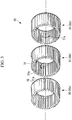
- FIG. 3 is a disassembled perspective view of a part of the tangential fan provided to the indoor unit of the present embodiment.
- the tangential fan 28 of the present embodiment includes plural impellers 30 connected to each other via intermediate plates 32 in a direction of a rotational axis CL.
- Each impeller 30 has a cylindrical shape formed by, for example, thirty-five (plural) blades (vanes) 31 circularly arranged about the rotational axis CL.
- the tangential fan 28 blows out a fluid led into the inside of the tangential fan 28 to the outside.
- each impeller 30 is arranged at random pitches, whereby each pitch, namely an interval between two adjacent blades 31 is unequal to each other.
- the impellers 30 are the same as each other; that is, the blades 31 of each impeller 30 are arranged at the same random pitches.
- FIG. 4 is a front view illustrating pitch intervals of a tangential fan without any displacement of impellers as a Reference Example.
- FIG. 4 shows arrangement and intervals of a part of the blades 31 of the four impellers 30 of impellers 30a, 30b, 30c and 30d. Each impeller 30 rotates, and the blades 31 move from the top to the bottom in the figure.
- the impellers 30 having a random pitch arrangement are not displaced from each other in a moving direction (circumferential direction) of the blades 31, and all of the blades 31 adjacent to each other via the intermediate plates 32 between the impellers 30 are arranged at the respective same positions.
- each impeller 30 is denoted by a reference numeral 30 with a trailing character of any one of a to d, and when the impellers 30 are not distinguished from each other, these trailing characters of a to d are omitted.
- FIG. 5 is a graph illustrating frequency characteristics of sounds of the tangential fan without any displacement of impellers as the Reference Example.
- the vertical axis indicates a sound pressure level (noise level at each frequency) Lp
- the horizontal axis indicates a frequency Hz of sounds.
- FIG. 6 is a front view illustrating pitch intervals of a tangential fan having impellers displaced within one pitch as a Reference Example.
- Each impeller 30 is connected to an adjacent impeller 30 while being displaced at a constant interval within the virtual average pitch angle of 10.3°.
- One pitch of the tangential fan 28 can be defined as an interval between two blades 31 represented by the virtual average pitch angle.
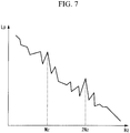
- FIG. 7 is a graph illustrating frequency characteristics of sounds of the tangential fan having impellers displaced within one pitch as the Reference Example.
- the vertical axis indicates a sound pressure level (noise level at each frequency) Lp
- the horizontal axis indicates a frequency Hz of sounds.
- the impellers 30 are displaced from each other by more than one pitch.
- FIG. 8 illustrates pitch intervals of the tangential fan according to one embodiment of the present invention (a representative figure illustrating displacement of one pitch + within one pitch).
- the adjacent impeller 30 is rotated by one pitch, and further displaced within one pitch as is conventional, and the impellers 30 are connected to each other in this state.
- this further displacement of the impeller 30 within one pitch as is conventional is made in order to avoid the situation where all of the blades 31 of any two impellers 30 are aligned at the respective same positions, which may occur with the displacement of one pitch alone.
- the displacement within one pitch is 10% to 50% of the virtual average pitch angle.
- the impeller 30 is connected to the adjacent impeller 30 while being displaced at the circular connection displacement angle ⁇ .
- the blades 31 of each impeller 30 at the respective same positions are displaced by more than one pitch since the impellers 30 are connected to each other at the circular connection displacement angle ⁇ , which is larger than the virtual average pitch angle. Accordingly, the blades 31 have random intervals between adjacent impellers 30 like the blades 31 of the impellers 30b, 30c and 30d indicated by the long and short dashed lines with respect to the blade 31 of the impeller 30a indicated by the bold line, and thus the blades 31 pass a reference point indicated by the broken line at different timings.
- the blade 31 of the adjacent impeller 30 may pass the reference point earlier, like the blade 31 of the impeller 30d indicated by the bold broken line.
- each blade 31 is arranged in a completely different manner in a circumferential direction by virtue of the random pitch arrangement, and thus all of the blades 31 are positioned at different positions when the impellers 30 are compared with each other at the same point like the above reference point.
- the blades 31 of the impellers 30 pass the same point at different timings, and this makes frequencies of generated sounds deviated from each other.
- FIG. 9 is a graph illustrating frequency characteristics of sounds of the tangential fan according to one embodiment of the present invention.
- the vertical axis indicates the sound pressure level (noise level at each frequency) Lp
- the horizontal axis indicates the frequency Hz of sounds.
- the circular connection displacement angle may be any other value as long as the value is larger than one pitch.
- an adjacent impeller 30 may be rotated by 30% in the circumferential direction, instead of one pitch.
- the adjacent impeller 30 is rotated by 30% in the circumferential direction, and further displaced within one pitch as is conventional, and the impellers 30 are connected to each other in this state.
- this further displacement of the impeller 30 within one pitch as is conventional is made in order to avoid the situation where all of the blades 31 of any two impellers 30 are aligned at the respective same positions, which may occur with the 30% rotation alone.
- the displacement within one pitch is 10% to 50% of the virtual average pitch angle.
- the circular connection displacement angle which is a displacement angle of each impeller 30, is expressed by the following formula (2) (30% rotation in the circumferential direction + displacement within one pitch): ⁇ 360 ° ⁇ 0.3 + 360 ° / 35 ⁇ 0.1 to 0.5
- FIG. 3 illustrates a schematic view of the impellers 30 connected to each other with each adjacent impeller 30 being rotated by 30% in the circumferential direction and further displaced within one pitch.
- each of the impellers 30a, 30b and 30c the blades 31 are arranged at random pitches, and each of the impellers 30a, 30b and 30c has the blades 31 in the same arrangement.
- the blades 31a arranged at the same positions in the respective impellers 30b and 30c can be selected.
- the blade 31a of the impeller 30a As shown in FIG. 3 , with the blade 31a of the impeller 30a as a reference, the blade 31a of the adjacent impeller 30b is rotated by 30% in the circumferential direction and further displaced to a position within one pitch. In this state, the impeller 30a and the impeller 30b are connected to each other. Likewise, with the blade 31a of the impeller 30b as a reference, the blade 31a of the adjacent impeller 30c is rotated by 30% in the circumferential direction and further displaced to a position within one pitch. In this state, the impeller 30b and the impeller 30c are connected to each other.
- the circular connection displacement angle is defined as two pitches or more.
- the adjacent impeller 30 is rotated or reversely rotated in the circumferential direction by n times the virtual average pitch angle (n is an integer of 2, 3, ... 34), and further displaced within one pitch as is conventional.
- the impellers 30 are connected to each other in this state.
- the displacement within one pitch is 10% to 50% of the virtual average pitch angle.
- the circular connection displacement angle which is a displacement angle of each impeller 30, is expressed by the following formula (3). ⁇ 360 ° / 35 ⁇ n + 360 ° / 35 ⁇ 0.1 to 0.5
- n is an integer of 2 to 34.
- an appropriate combination thereof can be set according the kind of the random pitch arrangement and a combination of units on which the impellers 30 are mounted.
- the circular connection displacement angle can be determined according to the frequency of sounds to be reduced among generated sounds, and this allows to connect the impellers 30 based on their characteristics such as the configuration of each impeller 30 and the kind of the random pitch arrangement.
- the manner of connecting the impellers 30, namely the manner of setting the circular connection displacement angle of each impeller 30 may be determined from tests to derive a value at which the noise can be most effectively reduced.
- the circular connection displacement angle is set according to the number of blades 31.
- the adjacent impeller 30 is rotated or reversely rotated in the circumferential direction by n times the virtual average pitch angle (n is an integer of 1, 2, ... z-1), and further displaced within one pitch as is conventional.
- the impellers 30 are connected to each other in this state.
- the displacement within one pitch is 10% to 50% of the virtual average pitch angle.
- the circular connection displacement angle which is a displacement angle of each impeller 30, is expressed by the following formula (4). ⁇ 360 ° / z ⁇ n + 360 ° / z ⁇ 0.1 to 0.5
- z is the number of blades 31 arranged in the impeller 30, "360°/z” is the virtual average pitch angle, "(360°/z) ⁇ (0.1 to 0.5)" is the displacement within one pitch. Also, n is an integer of 1 to (z - 1).
- the circular connection displacement angle can be determined according to the frequency of sounds to be reduced among generated sounds, and this allows to connect the impellers 30 based on their characteristics such as the configuration of each impeller 30 and the kind of the random pitch arrangement.
- the manner of connecting the impellers 30, namely the manner of setting the circular connection displacement angle of each impeller 30 may be determined from tests to derive a value at which the noise can be most effectively reduced.
- the tangential fan and the air conditioner according to the present embodiment produce the following functions and effects.
- the tangential fan 28 includes plural impellers 30 connected to each other in a rotational axis direction each including plural blades 31 circularly arranged about the rotational axis to form a cylindrical outer shape of each impeller 30, and the tangential fan 28 blows out a fluid led into an inside of the tangential fan 28 by rotation of the impellers 30.
- the blades 31 are arranged in each impeller 30 at random pitches
- each impeller 30 includes the blades 31 in the same arrangement
- the adjacent impellers 30 are connected to each other at the circular connection displacement angle that is larger than the virtual average pitch angle derived by dividing 360° by a total number of the blades 31. This complicates the arrangement of the blades 31 in the rotational axis direction, making almost all of the blades 31 positioned at respective different positions.
- the tangential fan 28 more effectively exerts the effects of the random pitch arrangement, namely irregularizing the periodicities of sound sources and dispersing Blade Pass Frequency noise to plural low peaks.
- the tangential fan 28 may be composed of one kind of impeller 30, eliminating the need for increasing the number of components and increasing management and manufacturing costs.
- the circular connection displacement angle is larger than the value twice the virtual average pitch angle, the arrangement of the blades 31 is made further nonperiodic and complicated, allowing to position almost all of the blades 31 at respective different positions.
- the tangential fan 28 is provided to the indoor unit 20 of the air conditioner 1 in the above embodiments, the tangential fan 28 may be provided to any other air operation apparatus such as a blower.
Landscapes
- Engineering & Computer Science (AREA)
- Mechanical Engineering (AREA)
- General Engineering & Computer Science (AREA)
- Structures Of Non-Positive Displacement Pumps (AREA)
- Air-Conditioning Room Units, And Self-Contained Units In General (AREA)
Abstract
A tangential fan that is composed of one kind of impeller and has a reduced noise, and an air conditioner are provided. The tangential fan 28 includes plural impellers 30 connected to each other in a rotational axis direction, each impeller 30 including plural blades 31 circularly arranged about the rotational axis to form a cylindrical outer shape of the impeller 30, the tangential fan 28 blowing out a fluid led into an inside of the tangential fan 28 by rotation of the impellers 30, wherein the blades 31 are arranged in each impeller 30 at random pitches, a value derived by dividing 360° by a total number of the blades 31 is defined as a virtual average pitch angle, each of the plural impellers 30 includes the blades 31 in the same arrangement, and adjacent impellers 30 of the plural impellers 30 are connected to each other at a circular connection displacement angle that is larger than the virtual average pitch angle.
Description
- The present invention relates to a tangential fan and an air conditioner.
- A tangential fan has been known as a fan used for apparatuses such as an indoor unit of an air conditioner. Unlike an axial fan and a centrifugal fan, the tangential fan is long in a width direction (rotational axis direction) and its shape is formed of plural impellers connected to each other. In each impeller, plural blades are arranged in a circumferential direction, and a peculiar sound such as Blade Pass Frequency noise (f=i × (N/60) × Z; f: frequency; i: integer of order; N: number of rotations (rpm); Z: number of blades) may be generated due to reasons such as an interference of each blade and the surroundings.
- Since the tangential fan is long in the width direction, sounds of the same frequencies generated by rotation may produce a peak noise unpleasant to a user, due to amplification, interference or resonance of the sounds.
- To reduce the noise, several countermeasures have been taken by changing a configuration of the tangential fan.
- For example, the Publication of Japanese Patent No.
2770677 - Also, the Publication of Japanese Patent No.
3460350 - Also, the Publication of Japanese Patent No.
3564462 - Also, the Publication of Japanese Patent No.
4831707 - However, the invention of each of the above documents displaces the impellers within one interval of the blades. Accordingly, even when the blades are arranged in each impeller at random pitches, the blades at the respective same positions may be aligned with each other at certain time intervals. When the blades at the respective same positions are aligned with each other at certain time intervals, frequencies of sounds generated by the tangential fan are not completely different from each other in phase, making it difficult to effectively reducing noise.
- To complicate the displacement of impellers, for example, different impellers, namely impellers each having blades arranged at different random pitches may be prepared. However, this increases the number of components and thus increases management and manufacturing costs.
- The present invention has been made in view of the above circumstances and aims to provide a tangential fan that is composed of one kind of impeller and has reduced noise, and an air conditioner.
- To solve the above problem, the tangential fan and the air conditioner of the present invention adopt the following solutions.
- The tangential fan according to a first aspect of the present invention is a tangential fan including plural impellers connected to each other in a rotational axis direction, each impeller including plural blades circularly arranged about the rotational axis to form a cylindrical outer shape of the impeller, the tangential fan blowing out a fluid led into an inside of the tangential fan by rotation of the impellers, wherein the blades are arranged in the impeller at random pitches, and a value derived by dividing 360° by a total number of the blades is defined as a virtual average pitch angle, each of the plural impellers includes the blades in the same arrangement, and adjacent impellers of the plural impellers are connected to each other at a circular connection displacement angle that is larger than the virtual average pitch angle.
- According to the present aspect, in the tangential fan including plural impellers connected to each other in a rotational axis direction each including plural blades circularly arranged about the rotational axis to form a cylindrical outer shape of the impeller, and blowing out a fluid led into an inside of the tangential fan by rotation of the impellers, the blades are arranged in the impeller at random pitches, the impeller includes the blades in the same arrangement, and adjacent impellers are connected to each other at the circular connection displacement angle that is larger than the virtual average pitch angle derived by dividing 360° by a total number of the blades. This complicates the arrangement of the blades in the rotational axis direction and positions almost all of the blades at respective different positions.
- As a result, the blades of the impellers pass the same point at different timings, making frequencies of generated sounds deviated from each other. This complicates frequencies of sounds generated by the tangential fan. With a nonuniform arrangement of the impellers, phases of the generated frequencies deviate from each other, and this allows to reduce discrete frequency noise, which has a peak at a single frequency.
- Further, the tangential fan more effectively exerts the effects of the random pitch arrangement, namely irregularizing the periodicities of sound sources and dispersing Blade Pass Frequency noise to plural low peaks.
- Moreover, since each impeller includes the blades in the same arrangement, the tangential fan may be composed of one kind of impeller, eliminating the need for increasing the number of components and increasing management and manufacturing costs.
- In the above first aspect, the circular connection displacement angle may be larger than a value twice the virtual average pitch angle.
- According to the present aspect, the circular connection displacement angle is larger than the value twice the virtual average pitch angle, and this makes the arrangement of the blades further nonperiodic and complicated, allowing to position almost all of the blades at respective different positions.
- The air conditioner according to a second aspect of the present invention is an air conditioner including an indoor unit and an outdoor unit, wherein the air conditioner includes, inside the indoor unit, the tangential fan of the above aspect.
- According to the present invention, the impellers are connected to each other at the circular connection displacement angle that is larger than the virtual average pitch angle, and this allows to vary the timings at which the respective blades pass the same point.
-
-
FIG. 1 is a perspective view illustrating a configuration example of an air conditioner according to one embodiment of the present invention. -
FIG. 2 is a front view illustrating a tangential fan according to one embodiment of the present invention. -
FIG. 3 is a disassembled perspective view illustrating the tangential fan according to one embodiment of the present invention. -
FIG. 4 is a front view illustrating pitch intervals of a tangential fan without any displacement of impellers as a Reference Example. -
FIG. 5 is a graph illustrating frequency characteristics of sounds of the tangential fan without any displacement of impellers as the Reference Example. -
FIG. 6 is a front view illustrating pitch intervals of a tangential fan having impellers displaced within one pitch as a Reference Example. -
FIG. 7 is a graph illustrating frequency characteristics of sounds of the tangential fan having impellers displaced within one pitch as the Reference Example. -
FIG. 8 is a representative front view illustrating pitch intervals of the tangential fan according to one embodiment of the present invention. -
FIG. 9 is a graph illustrating frequency characteristics of sounds of the tangential fan according to one embodiment of the present invention. - Hereinafter, one embodiment of the tangential fan and the air conditioner according to the present invention will be explained with reference to the attached drawings.
- Hereinafter, one embodiment of the present invention will be explained using
FIGS. 1 to 9 . -
FIG. 1 illustrates a configuration example of the air conditioner according to the present embodiment. - As shown in
FIG. 1 , theair conditioner 1 for performing air conditioning (cooling, heating and dehumidifying) of an indoor space and the like is an apparatus that mainly consists of anoutdoor unit 10 and anindoor unit 20. Theoutdoor unit 10 and theindoor unit 20 are connected with arefrigerant pipe 50 to form a closed refrigerant circuit. Theoutdoor unit 10 and theindoor unit 20 are also connected with electric wires (not shown in the figure) for power supply and control. - Note that the
reference numeral 51 in the figure denotes a remote controller for controlling operations, by which various operating conditions of theair conditioner 1 are set. - The
outdoor unit 10 includes, inside a housing 11 of a substantially rectangular parallelepiped shape, acompressor 12 for compressing a refrigerant, anoutdoor heat exchanger 13 for exchanging heat between the refrigerant and an outdoor air, and anoutdoor fan 14 facilitating the heat exchange between the refrigerant and the outdoor air in theoutdoor heat exchanger 13. A four-way valve, an electronic expansion valve, a control unit and the like (not shown in the figure) are also installed inside the housing 11. - By switching a circulation direction of the refrigerant with the four-way valve, the
outdoor heat exchanger 13 functions as a condenser in a cooling operation and as an evaporator in a heating operation. - The
indoor unit 20 includes ahousing 21 of a laterally long, substantially rectangular parallelepiped shape. Thehousing 21 mostly consists of abase body 22, afront cover 23 attached to thebase body 22 so as to cover a front part of thebase body 22 from top, bottom, left, right and front sides when installed on a wall, and afront panel 24 attached to a front face of thefront cover 23. - The
indoor unit 20 mainly consists of a suction grill (air inlet) 25 provided to thefront cover 23 to take in preconditioned air (hereinafter referred to as "fresh air") from a room, anindoor heat exchanger 26 provided to cool or heat the fresh air taken in by thesuction grill 25, anair outlet 27 provided to thefront panel 24 to return air undergone the heat exchange in the indoor heat exchanger 26 (hereinafter referred to as "conditioned air") to the room, and atangential fan 28 provided to take in the fresh air from thesuction grill 25 and blow out the conditioned air from theair outlet 27 to the room. Hereinafter, an impeller for a tangential fan formed by connecting a plurality of impellers in the axial direction will be referred to as a "tangential fan" for the sake of convenience. - The
indoor heat exchanger 26 and thetangential fan 28 are supported by thebase body 22 inside thehousing 21. - The
reference numeral 29 in the figure denotes a filter that is provided to remove impurities such as dust and refuse contained in the fresh air led into theindoor heat exchanger 26 through thesuction grill 25. Note that theair outlet 27 is provided with a louver and a flap (not shown in the figure) to adjust a blowing direction of the conditioned air. - Depending on the circulation direction of the refrigerant, the
indoor heat exchanger 26 functions as an evaporator in a cooling operation, and as a condenser in a heating operation. - In the
indoor unit 20 of the above described configuration, thetangential fan 28 driven by a motor is rotatably supported by thebase body 22, which constitutes thehousing 21 of theindoor unit 20. Thetangential fan 28 is arranged on an air passage formed in thebase body 22 so as to connect thesuction grill 25 and theair outlet 27. -
FIG. 2 is a front view of the tangential fan provided to the indoor unit of the present embodiment. -
FIG. 3 is a disassembled perspective view of a part of the tangential fan provided to the indoor unit of the present embodiment. - As shown in
FIGS. 2 and3 , thetangential fan 28 of the present embodiment includesplural impellers 30 connected to each other viaintermediate plates 32 in a direction of a rotational axis CL. Eachimpeller 30 has a cylindrical shape formed by, for example, thirty-five (plural) blades (vanes) 31 circularly arranged about the rotational axis CL. By rotation of theimpellers 30, thetangential fan 28 blows out a fluid led into the inside of thetangential fan 28 to the outside. - The
blades 31 of eachimpeller 30 are arranged at random pitches, whereby each pitch, namely an interval between twoadjacent blades 31 is unequal to each other. In the present embodiment, theimpellers 30 are the same as each other; that is, theblades 31 of eachimpeller 30 are arranged at the same random pitches. - An average angle of pitch intervals between each two
blades 31 is a value calculated by dividing 360° by a total number of the blades 31 (thirty-five blades in the representative example of the present embodiment; 360°/35 = 10.3°), and this value is defined as a virtual average pitch angle. - Next, relationship between connecting angles of the
impellers 30 of thetangential fan 28 and generated noises will be described. -
FIG. 4 is a front view illustrating pitch intervals of a tangential fan without any displacement of impellers as a Reference Example. -
FIG. 4 shows arrangement and intervals of a part of theblades 31 of the fourimpellers 30 ofimpellers impeller 30 rotates, and theblades 31 move from the top to the bottom in the figure. - In the case shown in
FIG. 4 , theimpellers 30 having a random pitch arrangement are not displaced from each other in a moving direction (circumferential direction) of theblades 31, and all of theblades 31 adjacent to each other via theintermediate plates 32 between theimpellers 30 are arranged at the respective same positions. - In this case, all of the
blades 31 pass a reference point indicated by the broken line at the same timing as indicated by the bold lines. - In the following explanation, when the
impellers 30 are distinguished from each other, eachimpeller 30 is denoted by areference numeral 30 with a trailing character of any one of a to d, and when theimpellers 30 are not distinguished from each other, these trailing characters of a to d are omitted. -
FIG. 5 is a graph illustrating frequency characteristics of sounds of the tangential fan without any displacement of impellers as the Reference Example. - In
FIG. 5 , the vertical axis indicates a sound pressure level (noise level at each frequency) Lp, and the horizontal axis indicates a frequency Hz of sounds. - Since the
tangential fan 28 is long in the width direction and theblades 31 are circularly arranged, a peculiar sound, for example Blade Pass Frequency noise (f=i × (N/60) × Z; f: frequency; i: integer of order; N: the number of rotations (rpm) oftangential fan 28; Z: the number of blades 31) having a peak at some frequencies may be generated due to reasons such as interference with the surroundings. - As shown in the graph, when the
impellers 30 are not displaced from each other, Blade Pass Frequency noise is generated even with the random pitch arrangement. -
FIG. 6 is a front view illustrating pitch intervals of a tangential fan having impellers displaced within one pitch as a Reference Example. - Arrangement of a part of the
blades 31 in each of the fourimpellers 30 of theimpellers impeller 30 rotates, and theblades 31 move from the top to the bottom in the figure. - Each
impeller 30 is connected to anadjacent impeller 30 while being displaced at a constant interval within the virtual average pitch angle of 10.3°. One pitch of thetangential fan 28 can be defined as an interval between twoblades 31 represented by the virtual average pitch angle. - In this case, since the
blades 31 of eachimpeller 30 corresponding to the respective same positions are displaced from each other at constant intervals, theblades 31 pass a reference point indicated by the broken line at certain timings (periods) as indicated by the bold lines. -
FIG. 7 is a graph illustrating frequency characteristics of sounds of the tangential fan having impellers displaced within one pitch as the Reference Example. - In
FIG. 7 , the vertical axis indicates a sound pressure level (noise level at each frequency) Lp, and the horizontal axis indicates a frequency Hz of sounds. - As shown in the graph, with the
impellers 30 displaced from each other within one pitch, such a pitch displacement generates a phase difference from a waveform of the frequency of i × (N/60) × Z component in a time axis direction, and the waveforms cancel each other to be attenuated. However, although the sound pressure level of the Blade Pass Frequency noise is lowered as compared to the case where no displacement is made, the peaks of the Blade Pass Frequency noise are still present. - Accordingly, in the present embodiment, the
impellers 30 are displaced from each other by more than one pitch. -
FIG. 8 illustrates pitch intervals of the tangential fan according to one embodiment of the present invention (a representative figure illustrating displacement of one pitch + within one pitch). - Arrangement of a part of the
blades 31 in each of the fourimpellers 30 of theimpellers impeller 30 rotates, and theblades 31 move from the top to the bottom in the figure. - With one
impeller 30 as a reference, theadjacent impeller 30 is rotated by one pitch, and further displaced within one pitch as is conventional, and theimpellers 30 are connected to each other in this state. Here, this further displacement of theimpeller 30 within one pitch as is conventional is made in order to avoid the situation where all of theblades 31 of any twoimpellers 30 are aligned at the respective same positions, which may occur with the displacement of one pitch alone. In the present embodiment, the displacement within one pitch is 10% to 50% of the virtual average pitch angle. - A circular connection displacement angle θ of the
impeller 30 with respect to theadjacent impeller 30 is expressed by the following formula (1):
- In the formula (1), "360°/35" means the displacement of one pitch, namely the virtual average pitch angle, and "(360°/35) × (0.1 to 0.5)" means the displacement within one pitch.
- The
impeller 30 is connected to theadjacent impeller 30 while being displaced at the circular connection displacement angle θ. - In this case, the
blades 31 of eachimpeller 30 at the respective same positions are displaced by more than one pitch since theimpellers 30 are connected to each other at the circular connection displacement angle θ, which is larger than the virtual average pitch angle. Accordingly, theblades 31 have random intervals betweenadjacent impellers 30 like theblades 31 of theimpellers blade 31 of theimpeller 30a indicated by the bold line, and thus theblades 31 pass a reference point indicated by the broken line at different timings. - Also, not the
blade 31 of theadjacent impeller 30 but theblade 31 of adistant impeller 30 may pass the reference point earlier, like theblade 31 of theimpeller 30d indicated by the bold broken line. - By connecting the
impellers 30 at the circular connection displacement angle θ, eachblade 31 is arranged in a completely different manner in a circumferential direction by virtue of the random pitch arrangement, and thus all of theblades 31 are positioned at different positions when theimpellers 30 are compared with each other at the same point like the above reference point. - As a result, the
blades 31 of theimpellers 30 pass the same point at different timings, and this makes frequencies of generated sounds deviated from each other. -
FIG. 9 is a graph illustrating frequency characteristics of sounds of the tangential fan according to one embodiment of the present invention. - In
FIG. 9 , the vertical axis indicates the sound pressure level (noise level at each frequency) Lp, and the horizontal axis indicates the frequency Hz of sounds. - As shown in the graph, when the
impellers 30 are displaced from each other at the circular connection displacement angle θ, which is larger than one pitch, theblades 31 of respectiveadjacent impellers 30 are positioned in a complicated arrangement and theblades 31 pass the same point at complicated timings, by which the frequencies are deviated. As a result, the frequencies are further deviated than in the case of displacing theimpellers 30 within one pitch, and this lowers the peaks of the Blade Pass Frequency noise, leading to reduced noise. - Further, the circular connection displacement angle may be any other value as long as the value is larger than one pitch. For example, as the value of the circular connection displacement angle, an
adjacent impeller 30 may be rotated by 30% in the circumferential direction, instead of one pitch. - With one
impeller 30 as a reference, theadjacent impeller 30 is rotated by 30% in the circumferential direction, and further displaced within one pitch as is conventional, and theimpellers 30 are connected to each other in this state. Here, this further displacement of theimpeller 30 within one pitch as is conventional is made in order to avoid the situation where all of theblades 31 of any twoimpellers 30 are aligned at the respective same positions, which may occur with the 30% rotation alone. In the present embodiment, the displacement within one pitch is 10% to 50% of the virtual average pitch angle. - The circular connection displacement angle, which is a displacement angle of each
impeller 30, is expressed by the following formula (2) (30% rotation in the circumferential direction + displacement within one pitch):
- In the formula (2), "(360°× 0.3)" means the angle of 30% rotation in the circumferential direction, "(360°/35)" means the virtual average pitch angle, and "(360°/35) × (0.1 to 0.5)" means the displacement within one pitch.
-
FIG. 3 illustrates a schematic view of theimpellers 30 connected to each other with eachadjacent impeller 30 being rotated by 30% in the circumferential direction and further displaced within one pitch. - In each of the
impellers blades 31 are arranged at random pitches, and each of theimpellers blades 31 in the same arrangement. When oneblade 31a of theimpeller 30a is selected, theblades 31a arranged at the same positions in therespective impellers - As shown in
FIG. 3 , with theblade 31a of theimpeller 30a as a reference, theblade 31a of theadjacent impeller 30b is rotated by 30% in the circumferential direction and further displaced to a position within one pitch. In this state, theimpeller 30a and theimpeller 30b are connected to each other. Likewise, with theblade 31a of theimpeller 30b as a reference, theblade 31a of theadjacent impeller 30c is rotated by 30% in the circumferential direction and further displaced to a position within one pitch. In this state, theimpeller 30b and theimpeller 30c are connected to each other. - In the present Modified Example 1, the circular connection displacement angle is defined as two pitches or more.
- In the present Modified Example 1, with one
impeller 30 as a reference, theadjacent impeller 30 is rotated or reversely rotated in the circumferential direction by n times the virtual average pitch angle (n is an integer of 2, 3, ... 34), and further displaced within one pitch as is conventional. Theimpellers 30 are connected to each other in this state. In the present embodiment, the displacement within one pitch is 10% to 50% of the virtual average pitch angle. - The circular connection displacement angle, which is a displacement angle of each
impeller 30, is expressed by the following formula (3).
- In the formula (3), "360°/35" means the virtual average pitch angle, and "(360°/35) × (0.1 to 0.5)" means the displacement within one pitch. Also, n is an integer of 2 to 34.
- With the circular connection displacement angle of two pitches or more and the selectable n, an appropriate combination thereof can be set according the kind of the random pitch arrangement and a combination of units on which the
impellers 30 are mounted. - Further, the circular connection displacement angle can be determined according to the frequency of sounds to be reduced among generated sounds, and this allows to connect the
impellers 30 based on their characteristics such as the configuration of eachimpeller 30 and the kind of the random pitch arrangement. The manner of connecting theimpellers 30, namely the manner of setting the circular connection displacement angle of eachimpeller 30 may be determined from tests to derive a value at which the noise can be most effectively reduced. - In the present Modified Example 2, the circular connection displacement angle is set according to the number of
blades 31. - In the present Modified Example 2, with one
impeller 30 as a reference, theadjacent impeller 30 is rotated or reversely rotated in the circumferential direction by n times the virtual average pitch angle (n is an integer of 1, 2, ... z-1), and further displaced within one pitch as is conventional. Theimpellers 30 are connected to each other in this state. In the present embodiment, the displacement within one pitch is 10% to 50% of the virtual average pitch angle. - The circular connection displacement angle, which is a displacement angle of each
impeller 30, is expressed by the following formula (4).
- In the formula (4), z is the number of
blades 31 arranged in theimpeller 30, "360°/z" is the virtual average pitch angle, "(360°/z) × (0.1 to 0.5)" is the displacement within one pitch. Also, n is an integer of 1 to (z - 1). - With the circular connection displacement angle of one pitch or more and the selectable n and with the selectable number of
blades 31, an appropriate combination thereof can be set according to the kind of the random pitch arrangement, a combination of units on which theimpellers 30 are mounted and the number of blades. - Further, the circular connection displacement angle can be determined according to the frequency of sounds to be reduced among generated sounds, and this allows to connect the
impellers 30 based on their characteristics such as the configuration of eachimpeller 30 and the kind of the random pitch arrangement. The manner of connecting theimpellers 30, namely the manner of setting the circular connection displacement angle of eachimpeller 30 may be determined from tests to derive a value at which the noise can be most effectively reduced. - As described above, the tangential fan and the air conditioner according to the present embodiment produce the following functions and effects.
- The
tangential fan 28 includesplural impellers 30 connected to each other in a rotational axis direction each includingplural blades 31 circularly arranged about the rotational axis to form a cylindrical outer shape of eachimpeller 30, and thetangential fan 28 blows out a fluid led into an inside of thetangential fan 28 by rotation of theimpellers 30. In thetangential fan 28, theblades 31 are arranged in eachimpeller 30 at random pitches, eachimpeller 30 includes theblades 31 in the same arrangement, and theadjacent impellers 30 are connected to each other at the circular connection displacement angle that is larger than the virtual average pitch angle derived by dividing 360° by a total number of theblades 31. This complicates the arrangement of theblades 31 in the rotational axis direction, making almost all of theblades 31 positioned at respective different positions. - This varies the timings at which the
respective blades 31 pass the same point in eachimpeller 30 and deviates the frequencies of sounds generated by theblades 31, which in turn complicates the frequencies of sounds generated by the tangential fan. With a nonuniform arrangement of theimpellers 30, phases of the generated frequencies deviate from each other, and this allows to reduce discrete frequency noise, which has a peak at a single frequency. - Further, the
tangential fan 28 more effectively exerts the effects of the random pitch arrangement, namely irregularizing the periodicities of sound sources and dispersing Blade Pass Frequency noise to plural low peaks. - Moreover, since the arrangement of the
blades 31 in eachimpeller 30 is the same as each other, thetangential fan 28 may be composed of one kind ofimpeller 30, eliminating the need for increasing the number of components and increasing management and manufacturing costs. - Further, according to the present embodiment, since the circular connection displacement angle is larger than the value twice the virtual average pitch angle, the arrangement of the
blades 31 is made further nonperiodic and complicated, allowing to position almost all of theblades 31 at respective different positions. - One embodiment of the present invention has been described in detail with reference to the drawings, but specific configurations of the present invention are not limited to the above embodiment. For example, although the
tangential fan 28 is provided to theindoor unit 20 of theair conditioner 1 in the above embodiments, thetangential fan 28 may be provided to any other air operation apparatus such as a blower. -
- 1 Air conditioner
- 20 Indoor unit
- 28 Tangential fan
- 30 Impeller
- 31 Blade
Claims (3)
- A tangential fan comprising a plurality of impellers connected to each other in a rotational axis direction, each impeller including a plurality of blades circularly arranged about the rotational axis to form a cylindrical outer shape of the impeller, the tangential fan blowing out a fluid led into an inside of the tangential fan by rotation of the impellers, wherein
the blades are arranged in the impeller at random pitches, and a value derived by dividing 360° by a total number of the blades is defined as a virtual average pitch angle,
each of the plurality of impellers includes the blades in the same arrangement, and
adjacent impellers of the plurality of impellers are connected to each other at a circular connection displacement angle that is larger than the virtual average pitch angle. - The tangential fan according to claim 1, wherein the circular connection displacement angle is larger than a value twice the virtual average pitch angle.
- An air conditioner comprising an indoor unit and an outdoor unit, wherein
the air conditioner includes, inside the indoor unit, the tangential fan according to claim 1 or 2.
Applications Claiming Priority (1)
| Application Number | Priority Date | Filing Date | Title |
|---|---|---|---|
| JP2017150719A JP7187140B2 (en) | 2017-08-03 | 2017-08-03 | Tangential fan and air conditioner |
Publications (1)
| Publication Number | Publication Date |
|---|---|
| EP3450764A1 true EP3450764A1 (en) | 2019-03-06 |
Family
ID=63144842
Family Applications (1)
| Application Number | Title | Priority Date | Filing Date |
|---|---|---|---|
| EP18187154.2A Withdrawn EP3450764A1 (en) | 2017-08-03 | 2018-08-02 | Tangential fan and air conditioner |
Country Status (3)
| Country | Link |
|---|---|
| EP (1) | EP3450764A1 (en) |
| JP (1) | JP7187140B2 (en) |
| AU (1) | AU2018211279A1 (en) |
Cited By (1)
| Publication number | Priority date | Publication date | Assignee | Title |
|---|---|---|---|---|
| WO2023163665A1 (en) * | 2022-02-28 | 2023-08-31 | Thammaitarasee Kritsanatatsh | 360-degree vertical tilt air cooling fan |
Families Citing this family (5)
| Publication number | Priority date | Publication date | Assignee | Title |
|---|---|---|---|---|
| CN111121165A (en) * | 2020-01-16 | 2020-05-08 | 中国扬子集团滁州扬子空调器有限公司 | A rotary air conditioner that can supply air up and down |
| CN113864995A (en) * | 2021-09-22 | 2021-12-31 | 珠海格力电器股份有限公司 | Air conditioner control processing method and device, air conditioner, server and system |
| CN115789924B (en) * | 2022-12-28 | 2024-10-22 | 海信(广东)空调有限公司 | Mobile air conditioner and control method thereof |
| CN118705217B (en) * | 2024-06-06 | 2026-04-24 | 宁波方太厨具有限公司 | A noise reduction structure and a noise reduction structure control method |
| CN119394041B (en) * | 2024-12-31 | 2025-07-25 | 河南恒亿金属制品有限公司 | Flue gas waste heat recovery system of electric arc furnace |
Citations (6)
| Publication number | Priority date | Publication date | Assignee | Title |
|---|---|---|---|---|
| JPS4831707B1 (en) | 1969-12-25 | 1973-10-01 | ||
| JPS564462B2 (en) | 1974-04-01 | 1981-01-30 | ||
| US5266007A (en) * | 1993-03-01 | 1993-11-30 | Carrier Corporation | Impeller for transverse fan |
| JP2770677B2 (en) | 1992-10-14 | 1998-07-02 | ダイキン工業株式会社 | Cross flow fan |
| JP3460350B2 (en) | 1994-12-22 | 2003-10-27 | ダイキン工業株式会社 | Cross flow fan |
| CN104747493A (en) * | 2013-12-26 | 2015-07-01 | 珠海格力电器股份有限公司 | Air conditioner and cross-flow fan blade thereof |
Family Cites Families (1)
| Publication number | Priority date | Publication date | Assignee | Title |
|---|---|---|---|---|
| JP4831707B2 (en) * | 2009-09-11 | 2011-12-07 | シャープ株式会社 | Cross-flow fan, molding die and fluid feeder |
-
2017
- 2017-08-03 JP JP2017150719A patent/JP7187140B2/en active Active
-
2018
- 2018-08-02 EP EP18187154.2A patent/EP3450764A1/en not_active Withdrawn
- 2018-08-02 AU AU2018211279A patent/AU2018211279A1/en not_active Abandoned
Patent Citations (6)
| Publication number | Priority date | Publication date | Assignee | Title |
|---|---|---|---|---|
| JPS4831707B1 (en) | 1969-12-25 | 1973-10-01 | ||
| JPS564462B2 (en) | 1974-04-01 | 1981-01-30 | ||
| JP2770677B2 (en) | 1992-10-14 | 1998-07-02 | ダイキン工業株式会社 | Cross flow fan |
| US5266007A (en) * | 1993-03-01 | 1993-11-30 | Carrier Corporation | Impeller for transverse fan |
| JP3460350B2 (en) | 1994-12-22 | 2003-10-27 | ダイキン工業株式会社 | Cross flow fan |
| CN104747493A (en) * | 2013-12-26 | 2015-07-01 | 珠海格力电器股份有限公司 | Air conditioner and cross-flow fan blade thereof |
Cited By (1)
| Publication number | Priority date | Publication date | Assignee | Title |
|---|---|---|---|---|
| WO2023163665A1 (en) * | 2022-02-28 | 2023-08-31 | Thammaitarasee Kritsanatatsh | 360-degree vertical tilt air cooling fan |
Also Published As
| Publication number | Publication date |
|---|---|
| AU2018211279A1 (en) | 2019-02-21 |
| JP7187140B2 (en) | 2022-12-12 |
| JP2019027418A (en) | 2019-02-21 |
Similar Documents
| Publication | Publication Date | Title |
|---|---|---|
| AU2018211279A1 (en) | Tangential fan and air conditioner | |
| CN109891155B (en) | Indoor unit and air conditioning device | |
| US10718351B2 (en) | Centrifugal blower, air conditioning apparatus, and refrigerating cycle apparatus | |
| JP6463478B2 (en) | Air conditioner | |
| CN107869831B (en) | Air conditioner and method of controlling the same | |
| US6345667B1 (en) | Ceiling embedded air conditioning unit | |
| KR101179805B1 (en) | Sirocco fans and air conditioners | |
| CN109247023B (en) | Centrifugal blower, air conditioning device and refrigeration cycle device | |
| CN112119224B (en) | Centrifugal blower, blower device, air conditioner, and refrigeration cycle device | |
| KR20090038555A (en) | Air Conditioner with Discharge Wind Direction Control | |
| CN103959290B (en) | System and method for reducing noise within a refrigeration system | |
| JP5186166B2 (en) | Air conditioner | |
| WO2020250363A1 (en) | Centrifugal blower, air conditioning device, and refrigeration cycle device | |
| CN113439182A (en) | Air conditioner with displaceable louver | |
| CN100334401C (en) | Air conditioner | |
| EP1245907B1 (en) | Interior unit for air conditioner, and air conditioner comprising the same | |
| JP2015121342A (en) | Indoor equipment and air conditioner | |
| US11448415B2 (en) | Auto-adjusting fan assembly for an air conditioning appliance | |
| EP4310404A1 (en) | Indoor unit and air conditioning device | |
| US20250215879A1 (en) | Crossflow fan | |
| WO2024111021A1 (en) | Indoor unit and air-conditioning device | |
| EP4060246A1 (en) | Indoor unit and air conditioning device provided with same | |
| WO2025009107A1 (en) | Blower and air conditioner | |
| HK40004784A (en) | Indoor machine and air conditioner | |
| HK40034267B (en) | Centrifugal air blower, air blowing device, air conditioning device, and refrigeration cycle device |
Legal Events
| Date | Code | Title | Description |
|---|---|---|---|
| PUAI | Public reference made under article 153(3) epc to a published international application that has entered the european phase |
Free format text: ORIGINAL CODE: 0009012 |
|
| STAA | Information on the status of an ep patent application or granted ep patent |
Free format text: STATUS: REQUEST FOR EXAMINATION WAS MADE |
|
| 17P | Request for examination filed |
Effective date: 20180802 |
|
| AK | Designated contracting states |
Kind code of ref document: A1 Designated state(s): AL AT BE BG CH CY CZ DE DK EE ES FI FR GB GR HR HU IE IS IT LI LT LU LV MC MK MT NL NO PL PT RO RS SE SI SK SM TR |
|
| AX | Request for extension of the european patent |
Extension state: BA ME |
|
| STAA | Information on the status of an ep patent application or granted ep patent |
Free format text: STATUS: THE APPLICATION HAS BEEN WITHDRAWN |
|
| 18W | Application withdrawn |
Effective date: 20191107 |