EP3450729A1 - Variable geometries transient control logic - Google Patents
Variable geometries transient control logic Download PDFInfo
- Publication number
- EP3450729A1 EP3450729A1 EP18191565.3A EP18191565A EP3450729A1 EP 3450729 A1 EP3450729 A1 EP 3450729A1 EP 18191565 A EP18191565 A EP 18191565A EP 3450729 A1 EP3450729 A1 EP 3450729A1
- Authority
- EP
- European Patent Office
- Prior art keywords
- power level
- engine
- power
- level difference
- control signal
- Prior art date
- Legal status (The legal status is an assumption and is not a legal conclusion. Google has not performed a legal analysis and makes no representation as to the accuracy of the status listed.)
- Granted
Links
Images



Classifications
-
- F—MECHANICAL ENGINEERING; LIGHTING; HEATING; WEAPONS; BLASTING
- F04—POSITIVE - DISPLACEMENT MACHINES FOR LIQUIDS; PUMPS FOR LIQUIDS OR ELASTIC FLUIDS
- F04D—NON-POSITIVE-DISPLACEMENT PUMPS
- F04D27/00—Control, e.g. regulation, of pumps, pumping installations or pumping systems specially adapted for elastic fluids
- F04D27/02—Surge control
- F04D27/0246—Surge control by varying geometry within the pumps, e.g. by adjusting vanes
-
- B—PERFORMING OPERATIONS; TRANSPORTING
- B64—AIRCRAFT; AVIATION; COSMONAUTICS
- B64D—EQUIPMENT FOR FITTING IN OR TO AIRCRAFT; FLIGHT SUITS; PARACHUTES; ARRANGEMENT OR MOUNTING OF POWER PLANTS OR PROPULSION TRANSMISSIONS IN AIRCRAFT
- B64D31/00—Power plant control systems; Arrangement of power plant control systems in aircraft
- B64D31/02—Initiating means
- B64D31/06—Initiating means actuated automatically
-
- F—MECHANICAL ENGINEERING; LIGHTING; HEATING; WEAPONS; BLASTING
- F01—MACHINES OR ENGINES IN GENERAL; ENGINE PLANTS IN GENERAL; STEAM ENGINES
- F01D—NON-POSITIVE DISPLACEMENT MACHINES OR ENGINES, e.g. STEAM TURBINES
- F01D17/00—Regulating or controlling by varying flow
- F01D17/10—Final actuators
- F01D17/105—Final actuators by passing part of the fluid
-
- F—MECHANICAL ENGINEERING; LIGHTING; HEATING; WEAPONS; BLASTING
- F01—MACHINES OR ENGINES IN GENERAL; ENGINE PLANTS IN GENERAL; STEAM ENGINES
- F01D—NON-POSITIVE DISPLACEMENT MACHINES OR ENGINES, e.g. STEAM TURBINES
- F01D17/00—Regulating or controlling by varying flow
- F01D17/10—Final actuators
- F01D17/12—Final actuators arranged in stator parts
- F01D17/14—Final actuators arranged in stator parts varying effective cross-sectional area of nozzles or guide conduits
- F01D17/16—Final actuators arranged in stator parts varying effective cross-sectional area of nozzles or guide conduits by means of nozzle vanes
-
- F—MECHANICAL ENGINEERING; LIGHTING; HEATING; WEAPONS; BLASTING
- F02—COMBUSTION ENGINES; HOT-GAS OR COMBUSTION-PRODUCT ENGINE PLANTS
- F02C—GAS-TURBINE PLANTS; AIR INTAKES FOR JET-PROPULSION PLANTS; CONTROLLING FUEL SUPPLY IN AIR-BREATHING JET-PROPULSION PLANTS
- F02C9/00—Controlling gas-turbine plants; Controlling fuel supply in air- breathing jet-propulsion plants
- F02C9/16—Control of working fluid flow
- F02C9/20—Control of working fluid flow by throttling; by adjusting vanes
-
- F—MECHANICAL ENGINEERING; LIGHTING; HEATING; WEAPONS; BLASTING
- F02—COMBUSTION ENGINES; HOT-GAS OR COMBUSTION-PRODUCT ENGINE PLANTS
- F02C—GAS-TURBINE PLANTS; AIR INTAKES FOR JET-PROPULSION PLANTS; CONTROLLING FUEL SUPPLY IN AIR-BREATHING JET-PROPULSION PLANTS
- F02C9/00—Controlling gas-turbine plants; Controlling fuel supply in air- breathing jet-propulsion plants
- F02C9/48—Control of fuel supply conjointly with another control of the plant
- F02C9/50—Control of fuel supply conjointly with another control of the plant with control of working fluid flow
- F02C9/54—Control of fuel supply conjointly with another control of the plant with control of working fluid flow by throttling the working fluid, by adjusting vanes
-
- F—MECHANICAL ENGINEERING; LIGHTING; HEATING; WEAPONS; BLASTING
- F05—INDEXING SCHEMES RELATING TO ENGINES OR PUMPS IN VARIOUS SUBCLASSES OF CLASSES F01-F04
- F05D—INDEXING SCHEME FOR ASPECTS RELATING TO NON-POSITIVE-DISPLACEMENT MACHINES OR ENGINES, GAS-TURBINES OR JET-PROPULSION PLANTS
- F05D2220/00—Application
- F05D2220/30—Application in turbines
- F05D2220/32—Application in turbines in gas turbines
- F05D2220/323—Application in turbines in gas turbines for aircraft propulsion, e.g. jet engines
-
- F—MECHANICAL ENGINEERING; LIGHTING; HEATING; WEAPONS; BLASTING
- F05—INDEXING SCHEMES RELATING TO ENGINES OR PUMPS IN VARIOUS SUBCLASSES OF CLASSES F01-F04
- F05D—INDEXING SCHEME FOR ASPECTS RELATING TO NON-POSITIVE-DISPLACEMENT MACHINES OR ENGINES, GAS-TURBINES OR JET-PROPULSION PLANTS
- F05D2270/00—Control
- F05D2270/01—Purpose of the control system
- F05D2270/03—Purpose of the control system in variable speed operation
-
- F—MECHANICAL ENGINEERING; LIGHTING; HEATING; WEAPONS; BLASTING
- F05—INDEXING SCHEMES RELATING TO ENGINES OR PUMPS IN VARIOUS SUBCLASSES OF CLASSES F01-F04
- F05D—INDEXING SCHEME FOR ASPECTS RELATING TO NON-POSITIVE-DISPLACEMENT MACHINES OR ENGINES, GAS-TURBINES OR JET-PROPULSION PLANTS
- F05D2270/00—Control
- F05D2270/01—Purpose of the control system
- F05D2270/05—Purpose of the control system to affect the output of the engine
- F05D2270/053—Explicitly mentioned power
-
- F—MECHANICAL ENGINEERING; LIGHTING; HEATING; WEAPONS; BLASTING
- F05—INDEXING SCHEMES RELATING TO ENGINES OR PUMPS IN VARIOUS SUBCLASSES OF CLASSES F01-F04
- F05D—INDEXING SCHEME FOR ASPECTS RELATING TO NON-POSITIVE-DISPLACEMENT MACHINES OR ENGINES, GAS-TURBINES OR JET-PROPULSION PLANTS
- F05D2270/00—Control
- F05D2270/01—Purpose of the control system
- F05D2270/06—Purpose of the control system to match engine to driven device
- F05D2270/061—Purpose of the control system to match engine to driven device in particular the electrical frequency of driven generator
-
- F—MECHANICAL ENGINEERING; LIGHTING; HEATING; WEAPONS; BLASTING
- F05—INDEXING SCHEMES RELATING TO ENGINES OR PUMPS IN VARIOUS SUBCLASSES OF CLASSES F01-F04
- F05D—INDEXING SCHEME FOR ASPECTS RELATING TO NON-POSITIVE-DISPLACEMENT MACHINES OR ENGINES, GAS-TURBINES OR JET-PROPULSION PLANTS
- F05D2270/00—Control
- F05D2270/30—Control parameters, e.g. input parameters
- F05D2270/304—Spool rotational speed
-
- F—MECHANICAL ENGINEERING; LIGHTING; HEATING; WEAPONS; BLASTING
- F05—INDEXING SCHEMES RELATING TO ENGINES OR PUMPS IN VARIOUS SUBCLASSES OF CLASSES F01-F04
- F05D—INDEXING SCHEME FOR ASPECTS RELATING TO NON-POSITIVE-DISPLACEMENT MACHINES OR ENGINES, GAS-TURBINES OR JET-PROPULSION PLANTS
- F05D2270/00—Control
- F05D2270/30—Control parameters, e.g. input parameters
- F05D2270/309—Rate of change of parameters
-
- F—MECHANICAL ENGINEERING; LIGHTING; HEATING; WEAPONS; BLASTING
- F05—INDEXING SCHEMES RELATING TO ENGINES OR PUMPS IN VARIOUS SUBCLASSES OF CLASSES F01-F04
- F05D—INDEXING SCHEME FOR ASPECTS RELATING TO NON-POSITIVE-DISPLACEMENT MACHINES OR ENGINES, GAS-TURBINES OR JET-PROPULSION PLANTS
- F05D2270/00—Control
- F05D2270/50—Control logic embodiments
- F05D2270/54—Control logic embodiments by electronic means, e.g. electronic tubes, transistors or IC's within an electronic circuit
-
- Y—GENERAL TAGGING OF NEW TECHNOLOGICAL DEVELOPMENTS; GENERAL TAGGING OF CROSS-SECTIONAL TECHNOLOGIES SPANNING OVER SEVERAL SECTIONS OF THE IPC; TECHNICAL SUBJECTS COVERED BY FORMER USPC CROSS-REFERENCE ART COLLECTIONS [XRACs] AND DIGESTS
- Y02—TECHNOLOGIES OR APPLICATIONS FOR MITIGATION OR ADAPTATION AGAINST CLIMATE CHANGE
- Y02T—CLIMATE CHANGE MITIGATION TECHNOLOGIES RELATED TO TRANSPORTATION
- Y02T10/00—Road transport of goods or passengers
- Y02T10/10—Internal combustion engine [ICE] based vehicles
- Y02T10/12—Improving ICE efficiencies
Definitions
- the present disclosure relates generally to gas turbine engines, and more particularly to compressor stages with variable geometry.
- inlet mass flow can be increased by accelerating the gas generator of the engine, thereby increasing the engine's power. This may be achieved by a variety of techniques. For instance, a bleed valve may be actuated either actively or passively.
- active actuation of the bleed valve adds weight to the engine while passive actuation increases the gas path temperature and decreases the gas generator speed of the engine.
- the running line of the engine can alternatively be lowered to improve transient engine performance. This may however result in a decrease in the overall efficiency, an increase in specific fuel consumption, and maximum required operating gas generator speed of the engine while increasing the overall operating temperature thereof.
- casing treatment may also be used, this technique may lower the efficiency of the engine.
- a method for controlling an engine having a variable geometry mechanism comprising: determining, at a computing device, a power level difference between a requested engine power level and a current engine power level; comparing, at the computing device, the power level difference to a predetermined power threshold; and when the power level difference exceeds the predetermined power threshold, generating and outputting, at the computing device, a position control signal for changing a position of the variable geometry mechanism, the position control signal generated based on a requisite bias level, the requisite bias level based on the power level difference.
- the method further comprises, when the power level difference does not exceed the predetermined power threshold, maintaining the variable geometry mechanism at a steady-state position.
- the method further comprises determining, at the computing device, the requisite bias level by scaling the power level difference by a factor associated with a maximum bias level.
- the method further comprises determining, at the computing device, the maximum bias level based on an operating condition of the engine.
- scaling the power level difference by the factor comprises determining the factor based on the maximum bias level and a reference power level associated with the operating condition of the engine.
- the predetermined power threshold is related to a reference power level associated with an operating condition of the engine.
- the method further comprises determining, at the computing device, the predetermined power threshold based on an operating condition of the engine.
- obtaining the requested engine power level comprises estimating the requested engine power level.
- the position control signal is a first position control signal
- maintaining the variable geometry mechanism at the steady-state position comprises generating and outputting a second position control signal for the variable geometry mechanism based on an operating condition of the engine.
- the predetermined power threshold comprises a positive power threshold and a negative power threshold
- comparing the power level difference to the predetermined power threshold comprises comparing the power level difference to the positive power threshold when the power level difference is positive and comparing the power level difference to the negative power threshold when the power level difference is negative.
- an engine control system for a variable geometry mechanism comprising a processing unit; and a non-transitory computer-readable memory communicatively coupled to the processing unit.
- the computer-readable memory comprising computer-readable program instructions executable by the processing unit for: determining a power level difference between a requested engine power level and a current engine power level; comparing the power level difference to a predetermined power threshold; and when the power level difference exceeds the predetermined power threshold, generating and outputting a position control signal for changing a position of the variable geometry mechanism, the position control signal generated based on a requisite bias level, the requisite bias level based on the power level difference.
- the computer-readable program instructions are further executable by the processing unit for, when the power level difference does not exceed the predetermined power threshold, maintaining the variable geometry mechanism at a steady-state position.
- determining the requisite bias level comprises scaling the power level difference by a factor associated with a maximum bias level.
- the computer-readable program instructions are further executable by the processing unit for determining the maximum bias level based on an operating condition of the engine.
- scaling the power level difference by the factor comprises determining the factor based on the maximum bias level and a reference power level associated with the operating condition of the engine.
- the predetermined power threshold is related to a reference power level associated with an operating condition of the engine.
- the computer-readable program instructions are further executable by the processing unit for determining the predetermined power threshold based on an operating condition of the engine.
- obtaining the requested engine power level comprises estimating the requested engine power level.
- the position control signal is a first position control signal
- maintaining the variable geometry mechanism at the steady-state position comprises generating and outputting a second position control signal for the variable geometry mechanism based on an operating condition of the engine.
- the predetermined power threshold comprises a positive power threshold and a negative power threshold
- comparing the power level difference to the predetermined power threshold comprises comparing the power level difference to the positive power threshold when the power level difference is positive and comparing the power level difference to the negative power threshold when the power level difference is negative.
- Figure 1 illustrates a gas turbine engine 10 of a type preferably provided for use in subsonic flight, generally comprising in serial flow communication an air inlet 11, a compressor section 12 for pressurizing the air from the air inlet 11, a combustor 13 in which the compressed air is mixed with fuel and ignited for generating an annular stream of hot combustion gases, a turbine section 14 for extracting energy from the combustion gases, and an exhaust outlet 15 through which the combustion gases exit the gas turbine engine 10.
- the engine 10 includes a propeller 16 which provides thrust for flight and taxiing.
- the gas turbine engine 10 has a longitudinal center axis 17.
- the gas turbine engine 10 (sometimes referred to herein simply as “engine 10") has a central core 18 defining a gas path through which gases flow as depicted by flow arrows in Fig. 1 .
- the exemplified engine 10 is a "reverse-flow” engine 10 because gases flow through the core 18 from the air inlet 11 at a rear portion thereof, to the exhaust outlet 15 at a front portion thereof. This is in contrast to “through-flow” gas turbine engines in which gases flow through the core of the engine from a front portion to a rear portion.
- the direction of the flow of gases through the core 18 of the engine 10 disclosed herein can be better appreciated by considering that the gases flow through the core 18 in the same direction D as the one along which the engine 10 travels during flight. Stated differently, gases flow through the engine 10 from a rear end thereof towards the propeller 16.
- gas turbine engine 10 may alternatively be another type of engine, for example a turbofan engine, also generally comprising in serial flow communication a compressor section, a combustor, and a turbine section, and a fan through which ambient air is propelled.
- a turboshaft engine may also apply.
- the engine 10 is described herein for flight applications, it should be understood that other uses, such as industrial or the like, may apply.
- the engine 10 has multiple spools which perform compression to pressurize the air received through the air inlet 11, and which extract energy from the combustion gases before they exit the core 18 via the exhaust outlet 15.
- the engine 10 is provided in the form of a multi-spool engine having a low pressure (LP) spool 20 and a high pressure (HP) spool 40 independently rotatable about axis 17.
- LP low pressure
- HP high pressure
- a multi-spool engine could have more than two spools.
- the embodiments described herein also consider the use of single-spool engines.
- the LP spool 20 includes at least one component to compress the air that is part of the compressor section 12, and at least one component to extract energy from the combustion gases that is part of the turbine section 14. More particularly, the LP spool 20 has a low pressure turbine 21 which extracts energy from the combustion gases, and which is drivingly engaged to an LP compressor 22 for pressurizing the air.
- the LP turbine 21 (also referred to as the power turbine) drives the LP compressor 22, thereby causing the LP compressor 22 to pressurize the air.
- Both the LP turbine 21 and the LP compressor 22 are disposed along the axis 17. In the depicted embodiment, both the LP turbine 21 and the LP compressor 22 are axial rotatable components having an axis of rotation that is coaxial with the center axis 17. They can include one or more stages, depending upon the desired engine thermodynamic cycle, for example.
- the LP spool 20 has a power shaft 23 which mechanically couples the LP turbine 21 and the LP compressor 22, and extends axially between them.
- the shaft 23 is coaxial with the central axis 17 of the engine 10.
- the shaft 23 allows the LP turbine 21 to drive the LP compressor 22 during operation of the engine 10.
- the shaft 23 is not limited to the configuration depicted in Fig. 1 , and can also mechanically couple the LP turbine 21 and the LP compressor 22 in any other suitable way provided that it transmits a rotational drive from the LP turbine 21 to the LP compressor 22.
- the shaft 23 can be combined with a geared LP compressor 22 to allow the LP compressor 22 to run at a different rotational speed from the LP turbine 21. This can provide more flexibility in the selection of design points for the LP compressor.
- the engine 10 includes an output drive shaft 24.
- the drive shaft 24 extends forwardly from the LP turbine 21 and is drivingly engaged thereto.
- the drive shaft 24 is distinct from the power shaft 23 and mechanically coupled thereto to be driven by the LP turbine 21.
- the drive shaft 24 and the power shaft 23 are coaxial and interconnected.
- Figure 1 shows that the power and drive shafts 23, 24 are interconnected with a spline 25.
- the spline 25, which can include ridges or teeth on the drive shaft 24 that mesh with grooves in the power shaft 23 (or vice versa), allows for the transfer of torque between the drive shaft 24 and the power shaft 23.
- the power shaft 23 lies at least partially within the drive shaft 24, such that the spline 25 transfers the rotational drive or torque generated by the LP turbine 21 from the drive shaft 24 to the power shaft 23.
- the spline 25 can operate so that the power shaft 23 and the drive shaft 24 rotate at the same rotational speed.
- Other mechanical techniques can also be used to interconnect the power and drive shafts 23, 24.
- the power and drive shafts 23, 24 can be interconnected by curvic coupling, pins, and interference fits.
- Other configurations of the drive shaft 24 and the power shaft 23 are also possible.
- the drive shaft 24 and the power shaft 23 can be a single shaft driven by the LP turbine 21. The drive shaft 24 therefore transfers the rotational output of the LP turbine 21 in a forward direction to drive another component.
- a rotatable load which in the embodiment shown includes the propeller 16, is mountable to the engine 10, and when mounted, is drivingly engaged to the LP turbine 21, and is located forward of the LP turbine 21.
- the LP turbine 21 drives the rotatable load such that a rotational drive produced by the LP turbine 21 is transferred to the rotatable load.
- the rotatable load can therefore be any suitable component, or any combination of suitable components, that is capable of receiving the rotational drive from the LP turbine 21, as now described.
- a reduction gearbox 31 (sometimes referred to herein simply as “RGB 31”) is mechanically coupled to a front end of the drive shaft 24, which extends between the RGB 31 and the LP turbine 21.
- the RGB 31 processes and outputs the rotational drive transferred thereto from the LP turbine 21 via the drive shaft 24 through known gear reduction techniques.
- the RGB 31 allows for the propeller 16 to be driven at its optimal rotational speed, which is different from the rotational speed of the LP turbine 21.
- the HP spool 40 with at least one component to compress the air that is part of the compressor section 12, and at least one component to extract energy from the combustion gases that is part of the turbine section 14.
- the HP spool 40 is also disposed along the axis 17 and includes an HP turbine 41 drivingly engaged (e.g. directly connected) to a high pressure compressor 42 by an HP shaft 43 rotating independently of the power shaft 23.
- the HP turbine 41 and the HP compressor 42 can include various stages of axial rotary components.
- the HP compressor 42 includes a centrifugal compressor 42A or impeller and an axial compressor 42B, both of which are driven by the HP turbine 41.
- the HP turbine 41 drives the HP compressor 42.
- the presence of the above-described LP and HP spools 20, 40 provides the engine 10 with a "split compressor" arrangement. More particularly, some of the work required to compress the incoming air is transferred from the HP compressor 42 to the LP compressor 22. In other words, some of the compression work is transferred from the HP turbine 41 to the more efficient LP turbine 21. This transfer of work may contribute to higher pressure ratios while maintaining a relatively small number of rotors. In a particular embodiment, higher pressure ratios allow for higher power density, better engine specific fuel consumption (SFC), and a lower turbine inlet temperature (sometimes referred to as "T4") for a given power. These factors can contribute to a lower overall weight for the engine 10.
- SFC engine specific fuel consumption
- T4 turbine inlet temperature
- the transfer of compression work from the HP compressor 42 to the LP compressor 22 contrasts with some conventional reverse-flow engines, in which the high pressure compressor (and thus the high pressure turbine) perform all of the compression work.
- the LP turbine 21 is the "low-speed” and "low pressure” turbine when compared to the HP turbine 41.
- the LP turbine 21 is sometimes referred to as a "power turbine”.
- the turbine rotors of the HP turbine 41 spin at a higher rotational speed than the turbine rotors of the LP turbine 21 given the closer proximity of the HP turbine 41 to the outlet of the combustor 13. Consequently, the compressor rotors of the HP compressor 42 may rotate at a higher rotational speed than the compressor rotors of the LP compressor 22.
- the engine 10 shown in Fig. 1 is thus a "two-spool" engine 10.
- the HP turbine 41 and the HP compressor 42 can have any suitable mechanical arrangement to achieve the above-described split compressor functionality.
- the HP spool 40 includes a high pressure shaft 43 extending between the HP compressor 42 and the HP turbine section 41.
- the high pressure shaft 43 is coaxial with the power shaft 23 and rotatable relative thereto.
- the relative rotation between the high pressure shaft 43 and the power shaft 23 allow the shafts 23, 43 to rotate at different rotational speeds, thereby allowing the HP compressor 42 and the LP compressor 22 to rotate at different rotational speeds.
- the HP shaft 43 can be mechanically supported by the power shaft 23 using bearings or the like.
- the power shaft 23 is at least partially disposed within the HP shaft 43.
- the split compressor arrangement also allows bleed air to be drawn from between the HP compressor 42 and the LP compressor 22.
- the engine 10 includes an inter-stage bleed 44 port or valve that is aft of the HP compressor 42 and forward of the LP compressor 22, which may provide for increased flexibility in the available bleed pressures.
- the bleed pressure design point of the inter-stage bleed 44 is selected based on the pressure ratio of the LP compressor 22, which runs independently from the HP compressor 42.
- variable inlet guide vanes (VIGV) 51 and variable guide vanes (VGV) 52 can be used on the LP compressor 22 and at the entry of the HP compressor 42, together with the inter-stage bleed 44.
- the engine 10 includes one or more variable geometry mechanisms (VGMs) which may assist in achieving optimized engine transient response.
- VGMs consist of one or more VGVs, for instance the VIGV 51 and/or the VGV 52, which may be one of inlet compressor guide vanes for directing air into the compressor section 12, outlet guide vanes for directing air out of the compressor section 12, variable stator vanes for directing incoming air into rotor blades of the engine 10, and/or one or more variable nozzles, variable bleed-off valves, for instance the inter-stage bleed 44, and the like, or any suitable combination thereof.
- VGMs may be adjusted for the purpose of decreasing the response time of the engine 10 during rapid engine transitions, e.g. from low to high power levels, or vice-versa. Indeed, adjustment of the position (e.g. the angle) of the VGMs can impact the inlet mass flow to the engine 10, and in turn allow the engine 10 to operate at a required power.
- the engine 10 has a dual compression system with a low-spool compression system (LPC), including the LP spool 20, and a high-spool compression system (HPC), including the HP spool 40, which are separate from one-another.
- the VGMs include the VIGV 51 at the air inlet 11 near the LPC and the VGV 52 upstream of the HPC.
- the engine 10 includes only one compression system, and includes fewer or more variable geometry mechanisms.
- a power level difference between a requested engine power level and a current engine power level is determined.
- the requested engine power level is obtained when a request to alter the engine's power is provided, for example from an operator of the aircraft via one or more controls.
- the controls may include levers, pedals, switches, touchscreen-based controls, and the like.
- the requested engine power level may be obtained in any suitable format, including as a percent-change vis-a-vis a current engine power level, an absolute power level, a relative power level expressed as a portion of a maximum, and the like.
- the method 200 is triggered to begin upon obtaining the requested engine power level for the engine 10.
- a pilot or other operator of the aircraft may produce a requested engine power level via a thrust lever, which causes the method 200 to be commenced.
- the requested power engine level is obtained via a digital power demand system.
- the requested engine power level is obtained via a power setting map.
- the requested engine power level is estimated based on one or more inputs from a pilot or operator of the aircraft, and/or based on information acquired from one or more sensors in the engine 10 and/or the aircraft to which the engine 10 belongs.
- the current engine power level is obtained from a sensor or control system. In other embodiments, the current engine power level is estimated based on one or more readings obtained from sensors and the like. In still further embodiments, the current engine power level is substantially continuously monitored, and a value for the current engine power level at or near a time at which the requested engine power level is obtained is used for comparison purposes. In some embodiments, the power level is a thrust level for the engine 10; in other embodiments, a speed of the engine 10 is used as a proxy for the power level, or is used to derive or estimate the power level.
- the difference between the current engine power level and the requested engine power level may be determined in any suitable way, using any suitable techniques.
- the power level difference is a percent difference vis-à-vis the current engine power level, for example a percent increase or a percent decrease.
- the power level difference is a value scaled to a particular maximum power level, or a reference power level which may be associated with one or more particular operating conditions or ratings of the engine 10. Still other methods of expressing the power level difference are considered, for example in absolute numbers, normalized numbers, and the like.
- SHP DIFF is the power level difference
- SHP RQ is the requested power level
- SHP is the current power level
- SHP TO is a takeoff power level, which can be set based on the power level of the engine 10 during takeoff for the aircraft.
- the power level difference is compared to a predetermined power threshold.
- the predetermined power threshold is obtained from a control system, or is determined based on one or more factors, for example one or more operating conditions of the engine 10.
- the predetermined power threshold is based on a reference power level for the operating conditions of the engine 10. For example, a cruise flight condition is associated with a first reference power level, and a descent flight condition is associated with a second reference power level.
- the comparison of the power level difference against the predetermined power threshold may be performed in any suitable way, using any suitable techniques.
- different power thresholds are provided for each of positive and negative power level differences.
- the power level difference is compared against a positive power threshold when the power level difference is positive (i.e. above 0), and against a negative power threshold when the power level difference is negative (i.e. below 0).
- the positive and the negative power thresholds are determined independently from one another.
- step 208 a determination is made regarding whether the power level difference exceeds the predetermined power threshold. In the affirmative case, the method 200 moves to step 208. In the negative case, the method 200 proceeds to step 210, described in greater detail hereinbelow.
- the power level difference exceeding the predetermined power threshold may be evaluated as an absolute value. For example, the determination of whether a negative power level difference exceeds the negative power threshold is based on the absolute value of both the negative power level difference and the negative power threshold.
- a position control signal for the variable geometry mechanism is generated and output, based on a requisite bias level, which is based on the power level difference.
- the position control signal may be any suitable type of signal, encoded in any suitable format, and may be transmitted using any suitable communication medium.
- the position control signal is output to the engine 10, or to a controller thereof, to cause a change in the position of the variable geometry mechanism.
- the position control signal is output to the variable geometry mechanism itself.
- the requisite bias level is indicative of a required change in the position of the variable geometry mechanisms of the engine 10, for example one or more of the VIGVs 51 and the VGV 52.
- the requisite bias level is determined by scaling the power level difference by a factor associated with a maximum bias level.
- the factor may be based on the maximum bias level itself, on the maximum bias level and a reference power level associated with the operating condition of the engine 10, or with any other suitable parameters of the engine 10 and/or the aircraft.
- the requisite bias level is determined as a change from a steady-state bias level, that is to say a current bias level which is maintained when the position of the variable geometry mechanisms of the engine 10 is not changed.
- B req is the requisite bias level
- B SS is the steady-state bias level
- B max is the maximum bias level
- K is the scaling factor, which is a function of the power level difference SHP DIFF , and the reference power level for the particular operating conditions of the engine 10.
- the maximum bias level B max is obtained based on the operating condition of the engine 10, for example a power level for the engine 10.
- the steady-state bias level B SS is obtained from a schedule or lookup table.
- the variable geometry mechanism is maintained at a steady-state position, that is to say that the variable geometry mechanisms are maintained in a current or existing position.
- the variable geometry mechanism is configured for maintaining the steady-state position absent any input from a control system or the like.
- a steady-state position control signal is generated and output to indicate to the variable geometry mechanism that the steady-state position is to be maintained.
- the steady-state position control signal may be substantially similar to the position control signal discussed hereinabove, but indicating that the variable geometry mechanism is to maintain the steady-state position.
- the position control signal is output to the engine 10, or to a controller thereof, to cause the variable geometry mechanism to maintain the steady-state position.
- the position control signal is output to the variable geometry mechanism itself.
- requests to change the power level of the engine 10 in the form of newly-obtained requested engine power levels, only cause changes to the position of the variable geometry mechanism when the power level difference exceeds the predetermined power threshold.
- This may be used to avoid changes to the position of the variable geometry mechanism in response to minor changes in engine power levels, which may not warrant commensurate changes in the position of the variable geometry mechanism, while maintaining such commensurate changes when the power level difference is significant enough, i.e. exceeding the predetermined power threshold.
- the predetermined power threshold is based on a percent-difference from the reference power level. For example, the predetermined power threshold is set at a 5% variation from the reference power level, or a 7% variation, or a 10% variation, or any other suitable percent-difference. In some embodiments, the percent-difference is made variable on one or more operating conditions of the engine 10 and/or one or more environmental conditions in which the engine 10 is operating.
- the scaling factor K is used to scale the requisite bias level based on the power difference, as illustrated by curve 302.
- the predetermined power thresholds are indicated by cutoff lines 312, 314.
- any power difference between cutoff lines 312 and 314 results in maintaining the steady-state position for the variable geometry mechanism, and power differences which exceed the thresholds illustrated by the cutoff lines 312, 314 are scaled by the scaling factor K to determine the requisite bias factor.
- the method 200 may be implemented by a computing device 410, comprising a processing unit 412 and a memory 414 which has stored therein computer-executable instructions 416.
- the processing unit 412 may comprise any suitable devices configured to implement the method 200 such that instructions 416, when executed by the computing device 410 or other programmable apparatus, may cause the functions/acts/steps performed as part of the method 200 as described herein to be executed.
- the processing unit 412 may comprise, for example, any type of general-purpose microprocessor or microcontroller, a digital signal processing (DSP) processor, a central processing unit (CPU), an integrated circuit, a field programmable gate array (FPGA), a reconfigurable processor, other suitably programmed or programmable logic circuits, or any combination thereof.
- DSP digital signal processing
- CPU central processing unit
- FPGA field programmable gate array
- reconfigurable processor other suitably programmed or programmable logic circuits, or any combination thereof.
- the memory 414 may comprise any suitable known or other machine-readable storage medium.
- the memory 414 may comprise non-transitory computer readable storage medium, for example, but not limited to, an electronic, magnetic, optical, electromagnetic, infrared, or semiconductor system, apparatus, or device, or any suitable combination of the foregoing.
- the memory 414 may include a suitable combination of any type of computer memory that is located either internally or externally to device, for example random-access memory (RAM), read-only memory (ROM), compact disc read-only memory (CDROM), electro-optical memory, magnetooptical memory, erasable programmable read-only memory (EPROM), and electrically-erasable programmable read-only memory (EEPROM), Ferroelectric RAM (FRAM) or the like.
- Memory 414 may comprise any storage means (e.g., devices) suitable for retrievably storing machine-readable instructions 416 executable by processing unit 412.
- the engine 10 is part of an engine system 500 of an aircraft.
- the engine system 500 additionally includes a VGM control module 510, a comparator 520, and a power module 530.
- the engine 10 is communicatively coupled to the VGM control module 510 and optionally to the comparator 520.
- the VGM control module 510 is coupled to the comparator 520, which in turn is coupled to the power module 530.
- the engine 10 includes one or more variable geometry mechanisms, illustrated here as VGMs 130.
- VGMs 130 may include one or more VIGVs, for instance the VIGVs 51, one or more VGVs, for instance the VGVs 52, variable stator vanes, variable nozzles, variable bleed-off valves, and the like.
- the engine 10 is configured for producing power at a current engine power level, and is configured to report the current engine power level of the engine 10 to the VGM control module 510. Optionally, the engine 10 reports the current engine power level to the comparator 520.
- the power module 530 is configured for obtaining signals indicative of requested changes in the power level of the engine 10 from one or more control systems and/or input devices. In some embodiments, the power module 530 receives inputs from a pilot or other operator of the aircraft provided via a thrust lever or other operator control. The power module 530 is configured for providing a requested engine power level to the comparator 520. In some embodiments, the signals received at the power module 530 are already indicative of the requested engine power level, and the power module 530 provides the requested engine power level to the comparator 520. In other embodiments, the signals received at the power module 530 are used to estimate or otherwise derive therefrom the requested engine power level.
- the comparator 520 is configured for determining the power level difference between the requested engine power level and the current engine power level, as per step 202. In some embodiments, the comparator 520 obtains the current engine power level from the engine 10 via the VGM control module 510. In other embodiments, the comparator 520 obtains the current engine power level from the engine 10 substantially directly. In some embodiments, the comparator 520 collaborates with the power module 530 to obtain the requested power level, for example when the requested power level is estimated based on other information.
- the comparator 520 is further configured for comparing the power level difference to the predetermined power threshold, as per step 204.
- the comparator 520 is configured for determining the predetermined power threshold based on an operating condition of the engine 10, which may be obtained from the engine 10 via the VGM control module 510 or substantially directly.
- the comparator 520 determines the predetermined power threshold via one or more lookup tables, databases, and the like.
- the comparator 520 is configured for comparing the power level difference with the appropriate predetermined power threshold. For example, the comparator 520 may compare an absolute value of the power level difference to the negative predetermined power threshold.
- the comparator 520 is additionally configured for implementing decision step 208.
- the comparator 520 is thus configured to communicate the result of the comparison between the power level difference and the predetermined power threshold to the VGM control module 510.
- the comparator 520 provides the VGM control module 510 with an indication of the comparison.
- the comparator 520 instructs the VGM control module 510 on which of steps 210 and 222 should be implemented by the VGM control module 510.
- the VGM control module 510 is configured for determining the requisite bias level for the VGMs 130 based on the power level difference, as per step 210.
- the VGM control module 510 may use any suitable lookup tables, algorithms, and the like to determine the requisite bias level.
- determining the requisite bias level comprises scaling the power level difference by a factor associated with the maximum bias level and/or the reference power level, which may be based on operating conditions of the aircraft.
- the VGM control module 510 is configured for obtaining and/or determining the maximum bias level based on the operating conditions of the aircraft.
- the VGM control module 510 is further configured for generating and outputting a position control signal for the VGMs 130, based on the requisite bias level, as per step 212.
- the position control signal may be any suitable type of signal, encoded in any suitable format, and may be transmitted using any suitable communication medium to the engine 10, and in certain embodiments to the VGMs 130.
- the VGM control module 510 is configured for maintaining the VGM 130 at the steady-state position, as per step 222.
- the VGM control module 510 sends a steady-state position control signal to the engine 10, and in some instances the VGMs 130, to maintain the VGMs 130 at the steady-state position.
- VGM control module 510 may be implemented as part of a full-authority digital engine controls (FADEC) or other similar device, including electronic engine control (EEC), engine control unit (EUC), various actuators, and the like.
- FADEC full-authority digital engine controls
- EEC electronic engine control
- EUC engine control unit
- various actuators and the like.
- the methods and systems for controlling an engine described herein may be implemented in a high level procedural or object oriented programming or scripting language, or a combination thereof, to communicate with or assist in the operation of a computer system, for example the computing device 410.
- the methods and systems for controlling an engine may be implemented in assembly or machine language.
- the language may be a compiled or interpreted language.
- Program code for implementing the methods and systems for controlling an engine may be stored on a storage media or a device, for example a ROM, a magnetic disk, an optical disc, a flash drive, or any other suitable storage media or device.
- the program code may be readable by a general or special-purpose programmable computer for configuring and operating the computer when the storage media or device is read by the computer to perform the procedures described herein.
- Embodiments of the methods and systems for controlling an engine may also be considered to be implemented by way of a non-transitory computer-readable storage medium having a computer program stored thereon.
- the computer program may comprise computer-readable instructions which cause a computer, or more specifically the processing unit 412 of the computing device 410, to operate in a specific and predefined manner to perform the functions described herein, for example those described in the method 200.
- Computer-executable instructions may be in many forms, including program modules, executed by one or more computers or other devices.
- program modules include routines, programs, objects, components, data structures, etc., that perform particular tasks or implement particular abstract data types.
- functionality of the program modules may be combined or distributed as desired in various embodiments.
Landscapes
- Engineering & Computer Science (AREA)
- Mechanical Engineering (AREA)
- General Engineering & Computer Science (AREA)
- Chemical & Material Sciences (AREA)
- Combustion & Propulsion (AREA)
- Physics & Mathematics (AREA)
- Fluid Mechanics (AREA)
- Aviation & Aerospace Engineering (AREA)
- Geometry (AREA)
- Supercharger (AREA)
- Control Of Turbines (AREA)
Abstract
Description
- The present disclosure relates generally to gas turbine engines, and more particularly to compressor stages with variable geometry.
- During aircraft operations consisting of rapid engine transitions from low to high power levels, it is desirable to reduce the response time of the engine in order to achieve a required power. For this purpose, inlet mass flow can be increased by accelerating the gas generator of the engine, thereby increasing the engine's power. This may be achieved by a variety of techniques. For instance, a bleed valve may be actuated either actively or passively.
- However, active actuation of the bleed valve adds weight to the engine while passive actuation increases the gas path temperature and decreases the gas generator speed of the engine. The running line of the engine can alternatively be lowered to improve transient engine performance. This may however result in a decrease in the overall efficiency, an increase in specific fuel consumption, and maximum required operating gas generator speed of the engine while increasing the overall operating temperature thereof. Although casing treatment may also be used, this technique may lower the efficiency of the engine.
- There is therefore a need for an improved method for controlling the transient power response of an engine.
- In accordance with a broad aspect, there is provided a method for controlling an engine having a variable geometry mechanism, comprising: determining, at a computing device, a power level difference between a requested engine power level and a current engine power level; comparing, at the computing device, the power level difference to a predetermined power threshold; and when the power level difference exceeds the predetermined power threshold, generating and outputting, at the computing device, a position control signal for changing a position of the variable geometry mechanism, the position control signal generated based on a requisite bias level, the requisite bias level based on the power level difference.
- In an embodiment, the method further comprises, when the power level difference does not exceed the predetermined power threshold, maintaining the variable geometry mechanism at a steady-state position.
- In an embodiment of any of the above, the method further comprises determining, at the computing device, the requisite bias level by scaling the power level difference by a factor associated with a maximum bias level.
- In an embodiment of any of the above, the method further comprises determining, at the computing device, the maximum bias level based on an operating condition of the engine.
- In an embodiment of any of the above, scaling the power level difference by the factor comprises determining the factor based on the maximum bias level and a reference power level associated with the operating condition of the engine.
- In an embodiment of any of the above, the predetermined power threshold is related to a reference power level associated with an operating condition of the engine.
- In an embodiment of any of the above, the method further comprises determining, at the computing device, the predetermined power threshold based on an operating condition of the engine.
- In an embodiment of any of the above, obtaining the requested engine power level comprises estimating the requested engine power level.
- In an embodiment of any of the above, the position control signal is a first position control signal, wherein maintaining the variable geometry mechanism at the steady-state position comprises generating and outputting a second position control signal for the variable geometry mechanism based on an operating condition of the engine.
- In an embodiment of any of the above, the predetermined power threshold comprises a positive power threshold and a negative power threshold, and wherein comparing the power level difference to the predetermined power threshold comprises comparing the power level difference to the positive power threshold when the power level difference is positive and comparing the power level difference to the negative power threshold when the power level difference is negative.
- In accordance with another broad aspect, there is provided an engine control system for a variable geometry mechanism, comprising a processing unit; and a non-transitory computer-readable memory communicatively coupled to the processing unit. The computer-readable memory comprising computer-readable program instructions executable by the processing unit for: determining a power level difference between a requested engine power level and a current engine power level; comparing the power level difference to a predetermined power threshold; and when the power level difference exceeds the predetermined power threshold, generating and outputting a position control signal for changing a position of the variable geometry mechanism, the position control signal generated based on a requisite bias level, the requisite bias level based on the power level difference.
- In an embodiment, the computer-readable program instructions are further executable by the processing unit for, when the power level difference does not exceed the predetermined power threshold, maintaining the variable geometry mechanism at a steady-state position.
- In an embodiment of any of the above, determining the requisite bias level comprises scaling the power level difference by a factor associated with a maximum bias level.
- In an embodiment of any of the above, the computer-readable program instructions are further executable by the processing unit for determining the maximum bias level based on an operating condition of the engine.
- In an embodiment of any of the above, scaling the power level difference by the factor comprises determining the factor based on the maximum bias level and a reference power level associated with the operating condition of the engine.
- In an embodiment of any of the above, the predetermined power threshold is related to a reference power level associated with an operating condition of the engine.
- In an embodiment of any of the above, the computer-readable program instructions are further executable by the processing unit for determining the predetermined power threshold based on an operating condition of the engine.
- In an embodiment of any of the above, obtaining the requested engine power level comprises estimating the requested engine power level.
- In an embodiment of any of the above, the position control signal is a first position control signal, wherein maintaining the variable geometry mechanism at the steady-state position comprises generating and outputting a second position control signal for the variable geometry mechanism based on an operating condition of the engine.
- In an embodiment of any of the above, the predetermined power threshold comprises a positive power threshold and a negative power threshold, and wherein comparing the power level difference to the predetermined power threshold comprises comparing the power level difference to the positive power threshold when the power level difference is positive and comparing the power level difference to the negative power threshold when the power level difference is negative.
- Reference is now made to the accompanying figures in which:
-
Figure 1 is a schematic cross-sectional view of a gas turbine engine; -
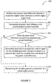
Figure 2 is a flowchart illustrating an example method for controlling the engine ofFIG. 1 , in accordance with an illustrative embodiment; -
Figure 3 is an example graphical representation of a requisite bias scaling factor; -
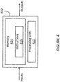
Figure 4 is a block diagram of an example computer system for implementing the method ofFigure 2 ; and -
Figure 5 is a block diagram of an example engine system. - It will be noted that throughout the appended drawings, like features are identified by like reference numerals.
-
Figure 1 illustrates agas turbine engine 10 of a type preferably provided for use in subsonic flight, generally comprising in serial flow communication anair inlet 11, acompressor section 12 for pressurizing the air from theair inlet 11, acombustor 13 in which the compressed air is mixed with fuel and ignited for generating an annular stream of hot combustion gases, aturbine section 14 for extracting energy from the combustion gases, and anexhaust outlet 15 through which the combustion gases exit thegas turbine engine 10. Theengine 10 includes apropeller 16 which provides thrust for flight and taxiing. Thegas turbine engine 10 has alongitudinal center axis 17. - The gas turbine engine 10 (sometimes referred to herein simply as "
engine 10") has acentral core 18 defining a gas path through which gases flow as depicted by flow arrows inFig. 1 . The exemplifiedengine 10 is a "reverse-flow"engine 10 because gases flow through thecore 18 from theair inlet 11 at a rear portion thereof, to theexhaust outlet 15 at a front portion thereof. This is in contrast to "through-flow" gas turbine engines in which gases flow through the core of the engine from a front portion to a rear portion. The direction of the flow of gases through thecore 18 of theengine 10 disclosed herein can be better appreciated by considering that the gases flow through thecore 18 in the same direction D as the one along which theengine 10 travels during flight. Stated differently, gases flow through theengine 10 from a rear end thereof towards thepropeller 16. - Although illustrated as a turboprop engine, the
gas turbine engine 10 may alternatively be another type of engine, for example a turbofan engine, also generally comprising in serial flow communication a compressor section, a combustor, and a turbine section, and a fan through which ambient air is propelled. A turboshaft engine may also apply. In addition, although theengine 10 is described herein for flight applications, it should be understood that other uses, such as industrial or the like, may apply. - Still referring to
Figure 1 , theengine 10 has multiple spools which perform compression to pressurize the air received through theair inlet 11, and which extract energy from the combustion gases before they exit thecore 18 via theexhaust outlet 15. According to the illustrated example, theengine 10 is provided in the form of a multi-spool engine having a low pressure (LP)spool 20 and a high pressure (HP)spool 40 independently rotatable aboutaxis 17. However, it is understood that a multi-spool engine could have more than two spools. It should also be noted that the embodiments described herein also consider the use of single-spool engines. - The
LP spool 20 includes at least one component to compress the air that is part of thecompressor section 12, and at least one component to extract energy from the combustion gases that is part of theturbine section 14. More particularly, theLP spool 20 has alow pressure turbine 21 which extracts energy from the combustion gases, and which is drivingly engaged to anLP compressor 22 for pressurizing the air. The LP turbine 21 (also referred to as the power turbine) drives theLP compressor 22, thereby causing theLP compressor 22 to pressurize the air. Both theLP turbine 21 and theLP compressor 22 are disposed along theaxis 17. In the depicted embodiment, both theLP turbine 21 and theLP compressor 22 are axial rotatable components having an axis of rotation that is coaxial with thecenter axis 17. They can include one or more stages, depending upon the desired engine thermodynamic cycle, for example. - In the depicted embodiment, the
LP spool 20 has apower shaft 23 which mechanically couples theLP turbine 21 and theLP compressor 22, and extends axially between them. Theshaft 23 is coaxial with thecentral axis 17 of theengine 10. Theshaft 23 allows theLP turbine 21 to drive theLP compressor 22 during operation of theengine 10. Theshaft 23 is not limited to the configuration depicted inFig. 1 , and can also mechanically couple theLP turbine 21 and theLP compressor 22 in any other suitable way provided that it transmits a rotational drive from theLP turbine 21 to theLP compressor 22. For example, theshaft 23 can be combined with a gearedLP compressor 22 to allow theLP compressor 22 to run at a different rotational speed from theLP turbine 21. This can provide more flexibility in the selection of design points for the LP compressor. - Still referring to
Figure 1 , theengine 10 includes anoutput drive shaft 24. Thedrive shaft 24 extends forwardly from theLP turbine 21 and is drivingly engaged thereto. In the illustrated example, thedrive shaft 24 is distinct from thepower shaft 23 and mechanically coupled thereto to be driven by theLP turbine 21. In the depicted embodiment, thedrive shaft 24 and thepower shaft 23 are coaxial and interconnected.Figure 1 shows that the power and driveshafts spline 25. Thespline 25, which can include ridges or teeth on thedrive shaft 24 that mesh with grooves in the power shaft 23 (or vice versa), allows for the transfer of torque between thedrive shaft 24 and thepower shaft 23. In the depicted embodiment, thepower shaft 23 lies at least partially within thedrive shaft 24, such that thespline 25 transfers the rotational drive or torque generated by theLP turbine 21 from thedrive shaft 24 to thepower shaft 23. Thespline 25 can operate so that thepower shaft 23 and thedrive shaft 24 rotate at the same rotational speed. Other mechanical techniques can also be used to interconnect the power and driveshafts shafts drive shaft 24 and thepower shaft 23 are also possible. For example, thedrive shaft 24 and thepower shaft 23 can be a single shaft driven by theLP turbine 21. Thedrive shaft 24 therefore transfers the rotational output of theLP turbine 21 in a forward direction to drive another component. - A rotatable load, which in the embodiment shown includes the
propeller 16, is mountable to theengine 10, and when mounted, is drivingly engaged to theLP turbine 21, and is located forward of theLP turbine 21. In such a configuration, during operation of theengine 10, theLP turbine 21 drives the rotatable load such that a rotational drive produced by theLP turbine 21 is transferred to the rotatable load. The rotatable load can therefore be any suitable component, or any combination of suitable components, that is capable of receiving the rotational drive from theLP turbine 21, as now described. - In the embodiment shown, a reduction gearbox 31 (sometimes referred to herein simply as "
RGB 31") is mechanically coupled to a front end of thedrive shaft 24, which extends between theRGB 31 and theLP turbine 21. TheRGB 31 processes and outputs the rotational drive transferred thereto from theLP turbine 21 via thedrive shaft 24 through known gear reduction techniques. TheRGB 31 allows for thepropeller 16 to be driven at its optimal rotational speed, which is different from the rotational speed of theLP turbine 21. - Still referring to
Figure 1 , theHP spool 40 with at least one component to compress the air that is part of thecompressor section 12, and at least one component to extract energy from the combustion gases that is part of theturbine section 14. TheHP spool 40 is also disposed along theaxis 17 and includes anHP turbine 41 drivingly engaged (e.g. directly connected) to a high pressure compressor 42 by anHP shaft 43 rotating independently of thepower shaft 23. Similarly to theLP turbine 21 and theLP compressor 22, theHP turbine 41 and the HP compressor 42 can include various stages of axial rotary components. In the depicted embodiment, the HP compressor 42 includes acentrifugal compressor 42A or impeller and anaxial compressor 42B, both of which are driven by theHP turbine 41. During operation of theengine 10, theHP turbine 41 drives the HP compressor 42. - It can thus be appreciated that the presence of the above-described LP and HP spools 20, 40 provides the
engine 10 with a "split compressor" arrangement. More particularly, some of the work required to compress the incoming air is transferred from the HP compressor 42 to theLP compressor 22. In other words, some of the compression work is transferred from theHP turbine 41 to the moreefficient LP turbine 21. This transfer of work may contribute to higher pressure ratios while maintaining a relatively small number of rotors. In a particular embodiment, higher pressure ratios allow for higher power density, better engine specific fuel consumption (SFC), and a lower turbine inlet temperature (sometimes referred to as "T4") for a given power. These factors can contribute to a lower overall weight for theengine 10. The transfer of compression work from the HP compressor 42 to theLP compressor 22 contrasts with some conventional reverse-flow engines, in which the high pressure compressor (and thus the high pressure turbine) perform all of the compression work. - In light of the preceding, it can be appreciated that the
LP turbine 21 is the "low-speed" and "low pressure" turbine when compared to theHP turbine 41. TheLP turbine 21 is sometimes referred to as a "power turbine". The turbine rotors of theHP turbine 41 spin at a higher rotational speed than the turbine rotors of theLP turbine 21 given the closer proximity of theHP turbine 41 to the outlet of thecombustor 13. Consequently, the compressor rotors of the HP compressor 42 may rotate at a higher rotational speed than the compressor rotors of theLP compressor 22. Theengine 10 shown inFig. 1 is thus a "two-spool"engine 10. - The
HP turbine 41 and the HP compressor 42 can have any suitable mechanical arrangement to achieve the above-described split compressor functionality. For example, and as shown inFig. 1 , theHP spool 40 includes ahigh pressure shaft 43 extending between the HP compressor 42 and theHP turbine section 41. Thehigh pressure shaft 43 is coaxial with thepower shaft 23 and rotatable relative thereto. The relative rotation between thehigh pressure shaft 43 and thepower shaft 23 allow theshafts LP compressor 22 to rotate at different rotational speeds. TheHP shaft 43 can be mechanically supported by thepower shaft 23 using bearings or the like. In the depicted embodiment, thepower shaft 23 is at least partially disposed within theHP shaft 43. - The split compressor arrangement also allows bleed air to be drawn from between the HP compressor 42 and the
LP compressor 22. More particularly, in the embodiment ofFig. 1 , theengine 10 includes aninter-stage bleed 44 port or valve that is aft of the HP compressor 42 and forward of theLP compressor 22, which may provide for increased flexibility in the available bleed pressures. In a particular embodiment, the bleed pressure design point of theinter-stage bleed 44 is selected based on the pressure ratio of theLP compressor 22, which runs independently from the HP compressor 42. For operability, variable inlet guide vanes (VIGV) 51 and variable guide vanes (VGV) 52 can be used on theLP compressor 22 and at the entry of the HP compressor 42, together with theinter-stage bleed 44. - It should be noted that the engine of
Figure 1 represents only one example engine, and that the embodiments described herein can be applied to any other suitable manner of engine. - In some embodiments, the
engine 10 includes one or more variable geometry mechanisms (VGMs) which may assist in achieving optimized engine transient response. In some embodiments, the VGMs consist of one or more VGVs, for instance theVIGV 51 and/or theVGV 52, which may be one of inlet compressor guide vanes for directing air into thecompressor section 12, outlet guide vanes for directing air out of thecompressor section 12, variable stator vanes for directing incoming air into rotor blades of theengine 10, and/or one or more variable nozzles, variable bleed-off valves, for instance theinter-stage bleed 44, and the like, or any suitable combination thereof. It should be understood that one or more of the above-mentioned VGMs may be adjusted for the purpose of decreasing the response time of theengine 10 during rapid engine transitions, e.g. from low to high power levels, or vice-versa. Indeed, adjustment of the position (e.g. the angle) of the VGMs can impact the inlet mass flow to theengine 10, and in turn allow theengine 10 to operate at a required power. - In some embodiments, as illustrated in
Figure 1 , theengine 10 has a dual compression system with a low-spool compression system (LPC), including theLP spool 20, and a high-spool compression system (HPC), including theHP spool 40, which are separate from one-another. The VGMs include theVIGV 51 at theair inlet 11 near the LPC and theVGV 52 upstream of the HPC. In other embodiments, theengine 10 includes only one compression system, and includes fewer or more variable geometry mechanisms. - With reference to
Figure 2 , there is illustrated a flowchart of anexample method 200 for controlling an engine, for example theengine 10, which may be a part of an aircraft. Atstep 202, a power level difference between a requested engine power level and a current engine power level is determined. In some embodiments, the requested engine power level is obtained when a request to alter the engine's power is provided, for example from an operator of the aircraft via one or more controls. The controls may include levers, pedals, switches, touchscreen-based controls, and the like. The requested engine power level may be obtained in any suitable format, including as a percent-change vis-a-vis a current engine power level, an absolute power level, a relative power level expressed as a portion of a maximum, and the like. In some embodiments, themethod 200 is triggered to begin upon obtaining the requested engine power level for theengine 10. For example, a pilot or other operator of the aircraft may produce a requested engine power level via a thrust lever, which causes themethod 200 to be commenced. In some embodiments, the requested power engine level is obtained via a digital power demand system. In other embodiments, the requested engine power level is obtained via a power setting map. In still further embodiments, the requested engine power level is estimated based on one or more inputs from a pilot or operator of the aircraft, and/or based on information acquired from one or more sensors in theengine 10 and/or the aircraft to which theengine 10 belongs. - In some embodiments, the current engine power level is obtained from a sensor or control system. In other embodiments, the current engine power level is estimated based on one or more readings obtained from sensors and the like. In still further embodiments, the current engine power level is substantially continuously monitored, and a value for the current engine power level at or near a time at which the requested engine power level is obtained is used for comparison purposes. In some embodiments, the power level is a thrust level for the
engine 10; in other embodiments, a speed of theengine 10 is used as a proxy for the power level, or is used to derive or estimate the power level. - The difference between the current engine power level and the requested engine power level may be determined in any suitable way, using any suitable techniques. In some embodiments, the power level difference is a percent difference vis-à-vis the current engine power level, for example a percent increase or a percent decrease. In other embodiments, the power level difference is a value scaled to a particular maximum power level, or a reference power level which may be associated with one or more particular operating conditions or ratings of the
engine 10. Still other methods of expressing the power level difference are considered, for example in absolute numbers, normalized numbers, and the like. In one particular embodiment, the power level difference is defined by
engine 10 during takeoff for the aircraft. - At
step 204, the power level difference is compared to a predetermined power threshold. In some embodiments, the predetermined power threshold is obtained from a control system, or is determined based on one or more factors, for example one or more operating conditions of theengine 10. In some embodiments, the predetermined power threshold is based on a reference power level for the operating conditions of theengine 10. For example, a cruise flight condition is associated with a first reference power level, and a descent flight condition is associated with a second reference power level. - The comparison of the power level difference against the predetermined power threshold may be performed in any suitable way, using any suitable techniques. In some embodiments, different power thresholds are provided for each of positive and negative power level differences. For example, the power level difference is compared against a positive power threshold when the power level difference is positive (i.e. above 0), and against a negative power threshold when the power level difference is negative (i.e. below 0). In some embodiments, the positive and the negative power thresholds are determined independently from one another.
- At
decision 206, a determination is made regarding whether the power level difference exceeds the predetermined power threshold. In the affirmative case, themethod 200 moves to step 208. In the negative case, themethod 200 proceeds to step 210, described in greater detail hereinbelow. - In embodiments where positive and negative power thresholds are provided, the power level difference exceeding the predetermined power threshold may be evaluated as an absolute value. For example, the determination of whether a negative power level difference exceeds the negative power threshold is based on the absolute value of both the negative power level difference and the negative power threshold.
- At
step 208, a position control signal for the variable geometry mechanism is generated and output, based on a requisite bias level, which is based on the power level difference. The position control signal may be any suitable type of signal, encoded in any suitable format, and may be transmitted using any suitable communication medium. In some embodiments, the position control signal is output to theengine 10, or to a controller thereof, to cause a change in the position of the variable geometry mechanism. In other embodiments, the position control signal is output to the variable geometry mechanism itself. - The requisite bias level is indicative of a required change in the position of the variable geometry mechanisms of the
engine 10, for example one or more of theVIGVs 51 and theVGV 52. In some embodiments, the requisite bias level is determined by scaling the power level difference by a factor associated with a maximum bias level. The factor may be based on the maximum bias level itself, on the maximum bias level and a reference power level associated with the operating condition of theengine 10, or with any other suitable parameters of theengine 10 and/or the aircraft. For example, the requisite bias level is determined as a change from a steady-state bias level, that is to say a current bias level which is maintained when the position of the variable geometry mechanisms of theengine 10 is not changed. In some embodiments, the requisite bias level is determined by the following equation
engine 10. In some embodiments, the maximum bias level B max is obtained based on the operating condition of theengine 10, for example a power level for theengine 10. In some embodiments, the steady-state bias level BSS is obtained from a schedule or lookup table. - At
step 210, following the determination that the power level difference does not exceed the predetermined power threshold, the variable geometry mechanism is maintained at a steady-state position, that is to say that the variable geometry mechanisms are maintained in a current or existing position. In some embodiments, the variable geometry mechanism is configured for maintaining the steady-state position absent any input from a control system or the like. In other embodiments, a steady-state position control signal is generated and output to indicate to the variable geometry mechanism that the steady-state position is to be maintained. The steady-state position control signal may be substantially similar to the position control signal discussed hereinabove, but indicating that the variable geometry mechanism is to maintain the steady-state position. In some embodiments, the position control signal is output to theengine 10, or to a controller thereof, to cause the variable geometry mechanism to maintain the steady-state position. In other embodiments, the position control signal is output to the variable geometry mechanism itself. - In this fashion, requests to change the power level of the
engine 10, in the form of newly-obtained requested engine power levels, only cause changes to the position of the variable geometry mechanism when the power level difference exceeds the predetermined power threshold. This may be used to avoid changes to the position of the variable geometry mechanism in response to minor changes in engine power levels, which may not warrant commensurate changes in the position of the variable geometry mechanism, while maintaining such commensurate changes when the power level difference is significant enough, i.e. exceeding the predetermined power threshold. - In some embodiments, the predetermined power threshold is based on a percent-difference from the reference power level. For example, the predetermined power threshold is set at a 5% variation from the reference power level, or a 7% variation, or a 10% variation, or any other suitable percent-difference. In some embodiments, the percent-difference is made variable on one or more operating conditions of the
engine 10 and/or one or more environmental conditions in which theengine 10 is operating. - With reference to
Figure 3 , the scaling factor K is used to scale the requisite bias level based on the power difference, as illustrated bycurve 302. The predetermined power thresholds are indicated bycutoff lines cutoff lines cutoff lines - With reference to
Figure 4 , themethod 200 may be implemented by acomputing device 410, comprising aprocessing unit 412 and amemory 414 which has stored therein computer-executable instructions 416. Theprocessing unit 412 may comprise any suitable devices configured to implement themethod 200 such thatinstructions 416, when executed by thecomputing device 410 or other programmable apparatus, may cause the functions/acts/steps performed as part of themethod 200 as described herein to be executed. Theprocessing unit 412 may comprise, for example, any type of general-purpose microprocessor or microcontroller, a digital signal processing (DSP) processor, a central processing unit (CPU), an integrated circuit, a field programmable gate array (FPGA), a reconfigurable processor, other suitably programmed or programmable logic circuits, or any combination thereof. - The
memory 414 may comprise any suitable known or other machine-readable storage medium. Thememory 414 may comprise non-transitory computer readable storage medium, for example, but not limited to, an electronic, magnetic, optical, electromagnetic, infrared, or semiconductor system, apparatus, or device, or any suitable combination of the foregoing. Thememory 414 may include a suitable combination of any type of computer memory that is located either internally or externally to device, for example random-access memory (RAM), read-only memory (ROM), compact disc read-only memory (CDROM), electro-optical memory, magnetooptical memory, erasable programmable read-only memory (EPROM), and electrically-erasable programmable read-only memory (EEPROM), Ferroelectric RAM (FRAM) or the like.Memory 414 may comprise any storage means (e.g., devices) suitable for retrievably storing machine-readable instructions 416 executable by processingunit 412. - With reference to
Figure 5 , in some embodiments theengine 10 is part of anengine system 500 of an aircraft. Theengine system 500 additionally includes aVGM control module 510, acomparator 520, and apower module 530. Theengine 10 is communicatively coupled to theVGM control module 510 and optionally to thecomparator 520. TheVGM control module 510 is coupled to thecomparator 520, which in turn is coupled to thepower module 530. - As described hereinabove, in some embodiments the
engine 10 includes one or more variable geometry mechanisms, illustrated here asVGMs 130. It should be noted that theVGMs 130 may include one or more VIGVs, for instance theVIGVs 51, one or more VGVs, for instance theVGVs 52, variable stator vanes, variable nozzles, variable bleed-off valves, and the like. Theengine 10 is configured for producing power at a current engine power level, and is configured to report the current engine power level of theengine 10 to theVGM control module 510. Optionally, theengine 10 reports the current engine power level to thecomparator 520. - The
power module 530 is configured for obtaining signals indicative of requested changes in the power level of theengine 10 from one or more control systems and/or input devices. In some embodiments, thepower module 530 receives inputs from a pilot or other operator of the aircraft provided via a thrust lever or other operator control. Thepower module 530 is configured for providing a requested engine power level to thecomparator 520. In some embodiments, the signals received at thepower module 530 are already indicative of the requested engine power level, and thepower module 530 provides the requested engine power level to thecomparator 520. In other embodiments, the signals received at thepower module 530 are used to estimate or otherwise derive therefrom the requested engine power level. - The
comparator 520 is configured for determining the power level difference between the requested engine power level and the current engine power level, as perstep 202. In some embodiments, thecomparator 520 obtains the current engine power level from theengine 10 via theVGM control module 510. In other embodiments, thecomparator 520 obtains the current engine power level from theengine 10 substantially directly. In some embodiments, thecomparator 520 collaborates with thepower module 530 to obtain the requested power level, for example when the requested power level is estimated based on other information. - The
comparator 520 is further configured for comparing the power level difference to the predetermined power threshold, as perstep 204. In some embodiments, thecomparator 520 is configured for determining the predetermined power threshold based on an operating condition of theengine 10, which may be obtained from theengine 10 via theVGM control module 510 or substantially directly. In other embodiments, thecomparator 520 determines the predetermined power threshold via one or more lookup tables, databases, and the like. In embodiments where different predetermined power thresholds exist for positive and negative power level differences, thecomparator 520 is configured for comparing the power level difference with the appropriate predetermined power threshold. For example, thecomparator 520 may compare an absolute value of the power level difference to the negative predetermined power threshold. - The
comparator 520 is additionally configured for implementingdecision step 208. Thecomparator 520 is thus configured to communicate the result of the comparison between the power level difference and the predetermined power threshold to theVGM control module 510. In some embodiments, thecomparator 520 provides theVGM control module 510 with an indication of the comparison. In other embodiments, thecomparator 520 instructs theVGM control module 510 on which ofsteps 210 and 222 should be implemented by theVGM control module 510. - When the power difference exceeds the predetermined power threshold, the
VGM control module 510 is configured for determining the requisite bias level for theVGMs 130 based on the power level difference, as perstep 210. TheVGM control module 510 may use any suitable lookup tables, algorithms, and the like to determine the requisite bias level. In some embodiments, determining the requisite bias level comprises scaling the power level difference by a factor associated with the maximum bias level and/or the reference power level, which may be based on operating conditions of the aircraft. In some embodiments, theVGM control module 510 is configured for obtaining and/or determining the maximum bias level based on the operating conditions of the aircraft. - The
VGM control module 510 is further configured for generating and outputting a position control signal for theVGMs 130, based on the requisite bias level, as per step 212. The position control signal may be any suitable type of signal, encoded in any suitable format, and may be transmitted using any suitable communication medium to theengine 10, and in certain embodiments to theVGMs 130. - When the power difference does not exceed the predetermined power threshold, the
VGM control module 510 is configured for maintaining theVGM 130 at the steady-state position, as per step 222. In some embodiments, theVGM control module 510 sends a steady-state position control signal to theengine 10, and in some instances theVGMs 130, to maintain theVGMs 130 at the steady-state position. - It should be noted that the
VGM control module 510, and any other suitable elements of theengine system 500, may be implemented as part of a full-authority digital engine controls (FADEC) or other similar device, including electronic engine control (EEC), engine control unit (EUC), various actuators, and the like. - The methods and systems for controlling an engine described herein may be implemented in a high level procedural or object oriented programming or scripting language, or a combination thereof, to communicate with or assist in the operation of a computer system, for example the
computing device 410. Alternatively, the methods and systems for controlling an engine may be implemented in assembly or machine language. The language may be a compiled or interpreted language. Program code for implementing the methods and systems for controlling an engine may be stored on a storage media or a device, for example a ROM, a magnetic disk, an optical disc, a flash drive, or any other suitable storage media or device. The program code may be readable by a general or special-purpose programmable computer for configuring and operating the computer when the storage media or device is read by the computer to perform the procedures described herein. Embodiments of the methods and systems for controlling an engine may also be considered to be implemented by way of a non-transitory computer-readable storage medium having a computer program stored thereon. The computer program may comprise computer-readable instructions which cause a computer, or more specifically theprocessing unit 412 of thecomputing device 410, to operate in a specific and predefined manner to perform the functions described herein, for example those described in themethod 200. - Computer-executable instructions may be in many forms, including program modules, executed by one or more computers or other devices. Generally, program modules include routines, programs, objects, components, data structures, etc., that perform particular tasks or implement particular abstract data types. Typically the functionality of the program modules may be combined or distributed as desired in various embodiments.
- The above description is meant to be exemplary only, and one skilled in the art will recognize that changes may be made to the embodiments described without departing from the scope of the invention disclosed. Still other modifications which fall within the scope of the present invention will be apparent to those skilled in the art, in light of a review of this disclosure.
- Various aspects of the methods and systems for controlling an engine may be used alone, in combination, or in a variety of arrangements not specifically discussed in the embodiments described in the foregoing and is therefore not limited in its application to the details and arrangement of components set forth in the foregoing description or illustrated in the drawings. For example, aspects described in one embodiment may be combined in any manner with aspects described in other embodiments. Although particular embodiments have been shown and described, it will be apparent to those skilled in the art that changes and modifications may be made without departing from this invention in its broader aspects. The scope of the following claims should not be limited by the embodiments set forth in the examples, but should be given the broadest reasonable interpretation consistent with the description as a whole.
Claims (15)
- A method for controlling an engine (10) having a variable geometry mechanism (51, 52; 130), comprising:determining, at a computing device (410), a power level difference between a requested engine power level and a current engine power level;comparing, at the computing device (410), the power level difference to a predetermined power threshold; andwhen the power level difference exceeds the predetermined power threshold, generating and outputting, at the computing device (410), a position control signal for changing a position of the variable geometry mechanism (51, 52; 130), the position control signal generated based on a requisite bias level, the requisite bias level based on the power level difference.
- The method of claim 1, further comprising, when the power level difference does not exceed the predetermined power threshold, maintaining the variable geometry mechanism (51, 52; 130) at a steady-state position.
- The method of claim 2, wherein the position control signal is a first position control signal, and maintaining the variable geometry mechanism (51, 52; 130) at the steady-state position comprises generating and outputting a second position control signal for the variable geometry mechanism (51, 52; 130) based on an operating condition of the engine (10).
- The method of claim 1, 2 or 3, further comprising determining, at the computing device (410), the requisite bias level by scaling the power level difference by a factor associated with a maximum bias level, and optionally further comprising determining, at the computing device (410), the maximum bias level based on a or the operating condition of the engine (10), wherein, further optionally, scaling the power level difference by the factor comprises determining the factor based on the maximum bias level and a reference power level associated with the operating condition of the engine (10).
- The method of any preceding claim, wherein the predetermined power threshold is related to a reference power level associated with a or the operating condition of the engine (10).
- The method of any preceding claim, further comprising determining, at the computing device (410), the predetermined power threshold based on a or the operating condition of the engine (10).
- The method of any preceding claim, wherein obtaining the requested engine power level comprises estimating the requested engine power level.
- The method of any preceding claim, wherein the predetermined power threshold comprises a positive power threshold and a negative power threshold, and comparing the power level difference to the predetermined power threshold comprises comparing the power level difference to the positive power threshold when the power level difference is positive and comparing the power level difference to the negative power threshold when the power level difference is negative.
- An engine control system for a variable geometry mechanism (51, 52; 130), comprising:a processing unit (412); anda non-transitory computer-readable memory (414) communicatively coupled to the processing unit (412) and comprising computer-readable program instructions (416) executable by the processing unit (412) for:determining a power level difference between a requested engine power level and a current engine power level;comparing the power level difference to a predetermined power threshold; andwhen the power level difference exceeds the predetermined power threshold, generating and outputting a position control signal for changing a position of the variable geometry mechanism (51, 52; 130), the position control signal generated based on a requisite bias level, the requisite bias level based on the power level difference.
- The system of claim 9, wherein the computer-readable program instructions (416) are further executable by the processing unit (412) for, when the power level difference does not exceed the predetermined power threshold, maintaining the variable geometry mechanism (51, 52; 130) at a steady-state position.
- The system of claim 10, wherein the position control signal is a first position control signal, and maintaining the variable geometry mechanism (51, 52; 130) at the steady-state position comprises generating and outputting a second position control signal for the variable geometry mechanism (51, 52; 130) based on an operating condition of the engine (10).
- The system of claim 9, 10 or 11, wherein determining the requisite bias level comprises scaling the power level difference by a factor associated with a maximum bias level, wherein, optionally, the computer-readable program instructions (416) are further executable by the processing unit (412) for determining the maximum bias level based on a or the operating condition of the engine (10), and wherein, further optionally, scaling the power level difference by the factor comprises determining the factor based on the maximum bias level and a reference power level associated with the operating condition of the engine (10).
- The system of any of claims 9 to 12, wherein the predetermined power threshold is related to a reference power level associated with a or the operating condition of the engine (10).
- The system of any one of claims 9 to 13, wherein the computer-readable program instructions (416) are further executable by the processing unit (412) for determining the predetermined power threshold based on a or the operating condition of the engine (10).
- The system of any of claims 9 to 14, wherein obtaining the requested engine power level comprises estimating the requested engine power level.
Applications Claiming Priority (1)
| Application Number | Priority Date | Filing Date | Title |
|---|---|---|---|
| US201762551429P | 2017-08-29 | 2017-08-29 |
Publications (2)
| Publication Number | Publication Date |
|---|---|
| EP3450729A1 true EP3450729A1 (en) | 2019-03-06 |
| EP3450729B1 EP3450729B1 (en) | 2024-04-24 |
Family
ID=63556126
Family Applications (1)
| Application Number | Title | Priority Date | Filing Date |
|---|---|---|---|
| EP18191565.3A Active EP3450729B1 (en) | 2017-08-29 | 2018-08-29 | Variable geometries transient control logic |
Country Status (4)
| Country | Link |
|---|---|
| US (1) | US10822104B2 (en) |
| EP (1) | EP3450729B1 (en) |
| CA (1) | CA3015559A1 (en) |
| PL (1) | PL3450729T3 (en) |
Cited By (2)
| Publication number | Priority date | Publication date | Assignee | Title |
|---|---|---|---|---|
| EP3910180A1 (en) * | 2020-05-13 | 2021-11-17 | Safran Aero Boosters SA | Transient opening of stator blades in a turbine engine compressor during an acceleration |
| EP4141241A1 (en) * | 2021-08-13 | 2023-03-01 | Pratt & Whitney Canada Corp. | Method and system for operating an engine to generate additional thrust |
Families Citing this family (3)
| Publication number | Priority date | Publication date | Assignee | Title |
|---|---|---|---|---|
| US9733091B2 (en) * | 2007-05-31 | 2017-08-15 | Trx Systems, Inc. | Collaborative creation of indoor maps |
| US10968765B2 (en) * | 2018-12-04 | 2021-04-06 | General Electric Company | Power system with a coordinated power draw |
| US11554874B2 (en) * | 2020-10-02 | 2023-01-17 | Pratt & Whitney Canada Corp. | Method and system for governing an engine at low power |
Citations (4)
| Publication number | Priority date | Publication date | Assignee | Title |
|---|---|---|---|---|
| US4370560A (en) * | 1979-10-15 | 1983-01-25 | Sundstrand Corporation | Compressor load control for an auxiliary power unit |
| US20100281875A1 (en) * | 2006-10-13 | 2010-11-11 | Brian John Price | Dynamic control of a gas turbine engine compressor during rapid transients |
| US20130038072A1 (en) * | 2011-08-08 | 2013-02-14 | General Electric Company | System and method for hot ambient and grid frequency compensation for a gas turbine |
| US20130236296A1 (en) * | 2012-03-09 | 2013-09-12 | Pratt & Whitney | Low Pressure Compressor Variable Vane Control for Two-Spool Turbofan or Turboprop Engine |
Family Cites Families (13)
| Publication number | Priority date | Publication date | Assignee | Title |
|---|---|---|---|---|
| GB2119862A (en) | 1982-05-06 | 1983-11-23 | Gen Electric | Variable stator vane (VSV) closed loop control system of a compressor |
| US6735955B2 (en) | 2001-10-10 | 2004-05-18 | Goodrich Pump & Engine Control Systems, Inc. | Control system for positioning compressor inlet guide vanes |
| ES2571212T3 (en) | 2009-07-21 | 2016-05-24 | Alstom Technology Ltd | Method for the control of gas turbine engines |
| FR2950927B1 (en) | 2009-10-06 | 2016-01-29 | Snecma | SYSTEM FOR CONTROLLING THE ANGULAR POSITION OF STATOR AUBES AND METHOD FOR OPTIMIZATION OF SAID ANGULAR POSITION |
| US8909454B2 (en) | 2011-04-08 | 2014-12-09 | General Electric Company | Control of compression system with independently actuated inlet guide and/or stator vanes |
| US20140053567A1 (en) | 2012-08-22 | 2014-02-27 | Fritz Langenbacher | System and method for controlling a gas turbine engine generator set |
| US9540944B2 (en) | 2012-09-28 | 2017-01-10 | United Technologies Corporation | Real time model based compressor control |
| US9322341B2 (en) * | 2013-03-12 | 2016-04-26 | Pratt & Whitney Canada Corp. | System and method for engine transient power response |
| US10113487B2 (en) * | 2013-10-24 | 2018-10-30 | United Technologies Corporation | Cascaded multi-variable control system for a turboshaft engine |
| US9850823B2 (en) | 2013-12-26 | 2017-12-26 | Siemens Aktiengesellschaft | Control system and method for controlling a gas turbine engine during transients |
| US9494085B2 (en) | 2015-01-19 | 2016-11-15 | United Technologies Corporation | System and method for load power management in a turboshaft gas turbine engine |
| US9732625B2 (en) | 2015-01-19 | 2017-08-15 | United Technologies Corporation | System and method for controlling a gas turbine engine |
| GB201601427D0 (en) | 2016-01-26 | 2016-03-09 | Rolls Royce Plc | Setting control for gas turbine engine component(s) |
-
2018
- 2018-08-23 US US16/110,699 patent/US10822104B2/en active Active
- 2018-08-27 CA CA3015559A patent/CA3015559A1/en active Pending
- 2018-08-29 PL PL18191565.3T patent/PL3450729T3/en unknown
- 2018-08-29 EP EP18191565.3A patent/EP3450729B1/en active Active
Patent Citations (4)
| Publication number | Priority date | Publication date | Assignee | Title |
|---|---|---|---|---|
| US4370560A (en) * | 1979-10-15 | 1983-01-25 | Sundstrand Corporation | Compressor load control for an auxiliary power unit |
| US20100281875A1 (en) * | 2006-10-13 | 2010-11-11 | Brian John Price | Dynamic control of a gas turbine engine compressor during rapid transients |
| US20130038072A1 (en) * | 2011-08-08 | 2013-02-14 | General Electric Company | System and method for hot ambient and grid frequency compensation for a gas turbine |
| US20130236296A1 (en) * | 2012-03-09 | 2013-09-12 | Pratt & Whitney | Low Pressure Compressor Variable Vane Control for Two-Spool Turbofan or Turboprop Engine |
Cited By (4)
| Publication number | Priority date | Publication date | Assignee | Title |
|---|---|---|---|---|
| EP3910180A1 (en) * | 2020-05-13 | 2021-11-17 | Safran Aero Boosters SA | Transient opening of stator blades in a turbine engine compressor during an acceleration |
| BE1028302B1 (en) * | 2020-05-13 | 2021-12-16 | Safran Aero Boosters | TRANSIENT OPENING OF STATOR BLADE IN A TURBOMACHINE COMPRESSOR DURING ACCELERATION |
| EP4141241A1 (en) * | 2021-08-13 | 2023-03-01 | Pratt & Whitney Canada Corp. | Method and system for operating an engine to generate additional thrust |
| US11732657B2 (en) | 2021-08-13 | 2023-08-22 | Pratt & Whitney Canada Corp. | Methods and systems for operating an engine to generate additional thrust |
Also Published As
| Publication number | Publication date |
|---|---|
| PL3450729T3 (en) | 2024-07-01 |
| US10822104B2 (en) | 2020-11-03 |
| US20190061969A1 (en) | 2019-02-28 |
| CA3015559A1 (en) | 2019-02-28 |
| EP3450729B1 (en) | 2024-04-24 |
Similar Documents
| Publication | Publication Date | Title |
|---|---|---|
| US12116940B2 (en) | Corrected parameters control logic for variable geometry mechanisms | |
| EP3450729B1 (en) | Variable geometries transient control logic | |
| CA2976984C (en) | Shaft event detection in gas turbine engines | |
| US8887485B2 (en) | Three spool gas turbine engine having a clutch and compressor bypass | |
| JP2733503B2 (en) | Gas turbine engine transient control system. | |
| EP2884075B1 (en) | Aircraft engine system comprising a main engine, a starter and an auxiliary power unit | |
| EP3530910B1 (en) | Method and apparatus for controlling at least a part of a start-up or re-light process of a gas turbine engine | |
| EP3626946B1 (en) | Signal processing for variable geometry mechanism control | |
| JP5405026B2 (en) | Method for extracting auxiliary power from an aircraft turbojet and turbojet installed to implement the method | |
| EP3282093A1 (en) | Geared turbofan with low spool power extraction | |
| CN109312665B (en) | Fuel delivery system and method for gas turbine engine | |
| US11668253B2 (en) | System and method for providing in-flight reverse thrust for an aircraft | |
| EP2924247B1 (en) | Hybrid drive for gas turbine engine | |
| EP2902608A1 (en) | Aft shrouded geared turbofan | |
| EP3633167A1 (en) | Corrected fuel-flow-rate-based control for variable geometry mechanisms | |
| CA3073692C (en) | Systems and methods for control of engine variable geometry mechanism | |
| CN118327786A (en) | High pressure rotor control system | |
| EP3741665B1 (en) | Method and system for operating an aircraft powerplant | |
| EP3835564A1 (en) | Systems and methods for operating an engine having variable geometry mechanisms | |
| GB2589374A (en) | Electronic engine controller |
Legal Events
| Date | Code | Title | Description |
|---|---|---|---|
| PUAI | Public reference made under article 153(3) epc to a published international application that has entered the european phase |
Free format text: ORIGINAL CODE: 0009012 |
|
| STAA | Information on the status of an ep patent application or granted ep patent |
Free format text: STATUS: THE APPLICATION HAS BEEN PUBLISHED |
|
| AK | Designated contracting states |
Kind code of ref document: A1 Designated state(s): AL AT BE BG CH CY CZ DE DK EE ES FI FR GB GR HR HU IE IS IT LI LT LU LV MC MK MT NL NO PL PT RO RS SE SI SK SM TR |
|
| AX | Request for extension of the european patent |
Extension state: BA ME |
|
| STAA | Information on the status of an ep patent application or granted ep patent |
Free format text: STATUS: REQUEST FOR EXAMINATION WAS MADE |
|
| 17P | Request for examination filed |
Effective date: 20190906 |
|
| RBV | Designated contracting states (corrected) |
Designated state(s): AL AT BE BG CH CY CZ DE DK EE ES FI FR GB GR HR HU IE IS IT LI LT LU LV MC MK MT NL NO PL PT RO RS SE SI SK SM TR |
|
| STAA | Information on the status of an ep patent application or granted ep patent |
Free format text: STATUS: EXAMINATION IS IN PROGRESS |
|
| 17Q | First examination report despatched |
Effective date: 20211104 |
|
| GRAP | Despatch of communication of intention to grant a patent |
Free format text: ORIGINAL CODE: EPIDOSNIGR1 |
|
| STAA | Information on the status of an ep patent application or granted ep patent |
Free format text: STATUS: GRANT OF PATENT IS INTENDED |
|
| INTG | Intention to grant announced |
Effective date: 20231123 |
|
| GRAS | Grant fee paid |
Free format text: ORIGINAL CODE: EPIDOSNIGR3 |
|
| GRAA | (expected) grant |
Free format text: ORIGINAL CODE: 0009210 |
|
| STAA | Information on the status of an ep patent application or granted ep patent |
Free format text: STATUS: THE PATENT HAS BEEN GRANTED |
|
| AK | Designated contracting states |
Kind code of ref document: B1 Designated state(s): AL AT BE BG CH CY CZ DE DK EE ES FI FR GB GR HR HU IE IS IT LI LT LU LV MC MK MT NL NO PL PT RO RS SE SI SK SM TR |
|
| REG | Reference to a national code |
Ref country code: GB Ref legal event code: FG4D |
|
| REG | Reference to a national code |
Ref country code: CH Ref legal event code: EP |
|
| REG | Reference to a national code |
Ref country code: DE Ref legal event code: R096 Ref document number: 602018068468 Country of ref document: DE |
|
| REG | Reference to a national code |
Ref country code: IE Ref legal event code: FG4D |
|
| REG | Reference to a national code |
Ref country code: LT Ref legal event code: MG9D |
|
| REG | Reference to a national code |
Ref country code: NL Ref legal event code: MP Effective date: 20240424 |
|
| REG | Reference to a national code |
Ref country code: AT Ref legal event code: MK05 Ref document number: 1679819 Country of ref document: AT Kind code of ref document: T Effective date: 20240424 |
|
| PG25 | Lapsed in a contracting state [announced via postgrant information from national office to epo] |
Ref country code: NL Free format text: LAPSE BECAUSE OF FAILURE TO SUBMIT A TRANSLATION OF THE DESCRIPTION OR TO PAY THE FEE WITHIN THE PRESCRIBED TIME-LIMIT Effective date: 20240424 |
|
| PG25 | Lapsed in a contracting state [announced via postgrant information from national office to epo] |
Ref country code: NL Free format text: LAPSE BECAUSE OF FAILURE TO SUBMIT A TRANSLATION OF THE DESCRIPTION OR TO PAY THE FEE WITHIN THE PRESCRIBED TIME-LIMIT Effective date: 20240424 |
|
| PG25 | Lapsed in a contracting state [announced via postgrant information from national office to epo] |
Ref country code: IS Free format text: LAPSE BECAUSE OF FAILURE TO SUBMIT A TRANSLATION OF THE DESCRIPTION OR TO PAY THE FEE WITHIN THE PRESCRIBED TIME-LIMIT Effective date: 20240824 |
|
| PG25 | Lapsed in a contracting state [announced via postgrant information from national office to epo] |
Ref country code: BG Free format text: LAPSE BECAUSE OF FAILURE TO SUBMIT A TRANSLATION OF THE DESCRIPTION OR TO PAY THE FEE WITHIN THE PRESCRIBED TIME-LIMIT Effective date: 20240424 |
|
| PG25 | Lapsed in a contracting state [announced via postgrant information from national office to epo] |
Ref country code: HR Free format text: LAPSE BECAUSE OF FAILURE TO SUBMIT A TRANSLATION OF THE DESCRIPTION OR TO PAY THE FEE WITHIN THE PRESCRIBED TIME-LIMIT Effective date: 20240424 Ref country code: FI Free format text: LAPSE BECAUSE OF FAILURE TO SUBMIT A TRANSLATION OF THE DESCRIPTION OR TO PAY THE FEE WITHIN THE PRESCRIBED TIME-LIMIT Effective date: 20240424 |
|
| PG25 | Lapsed in a contracting state [announced via postgrant information from national office to epo] |
Ref country code: GR Free format text: LAPSE BECAUSE OF FAILURE TO SUBMIT A TRANSLATION OF THE DESCRIPTION OR TO PAY THE FEE WITHIN THE PRESCRIBED TIME-LIMIT Effective date: 20240725 |
|
| PG25 | Lapsed in a contracting state [announced via postgrant information from national office to epo] |
Ref country code: PT Free format text: LAPSE BECAUSE OF FAILURE TO SUBMIT A TRANSLATION OF THE DESCRIPTION OR TO PAY THE FEE WITHIN THE PRESCRIBED TIME-LIMIT Effective date: 20240826 |
|
| PG25 | Lapsed in a contracting state [announced via postgrant information from national office to epo] |
Ref country code: ES Free format text: LAPSE BECAUSE OF FAILURE TO SUBMIT A TRANSLATION OF THE DESCRIPTION OR TO PAY THE FEE WITHIN THE PRESCRIBED TIME-LIMIT Effective date: 20240424 |
|
| PG25 | Lapsed in a contracting state [announced via postgrant information from national office to epo] |
Ref country code: AT Free format text: LAPSE BECAUSE OF FAILURE TO SUBMIT A TRANSLATION OF THE DESCRIPTION OR TO PAY THE FEE WITHIN THE PRESCRIBED TIME-LIMIT Effective date: 20240424 |
|
| PG25 | Lapsed in a contracting state [announced via postgrant information from national office to epo] |
Ref country code: LV Free format text: LAPSE BECAUSE OF FAILURE TO SUBMIT A TRANSLATION OF THE DESCRIPTION OR TO PAY THE FEE WITHIN THE PRESCRIBED TIME-LIMIT Effective date: 20240424 |
|
| PG25 | Lapsed in a contracting state [announced via postgrant information from national office to epo] |
Ref country code: PT Free format text: LAPSE BECAUSE OF FAILURE TO SUBMIT A TRANSLATION OF THE DESCRIPTION OR TO PAY THE FEE WITHIN THE PRESCRIBED TIME-LIMIT Effective date: 20240826 Ref country code: NO Free format text: LAPSE BECAUSE OF FAILURE TO SUBMIT A TRANSLATION OF THE DESCRIPTION OR TO PAY THE FEE WITHIN THE PRESCRIBED TIME-LIMIT Effective date: 20240724 Ref country code: LV Free format text: LAPSE BECAUSE OF FAILURE TO SUBMIT A TRANSLATION OF THE DESCRIPTION OR TO PAY THE FEE WITHIN THE PRESCRIBED TIME-LIMIT Effective date: 20240424 Ref country code: IS Free format text: LAPSE BECAUSE OF FAILURE TO SUBMIT A TRANSLATION OF THE DESCRIPTION OR TO PAY THE FEE WITHIN THE PRESCRIBED TIME-LIMIT Effective date: 20240824 Ref country code: HR Free format text: LAPSE BECAUSE OF FAILURE TO SUBMIT A TRANSLATION OF THE DESCRIPTION OR TO PAY THE FEE WITHIN THE PRESCRIBED TIME-LIMIT Effective date: 20240424 Ref country code: GR Free format text: LAPSE BECAUSE OF FAILURE TO SUBMIT A TRANSLATION OF THE DESCRIPTION OR TO PAY THE FEE WITHIN THE PRESCRIBED TIME-LIMIT Effective date: 20240725 Ref country code: FI Free format text: LAPSE BECAUSE OF FAILURE TO SUBMIT A TRANSLATION OF THE DESCRIPTION OR TO PAY THE FEE WITHIN THE PRESCRIBED TIME-LIMIT Effective date: 20240424 Ref country code: ES Free format text: LAPSE BECAUSE OF FAILURE TO SUBMIT A TRANSLATION OF THE DESCRIPTION OR TO PAY THE FEE WITHIN THE PRESCRIBED TIME-LIMIT Effective date: 20240424 Ref country code: BG Free format text: LAPSE BECAUSE OF FAILURE TO SUBMIT A TRANSLATION OF THE DESCRIPTION OR TO PAY THE FEE WITHIN THE PRESCRIBED TIME-LIMIT Effective date: 20240424 Ref country code: AT Free format text: LAPSE BECAUSE OF FAILURE TO SUBMIT A TRANSLATION OF THE DESCRIPTION OR TO PAY THE FEE WITHIN THE PRESCRIBED TIME-LIMIT Effective date: 20240424 Ref country code: RS Free format text: LAPSE BECAUSE OF FAILURE TO SUBMIT A TRANSLATION OF THE DESCRIPTION OR TO PAY THE FEE WITHIN THE PRESCRIBED TIME-LIMIT Effective date: 20240724 |
|
| PG25 | Lapsed in a contracting state [announced via postgrant information from national office to epo] |
Ref country code: DK Free format text: LAPSE BECAUSE OF FAILURE TO SUBMIT A TRANSLATION OF THE DESCRIPTION OR TO PAY THE FEE WITHIN THE PRESCRIBED TIME-LIMIT Effective date: 20240424 |
|
| PG25 | Lapsed in a contracting state [announced via postgrant information from national office to epo] |
Ref country code: EE Free format text: LAPSE BECAUSE OF FAILURE TO SUBMIT A TRANSLATION OF THE DESCRIPTION OR TO PAY THE FEE WITHIN THE PRESCRIBED TIME-LIMIT Effective date: 20240424 |
|
| PG25 | Lapsed in a contracting state [announced via postgrant information from national office to epo] |
Ref country code: SK Free format text: LAPSE BECAUSE OF FAILURE TO SUBMIT A TRANSLATION OF THE DESCRIPTION OR TO PAY THE FEE WITHIN THE PRESCRIBED TIME-LIMIT Effective date: 20240424 Ref country code: RO Free format text: LAPSE BECAUSE OF FAILURE TO SUBMIT A TRANSLATION OF THE DESCRIPTION OR TO PAY THE FEE WITHIN THE PRESCRIBED TIME-LIMIT Effective date: 20240424 |
|
| REG | Reference to a national code |
Ref country code: DE Ref legal event code: R097 Ref document number: 602018068468 Country of ref document: DE |
|
| PG25 | Lapsed in a contracting state [announced via postgrant information from national office to epo] |
Ref country code: SM Free format text: LAPSE BECAUSE OF FAILURE TO SUBMIT A TRANSLATION OF THE DESCRIPTION OR TO PAY THE FEE WITHIN THE PRESCRIBED TIME-LIMIT Effective date: 20240424 |
|
| PG25 | Lapsed in a contracting state [announced via postgrant information from national office to epo] |
Ref country code: SM Free format text: LAPSE BECAUSE OF FAILURE TO SUBMIT A TRANSLATION OF THE DESCRIPTION OR TO PAY THE FEE WITHIN THE PRESCRIBED TIME-LIMIT Effective date: 20240424 Ref country code: SK Free format text: LAPSE BECAUSE OF FAILURE TO SUBMIT A TRANSLATION OF THE DESCRIPTION OR TO PAY THE FEE WITHIN THE PRESCRIBED TIME-LIMIT Effective date: 20240424 Ref country code: RO Free format text: LAPSE BECAUSE OF FAILURE TO SUBMIT A TRANSLATION OF THE DESCRIPTION OR TO PAY THE FEE WITHIN THE PRESCRIBED TIME-LIMIT Effective date: 20240424 Ref country code: EE Free format text: LAPSE BECAUSE OF FAILURE TO SUBMIT A TRANSLATION OF THE DESCRIPTION OR TO PAY THE FEE WITHIN THE PRESCRIBED TIME-LIMIT Effective date: 20240424 Ref country code: DK Free format text: LAPSE BECAUSE OF FAILURE TO SUBMIT A TRANSLATION OF THE DESCRIPTION OR TO PAY THE FEE WITHIN THE PRESCRIBED TIME-LIMIT Effective date: 20240424 |
|
| PLBE | No opposition filed within time limit |
Free format text: ORIGINAL CODE: 0009261 |
|
| STAA | Information on the status of an ep patent application or granted ep patent |
Free format text: STATUS: NO OPPOSITION FILED WITHIN TIME LIMIT |
|
| REG | Reference to a national code |
Ref country code: CH Ref legal event code: PL |
|
| 26N | No opposition filed |
Effective date: 20250127 |
|
| PG25 | Lapsed in a contracting state [announced via postgrant information from national office to epo] |
Ref country code: LU Free format text: LAPSE BECAUSE OF NON-PAYMENT OF DUE FEES Effective date: 20240829 |
|
| PG25 | Lapsed in a contracting state [announced via postgrant information from national office to epo] |
Ref country code: MC Free format text: LAPSE BECAUSE OF FAILURE TO SUBMIT A TRANSLATION OF THE DESCRIPTION OR TO PAY THE FEE WITHIN THE PRESCRIBED TIME-LIMIT Effective date: 20240424 Ref country code: CH Free format text: LAPSE BECAUSE OF NON-PAYMENT OF DUE FEES Effective date: 20240831 Ref country code: SI Free format text: LAPSE BECAUSE OF FAILURE TO SUBMIT A TRANSLATION OF THE DESCRIPTION OR TO PAY THE FEE WITHIN THE PRESCRIBED TIME-LIMIT Effective date: 20240424 |
|
| REG | Reference to a national code |
Ref country code: BE Ref legal event code: MM Effective date: 20240831 |
|
| PG25 | Lapsed in a contracting state [announced via postgrant information from national office to epo] |
Ref country code: BE Free format text: LAPSE BECAUSE OF NON-PAYMENT OF DUE FEES Effective date: 20240831 |
|
| PG25 | Lapsed in a contracting state [announced via postgrant information from national office to epo] |
Ref country code: IE Free format text: LAPSE BECAUSE OF NON-PAYMENT OF DUE FEES Effective date: 20240829 |
|
| PG25 | Lapsed in a contracting state [announced via postgrant information from national office to epo] |
Ref country code: SE Free format text: LAPSE BECAUSE OF FAILURE TO SUBMIT A TRANSLATION OF THE DESCRIPTION OR TO PAY THE FEE WITHIN THE PRESCRIBED TIME-LIMIT Effective date: 20240424 |
|
| PGFP | Annual fee paid to national office [announced via postgrant information from national office to epo] |
Ref country code: DE Payment date: 20250724 Year of fee payment: 8 |
|
| PGFP | Annual fee paid to national office [announced via postgrant information from national office to epo] |
Ref country code: PL Payment date: 20250724 Year of fee payment: 8 |
|
| PGFP | Annual fee paid to national office [announced via postgrant information from national office to epo] |
Ref country code: GB Payment date: 20250725 Year of fee payment: 8 |
|
| PGFP | Annual fee paid to national office [announced via postgrant information from national office to epo] |
Ref country code: FR Payment date: 20250723 Year of fee payment: 8 |
|
| PGFP | Annual fee paid to national office [announced via postgrant information from national office to epo] |
Ref country code: CZ Payment date: 20250730 Year of fee payment: 8 |
|
| PG25 | Lapsed in a contracting state [announced via postgrant information from national office to epo] |
Ref country code: IT Free format text: LAPSE BECAUSE OF FAILURE TO SUBMIT A TRANSLATION OF THE DESCRIPTION OR TO PAY THE FEE WITHIN THE PRESCRIBED TIME-LIMIT Effective date: 20240424 Ref country code: CY Free format text: LAPSE BECAUSE OF FAILURE TO SUBMIT A TRANSLATION OF THE DESCRIPTION OR TO PAY THE FEE WITHIN THE PRESCRIBED TIME-LIMIT; INVALID AB INITIO Effective date: 20180829 |
|
| PG25 | Lapsed in a contracting state [announced via postgrant information from national office to epo] |
Ref country code: HU Free format text: LAPSE BECAUSE OF FAILURE TO SUBMIT A TRANSLATION OF THE DESCRIPTION OR TO PAY THE FEE WITHIN THE PRESCRIBED TIME-LIMIT; INVALID AB INITIO Effective date: 20180829 |
|
| PG25 | Lapsed in a contracting state [announced via postgrant information from national office to epo] |
Ref country code: TR Free format text: LAPSE BECAUSE OF FAILURE TO SUBMIT A TRANSLATION OF THE DESCRIPTION OR TO PAY THE FEE WITHIN THE PRESCRIBED TIME-LIMIT Effective date: 20240424 |
|
| PG25 | Lapsed in a contracting state [announced via postgrant information from national office to epo] |
Ref country code: LT Free format text: LAPSE BECAUSE OF FAILURE TO SUBMIT A TRANSLATION OF THE DESCRIPTION OR TO PAY THE FEE WITHIN THE PRESCRIBED TIME-LIMIT Effective date: 20240424 |