EP3450725A1 - Integrated fuel pump and control preservation system - Google Patents
Integrated fuel pump and control preservation system Download PDFInfo
- Publication number
- EP3450725A1 EP3450725A1 EP18191482.1A EP18191482A EP3450725A1 EP 3450725 A1 EP3450725 A1 EP 3450725A1 EP 18191482 A EP18191482 A EP 18191482A EP 3450725 A1 EP3450725 A1 EP 3450725A1
- Authority
- EP
- European Patent Office
- Prior art keywords
- pin
- switch box
- fuel pump
- circuit
- mating connector
- Prior art date
- Legal status (The legal status is an assumption and is not a legal conclusion. Google has not performed a legal analysis and makes no representation as to the accuracy of the status listed.)
- Granted
Links
Images


Classifications
-
- F—MECHANICAL ENGINEERING; LIGHTING; HEATING; WEAPONS; BLASTING
- F01—MACHINES OR ENGINES IN GENERAL; ENGINE PLANTS IN GENERAL; STEAM ENGINES
- F01D—NON-POSITIVE DISPLACEMENT MACHINES OR ENGINES, e.g. STEAM TURBINES
- F01D25/00—Component parts, details, or accessories, not provided for in, or of interest apart from, other groups
- F01D25/002—Cleaning of turbomachines
-
- F—MECHANICAL ENGINEERING; LIGHTING; HEATING; WEAPONS; BLASTING
- F02—COMBUSTION ENGINES; HOT-GAS OR COMBUSTION-PRODUCT ENGINE PLANTS
- F02C—GAS-TURBINE PLANTS; AIR INTAKES FOR JET-PROPULSION PLANTS; CONTROLLING FUEL SUPPLY IN AIR-BREATHING JET-PROPULSION PLANTS
- F02C9/00—Controlling gas-turbine plants; Controlling fuel supply in air- breathing jet-propulsion plants
- F02C9/26—Control of fuel supply
- F02C9/263—Control of fuel supply by means of fuel metering valves
-
- F—MECHANICAL ENGINEERING; LIGHTING; HEATING; WEAPONS; BLASTING
- F01—MACHINES OR ENGINES IN GENERAL; ENGINE PLANTS IN GENERAL; STEAM ENGINES
- F01D—NON-POSITIVE DISPLACEMENT MACHINES OR ENGINES, e.g. STEAM TURBINES
- F01D25/00—Component parts, details, or accessories, not provided for in, or of interest apart from, other groups
- F01D25/007—Preventing corrosion
-
- F—MECHANICAL ENGINEERING; LIGHTING; HEATING; WEAPONS; BLASTING
- F02—COMBUSTION ENGINES; HOT-GAS OR COMBUSTION-PRODUCT ENGINE PLANTS
- F02C—GAS-TURBINE PLANTS; AIR INTAKES FOR JET-PROPULSION PLANTS; CONTROLLING FUEL SUPPLY IN AIR-BREATHING JET-PROPULSION PLANTS
- F02C7/00—Features, components parts, details or accessories, not provided for in, or of interest apart form groups F02C1/00 - F02C6/00; Air intakes for jet-propulsion plants
- F02C7/22—Fuel supply systems
- F02C7/232—Fuel valves; Draining valves or systems
-
- F—MECHANICAL ENGINEERING; LIGHTING; HEATING; WEAPONS; BLASTING
- F02—COMBUSTION ENGINES; HOT-GAS OR COMBUSTION-PRODUCT ENGINE PLANTS
- F02C—GAS-TURBINE PLANTS; AIR INTAKES FOR JET-PROPULSION PLANTS; CONTROLLING FUEL SUPPLY IN AIR-BREATHING JET-PROPULSION PLANTS
- F02C7/00—Features, components parts, details or accessories, not provided for in, or of interest apart form groups F02C1/00 - F02C6/00; Air intakes for jet-propulsion plants
- F02C7/32—Arrangement, mounting, or driving, of auxiliaries
-
- H—ELECTRICITY
- H01—ELECTRIC ELEMENTS
- H01H—ELECTRIC SWITCHES; RELAYS; SELECTORS; EMERGENCY PROTECTIVE DEVICES
- H01H9/00—Details of switching devices, not covered by groups H01H1/00 - H01H7/00
- H01H9/16—Indicators for switching condition, e.g. "on" or "off"
- H01H9/161—Indicators for switching condition, e.g. "on" or "off" comprising light emitting elements
-
- F—MECHANICAL ENGINEERING; LIGHTING; HEATING; WEAPONS; BLASTING
- F05—INDEXING SCHEMES RELATING TO ENGINES OR PUMPS IN VARIOUS SUBCLASSES OF CLASSES F01-F04
- F05D—INDEXING SCHEME FOR ASPECTS RELATING TO NON-POSITIVE-DISPLACEMENT MACHINES OR ENGINES, GAS-TURBINES OR JET-PROPULSION PLANTS
- F05D2220/00—Application
- F05D2220/30—Application in turbines
- F05D2220/32—Application in turbines in gas turbines
- F05D2220/323—Application in turbines in gas turbines for aircraft propulsion, e.g. jet engines
-
- F—MECHANICAL ENGINEERING; LIGHTING; HEATING; WEAPONS; BLASTING
- F05—INDEXING SCHEMES RELATING TO ENGINES OR PUMPS IN VARIOUS SUBCLASSES OF CLASSES F01-F04
- F05D—INDEXING SCHEME FOR ASPECTS RELATING TO NON-POSITIVE-DISPLACEMENT MACHINES OR ENGINES, GAS-TURBINES OR JET-PROPULSION PLANTS
- F05D2230/00—Manufacture
- F05D2230/72—Maintenance
-
- F—MECHANICAL ENGINEERING; LIGHTING; HEATING; WEAPONS; BLASTING
- F05—INDEXING SCHEMES RELATING TO ENGINES OR PUMPS IN VARIOUS SUBCLASSES OF CLASSES F01-F04
- F05D—INDEXING SCHEME FOR ASPECTS RELATING TO NON-POSITIVE-DISPLACEMENT MACHINES OR ENGINES, GAS-TURBINES OR JET-PROPULSION PLANTS
- F05D2260/00—Function
- F05D2260/60—Fluid transfer
- F05D2260/602—Drainage
-
- F—MECHANICAL ENGINEERING; LIGHTING; HEATING; WEAPONS; BLASTING
- F05—INDEXING SCHEMES RELATING TO ENGINES OR PUMPS IN VARIOUS SUBCLASSES OF CLASSES F01-F04
- F05D—INDEXING SCHEME FOR ASPECTS RELATING TO NON-POSITIVE-DISPLACEMENT MACHINES OR ENGINES, GAS-TURBINES OR JET-PROPULSION PLANTS
- F05D2260/00—Function
- F05D2260/95—Preventing corrosion
Definitions
- the present disclosure relates generally to maintenance of gas turbine engines and, more specifically, to a preservation system for a fuel system of a gas turbine engine.
- a gas turbine engine typically includes a fan section, a compressor section, a combustor section, and a turbine section.
- a fan section may drive air along a bypass flowpath while a compressor section may drive air along a core flowpath.
- air is pressurized in the compressor section and is mixed with fuel and burned in the combustor section to generate hot combustion gases.
- the hot combustion gases flow through the turbine section, which extracts energy from the hot combustion gases to power the compressor section and other gas turbine engine loads.
- a switch box for a portable fuel preservation system may comprise a mating connector configured to engage a pin interface of an integrated fuel pump and control.
- a circuit may be electrically coupled to the mating connector.
- the circuit may comprise a power supply electrically coupled to a first pin of the mating connector.
- the first pin of the mating connector may be configured to engage a second pin of the pin interface.
- the second pin may be electrically connected to a metering valve of the integrated fuel pump.
- a resistor may be coupled between the power supply and the first pin.
- the power supply may comprise a 28 volt power supply.
- a mechanical switch may be configured to open and close the circuit.
- An indicator light may be configured to illuminate when the circuit is at least one of closed or open.
- the power supply and the resistor may generate between a 10 milliamp and 50 milliamp current.
- the resistor may comprise a one kilo-ohm resistor.
- the resistor may comprise a potentiometer.
- the portable fuel preservation system may comprise a switch box and a driver.
- the switch box may be configured to be coupled to an integrated fuel pump and control of a gas turbine engine, and cause a metering valve of the integrated fuel pump and control and a solenoid valve of the integrated fuel pump and control to open and close.
- the driver may be configured to inject preservation fluid into the integrated fuel pump and control.
- the switch box may comprise mating connector configured to engage a pin interface of the integrated fuel pump and control, and a circuit electrically coupled to the mating connector.
- the circuit may comprise a power supply electrically coupled to a first pin of the mating connector.
- the first pin of the mating connector may be configured to engage a second pin of the pin interface.
- the second pin may be electrically connected to the metering valve of the integrated fuel pump.
- the circuit may comprise a resistor coupled between the power supply and the first pin.
- the circuit may generate a current between 10 milliamp and 50 milliamp to open the metering valve of the integrated fuel pump.
- the resistor may comprise a one kilo-ohm resistor.
- the circuit may supply a voltage configured to actuate the metering valve.
- the switch box may further comprise an indicator light configured to illuminate when the circuit is at least one of open or closed.
- a method of preserving a fuel system of a gas turbine engine is disclosed, in accordance with various embodiments.
- the method may comprise coupling a switch box of a portable fuel preservation system to an integrated fuel pump and control of the gas turbine engine, opening a metering valve of the integrated fuel pump and control using a current generated by closing a circuit of the switch box, and injecting a preservation fluid into the fuel system.
- coupling the switch box to the integrated fuel pump and control may comprise engaging a mating connector coupled to the switch box with a pin interface of the integrated fuel pump and control.
- a first pin of the mating connector may be electrically coupled to the circuit.
- the circuit may comprise a power supply electrically coupled to the first pin of the mating connector.
- the first pin of the mating connector may be configured to engage a second pin of the pin interface.
- the second pin may be electrically connected to the metering valve of the integrated fuel pump.
- a resistor may be coupled between the power supply and the first pin.
- the resistor may comprise a one kilo-ohm resistor.
- the current generated by closing the circuit of the switch box may be between 10 milliamp and 50 milliamp. Opening the metering valve may cause a first solenoid valve and a second solenoid valve of the integrated fuel pump and control to open.
- Gas turbine engine 20 may be a two-spool turbofan that generally incorporates a fan section 22, a compressor section 24, a combustor section 26 and a turbine section 28.
- Alternative engines may include, for example, an augmentor section among other systems or features.
- fan section 22 can drive coolant (e.g., air) along a path of bypass airflow B while compressor section 24 can drive coolant along a path of core airflow C for compression and communication into combustor section 26 then expansion through turbine section 28.
- coolant e.g., air
- compressor section 24 can drive coolant along a path of core airflow C for compression and communication into combustor section 26 then expansion through turbine section 28.
- Gas turbine engine 20 may generally comprise a low speed spool 30 and a high speed spool 32 mounted for rotation about an engine central longitudinal axis A-A' relative to an engine static structure 36 or engine case via several bearing systems 38, 38-1, and 38-2.
- Engine central longitudinal axis A-A' is oriented in the z direction on the provided x-y-z axes.
- various bearing systems 38 at various locations may alternatively or additionally be provided, including for example, bearing system 38, bearing system 38-1, and bearing system 38-2.
- Low speed spool 30 may generally comprise an inner shaft 40 that interconnects a fan 42, a low pressure compressor 44 and a low pressure turbine 46.
- Inner shaft 40 may be connected to fan 42 through a geared architecture 48 that can drive fan 42 at a lower speed than low speed spool 30.
- Geared architecture 48 may comprise a gear assembly 60 enclosed within a gear housing 62.
- Gear assembly 60 couples inner shaft 40 to a rotating fan structure.
- High speed spool 32 may comprise an outer shaft 50 that interconnects a high pressure compressor 52 and high pressure turbine 54.
- a combustor 56 may be located between high pressure compressor 52 and high pressure turbine 54.
- a mid-turbine frame 57 of engine static structure 36 may be located generally between high pressure turbine 54 and low pressure turbine 46.
- Mid-turbine frame 57 may support one or more bearing systems 38 in turbine section 28.
- Inner shaft 40 and outer shaft 50 may be concentric and rotate via bearing systems 38 about the engine central longitudinal axis A-A', which is collinear with their longitudinal axes.
- A-A' the engine central longitudinal axis A-A'
- the core airflow C may be compressed by low pressure compressor 44 then high pressure compressor 52, mixed and burned with fuel in combustor 56, then expanded over high pressure turbine 54 and low pressure turbine 46.
- Turbines 46, 54 rotationally drive the respective low speed spool 30 and high speed spool 32 in response to the expansion.
- Gas turbine engine 20 may be, for example, a high-bypass ratio geared aircraft engine. In various embodiments, the bypass ratio of gas turbine engine 20 may be greater than about six (6). In various embodiments, the bypass ratio of gas turbine engine 20 may be greater than ten (10).
- geared architecture 48 may be an epicyclic gear train, such as a star gear system (sun gear in meshing engagement with a plurality of star gears supported by a carrier and in meshing engagement with a ring gear) or other gear system. Geared architecture 48 may have a gear reduction ratio of greater than about 2.3 and low pressure turbine 46 may have a pressure ratio that is greater than about five (5). In various embodiments, the bypass ratio of gas turbine engine 20 is greater than about ten (10:1).
- the diameter of fan 42 may be significantly larger than that of the low pressure compressor 44, and the low pressure turbine 46 may have a pressure ratio that is greater than about five (5:1).
- Low pressure turbine 46 pressure ratio may be measured prior to inlet of low pressure turbine 46 as related to the pressure at the outlet of low pressure turbine 46 prior to an exhaust nozzle.
- a gas turbine engine may comprise an industrial gas turbine (IGT) or a geared aircraft engine, such as a geared turbofan, or non-geared aircraft engine, such as a turbofan, or may comprise any gas turbine engine as desired.
- IGT industrial gas turbine
- a geared aircraft engine such as a geared turbofan
- non-geared aircraft engine such as a turbofan
- An accessory gearbox 90 may be mechanically coupled to gas turbine engine 20.
- accessory gearbox 90 may be mechanically coupled to outer shaft 50 via a tower shaft 92.
- Accessory gearbox 90 may extract power from gas turbine engine 20 in order to drive one or more accessories of gas turbine engine 20 and/or of the aircraft to which gas turbine engine 20 may be mounted.
- gas turbine engine 20 may comprise one or more interfaces for transferring power extracted from outer shaft 50 to one or more component of, for example, a fuel system 100 of gas turbine engine 20.
- Fuel system 100 may comprise an integrated fuel pump and control (IFPC) 102, a fuel manifold 104, an actuator 106, a fuel supply manifold 108, fuel nozzles 110, a fuel/oil heat exchanger 112, and a fuel filter 114.
- IFPC integrated fuel pump and control
- the components of fuel system 100 may be fluidly coupled to one another via cold fuel conduits 116 and warm fuel conduits 118 and 120.
- cold fuel may flow from IFPC 102 to fuel/oil heat exchanger 112 via fuel supply manifold 108 and cold fuel conduits 116.
- Fuel/oil heat exchanger 112 may warm the cold fuel received from fuel supply manifold 108, and the warmed fuel may be returned to IFPC 102 via fuel supply manifold 108, fuel filter 114, and warm fuel conduits 118. IFPC 102 may then distribute the warmed fuel to the other components of fuel system 100 (e.g., actuator 106, fuel nozzles 110, etc.) via warm fuel conduits 120.
- IFPC 102 may be configured to regulate the volume of fluid (e.g., the cool and/or warm fuel) dispensed to the other components of fuel system 100.
- IFPC 102 may comprise one or more valves for controlling the flow of fluid to and from the components of fuel system 100.
- IFPC 102 may comprise a fuel metering valve 130, an overspeed solenoid valve 132, and a pressure equalization solenoid valve 134. The opening and closing of fuel metering valve 130, overspeed solenoid valve 132, and pressure equalization solenoid valve 134 may regulate the flow of liquid through fuel system 100.
- An electronic engine controller (EEC) 140 may be electrically coupled to IFPC 102 via communication channels (e.g., wires or cables) 142. EEC 140 may be configured to make decisions regarding the control and operation of engine 20. EEC 140 may be part of a Full Authority Digital Engine Control (FADEC). EEC 140 may comprise one or more processors configured to implement various logical operations in response to execution of instructions, for example, instructions stored on a non-transitory, tangible, computer-readable medium.
- FADEC Full Authority Digital Engine Control
- the one or more processors can be a general purpose processor, a microprocessor, a microcontroller, a digital signal processor (DSP), an application specific integrated circuit (ASIC), a field programmable gate array (FPGA) or other programmable logic device, discrete gate or transistor logic, discrete hardware components, or any combination thereof.
- DSP digital signal processor
- ASIC application specific integrated circuit
- FPGA field programmable gate array
- EEC 140 may comprise system program instructions and/or controller instructions that may be loaded onto a non-transitory, tangible computer-readable medium having instructions stored thereon that, in response to execution by a controller, cause the controller to perform various operations.
- non-transitory is to be understood to remove only propagating transitory signals per se from the claim scope and does not relinquish rights to all standard computer-readable media that are not only propagating transitory signals per se.
- non-transitory computer-readable medium and “non-transitory computer-readable storage medium” should be construed to exclude only those types of transitory computer-readable media which were found in In Re Nuijten to fall outside the scope of patentable subject matter under 35 U.S.C. ⁇ 101.
- EEC 140 may be configured to provide optimum engine efficiency by controlling aspects of operation of fuel system 100.
- EEC 140 may be in operable communication with IFPC 102.
- EEC 140 may receive fuel temperature data output from one or more resistance temperature detector(s) (RTD) 136 within IFPC 102.
- RTD resistance temperature detector
- EEC 140 may receive data related to the position of metering valve 130 from one or more linear variable differential transformer(s) (LVDT) 138 within IFPC 102.
- EEC may output commands to IFPC 102, for example, commands relating to the opening and closing of valves 130, 132, and/or 134, in response to data received from IFPC 102 and/or in response to other engine operating data.
- metering valve 130 and solenoid valves 132 and 134 may be configured such that, during various stages of operation, certain valves may opened while other valves may be closed, thereby regulating both which components of fuel system 100 receive fluid and the volume of fluid received.
- a switch box 202 of portable fuel preservation system 200 may be coupled to a first input/output pin interface 302a of IFPC 102 to generate an actuation of metering valve 130.
- the actuation of metering valve 130 by switch box 202 may also cause solenoid valves 132 and 134 to open. Actuation of metering valve 130 and solenoid valves 132 and 134 may permit the flow of preservation fluid through the various components of fuel system 100.
- switch box 202 of portable fuel preservation system 200 may cause valves in IFPC 102 and in various components throughout fuel system 100 that would not be opened together during engine operating conditions to open. Opening valves which are not normally opened at the same time may allow for preservation fluid to flow more freely and quickly through fuel system 100.
- a first pin interface 302a of IFPC 102 may comprise pins that convey electrical signals into or out of IFPC 102.
- IFPC 102 may comprise a first fifteen pin input/output interface 302a, and a second fifteen pin input/output interface 302b.
- the pin configuration of second input/output pin interface 302b may be identical to the pin configuration of first pin interface 302a, such that second pin interface 302b may provide a redundancy.
- switch box 202 ( FIG. 2 ) may be compatible with both first pin interface 302a and second pin interface 302b. Stated another way, switch box 202 may be coupled to either first pin interface 302a or second pin interface 302b to actuate metering valve 130.
- pins 9a and 10a of first pin interface 302a and pins 9b and 10b of second pin interface 302b may be electrically coupled to RTD 136 of IFPC 102.
- Pins 13a and 12a of first pin interface 302a and pins 13b and 12b of second pin interface 302b may be electrically coupled to overspeed solenoid valve 132 of IFPC 102.
- Pins 15a and 4a of first pin interface 302a and pins 15b and 4b of second pin interface 302b may be electrically coupled to metering valve 130 of IFPC 102.
- Pins 5a, 6a, 7a, 8a, and 1a of first pin interface 302a and pins 5b, 6b, 7b, 8b, and 1b of second pin interface 302b may be electrically coupled to LVDT 138 of IFPC 102.
- Pins 2a and 11a of first pin interface 302a and pins 2b and 11b of second pin interface 302b may be electrically coupled to pressure equalization solenoid valve 134 of IFPC 102.
- Pins 3a and 14a of first pin interface 302a and pins 3b and 14b of second pin interface 302b may be extra pins which are not electrically coupled to any components of IFPC 102.
- a mating connector 330 electrically coupled to switch box 202 may engage first pin interface 302a of IFPC 102.
- Mating connector 330 may be electrically coupled to a circuit 310 of switch box 202 via a wire or cable 332.
- Mating connector 330 may include 15 pins configured to engage the 15 pins of first pin interface 302a or second pin interface 302b.
- switch box 202 may be electrically coupled to IFPC 102 by connecting mating connector 330 to first pin interface 302a or second pin interface 302b.
- pins engaged with pins 15a and 4a are electrically coupled to the circuitry within switch box 202.
- pin 315 and pin 304 of mating connector 330 may engage to pin 15a and pin 4a, respectively, of first pin interface 302a, and may be electrically coupled to circuit 310.
- circuit 310 may comprise a power supply 312, a switch 316, an indicator light 322, and a resistor 314.
- Switch 316 may be configured to open and close circuit 310.
- Resistor 314 may be coupled between the positive power supply terminal of power supply 312 and pin 315.
- Pin 304 may be coupled to the negative power supply terminal of power supply 312.
- Circuit 310 may generate a current configured to open the metering valve 130. In various embodiments, circuit 310 may generate a current between 10 milliamp and 50 milliamp. In various embodiments, circuit 310 may generate a current between 20 milliamp and 30 milliamp.
- resistor 314 may comprise a one kilo-ohm resistor and power supply 312 may comprise a 28 volt power supply.
- switch box 202 may comprise a mechanical switch 320 coupled to switch 316 and configured to open and close circuit 310.
- resistor 314 may comprise a potentiometer
- mechanical switch 320 may comprise a knob configured to vary the resistance of resistor 314.
- switch box 202 may comprise the indicator light 322. Indicator light 322 may be configured to illuminate when circuit 310 is either open or closed.
- indicator light 322 may provide visual indication to the user that the switch box 202 is turned on (i.e., that circuit 310 is closed and switch box 202 is generating a current) or that switch box 202 is turned off (i.e., that circuit 310 is open and switch box 202 is not generating a current).
- indicator light 322 may comprise a light-emitting diode (LED).
- Switch box may be configured to be powered by an external power source (e.g., via a 120V 60Hz AC supply) or by a battery included within switch box.
- switch box 202 may comprise a circuit 350.
- Circuit 350 may comprise a power supply 352, a switch 356, and an indicator light 362.
- Switch 356 may be configured to open and close circuit 350.
- the positive power supply terminal of power supply 352 may be coupled to pins 315 and 15a.
- Pins 304 and 4a may be coupled to the negative power supply terminal of power supply 352.
- Circuit 350 may supply a voltage to metering valve 130.
- the voltage supplied by circuit 350 may cause an actuation of metering valve 130.
- metering valve 130 may be configured such that a voltage, as opposed to a current, will cause metering valve 130 to open and close.
- the voltage supplied by circuit 350 may cause metering valve 130 and solenoid valves 132 and 134 to open and close, which may allow preservation fluid to be supplied to the various components of fuel system 100 ( FIG. 2 ).
- portable preservation system 200 may include a cart 204.
- Cart 204 may be portable such that cart 204 may be taken to an engine that has been removed from an aircraft.
- Switch box 202 may be coupled to cart 204.
- Cart 204 may include a driver 206 for injecting preservation fluid into fuel system 100.
- driver 206 may inject the preservation fluid into an inlet 154 of IFPC 102 via conduit 156.
- Cart 204 including switch box 202 and driver 206 may form portable preservation system 200 which may be taken to engine 20 ( FIG. 1 ).
- the use of portable preservation system 200 may permit fuel system preservation to be conducted after removing engine 20 from an aircraft and without employing an engine test cell.
- preservation may be conducted without supplying electrical power to be supplied to EEC 140 and/or without operating gas turbine engine 20.
- switch box 202 and EEC 140 may both be coupled to IFPC 102 though only switch box 202 receives power and supplies voltage and/or current to IFPC 102.
- the current generated by switch box 202 of portable preservation system 200 may create a magnetic field that actuates the torque motor of metering valve 130, which may actuate solenoid valves 132 and 134. Stated another way, the current generated by switch box 202 may cause metering valve 130 and solenoid valves 132 and 134 to open and permit the preservation fluid from driver 206 to flow through fuel system 100.
- Method 500 may comprise coupling a switch box of a portable fuel preservation system to an integrated fuel pump and control of the gas turbine engine (step 502), opening a metering valve of the integrated fuel pump and control using a current generated by closing a circuit of the switch box (step 504), and injecting a preservation fluid into the fuel system (step 506).
- coupling the switch box to the integrated fuel pump and control may comprise engaging a mating connector coupled to the switch box with a pin interface of the integrated fuel pump and control, and wherein a first pin of the mating connector is electrically coupled to the circuit.
- the circuit may comprise a power supply electrically coupled to the first pin of the mating connector.
- the first pin of the mating connector may be configured to engage a second pin of the pin interface.
- the second pin may be electrically connected to the metering valve of the integrated fuel pump.
- a resistor may be coupled between the power supply and the first pin.
- the resistor may comprise a one kilo-ohm resistor.
- the current generated by closing the circuit of the switch box may be between 10 milliamp and 50 milliamp. Opening the metering valve may cause a first solenoid valve and a second solenoid valve of the integrated fuel pump and control to open.
- references to "one embodiment,” “an embodiment,” “various embodiments,” etc. indicate that the embodiment described may include a particular feature, structure, or characteristic, but every embodiment may not necessarily include the particular feature, structure, or characteristic. Moreover, such phrases are not necessarily referring to the same embodiment. Further, when a particular feature, structure, or characteristic is described in connection with an embodiment, it is submitted that it may be within the knowledge of one skilled in the art to affect such feature, structure, or characteristic in connection with other embodiments whether or not explicitly described. After reading the description, it will be apparent to one skilled in the relevant art(s) how to implement the disclosure in alternative embodiments.
Landscapes
- Engineering & Computer Science (AREA)
- Chemical & Material Sciences (AREA)
- Combustion & Propulsion (AREA)
- Mechanical Engineering (AREA)
- General Engineering & Computer Science (AREA)
- Magnetically Actuated Valves (AREA)
- Fuel Cell (AREA)
Abstract
Description
- The present disclosure relates generally to maintenance of gas turbine engines and, more specifically, to a preservation system for a fuel system of a gas turbine engine.
- A gas turbine engine typically includes a fan section, a compressor section, a combustor section, and a turbine section. A fan section may drive air along a bypass flowpath while a compressor section may drive air along a core flowpath. In general, during operation, air is pressurized in the compressor section and is mixed with fuel and burned in the combustor section to generate hot combustion gases. The hot combustion gases flow through the turbine section, which extracts energy from the hot combustion gases to power the compressor section and other gas turbine engine loads.
- For various reasons, it may be necessary to remove a gas turbine engine from an aircraft and store the engine for an extended period of time. In preparation for a period of inactivity, the fuel must be flushed out the gas turbine engine and replaced with a preservation fluid that protects the fuel system to prevent corrosion or other damage. Current preservation systems tend to inject the preservation fluid while the engine is attached to the aircraft or is in an engine test cell, such that the aircraft or test cell provides power to drive various systems of the engine during injection of the preservation fluid. Conducting the preservation of the fuel system while the engine remains attached to an aircraft or is in a test cell tends to increase costs due to the time the engine occupies the aircraft or test cell.
- A switch box for a portable fuel preservation system is disclosed, in accordance with various embodiments. The switch box may comprise a mating connector configured to engage a pin interface of an integrated fuel pump and control. A circuit may be electrically coupled to the mating connector. The circuit may comprise a power supply electrically coupled to a first pin of the mating connector. The first pin of the mating connector may be configured to engage a second pin of the pin interface. The second pin may be electrically connected to a metering valve of the integrated fuel pump. A resistor may be coupled between the power supply and the first pin.
- In various embodiments, the power supply may comprise a 28 volt power supply. A mechanical switch may be configured to open and close the circuit. An indicator light may be configured to illuminate when the circuit is at least one of closed or open.
- In various embodiments, the power supply and the resistor may generate between a 10 milliamp and 50 milliamp current. The resistor may comprise a one kilo-ohm resistor. In various embodiments, the resistor may comprise a potentiometer.
- A portable fuel preservation system is disclosed, in accordance with various embodiments. The portable fuel preservation system may comprise a switch box and a driver. The switch box may be configured to be coupled to an integrated fuel pump and control of a gas turbine engine, and cause a metering valve of the integrated fuel pump and control and a solenoid valve of the integrated fuel pump and control to open and close. The driver may be configured to inject preservation fluid into the integrated fuel pump and control.
- In various embodiments, the switch box may comprise mating connector configured to engage a pin interface of the integrated fuel pump and control, and a circuit electrically coupled to the mating connector. The circuit may comprise a power supply electrically coupled to a first pin of the mating connector. The first pin of the mating connector may be configured to engage a second pin of the pin interface. The second pin may be electrically connected to the metering valve of the integrated fuel pump.
- In various embodiments, the circuit may comprise a resistor coupled between the power supply and the first pin. The circuit may generate a current between 10 milliamp and 50 milliamp to open the metering valve of the integrated fuel pump. The resistor may comprise a one kilo-ohm resistor.
- In various embodiments, the circuit may supply a voltage configured to actuate the metering valve. The switch box may further comprise an indicator light configured to illuminate when the circuit is at least one of open or closed.
- A method of preserving a fuel system of a gas turbine engine is disclosed, in accordance with various embodiments. The method may comprise coupling a switch box of a portable fuel preservation system to an integrated fuel pump and control of the gas turbine engine, opening a metering valve of the integrated fuel pump and control using a current generated by closing a circuit of the switch box, and injecting a preservation fluid into the fuel system.
- In various embodiments, coupling the switch box to the integrated fuel pump and control may comprise engaging a mating connector coupled to the switch box with a pin interface of the integrated fuel pump and control. A first pin of the mating connector may be electrically coupled to the circuit. The circuit may comprise a power supply electrically coupled to the first pin of the mating connector. The first pin of the mating connector may be configured to engage a second pin of the pin interface. The second pin may be electrically connected to the metering valve of the integrated fuel pump. A resistor may be coupled between the power supply and the first pin. The resistor may comprise a one kilo-ohm resistor. The current generated by closing the circuit of the switch box may be between 10 milliamp and 50 milliamp. Opening the metering valve may cause a first solenoid valve and a second solenoid valve of the integrated fuel pump and control to open.
- The foregoing features and elements may be combined in various combinations without exclusivity, unless expressly indicated otherwise. These features and elements as well as the operation thereof will become more apparent in light of the following description and the accompanying drawings. It should be understood, however, the following description and drawings are intended to be exemplary in nature and non-limiting.
- The subject matter of the present disclosure is particularly pointed out and distinctly claimed in the concluding portion of the specification. A more complete understanding of the present disclosure, however, may best be obtained by referring to the detailed description and claims when considered in connection with the figures, wherein like numerals denote like elements.
-
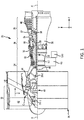
FIG. 1 illustrates a cross-section view of an exemplary gas turbine engine, in accordance with various embodiments; -
FIG. 2 illustrates a schematic of a fuel preservation system coupled to a fuel system of a gas turbine engine, in accordance with various embodiments; -
FIG. 3 illustrates a schematic of an input/output pin interface of an integrated fuel pump and control (IFPC), in accordance with various embodiments; -
FIGs. 4A and 4B illustrate schematics of a switch box of a fuel preservation system coupled to a metering valve of an IFPC, in accordance with various embodiments; and -
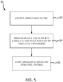
FIG. 5 illustrates a method of preserving a fuel system of a gas turbine engine, in accordance with various embodiments. - The detailed description of various embodiments herein makes reference to the accompanying drawings, which show various embodiments by way of illustration. While these various embodiments are described in sufficient detail to enable those skilled in the art to practice the disclosure, it should be understood that other embodiments may be realized and that logical, chemical, and mechanical changes may be made without departing from the scope of the disclosure. Thus, the detailed description herein is presented for purposes of illustration only and not of limitation. For example, the steps recited in any of the method or process descriptions may be executed in any order and are not necessarily limited to the order presented. Furthermore, any reference to singular includes plural embodiments, and any reference to more than one component or step may include a singular embodiment or step. Also, any reference to attached, fixed, connected, or the like may include permanent, removable, temporary, partial, full, and/or any other possible attachment option. Additionally, any reference to without contact (or similar phrases) may also include reduced contact or minimal contact.
- Cross hatching lines may be used throughout the figures to denote different parts but not necessarily to denote the same or different materials. Throughout the present disclosure, like reference numbers denote like elements. Accordingly, elements with like element numbering may be shown in the figures, but may not necessarily be repeated herein for the sake of clarity.
- With reference to
FIG. 1 , agas turbine engine 20 is shown according to various embodiments.Gas turbine engine 20 may be a two-spool turbofan that generally incorporates afan section 22, acompressor section 24, acombustor section 26 and aturbine section 28. Alternative engines may include, for example, an augmentor section among other systems or features. In operation,fan section 22 can drive coolant (e.g., air) along a path of bypass airflow B whilecompressor section 24 can drive coolant along a path of core airflow C for compression and communication intocombustor section 26 then expansion throughturbine section 28. Although depicted as a turbofangas turbine engine 20 herein, it should be understood that the concepts described herein are not limited to use with turbofans as the teachings may be applied to other types of turbine engines including three-spool architectures. -
Gas turbine engine 20 may generally comprise alow speed spool 30 and ahigh speed spool 32 mounted for rotation about an engine central longitudinal axis A-A' relative to an enginestatic structure 36 or engine case viaseveral bearing systems 38, 38-1, and 38-2. Engine central longitudinal axis A-A' is oriented in the z direction on the provided x-y-z axes. It should be understood that various bearingsystems 38 at various locations may alternatively or additionally be provided, including for example, bearingsystem 38, bearing system 38-1, and bearing system 38-2. -
Low speed spool 30 may generally comprise aninner shaft 40 that interconnects afan 42, alow pressure compressor 44 and alow pressure turbine 46.Inner shaft 40 may be connected to fan 42 through a gearedarchitecture 48 that can drivefan 42 at a lower speed thanlow speed spool 30.Geared architecture 48 may comprise agear assembly 60 enclosed within agear housing 62.Gear assembly 60 couplesinner shaft 40 to a rotating fan structure.High speed spool 32 may comprise anouter shaft 50 that interconnects ahigh pressure compressor 52 andhigh pressure turbine 54. Acombustor 56 may be located betweenhigh pressure compressor 52 andhigh pressure turbine 54. Amid-turbine frame 57 of enginestatic structure 36 may be located generally betweenhigh pressure turbine 54 andlow pressure turbine 46.Mid-turbine frame 57 may support one ormore bearing systems 38 inturbine section 28.Inner shaft 40 andouter shaft 50 may be concentric and rotate via bearingsystems 38 about the engine central longitudinal axis A-A', which is collinear with their longitudinal axes. As used herein, a "high pressure" compressor or turbine experiences a higher pressure than a corresponding "low pressure" compressor or turbine. - The core airflow C may be compressed by
low pressure compressor 44 thenhigh pressure compressor 52, mixed and burned with fuel incombustor 56, then expanded overhigh pressure turbine 54 andlow pressure turbine 46.Turbines low speed spool 30 andhigh speed spool 32 in response to the expansion. -
Gas turbine engine 20 may be, for example, a high-bypass ratio geared aircraft engine. In various embodiments, the bypass ratio ofgas turbine engine 20 may be greater than about six (6). In various embodiments, the bypass ratio ofgas turbine engine 20 may be greater than ten (10). In various embodiments, gearedarchitecture 48 may be an epicyclic gear train, such as a star gear system (sun gear in meshing engagement with a plurality of star gears supported by a carrier and in meshing engagement with a ring gear) or other gear system.Geared architecture 48 may have a gear reduction ratio of greater than about 2.3 andlow pressure turbine 46 may have a pressure ratio that is greater than about five (5). In various embodiments, the bypass ratio ofgas turbine engine 20 is greater than about ten (10:1). In various embodiments, the diameter offan 42 may be significantly larger than that of thelow pressure compressor 44, and thelow pressure turbine 46 may have a pressure ratio that is greater than about five (5:1).Low pressure turbine 46 pressure ratio may be measured prior to inlet oflow pressure turbine 46 as related to the pressure at the outlet oflow pressure turbine 46 prior to an exhaust nozzle. It should be understood, however, that the above parameters are exemplary of various embodiments of a suitable geared architecture engine and that the present disclosure contemplates other gas turbine engines including direct drive turbofans. A gas turbine engine may comprise an industrial gas turbine (IGT) or a geared aircraft engine, such as a geared turbofan, or non-geared aircraft engine, such as a turbofan, or may comprise any gas turbine engine as desired. - An
accessory gearbox 90 may be mechanically coupled togas turbine engine 20. In various embodiments,accessory gearbox 90 may be mechanically coupled toouter shaft 50 via atower shaft 92.Accessory gearbox 90 may extract power fromgas turbine engine 20 in order to drive one or more accessories ofgas turbine engine 20 and/or of the aircraft to whichgas turbine engine 20 may be mounted. For example,gas turbine engine 20 may comprise one or more interfaces for transferring power extracted fromouter shaft 50 to one or more component of, for example, afuel system 100 ofgas turbine engine 20. - With reference to
FIG. 2 , a schematic illustration offuel system 100 in combination with a portablefuel preservation system 200 for injecting preservation fluid intofuel system 100 is shown, in accordance with various embodiments.Fuel system 100 may comprise an integrated fuel pump and control (IFPC) 102, afuel manifold 104, anactuator 106, afuel supply manifold 108,fuel nozzles 110, a fuel/oil heat exchanger 112, and afuel filter 114. The components offuel system 100 may be fluidly coupled to one another viacold fuel conduits 116 andwarm fuel conduits IFPC 102 to fuel/oil heat exchanger 112 viafuel supply manifold 108 andcold fuel conduits 116. Fuel/oil heat exchanger 112 may warm the cold fuel received fromfuel supply manifold 108, and the warmed fuel may be returned toIFPC 102 viafuel supply manifold 108,fuel filter 114, andwarm fuel conduits 118.IFPC 102 may then distribute the warmed fuel to the other components of fuel system 100 (e.g.,actuator 106,fuel nozzles 110, etc.) viawarm fuel conduits 120. -
IFPC 102 may be configured to regulate the volume of fluid (e.g., the cool and/or warm fuel) dispensed to the other components offuel system 100. In that regard,IFPC 102 may comprise one or more valves for controlling the flow of fluid to and from the components offuel system 100. In various embodiments,IFPC 102 may comprise afuel metering valve 130, anoverspeed solenoid valve 132, and a pressureequalization solenoid valve 134. The opening and closing offuel metering valve 130,overspeed solenoid valve 132, and pressureequalization solenoid valve 134 may regulate the flow of liquid throughfuel system 100. - An electronic engine controller (EEC) 140 may be electrically coupled to
IFPC 102 via communication channels (e.g., wires or cables) 142.EEC 140 may be configured to make decisions regarding the control and operation ofengine 20.EEC 140 may be part of a Full Authority Digital Engine Control (FADEC).EEC 140 may comprise one or more processors configured to implement various logical operations in response to execution of instructions, for example, instructions stored on a non-transitory, tangible, computer-readable medium. The one or more processors can be a general purpose processor, a microprocessor, a microcontroller, a digital signal processor (DSP), an application specific integrated circuit (ASIC), a field programmable gate array (FPGA) or other programmable logic device, discrete gate or transistor logic, discrete hardware components, or any combination thereof. -
EEC 140 may comprise system program instructions and/or controller instructions that may be loaded onto a non-transitory, tangible computer-readable medium having instructions stored thereon that, in response to execution by a controller, cause the controller to perform various operations. The term "non-transitory" is to be understood to remove only propagating transitory signals per se from the claim scope and does not relinquish rights to all standard computer-readable media that are not only propagating transitory signals per se. Stated another way, the meaning of the term "non-transitory computer-readable medium" and "non-transitory computer-readable storage medium" should be construed to exclude only those types of transitory computer-readable media which were found in In Re Nuijten to fall outside the scope of patentable subject matter under 35 U.S.C. § 101. -
EEC 140 may be configured to provide optimum engine efficiency by controlling aspects of operation offuel system 100. In various embodiments,EEC 140 may be in operable communication withIFPC 102. For example,EEC 140 may receive fuel temperature data output from one or more resistance temperature detector(s) (RTD) 136 withinIFPC 102.EEC 140 may receive data related to the position ofmetering valve 130 from one or more linear variable differential transformer(s) (LVDT) 138 withinIFPC 102. EEC may output commands toIFPC 102, for example, commands relating to the opening and closing ofvalves IFPC 102 and/or in response to other engine operating data. In that regard,metering valve 130 andsolenoid valves fuel system 100 receive fluid and the volume of fluid received. - During preservation of
fuel system 100, it may be desirable for all valves ofIFPC 102 to be opened such that preservation fluid may flow to and cover various components offuel system 100 that are in need of preservation. In that regard, aswitch box 202 of portablefuel preservation system 200 may be coupled to a first input/output pin interface 302a ofIFPC 102 to generate an actuation ofmetering valve 130. The actuation ofmetering valve 130 byswitch box 202 may also causesolenoid valves metering valve 130 andsolenoid valves fuel system 100. In various embodiments,switch box 202 of portablefuel preservation system 200 may cause valves inIFPC 102 and in various components throughoutfuel system 100 that would not be opened together during engine operating conditions to open. Opening valves which are not normally opened at the same time may allow for preservation fluid to flow more freely and quickly throughfuel system 100. - With reference to
FIG. 3 , a schematic illustration of the input/output pins ofIFPC 102 is shown, in accordance with various embodiments. Afirst pin interface 302a ofIFPC 102 may comprise pins that convey electrical signals into or out ofIFPC 102. In various embodiments,IFPC 102 may comprise a first fifteen pin input/output interface 302a, and a second fifteen pin input/output interface 302b. The pin configuration of second input/output pin interface 302b may be identical to the pin configuration offirst pin interface 302a, such thatsecond pin interface 302b may provide a redundancy. In that regard, switch box 202 (FIG. 2 ) may be compatible with bothfirst pin interface 302a andsecond pin interface 302b. Stated another way,switch box 202 may be coupled to eitherfirst pin interface 302a orsecond pin interface 302b to actuatemetering valve 130. - In various embodiments, pins 9a and 10a of
first pin interface 302a and pins 9b and 10b ofsecond pin interface 302b may be electrically coupled toRTD 136 ofIFPC 102.Pins first pin interface 302a and pins 13b and 12b ofsecond pin interface 302b may be electrically coupled tooverspeed solenoid valve 132 ofIFPC 102.Pins first pin interface 302a and pins 15b and 4b ofsecond pin interface 302b may be electrically coupled tometering valve 130 ofIFPC 102.Pins first pin interface 302a and pins 5b, 6b, 7b, 8b, and 1b ofsecond pin interface 302b may be electrically coupled toLVDT 138 ofIFPC 102.Pins first pin interface 302a and pins 2b and 11b ofsecond pin interface 302b may be electrically coupled to pressureequalization solenoid valve 134 ofIFPC 102.Pins first pin interface 302a and pins 3b and 14b ofsecond pin interface 302b may be extra pins which are not electrically coupled to any components ofIFPC 102. - With combined reference to
FIG. 2 andFIG. 4A , during preservation offuel system 100, amating connector 330 electrically coupled to switchbox 202 may engagefirst pin interface 302a ofIFPC 102.Mating connector 330 may be electrically coupled to acircuit 310 ofswitch box 202 via a wire orcable 332.Mating connector 330 may include 15 pins configured to engage the 15 pins offirst pin interface 302a orsecond pin interface 302b. In that regard,switch box 202 may be electrically coupled toIFPC 102 by connectingmating connector 330 tofirst pin interface 302a orsecond pin interface 302b. In various embodiments, only the pins engaged withpins switch box 202. For example, pin 315 and pin 304 ofmating connector 330 may engage to pin 15a andpin 4a, respectively, offirst pin interface 302a, and may be electrically coupled tocircuit 310. - With reference to
FIG. 4A ,circuit 310 may comprise apower supply 312, aswitch 316, anindicator light 322, and aresistor 314.Switch 316 may be configured to open andclose circuit 310.Resistor 314 may be coupled between the positive power supply terminal ofpower supply 312 andpin 315.Pin 304 may be coupled to the negative power supply terminal ofpower supply 312.Circuit 310 may generate a current configured to open themetering valve 130. In various embodiments,circuit 310 may generate a current between 10 milliamp and 50 milliamp. In various embodiments,circuit 310 may generate a current between 20 milliamp and 30 milliamp. For example, in various embodiments,resistor 314 may comprise a one kilo-ohm resistor andpower supply 312 may comprise a 28 volt power supply. - With combined reference to
FIG. 2 andFIG. 4A ,switch box 202 may comprise amechanical switch 320 coupled to switch 316 and configured to open andclose circuit 310. In various embodiments,resistor 314 may comprise a potentiometer, andmechanical switch 320 may comprise a knob configured to vary the resistance ofresistor 314. In various embodiments,switch box 202 may comprise theindicator light 322.Indicator light 322 may be configured to illuminate whencircuit 310 is either open or closed. In various embodiments,indicator light 322 may provide visual indication to the user that theswitch box 202 is turned on (i.e., thatcircuit 310 is closed andswitch box 202 is generating a current) or thatswitch box 202 is turned off (i.e., thatcircuit 310 is open andswitch box 202 is not generating a current). In various embodiments,indicator light 322 may comprise a light-emitting diode (LED). Switch box may be configured to be powered by an external power source (e.g., via a 120V 60Hz AC supply) or by a battery included within switch box. - With reference to
FIG. 4B , in various embodiments,switch box 202 may comprise acircuit 350.Circuit 350 may comprise apower supply 352, aswitch 356, and anindicator light 362.Switch 356 may be configured to open andclose circuit 350. The positive power supply terminal ofpower supply 352 may be coupled topins Pins power supply 352.Circuit 350 may supply a voltage tometering valve 130. The voltage supplied bycircuit 350 may cause an actuation ofmetering valve 130. Stated another way, in various embodiments,metering valve 130 may be configured such that a voltage, as opposed to a current, will causemetering valve 130 to open and close. In various embodiments, with combined reference toFIG. 4B andFIG. 3 , the voltage supplied bycircuit 350 may causemetering valve 130 andsolenoid valves FIG. 2 ). - Returning to
FIG. 2 ,portable preservation system 200 may include acart 204.Cart 204 may be portable such thatcart 204 may be taken to an engine that has been removed from an aircraft.Switch box 202 may be coupled tocart 204.Cart 204 may include adriver 206 for injecting preservation fluid intofuel system 100. For example,driver 206 may inject the preservation fluid into aninlet 154 ofIFPC 102 viaconduit 156.Cart 204 includingswitch box 202 anddriver 206 may formportable preservation system 200 which may be taken to engine 20 (FIG. 1 ). For example, the use ofportable preservation system 200 may permit fuel system preservation to be conducted after removingengine 20 from an aircraft and without employing an engine test cell. In that regard, preservation may be conducted without supplying electrical power to be supplied toEEC 140 and/or without operatinggas turbine engine 20. In various embodiments,switch box 202 andEEC 140 may both be coupled toIFPC 102 thoughonly switch box 202 receives power and supplies voltage and/or current toIFPC 102. The current generated byswitch box 202 ofportable preservation system 200 may create a magnetic field that actuates the torque motor ofmetering valve 130, which may actuatesolenoid valves switch box 202 may causemetering valve 130 andsolenoid valves driver 206 to flow throughfuel system 100. - With reference to
FIG. 5 , amethod 500 of preserving a fuel system of a gas turbine engine is disclosed, in accordance with various embodiments.Method 500 may comprise coupling a switch box of a portable fuel preservation system to an integrated fuel pump and control of the gas turbine engine (step 502), opening a metering valve of the integrated fuel pump and control using a current generated by closing a circuit of the switch box (step 504), and injecting a preservation fluid into the fuel system (step 506). In various embodiments, coupling the switch box to the integrated fuel pump and control may comprise engaging a mating connector coupled to the switch box with a pin interface of the integrated fuel pump and control, and wherein a first pin of the mating connector is electrically coupled to the circuit. The circuit may comprise a power supply electrically coupled to the first pin of the mating connector. The first pin of the mating connector may be configured to engage a second pin of the pin interface. The second pin may be electrically connected to the metering valve of the integrated fuel pump. A resistor may be coupled between the power supply and the first pin. The resistor may comprise a one kilo-ohm resistor. The current generated by closing the circuit of the switch box may be between 10 milliamp and 50 milliamp. Opening the metering valve may cause a first solenoid valve and a second solenoid valve of the integrated fuel pump and control to open. - Benefits, other advantages, and solutions to problems have been described herein with regard to specific embodiments. Furthermore, the connecting lines shown in the various figures contained herein are intended to represent exemplary functional relationships and/or physical couplings between the various elements. It should be noted that many alternative or additional functional relationships or physical connections may be present in a practical system. However, the benefits, advantages, solutions to problems, and any elements that may cause any benefit, advantage, or solution to occur or become more pronounced are not to be construed as critical, required, or essential features or elements of the inventions. The scope of the inventions is accordingly to be limited by nothing other than the appended claims, in which reference to an element in the singular is not intended to mean "one and only one" unless explicitly so stated, but rather "one or more." Moreover, where a phrase similar to "at least one of A, B, or C" is used in the claims, it is intended that the phrase be interpreted to mean that A alone may be present in an embodiment, B alone may be present in an embodiment, C alone may be present in an embodiment, or that any combination of the elements A, B and C may be present in a single embodiment; for example, A and B, A and C, B and C, or A and B and C.
- Systems, methods and apparatus are provided herein. In the detailed description herein, references to "one embodiment," "an embodiment," "various embodiments," etc., indicate that the embodiment described may include a particular feature, structure, or characteristic, but every embodiment may not necessarily include the particular feature, structure, or characteristic. Moreover, such phrases are not necessarily referring to the same embodiment. Further, when a particular feature, structure, or characteristic is described in connection with an embodiment, it is submitted that it may be within the knowledge of one skilled in the art to affect such feature, structure, or characteristic in connection with other embodiments whether or not explicitly described. After reading the description, it will be apparent to one skilled in the relevant art(s) how to implement the disclosure in alternative embodiments.
- Furthermore, no element, component, or method step in the present disclosure is intended to be dedicated to the public regardless of whether the element, component, or method step is explicitly recited in the claims. No claim element herein is to be construed under the provisions of 35 U.S.C. 112(f) unless the element is expressly recited using the phrase "means for." As used herein, the terms "comprises," "comprising," or any other variation thereof, are intended to cover a non-exclusive inclusion, such that a process, method, article, or apparatus that comprises a list of elements does not include only those elements but may include other elements not expressly listed or inherent to such process, method, article, or apparatus.
Claims (15)
- A switch box for a portable fuel preservation system, comprising:a mating connector configured to engage a pin interface of an integrated fuel pump and control; anda circuit electrically coupled to the mating connector, the circuit comprising:a power supply electrically coupled to a first pin of the mating connector, wherein the first pin of the mating connector is configured to engage a second pin of the pin interface, and wherein the second pin is electrically connected to a metering valve of the integrated fuel pump; anda resistor coupled between the power supply and the first pin.
- The switch box of claim 1, wherein the power supply comprises a 28 volt power supply.
- The switch box of claim 1 or 2, further comprising a mechanical switch configured to open and close the circuit.
- The switch box of claim 1, 2 or 3, wherein the power supply and the resistor generate between a 10 milliamp and 50 milliamp current.
- The switch box of any preceding claim, wherein the resistor comprises a potentiometer.
- A portable fuel preservation system, comprising:a switch box configured to be coupled to an integrated fuel pump and control of a gas turbine engine, and cause a metering valve of the integrated fuel pump and control and a solenoid valve of the integrated fuel pump and control to open and close; anda driver configured to inject preservation fluid into the integrated fuel pump and control.
- The portable fuel preservation system of claim 6, wherein the switch box comprises:a mating connector configured to engage a pin interface of the integrated fuel pump and control; anda circuit electrically coupled to the mating connector, the circuit comprising a power supply electrically coupled to a first pin of the mating connector, wherein the first pin of the mating connector is configured to engage a second pin of the pin interface, and wherein the second pin is electrically connected to the metering valve of the integrated fuel pump.
- The portable fuel preservation system of claim 7, wherein the circuit further comprises a resistor coupled between the power supply and the first pin.
- The portable fuel preservation system of claim 8, wherein the circuit generates a current between 10 milliamp and 50 milliamp to open the metering valve of the integrated fuel pump.
- The portable fuel preservation system of any of claims 7 to 9, wherein the circuit supplies a voltage configured to actuate the metering valve.
- The switch box of any of claims 3 to 5, or the portable fuel preservation system of any of claims 6 to 10, wherein the switch box further comprises an indicator light configured to illuminate when the circuit is at least one of open or closed.
- A method of preserving a fuel system of a gas turbine engine, comprising:coupling a switch box of a portable fuel preservation system to an integrated fuel pump and control of the gas turbine engine;opening a metering valve of the integrated fuel pump and control using a current generated by closing a circuit of the switch box; andinjecting a preservation fluid into the fuel system.
- The method of claim 12, wherein the coupling the switch box to the integrated fuel pump and control comprises engaging a mating connector coupled to the switch box with a pin interface of the integrated fuel pump and control, and wherein a first pin of the mating connector is electrically coupled to the circuit, and/or
wherein, optionally, the current generated by closing the circuit of the switch box is between 10 milliamp and 50 milliamp, and/or
wherein, optionally, the opening the metering valve causes a first solenoid valve and a second solenoid valve of the integrated fuel pump and control to open. - The method of claim 13, wherein the circuit comprises:a power supply electrically coupled to the first pin of the mating connector, wherein the first pin of the mating connector is configured to engage a second pin of the pin interface, and wherein the second pin is electrically connected to the metering valve of the integrated fuel pump; anda resistor coupled between the power supply and the first pin.
- The switch box of any of claims 1 to 5 or 11, the portable fuel preservation system of any of claims 8 to 11, or the method of claim 14, wherein the resistor comprises a one kilo-ohm resistor.
Applications Claiming Priority (1)
| Application Number | Priority Date | Filing Date | Title |
|---|---|---|---|
| US15/694,358 US11053863B2 (en) | 2017-09-01 | 2017-09-01 | Integrated fuel pump and control preservation system |
Publications (2)
| Publication Number | Publication Date |
|---|---|
| EP3450725A1 true EP3450725A1 (en) | 2019-03-06 |
| EP3450725B1 EP3450725B1 (en) | 2022-03-30 |
Family
ID=63637631
Family Applications (1)
| Application Number | Title | Priority Date | Filing Date |
|---|---|---|---|
| EP18191482.1A Active EP3450725B1 (en) | 2017-09-01 | 2018-08-29 | Integrated fuel pump and control preservation system |
Country Status (2)
| Country | Link |
|---|---|
| US (1) | US11053863B2 (en) |
| EP (1) | EP3450725B1 (en) |
Cited By (1)
| Publication number | Priority date | Publication date | Assignee | Title |
|---|---|---|---|---|
| EP4116559A1 (en) * | 2021-07-09 | 2023-01-11 | Raytheon Technologies Corporation | De-preserving a fuel system of a turbine engine |
Families Citing this family (1)
| Publication number | Priority date | Publication date | Assignee | Title |
|---|---|---|---|---|
| GB201914887D0 (en) * | 2019-10-15 | 2019-11-27 | Rolls Royce Plc | Electronic engine controller |
Citations (4)
| Publication number | Priority date | Publication date | Assignee | Title |
|---|---|---|---|---|
| SU830720A1 (en) * | 1980-01-03 | 1996-01-27 | В.В. Белоусов | Method of internal conservation of aircraft gas-turbine engine fuel system |
| IL198606A (en) * | 2006-11-07 | 2012-04-30 | Zakrytoe Aktsionernoe Obschestvo Vao Interprofavia | Method and device for internal preservation and/or depreservation of gas-turbine engines |
| US20130032215A1 (en) * | 2010-04-12 | 2013-02-07 | Mtu Aero Engines Gmbh | Device and method for preserving fluid systems and an engine |
| US20160349762A1 (en) * | 2015-05-29 | 2016-12-01 | Pratt & Whitney Canada Corp. | Method and kit for preserving a fuel system of an aircraft engine |
Family Cites Families (6)
| Publication number | Priority date | Publication date | Assignee | Title |
|---|---|---|---|---|
| US3591962A (en) * | 1969-03-26 | 1971-07-13 | Systems Capital Corp | Cryogenic power source for starting jet engines |
| US4041696A (en) * | 1976-05-24 | 1977-08-16 | General Motors Corporation | Vehicle turbine manual control |
| US4697238A (en) * | 1981-01-21 | 1987-09-29 | Teledyne Industries, Inc. | Integrated fuel management system |
| US6882924B2 (en) * | 2003-05-05 | 2005-04-19 | Precision Engine Controls Corp. | Valve flow control system and method |
| US7237535B2 (en) * | 2005-04-11 | 2007-07-03 | Honeywell International Inc. | Enhanced accuracy fuel metering system and method |
| US9739168B2 (en) * | 2014-06-05 | 2017-08-22 | General Electric Company | Off-line wash systems and methods for a gas turbine engine |
-
2017
- 2017-09-01 US US15/694,358 patent/US11053863B2/en active Active
-
2018
- 2018-08-29 EP EP18191482.1A patent/EP3450725B1/en active Active
Patent Citations (4)
| Publication number | Priority date | Publication date | Assignee | Title |
|---|---|---|---|---|
| SU830720A1 (en) * | 1980-01-03 | 1996-01-27 | В.В. Белоусов | Method of internal conservation of aircraft gas-turbine engine fuel system |
| IL198606A (en) * | 2006-11-07 | 2012-04-30 | Zakrytoe Aktsionernoe Obschestvo Vao Interprofavia | Method and device for internal preservation and/or depreservation of gas-turbine engines |
| US20130032215A1 (en) * | 2010-04-12 | 2013-02-07 | Mtu Aero Engines Gmbh | Device and method for preserving fluid systems and an engine |
| US20160349762A1 (en) * | 2015-05-29 | 2016-12-01 | Pratt & Whitney Canada Corp. | Method and kit for preserving a fuel system of an aircraft engine |
Cited By (2)
| Publication number | Priority date | Publication date | Assignee | Title |
|---|---|---|---|---|
| EP4116559A1 (en) * | 2021-07-09 | 2023-01-11 | Raytheon Technologies Corporation | De-preserving a fuel system of a turbine engine |
| EP4589128A3 (en) * | 2021-07-09 | 2025-10-29 | RTX Corporation | De-preserving a fuel system of a turbine engine |
Also Published As
| Publication number | Publication date |
|---|---|
| US11053863B2 (en) | 2021-07-06 |
| US20190072041A1 (en) | 2019-03-07 |
| EP3450725B1 (en) | 2022-03-30 |
Similar Documents
| Publication | Publication Date | Title |
|---|---|---|
| EP3845747B1 (en) | Systems and methods for fuel cell auxiliary power in secondary fuel applications | |
| US12345204B2 (en) | Methods for power transfer in cryogenic fuel applications | |
| EP3514335B1 (en) | Systems and methods of low spool power extraction | |
| US12044149B2 (en) | Cooling system for power cables in a gas turbine engine | |
| US11815029B2 (en) | Power assisted engine start bleed system | |
| US10443622B2 (en) | Active core cooling system | |
| US10107157B2 (en) | Gas turbine engine lubrication system | |
| US11248523B2 (en) | Dual clutch transmission for accessory gearbox drive | |
| EP3483412A1 (en) | Gas turbine engine with mid-compressor bleed | |
| EP3450725B1 (en) | Integrated fuel pump and control preservation system | |
| US10808627B2 (en) | Double bore basket | |
| US10294870B2 (en) | Distributed engine accessory drive | |
| US10294823B2 (en) | Dirt evacuation devices | |
| EP3315759A1 (en) | Electric heating for fuel system components | |
| US20200284166A1 (en) | Cover secured by captive fastener | |
| EP3249176A1 (en) | Dirt shield |
Legal Events
| Date | Code | Title | Description |
|---|---|---|---|
| PUAI | Public reference made under article 153(3) epc to a published international application that has entered the european phase |
Free format text: ORIGINAL CODE: 0009012 |
|
| STAA | Information on the status of an ep patent application or granted ep patent |
Free format text: STATUS: THE APPLICATION HAS BEEN PUBLISHED |
|
| AK | Designated contracting states |
Kind code of ref document: A1 Designated state(s): AL AT BE BG CH CY CZ DE DK EE ES FI FR GB GR HR HU IE IS IT LI LT LU LV MC MK MT NL NO PL PT RO RS SE SI SK SM TR |
|
| AX | Request for extension of the european patent |
Extension state: BA ME |
|
| STAA | Information on the status of an ep patent application or granted ep patent |
Free format text: STATUS: REQUEST FOR EXAMINATION WAS MADE |
|
| 17P | Request for examination filed |
Effective date: 20190906 |
|
| RBV | Designated contracting states (corrected) |
Designated state(s): AL AT BE BG CH CY CZ DE DK EE ES FI FR GB GR HR HU IE IS IT LI LT LU LV MC MK MT NL NO PL PT RO RS SE SI SK SM TR |
|
| STAA | Information on the status of an ep patent application or granted ep patent |
Free format text: STATUS: EXAMINATION IS IN PROGRESS |
|
| 17Q | First examination report despatched |
Effective date: 20201109 |
|
| RAP1 | Party data changed (applicant data changed or rights of an application transferred) |
Owner name: RAYTHEON TECHNOLOGIES CORPORATION |
|
| GRAP | Despatch of communication of intention to grant a patent |
Free format text: ORIGINAL CODE: EPIDOSNIGR1 |
|
| STAA | Information on the status of an ep patent application or granted ep patent |
Free format text: STATUS: GRANT OF PATENT IS INTENDED |
|
| INTG | Intention to grant announced |
Effective date: 20211022 |
|
| GRAS | Grant fee paid |
Free format text: ORIGINAL CODE: EPIDOSNIGR3 |
|
| GRAA | (expected) grant |
Free format text: ORIGINAL CODE: 0009210 |
|
| STAA | Information on the status of an ep patent application or granted ep patent |
Free format text: STATUS: THE PATENT HAS BEEN GRANTED |
|
| AK | Designated contracting states |
Kind code of ref document: B1 Designated state(s): AL AT BE BG CH CY CZ DE DK EE ES FI FR GB GR HR HU IE IS IT LI LT LU LV MC MK MT NL NO PL PT RO RS SE SI SK SM TR |
|
| REG | Reference to a national code |
Ref country code: GB Ref legal event code: FG4D |
|
| REG | Reference to a national code |
Ref country code: CH Ref legal event code: EP |
|
| REG | Reference to a national code |
Ref country code: AT Ref legal event code: REF Ref document number: 1479399 Country of ref document: AT Kind code of ref document: T Effective date: 20220415 |
|
| REG | Reference to a national code |
Ref country code: DE Ref legal event code: R096 Ref document number: 602018032865 Country of ref document: DE |
|
| REG | Reference to a national code |
Ref country code: IE Ref legal event code: FG4D |
|
| REG | Reference to a national code |
Ref country code: LT Ref legal event code: MG9D |
|
| PG25 | Lapsed in a contracting state [announced via postgrant information from national office to epo] |
Ref country code: SE Free format text: LAPSE BECAUSE OF FAILURE TO SUBMIT A TRANSLATION OF THE DESCRIPTION OR TO PAY THE FEE WITHIN THE PRESCRIBED TIME-LIMIT Effective date: 20220330 Ref country code: RS Free format text: LAPSE BECAUSE OF FAILURE TO SUBMIT A TRANSLATION OF THE DESCRIPTION OR TO PAY THE FEE WITHIN THE PRESCRIBED TIME-LIMIT Effective date: 20220330 Ref country code: NO Free format text: LAPSE BECAUSE OF FAILURE TO SUBMIT A TRANSLATION OF THE DESCRIPTION OR TO PAY THE FEE WITHIN THE PRESCRIBED TIME-LIMIT Effective date: 20220630 Ref country code: LT Free format text: LAPSE BECAUSE OF FAILURE TO SUBMIT A TRANSLATION OF THE DESCRIPTION OR TO PAY THE FEE WITHIN THE PRESCRIBED TIME-LIMIT Effective date: 20220330 Ref country code: HR Free format text: LAPSE BECAUSE OF FAILURE TO SUBMIT A TRANSLATION OF THE DESCRIPTION OR TO PAY THE FEE WITHIN THE PRESCRIBED TIME-LIMIT Effective date: 20220330 Ref country code: BG Free format text: LAPSE BECAUSE OF FAILURE TO SUBMIT A TRANSLATION OF THE DESCRIPTION OR TO PAY THE FEE WITHIN THE PRESCRIBED TIME-LIMIT Effective date: 20220630 |
|
| REG | Reference to a national code |
Ref country code: NL Ref legal event code: MP Effective date: 20220330 |
|
| REG | Reference to a national code |
Ref country code: AT Ref legal event code: MK05 Ref document number: 1479399 Country of ref document: AT Kind code of ref document: T Effective date: 20220330 |
|
| PG25 | Lapsed in a contracting state [announced via postgrant information from national office to epo] |
Ref country code: LV Free format text: LAPSE BECAUSE OF FAILURE TO SUBMIT A TRANSLATION OF THE DESCRIPTION OR TO PAY THE FEE WITHIN THE PRESCRIBED TIME-LIMIT Effective date: 20220330 Ref country code: GR Free format text: LAPSE BECAUSE OF FAILURE TO SUBMIT A TRANSLATION OF THE DESCRIPTION OR TO PAY THE FEE WITHIN THE PRESCRIBED TIME-LIMIT Effective date: 20220701 Ref country code: FI Free format text: LAPSE BECAUSE OF FAILURE TO SUBMIT A TRANSLATION OF THE DESCRIPTION OR TO PAY THE FEE WITHIN THE PRESCRIBED TIME-LIMIT Effective date: 20220330 |
|
| PG25 | Lapsed in a contracting state [announced via postgrant information from national office to epo] |
Ref country code: NL Free format text: LAPSE BECAUSE OF FAILURE TO SUBMIT A TRANSLATION OF THE DESCRIPTION OR TO PAY THE FEE WITHIN THE PRESCRIBED TIME-LIMIT Effective date: 20220330 |
|
| PG25 | Lapsed in a contracting state [announced via postgrant information from national office to epo] |
Ref country code: SM Free format text: LAPSE BECAUSE OF FAILURE TO SUBMIT A TRANSLATION OF THE DESCRIPTION OR TO PAY THE FEE WITHIN THE PRESCRIBED TIME-LIMIT Effective date: 20220330 Ref country code: SK Free format text: LAPSE BECAUSE OF FAILURE TO SUBMIT A TRANSLATION OF THE DESCRIPTION OR TO PAY THE FEE WITHIN THE PRESCRIBED TIME-LIMIT Effective date: 20220330 Ref country code: RO Free format text: LAPSE BECAUSE OF FAILURE TO SUBMIT A TRANSLATION OF THE DESCRIPTION OR TO PAY THE FEE WITHIN THE PRESCRIBED TIME-LIMIT Effective date: 20220330 Ref country code: PT Free format text: LAPSE BECAUSE OF FAILURE TO SUBMIT A TRANSLATION OF THE DESCRIPTION OR TO PAY THE FEE WITHIN THE PRESCRIBED TIME-LIMIT Effective date: 20220801 Ref country code: ES Free format text: LAPSE BECAUSE OF FAILURE TO SUBMIT A TRANSLATION OF THE DESCRIPTION OR TO PAY THE FEE WITHIN THE PRESCRIBED TIME-LIMIT Effective date: 20220330 Ref country code: EE Free format text: LAPSE BECAUSE OF FAILURE TO SUBMIT A TRANSLATION OF THE DESCRIPTION OR TO PAY THE FEE WITHIN THE PRESCRIBED TIME-LIMIT Effective date: 20220330 Ref country code: CZ Free format text: LAPSE BECAUSE OF FAILURE TO SUBMIT A TRANSLATION OF THE DESCRIPTION OR TO PAY THE FEE WITHIN THE PRESCRIBED TIME-LIMIT Effective date: 20220330 Ref country code: AT Free format text: LAPSE BECAUSE OF FAILURE TO SUBMIT A TRANSLATION OF THE DESCRIPTION OR TO PAY THE FEE WITHIN THE PRESCRIBED TIME-LIMIT Effective date: 20220330 |
|
| PG25 | Lapsed in a contracting state [announced via postgrant information from national office to epo] |
Ref country code: PL Free format text: LAPSE BECAUSE OF FAILURE TO SUBMIT A TRANSLATION OF THE DESCRIPTION OR TO PAY THE FEE WITHIN THE PRESCRIBED TIME-LIMIT Effective date: 20220330 Ref country code: IS Free format text: LAPSE BECAUSE OF FAILURE TO SUBMIT A TRANSLATION OF THE DESCRIPTION OR TO PAY THE FEE WITHIN THE PRESCRIBED TIME-LIMIT Effective date: 20220730 Ref country code: AL Free format text: LAPSE BECAUSE OF FAILURE TO SUBMIT A TRANSLATION OF THE DESCRIPTION OR TO PAY THE FEE WITHIN THE PRESCRIBED TIME-LIMIT Effective date: 20220330 |
|
| REG | Reference to a national code |
Ref country code: DE Ref legal event code: R097 Ref document number: 602018032865 Country of ref document: DE |
|
| PG25 | Lapsed in a contracting state [announced via postgrant information from national office to epo] |
Ref country code: DK Free format text: LAPSE BECAUSE OF FAILURE TO SUBMIT A TRANSLATION OF THE DESCRIPTION OR TO PAY THE FEE WITHIN THE PRESCRIBED TIME-LIMIT Effective date: 20220330 |
|
| PLBE | No opposition filed within time limit |
Free format text: ORIGINAL CODE: 0009261 |
|
| STAA | Information on the status of an ep patent application or granted ep patent |
Free format text: STATUS: NO OPPOSITION FILED WITHIN TIME LIMIT |
|
| 26N | No opposition filed |
Effective date: 20230103 |
|
| PG25 | Lapsed in a contracting state [announced via postgrant information from national office to epo] |
Ref country code: MC Free format text: LAPSE BECAUSE OF FAILURE TO SUBMIT A TRANSLATION OF THE DESCRIPTION OR TO PAY THE FEE WITHIN THE PRESCRIBED TIME-LIMIT Effective date: 20220330 |
|
| REG | Reference to a national code |
Ref country code: CH Ref legal event code: PL |
|
| PG25 | Lapsed in a contracting state [announced via postgrant information from national office to epo] |
Ref country code: LU Free format text: LAPSE BECAUSE OF NON-PAYMENT OF DUE FEES Effective date: 20220829 Ref country code: LI Free format text: LAPSE BECAUSE OF NON-PAYMENT OF DUE FEES Effective date: 20220831 Ref country code: CH Free format text: LAPSE BECAUSE OF NON-PAYMENT OF DUE FEES Effective date: 20220831 |
|
| REG | Reference to a national code |
Ref country code: BE Ref legal event code: MM Effective date: 20220831 |
|
| PG25 | Lapsed in a contracting state [announced via postgrant information from national office to epo] |
Ref country code: SI Free format text: LAPSE BECAUSE OF FAILURE TO SUBMIT A TRANSLATION OF THE DESCRIPTION OR TO PAY THE FEE WITHIN THE PRESCRIBED TIME-LIMIT Effective date: 20220330 |
|
| P01 | Opt-out of the competence of the unified patent court (upc) registered |
Effective date: 20230521 |
|
| PG25 | Lapsed in a contracting state [announced via postgrant information from national office to epo] |
Ref country code: IT Free format text: LAPSE BECAUSE OF FAILURE TO SUBMIT A TRANSLATION OF THE DESCRIPTION OR TO PAY THE FEE WITHIN THE PRESCRIBED TIME-LIMIT Effective date: 20220330 Ref country code: IE Free format text: LAPSE BECAUSE OF NON-PAYMENT OF DUE FEES Effective date: 20220829 |
|
| PG25 | Lapsed in a contracting state [announced via postgrant information from national office to epo] |
Ref country code: BE Free format text: LAPSE BECAUSE OF NON-PAYMENT OF DUE FEES Effective date: 20220831 |
|
| PG25 | Lapsed in a contracting state [announced via postgrant information from national office to epo] |
Ref country code: HU Free format text: LAPSE BECAUSE OF FAILURE TO SUBMIT A TRANSLATION OF THE DESCRIPTION OR TO PAY THE FEE WITHIN THE PRESCRIBED TIME-LIMIT; INVALID AB INITIO Effective date: 20180829 |
|
| PG25 | Lapsed in a contracting state [announced via postgrant information from national office to epo] |
Ref country code: CY Free format text: LAPSE BECAUSE OF FAILURE TO SUBMIT A TRANSLATION OF THE DESCRIPTION OR TO PAY THE FEE WITHIN THE PRESCRIBED TIME-LIMIT Effective date: 20220330 |
|
| PG25 | Lapsed in a contracting state [announced via postgrant information from national office to epo] |
Ref country code: MK Free format text: LAPSE BECAUSE OF FAILURE TO SUBMIT A TRANSLATION OF THE DESCRIPTION OR TO PAY THE FEE WITHIN THE PRESCRIBED TIME-LIMIT Effective date: 20220330 |
|
| PG25 | Lapsed in a contracting state [announced via postgrant information from national office to epo] |
Ref country code: TR Free format text: LAPSE BECAUSE OF FAILURE TO SUBMIT A TRANSLATION OF THE DESCRIPTION OR TO PAY THE FEE WITHIN THE PRESCRIBED TIME-LIMIT Effective date: 20220330 |
|
| PG25 | Lapsed in a contracting state [announced via postgrant information from national office to epo] |
Ref country code: MT Free format text: LAPSE BECAUSE OF FAILURE TO SUBMIT A TRANSLATION OF THE DESCRIPTION OR TO PAY THE FEE WITHIN THE PRESCRIBED TIME-LIMIT Effective date: 20220330 |
|
| REG | Reference to a national code |
Ref country code: DE Ref legal event code: R081 Ref document number: 602018032865 Country of ref document: DE Owner name: RTX CORPORATION (N.D.GES.D. STAATES DELAWARE),, US Free format text: FORMER OWNER: RAYTHEON TECHNOLOGIES CORPORATION, FARMINGTON, CT, US |
|
| PGFP | Annual fee paid to national office [announced via postgrant information from national office to epo] |
Ref country code: DE Payment date: 20250724 Year of fee payment: 8 |
|
| PGFP | Annual fee paid to national office [announced via postgrant information from national office to epo] |
Ref country code: GB Payment date: 20250724 Year of fee payment: 8 |
|
| PGFP | Annual fee paid to national office [announced via postgrant information from national office to epo] |
Ref country code: FR Payment date: 20250723 Year of fee payment: 8 |