EP3450325A1 - Satellite with a thermal switch and associated methods - Google Patents
Satellite with a thermal switch and associated methods Download PDFInfo
- Publication number
- EP3450325A1 EP3450325A1 EP18190896.3A EP18190896A EP3450325A1 EP 3450325 A1 EP3450325 A1 EP 3450325A1 EP 18190896 A EP18190896 A EP 18190896A EP 3450325 A1 EP3450325 A1 EP 3450325A1
- Authority
- EP
- European Patent Office
- Prior art keywords
- temperature sensitive
- sensitive component
- thermal
- satellite
- radiator
- Prior art date
- Legal status (The legal status is an assumption and is not a legal conclusion. Google has not performed a legal analysis and makes no representation as to the accuracy of the status listed.)
- Granted
Links
Images



Classifications
-
- B—PERFORMING OPERATIONS; TRANSPORTING
- B64—AIRCRAFT; AVIATION; COSMONAUTICS
- B64G—COSMONAUTICS; VEHICLES OR EQUIPMENT THEREFOR
- B64G1/00—Cosmonautic vehicles
- B64G1/22—Parts of, or equipment specially adapted for fitting in or to, cosmonautic vehicles
- B64G1/46—Arrangements or adaptations of devices for control of environment or living conditions
- B64G1/50—Arrangements or adaptations of devices for control of environment or living conditions for temperature control
-
- B—PERFORMING OPERATIONS; TRANSPORTING
- B64—AIRCRAFT; AVIATION; COSMONAUTICS
- B64G—COSMONAUTICS; VEHICLES OR EQUIPMENT THEREFOR
- B64G1/00—Cosmonautic vehicles
- B64G1/10—Artificial satellites; Systems of such satellites; Interplanetary vehicles
-
- B—PERFORMING OPERATIONS; TRANSPORTING
- B64—AIRCRAFT; AVIATION; COSMONAUTICS
- B64G—COSMONAUTICS; VEHICLES OR EQUIPMENT THEREFOR
- B64G1/00—Cosmonautic vehicles
- B64G1/22—Parts of, or equipment specially adapted for fitting in or to, cosmonautic vehicles
- B64G1/46—Arrangements or adaptations of devices for control of environment or living conditions
- B64G1/50—Arrangements or adaptations of devices for control of environment or living conditions for temperature control
- B64G1/503—Radiator panels
-
- B—PERFORMING OPERATIONS; TRANSPORTING
- B64—AIRCRAFT; AVIATION; COSMONAUTICS
- B64G—COSMONAUTICS; VEHICLES OR EQUIPMENT THEREFOR
- B64G1/00—Cosmonautic vehicles
- B64G1/22—Parts of, or equipment specially adapted for fitting in or to, cosmonautic vehicles
- B64G1/66—Arrangements or adaptations of apparatus or instruments, not otherwise provided for
-
- H—ELECTRICITY
- H01—ELECTRIC ELEMENTS
- H01H—ELECTRIC SWITCHES; RELAYS; SELECTORS; EMERGENCY PROTECTIVE DEVICES
- H01H37/00—Thermally-actuated switches
- H01H37/02—Details
Definitions
- the present invention relates to the field of satellites, and more particularly, to a thermal switch for a temperature sensitive component within a satellite and related methods.
- small satellites for commercial and government uses are significantly increasing. Small satellites are characterized as satellites of low mass and size, usually under 500 kg. A low earth orbit (LEO) is used by a vast majority of small satellites. The altitude range of small satellites in a low earth orbit is within a range of about 200 and 1200 km above the Earth's surface, with an orbital period within a range of about 84 to 127 minutes.
- LEO low earth orbit
- Small satellites may be used to provide worldwide voice and data communications for hand-held satellite phones and other transceiver units, for example. Another application of small satellites is to monitor the surface of the earth.
- thermal radiators When temperature sensitive components are powered on, thermal radiators may be used to dump or radiate heat to cold space to keep the temperature sensitive components from getting too hot. When temperature sensitive components are powered off, heaters may be used to keep the temperature sensitive components from getting too cold.
- the thermal radiator may continue to radiate heat to cold space. This means that the heater consumes additional DC power to compensate for the heat being radiated by the thermal radiator. Since the solar panels for small satellites are limited in size, their battery charging capabilities are limited as well. Consequently, there is a need for small satellites to conserve DC power consumption.
- a satellite includes a satellite housing, a temperature sensitive component carried by the satellite housing, a thermal radiator carried by the satellite housing, and a thermal switch.
- the thermal switch may be moved between a coupled state and a decoupled state. In the coupled state, the temperature sensitive component and the thermal radiator may be thermally coupled. In the decoupled state, the temperature sensitive component and the thermal radiator may be thermally decoupled.
- the thermal switch when in the decoupled state, may define a vacuum gap between the temperature sensitive component and the thermal radiator.
- the thermal switch advantageously helps the satellite conserve DC power when the thermal radiator is thermally decoupled from the temperature sensitive component.
- the thermal decoupling prevents the thermal switch from radiating valuable heat from the temperature sensitive component when the temperature sensitive component is powered off. As a result, less DC power is needed to heat the temperature sensitive component when the thermal radiator is thermally decoupled from the temperature sensitive component.
- the thermal switch may comprise an electromagnetically operated actuator.
- the electromagnetically operated actuator may comprise a solenoid coil, and at least one flexure mount coupled between the temperature sensitive component and the thermal radiator.
- the electromagnetically operated actuator may comprise at least one solenoid fastener coupled between the temperature sensitive component and the thermal radiator.
- a compressible thermal interface layer may be between the temperature sensitive component and the thermal radiator when the thermal switch is in the coupled state.
- the satellite may further comprise a temperature sensor associated with the temperature sensitive component, and a controller to operate the thermal switch based upon the temperature sensor to maintain the temperature sensitive component within a temperature range.
- the satellite may further comprise a heater associated with the temperature sensitive component and controllable by the controller.
- the temperature sensitive component may comprise an electronic circuit device or a battery, for example.
- Another aspect is directed to a method of maintaining the temperature sensitive component of the satellite within a temperature range.
- the method may comprise selectively operating a thermal switch movable between a coupled state and a decoupled state to thereby maintain the temperature sensitive component within the temperature range.
- the temperature sensitive component and a thermal radiator In the coupled state, the temperature sensitive component and a thermal radiator may be thermally coupled.
- the temperature sensitive component and the thermal radiator In the decoupled state, the temperature sensitive component and the thermal radiator may be thermally decoupled.
- a satellite 20 includes a satellite housing 22 , a temperature sensitive component 24, a thermal radiator 28 , and a thermal switch 30 .
- the temperature sensitive component 24 , the thermal radiator 28 , and the thermal switch 30 are carried by the satellite housing 22 .
- the satellite housing 22 may be the main body of the satellite 20 , as illustrated. Alternatively, the satellite housing 22 may be carried on a support arm away from the main body of the satellite 20 .
- the satellite 20 further includes communications equipment 35 and an antenna 37 coupled thereto.
- the thermal switch 30 is movable between a coupled state and a decoupled stated.
- the temperature sensitive component 24 In the coupled state, the temperature sensitive component 24 is thermally coupled to the thermal radiator 28.
- the temperature sensitive component 24 In the decoupled state, the temperature sensitive component 24 is thermally decoupled from the thermal radiator 28.
- a vacuum gap 33 is defined between the temperature sensitive component 24 and the thermal radiator 28.
- the thermal switch 30 advantageously helps the satellite 20 conserve DC power when the thermal radiator 28 is thermally decoupled from the temperature sensitive component 24 while the temperature sensitive component 24 is being heated by a heater 32 . This prevents the thermal switch 30 from radiating valuable heat from the temperature sensitive component 24 when the temperature sensitive component 24 is powered off. As a result, less DC power is needed to heat the temperature sensitive component 24 when the thermal radiator 28 is thermally decoupled from the temperature sensitive component 24 .
- the satellite 20 operates on DC power provided by a battery 34 .
- Solar panels 40 are used to charge the battery 34 .
- the satellite 20 may be a low earth orbit (LEO) satellite, for example.
- LEO satellites are often referred to as small satellites since they are characterized as having low mass and size.
- the solar panels 40 for a small satellite are limited in size, which means their battery charging capabilities are limited as well. Decoupling the thermal radiator 28 from the temperature sensitive component 24 allows the satellite 20 to conserve DC power consumption when operating a heater 32 to heat the temperature sensitive component 24 .
- the heater 32 may be external the temperature sensitive component 24 , as illustrated. Alternatively, the heater 32 may be internal the temperature sensitive component 24, as readily understood by those skilled in the art.
- the satellite 20 further includes a temperature sensor 42 associated with the temperature sensitive component 24 .
- a controller 50 is configured to operate the heater 32 and the thermal switch 30 based upon the temperature sensor 42 .
- the small satellite 20 When the small satellite 20 is closer to the earth during its rotation, then it may be shadowed from the sun for about 20 to 30 minutes. Shadowing of the small satellite 20 thus contributes to low temperature extremes.
- the small satellite 20 may experience a temperate range of -55EC to +200EC.
- the temperature sensitive component 24 is an electronic circuit device, it is typically limited to a temperature range of -40EC to +85EC, for example, to avoid being damaged.
- the electronic circuit device may be a microprocessor or a high power amplifier (HPA), for example.
- HPA high power amplifier
- the temperature sensitive component 24 is a battery, for example, it has an even more limited temperature range. Batteries are typically limited to a temperature range of +10EC to +50EC, for example.
- the thermal switch 30 may be configured as an electromagnetically operated actuator. Referring now to FIGS. 2-4 , one embodiment of the electromagnetically operated actuator will be discussed.
- the electromagnetically operated actuator comprises a solenoid coil 60 , and at least one flexure mount 62 coupled between the temperature sensitive component 24 and the thermal radiator 28. In the illustrated embodiment, two flexure mounts 62 are used.
- the flexure mounts 62 are switched on, as illustrated in FIG. 3 .
- the temperature sensitive component 24 is thermally coupled to the thermal radiator 28.
- a compressible thermal interface layer 64 is carried by the temperature sensitive component 24 .
- the compressible thermal interface layer 64 may be carried by the thermal radiator 28.
- the compressible thermal interface layer 64 makes contact with the thermal radiator 28 and the temperature sensitive component 24 when the thermal switch 30 is in the coupled state.
- the compressible thermal interface layer 64 may be indium foil, for example.
- the compressible thermal interface layer 64 may be a thermally conductive pad that is compressible.
- the thermally conductive pad is compressible since it includes nanotubes or heat springs, for example.
- a thickness of the compressible thermal interface layer 64 may be within a range of 3 to 5 mils thick, for example.
- the flexure mounts 62 are switched off as illustrated in FIG. 4 .
- a vacuum gap 66 is between the temperature sensitive component 24 and the thermal radiator 28.
- An example electromagnetic force for a temperature sensitive component 24 having a 0.11 cm 2 contact surface area is between 30 to 35 psi.
- application of an electrical current causes the temperature sensitive component 24 to be thermally coupled to the thermal radiator 28. This configured is preferred when the thermal switch 30 is in a normally powered off state. Alternatively, if the thermal switch 30 is in a normally powered on state, then operation of the thermal switch 30 may be reversed. In this case, application of an electrical current causes the temperature sensitive component 24 to be thermally decoupled from the thermal radiator 28.
- the electromagnetically operated actuator comprises at least one solenoid fastener 70 coupled between the temperature sensitive component 24 and the thermal radiator 28 .
- the electromagnetically operated actuator comprises at least one solenoid fastener 70 coupled between the temperature sensitive component 24 and the thermal radiator 28 .
- four solenoid fasteners 70 are used, one adjacent each corner of the temperature sensitive component 24 .
- Each solenoid fastener 70 includes activation wires 72 contacting an electromagnetic solenoid bolt 74 , and a fastener 76 on the back side of the thermal radiator 28.
- a conductive plate 78 may be included on a backside of the thermal radiator 28 , as illustrated.
- the electromagnetic solenoid bolts 74 When an electrical current is applied to the activation wires 72 , the electromagnetic solenoid bolts 74 are switched on, as illustrated in FIG. 3 . When the electromagnetic solenoid bolts 74 are switched on, the temperature sensitive component 24 is thermally coupled to the thermal radiator 28. When the electrical current is not being applied to the activation wires 72 , the electromagnetic solenoid bolts 74 are switched off so that a vacuum gap is between the temperature sensitive component 24 and the thermal radiator 28.
- the method includes monitoring a temperature sensor 42 associated with the temperature sensitive component 24 at Block 94 . If the temperature sensitive component 24 is too hot based upon the temperature sensor 42 , then a thermal switch 30 is selectively operated at Block 96 to a coupled state with the temperature sensitive component 24 and the thermal radiator 28 being thermally coupled.
- a heater 32 and the thermal switch 30 are selectively operated at Block 98 to a decoupled state with the temperature sensitive component 24 and the thermal radiator 28 being thermally decoupled.
- the method ends at Block 100 .
Landscapes
- Engineering & Computer Science (AREA)
- Remote Sensing (AREA)
- Aviation & Aerospace Engineering (AREA)
- Environmental & Geological Engineering (AREA)
- Health & Medical Sciences (AREA)
- Life Sciences & Earth Sciences (AREA)
- Biodiversity & Conservation Biology (AREA)
- Environmental Sciences (AREA)
- General Health & Medical Sciences (AREA)
- Toxicology (AREA)
- General Physics & Mathematics (AREA)
- Astronomy & Astrophysics (AREA)
- Physics & Mathematics (AREA)
- Thermally Actuated Switches (AREA)
- Cooling Or The Like Of Electrical Apparatus (AREA)
Abstract
Description
- The present invention relates to the field of satellites, and more particularly, to a thermal switch for a temperature sensitive component within a satellite and related methods.
- The number of small satellites for commercial and government uses is significantly increasing. Small satellites are characterized as satellites of low mass and size, usually under 500 kg. A low earth orbit (LEO) is used by a vast majority of small satellites. The altitude range of small satellites in a low earth orbit is within a range of about 200 and 1200 km above the Earth's surface, with an orbital period within a range of about 84 to 127 minutes.
- A variety of different types of small satellites use the LEO orbit levels. Small satellites may be used to provide worldwide voice and data communications for hand-held satellite phones and other transceiver units, for example. Another application of small satellites is to monitor the surface of the earth.
- Satellites in general experience extreme changes in temperature when orbiting the earth. Extreme temperature changes can have adverse effects on temperature sensitive components within the satellites. Consequently, temperature sensitive components need to be kept within certain temperature ranges.
- When temperature sensitive components are powered on, thermal radiators may be used to dump or radiate heat to cold space to keep the temperature sensitive components from getting too hot. When temperature sensitive components are powered off, heaters may be used to keep the temperature sensitive components from getting too cold.
- However, when a temperature sensitive component coupled to a thermal radiator is powered off, the thermal radiator may continue to radiate heat to cold space. This means that the heater consumes additional DC power to compensate for the heat being radiated by the thermal radiator. Since the solar panels for small satellites are limited in size, their battery charging capabilities are limited as well. Consequently, there is a need for small satellites to conserve DC power consumption.
- A satellite includes a satellite housing, a temperature sensitive component carried by the satellite housing, a thermal radiator carried by the satellite housing, and a thermal switch. The thermal switch may be moved between a coupled state and a decoupled state. In the coupled state, the temperature sensitive component and the thermal radiator may be thermally coupled. In the decoupled state, the temperature sensitive component and the thermal radiator may be thermally decoupled. The thermal switch, when in the decoupled state, may define a vacuum gap between the temperature sensitive component and the thermal radiator.
- The thermal switch advantageously helps the satellite conserve DC power when the thermal radiator is thermally decoupled from the temperature sensitive component. The thermal decoupling prevents the thermal switch from radiating valuable heat from the temperature sensitive component when the temperature sensitive component is powered off. As a result, less DC power is needed to heat the temperature sensitive component when the thermal radiator is thermally decoupled from the temperature sensitive component.
- The thermal switch may comprise an electromagnetically operated actuator. In one embodiment, the electromagnetically operated actuator may comprise a solenoid coil, and at least one flexure mount coupled between the temperature sensitive component and the thermal radiator. In another embodiment, the electromagnetically operated actuator may comprise at least one solenoid fastener coupled between the temperature sensitive component and the thermal radiator.
- A compressible thermal interface layer may be between the temperature sensitive component and the thermal radiator when the thermal switch is in the coupled state.
- The satellite may further comprise a temperature sensor associated with the temperature sensitive component, and a controller to operate the thermal switch based upon the temperature sensor to maintain the temperature sensitive component within a temperature range. The satellite may further comprise a heater associated with the temperature sensitive component and controllable by the controller. The temperature sensitive component may comprise an electronic circuit device or a battery, for example.
- Another aspect is directed to a method of maintaining the temperature sensitive component of the satellite within a temperature range. The method may comprise selectively operating a thermal switch movable between a coupled state and a decoupled state to thereby maintain the temperature sensitive component within the temperature range. In the coupled state, the temperature sensitive component and a thermal radiator may be thermally coupled. In the decoupled state, the temperature sensitive component and the thermal radiator may be thermally decoupled.
-
-
FIG. 1 is a block diagram of a satellite with a thermal switch for a temperature sensitive component in accordance with the disclosure. -
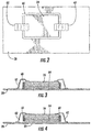
FIG. 2 is a top view of the temperature sensitive component illustrated inFIG. 1 with one embodiment of the thermal switch. -
FIG. 3 is a cross-sectional side view of the temperature sensitive component illustrated inFIG. 2 with the thermal switch in a coupled state. -
FIG. 4 is a cross-sectional side view of the temperature sensitive component illustrated inFIG. 2 with the thermal switch in a decoupled state. -
FIG. 5 is a top view of the temperature sensitive component illustrated inFIG. 1 with another embodiment of the thermal switch. -
FIG. 6 is a cross-sectional side view of the temperature sensitive component illustrated inFIG. 5 with the thermal switch in the coupled state. -
FIG. 7 is a flowchart illustrating a method of maintaining the temperature sensitive component illustrated inFIG. 1 within a temperature range. - The present disclosure will now be described more fully hereinafter with reference to the accompanying drawings, in which preferred embodiments of the disclosure are shown. This invention may, however, be embodied in many different forms and should not be construed as limited to the embodiments set forth herein. Rather, these embodiments are provided so that this disclosure will be thorough and complete, and will fully convey the scope of the invention to those skilled in the art. Like numbers refer to like elements throughout.
- Referring initially to
FIG. 1 , asatellite 20 includes a satellite housing 22, a temperaturesensitive component 24, athermal radiator 28, and athermal switch 30. The temperaturesensitive component 24, thethermal radiator 28, and thethermal switch 30 are carried by the satellite housing 22. The satellite housing 22 may be the main body of thesatellite 20, as illustrated. Alternatively, the satellite housing 22 may be carried on a support arm away from the main body of thesatellite 20. Thesatellite 20 further includescommunications equipment 35 and anantenna 37 coupled thereto. - The
thermal switch 30 is movable between a coupled state and a decoupled stated. In the coupled state, the temperaturesensitive component 24 is thermally coupled to thethermal radiator 28. In the decoupled state, the temperaturesensitive component 24 is thermally decoupled from thethermal radiator 28. When thethermal switch 30 is in the decoupled state, avacuum gap 33 is defined between the temperaturesensitive component 24 and thethermal radiator 28. - The
thermal switch 30 advantageously helps thesatellite 20 conserve DC power when thethermal radiator 28 is thermally decoupled from the temperaturesensitive component 24 while the temperaturesensitive component 24 is being heated by aheater 32. This prevents thethermal switch 30 from radiating valuable heat from the temperaturesensitive component 24 when the temperaturesensitive component 24 is powered off. As a result, less DC power is needed to heat the temperaturesensitive component 24 when thethermal radiator 28 is thermally decoupled from the temperaturesensitive component 24. - The
satellite 20 operates on DC power provided by abattery 34.Solar panels 40 are used to charge thebattery 34. Thesatellite 20 may be a low earth orbit (LEO) satellite, for example. LEO satellites are often referred to as small satellites since they are characterized as having low mass and size. - The
solar panels 40 for a small satellite are limited in size, which means their battery charging capabilities are limited as well. Decoupling thethermal radiator 28 from the temperaturesensitive component 24 allows thesatellite 20 to conserve DC power consumption when operating aheater 32 to heat the temperaturesensitive component 24. - The
heater 32 may be external the temperaturesensitive component 24, as illustrated. Alternatively, theheater 32 may be internal the temperaturesensitive component 24, as readily understood by those skilled in the art. - The
satellite 20 further includes atemperature sensor 42 associated with the temperaturesensitive component 24. Acontroller 50 is configured to operate theheater 32 and thethermal switch 30 based upon thetemperature sensor 42. When thesmall satellite 20 is closer to the earth during its rotation, then it may be shadowed from the sun for about 20 to 30 minutes. Shadowing of thesmall satellite 20 thus contributes to low temperature extremes. - Overall the
small satellite 20 may experience a temperate range of -55EC to +200EC. When the temperaturesensitive component 24 is an electronic circuit device, it is typically limited to a temperature range of -40EC to +85EC, for example, to avoid being damaged. The electronic circuit device may be a microprocessor or a high power amplifier (HPA), for example. When the temperaturesensitive component 24 is a battery, for example, it has an even more limited temperature range. Batteries are typically limited to a temperature range of +10EC to +50EC, for example. - The
thermal switch 30 may be configured as an electromagnetically operated actuator. Referring now toFIGS. 2-4 , one embodiment of the electromagnetically operated actuator will be discussed. The electromagnetically operated actuator comprises asolenoid coil 60, and at least oneflexure mount 62 coupled between the temperaturesensitive component 24 and thethermal radiator 28. In the illustrated embodiment, two flexure mounts 62 are used. - When an electrical current is applied to the
solenoid coil 60, the flexure mounts 62 are switched on, as illustrated inFIG. 3 . When the flexure mounts 62 are switched on, the temperaturesensitive component 24 is thermally coupled to thethermal radiator 28. - To increase the thermal conductance between the temperature
sensitive component 24 and thethermal radiator 28, a compressiblethermal interface layer 64 is carried by the temperaturesensitive component 24. Alternatively, the compressiblethermal interface layer 64 may be carried by thethermal radiator 28. - The compressible
thermal interface layer 64 makes contact with thethermal radiator 28 and the temperaturesensitive component 24 when thethermal switch 30 is in the coupled state. The compressiblethermal interface layer 64 may be indium foil, for example. In another embodiment, the compressiblethermal interface layer 64 may be a thermally conductive pad that is compressible. The thermally conductive pad is compressible since it includes nanotubes or heat springs, for example. A thickness of the compressiblethermal interface layer 64 may be within a range of 3 to 5 mils thick, for example. - When the electrical current is not being applied to the
solenoid coil 60, the flexure mounts 62 are switched off as illustrated inFIG. 4 . When the flexure mounts 62 are switched off, a vacuum gap 66 is between the temperaturesensitive component 24 and thethermal radiator 28. - The electromagnetic force required to activate the electromagnetically operated actuator from the decoupled state to the coupled state is based on the following equation:

- N is the number of turns of the
solenoid coil 60, - I is current applied to the
solenoid coil 60, - µο is the permittivity of the vacuum gap 66,
- µ(IF material) is the permittivity of the compressible
thermal interface layer 64, - A is the contact surface area of the temperature
sensitive component 24, and - gap is the size of the vacuum gap 66.
- An example electromagnetic force for a temperature
sensitive component 24 having a 0.11 cm2 contact surface area is between 30 to 35 psi. In the illustratedthermal switch 30, application of an electrical current causes the temperaturesensitive component 24 to be thermally coupled to thethermal radiator 28. This configured is preferred when thethermal switch 30 is in a normally powered off state. Alternatively, if thethermal switch 30 is in a normally powered on state, then operation of thethermal switch 30 may be reversed. In this case, application of an electrical current causes the temperaturesensitive component 24 to be thermally decoupled from thethermal radiator 28. - Referring now to
FIGS. 5-6 , another embodiment of the electromagnetically operated actuator will be discussed. The electromagnetically operated actuator comprises at least onesolenoid fastener 70 coupled between the temperaturesensitive component 24 and thethermal radiator 28. In the illustrated embodiment, foursolenoid fasteners 70 are used, one adjacent each corner of the temperaturesensitive component 24. - Each
solenoid fastener 70 includesactivation wires 72 contacting anelectromagnetic solenoid bolt 74, and afastener 76 on the back side of thethermal radiator 28. Aconductive plate 78 may be included on a backside of thethermal radiator 28, as illustrated. - When an electrical current is applied to the
activation wires 72, theelectromagnetic solenoid bolts 74 are switched on, as illustrated inFIG. 3 . When theelectromagnetic solenoid bolts 74 are switched on, the temperaturesensitive component 24 is thermally coupled to thethermal radiator 28. When the electrical current is not being applied to theactivation wires 72, theelectromagnetic solenoid bolts 74 are switched off so that a vacuum gap is between the temperaturesensitive component 24 and thethermal radiator 28. - Referring now to
FIG. 7 , a method of maintaining a temperaturesensitive component 24 of asatellite 20 within a temperature range will be discussed in reference to theflowchart 90 inFIG. 7 . From the start (Block 92), the method includes monitoring atemperature sensor 42 associated with the temperaturesensitive component 24 atBlock 94. If the temperaturesensitive component 24 is too hot based upon thetemperature sensor 42, then athermal switch 30 is selectively operated atBlock 96 to a coupled state with the temperaturesensitive component 24 and thethermal radiator 28 being thermally coupled. If the temperaturesensitive component 24 is too cold based upon thetemperature sensor 42, then aheater 32 and thethermal switch 30 are selectively operated atBlock 98 to a decoupled state with the temperaturesensitive component 24 and thethermal radiator 28 being thermally decoupled. The method ends atBlock 100. - Many modifications and other embodiments of the invention will come to the mind of one skilled in the art having the benefit of the teachings presented in the foregoing descriptions and the associated drawings. Therefore, it is understood that the invention is not to be limited to the specific embodiments disclosed, and that modifications and embodiments are intended to be included within the scope of the appended claims.
Claims (10)
- A satellite comprising:a satellite housing;a temperature sensitive component carried by said satellite housing;a thermal radiator carried by said satellite housing; anda thermal switch movable between a coupled state with said temperature sensitive component and said thermal radiator being thermally coupled, and a decoupled state with said temperature sensitive component and said thermal radiator being thermally decoupled.
- The satellite according to Claim 1 wherein said thermal switch, when in the decoupled state, defines a vacuum gap between said temperature sensitive component and said thermal radiator.
- The satellite according to Claim 1 wherein said thermal switch comprises an electromagnetically operated actuator.
- The satellite according to Claim 3 wherein said electromagnetically operated actuator comprises a solenoid coil, and at least one flexure mount coupled between said temperature sensitive component and said thermal radiator.
- The satellite according to Claim 3 wherein said electromagnetically operated actuator comprises at least one solenoid fastener coupled between said temperature sensitive component and said thermal radiator.
- The satellite according to Claim 1 further comprising a compressible thermal interface layer between said temperature sensitive component and said thermal radiator when said thermal switch is in the coupled state.
- The satellite according to Claim 1 further comprising:a temperature sensor associated with said temperature sensitive component; anda controller configured to operate said thermal switch based upon said temperature sensor to maintain said temperature sensitive component within a temperature range.
- A method of maintaining a temperature sensitive component of a satellite within a temperature range, the method comprising:selectively operating a thermal switch movable between a coupled state with the temperature sensitive component and a thermal radiator being thermally coupled, and a decoupled state with the temperature sensitive component and the thermal radiator being thermally decoupled to thereby maintain the temperature sensitive component within the temperature range.
- The method according to Claim 8 wherein the thermal switch, when in the decoupled state, defines a vacuum gap between the temperature sensitive component and the thermal radiator.
- The method according to Claim 8 wherein the thermal switch comprises an electromagnetically operated actuator.
Applications Claiming Priority (1)
| Application Number | Priority Date | Filing Date | Title |
|---|---|---|---|
| US15/687,808 US10865000B2 (en) | 2017-08-28 | 2017-08-28 | Satellite with a thermal switch and associated methods |
Publications (2)
| Publication Number | Publication Date |
|---|---|
| EP3450325A1 true EP3450325A1 (en) | 2019-03-06 |
| EP3450325B1 EP3450325B1 (en) | 2020-10-28 |
Family
ID=63407085
Family Applications (1)
| Application Number | Title | Priority Date | Filing Date |
|---|---|---|---|
| EP18190896.3A Active EP3450325B1 (en) | 2017-08-28 | 2018-08-27 | Satellite with a thermal switch and associated methods |
Country Status (3)
| Country | Link |
|---|---|
| US (2) | US10865000B2 (en) |
| EP (1) | EP3450325B1 (en) |
| KR (1) | KR102317568B1 (en) |
Cited By (2)
| Publication number | Priority date | Publication date | Assignee | Title |
|---|---|---|---|---|
| WO2020182794A1 (en) * | 2019-03-11 | 2020-09-17 | Continental Automotive Gmbh | Thermal diode device for a telematic control unit of a vehicle |
| EP3979776A1 (en) | 2020-10-02 | 2022-04-06 | Commissariat à l'Energie Atomique et aux Energies Alternatives | Thermal switch with passive actuator for thermal link between two elements, on-board system comprising such a switch |
Families Citing this family (5)
| Publication number | Priority date | Publication date | Assignee | Title |
|---|---|---|---|---|
| GB201701833D0 (en) * | 2017-02-03 | 2017-03-22 | Edwards Ltd | Pump cooling systems |
| WO2019055928A1 (en) * | 2017-09-15 | 2019-03-21 | The Government Of The United States Of America, As Represented By The Secretary Of The Navy | Variable conductivity metamaterials and thermal control systems employing the same |
| US11834205B1 (en) * | 2019-11-10 | 2023-12-05 | Space Exploration Technologies Corp. | Spacecraft chassis and component configuration |
| CN111086655B (en) * | 2019-12-16 | 2021-08-24 | 上海卫星工程研究所 | Power saving method and system for thermal control compensation in non-measurement and control arc shadow period |
| CN116812174B (en) * | 2023-05-22 | 2026-03-03 | 东南大学 | Satellite passive thermal management structure based on multistage nonlinear heat conduction |
Citations (7)
| Publication number | Priority date | Publication date | Assignee | Title |
|---|---|---|---|---|
| US3390717A (en) * | 1966-08-02 | 1968-07-02 | Trw Inc | Heat transfer device |
| US3463224A (en) * | 1966-10-24 | 1969-08-26 | Trw Inc | Thermal heat switch |
| US4374402A (en) * | 1980-06-27 | 1983-02-15 | Burroughs Corporation | Piezoelectric transducer mounting structure and associated techniques |
| US5771967A (en) * | 1996-09-12 | 1998-06-30 | The United States Of America As Represented By The Secretary Of The Navy | Wick-interrupt temperature controlling heat pipe |
| EP1006769A2 (en) * | 1998-12-02 | 2000-06-07 | Space Systems / Loral, Inc. | Sequenced heat rejection for body stabilized geosynchronous satellites |
| US20110168378A1 (en) * | 2010-01-14 | 2011-07-14 | Irvine Sensors Corporation | Thermal power distribution system |
| WO2016051786A1 (en) * | 2014-09-30 | 2016-04-07 | パナソニックIpマネジメント株式会社 | Panel unit |
Family Cites Families (11)
| Publication number | Priority date | Publication date | Assignee | Title |
|---|---|---|---|---|
| US3489203A (en) * | 1967-06-01 | 1970-01-13 | Us Navy | Controlled heat pipe |
| JPH01195626A (en) * | 1988-01-29 | 1989-08-07 | Nec Corp | Satellite-mounted thermal switch |
| US5332030A (en) * | 1992-06-25 | 1994-07-26 | Space Systems/Loral, Inc. | Multi-directional cooler |
| US5535815A (en) | 1995-05-24 | 1996-07-16 | The United States Of America As Represented By The Secretary Of The Navy | Package-interface thermal switch |
| US5875096A (en) * | 1997-01-02 | 1999-02-23 | At&T Corp. | Apparatus for heating and cooling an electronic device |
| US5957408A (en) | 1997-12-05 | 1999-09-28 | Space Systems/Loral, Inc. | Satellite with east and west battery radiators |
| DE19852929C1 (en) | 1998-11-17 | 2000-03-30 | Hanning Elektro Werke | Thermal switch for protecting electromagnetic coils in electric motor has connection lugs which enter receptacles of flat pinned plugs from inner surface of end flange of coil |
| US6511021B1 (en) | 2000-08-01 | 2003-01-28 | Nikolus A. Keramidas | Thermal control system for controlling temperature in spacecraft |
| KR100929601B1 (en) | 2001-08-20 | 2009-12-03 | 허니웰 인터내셔널 인코포레이티드 | Snap-In Thermal Switch |
| US6595004B1 (en) | 2002-04-19 | 2003-07-22 | International Business Machines Corporation | Apparatus and methods for performing switching in magnetic refrigeration systems using thermoelectric switches |
| US7967256B2 (en) * | 2007-05-08 | 2011-06-28 | Lockheed Martin Corporation | Spacecraft battery thermal management system |
-
2017
- 2017-08-28 US US15/687,808 patent/US10865000B2/en active Active
-
2018
- 2018-08-27 KR KR1020180100524A patent/KR102317568B1/en active Active
- 2018-08-27 EP EP18190896.3A patent/EP3450325B1/en active Active
-
2020
- 2020-11-09 US US17/092,972 patent/US11459131B2/en active Active
Patent Citations (7)
| Publication number | Priority date | Publication date | Assignee | Title |
|---|---|---|---|---|
| US3390717A (en) * | 1966-08-02 | 1968-07-02 | Trw Inc | Heat transfer device |
| US3463224A (en) * | 1966-10-24 | 1969-08-26 | Trw Inc | Thermal heat switch |
| US4374402A (en) * | 1980-06-27 | 1983-02-15 | Burroughs Corporation | Piezoelectric transducer mounting structure and associated techniques |
| US5771967A (en) * | 1996-09-12 | 1998-06-30 | The United States Of America As Represented By The Secretary Of The Navy | Wick-interrupt temperature controlling heat pipe |
| EP1006769A2 (en) * | 1998-12-02 | 2000-06-07 | Space Systems / Loral, Inc. | Sequenced heat rejection for body stabilized geosynchronous satellites |
| US20110168378A1 (en) * | 2010-01-14 | 2011-07-14 | Irvine Sensors Corporation | Thermal power distribution system |
| WO2016051786A1 (en) * | 2014-09-30 | 2016-04-07 | パナソニックIpマネジメント株式会社 | Panel unit |
Cited By (5)
| Publication number | Priority date | Publication date | Assignee | Title |
|---|---|---|---|---|
| WO2020182794A1 (en) * | 2019-03-11 | 2020-09-17 | Continental Automotive Gmbh | Thermal diode device for a telematic control unit of a vehicle |
| FR3093890A1 (en) * | 2019-03-11 | 2020-09-18 | Continental Automotive Gmbh | Thermal diode device for an electronic unit |
| US12010821B2 (en) | 2019-03-11 | 2024-06-11 | Continental Automotive Gmbh | Thermal diode device for a telematic control unit of a vehicle |
| EP3979776A1 (en) | 2020-10-02 | 2022-04-06 | Commissariat à l'Energie Atomique et aux Energies Alternatives | Thermal switch with passive actuator for thermal link between two elements, on-board system comprising such a switch |
| FR3114871A1 (en) | 2020-10-02 | 2022-04-08 | Commissariat A L Energie Atomique Et Aux Energies Alternatives | Passive actuator thermal switch for thermal connection between two elements, Embedded system comprising such a switch. |
Also Published As
| Publication number | Publication date |
|---|---|
| US20210053701A1 (en) | 2021-02-25 |
| US11459131B2 (en) | 2022-10-04 |
| EP3450325B1 (en) | 2020-10-28 |
| KR102317568B1 (en) | 2021-10-26 |
| US20190061979A1 (en) | 2019-02-28 |
| US10865000B2 (en) | 2020-12-15 |
| KR20190024763A (en) | 2019-03-08 |
Similar Documents
| Publication | Publication Date | Title |
|---|---|---|
| US11459131B2 (en) | Satellite with a thermal switch and associated methods | |
| US7967256B2 (en) | Spacecraft battery thermal management system | |
| JP4513816B2 (en) | Temperature control mechanism and vehicle | |
| US10135110B2 (en) | Vehicle antenna assembly with cooling | |
| US20110117463A1 (en) | Battery temperature control method and assembly | |
| US9025333B1 (en) | Tunable thermal switch | |
| EP2814106B1 (en) | Thermal conductivity control devices | |
| US20160217954A1 (en) | Shape memory circuit breakers | |
| JP2004111370A (en) | Battery thermal control device | |
| US10868345B2 (en) | Battery module and use of such a battery module | |
| EP1052757A2 (en) | Charge control apparatus for a battery pack | |
| US11316217B2 (en) | Configurable thermal conditioning of battery cells | |
| US20200132057A1 (en) | Thermal actuator, and thermal actuator unit | |
| US9490728B1 (en) | Magnetoelectric energy harvesting | |
| DE112007001064B4 (en) | Power supply apparatus | |
| US6867391B2 (en) | Control system for electrostatic discharge mitigation | |
| US12612141B2 (en) | Material-actuated launch and recovery doors | |
| JP7549096B1 (en) | Fire prevention sheet, its manufacturing method, and battery | |
| KR101429748B1 (en) | shielding device of heat sink for a satellite | |
| US20250030061A1 (en) | Pressure control of battery cells | |
| JP2003163482A (en) | Heat-resistant control device | |
| KR20250063419A (en) | Bimetallic cooling structure and Power Relay Assembly using it | |
| CN121922725A (en) | Method for manufacturing electric storage device | |
| WO2026048233A1 (en) | Fire-spread prevention sheet, method for manufacturing same, and battery | |
| Tsuyuki et al. | Mars exploration rover: Thermal design is a system engineering activity |
Legal Events
| Date | Code | Title | Description |
|---|---|---|---|
| PUAI | Public reference made under article 153(3) epc to a published international application that has entered the european phase |
Free format text: ORIGINAL CODE: 0009012 |
|
| STAA | Information on the status of an ep patent application or granted ep patent |
Free format text: STATUS: REQUEST FOR EXAMINATION WAS MADE |
|
| 17P | Request for examination filed |
Effective date: 20180827 |
|
| AK | Designated contracting states |
Kind code of ref document: A1 Designated state(s): AL AT BE BG CH CY CZ DE DK EE ES FI FR GB GR HR HU IE IS IT LI LT LU LV MC MK MT NL NO PL PT RO RS SE SI SK SM TR |
|
| AX | Request for extension of the european patent |
Extension state: BA ME |
|
| STAA | Information on the status of an ep patent application or granted ep patent |
Free format text: STATUS: EXAMINATION IS IN PROGRESS |
|
| 17Q | First examination report despatched |
Effective date: 20191021 |
|
| REG | Reference to a national code |
Ref country code: DE Ref legal event code: R079 Ref document number: 602018009087 Country of ref document: DE Free format text: PREVIOUS MAIN CLASS: B64G0001100000 Ipc: B64G0001500000 |
|
| GRAP | Despatch of communication of intention to grant a patent |
Free format text: ORIGINAL CODE: EPIDOSNIGR1 |
|
| STAA | Information on the status of an ep patent application or granted ep patent |
Free format text: STATUS: GRANT OF PATENT IS INTENDED |
|
| RIC1 | Information provided on ipc code assigned before grant |
Ipc: B64G 1/50 20060101AFI20200324BHEP Ipc: B64G 1/10 20060101ALI20200324BHEP |
|
| INTG | Intention to grant announced |
Effective date: 20200417 |
|
| GRAS | Grant fee paid |
Free format text: ORIGINAL CODE: EPIDOSNIGR3 |
|
| GRAJ | Information related to disapproval of communication of intention to grant by the applicant or resumption of examination proceedings by the epo deleted |
Free format text: ORIGINAL CODE: EPIDOSDIGR1 |
|
| GRAL | Information related to payment of fee for publishing/printing deleted |
Free format text: ORIGINAL CODE: EPIDOSDIGR3 |
|
| STAA | Information on the status of an ep patent application or granted ep patent |
Free format text: STATUS: EXAMINATION IS IN PROGRESS |
|
| GRAP | Despatch of communication of intention to grant a patent |
Free format text: ORIGINAL CODE: EPIDOSNIGR1 |
|
| STAA | Information on the status of an ep patent application or granted ep patent |
Free format text: STATUS: GRANT OF PATENT IS INTENDED |
|
| INTC | Intention to grant announced (deleted) | ||
| INTG | Intention to grant announced |
Effective date: 20200812 |
|
| GRAA | (expected) grant |
Free format text: ORIGINAL CODE: 0009210 |
|
| STAA | Information on the status of an ep patent application or granted ep patent |
Free format text: STATUS: THE PATENT HAS BEEN GRANTED |
|
| AK | Designated contracting states |
Kind code of ref document: B1 Designated state(s): AL AT BE BG CH CY CZ DE DK EE ES FI FR GB GR HR HU IE IS IT LI LT LU LV MC MK MT NL NO PL PT RO RS SE SI SK SM TR |
|
| REG | Reference to a national code |
Ref country code: GB Ref legal event code: FG4D |
|
| REG | Reference to a national code |
Ref country code: CH Ref legal event code: EP |
|
| REG | Reference to a national code |
Ref country code: DE Ref legal event code: R096 Ref document number: 602018009087 Country of ref document: DE |
|
| REG | Reference to a national code |
Ref country code: AT Ref legal event code: REF Ref document number: 1327984 Country of ref document: AT Kind code of ref document: T Effective date: 20201115 |
|
| REG | Reference to a national code |
Ref country code: IE Ref legal event code: FG4D |
|
| REG | Reference to a national code |
Ref country code: AT Ref legal event code: MK05 Ref document number: 1327984 Country of ref document: AT Kind code of ref document: T Effective date: 20201028 |
|
| REG | Reference to a national code |
Ref country code: NL Ref legal event code: MP Effective date: 20201028 |
|
| PG25 | Lapsed in a contracting state [announced via postgrant information from national office to epo] |
Ref country code: NO Free format text: LAPSE BECAUSE OF FAILURE TO SUBMIT A TRANSLATION OF THE DESCRIPTION OR TO PAY THE FEE WITHIN THE PRESCRIBED TIME-LIMIT Effective date: 20210128 Ref country code: GR Free format text: LAPSE BECAUSE OF FAILURE TO SUBMIT A TRANSLATION OF THE DESCRIPTION OR TO PAY THE FEE WITHIN THE PRESCRIBED TIME-LIMIT Effective date: 20210129 Ref country code: FI Free format text: LAPSE BECAUSE OF FAILURE TO SUBMIT A TRANSLATION OF THE DESCRIPTION OR TO PAY THE FEE WITHIN THE PRESCRIBED TIME-LIMIT Effective date: 20201028 Ref country code: RS Free format text: LAPSE BECAUSE OF FAILURE TO SUBMIT A TRANSLATION OF THE DESCRIPTION OR TO PAY THE FEE WITHIN THE PRESCRIBED TIME-LIMIT Effective date: 20201028 Ref country code: PT Free format text: LAPSE BECAUSE OF FAILURE TO SUBMIT A TRANSLATION OF THE DESCRIPTION OR TO PAY THE FEE WITHIN THE PRESCRIBED TIME-LIMIT Effective date: 20210301 |
|
| REG | Reference to a national code |
Ref country code: LT Ref legal event code: MG4D |
|
| PG25 | Lapsed in a contracting state [announced via postgrant information from national office to epo] |
Ref country code: SE Free format text: LAPSE BECAUSE OF FAILURE TO SUBMIT A TRANSLATION OF THE DESCRIPTION OR TO PAY THE FEE WITHIN THE PRESCRIBED TIME-LIMIT Effective date: 20201028 Ref country code: PL Free format text: LAPSE BECAUSE OF FAILURE TO SUBMIT A TRANSLATION OF THE DESCRIPTION OR TO PAY THE FEE WITHIN THE PRESCRIBED TIME-LIMIT Effective date: 20201028 Ref country code: IS Free format text: LAPSE BECAUSE OF FAILURE TO SUBMIT A TRANSLATION OF THE DESCRIPTION OR TO PAY THE FEE WITHIN THE PRESCRIBED TIME-LIMIT Effective date: 20210228 Ref country code: LV Free format text: LAPSE BECAUSE OF FAILURE TO SUBMIT A TRANSLATION OF THE DESCRIPTION OR TO PAY THE FEE WITHIN THE PRESCRIBED TIME-LIMIT Effective date: 20201028 Ref country code: BG Free format text: LAPSE BECAUSE OF FAILURE TO SUBMIT A TRANSLATION OF THE DESCRIPTION OR TO PAY THE FEE WITHIN THE PRESCRIBED TIME-LIMIT Effective date: 20210128 Ref country code: ES Free format text: LAPSE BECAUSE OF FAILURE TO SUBMIT A TRANSLATION OF THE DESCRIPTION OR TO PAY THE FEE WITHIN THE PRESCRIBED TIME-LIMIT Effective date: 20201028 Ref country code: AT Free format text: LAPSE BECAUSE OF FAILURE TO SUBMIT A TRANSLATION OF THE DESCRIPTION OR TO PAY THE FEE WITHIN THE PRESCRIBED TIME-LIMIT Effective date: 20201028 |
|
| PG25 | Lapsed in a contracting state [announced via postgrant information from national office to epo] |
Ref country code: HR Free format text: LAPSE BECAUSE OF FAILURE TO SUBMIT A TRANSLATION OF THE DESCRIPTION OR TO PAY THE FEE WITHIN THE PRESCRIBED TIME-LIMIT Effective date: 20201028 Ref country code: NL Free format text: LAPSE BECAUSE OF FAILURE TO SUBMIT A TRANSLATION OF THE DESCRIPTION OR TO PAY THE FEE WITHIN THE PRESCRIBED TIME-LIMIT Effective date: 20201028 |
|
| REG | Reference to a national code |
Ref country code: DE Ref legal event code: R097 Ref document number: 602018009087 Country of ref document: DE |
|
| PG25 | Lapsed in a contracting state [announced via postgrant information from national office to epo] |
Ref country code: SK Free format text: LAPSE BECAUSE OF FAILURE TO SUBMIT A TRANSLATION OF THE DESCRIPTION OR TO PAY THE FEE WITHIN THE PRESCRIBED TIME-LIMIT Effective date: 20201028 Ref country code: RO Free format text: LAPSE BECAUSE OF FAILURE TO SUBMIT A TRANSLATION OF THE DESCRIPTION OR TO PAY THE FEE WITHIN THE PRESCRIBED TIME-LIMIT Effective date: 20201028 Ref country code: LT Free format text: LAPSE BECAUSE OF FAILURE TO SUBMIT A TRANSLATION OF THE DESCRIPTION OR TO PAY THE FEE WITHIN THE PRESCRIBED TIME-LIMIT Effective date: 20201028 Ref country code: EE Free format text: LAPSE BECAUSE OF FAILURE TO SUBMIT A TRANSLATION OF THE DESCRIPTION OR TO PAY THE FEE WITHIN THE PRESCRIBED TIME-LIMIT Effective date: 20201028 Ref country code: CZ Free format text: LAPSE BECAUSE OF FAILURE TO SUBMIT A TRANSLATION OF THE DESCRIPTION OR TO PAY THE FEE WITHIN THE PRESCRIBED TIME-LIMIT Effective date: 20201028 Ref country code: SM Free format text: LAPSE BECAUSE OF FAILURE TO SUBMIT A TRANSLATION OF THE DESCRIPTION OR TO PAY THE FEE WITHIN THE PRESCRIBED TIME-LIMIT Effective date: 20201028 |
|
| PG25 | Lapsed in a contracting state [announced via postgrant information from national office to epo] |
Ref country code: DK Free format text: LAPSE BECAUSE OF FAILURE TO SUBMIT A TRANSLATION OF THE DESCRIPTION OR TO PAY THE FEE WITHIN THE PRESCRIBED TIME-LIMIT Effective date: 20201028 |
|
| PLBE | No opposition filed within time limit |
Free format text: ORIGINAL CODE: 0009261 |
|
| STAA | Information on the status of an ep patent application or granted ep patent |
Free format text: STATUS: NO OPPOSITION FILED WITHIN TIME LIMIT |
|
| 26N | No opposition filed |
Effective date: 20210729 |
|
| PG25 | Lapsed in a contracting state [announced via postgrant information from national office to epo] |
Ref country code: AL Free format text: LAPSE BECAUSE OF FAILURE TO SUBMIT A TRANSLATION OF THE DESCRIPTION OR TO PAY THE FEE WITHIN THE PRESCRIBED TIME-LIMIT Effective date: 20201028 Ref country code: IT Free format text: LAPSE BECAUSE OF FAILURE TO SUBMIT A TRANSLATION OF THE DESCRIPTION OR TO PAY THE FEE WITHIN THE PRESCRIBED TIME-LIMIT Effective date: 20201028 |
|
| PG25 | Lapsed in a contracting state [announced via postgrant information from national office to epo] |
Ref country code: SI Free format text: LAPSE BECAUSE OF FAILURE TO SUBMIT A TRANSLATION OF THE DESCRIPTION OR TO PAY THE FEE WITHIN THE PRESCRIBED TIME-LIMIT Effective date: 20201028 |
|
| REG | Reference to a national code |
Ref country code: CH Ref legal event code: PL |
|
| PG25 | Lapsed in a contracting state [announced via postgrant information from national office to epo] |
Ref country code: MC Free format text: LAPSE BECAUSE OF FAILURE TO SUBMIT A TRANSLATION OF THE DESCRIPTION OR TO PAY THE FEE WITHIN THE PRESCRIBED TIME-LIMIT Effective date: 20201028 |
|
| REG | Reference to a national code |
Ref country code: BE Ref legal event code: MM Effective date: 20210831 |
|
| PG25 | Lapsed in a contracting state [announced via postgrant information from national office to epo] |
Ref country code: LI Free format text: LAPSE BECAUSE OF NON-PAYMENT OF DUE FEES Effective date: 20210831 Ref country code: CH Free format text: LAPSE BECAUSE OF NON-PAYMENT OF DUE FEES Effective date: 20210831 |
|
| PG25 | Lapsed in a contracting state [announced via postgrant information from national office to epo] |
Ref country code: IS Free format text: LAPSE BECAUSE OF FAILURE TO SUBMIT A TRANSLATION OF THE DESCRIPTION OR TO PAY THE FEE WITHIN THE PRESCRIBED TIME-LIMIT Effective date: 20210228 Ref country code: LU Free format text: LAPSE BECAUSE OF NON-PAYMENT OF DUE FEES Effective date: 20210827 |
|
| PG25 | Lapsed in a contracting state [announced via postgrant information from national office to epo] |
Ref country code: IE Free format text: LAPSE BECAUSE OF NON-PAYMENT OF DUE FEES Effective date: 20210827 Ref country code: BE Free format text: LAPSE BECAUSE OF NON-PAYMENT OF DUE FEES Effective date: 20210831 |
|
| PG25 | Lapsed in a contracting state [announced via postgrant information from national office to epo] |
Ref country code: CY Free format text: LAPSE BECAUSE OF FAILURE TO SUBMIT A TRANSLATION OF THE DESCRIPTION OR TO PAY THE FEE WITHIN THE PRESCRIBED TIME-LIMIT Effective date: 20201028 |
|
| P01 | Opt-out of the competence of the unified patent court (upc) registered |
Effective date: 20230530 |
|
| PG25 | Lapsed in a contracting state [announced via postgrant information from national office to epo] |
Ref country code: HU Free format text: LAPSE BECAUSE OF FAILURE TO SUBMIT A TRANSLATION OF THE DESCRIPTION OR TO PAY THE FEE WITHIN THE PRESCRIBED TIME-LIMIT; INVALID AB INITIO Effective date: 20180827 |
|
| PG25 | Lapsed in a contracting state [announced via postgrant information from national office to epo] |
Ref country code: MK Free format text: LAPSE BECAUSE OF FAILURE TO SUBMIT A TRANSLATION OF THE DESCRIPTION OR TO PAY THE FEE WITHIN THE PRESCRIBED TIME-LIMIT Effective date: 20201028 |
|
| PG25 | Lapsed in a contracting state [announced via postgrant information from national office to epo] |
Ref country code: MT Free format text: LAPSE BECAUSE OF FAILURE TO SUBMIT A TRANSLATION OF THE DESCRIPTION OR TO PAY THE FEE WITHIN THE PRESCRIBED TIME-LIMIT Effective date: 20201028 |
|
| PGFP | Annual fee paid to national office [announced via postgrant information from national office to epo] |
Ref country code: DE Payment date: 20250827 Year of fee payment: 8 |
|
| PGFP | Annual fee paid to national office [announced via postgrant information from national office to epo] |
Ref country code: GB Payment date: 20250827 Year of fee payment: 8 |
|
| PGFP | Annual fee paid to national office [announced via postgrant information from national office to epo] |
Ref country code: FR Payment date: 20250825 Year of fee payment: 8 |
|
| PG25 | Lapsed in a contracting state [announced via postgrant information from national office to epo] |
Ref country code: TR Free format text: LAPSE BECAUSE OF FAILURE TO SUBMIT A TRANSLATION OF THE DESCRIPTION OR TO PAY THE FEE WITHIN THE PRESCRIBED TIME-LIMIT Effective date: 20201028 |