EP3450255A1 - Around view monitoring apparatus for vehicle, and vehicle - Google Patents
Around view monitoring apparatus for vehicle, and vehicle Download PDFInfo
- Publication number
- EP3450255A1 EP3450255A1 EP18184431.7A EP18184431A EP3450255A1 EP 3450255 A1 EP3450255 A1 EP 3450255A1 EP 18184431 A EP18184431 A EP 18184431A EP 3450255 A1 EP3450255 A1 EP 3450255A1
- Authority
- EP
- European Patent Office
- Prior art keywords
- image
- vehicle
- region
- camera
- processor
- Prior art date
- Legal status (The legal status is an assumption and is not a legal conclusion. Google has not performed a legal analysis and makes no representation as to the accuracy of the status listed.)
- Ceased
Links
Images













Classifications
-
- B—PERFORMING OPERATIONS; TRANSPORTING
- B60—VEHICLES IN GENERAL
- B60W—CONJOINT CONTROL OF VEHICLE SUB-UNITS OF DIFFERENT TYPE OR DIFFERENT FUNCTION; CONTROL SYSTEMS SPECIALLY ADAPTED FOR HYBRID VEHICLES; ROAD VEHICLE DRIVE CONTROL SYSTEMS FOR PURPOSES NOT RELATED TO THE CONTROL OF A PARTICULAR SUB-UNIT
- B60W40/00—Estimation or calculation of non-directly measurable driving parameters for road vehicle drive control systems not related to the control of a particular sub unit, e.g. by using mathematical models
- B60W40/02—Estimation or calculation of non-directly measurable driving parameters for road vehicle drive control systems not related to the control of a particular sub unit, e.g. by using mathematical models related to ambient conditions
-
- B—PERFORMING OPERATIONS; TRANSPORTING
- B60—VEHICLES IN GENERAL
- B60R—VEHICLES, VEHICLE FITTINGS, OR VEHICLE PARTS, NOT OTHERWISE PROVIDED FOR
- B60R1/00—Optical viewing arrangements; Real-time viewing arrangements for drivers or passengers using optical image capturing systems, e.g. cameras or video systems specially adapted for use in or on vehicles
- B60R1/20—Real-time viewing arrangements for drivers or passengers using optical image capturing systems, e.g. cameras or video systems specially adapted for use in or on vehicles
- B60R1/22—Real-time viewing arrangements for drivers or passengers using optical image capturing systems, e.g. cameras or video systems specially adapted for use in or on vehicles for viewing an area outside the vehicle, e.g. the exterior of the vehicle
- B60R1/23—Real-time viewing arrangements for drivers or passengers using optical image capturing systems, e.g. cameras or video systems specially adapted for use in or on vehicles for viewing an area outside the vehicle, e.g. the exterior of the vehicle with a predetermined field of view
- B60R1/27—Real-time viewing arrangements for drivers or passengers using optical image capturing systems, e.g. cameras or video systems specially adapted for use in or on vehicles for viewing an area outside the vehicle, e.g. the exterior of the vehicle with a predetermined field of view providing all-round vision, e.g. using omnidirectional cameras
-
- B—PERFORMING OPERATIONS; TRANSPORTING
- B60—VEHICLES IN GENERAL
- B60R—VEHICLES, VEHICLE FITTINGS, OR VEHICLE PARTS, NOT OTHERWISE PROVIDED FOR
- B60R1/00—Optical viewing arrangements; Real-time viewing arrangements for drivers or passengers using optical image capturing systems, e.g. cameras or video systems specially adapted for use in or on vehicles
-
- B—PERFORMING OPERATIONS; TRANSPORTING
- B60—VEHICLES IN GENERAL
- B60R—VEHICLES, VEHICLE FITTINGS, OR VEHICLE PARTS, NOT OTHERWISE PROVIDED FOR
- B60R1/00—Optical viewing arrangements; Real-time viewing arrangements for drivers or passengers using optical image capturing systems, e.g. cameras or video systems specially adapted for use in or on vehicles
- B60R1/20—Real-time viewing arrangements for drivers or passengers using optical image capturing systems, e.g. cameras or video systems specially adapted for use in or on vehicles
- B60R1/22—Real-time viewing arrangements for drivers or passengers using optical image capturing systems, e.g. cameras or video systems specially adapted for use in or on vehicles for viewing an area outside the vehicle, e.g. the exterior of the vehicle
- B60R1/23—Real-time viewing arrangements for drivers or passengers using optical image capturing systems, e.g. cameras or video systems specially adapted for use in or on vehicles for viewing an area outside the vehicle, e.g. the exterior of the vehicle with a predetermined field of view
- B60R1/26—Real-time viewing arrangements for drivers or passengers using optical image capturing systems, e.g. cameras or video systems specially adapted for use in or on vehicles for viewing an area outside the vehicle, e.g. the exterior of the vehicle with a predetermined field of view to the rear of the vehicle
-
- B—PERFORMING OPERATIONS; TRANSPORTING
- B60—VEHICLES IN GENERAL
- B60R—VEHICLES, VEHICLE FITTINGS, OR VEHICLE PARTS, NOT OTHERWISE PROVIDED FOR
- B60R1/00—Optical viewing arrangements; Real-time viewing arrangements for drivers or passengers using optical image capturing systems, e.g. cameras or video systems specially adapted for use in or on vehicles
- B60R1/20—Real-time viewing arrangements for drivers or passengers using optical image capturing systems, e.g. cameras or video systems specially adapted for use in or on vehicles
- B60R1/22—Real-time viewing arrangements for drivers or passengers using optical image capturing systems, e.g. cameras or video systems specially adapted for use in or on vehicles for viewing an area outside the vehicle, e.g. the exterior of the vehicle
- B60R1/28—Real-time viewing arrangements for drivers or passengers using optical image capturing systems, e.g. cameras or video systems specially adapted for use in or on vehicles for viewing an area outside the vehicle, e.g. the exterior of the vehicle with an adjustable field of view
-
- G—PHYSICS
- G02—OPTICS
- G02B—OPTICAL ELEMENTS, SYSTEMS OR APPARATUS
- G02B13/00—Optical objectives specially designed for the purposes specified below
- G02B13/001—Miniaturised objectives for electronic devices, e.g. portable telephones, webcams, PDAs, small digital cameras
- G02B13/0055—Miniaturised objectives for electronic devices, e.g. portable telephones, webcams, PDAs, small digital cameras employing a special optical element
- G02B13/0075—Miniaturised objectives for electronic devices, e.g. portable telephones, webcams, PDAs, small digital cameras employing a special optical element having an element with variable optical properties
-
- G—PHYSICS
- G03—PHOTOGRAPHY; CINEMATOGRAPHY; ANALOGOUS TECHNIQUES USING WAVES OTHER THAN OPTICAL WAVES; ELECTROGRAPHY; HOLOGRAPHY
- G03B—APPARATUS OR ARRANGEMENTS FOR TAKING PHOTOGRAPHS OR FOR PROJECTING OR VIEWING THEM; APPARATUS OR ARRANGEMENTS EMPLOYING ANALOGOUS TECHNIQUES USING WAVES OTHER THAN OPTICAL WAVES; ACCESSORIES THEREFOR
- G03B13/00—Viewfinders; Focusing aids for cameras; Means for focusing for cameras; Autofocus systems for cameras
- G03B13/32—Means for focusing
-
- G—PHYSICS
- G06—COMPUTING OR CALCULATING; COUNTING
- G06T—IMAGE DATA PROCESSING OR GENERATION, IN GENERAL
- G06T7/00—Image analysis
- G06T7/10—Segmentation; Edge detection
- G06T7/11—Region-based segmentation
-
- G—PHYSICS
- G06—COMPUTING OR CALCULATING; COUNTING
- G06T—IMAGE DATA PROCESSING OR GENERATION, IN GENERAL
- G06T7/00—Image analysis
- G06T7/10—Segmentation; Edge detection
- G06T7/174—Segmentation; Edge detection involving the use of two or more images
-
- H—ELECTRICITY
- H04—ELECTRIC COMMUNICATION TECHNIQUE
- H04N—PICTORIAL COMMUNICATION, e.g. TELEVISION
- H04N23/00—Cameras or camera modules comprising electronic image sensors; Control thereof
- H04N23/50—Constructional details
- H04N23/54—Mounting of pick-up tubes, electronic image sensors, deviation or focusing coils
-
- H—ELECTRICITY
- H04—ELECTRIC COMMUNICATION TECHNIQUE
- H04N—PICTORIAL COMMUNICATION, e.g. TELEVISION
- H04N23/00—Cameras or camera modules comprising electronic image sensors; Control thereof
- H04N23/50—Constructional details
- H04N23/55—Optical parts specially adapted for electronic image sensors; Mounting thereof
-
- H—ELECTRICITY
- H04—ELECTRIC COMMUNICATION TECHNIQUE
- H04N—PICTORIAL COMMUNICATION, e.g. TELEVISION
- H04N23/00—Cameras or camera modules comprising electronic image sensors; Control thereof
- H04N23/57—Mechanical or electrical details of cameras or camera modules specially adapted for being embedded in other devices
-
- H—ELECTRICITY
- H04—ELECTRIC COMMUNICATION TECHNIQUE
- H04N—PICTORIAL COMMUNICATION, e.g. TELEVISION
- H04N23/00—Cameras or camera modules comprising electronic image sensors; Control thereof
- H04N23/58—Means for changing the camera field of view without moving the camera body, e.g. nutating or panning of optics or image sensors
-
- H—ELECTRICITY
- H04—ELECTRIC COMMUNICATION TECHNIQUE
- H04N—PICTORIAL COMMUNICATION, e.g. TELEVISION
- H04N23/00—Cameras or camera modules comprising electronic image sensors; Control thereof
- H04N23/60—Control of cameras or camera modules
- H04N23/62—Control of parameters via user interfaces
-
- H—ELECTRICITY
- H04—ELECTRIC COMMUNICATION TECHNIQUE
- H04N—PICTORIAL COMMUNICATION, e.g. TELEVISION
- H04N23/00—Cameras or camera modules comprising electronic image sensors; Control thereof
- H04N23/60—Control of cameras or camera modules
- H04N23/698—Control of cameras or camera modules for achieving an enlarged field of view, e.g. panoramic image capture
-
- H—ELECTRICITY
- H04—ELECTRIC COMMUNICATION TECHNIQUE
- H04N—PICTORIAL COMMUNICATION, e.g. TELEVISION
- H04N23/00—Cameras or camera modules comprising electronic image sensors; Control thereof
- H04N23/90—Arrangement of cameras or camera modules, e.g. multiple cameras in TV studios or sports stadiums
-
- H—ELECTRICITY
- H04—ELECTRIC COMMUNICATION TECHNIQUE
- H04N—PICTORIAL COMMUNICATION, e.g. TELEVISION
- H04N7/00—Television systems
- H04N7/18—Closed-circuit television [CCTV] systems, i.e. systems in which the video signal is not broadcast
- H04N7/181—Closed-circuit television [CCTV] systems, i.e. systems in which the video signal is not broadcast for receiving images from a plurality of remote sources
-
- B—PERFORMING OPERATIONS; TRANSPORTING
- B60—VEHICLES IN GENERAL
- B60R—VEHICLES, VEHICLE FITTINGS, OR VEHICLE PARTS, NOT OTHERWISE PROVIDED FOR
- B60R2300/00—Details of viewing arrangements using cameras and displays, specially adapted for use in a vehicle
- B60R2300/10—Details of viewing arrangements using cameras and displays, specially adapted for use in a vehicle characterised by the type of camera system used
- B60R2300/105—Details of viewing arrangements using cameras and displays, specially adapted for use in a vehicle characterised by the type of camera system used using multiple cameras
-
- B—PERFORMING OPERATIONS; TRANSPORTING
- B60—VEHICLES IN GENERAL
- B60R—VEHICLES, VEHICLE FITTINGS, OR VEHICLE PARTS, NOT OTHERWISE PROVIDED FOR
- B60R2300/00—Details of viewing arrangements using cameras and displays, specially adapted for use in a vehicle
- B60R2300/20—Details of viewing arrangements using cameras and displays, specially adapted for use in a vehicle characterised by the type of display used
-
- B—PERFORMING OPERATIONS; TRANSPORTING
- B60—VEHICLES IN GENERAL
- B60R—VEHICLES, VEHICLE FITTINGS, OR VEHICLE PARTS, NOT OTHERWISE PROVIDED FOR
- B60R2300/00—Details of viewing arrangements using cameras and displays, specially adapted for use in a vehicle
- B60R2300/30—Details of viewing arrangements using cameras and displays, specially adapted for use in a vehicle characterised by the type of image processing
- B60R2300/303—Details of viewing arrangements using cameras and displays, specially adapted for use in a vehicle characterised by the type of image processing using joined images, e.g. multiple camera images
-
- B—PERFORMING OPERATIONS; TRANSPORTING
- B60—VEHICLES IN GENERAL
- B60R—VEHICLES, VEHICLE FITTINGS, OR VEHICLE PARTS, NOT OTHERWISE PROVIDED FOR
- B60R2300/00—Details of viewing arrangements using cameras and displays, specially adapted for use in a vehicle
- B60R2300/30—Details of viewing arrangements using cameras and displays, specially adapted for use in a vehicle characterised by the type of image processing
- B60R2300/306—Details of viewing arrangements using cameras and displays, specially adapted for use in a vehicle characterised by the type of image processing using a re-scaling of images
-
- B—PERFORMING OPERATIONS; TRANSPORTING
- B60—VEHICLES IN GENERAL
- B60R—VEHICLES, VEHICLE FITTINGS, OR VEHICLE PARTS, NOT OTHERWISE PROVIDED FOR
- B60R2300/00—Details of viewing arrangements using cameras and displays, specially adapted for use in a vehicle
- B60R2300/80—Details of viewing arrangements using cameras and displays, specially adapted for use in a vehicle characterised by the intended use of the viewing arrangement
- B60R2300/8066—Details of viewing arrangements using cameras and displays, specially adapted for use in a vehicle characterised by the intended use of the viewing arrangement for monitoring rearward traffic
-
- B—PERFORMING OPERATIONS; TRANSPORTING
- B60—VEHICLES IN GENERAL
- B60W—CONJOINT CONTROL OF VEHICLE SUB-UNITS OF DIFFERENT TYPE OR DIFFERENT FUNCTION; CONTROL SYSTEMS SPECIALLY ADAPTED FOR HYBRID VEHICLES; ROAD VEHICLE DRIVE CONTROL SYSTEMS FOR PURPOSES NOT RELATED TO THE CONTROL OF A PARTICULAR SUB-UNIT
- B60W50/00—Details of control systems for road vehicle drive control not related to the control of a particular sub-unit, e.g. process diagnostic or vehicle driver interfaces
- B60W50/08—Interaction between the driver and the control system
- B60W50/14—Means for informing the driver, warning the driver or prompting a driver intervention
- B60W2050/146—Display means
-
- B—PERFORMING OPERATIONS; TRANSPORTING
- B60—VEHICLES IN GENERAL
- B60W—CONJOINT CONTROL OF VEHICLE SUB-UNITS OF DIFFERENT TYPE OR DIFFERENT FUNCTION; CONTROL SYSTEMS SPECIALLY ADAPTED FOR HYBRID VEHICLES; ROAD VEHICLE DRIVE CONTROL SYSTEMS FOR PURPOSES NOT RELATED TO THE CONTROL OF A PARTICULAR SUB-UNIT
- B60W2420/00—Indexing codes relating to the type of sensors based on the principle of their operation
- B60W2420/40—Photo, light or radio wave sensitive means, e.g. infrared sensors
- B60W2420/403—Image sensing, e.g. optical camera
-
- G—PHYSICS
- G02—OPTICS
- G02B—OPTICAL ELEMENTS, SYSTEMS OR APPARATUS
- G02B27/00—Optical systems or apparatus not provided for by any of the groups G02B1/00 - G02B26/00, G02B30/00
- G02B27/10—Beam splitting or combining systems
- G02B27/12—Beam splitting or combining systems operating by refraction only
- G02B27/126—The splitting element being a prism or prismatic array, including systems based on total internal reflection
-
- G—PHYSICS
- G05—CONTROLLING; REGULATING
- G05D—SYSTEMS FOR CONTROLLING OR REGULATING NON-ELECTRIC VARIABLES
- G05D1/00—Control of position, course, altitude or attitude of land, water, air or space vehicles, e.g. using automatic pilots
- G05D1/02—Control of position or course in two dimensions
- G05D1/021—Control of position or course in two dimensions specially adapted to land vehicles
- G05D1/0231—Control of position or course in two dimensions specially adapted to land vehicles using optical position detecting means
- G05D1/0246—Control of position or course in two dimensions specially adapted to land vehicles using optical position detecting means using a video camera in combination with image processing means
Definitions
- the present invention relates to an around view monitoring apparatus for a vehicle, and a vehicle including the same.
- a vehicle allows a user who rides therein to drive the vehicle in a desired direction.
- a representative example of the vehicle may be an automobile.
- the vehicle is provided with, for example, various sensors and electronic devices.
- ADASs advanced driver assistance systems
- development of autonomous vehicles has been actively conducted.
- the vehicle may include several cameras.
- each camera has an angle of view and resolution suitable for a function to be implemented.
- the vehicle may include an around view monitoring camera and a camera for detecting a forward object.
- an around view monitoring apparatus including a plurality of cameras and a processor configured to process a plurality of images acquired through the plurality of cameras, wherein one or more of the plurality of cameras includes a lens unit configured to enable focal lengths of two or more regions included in the acquired images to be different from each other.
- an around view monitoring apparatus comprising a plurality of cameras; and a processor configured to process a plurality of images acquired through the plurality of cameras, wherein one or more of the plurality of cameras includes a lens unit configured to enable focal lengths of two or more regions included in the acquired images to be different from each other.
- the image includes a first region having a relatively narrow angle and a second region having a relative wide angle.
- the processor is configured to split and to process the first region and the second region.
- the processor is configured to generate a narrow-angle image based on the first region, and synthesize the first region and the second region based on a mapping function to generate a wide-angle image.
- the monitoring apparatus comprises an interface configured to exchange data with one or more devices in a vehicle, wherein the processor provides the narrow-angle image and the wide-angle image to the one or more devices.
- the processor is configured to alternately provide the narrow-angle image and the wide-angle image to the devices in frame units or slice units.
- the interface includes a first port and a second port.
- the processor is configured to provide the narrow-angle image through the first port.
- the processor is configured to provide the wide-angle image through the second port.
- the monitoring apparatus comprises a display unit.
- the processor is configured to control the display unit to display an image based on the narrow-angle image and the wide-angle image.
- one or more of the plurality of cameras includes an image sensor including two or more pixel arrays formed in correspondence with the two or more regions and configured to convert light input to the two or more pixel arrays through the lens unit into an electrical signal.
- the two or more pixel arrays have different pixel densities.
- the plurality of cameras includes a front camera configured to acquire a front image of a vehicle.
- the front camera includes a first lens unit configured to enable focal lengths of a central region and a peripheral region of the front image to be different from each other.
- a vertical angle of view of the front image is equal to a horizontal angle of view thereof.
- the front camera includes a first image sensor including a first pixel array corresponding to the central region and a second image sensor corresponding to the peripheral region.
- a pixel density of the first pixel array is different from that of the second pixel array.
- the processor performs lens distortion correction with respect to the front image.
- the plurality of cameras includes a rear camera configured to acquire a rear image of a vehicle.
- the rear camera includes a second lens unit configured to enable a focal length of a whole region of the acquired image to be constant.
- a vertical angle of view of the rear image is equal to a horizontal angle of view thereof.
- the plurality of cameras includes a left camera configured to acquire a left image of a vehicle.
- the left camera includes a third lens unit configured to enable focal lengths of a right region and a left region of the left image to be different from each other.
- the left camera includes a third image sensor including a third pixel array corresponding to the right region and a fourth pixel array corresponding to the left region.
- a pixel density of the third pixel array is different from that of the fourth pixel array.
- the plurality of cameras includes a right camera configured to acquire a right image of a vehicle.
- the right camera includes a fourth lens unit configured to enable focal lengths of a left region and a right region of the image acquired through the right camera to be different from each other.
- the right camera includes a fourth image sensor including a fifth pixel array corresponding to the left region and a sixth pixel array corresponding to the right region.
- a pixel density of the fifth pixel array is different from that of the sixth pixel array.
- the term 'have', 'may have', 'include', or 'may include' signifies the presence of a specific feature, number, step, operation, component, or part, or their combinations, not excluding the presence or addition of one or more other features, numbers, steps, operations, components, or parts, or their combinations.
- a vehicle as described in this specification may include an automobile and a motorcycle.
- an automobile will be focused upon.
- a vehicle as described in this specification may include all of a vehicle including an engine as a power source, a hybrid vehicle including both an engine and an electric motor as a power source, and an electric vehicle including an electric motor as a power source.
- the left of a vehicle means the left of a driving direction of the vehicle
- the right of the vehicle means the right of the driving direction of the vehicle.
- FIG. 1 is a diagram showing the appearance of a vehicle according to one embodiment of the present invention.
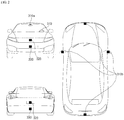
- FIG. 2 is a diagram showing exteriors of a vehicle according to an embodiment of the present invention, when viewed at various angles.
- FIGS. 3 and 4 are diagrams showing the interior of a vehicle according to an embodiment of the present invention.
- FIGS. 5 and 6 are diagrams referenced to describe an object according to an embodiment of the present invention.
- FIG. 7 is a block diagram referenced to describe a vehicle according to an embodiment of the present invention.
- a vehicle 100 may include wheels rotated by a power source, and a steering input unit 510 for controlling the direction of travel of the vehicle 100.
- the vehicle 100 may be an autonomous vehicle.
- the vehicle 100 may enter an autonomous mode or a manual mode based on user input.
- control mode of the vehicle 100 may be switched from the manual mode to the autonomous mode or from the autonomous mode to the manual mode based on user input received through a user interface device 200.
- the control mode of the vehicle 100 may be switched to the manual mode or the autonomous mode based on driving situation information.
- the driving situation information may include at least one of information on an object outside the vehicle, navigation information and vehicle state information.
- control mode of the vehicle 100 may be switched from the manual mode to the autonomous mode or from the autonomous mode to the manual mode based on driving situation information generated by an object detection device 300.
- control mode of the vehicle 100 may be switched from the manual mode to the autonomous mode or from the autonomous mode to the manual mode based on driving situation information received through a communication device 400.
- control mode of the vehicle 100 may be switched from the manual mode to the autonomous mode or from the autonomous mode to the manual mode based on information, and data signals provided by an external device.
- the autonomous vehicle 100 may operate based on an operation system 700.
- the autonomous vehicle 100 may operate based on information, data or signals generated by a driving system 710, a park-out system 740, and a park-in system 750.
- the autonomous vehicle 100 may receive user input for driving through a driving manipulation device 500.
- the vehicle 100 may be driven based on user input received through the driving manipulation device 500.
- an overall length refers to a length from the front side to the rear side of the vehicle 100
- an overall width refers to a width of the vehicle 100
- an overall height refers to a length from the bottom of a wheel to the roof of the vehicle 100.
- an overall length direction L may mean a direction based on which the overall length of the vehicle 100 is measured
- an overall width direction W may mean a direction based on which the overall width of the vehicle 100 is measured
- an overall height direction H may mean a direction based on which the overall height of the vehicle 100 is measured.
- the vehicle 100 may include a user interface (UI) device 200, the object detection device 300, the communication device 400, the driving manipulation device 500, the vehicle driving device 600, the operation system 700, the navigation system 770, the sensing unit 120, the interface unit 130, the memory 140, the controller 170, and a power supply 190.
- UI user interface
- the vehicle 100 may further include a new component in addition to the components described in the present invention, or may not include a part of the described components.
- the UI device 200 is a device used to enable the vehicle 100 to communicate with a user.
- the UI device 200 may receive a user input, and provide information generated from the vehicle 100 to the user.
- the vehicle 100 may implement UIs or User Experience (UX) through the UI device 200.
- UX User Experience
- the UI device 200 may include an input unit 210, an internal camera 220, a biometric sensing unit 230, an output unit 250, and a processor 270.
- the UI device 200 may further include a new component in addition to the above-described components, or may not include a part of the above-described components.
- the input unit 210 serves to receive a user command from a user. Data collected by the input unit 210 may be analyzed by the processor 270, and processed as a control command from the user.
- the input unit 210 may be disposed inside the vehicle 100.
- the input unit 210 may be disposed in an area of a steering wheel, an area of an instrument panel, an area of a seat, an area of each pillar, an area of a door, an area of a center console, an area of a head lining, an area of a sun visor, an area of a windshield, an area of a window, or the like.
- the input unit 210 may include a voice input unit 211, a gesture input unit 212, a touch input unit 213, and a mechanical input unit 214.
- the voice input unit 211 may convert voice input of the user into an electrical signal.
- the converted electrical signal may be provided to the processor 270 or the controller 170.
- the voice input unit 211 may include one or more microphones.
- the gesture input unit 212 may convert gesture input of the user into an electrical signal.
- the electrical signal may be provided to the processor 270 or the controller 170.
- the gesture input unit 212 may include at least one of an infrared (IR) sensor and an image sensor, for sensing gesture input of the user.
- IR infrared
- the gesture input unit 212 may sense a three-dimensional (3D) gesture input of the user.
- the gesture input unit 212 may include a light output unit for emitting a plurality of IR rays or a plurality of image sensors.
- the gesture input unit 212 may sense a 3D gesture input of the user by Time of Flight (ToF), structured light, or disparity.
- ToF Time of Flight
- structured light structured light
- disparity disparity
- the touch input unit 213 may convert touch input of the user to an electrical signal.
- the electrical signal may be provided to the processor 270 or the controller 170.
- the touch input unit 213 may include a touch sensor for sensing a touch input of the user.
- a touchscreen may be configured by integrating the touch input unit 213 with a display unit 251. This touchscreen may provide both an input interface and an output interface between the vehicle 100 and the user.
- the mechanical input unit 214 may include at least one of a button, a dome switch, a jog wheel, and a jog switch. An electrical signal generated by the mechanical input unit 214 may be provided to the processor 270 or the controller 170.
- the mechanical input unit 214 may be disposed on the steering wheel, a center fascia, the center console, a cockpit module, a door, or the like.
- the internal camera 220 may acquire a vehicle interior image.
- the processor 270 may sense a state of a user based on the vehicle interior image.
- the processor 270 may acquire gaze information of the user from the vehicle interior image.
- the processor 270 may determine a user gesture from the vehicle interior image.
- the biometric sensing unit 230 may acquire biometric information about a user.
- the biometric sensing unit 230 may include a sensor for acquiring biometric information about a user, and acquire information about a fingerprint and heart beats, and brain waves of a user, using the sensor.
- the biometric information may be used to authenticate the user.
- the output unit 250 is intended to generate a visual output, an acoustic output, or a haptic output.
- the output unit 250 may include at least one of the display unit 251, an audio output unit 252, and a haptic output unit 253.
- the display unit 251 may display graphic objects corresponding to various pieces of information.
- the display unit 251 may include at least one of a Liquid Crystal Display (LCD), a Thin-Film LCD (TF LCD), an Organic Light Emitting Diode (OLED) display, a flexible display, a 3D display, and an e-ink display.
- LCD Liquid Crystal Display
- TF LCD Thin-Film LCD
- OLED Organic Light Emitting Diode
- a touchscreen may be configured by forming a multilayered structure with the display unit 251 and the touch input unit 213 or integrating the display unit 251 with the touch input unit 213.
- the display unit 251 may be implemented by a Head Up Display (HUD). If the display unit 251 is implemented by a HUD, the display unit 251 may be provided with a projection module, and output information through an image projected onto the windshield or a window.
- HUD Head Up Display
- the display unit 251 may include a transparent display.
- the transparent display may be attached to the windshield or a window.
- the transparent display may have a specific transparency and display a specific screen.
- the transparent display may include at least one of a transparent Thin Film Electroluminescent (TFFL) display, a transparent OLED display, a transparent liquid crystal display (LCD), a transmissive transparent display, and a transparent LED display.
- TFFL Thin Film Electroluminescent
- OLED organic light-emitting diode
- LCD transparent liquid crystal display
- transmissive transparent display a transparent LED display.
- the transparency of the transparent display is controllable.
- the UI device 200 may include a plurality of display units 251a to 251g.
- the display unit 251 may be disposed in an area of the steering wheel, areas 251a, 251b and 251e of the instrument panel, an area 251d of a seat, an area 251 f of each pillar, an area 251g of a door, an area of the center console, an area of a head lining, or an area of a sun visor, or may be implemented in an area 251c of the windshield, and an area 251h of a window.
- the audio output unit 252 converts an electrical signal received from the processor 270 or the controller 170 into an audio signal, and outputs the audio signal.
- the audio output unit 252 may include one or more speakers.
- the haptic output unit 253 generates a haptic output.
- the haptic output unit 253 may vibrate the steering wheel, a safety belt, a seat 110FL, 110FR, 110RL, or 110RR, so that a user may perceive the output.
- the processor 270 may provide overall control to each unit of the UI device 200.
- the UI device 200 may include a plurality of processor 270 or no processor 270.
- the UI device 200 may operate under the control of a processor of another device in the vehicle 100, or under the control of the controller 170.
- the UI device 200 may be referred to as a vehicle display device.
- the UI device 200 may operate under the control of the controller 170.
- the object detection device 300 is a device used to detect an object located outside the vehicle 100.
- the object detection device 300 may generate object information based on sensing data.
- the object information may include information on presence/absence of an object, location information of the object, information on a distance between the vehicle 100 and the object and relative speed information of the object to the vehicle 100.
- the object may be any of various items related to driving of the vehicle 100.
- objects O may include lines OB10, another vehicle OB11, a pedestrian OB12, a 2-wheel vehicle OB13, traffic signals OB14 and OB15, light, a road, a structure, a speed bump, topography, an animal, and so on.
- the lanes OB10 may include a driving lane, a lane next to the driving lane, and a lane in which an oncoming vehicle is driving.
- the lanes OB 10 may conceptually include left and right lines that define each of the lanes.
- the lanes may conceptually include crossroads.
- the other vehicle OB11 may be a vehicle driving in the vicinity of the vehicle 100.
- the other vehicle OB 11 may be located within a predetermined distance from the vehicle 100.
- the other vehicle OB11 may precede or follow the vehicle 100.
- the pedestrian OB12 may be a person located around the vehicle 100.
- the pedestrian OB12 may be a person located within a predetermined distance from the vehicle 100.
- the pedestrian OB 12 may be a person on a sidewalk or a roadway.
- the 2-wheel vehicle OB 13 may refer to a transportation means moving on two wheels, located around the vehicle 100.
- the 2-wheel vehicle OB13 may be a transportation means having two wheels, located within a predetermined distance from the vehicle 100.
- the 2-wheel vehicle OB13 may be a motorbike or bicycle on a sidewalk or a roadway.
- the traffic signals OB14 and OB15 may include a traffic signal lamp OB15, a traffic sign OB14, and a symbol or text drawn or written on a road surface.
- the light may be light generated from a lamp of the other vehicle OB11.
- the light may be generated from a street lamp.
- the light may be sunlight.
- the road may include a road surface, a curve, a slope such as a downhill road or an uphill road, and so on.
- the structure may be an object fixed to the ground, near a road.
- the structure may be any of a street lamp, a street tree, a building, a telephone pole, a signal lamp, a bridge, a curbstone, and a guard rail.
- the topography may include a mountain, a hill, and so on.
- Objects may be classified into mobile objects and fixed objects.
- the mobile object may conceptually include another vehicle and a pedestrian.
- the fixed object may conceptually include a traffic signal, a road, a structure, a stopped another vehicle and a stopped pedestrian.
- the object detection device 300 may include the camera 310, a Radio Detection and Ranging (RADAR) 320, a Light Detection and Ranging (LiDAR) 330, an ultrasonic sensor 340, an IR sensor 350, and a processor 370.
- RADAR Radio Detection and Ranging
- LiDAR Light Detection and Ranging
- the object detection device 300 may further include a new component in addition to the above-described components or may not include a part of the above-described components.
- the camera 310 may be disposed at an appropriate position on the exterior of the vehicle 100.
- the camera 310 may be a mono camera, a stereo camera 310a, an Around View Monitoring (AVM) camera 310b, or a 360-degree camera.
- AVM Around View Monitoring
- the camera 310 may acquire location information of an object, information on a distance to the object or information on a relative speed of the object using various image processing algorithms.
- the camera 310 may acquire the information on the distance and relative speed of the object based on change in size of the object according to the lapse of time from the acquired image.
- the camera 310 may acquire the information on the distance and relative speed of the object through pinhole model and road surface profiling.
- the camera 310 may acquire the information on the distance and relative speed of the object based on disparity information from a stereo image acquired by the stereo camera 310a.
- the camera 310 may be disposed in the vicinity of a front windshield inside the vehicle 100.
- the camera 310 may be disposed around a front bumper or a radiator grill.
- the camera 310 may be disposed in the vicinity of a rear glass inside the vehicle 100.
- the camera 310 may be disposed around a rear bumper, a trunk, or a tailgate.
- the camera 310 may be disposed in the vicinity of at least one of side windows inside the vehicle 100.
- the camera 310 may be disposed around a side-view mirror, a fender, or a door.
- the camera 310 may provide the acquired image to the processor 370.
- the RADAR 320 may include an electromagnetic wave transmitter and an electromagnetic wave receiver.
- the RADAR 320 may be implemented by pulse RADAR or continuous wave RADAR.
- the RADAR 320 may be implemented by Frequency Modulated Continuous Wave (FMCW) or Frequency-Shift Keying (FSK) as a continuous-wave RADAR scheme according to a signal waveform.
- FMCW Frequency Modulated Continuous Wave
- FSK Frequency-Shift Keying
- the RADAR 320 may detect an object by electromagnetic waves based on a TOF or phase-shift method, and determine a location, distance, and relative speed of the detected object.
- the RADAR 320 may be disposed at an appropriate position on the exterior of the vehicle in order to sense an object ahead of, behind, or beside the vehicle 100.
- the LiDAR 330 may include a laser transmitter and a laser receiver.
- the LiDAR 330 may be implemented using a TOF or phase-shift method.
- the LiDAR 330 may be implemented in a driven or non-driven manner.
- the LiDAR 330 may be rotated by a motor and detect an object around the vehicle 100.
- the LiDAR 330 may detect an object within a predetermined range from the vehicle 100 by optical steering.
- the vehicle 100 may include a plurality of non-driven LiDARs 330.
- the LiDAR 330 may detect an object by laser light based on a TOF or phase-shift method, and determine a location, distance, and relative speed of the detected object.
- the LiDAR 330 may be disposed at an appropriate position on the exterior of the vehicle 100 in order to sense an object ahead of, behind, or beside the vehicle 100.
- the ultrasonic sensor 340 may include an ultrasonic wave transmitter and an ultrasonic wave receiver.
- the ultrasonic sensor 340 may detect an object by ultrasonic waves, and determine a location, distance, and relative speed of the detected object.
- the ultrasonic sensor 340 may be disposed at an appropriate position on the exterior of the vehicle 100 in order to sense an object ahead of, behind, or beside the vehicle 100.
- the IR sensor 350 may include an IR transmitter and an IR receiver.
- the IR sensor 350 may detect an object using IR light, and determine a location, distance, and relative speed of the detected object.
- the IR sensor 350 may be disposed at an appropriate position on the exterior of the vehicle 100 in order to sense an object ahead of, behind, or beside the vehicle 100.
- the processor 370 may provide overall control to each unit of the object detection device 300.
- the processor 370 may compare data sensed by the camera 310, the RADAR 320, the LiDAR 330, the ultrasonic sensor 340 and the IR sensor 350 with prestored data, thereby detecting or classifying objects.
- the processor 370 may detect an object and track the detected object, based on an acquired image.
- the processor 370 may perform operations including calculation of a distance to the object, and calculation of a relative speed of the object, using an image processing algorithm.
- the processor 370 may acquire the information on the distance and relative speed of the object based on change in size of the object according to the lapse of time from the acquired image.
- the processor 370 may acquire the information on the distance and relative speed of the object through pinhole model and road surface profiling.
- the processor 370 may acquire the information on the distance and relative speed of the object based on disparity information from a stereo image acquired by the stereo camera 310a.
- the processor 370 may detect an object and track the detected object based on electromagnetic waves which are transmitted, are reflected from an object, and then return.
- the processor 370 may perform operations including calculation of a distance to the object and a relative speed of the object, based on the electromagnetic waves.
- the processor 370 may detect an object and track the detected object based on laser light which is transmitted, is reflected from an object, and then returns.
- the processor 370 may perform operations including calculation of a distance to the object and a relative speed with respect to the object, based on the laser light.
- the processor 370 may detect an object and track the detected object based on ultrasonic waves which are transmitted, are reflected from an object, and then return.
- the processor 370 may perform operations including calculation of a distance to the object and a relative speed with respect to the object based on the ultrasonic waves.
- the processor 370 may detect an object and track the detected object based on IR light which is transmitted, is reflected from an object, and then returns.
- the processor 370 may perform operations including calculation of a distance to the object and a relative speed with respect to the object based on the IR light.
- the object detection device 300 may include a plurality of sensing processors 370 or no processor 370.
- each of the camera 310, the RADAR 320, the LiDAR 330, the ultrasonic sensor 340, and the IR sensor 350 may include a processor individually.
- the object detection device 300 may operate under the control of a processor of a device in the vehicle 100 or under the control of the controller 170.
- the object detection device 300 may operate under the control of the controller 170.
- the communication device 400 is used to communicate with an external device.
- the external device may be one of another vehicle, a mobile terminal, and a server.
- the communication device 400 may include at least one of a transmission antenna and a reception antenna, for communication, and a Radio Frequency (RF) circuit and device, for implementing various communication protocols.
- RF Radio Frequency
- the communication device 400 may include a short-range communication unit 410, a location information unit 420, a V2X communication unit 430, an optical communication unit 440, a broadcast transceiver unit 450, an Intelligent Transport System (ITS) communication unit 460, and a processor 470.
- a short-range communication unit 410 may include a short-range communication unit 410, a location information unit 420, a V2X communication unit 430, an optical communication unit 440, a broadcast transceiver unit 450, an Intelligent Transport System (ITS) communication unit 460, and a processor 470.
- ITS Intelligent Transport System
- the communication device 400 may further include a new component in addition to the above-described components, or may not include a part of the above-described components.
- the short-range communication module 410 may support short-range communication, using at least one of BluetoothTM, Radio Frequency Identification (RFID), Infrared Data Association (IrDA), Ultra-Wideband (UWB), ZigBee, Near Field Communication (NFC), Wireless Fidelity (Wi-Fi), Wi-Fi Direct, and Wireless Universal Serial Bus (Wireless USB).
- RFID Radio Frequency Identification
- IrDA Infrared Data Association
- UWB Ultra-Wideband
- ZigBee Near Field Communication
- NFC Near Field Communication
- Wi-Fi Wireless Fidelity
- Wi-Fi Direct Wireless Universal Serial Bus
- the short-range communication unit 410 may conduct short-range communication between the vehicle 100 and at least one external device by establishing a wireless area network.
- the location information unit 420 is a unit configured to acquire information about a location of the vehicle 100.
- the location information unit 420 may include a Global Positioning System (GPS) module or a Differential Global Positioning System (DGPS) module.
- GPS Global Positioning System
- DGPS Differential Global Positioning System
- the V2X communication unit 430 is a unit used for wireless communication with a server (by Vehicle to Infrastructure (V2I)), another vehicle (by Vehicle to Vehicle (V2V)), or a pedestrian (by Vehicle to Pedestrian (V2P)).
- the V2X communication unit 430 may include an RF circuit capable of implementing a V2I protocol, a V2V protocol, and a V2P protocol.
- the optical communication unit 440 is a unit used to communicate with an external device by light.
- the optical communication unit 440 may include an optical transmitter for converting an electrical signal into an optical signal and radiating the optical signal to the outside, and an optical receiver for converting a received optical signal into an electrical signal.
- the optical transmitter may be integrated with a lamp included in the vehicle 100.
- the broadcast transceiver unit 450 is a unit used to receive a broadcast signal from an external broadcast management server or transmit a broadcast signal to the broadcast management server, through a broadcast channel.
- the broadcast channel may include a satellite channel and a terrestrial channel.
- the broadcast signal may include a TV broadcast signal, a radio broadcast signal, and a data broadcast signal.
- the ITS communication unit 460 may exchange information, data or signals with a traffic system.
- the ITS communication unit 460 may provide acquired information and data to the traffic system.
- the ITS communication unit 460 may receive information, data or signals from the traffic system.
- the ITS communication unit 460 may receive road traffic information from the traffic system and provide the road traffic information to the controller 170.
- the ITS communication unit 460 may receive a control signal from the traffic system and provide the control signal to the controller 170 or the processor provided in the vehicle 100.
- the processor 470 may provide overall control to each unit of the communication device 400.
- the communication device 400 may include a plurality of communication processors 470 or no processor 470.
- the communication device 400 may operate under the control of a processor of another device in the vehicle 100 or under the control of the controller 170.
- the communication device 400 may be configured as a vehicle display device, together with the UI device 200.
- the vehicle display device may be referred to as a telematics device or an Audio Video Navigation (AVN) device.
- APN Audio Video Navigation
- the communication device 400 may operate under the control of the controller 170.
- the driving manipulation device 500 is a device used to receive a user command for driving the vehicle 100.
- the vehicle 100 may be driven based on a signal provided by the driving manipulation device 500.
- the driving manipulation device 500 may include the steering input device 510, an acceleration input device 530, and a brake input device 570.
- the steering input device 510 may receive a user command for steering the vehicle 100 from a user.
- the steering input device 510 is preferably configured as a wheel for enabling steering input by rotation thereof.
- the steering input device 510 may be configured as a touchscreen, a touchpad, or a button.
- the acceleration input device 530 may receive a user command input for acceleration of the vehicle 100 from the user.
- the brake input device 570 may receive a user command for deceleration of the vehicle 100 from the user.
- the acceleration input device 530 and the brake input device 570 may be formed into pedals.
- the acceleration input device or the brake input device may be configured as a touchscreen, a touchpad, or a button.
- the driving manipulation device 500 may operate under the control of the controller 170.
- the vehicle driving device 600 is a device used to electrically control driving of various devices of the vehicle 100.
- the vehicle driving device 600 may include at least one of a powertrain driving unit 610, a chassis driving unit 620, a door/window driving unit 630, a safety apparatus driving unit 640, a lamp driving unit 650, and an air conditioner driving unit 660.
- the vehicle driving device 600 may further include a new component in addition to the above-described components or may not include a part of the above-described components.
- the vehicle driving device 600 may include a processor. Each individual unit of the vehicle driving device 600 may include a processor.
- the powertrain driving unit 610 may control operation of a powertrain device.
- the powertrain driving unit 610 may include a power source driver 611 and a transmission driver 612.
- the power source driver 611 may control a power source of the vehicle 100.
- the power source driver 610 may perform electronic control of the engine. Therefore, the power source driver 610 may control an output torque of the engine, and the like.
- the power source driver 611 may adjust the engine output torque under the control of the controller 170.
- the power source driver 610 may control the motor.
- the power source driver 610 may adjust a rotation speed, torque, and so on of the motor under the control of the controller 170.
- the transmission driver 612 may control a transmission.
- the transmission driver 612 may adjust a state of the transmission.
- the transmission driver 612 may adjust the state of the transmission to drive D, reverse R, neutral N, or park P.
- the transmission driver 612 may adjust an engagement state of a gear in the drive state D.
- the chassis driving unit 620 may control operation of a chassis device.
- the chassis driving unit 620 may include a steering driver 621, a brake driver 622, and a suspension driver 623.
- the steering driver 621 may perform electronic control of a steering apparatus in the vehicle 100.
- the steering driver 621 may change a driving direction of the vehicle 100.
- the brake driver 622 may perform electronic control of a brake apparatus in the vehicle 100. For example, the brake driver 622 may decrease the speed of the vehicle 100 by controlling an operation of a brake disposed at a tire.
- the brake driver 622 may control a plurality of brakes individually.
- the brake driver 622 may differentiate braking power applied to a plurality of wheels.
- the suspension driver 623 may perform electronic control of a suspension device in the vehicle 100. For example, if the surface of a road is rough, the suspension driver 623 may control the suspension device to reduce vibration of the vehicle 100 when a road has an uneven surface.
- the suspension driver 623 may control a plurality of suspensions individually.
- the door/window driving unit 630 may perform electronic control of a door apparatus or a window apparatus in the vehicle 100.
- the door/window driving unit 630 may include a door driver 631 and a window driver 632.
- the door driver 631 may perform electronic control of a door apparatus in the vehicle 100.
- the door driver 631 may control opening and closing of a plurality of doors in the vehicle 100.
- the door driver 631 may control opening or closing of the trunk or the tailgate.
- the door driver 631 may control opening or closing of the sunroof.
- the window driver 632 may perform electronic control of a window apparatus in the vehicle 100.
- the window driver 632 may control opening or closing of a plurality of windows in the vehicle 100.
- the safety apparatus driving unit 640 may perform electronic control of various safety apparatuses in the vehicle 100.
- the safety apparatus driving unit 640 may include an airbag driver 641, a seatbelt driver 642, and a pedestrian protection device driver 643.
- the airbag driver 641 may perform electronic control of an airbag apparatus in the vehicle 100.
- the airbag driver 641 may control inflation of an airbag, upon sensing an emergency situation.
- the seatbelt driver 642 may perform electronic control of a seatbelt apparatus in the vehicle 100.
- the seatbelt driver 642 may control securing of passengers on the seats 110FL, 110FR, 110RL, and 110RR by means of seatbelts, upon sensing danger.
- the pedestrian protection device driver 643 may perform electronic control of a hood lift and a pedestrian airbag in the vehicle 100.
- the pedestrian protection device driver 643 may control hood lift-up and inflation of the pedestrian airbag, upon sensing collision with a pedestrian.
- the lamp driving unit 650 may perform electronic control of various lamp apparatuses in the vehicle 100.
- the air conditioner driver 660 may perform electronic control of an air conditioner in the vehicle 100. For example, if a vehicle internal temperature is high, the air conditioner driver 660 may control the air conditioner to operate and supply cool air into the vehicle 100.
- the vehicle driving device 600 may include a processor. Each individual unit of the vehicle driving device 600 may include a processor.
- the vehicle driving device 600 may operate under the control of the controller 170.
- the operation system 700 is a system that controls various operations of the vehicle 100.
- the operation system 700 may operate in the autonomous mode.
- the operation system 700 may include a driving system 710, a park-out system 740, and a park-in system 750.
- the operation system 700 may further include a new component in addition to the above-described components or may not include a part of the above-described components.
- the operation system 700 may include a processor.
- Each individual unit of the operation system 700 may include a processor.
- the operation system 700 may have the subordinate concept of the controller 170.
- the operation system 700 may conceptually include at least one of the UI device 200, the object detection device 300, the communication device 400, the driving manipulation device 500, the vehicle driving device 600, and the controller 170.
- the driving system 710 may control autonomous driving of the vehicle 100.
- the driving system 710 may receive navigation information from the navigation system 770 and provide a control signal to the vehicle driving device 600, thereby driving the vehicle 100.
- the driving system 710 may receive object information from the object detection device 300 and provide a control signal to the vehicle driving device 600, thereby driving the vehicle 100.
- the driving system 710 may receive a signal from an external device through the communication device 400 and provide a control signal to the vehicle driving device 600, thereby driving the vehicle 100.
- the driving system 710 may include at least one of the UI device 200, the object detection device 300, the communication device 400, the driving manipulation device 500, the vehicle driving device 600, the navigation system 770, the sensing unit 120 and the controller 170 to drive the vehicle 100.
- the driving system 710 may also be referred to as a vehicle driving control device.
- the park-out system 740 may control automatic park-out of the vehicle 100.
- the park-out system 740 may receive navigation information from the navigation system 770 and provide a control signal to the vehicle driving device 600, so that the vehicle 100 may leave.
- the park-out system 740 may receive object information from the object detection device 300 and provide a control signal to the vehicle driving device 600, so that the vehicle 100 may leave.
- the park-out system 740 may receive a signal from an external device through the communication device 400 and provide a control signal to the vehicle driving device 600, so that the vehicle 100 may leave.
- the park-out system 740 may include at least one of the UI device 200, the object detection device 300, the communication device 400, the driving manipulation device 500, the vehicle driving device 600, the navigation system 770, the sensing unit 120 and the controller 170, so that the vehicle 100 may leave.
- the park-out system 740 may also be referred to as a vehicle part-out control device.
- the park-in system 750 may control automatic park-in of the vehicle 100.
- the park-in system 750 may receive navigation information from the navigation system 770 and provide a control signal to the vehicle driving device 600, so that the vehicle 100 may park.
- the park-in system 750 may receive a signal from an external device through the communication device 400 and provide a control signal to the vehicle driving device 600, so that the vehicle 100 may park.
- the park-in system 750 may receive object information from the object detection device 300 and provide a control signal to the vehicle driving device 600, so that the vehicle 100 may park.
- the park-in system 750 may include at least one of the UI device 200, the object detection device 300, the communication device 400, the driving manipulation device 500, the vehicle driving device 600, the navigation system 770, the sensing unit 120 and the controller 170, so that the vehicle 100 may park.
- the park-in system 750 may also be referred to as a vehicle park-in control device.
- the navigation system 770 may provide navigation information.
- the navigation information may include at least one of map information, set destination information, path information, information about various objects on a road, lane information, and information about a location of a vehicle.
- the navigation system 770 may include a memory and a processor.
- the memory may store navigation information.
- the processor may control operation of the navigation system 770.
- the navigation system 770 may receive information from an external device through the communication device 400 and update pre-stored information using the received information.
- the navigation system 770 may be classified as a lower-layer component of the UI device 200.
- the sensing unit 120 may sense a state of the vehicle 100.
- the sensing unit 120 may include an inertial navigation unit (IMU) sensor, a collision sensor, a wheel sensor, a speed sensor, an inclination sensor, a weight sensor, a heading sensor, a position module, a vehicle forward/backward sensor, a battery sensor, a fuel sensor, a tire sensor, a handle rotation-based steering sensor, a vehicle internal temperature sensor, a vehicle internal humidity sensor, an ultrasonic sensor, an illumination sensor, an accelerator pedal position sensor, a brake pedal position sensor, and so on.
- IMU inertial navigation unit
- an inertial navigation unit (IMU) sensor may include one or more of an acceleration sensor, a gyro sensor and a magnetic sensor.
- the sensing unit 120 may acquire sensing signals for vehicle posture information, vehicle motion information, vehicle collision information, vehicle heading information, vehicle location information (GPS information), vehicle angle information, vehicle speed information, vehicle acceleration information, vehicle inclination information, vehicle forward/backward information, battery information, fuel information, tire information, vehicle lamp information, vehicle internal temperature information, vehicle internal humidity information, a steering wheel rotation angle, a vehicle external illuminance, a pressure applied to an accelerator pedal, a pressure applied to a brake pedal, and so on.
- GPS information vehicle location information
- vehicle angle information vehicle speed information
- vehicle acceleration information vehicle acceleration information
- vehicle inclination information vehicle forward/backward information
- battery information fuel information, tire information, vehicle lamp information, vehicle internal temperature information, vehicle internal humidity information, a steering wheel rotation angle, a vehicle external illuminance, a pressure applied to an accelerator pedal, a pressure applied to a brake pedal, and so on.
- the sensing unit 120 may further include an accelerator pedal sensor, a pressure sensor, an engine speed sensor, an Air Flow Sensor (AFS), an Air Temperature Sensor (ATS), a Water Temperature Sensor (WTS), a Throttle Position Sensor (TPS), a Top Dead Center (TDC) sensor, a Crank Angle Sensor (CAS), and so on.
- AFS Air Flow Sensor
- ATS Air Temperature Sensor
- WTS Water Temperature Sensor
- TPS Throttle Position Sensor
- TDC Top Dead Center
- CAS Crank Angle Sensor
- the sensing unit 120 may generate vehicle state information based on sensing data.
- the vehicle state information may be generated based on data sensed by various types of sensors provided in the vehicle.
- the vehicle state information may include vehicle posture information, vehicle speed information, vehicle inclination information, vehicle weight information, vehicle direction information, vehicle battery information, vehicle fuel information, vehicle tire pressure information, vehicle steering information, vehicle interior temperature information, vehicle interior humidity information, pedal position information and vehicle engine temperature information.
- the interface unit 130 serves as paths to various types of external devices connected to the vehicle 100.
- the interface unit 130 may be provided with a port connectable to a mobile terminal, and may be connected to a mobile terminal through the port.
- the interface unit 130 may exchange data with the mobile terminal.
- the interface unit 130 may serve as a path in which electric energy is supplied to a connected mobile terminal. If the mobile terminal is electrically connected to the interface unit 130, the interface unit 130 may supply electric energy received from the power supply 190 to the mobile terminal under the control of the controller 170.
- the memory 140 is electrically connected to the controller 170.
- the memory 140 may store basic data of a unit, control data for controlling an operation of the unit, and input and output data.
- the memory 140 may be any of various storage devices in hardware, such as Read Only Memory (ROM), Random Access Memory (RAM), Erasable and Programmable ROM (EPROM), flash drive, and hard drive.
- ROM Read Only Memory
- RAM Random Access Memory
- EPROM Erasable and Programmable ROM
- flash drive and hard drive.
- the memory 140 may store a variety of data for overall operations of the vehicle 100, such as programs for processing or controlling in the controller 170.
- the memory 140 may be integrated with the controller 170, or configured as a lower-layer component of the controller 170.
- the controller 170 may provide overall control to each unit inside the vehicle 100.
- the controller 170 may be referred to as an Electronic Control Unit (ECU).
- ECU Electronic Control Unit
- the power supply 190 may supply power needed for operating each component under the control of the controller 170. Particularly, the power supply 190 may receive power from a battery within the vehicle 100.
- One or more processors and the controller 170 of the vehicle 100 may be implemented in hardware using at least one of Application Specific Integrated Circuits (ASICs), Digital Signal Processors (DSPs), Digital Signal Processing Device (DSPDs), Programmable Logic Devices (PLDs), Field Programmable Gate Arrays (FPGAs), processors, controllers, microcontrollers, microprocessors, and an electrical unit for executing other functions.
- ASICs Application Specific Integrated Circuits
- DSPs Digital Signal Processors
- DSPDs Digital Signal Processing Device
- PLDs Programmable Logic Devices
- FPGAs Field Programmable Gate Arrays
- processors controllers, microcontrollers, microprocessors, and an electrical unit for executing other functions.
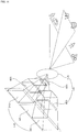
- FIG. 8a is a diagram referenced to describe a plurality of cameras included in an around view monitoring apparatus for a vehicle according to an embodiment of the present invention.
- the around view monitoring apparatus 800 for the vehicle may include a plurality of cameras 810.
- the around view monitoring apparatus 800 for the vehicle includes four cameras 810a, 810b, 810c, 810d.
- the around view monitoring apparatus 800 for the vehicle may include less than four cameras or more than four cameras.
- the plurality of cameras 810a, 810b, 810c and 810d may be attached to at least one of a moving part and a fixed part of the vehicle.
- the moving part of the vehicle refers to a movable part among parts of the vehicle forming the appearance and frame of the vehicle.
- the moving part of the vehicle may include a side-view mirror, a door, a sunroof, a wiper, a bonnet (or hood), a wheel and a window.
- the fixed part of the vehicle refers to a non-movable part among parts of the vehicle forming the appearance and frame of the vehicle.
- the fixed part of the vehicle may include a bumper, a grill, a fender, a wheelhouse, a roof and a windshield.
- the plurality of cameras 810 may include a front camera 810a, a rear camera 810b, a left camera 810c and a right camera 810d.
- the front camera 810a may acquire a front image of the vehicle 100.
- the front camera 810a may be attached to a front bumper as a fixed part.
- the front camera 810a may be provided inside the grill.
- the rear camera 810b may acquire a rear image of the vehicle 100.
- the rear camera 810b may be attached to a back door as a moving part.
- the back door may include a trunk and a tailgate.
- the rear camera 810b may be attached to a rear bumper as a fixed part.
- the left camera 810c may acquire a left image of the vehicle 100.
- the left camera 810c may be attached to a left side-view mirror as a moving part.
- the left side-view mirror may include a mirror, various electric parts, a case surrounding the mirror and the electric parts, etc.
- the left side-view mirror may be referred to as a left side-view mirror module.
- the left camera 810c may be attached to a left front door as a moving part.
- the left front door may include a left side-view mirror.
- the right camera 810d may acquire a right image of the vehicle.
- the right camera 810d may be attached to a right side-view mirror as a moving part.
- the right side-view mirror may include a mirror, various electric parts, a case surrounding the mirror and the electric parts, etc.
- the right side-view mirror may be referred to as a right side-view mirror module.
- the right camera 810d may be attached to a right front door as a moving part.
- the right front door may include a right side-view mirror.
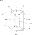
- FIG. 8b is a diagram showing an embodiment of an around view image generated by an around view monitoring apparatus for a vehicle according to an embodiment of the present invention.
- the around view monitoring apparatus 800 for the vehicle may generate an around view image 801.
- the processor 870 of the around view monitoring apparatus 800 for the vehicle may combine a plurality of images acquired by the plurality of cameras 810 to generate the around view image 801.
- the processor 870 of the around view monitoring apparatus 800 for the vehicle may combine a front image acquired by the front camera 810a, a rear image acquired by the rear camera 810b, a left image acquired by the left camera 810c, and a right image acquired by the right camera 810d to generate the around view image 801.
- the around view image 801 may include at least one of a top-view image, a side-view image, a front-view image, and a rear-view image.
- the around view image 801 may be implemented by a 2D image or a 3D image.
- the around view image 801 may include a border line BL.
- the border line BL may refer to a line for dividing regions corresponding to the plurality of images acquired by the plurality of cameras 810 in the around view image 801.
- the around view image 801 may include a first region 810ai, a second region 810bi, a third region 810ci and a fourth region 810di.
- the first region 811i may correspond to the front image.
- the second region 812i may correspond to the rear image.
- the third region 813i may correspond to the left image.
- the fourth region 814i may correspond to the right image.
- the around view image 801 may include a vehicle image 100i corresponding to the vehicle 100.
- FIG. 9 is a block diagram referenced to describe an around view monitoring apparatus for a vehicle according to an embodiment of the present invention.
- the around view monitoring apparatus 800 for the vehicle may include the plurality of cameras 810, a memory 840, a display unit 851, a processor 870 and a power supply unit 890.
- the around view monitoring apparatus 800 for the vehicle may further include an auxiliary camera 820, a camera posture adjuster 830, a sound output unit 852 or a combination thereof.
- the plurality of cameras 810 may be attached to the vehicle 100.
- the plurality of cameras 810 may be attached to at least one of the moving part and the fixed part of the vehicle.
- Each of the plurality of cameras 810 may include a lens unit and an image sensor.
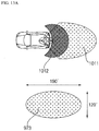
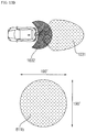
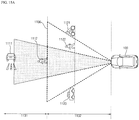
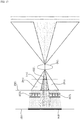
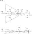
- One or more of the plurality of cameras 810 may include a lens unit for enabling focal lengths of two or more regions included in the acquired image to be different from each other.
- An image acquired by any one of the plurality of cameras 810 may include a first region having a relatively narrow angle and a second region having a relative wide angle.
- Each of the plurality of cameras 810 may include an image sensor.
- One or more of the plurality of cameras 810 may include an image sensor including two or more pixel arrays formed to correspond to two or more regions.
- the image sensor may convert light input to the two or more pixel arrays through the lens unit into an electrical signal.
- the two or more pixel arrays may have different pixel densities.
- the camera posture adjuster 830 may control the posture of each of the plurality of cameras 810.
- the camera posture adjuster 830 may include a plurality of drive units corresponding in number to the plurality of cameras 810.
- the drive unit may include a driving power generation unit such as a motor, an actuator or a solenoid.
- the camera posture adjuster 830 may include a first drive unit corresponding to the left camera 810c, a second drive unit corresponding to the right camera 810d, a third drive unit corresponding to the rear camera 810b, and a fourth drive unit corresponding to the front camera 810a.
- the camera posture adjuster 830 may adjust the posture of the camera attached to the moving part based on motion information of the moving part, under control of the processor 870.
- the memory 840 is electrically connected to the processor 870.
- the memory 840 may store basic data for a unit, control data for operation control of the unit, and input/output data.
- the memory 840 may be various hardware storage devices such as a ROM, a RAM, an EPROM, a flash drive and a hard drive.
- the memory 840 may store a variety of data for overall operation of the around view monitoring apparatus 800 for the vehicle, such as programs for processing or control of the processor 870.
- the memory 840 may be integrated with the processor 870, or configured as a lower-layer component of the processor 870.
- the display unit 851 may display the around view image under control of the processor 870.
- the display unit 851 may be integrated with the display unit 251 of the UI device 200.
- the display unit 851 may be referred to as an AVN (Audio Video Navigation) device, a CID (Center Information Display), a head unit, etc.
- AVN Audio Video Navigation
- CID Center Information Display
- the display unit 851 may be combined with the communication unit 400 and thus may be implemented as a telematics device.
- the sound output unit 852 may output an audio signal under control of the processor 870.
- the sound output unit 852 may be integrated with the audio output unit 252 of the UI device 200.
- the display unit 851 and the sound output unit 852 may be configured as lower-layer components of the output unit of the around view monitoring apparatus for the vehicle.
- the processor 870 may be electrically connected to the units of the around view monitoring apparatus 800 for the vehicle.
- the processor 870 may control overall operation of the units of the around view monitoring apparatus 800 for the vehicle.
- the processor 870 may be implemented in hardware using at least one of Application Specific Integrated Circuits (ASICs), Digital Signal Processors (DSPs), Digital Signal Processing Devices (DSPDs), Programmable Logic Device (PLDs), Field Programmable Gate Arrays (FPGAs), processors, controllers, microcontrollers, microprocessors, and an electrical unit for executing other functions.
- ASICs Application Specific Integrated Circuits
- DSPs Digital Signal Processors
- DSPDs Digital Signal Processing Devices
- PLDs Programmable Logic Device
- FPGAs Field Programmable Gate Arrays
- processors controllers, microcontrollers, microprocessors, and an electrical unit for executing other functions.
- the processor 870 may receive the images from the plurality of cameras 810.
- the processor 870 may receive the front image from the front camera 810a.
- the processor 870 may receive the rear image from the rear camera 810b.
- the processor 870 may receive the left image from the left camera 810c.
- the processor 870 may receive the right image from the right camera 810c.
- the processor 870 may process the plurality of images acquired by the plurality of cameras 810.
- the processor 870 may combine the plurality of images acquired by the plurality of cameras 810 to generate the around view image.
- the around view image may include at least one of a top-view image, a side-view image, a front-view image, and a rear-view image.
- the image received from at least one of the plurality of cameras 810 may include a first region having a relatively narrow angle and a second region having a relative wide angle.
- the processor 870 may divide and process the first region and the second region.
- the processor 870 may generate a narrow-angle image based on the first image.
- the processor 870 may synthesize the first region and the second region based on a mapping function to generate a wide-angle image.
- the processor 870 may provide the narrow-angle image and the wide-angle image to one or more devices inside the vehicle through the interface 880.
- the processor 870 may alternately provide the narrow-angle image and the wide-angle image to other devices inside the vehicle through one cable.
- the processor 870 may alternately provide the narrow-angle image and the wide-angle image to a device in frame or slice units.
- the slice may be defined as a unit region divided from a full image based on a predetermined criterion.
- the processor 870 may transmit a first frame of the narrow-angle image in a first time range.
- the processor 870 may transmit a first frame of the wide-angle image in a second time range.
- the processor 870 may transmit a second frame of the narrow-angle image in a third time range.
- the processor 870 may transmit a second frame of the wide-angle image in a fourth time range. Thereafter, the processor 870 may alternately transmit the narrow-angle image and the wide-angle image in frame units.
- the processor 870 may transmit a first slice of the narrow-angle image in a first time range.
- the processor 870 may transmit a first slice of the wide-angle image in a second time range.
- the processor 870 may transmit a second slice of the narrow-angle image in a third time range. Thereafter, the processor 870 may alternately transmit the narrow-angle image and the wide-angle image in slice units.
- the processor 870 may transmit the narrow-angle image and the wide-angle image to other devices inside the vehicle using two cables.
- the processor 870 may provide the narrow-angle image through a first port of the interface 880.
- the processor 870 may transmit the narrow-angle image through the first port in frame units or slice units.
- the processor 870 may provide the wide-angle image through a second port of the interface 880.
- the processor 870 may transmit the wide-angle image through the second port in frame units or slice units.
- the processor 870 may control the display unit 851 to display the image based on the narrow-angle image and the wide-angle image.
- the processor 870 may control the display unit 851 to display the around view image based on the plurality of the wide-angle images.
- the processor 870 may control the display unit 851 to display an e-mirror image based on the rear narrow-angle image.
- the e-mirror image may be an image viewed through a rear-view mirror or a side-view mirror to enable a user to recognize a rear state of the vehicle.
- the e-mirror image may be generated based on the image acquired by the rear camera 810b.
- the e-mirror image may be generated based on the images acquired by the left camera 810c and the right camera 810d.
- the processor 870 may detect an object based on the narrow-angle image.
- the processor 870 may generate information on the object based on the narrow-angle image.
- the processor 870 may provide the information on the object to another device.
- the processor 870 may detect the object based on the wide-angle image.
- the processor 870 may generate the information on the object based on the wide-angle image.
- the processor 870 may provide the information on the object to another device.
- the interface 880 may exchange information, signals or data with one or more devices included in the vehicle 100.
- the devices included in the vehicle 100 may include the UI device 200, the object detection device 300, the communication unit 400, the driving manipulation device 500, the vehicle driving device 600, the operation system 700, the navigation system 770, the sensing unit 120, the memory 140, the controller 170, and the power supply unit 190.
- the interface 880 may receive information, signals and data from another device included in the vehicle 100.
- the interface 880 may transmit the received information, signals or data to the processor 870.
- the interface 880 may transmit the information, signals or data generated or processed by the processor 870 to another device included in the vehicle 100.
- the interface 880 may include the first port and the second port.
- the first port may be connected to a first cable.
- the second port may be connected to a second cable.
- the power supply unit 890 may supply power necessary for operation of each component under control of the processor 870.
- the power supply unit 890 receives power from the battery inside the vehicle.
- FIG. 10 is a block diagram showing an around view monitoring apparatus for a vehicle according to an embodiment of the present invention.
- the around view monitoring apparatus 800 for the vehicle may further include components other than the plurality of cameras 810 and the processor 870.
- the plurality of cameras 810 may include the front camera 810a, the rear camera 810b, the left camera 810c and the right camera 810d.
- the front camera 810a may include a first lens unit 811a and a first image sensor 814a.
- the front camera 810a may be mounted in the vehicle 100 to face the front side of the vehicle 100. That is, unlike the related art, the front camera 810a does not face a front road surface.
- the first lens unit 811a may enable the focal lengths of the central region and the peripheral region of the front image to be different from each other.
- the first image sensor 814a may convert an optical signal into an electrical signal.
- the first image sensor 814a may include a first pixel array corresponding to the central region of the front image and a second pixel array corresponding to the peripheral region of the front image.
- the pixel density of the first pixel array may be different from that of the second pixel array.
- the first image sensor 814a may be provided perpendicular to the ground.
- the vertical angle of view of the front image may be equal to the horizontal angle of view thereof.
- the processor 870 may receive the front image from the front camera 810a.
- the processor 870 may perform lens distortion correction with respect to the front image.
- the processor 870 may apply lens distortion correction for correcting a distorted image to perform distortion correction.
- the rear camera 810b may include a second lens unit 811b and a second image sensor 814b.
- the rear camera 810b may be mounted in the vehicle 100 to face the rear side of the vehicle 100. That is, unlike the related art, the rear camera 810b does not face a rear road surface.
- the second lens unit 811b may enable the focal length of the whole region of the acquired image to be constant.
- the vertical angle of view of the rear image may be equal to the horizontal angle of view thereof.
- the second image sensor 814b may convert an optical signal into an electrical signal.
- the second image sensor 814b may be provided perpendicular to the ground.
- the processor 870 may receive the rear image from the rear camera 810b.
- the left camera 810c may include a third lens unit 811c and a third image sensor 814c.
- the left camera 810c may be mounted in the vehicle 100 to face the left side of the vehicle 100. That is, unlike the related art, the left camera 810c does not face a left road surface.
- the third lens unit 811c may enable the focal lengths of the right region and the left region of the left image to be different from each other.
- the third lens unit 811c may enable the focal lengths of the central region and the peripheral region of the left image to be different from each other.
- the third image sensor 814c may include a third pixel array corresponding to the right region of the left image and a fourth pixel array corresponding to the left region of the left image.
- the third image sensor 814c may include a third pixel array corresponding to the central region of the left image and a fourth pixel array corresponding to the peripheral region of the left image.
- the pixel density of the third pixel array may be different from that of the fourth pixel array.
- the third image sensor 814c may be provided perpendicular to the ground.
- the processor 870 may receive the left image from the left camera 810c.
- the right camera 810d may include a fourth lens unit 811d and a fourth image sensor 814d.
- the right camera 810d may be mounted in the vehicle 100 to face the right side of the vehicle 100. That is, unlike the related art, the right camera 810d does not face a right road surface.
- the fourth lens unit 811d may enable the focal lengths of the right region and the left region of the right image to be different from each other.
- the fourth lens unit 811d may enable the focal lengths of the central region and the peripheral region of the right image to be different from each other.
- the fourth image sensor 814d may include a fifth pixel array corresponding to the left region of the right image and a sixth pixel array corresponding to the right region of the right image.
- the fourth image sensor 814d may include a fifth pixel array corresponding to the central region of the right image and a sixth pixel array corresponding to the peripheral region of the right image.
- the pixel density of the fifth pixel array may be different from that of the sixth pixel array.
- the fourth image sensor 814d may be provided perpendicular to the ground.
- the processor 870 may receive the right image from the right camera 810d.
- FIGS. 11a to 11c are diagrams referenced to describe operation of an around view monitoring apparatus for a vehicle according to an embodiment of the present invention.
- FIG. 11a is a diagram referenced to describe a plurality of cameras provided in a vehicle according to the related art.
- the vehicle according to the related art individually includes a camera for the purpose of acquiring an image.
- the vehicle includes a front camera 901 of an around view monitoring apparatus and an object detection camera 903 as a camera for acquiring a front image.
- the front camera 901 of the around view monitoring apparatus may include a wide-angle lens 901a and an image sensor 901b.
- the vertical angle of view of the wide-angle lens 901a is a wide angle.
- the front camera 901 of the around view monitoring apparatus acquires the wide-angle image 902.
- the object detection camera 903 includes a narrow-angle lens 903a and an image sensor 903b.
- the object detection camera 903 acquires the narrow-angle image 904.
- the plurality of cameras provided in the vehicle according to the related art captures the images of the same subject and acquires the wide-angle image 902 and the narrow-angle image 904 according to purposes.
- the cameras provided in the vehicle according to the related art require an internal space of the vehicle where the cameras are mounted and a plurality of cables. In addition, since a plurality of camera modules is included, costs are increased.
- FIG. 11b is a diagram referenced to describe a camera according to an embodiment of the present invention.
- At least one of the plurality of cameras 810 may include a lens unit 811 for enabling the focal lengths of two or more regions included in the acquired image to be different from each other.
- the lens unit 811 may include a first region (e.g., central region) 811n and a second region (e.g., peripheral region) 811w.
- the first region 81 In may be a region for acquiring an image of an object located at a relatively long distance from the vehicle 100.
- the first region 811n may be a region for acquiring an image of an object located at a distance of 80 m or more from the vehicle 100.
- the first region 811n may be a far field region.
- the focal length of the lens unit 811 in the first region 811n may be greater than that of the lens unit 811 in the second region 811w.
- the focal length of the lens for acquiring the image of the object located at a long distance should be greater than that of the lens for acquiring the object located at a short distance.
- the second region 811w may be a region for acquiring the image of an object located at a relatively short distance from the vehicle 100.
- the second region 811w may be a region for acquiring the image of an object located at a distance of 80 m or less from the vehicle 100.
- the second region 811w may be a near field region.
- the focal length of the lens 811 in the second region 811w may be less than that of the lens unit 811 in the first region 811n.
- the focal length of the lens for acquiring the image of the object located at a short distance should be less than that of the lens for acquiring the object located at a long distance.
- An image 921 acquired by at least one of the plurality of cameras 810 may include a first region 922a and a second region 922b.
- the first region 922a may have a narrower angle than the second region 922b.
- the first region 922a may be a central region of the image 921.
- the second region 922a may have a wider angle than the first region 922a.
- the second region 922a may be a peripheral region of the image 921.
- At least one of the plurality of cameras 810 may include an image sensor 814 including two or more pixel arrays formed in correspondence with two or more regions.
- the image sensor 814 may include a first pixel array and a second pixel array.
- the first pixel array may be a central pixel array.
- the second pixel array may be a peripheral pixel array.
- the pixel array may be defined as a group of a plurality of pixels arranged in a plane.
- the first pixel array may correspond to the first region 922a of the image 921.
- the first pixel array may correspond to the first region 811n of the lens 811.
- the first pixel array may convert light received by the first region 811n of the lens 811 into an electrical signal.
- the second pixel array may correspond to the second region 922b of the image 921.
- the second pixel array may correspond to the second region 811w of the lens 811.
- the second pixel array may convert light received by the second region 811w of the lens 811 into an electrical signal.
- the processor 870 may include an image splitter 870a.
- the image splitter 870a may split and process the first region 922a and the second region 922b of the image 921.
- the image splitter 870a may generate the narrow-angle image 924 based on the first region 922a.
- the image splitter 870a may synthesize the first region 922a and the second region 922b based on a mapping function to generate the wide-angle image.
- FIG. 11c is a diagram referenced to describe an operation of providing an image processed by a processor according to an embodiment of the present invention.
- the processor 870 may provide the narrow-angle image and the wide-angle image to another device in the vehicle 100 through the interface 880.
- the processor 870 may provide the narrow-angle image and the wide-angle image through a single cable.
- the processor 870 may split a time to alternately provide the narrow-angle image and the wide-angle image.
- the processor 870 may transmit the narrow-angle image in a first time range, transmit the wide-angle image in a second time range, transmit the narrow-angle image in a third time range, and transmit the wide-angle image in a fourth time range.
- the processor 870 may transmit the narrow-angle image and the wide-angle image in frame units.
- the processor 870 may transmit an ID in a header.
- the processor 870 may alternately transmit the frame of the narrow-angle image and the frame of the wide-angle image.
- the processor 870 may alternately transmit the slice of the narrow-angle image and the slice of the wide-angle image.
- the processor 870 may provide the narrow-angle image and the wide-angle image through two cables.
- the interface 880 may include a first port and a second port.
- the first port may be connected to a first cable and the second port may be connected to a second cable.
- the processor 870 may transmit the narrow-angle image through the first cable and transmit the wide-angle image through the second cable.
- FIG. 12a is a diagram referenced to describe a front camera of an around vide monitoring apparatus according to the related art.
- the vehicle according to the related art includes a plurality of cameras for the purpose of acquiring images.
- the vehicle according to the related art includes a camera for capturing an image in a first range 971 and a camera for capturing an image in a second range 972.
- the camera for capturing the image in the first range 971 may be an object detection camera.
- the camera for capturing the image in the second range 972 may be a front camera of an around view monitoring apparatus.
- the front camera of the around view monitoring apparatus is mounted in the vehicle to face a road surface.
- the front camera of the around view monitoring apparatus may include a lens 973 and an image sensor 974.
- the lens 973 has a wide angle in a horizontal direction.
- the front camera of the around view monitoring apparatus acquires a wide-angle image in the horizontal direction.
- FIG. 12b is a diagram referenced to describe a front camera according to an embodiment of the present invention.
- the front camera 810a may be mounted in the vehicle 100 to face forward.
- the front camera 810a may generate the image in the first range 991 and the second range 992.
- the image in the first range 991 serves to detect an object and the image in the second range 992 serves to provide an around view image.
- the first range 911 may correspond to a far field and the second range 992 may correspond to a near field.
- the front camera 810a may include a first lens unit 811a and a first image sensor 814a.
- the lens unit 811a may enable the focal lengths of a first region (e.g., central region) and a second region (e.g., peripheral region) of the front image to be different from each other.
- the first region of the front image may be an image acquisition region in the far field.
- the second region of the front image may be an image acquisition region in the near field.
- the first lens unit 811a may include a first region 993 and a second region 994.
- the first region 993 may be a region for acquiring an image located at a relatively long distance.
- the first region 994 may be a region for acquiring an image located at a relatively short distance.
- the focal length of the first region 993 of the first lens unit 811a may be greater than that of the second region 994 of the first lens unit 811a.
- the focal length of the second region 994 of the first lens unit 811a may be less than that of the first region 993 of the first lens unit 811a.
- the first image sensor 814a may include a first pixel array 995 and a second pixel array 996.
- the pixel array may be defined as a group of a plurality of pixels arranged in a plane.
- the first pixel array 995 may correspond to the central region of the front image.
- the first pixel array 995 may correspond to the first region 993 of the first lens unit 811a.
- the first pixel array 995 may be a central pixel array.
- the second pixel array 996 may correspond to the peripheral region of the front image.
- the second pixel array 996 may correspond to the second region 994 of the first lens unit 811a.
- the second pixel array 996 may be a peripheral pixel array.
- the pixel density of the first pixel array 995 may be different from that of the second pixel array 996
- the pixel density of the first pixel array 995 may be greater than that of the second pixel array 996.
- the pixel density of the second pixel array 996 may be less than that of the first pixel array 995.
- the pixel density may be defined as a pixel per unit angle of view.
- the pixel density may be defined as a pixel per unit area.
- FIG. 13a is a diagram referenced to describe a rear camera of an around view monitoring apparatus for a vehicle according to the related art.
- the vehicle according to the related art includes a plurality of cameras for the purpose of acquiring images.
- the vehicle according to the related art includes a camera for capturing an image in a first range 1011 and a camera for capturing an image in a second range 1012.
- the camera for capturing the image in the second range 1012 may be a rear camera of an around view monitoring apparatus.
- the camera for capturing the image in the first range 1011 may be a camera for outputting a rear-view image.
- the rear camera of the around view monitoring apparatus is mounted in the vehicle to face a road surface.
- the rear camera of the around view monitoring apparatus may include a lens 1013 and an image sensor.
- the lens 1013 has a wide angle in a horizontal direction.
- the rear camera of the around view monitoring apparatus acquires the wide-angle image in the horizontal direction.
- FIG. 13b is a diagram referenced to describe a rear camera according to an embodiment of the present invention.
- the rear camera 810b may be mounted in the vehicle 100 to face backward.
- the rear camera 810b may generate the image in a first range 1031 and a second range 1032.
- the image in the first range 1031 is to provide a rear e-mirror image
- the image in the second range 1032 is to provide an around view image
- the first range 1031 may correspond to a far field and the second range 1032 may correspond to a near field.
- the rear camera 810b may include a second lens unit 811b and a second image sensor 814b.
- the second lens unit 811b may have a wide angle in the horizontal direction and the vertical direction.
- the horizontal angle of view of the second lens unit 811b may be equal to the vertical angle of view thereof.
- FIG. 14a is a diagram referenced to describe a left camera and a right camera of an around view monitoring apparatus for a vehicle according to the related art.
- the vehicle according to the related art includes a plurality of cameras for the purpose of acquiring images.
- the vehicle according to the related art includes a camera for capturing an image in a first range 1051 and a camera for capturing an image in a second range 1052.
- the camera for capturing the image in the second range 1052 is a right camera of an around view monitoring apparatus.
- the camera for capturing the image in the first range 1051 is a camera for capturing a right rear e-mirror image.
- the right camera of the around view monitoring apparatus is mounted in the vehicle to face a road surface.
- the right camera of the around view monitoring apparatus includes a lens 1053 and an image sensor 1054.
- the lens 1053 has a wide angle in a horizontal direction.
- the right camera of the around view monitoring apparatus acquires a wide-angle image in the horizontal direction.
- FIGS. 14b to 14c are diagrams referenced to describe a left camera and a right camera according to an embodiment of the present invention.
- FIGS. 14b to 14C show the right camera 810d.
- the left camera 810c is bilaterally symmetrical to the right camera 810d with respect to the center of the overall width direction of the vehicle 100.
- the right camera 810d may be mounted in the vehicle 100 to face to the right.
- the right camera 810d may generate the image in a first range 1071 and a second range 1072.
- the image in the first range 1071 serves to provide a right rear e-mirror image
- the image in the second range 1072 serves to provide an around view image
- the first range 1071 may correspond to a far field and the second range 1702 may correspond to a near field.
- the right camera 810d may include a fourth lens unit 811d and a fourth image sensor 814d.
- the fourth lens unit 811d may enable the focal lengths of a first region (e.g., left region) and a second region (e.g., right region) of the right image to be different from each other.
- the first region of the right image may be an image acquisition region in the far field.
- the second region of the right image may be an image acquisition region in the near field.
- the fourth lens unit 811d may include a first region 1073 and a second region 1074.
- the first region 1073 may be a region for acquiring an image located at a relatively long distance.
- the second region 1074 may be a region for acquiring an image located at a relatively short distance.
- the focal length of the first region 1073 of the fourth lens unit 811d may be greater than that of the second region 1074 of the fourth lens unit 811d.
- the focal length of the second region 1074 of the fourth lens unit 811d may be less than that of the first region 1073 of the fourth lens unit 811d.
- the fourth image sensor 814d may include a fifth pixel array 1075 and a sixth pixel array 1076.
- the fifth pixel array 1075 may correspond to the left region of the right image.
- the fifth pixel array 1075 may correspond to the first region 1073 of the fourth lens unit 811d.
- the sixth pixel array 1076 may correspond to the right region of the right image.
- the sixth pixel array 1076 may correspond to the second region 1074 of the fourth lens unit 811d.
- the pixel density of the fifth pixel array 1075 may be different from that of the sixth pixel array 1076.
- the pixel density of the fifth pixel array 1075 may be greater than that of the sixth pixel array 1076.
- the pixel density of the sixth pixel array 1076 may be less than that of the fifth pixel array 1075.
- the left camera 810c may be mounted in the vehicle 100 to face to the left.
- the left camera 810c may generate the image in the first range of the second range.
- the image in the first range serves to provide a right rear e-mirror image
- the image in the second range serves to provide an around view image
- the first range 1071 may correspond to a far field and the second range 1702 may correspond to a near field.
- the left camera 810c may include a third lens unit 811c and a third image sensor 814c.
- the third lens unit 811c may enable the focal lengths of a first region (e.g., right region) and a second region (e.g., left region) of the left image to be different from each other.
- the first region of the left image may be an image acquisition region in the far field.
- the second region of the left image may be an image acquisition region in the near field.
- the third lens unit 811c may include a first region and a second region.
- the first region may be a region for acquiring an image located at a relatively long distance.
- the first region may be a region for acquiring an image located at a relatively short distance.
- the focal length of the first region of the third lens unit 811c may be greater than that of the second region of the third lens unit 811c.
- the focal length of the second region of the third lens unit 811c may be less than that of the first region of the third lens unit 811c.
- the third image sensor 814c may include a third pixel array and a fourth pixel array.
- the third pixel array may correspond to the right region of the left image.
- the third pixel array may correspond to the first region of the third lens unit 811c.
- the fourth pixel array may correspond to the left region of the left image.
- the fourth pixel array may correspond to the second region of the third lens unit 811c.
- the pixel density of the third pixel array may be different from that of the fourth pixel array.
- the pixel density of the third pixel array may be greater than that of the fourth pixel array.
- the pixel density of the fourth pixel array may be less than that of the third pixel array.
- the right camera 810d may include a fourth lens unit 811d and a fourth image sensor 814d.
- the fourth lens unit 811d may enable the focal lengths of a first region (e.g., central region) and a second region (e.g., peripheral region) of the right image to be different from each other.
- the fourth lens unit 811d may include a first region 1093 and a second region 1094.
- the first region 1093 may be a region for acquiring an image located at a relatively short distance.
- the second region 1094 may be a region for acquiring an image located at a relatively long distance.
- the focal length of the first region 1093 of the fourth lens unit 811d may be less than that of the second region 1094 of the fourth lens unit 811d.
- the focal length of the second region 1094 of the fourth lens unit 811d may be greater than that of the first region 1094 of the fourth lens unit 811d.
- the fourth image sensor 814d may include a fifth pixel array 1095 and a sixth pixel array 1096.
- the fifth pixel array 1095 may correspond to the central region of the right image.
- the fifth pixel array 1095 may correspond to the first region 1093 of the fourth lens unit 811d.
- the sixth pixel array 1096 may correspond to the peripheral region of the right image.
- the sixth pixel array 1096 may correspond to the second region 1094 of the fourth lens unit 811d.
- the pixel density of the fifth pixel array 1075 may be different from that of the sixth pixel array 1076.
- the pixel density of the fifth pixel array 1075 may be less than that of the sixth pixel array 1076.
- the pixel density of the sixth pixel array 1076 may be greater than that of the fifth pixel array 1075.
- the left camera 810c may include a third lens unit 811c and a third image sensor 814c.
- the third lens unit 811c may enable the focal lengths of a first region (e.g., central region) and a second region (e.g., peripheral region) of the left image to be different from each other.
- the third lens unit 811c may include a first region and a second region.
- the first region may be a region for acquiring an image located at a relatively short distance.
- the second region may be a region for acquiring an image located at a relatively long distance.
- the focal length of the first region of the third lens unit 811c may be less than that of the second region of the third lens unit 811c.
- the focal length of the second region of third lens unit 811c may be greater than that of the first region of the third lens unit 811c.
- the third image sensor 814c may include a third pixel array and a fourth pixel array.
- the third pixel array may correspond to the central region of the left image.
- the third pixel array may correspond to the first region of the third lens unit 811c.
- the fourth pixel array may correspond to the peripheral region of the left image.
- the fourth pixel array may correspond to the second region of the third lens unit 811c.
- the pixel density of the third pixel array may be different from that of the fourth pixel array.
- the pixel density of the third pixel array may be less than that of the fourth pixel array.
- the pixel density of the fourth pixel array may be greater than that of the third pixel array.
- FIG. 15a is a diagram showing the concept referenced to describe a far field and a near field according to an embodiment of the present invention.
- a space separated from the vehicle 100 farther than a reference distance 1100 ahead of the vehicle 100 may be defined as a far field 1131.
- the far field 1131 may mean a space separated from the vehicle 100 by 80 m or more ahead of the vehicle 100.
- a space closer to the vehicle than the reference distance 100 may be defined as a near field 1132.
- the near field 1132 may mean a space separated from the vehicle 100 by 80m or less ahead of the vehicle 100.
- the vehicle camera apparatus 310 may acquire images of objects 1111 and 1112 located in the far field and images of objects 1121, 1122 and 1123 located in the near field.
- FIG. 15b is a diagram referenced to describe an image acquisition region according to an embodiment of the present invention.
- a plurality of image acquisition regions may include a central region 1141 and a peripheral region 1142.
- the central region 1141 may be an image acquisition region of the far field.
- the central region 1411 may be a space formed between the lens unit 811 and the image sensor 814 and may be a region for acquiring an image in the far field.
- the peripheral region 1142 may be an image acquisition region of the near field.
- the peripheral region 1142 may be a space formed between the lens unit 811 and the image sensor 814 and may be a region for acquiring an image in the near field.
- the focal length of the lens unit 811 in the central region 1141 may be greater than that of the lens unit 811 in the peripheral region 1142.
- the lens unit 811 in the central region 1141 is formed to be suitable for detection of an object located in the far field.
- the lens unit 811 in the peripheral region 1142 is formed to be suitable for detection of an object located in the near field. Accordingly, the focal length of the lens unit 811 in the central region 1141 should be greater than that of the lens unit 811 in the peripheral region 1142.
- the angle of view of the lens unit 811 in the central region 1141 may be less than that of the lens unit 811 in the peripheral region 1142.
- the lens unit 811 in the central region 1141 is formed to be suitable for detection of an object located in the far field.
- the lens unit 811 in the peripheral region 1142 is formed to be suitable for detection of an object located in the near field. Accordingly, the focal length of the lens unit 811 in the central region should be less than that of the lens unit 811 in the peripheral region.
- FIG. 16 is a diagram showing the concept referenced to describe the configuration of a camera device for a vehicle according to an embodiment of the present invention.
- the lens unit 811 may include a reference lens 1210, a zonal lens 1220 and a field lens 1230.
- At least one of the first lens unit 811a, the second lens unit 811b, the third lens unit 811c and the fourth lens unit 811d may include the reference lens 1210, the zonal lens 1220 and the field lens 1230.
- the reference lens 1210 may transmit light over a plurality of image acquisition regions.
- the reference lens 1210 may have a fixed focal length.
- the reference lens 1210 may be a short focal-length lens.
- the reference lens 1210 may be a long focal-length lens.
- the reference lens 1210 may have a uniform focal length over the plurality of image acquisition regions.
- the zonal lens 1220 may be disposed between the reference lens 1210 and the image sensor 814.
- the zonal lens 1220 may distinguish among the plurality of image acquisition regions.
- the plurality of image acquisition regions may be distinguished depending on whether light passing through the reference lens 1210 passes through the zonal lens 1220 or not.
- a region, in which light passing through the reference lens 1210 passes through the zonal lens 1220, of the plurality of image acquisition regions may be defined as the central region 1141.
- a region, in which light passing through the reference lens 1210 does not pass through the zonal lens 1220, of the plurality of image acquisition regions may be defined as the peripheral region 1142.
- a region, in which light passing through the reference lens 1210 does not pass through the zonal lens 1220, of the plurality of image acquisition regions may be defined as the central region 1141.
- a region, in which light passing through the reference lens 1210 passes through the zonal lens 1220, of the plurality of image acquisition regions may be defined as the peripheral region 1142.
- the focal length of each of the plurality of image acquisition regions may be changed depending on whether light passing through the reference lens 1210 passes through the zonal lens 1220 or not.
- the focal length of the region in which light passing through the reference lens 1210 passes through the zonal lens 1220 may increase.
- the focal length of the region in which light passing through the reference lens 1210 passes through the zonal lens 1220 may decrease.
- the field lens 1230 may deliver an image formed on a plane other than of the plane of the image sensor 814 to the plane of the image sensor 814.
- the image sensor 814 may be disposed in the central region 1141 based on the focal length of the lens unit 811.
- the image sensor 814 may be disposed on the plane on which an image is formed in the central region 1141.
- the location of the image sensor 814 may not match the focal length of the lens unit 811 in the peripheral region 1142.
- the image sensor 814 may not be disposed on the plane on which the image is formed in the peripheral region 1141.
- the field lens 1230 may deliver the image formed in the peripheral region 1141 to the plane on which the image sensor 814 is disposed.
- FIGS. 17 to 20 are diagrams referenced to describe a camera device for a vehicle according to an embodiment of the present invention.
- FIGS. 17 to 20 are diagrams showing some of components of a vehicle camera apparatus when viewed from the top.
- the plurality of image acquisition regions may include a central region 1141 and a peripheral region 1142.
- the central region 1141 may be a region in which light passing through the reference lens 1210 passes through the zonal lens 1220.
- the peripheral region 1142 may be a region in which light passing through the reference lens 1210 does not pass through the zonal lens 1220.
- the reference lens 1210 may have a first focal length.
- the reference lens 1210 may be a short focal-length lens.
- the zonal lens 1220 may be disposed between the reference lens 1210 and the image sensor 814.
- the zonal lens 1220 may be disposed to match the center of the reference lens 1210.
- the reference lens 1210 and the zonal lens 1220 may be integrally formed.
- the zonal lens 1220 may enable the focal length of the lens unit 811 in the central region 1141 to be greater than that of the lens unit 811 in the peripheral region 1142.
- the image sensor 814 may be disposed on a first plane 1301 on which an image is formed in the central region 1141.
- the first plane may be a virtual plane on which an image is formed by light passing through the lens unit 811 in the central region 1141.
- the lens unit 811 may further include a field lens 1230.
- the field lens 1230 may deliver the image of the peripheral region 1142 formed on the second plane 1302 at a location different from that of the first plane 1301 to the image sensor 814.
- the second plane may be a virtual plane on which an image is formed by light passing through the lens unit 811 in the peripheral region. The second plane may have a location different from that of the first plane.
- the field lens 1230 delivers the image formed on the plane 1302 other than the plane of the image sensor 814 to the plane 1301 of the image sensor 814.
- the plurality of image acquisition regions may include a central region 1141 and a peripheral region 1142.
- the central region 1141 may be a region in which light passing through the reference lens 1210 does not pass through the zonal lens 1220.
- the peripheral region 1142 may be a region in which light passing through the reference lens 1210 passes through the zonal lens 1220.
- the reference lens 1210 may have a second focal length.
- the reference lens 1210 may be a long focal-length lens.
- the zonal lens 1220 may be disposed between the reference lens 1210 and the image sensor 814.
- the zonal lens 1220 may be disposed to match the peripheral region of the reference lens 1210.
- the reference lens 1210 and the zonal lens 1220 may be integrally formed.
- the zonal lens 1220 may enable the focal length of the lens unit 811 in the peripheral region 1142 to be less than that of the lens unit 811 in the central region 1441.
- the image sensor 814 may be disposed on the first plane 1301 on which an image is formed in the central region 1141.
- the first plane may be a virtual plane on which an image is formed by light passing through the lens unit 811 in the central region 1141.
- the lens unit 811 may further include a field lens 1230.
- the field lens 1230 may deliver the image of the peripheral region 1142 formed on the second plane 1302 at a location different from that of the first plane 1301 to the image sensor 814.
- the second plane may be a virtual plane on which an image is formed by light passing through the lens unit 811 in the peripheral region. The second plane may have a location different from that of the first plane.
- the field lens 1230 delivers the image formed on the plane 1302 other than the plane of the image sensor 814 to the plane 1301 of the image sensor 814.
- the lens unit 811 may include a reference lens 1210, and a beam splitter 1510.
- the reference lens 1210 may have a first focal length.
- the reference lens 1210 may be a short focal-length lens.
- the reference lens 1210 may have a second focal length.
- the reference lens 1210 may be a long focal-length lens.
- the beam splitter 1510 may be disposed between the reference lens 1210 and the image sensor 814.
- the beam splitter 1510 may split incident light into first light having a first optical path and second light having a second optical path.
- the beam splitter 1510 may have a prism.
- the plurality of image acquisition regions may include a central region 1141 and a peripheral region 1142.
- the central region 1141 may be a region in which an image is acquired by the first light.
- the peripheral region 1142 may be a region in which an image is acquired by the second light.
- the image sensor 814 may include a first image sensor 814a and a second image sensor 814b.
- the first image sensor 814a may include a central pixel array.
- the first image sensor 814a may convert the first light into an electrical signal.
- the first image sensor 814a may be disposed on the first plane 1301 on which an image is formed in the central region 1141.
- the second image sensor 814b may include a peripheral pixel array.
- the second image sensor 814b may convert the second light into an electrical signal.
- the second image sensor 814b may be disposed on the second plane 1302 on which an image is formed in the peripheral region 1142.
- the second plane may have a location different from that of the first plane.
- the lens unit 811 may further include an additional lens 1520.
- the additional lens 1520 may be disposed between the beam splitter 1510 and the first image sensor 814a.
- the additional lens 1520 may adjust the focal length of the lens unit 811 in the central region 1141.
- the additional lens 1520 may enable the focal length of the lens unit 811 in the central region 1141 to be greater than that of the lens unit 811 in the peripheral region 1142.
- the additional lens 1520 may be disposed between the beam splitter 1510 and the second image sensor 814b.
- the additional lens 1520 may adjust the focal length of the lens unit 811 in the peripheral region 1142.
- the additional lens 1520 may enable the focal length of the lens unit 811 in the peripheral region 1142 to be less than that of the lens unit 811 in the central region 1181.
- the lens unit 811 may further include a field lens.
- the field lens may be disposed between the beam splitter 1510 and the first image sensor 814a.
- the field lens may deliver the image formed on the plane other than the plane on which the first image sensor 814a is disposed in the central region to the plane on which the first image sensor 814a is disposed.
- the field lens may be disposed between the beam splitter 1510 and the second image sensor 814b.
- the field lens may deliver the image formed on the plane other than the plane on which the second image sensor 814b is disposed in the peripheral region to the plane on which the second image sensor 814b is disposed.
- the processor 970 may crop and acquire a part corresponding to the central region from the image acquired through the first image sensor 814a.
- the processor 970 may crop and acquire a part corresponding to the peripheral region from the image acquired through the second image sensor 814b.
- the lens unit 811 may include a first reference lens 1210a, a second reference lens 1201b and a loop prism 1610.
- the first reference lens 1210a may have a first focal length.
- the first reference lens 1210a may be a long focal-length lens.
- the first reference lens 1210a may be located on a first optical path 1601.
- the second reference lens 1210b may have a second focal length.
- the second reference lens 1210b may be a short focal-length lens.
- the second reference lens 1210b may be located on a second optical length 1602.
- the second optical path 1602 may be different from the first optical path 1601.
- the loop prism 1610 may be located on the second optical path 1602.
- the loop prism 1610 may be disposed ahead of the second reference lens 1210b. Light may be input to the second reference lens 1210b through the loop prism 1610.
- the plurality of image acquisition regions may include a central region 1141 and a peripheral region 1142.
- the central region 1141 may be a region in which light passes through the first reference lens 1210a.
- the peripheral region 1142 may be a region in which light passes through the loop prism 1610 and the second reference lens 1210b.
- the first reference lens 1210a may have a predetermined viewing angle in the horizontal direction.
- the viewing angle of the first reference lens 1210a may be defined as a first angle.
- the loop prism 1610 may include a first incident surface 1611 and a second incident surface 1612.
- the horizontal angle of light input through the first incident surface 1611 may be defined as a third angle.
- the horizontal angle of light input through the second incident surface 1612 may be defined as a fourth angle.
- An angle obtained by subtracting the third angle and the fourth angle from the horizontal angle of light input through the second reference lens 1210b may be defined as a second angle.
- the first to fourth angles may have the following relationships.
- the first angle may be greater than or equal to the second angle.
- the third angle may be greater than or equal to the first angle.
- the fourth angle may be greater than or equal to the first angle.
- the third angle may be greater than or equal to the fourth angle.
- the fourth angle may be greater than or equal to the third angle.
- the image sensor 814 may include a first image sensor 814a and a second image sensor 814b.
- the first image sensor 814a may include a central pixel array.
- the first image sensor 814a may convert the first light into an electrical signal.
- the first image sensor 814a may be disposed on the first plane 1301 on which the image is formed in the central region 1141.
- the second image sensor 814b may include a peripheral pixel array.
- the second image sensor 814b may convert the second light into an electrical signal.
- the second image sensor 814b may be disposed on the second plane 1302 on which the image is formed in the peripheral region 1142.
- the second plane may have a location different from that of the first plane.
- the present invention may be implemented as code that can be written to a computer-readable recording medium and can thus be read by a computer.
- the computer-readable recording medium may be any type of recording device in which data can be stored in a computer-readable manner. Examples of the computer-readable recording medium include a hard disk drive (HDD), a solid state drive (SSD), a silicon disk drive (SDD), a ROM, a RAM, a CD-ROM, a magnetic tape, a floppy disk, optical data storage, and a carrier wave (e.g., data transmission over the Internet).
- the computer may include a processor or a controller.
Landscapes
- Engineering & Computer Science (AREA)
- Multimedia (AREA)
- Signal Processing (AREA)
- Mechanical Engineering (AREA)
- Physics & Mathematics (AREA)
- General Physics & Mathematics (AREA)
- Theoretical Computer Science (AREA)
- Computer Vision & Pattern Recognition (AREA)
- Automation & Control Theory (AREA)
- Optics & Photonics (AREA)
- Mathematical Physics (AREA)
- Transportation (AREA)
- Human Computer Interaction (AREA)
- Traffic Control Systems (AREA)
Abstract
Description
- This application claims the priority benefit of Korean Patent Application No.
10-2017-0109682, filed on August 29, 2017 - The present invention relates to an around view monitoring apparatus for a vehicle, and a vehicle including the same.
- A vehicle allows a user who rides therein to drive the vehicle in a desired direction. A representative example of the vehicle may be an automobile.
- Meanwhile, for convenience of the user who uses the vehicle, the vehicle is provided with, for example, various sensors and electronic devices. In particular, research into various advanced driver assistance systems (ADASs) has been actively conducted. Further, development of autonomous vehicles has been actively conducted.
- In order to implement an ADAS or an autonomous vehicle, the vehicle may include several cameras. In this case, each camera has an angle of view and resolution suitable for a function to be implemented.
- For example, the vehicle may include an around view monitoring camera and a camera for detecting a forward object.
- Among AVM cameras, both a camera located at a front side of a vehicle and a camera for detecting an object face forward but have different angles of view for different purposes thereof.
- Several cameras being used for different purposes may create waste in terms of cost and internal space of the vehicle.
- The objects of the invention are achieved as defined by the independent claim. Dependent claims refer to preferred embodiments.
- Disclosed herein is an around view monitoring apparatus including a plurality of cameras and a processor configured to process a plurality of images acquired through the plurality of cameras, wherein one or more of the plurality of cameras includes a lens unit configured to enable focal lengths of two or more regions included in the acquired images to be different from each other.
- According to the invention is provided an around view monitoring apparatus comprising a plurality of cameras; and a processor configured to process a plurality of images acquired through the plurality of cameras, wherein one or more of the plurality of cameras includes a lens unit configured to enable focal lengths of two or more regions included in the acquired images to be different from each other.
- Preferably, the image includes a first region having a relatively narrow angle and a second region having a relative wide angle.
- Preferably, the processor is configured to split and to process the first region and the second region.
- Preferably, the processor is configured to generate a narrow-angle image based on the first region, and synthesize the first region and the second region based on a mapping function to generate a wide-angle image.
- Preferably, the monitoring apparatus comprises an interface configured to exchange data with one or more devices in a vehicle, wherein the processor provides the narrow-angle image and the wide-angle image to the one or more devices.
- Preferably, the processor is configured to alternately provide the narrow-angle image and the wide-angle image to the devices in frame units or slice units.
- Preferably, the interface includes a first port and a second port.
- Preferably, the processor is configured to provide the narrow-angle image through the first port.
- Preferably, the processor is configured to provide the wide-angle image through the second port.
- Preferably, the monitoring apparatus comprises a display unit.
- Preferably, the processor is configured to control the display unit to display an image based on the narrow-angle image and the wide-angle image.
- Preferably, one or more of the plurality of cameras includes an image sensor including two or more pixel arrays formed in correspondence with the two or more regions and configured to convert light input to the two or more pixel arrays through the lens unit into an electrical signal.
- Preferably, the two or more pixel arrays have different pixel densities.
- Preferably, the plurality of cameras includes a front camera configured to acquire a front image of a vehicle.
- Preferably, the front camera includes a first lens unit configured to enable focal lengths of a central region and a peripheral region of the front image to be different from each other.
- Preferably, a vertical angle of view of the front image is equal to a horizontal angle of view thereof.
- Preferably, the front camera includes a first image sensor including a first pixel array corresponding to the central region and a second image sensor corresponding to the peripheral region.
- Preferably, a pixel density of the first pixel array is different from that of the second pixel array.
- Preferably, the processor performs lens distortion correction with respect to the front image.
- Preferably, the plurality of cameras includes a rear camera configured to acquire a rear image of a vehicle.
- Preferably, the rear camera includes a second lens unit configured to enable a focal length of a whole region of the acquired image to be constant.
- Preferably, a vertical angle of view of the rear image is equal to a horizontal angle of view thereof.
Preferably, the plurality of cameras includes a left camera configured to acquire a left image of a vehicle. - Preferably, the left camera includes a third lens unit configured to enable focal lengths of a right region and a left region of the left image to be different from each other.
- Preferably, the left camera includes a third image sensor including a third pixel array corresponding to the right region and a fourth pixel array corresponding to the left region.
- Preferably, a pixel density of the third pixel array is different from that of the fourth pixel array.
- Preferably, the plurality of cameras includes a right camera configured to acquire a right image of a vehicle.
- Preferably, the right camera includes a fourth lens unit configured to enable focal lengths of a left region and a right region of the image acquired through the right camera to be different from each other.
- Preferably, the right camera includes a fourth image sensor including a fifth pixel array corresponding to the left region and a sixth pixel array corresponding to the right region.
- Preferably, a pixel density of the fifth pixel array is different from that of the sixth pixel array.
-
-
FIG. 1 is a diagram showing the appearance of a vehicle according to one embodiment of the present invention. -
FIG. 2 is a diagram showing exteriors of a vehicle according to an embodiment of the present invention, when viewed at various angles. -
FIGS. 3 and4 are diagrams showing the interior of a vehicle according to an embodiment of the present invention. -
FIGS. 5 and6 are diagrams referenced to describe an object according to an embodiment of the present invention. -
FIG. 7 is a block diagram referenced to describe a vehicle according to an embodiment of the present invention. -
FIG. 8a is a diagram referenced to describe a plurality of cameras included in an around view monitoring apparatus for a vehicle according to an embodiment of the present invention. -
FIG. 8b is a diagram showing an embodiment of an around view image generated by an around view monitoring apparatus for a vehicle according to an embodiment of the present invention. -
FIG. 9 is a block diagram referenced to describe an around view monitoring apparatus for a vehicle according to an embodiment of the present invention. -
FIG. 10 is a block diagram showing an around view monitoring apparatus for a vehicle according to an embodiment of the present invention. -
FIGS. 11a to 11c are diagrams referenced to describe operation of an around view monitoring apparatus for a vehicle according to an embodiment of the present invention. -
FIG. 12a is a diagram referenced to describe a front camera of an around view monitoring apparatus for a vehicle according to the related art. -
FIG. 13a is a diagram referenced to describe a rear camera of an around view monitoring apparatus for a vehicle according to the related art. -
FIG. 14a is a diagram referenced to describe a left camera and a right camera of an around view monitoring apparatus for a vehicle according to the related art. -
FIG. 15a is a diagram showing the concept referenced to describe a far field and a near field according to an embodiment of the present invention. -
FIG. 15b is a diagram referenced to describe an image acquisition region according to an embodiment of the present invention. -
FIG. 16 is a diagram showing the concept referenced to describe the configuration of a camera device for a vehicle according to an embodiment of the present invention. -
FIGS. 17 to 20 are diagrams referenced to describe a camera device for a vehicle according to an embodiment of the present invention. - Description will now be given in detail according to exemplary embodiments disclosed herein, with reference to the accompanying drawings. For the sake of brief description with reference to the drawings, the same or equivalent components may be provided with the same reference numbers, and description thereof will not be repeated. In general, a suffix such as "module" or "unit" may be used to refer to elements or components. Use of such a suffix herein is merely intended to facilitate description of the specification, and the suffix itself is not intended to have any special meaning or function. In the present invention, that which is well-known to one of ordinary skill in the relevant art has generally been omitted for the sake of brevity. The accompanying drawings are used to help easily understand various technical features and it should be understood that the embodiments presented herein are not limited by the accompanying drawings. As such, the present invention should be construed to extend to any alterations, equivalents and substitutes in addition to those which are particularly set out in the accompanying drawings.
- While ordinal numbers including 'first', 'second', etc. may be used to describe various components, they are not intended to limit the components. These expressions may be used to distinguish one component from another component
- When it is said that a component is 'coupled with/to' or 'connected to' another component, it should be understood that the one component is connected to the other component directly or through any other component in between. On the other hand, when it is said that a component is 'directly connected to' or 'directly coupled to' another component, it should be understood that there is no other component between the components.
- A singular representation may include a plural representation unless context clearly indicates otherwise.
- In the present invention, the term 'have', 'may have', 'include', or 'may include' signifies the presence of a specific feature, number, step, operation, component, or part, or their combinations, not excluding the presence or addition of one or more other features, numbers, steps, operations, components, or parts, or their combinations.
- A vehicle as described in this specification may include an automobile and a motorcycle. Hereinafter, an automobile will be focused upon.
- A vehicle as described in this specification may include all of a vehicle including an engine as a power source, a hybrid vehicle including both an engine and an electric motor as a power source, and an electric vehicle including an electric motor as a power source.
- In the following description, the left of a vehicle means the left of a driving direction of the vehicle, and the right of the vehicle means the right of the driving direction of the vehicle.
-
FIG. 1 is a diagram showing the appearance of a vehicle according to one embodiment of the present invention. -
FIG. 2 is a diagram showing exteriors of a vehicle according to an embodiment of the present invention, when viewed at various angles. -
FIGS. 3 and4 are diagrams showing the interior of a vehicle according to an embodiment of the present invention. -
FIGS. 5 and6 are diagrams referenced to describe an object according to an embodiment of the present invention. -
FIG. 7 is a block diagram referenced to describe a vehicle according to an embodiment of the present invention. - Referring to
FIGS. 1 to 7 , avehicle 100 may include wheels rotated by a power source, and asteering input unit 510 for controlling the direction of travel of thevehicle 100. - The
vehicle 100 may be an autonomous vehicle. - The
vehicle 100 may enter an autonomous mode or a manual mode based on user input. - For example, the control mode of the
vehicle 100 may be switched from the manual mode to the autonomous mode or from the autonomous mode to the manual mode based on user input received through auser interface device 200. - The control mode of the
vehicle 100 may be switched to the manual mode or the autonomous mode based on driving situation information. - The driving situation information may include at least one of information on an object outside the vehicle, navigation information and vehicle state information.
- For example, the control mode of the
vehicle 100 may be switched from the manual mode to the autonomous mode or from the autonomous mode to the manual mode based on driving situation information generated by anobject detection device 300. - For example, the control mode of the
vehicle 100 may be switched from the manual mode to the autonomous mode or from the autonomous mode to the manual mode based on driving situation information received through acommunication device 400. - For example, the control mode of the
vehicle 100 may be switched from the manual mode to the autonomous mode or from the autonomous mode to the manual mode based on information, and data signals provided by an external device. - If the
vehicle 100 operates in the autonomous mode, theautonomous vehicle 100 may operate based on anoperation system 700. - For example, the
autonomous vehicle 100 may operate based on information, data or signals generated by adriving system 710, a park-outsystem 740, and a park-insystem 750. - If the
vehicle 100 operates in the manual mode, theautonomous vehicle 100 may receive user input for driving through a drivingmanipulation device 500. Thevehicle 100 may be driven based on user input received through the drivingmanipulation device 500. - An overall length refers to a length from the front side to the rear side of the
vehicle 100, an overall width refers to a width of thevehicle 100, and an overall height refers to a length from the bottom of a wheel to the roof of thevehicle 100. In the following description, an overall length direction L may mean a direction based on which the overall length of thevehicle 100 is measured, an overall width direction W may mean a direction based on which the overall width of thevehicle 100 is measured, and an overall height direction H may mean a direction based on which the overall height of thevehicle 100 is measured. - As illustrated in
FIG. 7 , thevehicle 100 may include a user interface (UI)device 200, theobject detection device 300, thecommunication device 400, the drivingmanipulation device 500, thevehicle driving device 600, theoperation system 700, thenavigation system 770, thesensing unit 120, theinterface unit 130, thememory 140, thecontroller 170, and apower supply 190. - In some embodiments, the
vehicle 100 may further include a new component in addition to the components described in the present invention, or may not include a part of the described components. - The
UI device 200 is a device used to enable thevehicle 100 to communicate with a user. TheUI device 200 may receive a user input, and provide information generated from thevehicle 100 to the user. Thevehicle 100 may implement UIs or User Experience (UX) through theUI device 200. - The
UI device 200 may include aninput unit 210, aninternal camera 220, abiometric sensing unit 230, anoutput unit 250, and aprocessor 270. - In some embodiments, the
UI device 200 may further include a new component in addition to the above-described components, or may not include a part of the above-described components. - The
input unit 210 serves to receive a user command from a user. Data collected by theinput unit 210 may be analyzed by theprocessor 270, and processed as a control command from the user. - The
input unit 210 may be disposed inside thevehicle 100. For example, theinput unit 210 may be disposed in an area of a steering wheel, an area of an instrument panel, an area of a seat, an area of each pillar, an area of a door, an area of a center console, an area of a head lining, an area of a sun visor, an area of a windshield, an area of a window, or the like. - The
input unit 210 may include avoice input unit 211, agesture input unit 212, atouch input unit 213, and amechanical input unit 214. - The
voice input unit 211 may convert voice input of the user into an electrical signal. The converted electrical signal may be provided to theprocessor 270 or thecontroller 170. - The
voice input unit 211 may include one or more microphones. - The
gesture input unit 212 may convert gesture input of the user into an electrical signal. The electrical signal may be provided to theprocessor 270 or thecontroller 170. - The
gesture input unit 212 may include at least one of an infrared (IR) sensor and an image sensor, for sensing gesture input of the user. - In some embodiments, the
gesture input unit 212 may sense a three-dimensional (3D) gesture input of the user. For this purpose, thegesture input unit 212 may include a light output unit for emitting a plurality of IR rays or a plurality of image sensors. - The
gesture input unit 212 may sense a 3D gesture input of the user by Time of Flight (ToF), structured light, or disparity. - The
touch input unit 213 may convert touch input of the user to an electrical signal. The electrical signal may be provided to theprocessor 270 or thecontroller 170. - The
touch input unit 213 may include a touch sensor for sensing a touch input of the user. - In some embodiments, a touchscreen may be configured by integrating the
touch input unit 213 with adisplay unit 251. This touchscreen may provide both an input interface and an output interface between thevehicle 100 and the user. - The
mechanical input unit 214 may include at least one of a button, a dome switch, a jog wheel, and a jog switch. An electrical signal generated by themechanical input unit 214 may be provided to theprocessor 270 or thecontroller 170. - The
mechanical input unit 214 may be disposed on the steering wheel, a center fascia, the center console, a cockpit module, a door, or the like. - The
internal camera 220 may acquire a vehicle interior image. Theprocessor 270 may sense a state of a user based on the vehicle interior image. Theprocessor 270 may acquire gaze information of the user from the vehicle interior image. Theprocessor 270 may determine a user gesture from the vehicle interior image. - The
biometric sensing unit 230 may acquire biometric information about a user. Thebiometric sensing unit 230 may include a sensor for acquiring biometric information about a user, and acquire information about a fingerprint and heart beats, and brain waves of a user, using the sensor. The biometric information may be used to authenticate the user. - The
output unit 250 is intended to generate a visual output, an acoustic output, or a haptic output. - The
output unit 250 may include at least one of thedisplay unit 251, anaudio output unit 252, and ahaptic output unit 253. - The
display unit 251 may display graphic objects corresponding to various pieces of information. - The
display unit 251 may include at least one of a Liquid Crystal Display (LCD), a Thin-Film LCD (TF LCD), an Organic Light Emitting Diode (OLED) display, a flexible display, a 3D display, and an e-ink display. - A touchscreen may be configured by forming a multilayered structure with the
display unit 251 and thetouch input unit 213 or integrating thedisplay unit 251 with thetouch input unit 213. - The
display unit 251 may be implemented by a Head Up Display (HUD). If thedisplay unit 251 is implemented by a HUD, thedisplay unit 251 may be provided with a projection module, and output information through an image projected onto the windshield or a window. - The
display unit 251 may include a transparent display. The transparent display may be attached to the windshield or a window. - The transparent display may have a specific transparency and display a specific screen. To have transparency, the transparent display may include at least one of a transparent Thin Film Electroluminescent (TFFL) display, a transparent OLED display, a transparent liquid crystal display (LCD), a transmissive transparent display, and a transparent LED display. The transparency of the transparent display is controllable.
- Meanwhile, the
UI device 200 may include a plurality ofdisplay units 251a to 251g. - The
display unit 251 may be disposed in an area of the steering wheel,areas area 251d of a seat, anarea 251 f of each pillar, anarea 251g of a door, an area of the center console, an area of a head lining, or an area of a sun visor, or may be implemented in anarea 251c of the windshield, and anarea 251h of a window. - The
audio output unit 252 converts an electrical signal received from theprocessor 270 or thecontroller 170 into an audio signal, and outputs the audio signal. For this purpose, theaudio output unit 252 may include one or more speakers. - The
haptic output unit 253 generates a haptic output. For example, thehaptic output unit 253 may vibrate the steering wheel, a safety belt, a seat 110FL, 110FR, 110RL, or 110RR, so that a user may perceive the output. - The
processor 270 may provide overall control to each unit of theUI device 200. - In some embodiments, the
UI device 200 may include a plurality ofprocessor 270 or noprocessor 270. - If the
UI device 200 does not include anyprocessor 270, theUI device 200 may operate under the control of a processor of another device in thevehicle 100, or under the control of thecontroller 170. - Meanwhile, the
UI device 200 may be referred to as a vehicle display device. - The
UI device 200 may operate under the control of thecontroller 170. - The
object detection device 300 is a device used to detect an object located outside thevehicle 100. Theobject detection device 300 may generate object information based on sensing data. - The object information may include information on presence/absence of an object, location information of the object, information on a distance between the
vehicle 100 and the object and relative speed information of the object to thevehicle 100. - The object may be any of various items related to driving of the
vehicle 100. - Referring to
FIGS. 5 and6 , objects O may include lines OB10, another vehicle OB11, a pedestrian OB12, a 2-wheel vehicle OB13, traffic signals OB14 and OB15, light, a road, a structure, a speed bump, topography, an animal, and so on. - The lanes OB10 may include a driving lane, a lane next to the driving lane, and a lane in which an oncoming vehicle is driving. The lanes OB 10 may conceptually include left and right lines that define each of the lanes. The lanes may conceptually include crossroads.
- The other vehicle OB11 may be a vehicle driving in the vicinity of the
vehicle 100. The other vehicle OB 11 may be located within a predetermined distance from thevehicle 100. For example, the other vehicle OB11 may precede or follow thevehicle 100. - The pedestrian OB12 may be a person located around the
vehicle 100. The pedestrian OB12 may be a person located within a predetermined distance from thevehicle 100. For example, the pedestrian OB 12 may be a person on a sidewalk or a roadway. - The 2-wheel vehicle OB 13 may refer to a transportation means moving on two wheels, located around the
vehicle 100. The 2-wheel vehicle OB13 may be a transportation means having two wheels, located within a predetermined distance from thevehicle 100. For example, the 2-wheel vehicle OB13 may be a motorbike or bicycle on a sidewalk or a roadway. - The traffic signals OB14 and OB15 may include a traffic signal lamp OB15, a traffic sign OB14, and a symbol or text drawn or written on a road surface.
- The light may be light generated from a lamp of the other vehicle OB11. The light may be generated from a street lamp. The light may be sunlight.
- The road may include a road surface, a curve, a slope such as a downhill road or an uphill road, and so on.
- The structure may be an object fixed to the ground, near a road. For example, the structure may be any of a street lamp, a street tree, a building, a telephone pole, a signal lamp, a bridge, a curbstone, and a guard rail.
- The topography may include a mountain, a hill, and so on.
- Objects may be classified into mobile objects and fixed objects. For example, the mobile object may conceptually include another vehicle and a pedestrian. For example, the fixed object may conceptually include a traffic signal, a road, a structure, a stopped another vehicle and a stopped pedestrian.
- The
object detection device 300 may include thecamera 310, a Radio Detection and Ranging (RADAR) 320, a Light Detection and Ranging (LiDAR) 330, anultrasonic sensor 340, anIR sensor 350, and aprocessor 370. - In some embodiments, the
object detection device 300 may further include a new component in addition to the above-described components or may not include a part of the above-described components. - To acquire a vehicle exterior image, the
camera 310 may be disposed at an appropriate position on the exterior of thevehicle 100. Thecamera 310 may be a mono camera, astereo camera 310a, an Around View Monitoring (AVM)camera 310b, or a 360-degree camera. - The
camera 310 may acquire location information of an object, information on a distance to the object or information on a relative speed of the object using various image processing algorithms. - For example, the
camera 310 may acquire the information on the distance and relative speed of the object based on change in size of the object according to the lapse of time from the acquired image. - For example, the
camera 310 may acquire the information on the distance and relative speed of the object through pinhole model and road surface profiling. - For example, the
camera 310 may acquire the information on the distance and relative speed of the object based on disparity information from a stereo image acquired by thestereo camera 310a. - For example, to acquire an image of what lies ahead of the
vehicle 100, thecamera 310 may be disposed in the vicinity of a front windshield inside thevehicle 100. Thecamera 310 may be disposed around a front bumper or a radiator grill. - For example, to acquire an image of what lies behind the
vehicle 100, thecamera 310 may be disposed in the vicinity of a rear glass inside thevehicle 100. Thecamera 310 may be disposed around a rear bumper, a trunk, or a tailgate. - For example, to acquire an image of what lies on a side of the
vehicle 100, thecamera 310 may be disposed in the vicinity of at least one of side windows inside thevehicle 100. Thecamera 310 may be disposed around a side-view mirror, a fender, or a door. - The
camera 310 may provide the acquired image to theprocessor 370. - The
RADAR 320 may include an electromagnetic wave transmitter and an electromagnetic wave receiver. TheRADAR 320 may be implemented by pulse RADAR or continuous wave RADAR. TheRADAR 320 may be implemented by Frequency Modulated Continuous Wave (FMCW) or Frequency-Shift Keying (FSK) as a continuous-wave RADAR scheme according to a signal waveform. - The
RADAR 320 may detect an object by electromagnetic waves based on a TOF or phase-shift method, and determine a location, distance, and relative speed of the detected object. - The
RADAR 320 may be disposed at an appropriate position on the exterior of the vehicle in order to sense an object ahead of, behind, or beside thevehicle 100. - The
LiDAR 330 may include a laser transmitter and a laser receiver. TheLiDAR 330 may be implemented using a TOF or phase-shift method. - The
LiDAR 330 may be implemented in a driven or non-driven manner. - If the
LiDAR 330 is implemented in a driven manner, theLiDAR 330 may be rotated by a motor and detect an object around thevehicle 100. - If the
LiDAR 330 is implemented in a non-driven manner, theLiDAR 330 may detect an object within a predetermined range from thevehicle 100 by optical steering. Thevehicle 100 may include a plurality ofnon-driven LiDARs 330. - The
LiDAR 330 may detect an object by laser light based on a TOF or phase-shift method, and determine a location, distance, and relative speed of the detected object. - The
LiDAR 330 may be disposed at an appropriate position on the exterior of thevehicle 100 in order to sense an object ahead of, behind, or beside thevehicle 100. - The
ultrasonic sensor 340 may include an ultrasonic wave transmitter and an ultrasonic wave receiver. Theultrasonic sensor 340 may detect an object by ultrasonic waves, and determine a location, distance, and relative speed of the detected object. - The
ultrasonic sensor 340 may be disposed at an appropriate position on the exterior of thevehicle 100 in order to sense an object ahead of, behind, or beside thevehicle 100. - The
IR sensor 350 may include an IR transmitter and an IR receiver. TheIR sensor 350 may detect an object using IR light, and determine a location, distance, and relative speed of the detected object. - The
IR sensor 350 may be disposed at an appropriate position on the exterior of thevehicle 100 in order to sense an object ahead of, behind, or beside thevehicle 100. - The
processor 370 may provide overall control to each unit of theobject detection device 300. - The
processor 370 may compare data sensed by thecamera 310, theRADAR 320, theLiDAR 330, theultrasonic sensor 340 and theIR sensor 350 with prestored data, thereby detecting or classifying objects. - The
processor 370 may detect an object and track the detected object, based on an acquired image. Theprocessor 370 may perform operations including calculation of a distance to the object, and calculation of a relative speed of the object, using an image processing algorithm. - For example, the
processor 370 may acquire the information on the distance and relative speed of the object based on change in size of the object according to the lapse of time from the acquired image. - For example, the
processor 370 may acquire the information on the distance and relative speed of the object through pinhole model and road surface profiling. - For example, the
processor 370 may acquire the information on the distance and relative speed of the object based on disparity information from a stereo image acquired by thestereo camera 310a. - The
processor 370 may detect an object and track the detected object based on electromagnetic waves which are transmitted, are reflected from an object, and then return. Theprocessor 370 may perform operations including calculation of a distance to the object and a relative speed of the object, based on the electromagnetic waves. - The
processor 370 may detect an object and track the detected object based on laser light which is transmitted, is reflected from an object, and then returns. Theprocessor 370 may perform operations including calculation of a distance to the object and a relative speed with respect to the object, based on the laser light. - The
processor 370 may detect an object and track the detected object based on ultrasonic waves which are transmitted, are reflected from an object, and then return. Theprocessor 370 may perform operations including calculation of a distance to the object and a relative speed with respect to the object based on the ultrasonic waves. - The
processor 370 may detect an object and track the detected object based on IR light which is transmitted, is reflected from an object, and then returns. Theprocessor 370 may perform operations including calculation of a distance to the object and a relative speed with respect to the object based on the IR light. - In some embodiments, the
object detection device 300 may include a plurality ofsensing processors 370 or noprocessor 370. For example, each of thecamera 310, theRADAR 320, theLiDAR 330, theultrasonic sensor 340, and theIR sensor 350 may include a processor individually. - If the
object detection device 300 does not include theprocessor 370, theobject detection device 300 may operate under the control of a processor of a device in thevehicle 100 or under the control of thecontroller 170. - The
object detection device 300 may operate under the control of thecontroller 170. - The
communication device 400 is used to communicate with an external device. The external device may be one of another vehicle, a mobile terminal, and a server. - The
communication device 400 may include at least one of a transmission antenna and a reception antenna, for communication, and a Radio Frequency (RF) circuit and device, for implementing various communication protocols. - The
communication device 400 may include a short-range communication unit 410, alocation information unit 420, aV2X communication unit 430, anoptical communication unit 440, abroadcast transceiver unit 450, an Intelligent Transport System (ITS)communication unit 460, and aprocessor 470. - In some embodiments, the
communication device 400 may further include a new component in addition to the above-described components, or may not include a part of the above-described components. - The short-
range communication module 410 may support short-range communication, using at least one of Bluetooth™, Radio Frequency Identification (RFID), Infrared Data Association (IrDA), Ultra-Wideband (UWB), ZigBee, Near Field Communication (NFC), Wireless Fidelity (Wi-Fi), Wi-Fi Direct, and Wireless Universal Serial Bus (Wireless USB). - The short-
range communication unit 410 may conduct short-range communication between thevehicle 100 and at least one external device by establishing a wireless area network. - The
location information unit 420 is a unit configured to acquire information about a location of thevehicle 100. Thelocation information unit 420 may include a Global Positioning System (GPS) module or a Differential Global Positioning System (DGPS) module. - The
V2X communication unit 430 is a unit used for wireless communication with a server (by Vehicle to Infrastructure (V2I)), another vehicle (by Vehicle to Vehicle (V2V)), or a pedestrian (by Vehicle to Pedestrian (V2P)). TheV2X communication unit 430 may include an RF circuit capable of implementing a V2I protocol, a V2V protocol, and a V2P protocol. - The
optical communication unit 440 is a unit used to communicate with an external device by light. Theoptical communication unit 440 may include an optical transmitter for converting an electrical signal into an optical signal and radiating the optical signal to the outside, and an optical receiver for converting a received optical signal into an electrical signal. - In some embodiments, the optical transmitter may be integrated with a lamp included in the
vehicle 100. - The
broadcast transceiver unit 450 is a unit used to receive a broadcast signal from an external broadcast management server or transmit a broadcast signal to the broadcast management server, through a broadcast channel. The broadcast channel may include a satellite channel and a terrestrial channel. The broadcast signal may include a TV broadcast signal, a radio broadcast signal, and a data broadcast signal. - The ITS
communication unit 460 may exchange information, data or signals with a traffic system. The ITScommunication unit 460 may provide acquired information and data to the traffic system. The ITScommunication unit 460 may receive information, data or signals from the traffic system. For example, the ITScommunication unit 460 may receive road traffic information from the traffic system and provide the road traffic information to thecontroller 170. For example, the ITScommunication unit 460 may receive a control signal from the traffic system and provide the control signal to thecontroller 170 or the processor provided in thevehicle 100. - The
processor 470 may provide overall control to each unit of thecommunication device 400. - In some embodiments, the
communication device 400 may include a plurality ofcommunication processors 470 or noprocessor 470. - If the
communication device 400 does not include anyprocessor 470, thecommunication device 400 may operate under the control of a processor of another device in thevehicle 100 or under the control of thecontroller 170. - Meanwhile, the
communication device 400 may be configured as a vehicle display device, together with theUI device 200. In this case, the vehicle display device may be referred to as a telematics device or an Audio Video Navigation (AVN) device. - The
communication device 400 may operate under the control of thecontroller 170. - The driving
manipulation device 500 is a device used to receive a user command for driving thevehicle 100. - In the manual mode, the
vehicle 100 may be driven based on a signal provided by the drivingmanipulation device 500. - The driving
manipulation device 500 may include thesteering input device 510, anacceleration input device 530, and abrake input device 570. - The
steering input device 510 may receive a user command for steering thevehicle 100 from a user. Thesteering input device 510 is preferably configured as a wheel for enabling steering input by rotation thereof. In some embodiments, thesteering input device 510 may be configured as a touchscreen, a touchpad, or a button. - The
acceleration input device 530 may receive a user command input for acceleration of thevehicle 100 from the user. Thebrake input device 570 may receive a user command for deceleration of thevehicle 100 from the user. Theacceleration input device 530 and thebrake input device 570 may be formed into pedals. In some embodiments, the acceleration input device or the brake input device may be configured as a touchscreen, a touchpad, or a button. - The driving
manipulation device 500 may operate under the control of thecontroller 170. - The
vehicle driving device 600 is a device used to electrically control driving of various devices of thevehicle 100. - The
vehicle driving device 600 may include at least one of apowertrain driving unit 610, achassis driving unit 620, a door/window driving unit 630, a safetyapparatus driving unit 640, alamp driving unit 650, and an airconditioner driving unit 660. - In some embodiments, the
vehicle driving device 600 may further include a new component in addition to the above-described components or may not include a part of the above-described components. - Meanwhile, the
vehicle driving device 600 may include a processor. Each individual unit of thevehicle driving device 600 may include a processor. - The
powertrain driving unit 610 may control operation of a powertrain device. - The
powertrain driving unit 610 may include apower source driver 611 and atransmission driver 612. - The
power source driver 611 may control a power source of thevehicle 100. - For example, if the power source is a fossil fuel-based engine, the
power source driver 610 may perform electronic control of the engine. Therefore, thepower source driver 610 may control an output torque of the engine, and the like. Thepower source driver 611 may adjust the engine output torque under the control of thecontroller 170. - For example, if the power source is an electrical energy-based motor, the
power source driver 610 may control the motor. Thepower source driver 610 may adjust a rotation speed, torque, and so on of the motor under the control of thecontroller 170. - The
transmission driver 612 may control a transmission. - The
transmission driver 612 may adjust a state of the transmission. Thetransmission driver 612 may adjust the state of the transmission to drive D, reverse R, neutral N, or park P. - If the power source is an engine, the
transmission driver 612 may adjust an engagement state of a gear in the drive state D. - The
chassis driving unit 620 may control operation of a chassis device. - The
chassis driving unit 620 may include asteering driver 621, abrake driver 622, and asuspension driver 623. - The
steering driver 621 may perform electronic control of a steering apparatus in thevehicle 100. Thesteering driver 621 may change a driving direction of thevehicle 100. - The
brake driver 622 may perform electronic control of a brake apparatus in thevehicle 100. For example, thebrake driver 622 may decrease the speed of thevehicle 100 by controlling an operation of a brake disposed at a tire. - Meanwhile, the
brake driver 622 may control a plurality of brakes individually. Thebrake driver 622 may differentiate braking power applied to a plurality of wheels. - The
suspension driver 623 may perform electronic control of a suspension device in thevehicle 100. For example, if the surface of a road is rough, thesuspension driver 623 may control the suspension device to reduce vibration of thevehicle 100 when a road has an uneven surface. - Meanwhile, the
suspension driver 623 may control a plurality of suspensions individually. - The door/
window driving unit 630 may perform electronic control of a door apparatus or a window apparatus in thevehicle 100. - The door/
window driving unit 630 may include adoor driver 631 and awindow driver 632. - The
door driver 631 may perform electronic control of a door apparatus in thevehicle 100. For example, thedoor driver 631 may control opening and closing of a plurality of doors in thevehicle 100. Thedoor driver 631 may control opening or closing of the trunk or the tailgate. Thedoor driver 631 may control opening or closing of the sunroof. - The
window driver 632 may perform electronic control of a window apparatus in thevehicle 100. Thewindow driver 632 may control opening or closing of a plurality of windows in thevehicle 100. - The safety
apparatus driving unit 640 may perform electronic control of various safety apparatuses in thevehicle 100. - The safety
apparatus driving unit 640 may include anairbag driver 641, aseatbelt driver 642, and a pedestrianprotection device driver 643. - The
airbag driver 641 may perform electronic control of an airbag apparatus in thevehicle 100. For example, theairbag driver 641 may control inflation of an airbag, upon sensing an emergency situation. - The
seatbelt driver 642 may perform electronic control of a seatbelt apparatus in thevehicle 100. For example, theseatbelt driver 642 may control securing of passengers on the seats 110FL, 110FR, 110RL, and 110RR by means of seatbelts, upon sensing danger. - The pedestrian
protection device driver 643 may perform electronic control of a hood lift and a pedestrian airbag in thevehicle 100. For example, the pedestrianprotection device driver 643 may control hood lift-up and inflation of the pedestrian airbag, upon sensing collision with a pedestrian. - The
lamp driving unit 650 may perform electronic control of various lamp apparatuses in thevehicle 100. - The
air conditioner driver 660 may perform electronic control of an air conditioner in thevehicle 100. For example, if a vehicle internal temperature is high, theair conditioner driver 660 may control the air conditioner to operate and supply cool air into thevehicle 100. - The
vehicle driving device 600 may include a processor. Each individual unit of thevehicle driving device 600 may include a processor. - The
vehicle driving device 600 may operate under the control of thecontroller 170. - The
operation system 700 is a system that controls various operations of thevehicle 100. Theoperation system 700 may operate in the autonomous mode. - The
operation system 700 may include adriving system 710, a park-outsystem 740, and a park-insystem 750. - In some embodiments, the
operation system 700 may further include a new component in addition to the above-described components or may not include a part of the above-described components. - Meanwhile, the
operation system 700 may include a processor. Each individual unit of theoperation system 700 may include a processor. - In some embodiments, if the
operation system 700 is implemented in software, theoperation system 700 may have the subordinate concept of thecontroller 170. - In some embodiments, the
operation system 700 may conceptually include at least one of theUI device 200, theobject detection device 300, thecommunication device 400, the drivingmanipulation device 500, thevehicle driving device 600, and thecontroller 170. - The
driving system 710 may control autonomous driving of thevehicle 100. - The
driving system 710 may receive navigation information from thenavigation system 770 and provide a control signal to thevehicle driving device 600, thereby driving thevehicle 100. - The
driving system 710 may receive object information from theobject detection device 300 and provide a control signal to thevehicle driving device 600, thereby driving thevehicle 100. - The
driving system 710 may receive a signal from an external device through thecommunication device 400 and provide a control signal to thevehicle driving device 600, thereby driving thevehicle 100. - The
driving system 710 may include at least one of theUI device 200, theobject detection device 300, thecommunication device 400, the drivingmanipulation device 500, thevehicle driving device 600, thenavigation system 770, thesensing unit 120 and thecontroller 170 to drive thevehicle 100. - The
driving system 710 may also be referred to as a vehicle driving control device. - The park-out
system 740 may control automatic park-out of thevehicle 100. - The park-out
system 740 may receive navigation information from thenavigation system 770 and provide a control signal to thevehicle driving device 600, so that thevehicle 100 may leave. - The park-out
system 740 may receive object information from theobject detection device 300 and provide a control signal to thevehicle driving device 600, so that thevehicle 100 may leave. - The park-out
system 740 may receive a signal from an external device through thecommunication device 400 and provide a control signal to thevehicle driving device 600, so that thevehicle 100 may leave. - The park-out
system 740 may include at least one of theUI device 200, theobject detection device 300, thecommunication device 400, the drivingmanipulation device 500, thevehicle driving device 600, thenavigation system 770, thesensing unit 120 and thecontroller 170, so that thevehicle 100 may leave. - The park-out
system 740 may also be referred to as a vehicle part-out control device. - The park-in
system 750 may control automatic park-in of thevehicle 100. - The park-in
system 750 may receive navigation information from thenavigation system 770 and provide a control signal to thevehicle driving device 600, so that thevehicle 100 may park. - The park-in
system 750 may receive a signal from an external device through thecommunication device 400 and provide a control signal to thevehicle driving device 600, so that thevehicle 100 may park. - The park-in
system 750 may receive object information from theobject detection device 300 and provide a control signal to thevehicle driving device 600, so that thevehicle 100 may park. - The park-in
system 750 may include at least one of theUI device 200, theobject detection device 300, thecommunication device 400, the drivingmanipulation device 500, thevehicle driving device 600, thenavigation system 770, thesensing unit 120 and thecontroller 170, so that thevehicle 100 may park. - The park-in
system 750 may also be referred to as a vehicle park-in control device. - The
navigation system 770 may provide navigation information. The navigation information may include at least one of map information, set destination information, path information, information about various objects on a road, lane information, and information about a location of a vehicle. - The
navigation system 770 may include a memory and a processor. The memory may store navigation information. The processor may control operation of thenavigation system 770. - In some embodiments, the
navigation system 770 may receive information from an external device through thecommunication device 400 and update pre-stored information using the received information. - In some embodiments, the
navigation system 770 may be classified as a lower-layer component of theUI device 200. - The
sensing unit 120 may sense a state of thevehicle 100. Thesensing unit 120 may include an inertial navigation unit (IMU) sensor, a collision sensor, a wheel sensor, a speed sensor, an inclination sensor, a weight sensor, a heading sensor, a position module, a vehicle forward/backward sensor, a battery sensor, a fuel sensor, a tire sensor, a handle rotation-based steering sensor, a vehicle internal temperature sensor, a vehicle internal humidity sensor, an ultrasonic sensor, an illumination sensor, an accelerator pedal position sensor, a brake pedal position sensor, and so on. - Meanwhile, an inertial navigation unit (IMU) sensor may include one or more of an acceleration sensor, a gyro sensor and a magnetic sensor.
- The
sensing unit 120 may acquire sensing signals for vehicle posture information, vehicle motion information, vehicle collision information, vehicle heading information, vehicle location information (GPS information), vehicle angle information, vehicle speed information, vehicle acceleration information, vehicle inclination information, vehicle forward/backward information, battery information, fuel information, tire information, vehicle lamp information, vehicle internal temperature information, vehicle internal humidity information, a steering wheel rotation angle, a vehicle external illuminance, a pressure applied to an accelerator pedal, a pressure applied to a brake pedal, and so on. - The
sensing unit 120 may further include an accelerator pedal sensor, a pressure sensor, an engine speed sensor, an Air Flow Sensor (AFS), an Air Temperature Sensor (ATS), a Water Temperature Sensor (WTS), a Throttle Position Sensor (TPS), a Top Dead Center (TDC) sensor, a Crank Angle Sensor (CAS), and so on. - The
sensing unit 120 may generate vehicle state information based on sensing data. The vehicle state information may be generated based on data sensed by various types of sensors provided in the vehicle. - For example, the vehicle state information may include vehicle posture information, vehicle speed information, vehicle inclination information, vehicle weight information, vehicle direction information, vehicle battery information, vehicle fuel information, vehicle tire pressure information, vehicle steering information, vehicle interior temperature information, vehicle interior humidity information, pedal position information and vehicle engine temperature information.
- The
interface unit 130 serves as paths to various types of external devices connected to thevehicle 100. For example, theinterface unit 130 may be provided with a port connectable to a mobile terminal, and may be connected to a mobile terminal through the port. In this case, theinterface unit 130 may exchange data with the mobile terminal. - Meanwhile, the
interface unit 130 may serve as a path in which electric energy is supplied to a connected mobile terminal. If the mobile terminal is electrically connected to theinterface unit 130, theinterface unit 130 may supply electric energy received from thepower supply 190 to the mobile terminal under the control of thecontroller 170. - The
memory 140 is electrically connected to thecontroller 170. Thememory 140 may store basic data of a unit, control data for controlling an operation of the unit, and input and output data. Thememory 140 may be any of various storage devices in hardware, such as Read Only Memory (ROM), Random Access Memory (RAM), Erasable and Programmable ROM (EPROM), flash drive, and hard drive. Thememory 140 may store a variety of data for overall operations of thevehicle 100, such as programs for processing or controlling in thecontroller 170. - In some embodiments, the
memory 140 may be integrated with thecontroller 170, or configured as a lower-layer component of thecontroller 170. - The
controller 170 may provide overall control to each unit inside thevehicle 100. Thecontroller 170 may be referred to as an Electronic Control Unit (ECU). - The
power supply 190 may supply power needed for operating each component under the control of thecontroller 170. Particularly, thepower supply 190 may receive power from a battery within thevehicle 100. - One or more processors and the
controller 170 of thevehicle 100 may be implemented in hardware using at least one of Application Specific Integrated Circuits (ASICs), Digital Signal Processors (DSPs), Digital Signal Processing Device (DSPDs), Programmable Logic Devices (PLDs), Field Programmable Gate Arrays (FPGAs), processors, controllers, microcontrollers, microprocessors, and an electrical unit for executing other functions. -
FIG. 8a is a diagram referenced to describe a plurality of cameras included in an around view monitoring apparatus for a vehicle according to an embodiment of the present invention. - Referring to
FIG. 8a , the aroundview monitoring apparatus 800 for the vehicle may include a plurality ofcameras 810. - In
FIG. 8a , the aroundview monitoring apparatus 800 for the vehicle includes fourcameras view monitoring apparatus 800 for the vehicle may include less than four cameras or more than four cameras. - The plurality of
cameras - The moving part of the vehicle refers to a movable part among parts of the vehicle forming the appearance and frame of the vehicle. For example, the moving part of the vehicle may include a side-view mirror, a door, a sunroof, a wiper, a bonnet (or hood), a wheel and a window.
- The fixed part of the vehicle refers to a non-movable part among parts of the vehicle forming the appearance and frame of the vehicle. For example, the fixed part of the vehicle may include a bumper, a grill, a fender, a wheelhouse, a roof and a windshield.
- The plurality of
cameras 810 may include afront camera 810a, arear camera 810b, aleft camera 810c and aright camera 810d. - The
front camera 810a may acquire a front image of thevehicle 100. - The
front camera 810a may be attached to a front bumper as a fixed part. Thefront camera 810a may be provided inside the grill. - The
rear camera 810b may acquire a rear image of thevehicle 100. - The
rear camera 810b may be attached to a back door as a moving part. The back door may include a trunk and a tailgate. - The
rear camera 810b may be attached to a rear bumper as a fixed part. - The
left camera 810c may acquire a left image of thevehicle 100. - The
left camera 810c may be attached to a left side-view mirror as a moving part. Here, the left side-view mirror may include a mirror, various electric parts, a case surrounding the mirror and the electric parts, etc. The left side-view mirror may be referred to as a left side-view mirror module. - The
left camera 810c may be attached to a left front door as a moving part. The left front door may include a left side-view mirror. - The
right camera 810d may acquire a right image of the vehicle. - The
right camera 810d may be attached to a right side-view mirror as a moving part. Here, the right side-view mirror may include a mirror, various electric parts, a case surrounding the mirror and the electric parts, etc. The right side-view mirror may be referred to as a right side-view mirror module. - The
right camera 810d may be attached to a right front door as a moving part. The right front door may include a right side-view mirror. -
FIG. 8b is a diagram showing an embodiment of an around view image generated by an around view monitoring apparatus for a vehicle according to an embodiment of the present invention. - Referring to
FIG. 8b , the aroundview monitoring apparatus 800 for the vehicle may generate anaround view image 801. - The
processor 870 of the aroundview monitoring apparatus 800 for the vehicle may combine a plurality of images acquired by the plurality ofcameras 810 to generate thearound view image 801. - For example, the
processor 870 of the aroundview monitoring apparatus 800 for the vehicle may combine a front image acquired by thefront camera 810a, a rear image acquired by therear camera 810b, a left image acquired by theleft camera 810c, and a right image acquired by theright camera 810d to generate thearound view image 801. - Meanwhile, the
around view image 801 may include at least one of a top-view image, a side-view image, a front-view image, and a rear-view image. - Meanwhile, the
around view image 801 may be implemented by a 2D image or a 3D image. - The
around view image 801 may include a border line BL. The border line BL may refer to a line for dividing regions corresponding to the plurality of images acquired by the plurality ofcameras 810 in thearound view image 801. - For example, the
around view image 801 may include a first region 810ai, a second region 810bi, a third region 810ci and a fourth region 810di. - The first region 811i may correspond to the front image. The second region 812i may correspond to the rear image. The third region 813i may correspond to the left image. The fourth region 814i may correspond to the right image.
- The
around view image 801 may include a vehicle image 100i corresponding to thevehicle 100. -
FIG. 9 is a block diagram referenced to describe an around view monitoring apparatus for a vehicle according to an embodiment of the present invention. - Referring to
FIG. 9 , the aroundview monitoring apparatus 800 for the vehicle may include the plurality ofcameras 810, amemory 840, adisplay unit 851, aprocessor 870 and apower supply unit 890. - In some embodiments, the around
view monitoring apparatus 800 for the vehicle may further include an auxiliary camera 820, acamera posture adjuster 830, asound output unit 852 or a combination thereof. - The plurality of
cameras 810 may be attached to thevehicle 100. - The plurality of
cameras 810 may be attached to at least one of the moving part and the fixed part of the vehicle. - Each of the plurality of
cameras 810 may include a lens unit and an image sensor. - One or more of the plurality of
cameras 810 may include a lens unit for enabling focal lengths of two or more regions included in the acquired image to be different from each other. - An image acquired by any one of the plurality of
cameras 810 may include a first region having a relatively narrow angle and a second region having a relative wide angle. - Each of the plurality of
cameras 810 may include an image sensor. - One or more of the plurality of
cameras 810 may include an image sensor including two or more pixel arrays formed to correspond to two or more regions. The image sensor may convert light input to the two or more pixel arrays through the lens unit into an electrical signal. - The two or more pixel arrays may have different pixel densities.
- The
camera posture adjuster 830 may control the posture of each of the plurality ofcameras 810. Thecamera posture adjuster 830 may include a plurality of drive units corresponding in number to the plurality ofcameras 810. Here, the drive unit may include a driving power generation unit such as a motor, an actuator or a solenoid. - For example, the
camera posture adjuster 830 may include a first drive unit corresponding to theleft camera 810c, a second drive unit corresponding to theright camera 810d, a third drive unit corresponding to therear camera 810b, and a fourth drive unit corresponding to thefront camera 810a. - The
camera posture adjuster 830 may adjust the posture of the camera attached to the moving part based on motion information of the moving part, under control of theprocessor 870. - The
memory 840 is electrically connected to theprocessor 870. Thememory 840 may store basic data for a unit, control data for operation control of the unit, and input/output data. Thememory 840 may be various hardware storage devices such as a ROM, a RAM, an EPROM, a flash drive and a hard drive. Thememory 840 may store a variety of data for overall operation of the aroundview monitoring apparatus 800 for the vehicle, such as programs for processing or control of theprocessor 870. - In some embodiments, the
memory 840 may be integrated with theprocessor 870, or configured as a lower-layer component of theprocessor 870. - The
display unit 851 may display the around view image under control of theprocessor 870. - The
display unit 851 may be integrated with thedisplay unit 251 of theUI device 200. - The
display unit 851 may be referred to as an AVN (Audio Video Navigation) device, a CID (Center Information Display), a head unit, etc. - The
display unit 851 may be combined with thecommunication unit 400 and thus may be implemented as a telematics device. - The
sound output unit 852 may output an audio signal under control of theprocessor 870. - The
sound output unit 852 may be integrated with theaudio output unit 252 of theUI device 200. - The
display unit 851 and thesound output unit 852 may be configured as lower-layer components of the output unit of the around view monitoring apparatus for the vehicle. - The
processor 870 may be electrically connected to the units of the aroundview monitoring apparatus 800 for the vehicle. - The
processor 870 may control overall operation of the units of the aroundview monitoring apparatus 800 for the vehicle. - The
processor 870 may be implemented in hardware using at least one of Application Specific Integrated Circuits (ASICs), Digital Signal Processors (DSPs), Digital Signal Processing Devices (DSPDs), Programmable Logic Device (PLDs), Field Programmable Gate Arrays (FPGAs), processors, controllers, microcontrollers, microprocessors, and an electrical unit for executing other functions. - The
processor 870 may receive the images from the plurality ofcameras 810. - For example, the
processor 870 may receive the front image from thefront camera 810a. - For example, the
processor 870 may receive the rear image from therear camera 810b. - For example, the
processor 870 may receive the left image from theleft camera 810c. - For example, the
processor 870 may receive the right image from theright camera 810c. - The
processor 870 may process the plurality of images acquired by the plurality ofcameras 810. - The
processor 870 may combine the plurality of images acquired by the plurality ofcameras 810 to generate the around view image. - The around view image may include at least one of a top-view image, a side-view image, a front-view image, and a rear-view image.
- Meanwhile, the image received from at least one of the plurality of
cameras 810 may include a first region having a relatively narrow angle and a second region having a relative wide angle. - The
processor 870 may divide and process the first region and the second region. - The
processor 870 may generate a narrow-angle image based on the first image. - The
processor 870 may synthesize the first region and the second region based on a mapping function to generate a wide-angle image. - The
processor 870 may provide the narrow-angle image and the wide-angle image to one or more devices inside the vehicle through theinterface 880. - The
processor 870 may alternately provide the narrow-angle image and the wide-angle image to other devices inside the vehicle through one cable. - The
processor 870 may alternately provide the narrow-angle image and the wide-angle image to a device in frame or slice units. - Meanwhile, the slice may be defined as a unit region divided from a full image based on a predetermined criterion.
- For example, the
processor 870 may transmit a first frame of the narrow-angle image in a first time range. Theprocessor 870 may transmit a first frame of the wide-angle image in a second time range. Theprocessor 870 may transmit a second frame of the narrow-angle image in a third time range. Theprocessor 870 may transmit a second frame of the wide-angle image in a fourth time range. Thereafter, theprocessor 870 may alternately transmit the narrow-angle image and the wide-angle image in frame units. - For example, the
processor 870 may transmit a first slice of the narrow-angle image in a first time range. Theprocessor 870 may transmit a first slice of the wide-angle image in a second time range. Theprocessor 870 may transmit a second slice of the narrow-angle image in a third time range. Thereafter, theprocessor 870 may alternately transmit the narrow-angle image and the wide-angle image in slice units. - The
processor 870 may transmit the narrow-angle image and the wide-angle image to other devices inside the vehicle using two cables. - The
processor 870 may provide the narrow-angle image through a first port of theinterface 880. - The
processor 870 may transmit the narrow-angle image through the first port in frame units or slice units. - The
processor 870 may provide the wide-angle image through a second port of theinterface 880. - The
processor 870 may transmit the wide-angle image through the second port in frame units or slice units. - The
processor 870 may control thedisplay unit 851 to display the image based on the narrow-angle image and the wide-angle image. - For example, the
processor 870 may control thedisplay unit 851 to display the around view image based on the plurality of the wide-angle images. - For example, the
processor 870 may control thedisplay unit 851 to display an e-mirror image based on the rear narrow-angle image. The e-mirror image may be an image viewed through a rear-view mirror or a side-view mirror to enable a user to recognize a rear state of the vehicle. The e-mirror image may be generated based on the image acquired by therear camera 810b. The e-mirror image may be generated based on the images acquired by theleft camera 810c and theright camera 810d. - The
processor 870 may detect an object based on the narrow-angle image. Theprocessor 870 may generate information on the object based on the narrow-angle image. Theprocessor 870 may provide the information on the object to another device. - The
processor 870 may detect the object based on the wide-angle image. Theprocessor 870 may generate the information on the object based on the wide-angle image. Theprocessor 870 may provide the information on the object to another device. - The
interface 880 may exchange information, signals or data with one or more devices included in thevehicle 100. - The devices included in the
vehicle 100 may include theUI device 200, theobject detection device 300, thecommunication unit 400, the drivingmanipulation device 500, thevehicle driving device 600, theoperation system 700, thenavigation system 770, thesensing unit 120, thememory 140, thecontroller 170, and thepower supply unit 190. - The
interface 880 may receive information, signals and data from another device included in thevehicle 100. - The
interface 880 may transmit the received information, signals or data to theprocessor 870. - The
interface 880 may transmit the information, signals or data generated or processed by theprocessor 870 to another device included in thevehicle 100. - The
interface 880 may include the first port and the second port. - The first port may be connected to a first cable.
- The second port may be connected to a second cable.
- The
power supply unit 890 may supply power necessary for operation of each component under control of theprocessor 870. In particular, thepower supply unit 890 receives power from the battery inside the vehicle. -
FIG. 10 is a block diagram showing an around view monitoring apparatus for a vehicle according to an embodiment of the present invention. - In particular, although the plurality of
cameras 810 and theprocessor 870 are focused upon inFIG. 10 , as described with reference toFIG. 9 , the aroundview monitoring apparatus 800 for the vehicle may further include components other than the plurality ofcameras 810 and theprocessor 870. - Referring to
FIG. 10 , the plurality ofcameras 810 may include thefront camera 810a, therear camera 810b, theleft camera 810c and theright camera 810d. - The
front camera 810a may include afirst lens unit 811a and afirst image sensor 814a. - The
front camera 810a may be mounted in thevehicle 100 to face the front side of thevehicle 100. That is, unlike the related art, thefront camera 810a does not face a front road surface. - The
first lens unit 811a may enable the focal lengths of the central region and the peripheral region of the front image to be different from each other. - The
first image sensor 814a may convert an optical signal into an electrical signal. - The
first image sensor 814a may include a first pixel array corresponding to the central region of the front image and a second pixel array corresponding to the peripheral region of the front image. - The pixel density of the first pixel array may be different from that of the second pixel array.
- The
first image sensor 814a may be provided perpendicular to the ground. - Meanwhile, the vertical angle of view of the front image may be equal to the horizontal angle of view thereof.
- The
processor 870 may receive the front image from thefront camera 810a. - The
processor 870 may perform lens distortion correction with respect to the front image. - If the focal lengths of the central region and the peripheral region are different from each other, image distortion is increased from the central region toward the peripheral region.
- The
processor 870 may apply lens distortion correction for correcting a distorted image to perform distortion correction. - The
rear camera 810b may include asecond lens unit 811b and asecond image sensor 814b. - The
rear camera 810b may be mounted in thevehicle 100 to face the rear side of thevehicle 100. That is, unlike the related art, therear camera 810b does not face a rear road surface. - The
second lens unit 811b may enable the focal length of the whole region of the acquired image to be constant. - Meanwhile, the vertical angle of view of the rear image may be equal to the horizontal angle of view thereof.
- The
second image sensor 814b may convert an optical signal into an electrical signal. - The
second image sensor 814b may be provided perpendicular to the ground. - The
processor 870 may receive the rear image from therear camera 810b. - The
left camera 810c may include athird lens unit 811c and athird image sensor 814c. - The
left camera 810c may be mounted in thevehicle 100 to face the left side of thevehicle 100. That is, unlike the related art, theleft camera 810c does not face a left road surface. - The
third lens unit 811c may enable the focal lengths of the right region and the left region of the left image to be different from each other. - Alternatively, the
third lens unit 811c may enable the focal lengths of the central region and the peripheral region of the left image to be different from each other. - The
third image sensor 814c may include a third pixel array corresponding to the right region of the left image and a fourth pixel array corresponding to the left region of the left image. - Alternatively, the
third image sensor 814c may include a third pixel array corresponding to the central region of the left image and a fourth pixel array corresponding to the peripheral region of the left image. - The pixel density of the third pixel array may be different from that of the fourth pixel array.
- The
third image sensor 814c may be provided perpendicular to the ground. - The
processor 870 may receive the left image from theleft camera 810c. - The
right camera 810d may include afourth lens unit 811d and afourth image sensor 814d. - The
right camera 810d may be mounted in thevehicle 100 to face the right side of thevehicle 100. That is, unlike the related art, theright camera 810d does not face a right road surface. - The
fourth lens unit 811d may enable the focal lengths of the right region and the left region of the right image to be different from each other. - Alternatively, the
fourth lens unit 811d may enable the focal lengths of the central region and the peripheral region of the right image to be different from each other. - The
fourth image sensor 814d may include a fifth pixel array corresponding to the left region of the right image and a sixth pixel array corresponding to the right region of the right image. - Alternatively, the
fourth image sensor 814d may include a fifth pixel array corresponding to the central region of the right image and a sixth pixel array corresponding to the peripheral region of the right image. - The pixel density of the fifth pixel array may be different from that of the sixth pixel array.
- The
fourth image sensor 814d may be provided perpendicular to the ground. - The
processor 870 may receive the right image from theright camera 810d. -
FIGS. 11a to 11c are diagrams referenced to describe operation of an around view monitoring apparatus for a vehicle according to an embodiment of the present invention. -
FIG. 11a is a diagram referenced to describe a plurality of cameras provided in a vehicle according to the related art. - Referring to
FIG. 11a , the vehicle according to the related art individually includes a camera for the purpose of acquiring an image. - The vehicle includes a
front camera 901 of an around view monitoring apparatus and anobject detection camera 903 as a camera for acquiring a front image. - The
front camera 901 of the around view monitoring apparatus may include a wide-angle lens 901a and animage sensor 901b. The vertical angle of view of the wide-angle lens 901a is a wide angle. Thefront camera 901 of the around view monitoring apparatus acquires the wide-angle image 902. - The
object detection camera 903 includes a narrow-angle lens 903a and animage sensor 903b. Theobject detection camera 903 acquires the narrow-angle image 904. - The plurality of cameras provided in the vehicle according to the related art captures the images of the same subject and acquires the wide-
angle image 902 and the narrow-angle image 904 according to purposes. - The cameras provided in the vehicle according to the related art require an internal space of the vehicle where the cameras are mounted and a plurality of cables. In addition, since a plurality of camera modules is included, costs are increased.
-
FIG. 11b is a diagram referenced to describe a camera according to an embodiment of the present invention. - Referring to
FIG. 11b , at least one of the plurality ofcameras 810 may include alens unit 811 for enabling the focal lengths of two or more regions included in the acquired image to be different from each other. - The
lens unit 811 may include a first region (e.g., central region) 811n and a second region (e.g., peripheral region) 811w. - The first region 81 In may be a region for acquiring an image of an object located at a relatively long distance from the
vehicle 100. For example, the first region 811n may be a region for acquiring an image of an object located at a distance of 80 m or more from thevehicle 100. The first region 811n may be a far field region. - The focal length of the
lens unit 811 in the first region 811n may be greater than that of thelens unit 811 in thesecond region 811w. The focal length of the lens for acquiring the image of the object located at a long distance should be greater than that of the lens for acquiring the object located at a short distance. - The
second region 811w may be a region for acquiring the image of an object located at a relatively short distance from thevehicle 100. For example, thesecond region 811w may be a region for acquiring the image of an object located at a distance of 80 m or less from thevehicle 100. Thesecond region 811w may be a near field region. - The focal length of the
lens 811 in thesecond region 811w may be less than that of thelens unit 811 in the first region 811n. The focal length of the lens for acquiring the image of the object located at a short distance should be less than that of the lens for acquiring the object located at a long distance. - An
image 921 acquired by at least one of the plurality ofcameras 810 may include afirst region 922a and asecond region 922b. - The
first region 922a may have a narrower angle than thesecond region 922b. Thefirst region 922a may be a central region of theimage 921. - The
second region 922a may have a wider angle than thefirst region 922a. Thesecond region 922a may be a peripheral region of theimage 921. - At least one of the plurality of
cameras 810 may include animage sensor 814 including two or more pixel arrays formed in correspondence with two or more regions. - For example, the
image sensor 814 may include a first pixel array and a second pixel array. - For example, the first pixel array may be a central pixel array.
- For example, the second pixel array may be a peripheral pixel array.
- The pixel array may be defined as a group of a plurality of pixels arranged in a plane.
- The first pixel array may correspond to the
first region 922a of theimage 921. - The first pixel array may correspond to the first region 811n of the
lens 811. - The first pixel array may convert light received by the first region 811n of the
lens 811 into an electrical signal. - The second pixel array may correspond to the
second region 922b of theimage 921. - The second pixel array may correspond to the
second region 811w of thelens 811. - The second pixel array may convert light received by the
second region 811w of thelens 811 into an electrical signal. - Meanwhile, the
processor 870 may include animage splitter 870a. - The
image splitter 870a may split and process thefirst region 922a and thesecond region 922b of theimage 921. - The
image splitter 870a may generate the narrow-angle image 924 based on thefirst region 922a. - The
image splitter 870a may synthesize thefirst region 922a and thesecond region 922b based on a mapping function to generate the wide-angle image. -
FIG. 11c is a diagram referenced to describe an operation of providing an image processed by a processor according to an embodiment of the present invention. - Referring to
FIG. 11c , theprocessor 870 may provide the narrow-angle image and the wide-angle image to another device in thevehicle 100 through theinterface 880. - The
processor 870 may provide the narrow-angle image and the wide-angle image through a single cable. - In this case, the
processor 870 may split a time to alternately provide the narrow-angle image and the wide-angle image. - For example, the
processor 870 may transmit the narrow-angle image in a first time range, transmit the wide-angle image in a second time range, transmit the narrow-angle image in a third time range, and transmit the wide-angle image in a fourth time range. - The
processor 870 may transmit the narrow-angle image and the wide-angle image in frame units. - The
processor 870 may transmit an ID in a header. - As shown by
reference numeral 951, theprocessor 870 may alternately transmit the frame of the narrow-angle image and the frame of the wide-angle image. - As shown by
reference numeral 952, theprocessor 870 may alternately transmit the slice of the narrow-angle image and the slice of the wide-angle image. - The
processor 870 may provide the narrow-angle image and the wide-angle image through two cables. - The
interface 880 may include a first port and a second port. - The first port may be connected to a first cable and the second port may be connected to a second cable.
- The
processor 870 may transmit the narrow-angle image through the first cable and transmit the wide-angle image through the second cable. -
FIG. 12a is a diagram referenced to describe a front camera of an around vide monitoring apparatus according to the related art. - Referring to
FIG. 12a , the vehicle according to the related art includes a plurality of cameras for the purpose of acquiring images. - The vehicle according to the related art includes a camera for capturing an image in a
first range 971 and a camera for capturing an image in asecond range 972. - The camera for capturing the image in the
first range 971 may be an object detection camera. - The camera for capturing the image in the
second range 972 may be a front camera of an around view monitoring apparatus. - The front camera of the around view monitoring apparatus is mounted in the vehicle to face a road surface.
- The front camera of the around view monitoring apparatus may include a
lens 973 and animage sensor 974. - The
lens 973 has a wide angle in a horizontal direction. - The front camera of the around view monitoring apparatus acquires a wide-angle image in the horizontal direction.
-
FIG. 12b is a diagram referenced to describe a front camera according to an embodiment of the present invention. - Referring to
FIG. 12b , thefront camera 810a may be mounted in thevehicle 100 to face forward. - The
front camera 810a may generate the image in thefirst range 991 and thesecond range 992. - The image in the
first range 991 serves to detect an object and the image in thesecond range 992 serves to provide an around view image. - The first range 911 may correspond to a far field and the
second range 992 may correspond to a near field. - The
front camera 810a may include afirst lens unit 811a and afirst image sensor 814a. - The
lens unit 811a may enable the focal lengths of a first region (e.g., central region) and a second region (e.g., peripheral region) of the front image to be different from each other. - The first region of the front image may be an image acquisition region in the far field.
- The second region of the front image may be an image acquisition region in the near field.
- The
first lens unit 811a may include afirst region 993 and asecond region 994. - The
first region 993 may be a region for acquiring an image located at a relatively long distance. - The
first region 994 may be a region for acquiring an image located at a relatively short distance. - The focal length of the
first region 993 of thefirst lens unit 811a may be greater than that of thesecond region 994 of thefirst lens unit 811a. - The focal length of the
second region 994 of thefirst lens unit 811a may be less than that of thefirst region 993 of thefirst lens unit 811a. - The
first image sensor 814a may include afirst pixel array 995 and a second pixel array 996. - The pixel array may be defined as a group of a plurality of pixels arranged in a plane.
- The
first pixel array 995 may correspond to the central region of the front image. - The
first pixel array 995 may correspond to thefirst region 993 of thefirst lens unit 811a. - The
first pixel array 995 may be a central pixel array. - The second pixel array 996 may correspond to the peripheral region of the front image.
- The second pixel array 996 may correspond to the
second region 994 of thefirst lens unit 811a. - The second pixel array 996 may be a peripheral pixel array.
- The pixel density of the
first pixel array 995 may be different from that of the second pixel array 996 - The pixel density of the
first pixel array 995 may be greater than that of the second pixel array 996. - The pixel density of the second pixel array 996 may be less than that of the
first pixel array 995. - Meanwhile, the pixel density may be defined as a pixel per unit angle of view. Alternatively, the pixel density may be defined as a pixel per unit area.
-
FIG. 13a is a diagram referenced to describe a rear camera of an around view monitoring apparatus for a vehicle according to the related art. - Referring to
FIG. 13a , the vehicle according to the related art includes a plurality of cameras for the purpose of acquiring images. - The vehicle according to the related art includes a camera for capturing an image in a
first range 1011 and a camera for capturing an image in asecond range 1012. - The camera for capturing the image in the
second range 1012 may be a rear camera of an around view monitoring apparatus. - The camera for capturing the image in the
first range 1011 may be a camera for outputting a rear-view image. - The rear camera of the around view monitoring apparatus is mounted in the vehicle to face a road surface.
- The rear camera of the around view monitoring apparatus may include a lens 1013 and an image sensor.
- The lens 1013 has a wide angle in a horizontal direction.
- The rear camera of the around view monitoring apparatus acquires the wide-angle image in the horizontal direction.
-
FIG. 13b is a diagram referenced to describe a rear camera according to an embodiment of the present invention. - Referring to
FIG. 13b , therear camera 810b may be mounted in thevehicle 100 to face backward. - The
rear camera 810b may generate the image in afirst range 1031 and asecond range 1032. - The image in the
first range 1031 is to provide a rear e-mirror image, and the image in thesecond range 1032 is to provide an around view image. - The
first range 1031 may correspond to a far field and thesecond range 1032 may correspond to a near field. - The
rear camera 810b may include asecond lens unit 811b and asecond image sensor 814b. - The
second lens unit 811b may have a wide angle in the horizontal direction and the vertical direction. - The horizontal angle of view of the
second lens unit 811b may be equal to the vertical angle of view thereof. -
FIG. 14a is a diagram referenced to describe a left camera and a right camera of an around view monitoring apparatus for a vehicle according to the related art. - Referring to
FIG. 14a , the vehicle according to the related art includes a plurality of cameras for the purpose of acquiring images. - The vehicle according to the related art includes a camera for capturing an image in a
first range 1051 and a camera for capturing an image in asecond range 1052. - The camera for capturing the image in the
second range 1052 is a right camera of an around view monitoring apparatus. - The camera for capturing the image in the
first range 1051 is a camera for capturing a right rear e-mirror image. - The right camera of the around view monitoring apparatus is mounted in the vehicle to face a road surface.
- The right camera of the around view monitoring apparatus includes a
lens 1053 and animage sensor 1054. - The
lens 1053 has a wide angle in a horizontal direction. - The right camera of the around view monitoring apparatus acquires a wide-angle image in the horizontal direction.
-
FIGS. 14b to 14c are diagrams referenced to describe a left camera and a right camera according to an embodiment of the present invention. -
FIGS. 14b to 14C show theright camera 810d. Theleft camera 810c is bilaterally symmetrical to theright camera 810d with respect to the center of the overall width direction of thevehicle 100. - Referring to
FIG. 14b , theright camera 810d may be mounted in thevehicle 100 to face to the right. - The
right camera 810d may generate the image in afirst range 1071 and asecond range 1072. - The image in the
first range 1071 serves to provide a right rear e-mirror image, and the image in thesecond range 1072 serves to provide an around view image. - The
first range 1071 may correspond to a far field and the second range 1702 may correspond to a near field. - The
right camera 810d may include afourth lens unit 811d and afourth image sensor 814d. - The
fourth lens unit 811d may enable the focal lengths of a first region (e.g., left region) and a second region (e.g., right region) of the right image to be different from each other. - The first region of the right image may be an image acquisition region in the far field.
- The second region of the right image may be an image acquisition region in the near field.
- The
fourth lens unit 811d may include afirst region 1073 and asecond region 1074. - The
first region 1073 may be a region for acquiring an image located at a relatively long distance. - The
second region 1074 may be a region for acquiring an image located at a relatively short distance. - The focal length of the
first region 1073 of thefourth lens unit 811d may be greater than that of thesecond region 1074 of thefourth lens unit 811d. - The focal length of the
second region 1074 of thefourth lens unit 811d may be less than that of thefirst region 1073 of thefourth lens unit 811d. - The
fourth image sensor 814d may include afifth pixel array 1075 and a sixth pixel array 1076. - The
fifth pixel array 1075 may correspond to the left region of the right image. - The
fifth pixel array 1075 may correspond to thefirst region 1073 of thefourth lens unit 811d. - The sixth pixel array 1076 may correspond to the right region of the right image.
- The sixth pixel array 1076 may correspond to the
second region 1074 of thefourth lens unit 811d. - The pixel density of the
fifth pixel array 1075 may be different from that of the sixth pixel array 1076. - The pixel density of the
fifth pixel array 1075 may be greater than that of the sixth pixel array 1076. - The pixel density of the sixth pixel array 1076 may be less than that of the
fifth pixel array 1075. - The
left camera 810c may be mounted in thevehicle 100 to face to the left. - The
left camera 810c may generate the image in the first range of the second range. - The image in the first range serves to provide a right rear e-mirror image, and the image in the second range serves to provide an around view image.
- The
first range 1071 may correspond to a far field and the second range 1702 may correspond to a near field. - The
left camera 810c may include athird lens unit 811c and athird image sensor 814c. - The
third lens unit 811c may enable the focal lengths of a first region (e.g., right region) and a second region (e.g., left region) of the left image to be different from each other. - The first region of the left image may be an image acquisition region in the far field.
- The second region of the left image may be an image acquisition region in the near field.
- The
third lens unit 811c may include a first region and a second region. - The first region may be a region for acquiring an image located at a relatively long distance.
- The first region may be a region for acquiring an image located at a relatively short distance.
- The focal length of the first region of the
third lens unit 811c may be greater than that of the second region of thethird lens unit 811c. - The focal length of the second region of the
third lens unit 811c may be less than that of the first region of thethird lens unit 811c. - The
third image sensor 814c may include a third pixel array and a fourth pixel array. - The third pixel array may correspond to the right region of the left image.
- The third pixel array may correspond to the first region of the
third lens unit 811c. - The fourth pixel array may correspond to the left region of the left image.
- The fourth pixel array may correspond to the second region of the
third lens unit 811c. - The pixel density of the third pixel array may be different from that of the fourth pixel array.
- The pixel density of the third pixel array may be greater than that of the fourth pixel array.
- The pixel density of the fourth pixel array may be less than that of the third pixel array.
- Referring to
FIG. 14c , theright camera 810d may include afourth lens unit 811d and afourth image sensor 814d. - The
fourth lens unit 811d may enable the focal lengths of a first region (e.g., central region) and a second region (e.g., peripheral region) of the right image to be different from each other. - The
fourth lens unit 811d may include afirst region 1093 and asecond region 1094. - The
first region 1093 may be a region for acquiring an image located at a relatively short distance. - The
second region 1094 may be a region for acquiring an image located at a relatively long distance. - The focal length of the
first region 1093 of thefourth lens unit 811d may be less than that of thesecond region 1094 of thefourth lens unit 811d. - The focal length of the
second region 1094 of thefourth lens unit 811d may be greater than that of thefirst region 1094 of thefourth lens unit 811d. - The
fourth image sensor 814d may include afifth pixel array 1095 and asixth pixel array 1096. - The
fifth pixel array 1095 may correspond to the central region of the right image. - The
fifth pixel array 1095 may correspond to thefirst region 1093 of thefourth lens unit 811d. - The
sixth pixel array 1096 may correspond to the peripheral region of the right image. - The
sixth pixel array 1096 may correspond to thesecond region 1094 of thefourth lens unit 811d. - The pixel density of the
fifth pixel array 1075 may be different from that of the sixth pixel array 1076. - The pixel density of the
fifth pixel array 1075 may be less than that of the sixth pixel array 1076. - The pixel density of the sixth pixel array 1076 may be greater than that of the
fifth pixel array 1075. - The
left camera 810c may include athird lens unit 811c and athird image sensor 814c. - The
third lens unit 811c may enable the focal lengths of a first region (e.g., central region) and a second region (e.g., peripheral region) of the left image to be different from each other. - The
third lens unit 811c may include a first region and a second region. - The first region may be a region for acquiring an image located at a relatively short distance.
- The second region may be a region for acquiring an image located at a relatively long distance.
- The focal length of the first region of the
third lens unit 811c may be less than that of the second region of thethird lens unit 811c. - The focal length of the second region of
third lens unit 811c may be greater than that of the first region of thethird lens unit 811c. - The
third image sensor 814c may include a third pixel array and a fourth pixel array. - The third pixel array may correspond to the central region of the left image.
- The third pixel array may correspond to the first region of the
third lens unit 811c. - The fourth pixel array may correspond to the peripheral region of the left image.
- The fourth pixel array may correspond to the second region of the
third lens unit 811c. - The pixel density of the third pixel array may be different from that of the fourth pixel array.
- The pixel density of the third pixel array may be less than that of the fourth pixel array.
- The pixel density of the fourth pixel array may be greater than that of the third pixel array.
-
FIG. 15a is a diagram showing the concept referenced to describe a far field and a near field according to an embodiment of the present invention. - Referring to
FIG. 15a , a space separated from thevehicle 100 farther than areference distance 1100 ahead of thevehicle 100 may be defined as afar field 1131. - For example, the
far field 1131 may mean a space separated from thevehicle 100 by 80 m or more ahead of thevehicle 100. - A space closer to the vehicle than the
reference distance 100 may be defined as anear field 1132. - For example, the
near field 1132 may mean a space separated from thevehicle 100 by 80m or less ahead of thevehicle 100. - The
vehicle camera apparatus 310 may acquire images ofobjects objects -
FIG. 15b is a diagram referenced to describe an image acquisition region according to an embodiment of the present invention. - Referring to
FIG. 15b , a plurality of image acquisition regions may include acentral region 1141 and aperipheral region 1142. - The
central region 1141 may be an image acquisition region of the far field. The central region 1411 may be a space formed between thelens unit 811 and theimage sensor 814 and may be a region for acquiring an image in the far field. - The
peripheral region 1142 may be an image acquisition region of the near field. Theperipheral region 1142 may be a space formed between thelens unit 811 and theimage sensor 814 and may be a region for acquiring an image in the near field. - The focal length of the
lens unit 811 in thecentral region 1141 may be greater than that of thelens unit 811 in theperipheral region 1142. - The
lens unit 811 in thecentral region 1141 is formed to be suitable for detection of an object located in the far field. Thelens unit 811 in theperipheral region 1142 is formed to be suitable for detection of an object located in the near field. Accordingly, the focal length of thelens unit 811 in thecentral region 1141 should be greater than that of thelens unit 811 in theperipheral region 1142. - The angle of view of the
lens unit 811 in thecentral region 1141 may be less than that of thelens unit 811 in theperipheral region 1142. - The
lens unit 811 in thecentral region 1141 is formed to be suitable for detection of an object located in the far field. Thelens unit 811 in theperipheral region 1142 is formed to be suitable for detection of an object located in the near field. Accordingly, the focal length of thelens unit 811 in the central region should be less than that of thelens unit 811 in the peripheral region. -
FIG. 16 is a diagram showing the concept referenced to describe the configuration of a camera device for a vehicle according to an embodiment of the present invention. - Referring to
FIG. 16 , thelens unit 811 may include areference lens 1210, azonal lens 1220 and afield lens 1230. - For example, at least one of the
first lens unit 811a, thesecond lens unit 811b, thethird lens unit 811c and thefourth lens unit 811d may include thereference lens 1210, thezonal lens 1220 and thefield lens 1230. - The
reference lens 1210 may transmit light over a plurality of image acquisition regions. - The
reference lens 1210 may have a fixed focal length. - For example, the
reference lens 1210 may be a short focal-length lens. - For example, the
reference lens 1210 may be a long focal-length lens. - The
reference lens 1210 may have a uniform focal length over the plurality of image acquisition regions. - The
zonal lens 1220 may be disposed between thereference lens 1210 and theimage sensor 814. - The
zonal lens 1220 may distinguish among the plurality of image acquisition regions. The plurality of image acquisition regions may be distinguished depending on whether light passing through thereference lens 1210 passes through thezonal lens 1220 or not. - For example, a region, in which light passing through the
reference lens 1210 passes through thezonal lens 1220, of the plurality of image acquisition regions may be defined as thecentral region 1141. In this case, a region, in which light passing through thereference lens 1210 does not pass through thezonal lens 1220, of the plurality of image acquisition regions may be defined as theperipheral region 1142. (Embodiment described inFIG. 13 ) - For example, a region, in which light passing through the
reference lens 1210 does not pass through thezonal lens 1220, of the plurality of image acquisition regions may be defined as thecentral region 1141. In this case, a region, in which light passing through thereference lens 1210 passes through thezonal lens 1220, of the plurality of image acquisition regions may be defined as theperipheral region 1142. (Embodiment described inFIG. 14 ) - The focal length of each of the plurality of image acquisition regions may be changed depending on whether light passing through the
reference lens 1210 passes through thezonal lens 1220 or not. - For example, when the
reference lens 1210 is a short focal-length lens, the focal length of the region in which light passing through thereference lens 1210 passes through thezonal lens 1220 may increase. - For example, when the
reference lens 1210 is a long focal-length lens, the focal length of the region in which light passing through thereference lens 1210 passes through thezonal lens 1220 may decrease. - The
field lens 1230 may deliver an image formed on a plane other than of the plane of theimage sensor 814 to the plane of theimage sensor 814. - The
image sensor 814 may be disposed in thecentral region 1141 based on the focal length of thelens unit 811. Theimage sensor 814 may be disposed on the plane on which an image is formed in thecentral region 1141. - In this case, the location of the
image sensor 814 may not match the focal length of thelens unit 811 in theperipheral region 1142. Theimage sensor 814 may not be disposed on the plane on which the image is formed in theperipheral region 1141. - In this case, the
field lens 1230 may deliver the image formed in theperipheral region 1141 to the plane on which theimage sensor 814 is disposed. -
FIGS. 17 to 20 are diagrams referenced to describe a camera device for a vehicle according to an embodiment of the present invention. -
FIGS. 17 to 20 are diagrams showing some of components of a vehicle camera apparatus when viewed from the top. - Referring to
FIG. 17 , the plurality of image acquisition regions may include acentral region 1141 and aperipheral region 1142. - The
central region 1141 may be a region in which light passing through thereference lens 1210 passes through thezonal lens 1220. - The
peripheral region 1142 may be a region in which light passing through thereference lens 1210 does not pass through thezonal lens 1220. - The
reference lens 1210 may have a first focal length. Thereference lens 1210 may be a short focal-length lens. - The
zonal lens 1220 may be disposed between thereference lens 1210 and theimage sensor 814. - The
zonal lens 1220 may be disposed to match the center of thereference lens 1210. - In some embodiments, the
reference lens 1210 and thezonal lens 1220 may be integrally formed. - The
zonal lens 1220 may enable the focal length of thelens unit 811 in thecentral region 1141 to be greater than that of thelens unit 811 in theperipheral region 1142. - The
image sensor 814 may be disposed on afirst plane 1301 on which an image is formed in thecentral region 1141. Here, the first plane may be a virtual plane on which an image is formed by light passing through thelens unit 811 in thecentral region 1141. - The
lens unit 811 may further include afield lens 1230. Thefield lens 1230 may deliver the image of theperipheral region 1142 formed on thesecond plane 1302 at a location different from that of thefirst plane 1301 to theimage sensor 814. The second plane may be a virtual plane on which an image is formed by light passing through thelens unit 811 in the peripheral region. The second plane may have a location different from that of the first plane. - Since the focal length of the
central region 1141 is different from that of theperipheral region 1142, a plane on which an image is formed is changed. In this case, thefield lens 1230 delivers the image formed on theplane 1302 other than the plane of theimage sensor 814 to theplane 1301 of theimage sensor 814. - Referring to
FIG. 18 , the plurality of image acquisition regions may include acentral region 1141 and aperipheral region 1142. - The
central region 1141 may be a region in which light passing through thereference lens 1210 does not pass through thezonal lens 1220. - The
peripheral region 1142 may be a region in which light passing through thereference lens 1210 passes through thezonal lens 1220. - The
reference lens 1210 may have a second focal length. Thereference lens 1210 may be a long focal-length lens. - The
zonal lens 1220 may be disposed between thereference lens 1210 and theimage sensor 814. - The
zonal lens 1220 may be disposed to match the peripheral region of thereference lens 1210. - In some embodiments, the
reference lens 1210 and thezonal lens 1220 may be integrally formed. - The
zonal lens 1220 may enable the focal length of thelens unit 811 in theperipheral region 1142 to be less than that of thelens unit 811 in the central region 1441. - The
image sensor 814 may be disposed on thefirst plane 1301 on which an image is formed in thecentral region 1141. Here, the first plane may be a virtual plane on which an image is formed by light passing through thelens unit 811 in thecentral region 1141. - The
lens unit 811 may further include afield lens 1230. Thefield lens 1230 may deliver the image of theperipheral region 1142 formed on thesecond plane 1302 at a location different from that of thefirst plane 1301 to theimage sensor 814. The second plane may be a virtual plane on which an image is formed by light passing through thelens unit 811 in the peripheral region. The second plane may have a location different from that of the first plane. - Since the focal length of the
central region 1141 and the focal length of theperipheral region 1142 are different from each other, a plane on which an image is formed is changed. In this case, thefield lens 1230 delivers the image formed on theplane 1302 other than the plane of theimage sensor 814 to theplane 1301 of theimage sensor 814. - Referring to
FIG. 19 , thelens unit 811 may include areference lens 1210, and abeam splitter 1510. - The
reference lens 1210 may have a first focal length. Thereference lens 1210 may be a short focal-length lens. - The
reference lens 1210 may have a second focal length. Thereference lens 1210 may be a long focal-length lens. - The
beam splitter 1510 may be disposed between thereference lens 1210 and theimage sensor 814. - The
beam splitter 1510 may split incident light into first light having a first optical path and second light having a second optical path. - The
beam splitter 1510 may have a prism. - The plurality of image acquisition regions may include a
central region 1141 and aperipheral region 1142. - The
central region 1141 may be a region in which an image is acquired by the first light. - The
peripheral region 1142 may be a region in which an image is acquired by the second light. - Meanwhile, the
image sensor 814 may include afirst image sensor 814a and asecond image sensor 814b. - The
first image sensor 814a may include a central pixel array. Thefirst image sensor 814a may convert the first light into an electrical signal. - The
first image sensor 814a may be disposed on thefirst plane 1301 on which an image is formed in thecentral region 1141. - The
second image sensor 814b may include a peripheral pixel array. Thesecond image sensor 814b may convert the second light into an electrical signal. - The
second image sensor 814b may be disposed on thesecond plane 1302 on which an image is formed in theperipheral region 1142. The second plane may have a location different from that of the first plane. - The
lens unit 811 may further include anadditional lens 1520. - The
additional lens 1520 may be disposed between thebeam splitter 1510 and thefirst image sensor 814a. - In this case, the
additional lens 1520 may adjust the focal length of thelens unit 811 in thecentral region 1141. - When the
reference lens 1210 has a first focal length, theadditional lens 1520 may enable the focal length of thelens unit 811 in thecentral region 1141 to be greater than that of thelens unit 811 in theperipheral region 1142. - The
additional lens 1520 may be disposed between thebeam splitter 1510 and thesecond image sensor 814b. - In this case, the
additional lens 1520 may adjust the focal length of thelens unit 811 in theperipheral region 1142. - When the
reference lens 1210 has a second focal length, theadditional lens 1520 may enable the focal length of thelens unit 811 in theperipheral region 1142 to be less than that of thelens unit 811 in the central region 1181. - By providing the
additional lens 1520, it is possible to adjust the location of theimage sensor 814. - The
lens unit 811 may further include a field lens. - The field lens may be disposed between the
beam splitter 1510 and thefirst image sensor 814a. - The field lens may deliver the image formed on the plane other than the plane on which the
first image sensor 814a is disposed in the central region to the plane on which thefirst image sensor 814a is disposed. - The field lens may be disposed between the
beam splitter 1510 and thesecond image sensor 814b. - The field lens may deliver the image formed on the plane other than the plane on which the
second image sensor 814b is disposed in the peripheral region to the plane on which thesecond image sensor 814b is disposed. - In some embodiments, the processor 970 may crop and acquire a part corresponding to the central region from the image acquired through the
first image sensor 814a. - The processor 970 may crop and acquire a part corresponding to the peripheral region from the image acquired through the
second image sensor 814b. - Referring to
FIG. 20 , thelens unit 811 may include afirst reference lens 1210a, a second reference lens 1201b and aloop prism 1610. - The
first reference lens 1210a may have a first focal length. Thefirst reference lens 1210a may be a long focal-length lens. - The
first reference lens 1210a may be located on a firstoptical path 1601. - The
second reference lens 1210b may have a second focal length. Thesecond reference lens 1210b may be a short focal-length lens. - The
second reference lens 1210b may be located on a secondoptical length 1602. The secondoptical path 1602 may be different from the firstoptical path 1601. - The
loop prism 1610 may be located on the secondoptical path 1602. Theloop prism 1610 may be disposed ahead of thesecond reference lens 1210b. Light may be input to thesecond reference lens 1210b through theloop prism 1610. - Meanwhile, the plurality of image acquisition regions may include a
central region 1141 and aperipheral region 1142. - The
central region 1141 may be a region in which light passes through thefirst reference lens 1210a. - The
peripheral region 1142 may be a region in which light passes through theloop prism 1610 and thesecond reference lens 1210b. - Meanwhile, the
first reference lens 1210a may have a predetermined viewing angle in the horizontal direction. The viewing angle of thefirst reference lens 1210a may be defined as a first angle. - Meanwhile, the
loop prism 1610 may include afirst incident surface 1611 and asecond incident surface 1612. - The horizontal angle of light input through the
first incident surface 1611 may be defined as a third angle. - The horizontal angle of light input through the
second incident surface 1612 may be defined as a fourth angle. - An angle obtained by subtracting the third angle and the fourth angle from the horizontal angle of light input through the
second reference lens 1210b may be defined as a second angle. - The first to fourth angles may have the following relationships.
- The first angle may be greater than or equal to the second angle. The third angle may be greater than or equal to the first angle. The fourth angle may be greater than or equal to the first angle. The third angle may be greater than or equal to the fourth angle. The fourth angle may be greater than or equal to the third angle.
- The
image sensor 814 may include afirst image sensor 814a and asecond image sensor 814b. - The
first image sensor 814a may include a central pixel array. Thefirst image sensor 814a may convert the first light into an electrical signal. - The
first image sensor 814a may be disposed on thefirst plane 1301 on which the image is formed in thecentral region 1141. - The
second image sensor 814b may include a peripheral pixel array. Thesecond image sensor 814b may convert the second light into an electrical signal. - The
second image sensor 814b may be disposed on thesecond plane 1302 on which the image is formed in theperipheral region 1142. The second plane may have a location different from that of the first plane. - The present invention may be implemented as code that can be written to a computer-readable recording medium and can thus be read by a computer. The computer-readable recording medium may be any type of recording device in which data can be stored in a computer-readable manner. Examples of the computer-readable recording medium include a hard disk drive (HDD), a solid state drive (SSD), a silicon disk drive (SDD), a ROM, a RAM, a CD-ROM, a magnetic tape, a floppy disk, optical data storage, and a carrier wave (e.g., data transmission over the Internet). In addition, the computer may include a processor or a controller. The above exemplary embodiments are therefore to be construed in all aspects as illustrative and not restrictive. The scope of the invention should be determined by the appended claims and their legal equivalents, not by the above description, and all changes coming within the meaning and equivalency range of the appended claims are intended to be embraced therein.
Claims (15)
- An around view monitoring apparatus (800) comprising:a plurality of cameras (810); anda processor (870) configured to process a plurality of images (921) acquired through the plurality of cameras (810),wherein one or more of the plurality of cameras (810) includes a lens unit (811) configured to enable focal lengths of two or more regions included in the acquired images to be different from each other.
- The around view monitoring apparatus (800) according to claim 1, wherein the image (921) includes a first region (922a) having a relatively narrow angle and a second region (922b) having a relative wide angle.
- The around view monitoring apparatus (800) according to claim 1 or 2, wherein the processor (870) is configured to split and to process the first region (922a) and the second region (922b).
- The around view monitoring apparatus (800) according to any one of claims 1 to 3, wherein the processor (870) is configured to:generate a narrow-angle image based on the first region (922a), andsynthesize the first region (922a) and the second region (922b) based on a mapping function to generate a wide-angle image.
- The around view monitoring apparatus (800) according to claim 4, further comprising an interface (880) configured to exchange data with one or more devices in a vehicle (100),
wherein the processor (870) provides the narrow-angle image and the wide-angle image to the one or more devices. - The around view monitoring apparatus (800) according to claim 4 or 5, wherein the processor (870) is configured to alternately provide the narrow-angle image and the wide-angle image to the devices in frame units or slice units,
or
wherein the interface (880) includes a first port and a second port, and
wherein the processor (870) is configured to:provide the narrow-angle image through the first port, andprovide the wide-angle image through the second port. - The around view monitoring apparatus (800) according to any one of claims 1 to 6, further comprising a display unit (851),
wherein the processor (870) is configured to control the display unit (851) to display an image based on the narrow-angle image and the wide-angle image. - The around view monitoring apparatus (800) according to any one of claims 1 to 7, wherein one or more of the plurality of cameras (810) includes an image sensor (814) including two or more pixel arrays formed in correspondence with the two or more regions and configured to convert light input to the two or more pixel arrays through the lens unit (811) into an electrical signal,
and/or
wherein the two or more pixel arrays have different pixel densities. - The around view monitoring apparatus (800) according to any one of claims 1 to 8,
wherein the plurality of cameras (810) includes a front camera (810a) configured to acquire a front image of a vehicle (100), and
wherein the front camera (810a) includes a first lens unit (811a) configured to enable focal lengths of a central region and a peripheral region of the front image to be different from each other. - The around view monitoring apparatus (800) according to claim 9, wherein a vertical angle of view of the front image is equal to a horizontal angle of view thereof.
- The around view monitoring apparatus (800) according to claim 9 or 10,
wherein the front camera (810) includes a first image sensor (814a) including a first pixel array corresponding to the central region and a second image sensor (814b) corresponding to the peripheral region, and
wherein a pixel density of the first pixel array is different from that of the second pixel array. - The around view monitoring apparatus (800) according to any one of claims 9 to 11,
wherein the processor (870) performs lens distortion correction with respect to the front image. - The around view monitoring apparatus (800) according to any one of claims 1 to 12,
wherein the plurality of cameras (810) includes a rear camera (810b) configured to acquire a rear image of a vehicle (100), and
wherein the rear camera (810b) includes a second lens unit (811b) configured to enable a focal length of a whole region of the acquired image to be constant,
and/or
wherein a vertical angle of view of the rear image is equal to a horizontal angle of view thereof. - The around view monitoring apparatus (800) according to any one of claims 1 to 13,
wherein the plurality of cameras (810) includes a left camera (810c) configured to acquire a left image of a vehicle (100), and
wherein the left camera (810c) includes a third lens unit (811c) configured to enable focal lengths of a right region and a left region of the left image to be different from each other, and/or
wherein the left camera (810c) includes a third image sensor (814c) including a third pixel array corresponding to the right region and a fourth pixel array corresponding to the left region, and
wherein a pixel density of the third pixel array is different from that of the fourth pixel array. - The around view monitoring apparatus (800) according to any one of claims 1 to 14,
wherein the plurality of cameras (810) includes a right camera (810d) configured to acquire a right image of a vehicle (100), and
wherein the right camera (810d) includes a fourth lens unit (811d) configured to enable focal lengths of a left region and a right region of the image acquired through the right camera (810d) to be different from each other,
and/or
wherein the right camera (810d) includes a fourth image sensor (814d) including a fifth pixel array corresponding to the left region and a sixth pixel array corresponding to the right region, and
wherein a pixel density of the fifth pixel array is different from that of the sixth pixel array.
Applications Claiming Priority (1)
| Application Number | Priority Date | Filing Date | Title |
|---|---|---|---|
| KR1020170109682A KR102012776B1 (en) | 2017-08-29 | 2017-08-29 | Around view monitoring apparatus for vehicle and vehicle |
Publications (1)
| Publication Number | Publication Date |
|---|---|
| EP3450255A1 true EP3450255A1 (en) | 2019-03-06 |
Family
ID=63173900
Family Applications (1)
| Application Number | Title | Priority Date | Filing Date |
|---|---|---|---|
| EP18184431.7A Ceased EP3450255A1 (en) | 2017-08-29 | 2018-07-19 | Around view monitoring apparatus for vehicle, and vehicle |
Country Status (4)
| Country | Link |
|---|---|
| US (1) | US10800330B2 (en) |
| EP (1) | EP3450255A1 (en) |
| KR (1) | KR102012776B1 (en) |
| CN (1) | CN109421600B (en) |
Cited By (1)
| Publication number | Priority date | Publication date | Assignee | Title |
|---|---|---|---|---|
| EP4338411A1 (en) * | 2021-05-12 | 2024-03-20 | Nio Technology (Anhui) Co., Ltd | Combined computer vision and human vision camera system |
Families Citing this family (17)
| Publication number | Priority date | Publication date | Assignee | Title |
|---|---|---|---|---|
| CN109492507B (en) * | 2017-09-12 | 2022-09-23 | 阿波罗智能技术(北京)有限公司 | Traffic light state identification method and device, computer equipment and readable medium |
| KR102441079B1 (en) * | 2017-11-30 | 2022-09-06 | 현대자동차주식회사 | Apparatus and method for vehicle display control |
| CN113557172B (en) * | 2019-03-11 | 2025-04-18 | 株式会社小糸制作所 | Strobe camera, automobile, vehicle lamp, object recognition system, calculation processing device, object recognition method, image display system, inspection method, camera device, image processing device |
| JP2020161987A (en) * | 2019-03-27 | 2020-10-01 | ソニー株式会社 | Vehicle photography system |
| CN110161530A (en) * | 2019-06-10 | 2019-08-23 | 炬佑智能科技(苏州)有限公司 | TOF sensor and forming method thereof, NI Vision Builder for Automated Inspection |
| CN110161529A (en) * | 2019-06-10 | 2019-08-23 | 炬佑智能科技(苏州)有限公司 | TOF sensor and forming method thereof, NI Vision Builder for Automated Inspection |
| US10609148B1 (en) * | 2019-09-17 | 2020-03-31 | Ha Q Tran | Smart vehicle |
| JP7440235B2 (en) * | 2019-09-26 | 2024-02-28 | フォルシアクラリオン・エレクトロニクス株式会社 | Display control device and display control method |
| US11214196B1 (en) | 2020-07-31 | 2022-01-04 | Volkswagen Aktiengesellschaft | Apparatus, system and method for enhanced driver vision based on road level characteristics |
| CN112085669A (en) * | 2020-08-17 | 2020-12-15 | 广州市安晓科技有限责任公司 | A method of removing black blocks from the bottom of a vehicle with a 360-view panoramic view |
| JP7400705B2 (en) * | 2020-11-30 | 2023-12-19 | トヨタ自動車株式会社 | Imaging system and imaging device |
| KR102671989B1 (en) * | 2020-12-21 | 2024-06-04 | 현대모비스 주식회사 | Camera for Vehicle And Parking Assistance Apparatus Having the Same |
| US12084070B2 (en) * | 2021-06-14 | 2024-09-10 | Pony Ai Inc. | Autonomous or semi-autonomous vehicle electronic architecture |
| CN113706479B (en) * | 2021-08-12 | 2022-09-09 | 北京三快在线科技有限公司 | Unmanned vehicle distance measuring method and device, storage medium and unmanned vehicle |
| DE102021133350B3 (en) * | 2021-12-15 | 2022-12-01 | Motherson Innovations Company Limited | Rear vision system for a vehicle |
| EP4316912A1 (en) * | 2022-08-03 | 2024-02-07 | Aptiv Technologies Limited | Vehicle camera, camera system, video processing method, software, and vehicle incorporating the same |
| KR102748941B1 (en) * | 2022-11-09 | 2025-01-06 | 주식회사 켐트로닉스 | Rear camera image output system and operation method using compound angle lens |
Citations (7)
| Publication number | Priority date | Publication date | Assignee | Title |
|---|---|---|---|---|
| JPH09139878A (en) * | 1995-11-16 | 1997-05-27 | Nippon Telegr & Teleph Corp <Ntt> | Image processing system |
| US6320618B1 (en) * | 1996-08-30 | 2001-11-20 | Honda Giken Kogyo Kabushiki Kaisha | Semiconductor image sensor with a plurality of different resolution areas |
| US20060266835A1 (en) * | 2005-05-26 | 2006-11-30 | Denso Corporation | Imaging module |
| WO2015090997A1 (en) * | 2013-12-17 | 2015-06-25 | Volkswagen Aktiengesellschaft | Optical sensor system |
| JP2016054487A (en) * | 2015-10-13 | 2016-04-14 | 株式会社 清原光学 | Imaging device and imaging lens |
| EP3150437A1 (en) * | 2014-05-29 | 2017-04-05 | Koito Manufacturing Co., Ltd. | Vehicle exterior observation device, and imaging device |
| WO2018056515A1 (en) * | 2016-09-22 | 2018-03-29 | 엘지전자 주식회사 | Vehicle camera apparatus and method |
Family Cites Families (10)
| Publication number | Priority date | Publication date | Assignee | Title |
|---|---|---|---|---|
| US20110038028A1 (en) * | 2008-04-23 | 2011-02-17 | Saman Dharmatilleke | Optical Imaging Lens systems and components |
| JP2012029245A (en) * | 2010-07-27 | 2012-02-09 | Sanyo Electric Co Ltd | Imaging apparatus |
| KR102149273B1 (en) * | 2013-12-10 | 2020-08-28 | 한화테크윈 주식회사 | Method and apparatus for recognizing number-plate |
| KR101603609B1 (en) * | 2014-07-15 | 2016-03-28 | 현대모비스 주식회사 | Around view monitoring system for a vehicle and method thereof |
| KR20160076736A (en) * | 2014-12-23 | 2016-07-01 | 에스엘 주식회사 | Environment monitoring apparatus and method for vehicle |
| CN104506762B (en) * | 2014-12-25 | 2018-09-04 | 北京智谷睿拓技术服务有限公司 | Optical field acquisition control method and device, optical field acquisition equipment |
| US10187590B2 (en) * | 2015-10-27 | 2019-01-22 | Magna Electronics Inc. | Multi-camera vehicle vision system with image gap fill |
| KR101763386B1 (en) * | 2016-04-29 | 2017-08-02 | (주)크레이티브인피니티 | Dual lens camera for around view and blackbox and vehicle image integrated processing system |
| US10328934B2 (en) * | 2017-03-20 | 2019-06-25 | GM Global Technology Operations LLC | Temporal data associations for operating autonomous vehicles |
| US10699142B2 (en) * | 2017-04-20 | 2020-06-30 | GM Global Technology Operations LLC | Systems and methods for traffic signal light detection |
-
2017
- 2017-08-29 KR KR1020170109682A patent/KR102012776B1/en active Active
- 2017-12-29 US US15/857,900 patent/US10800330B2/en active Active
-
2018
- 2018-07-19 EP EP18184431.7A patent/EP3450255A1/en not_active Ceased
- 2018-08-24 CN CN201810973986.9A patent/CN109421600B/en active Active
Patent Citations (7)
| Publication number | Priority date | Publication date | Assignee | Title |
|---|---|---|---|---|
| JPH09139878A (en) * | 1995-11-16 | 1997-05-27 | Nippon Telegr & Teleph Corp <Ntt> | Image processing system |
| US6320618B1 (en) * | 1996-08-30 | 2001-11-20 | Honda Giken Kogyo Kabushiki Kaisha | Semiconductor image sensor with a plurality of different resolution areas |
| US20060266835A1 (en) * | 2005-05-26 | 2006-11-30 | Denso Corporation | Imaging module |
| WO2015090997A1 (en) * | 2013-12-17 | 2015-06-25 | Volkswagen Aktiengesellschaft | Optical sensor system |
| EP3150437A1 (en) * | 2014-05-29 | 2017-04-05 | Koito Manufacturing Co., Ltd. | Vehicle exterior observation device, and imaging device |
| JP2016054487A (en) * | 2015-10-13 | 2016-04-14 | 株式会社 清原光学 | Imaging device and imaging lens |
| WO2018056515A1 (en) * | 2016-09-22 | 2018-03-29 | 엘지전자 주식회사 | Vehicle camera apparatus and method |
Cited By (1)
| Publication number | Priority date | Publication date | Assignee | Title |
|---|---|---|---|---|
| EP4338411A1 (en) * | 2021-05-12 | 2024-03-20 | Nio Technology (Anhui) Co., Ltd | Combined computer vision and human vision camera system |
Also Published As
| Publication number | Publication date |
|---|---|
| CN109421600A (en) | 2019-03-05 |
| US20190061621A1 (en) | 2019-02-28 |
| KR102012776B1 (en) | 2019-08-21 |
| CN109421600B (en) | 2022-07-26 |
| KR20190023637A (en) | 2019-03-08 |
| US10800330B2 (en) | 2020-10-13 |
Similar Documents
| Publication | Publication Date | Title |
|---|---|---|
| US10800330B2 (en) | Around view monitoring apparatus for vehicle, and vehicle | |
| CN108216032B (en) | Vehicle around-the-eye monitoring device, vehicle operation control device, and vehicle | |
| US11237391B2 (en) | Head-up display device for vehicle | |
| CN109249939B (en) | Drive system for vehicle and vehicle | |
| EP3471076B1 (en) | Electronic device and vehicle | |
| US10882465B2 (en) | Vehicular camera apparatus and method | |
| CN108928342B (en) | Parking system for vehicle and vehicle | |
| CN107719129B (en) | Regenerative braking control device for vehicle | |
| EP3712027B1 (en) | In-vehicle vehicle control device and vehicle control method | |
| EP3398820B1 (en) | Smart key for vehicle | |
| EP3229458A1 (en) | Driver assistance apparatus | |
| US20200202535A1 (en) | Driver assistance apparatus and vehicle | |
| US10855906B2 (en) | Camera apparatus for vehicle, and vehicle | |
| CN107021017A (en) | Vehicle provides device and vehicle with looking around | |
| US11414098B2 (en) | Control authority transfer apparatus and method of autonomous vehicle | |
| US20200324713A1 (en) | Vehicular camera apparatus and method | |
| US10547988B2 (en) | Method for acquiring information about pedestrian and communication device for vehicle | |
| EP3426536B1 (en) | Vehicle control device mounted in vehicle and control method thereof | |
| CN110226102A (en) | Vehicle radar device and vehicle | |
| KR20200095313A (en) | Image output device | |
| US10750164B2 (en) | User interface apparatus for vehicle, and vehicle | |
| US20210323469A1 (en) | Vehicular around view image providing apparatus and vehicle | |
| CN113498632A (en) | Sensor module mounted on vehicle lamp | |
| KR102064221B1 (en) | User interface apparatus for vehicle and Vehicle |
Legal Events
| Date | Code | Title | Description |
|---|---|---|---|
| PUAI | Public reference made under article 153(3) epc to a published international application that has entered the european phase |
Free format text: ORIGINAL CODE: 0009012 |
|
| STAA | Information on the status of an ep patent application or granted ep patent |
Free format text: STATUS: REQUEST FOR EXAMINATION WAS MADE |
|
| 17P | Request for examination filed |
Effective date: 20180820 |
|
| AK | Designated contracting states |
Kind code of ref document: A1 Designated state(s): AL AT BE BG CH CY CZ DE DK EE ES FI FR GB GR HR HU IE IS IT LI LT LU LV MC MK MT NL NO PL PT RO RS SE SI SK SM TR |
|
| AX | Request for extension of the european patent |
Extension state: BA ME |
|
| RBV | Designated contracting states (corrected) |
Designated state(s): AL AT BE BG CH CY CZ DE DK EE ES FI FR GB GR HR HU IE IS IT LI LT LU LV MC MK MT NL NO PL PT RO RS SE SI SK SM TR |
|
| STAA | Information on the status of an ep patent application or granted ep patent |
Free format text: STATUS: EXAMINATION IS IN PROGRESS |
|
| 17Q | First examination report despatched |
Effective date: 20200423 |
|
| STAA | Information on the status of an ep patent application or granted ep patent |
Free format text: STATUS: THE APPLICATION HAS BEEN REFUSED |
|
| 18R | Application refused |
Effective date: 20210920 |