EP3450153A1 - Tire building drum and method of building a tire - Google Patents
Tire building drum and method of building a tire Download PDFInfo
- Publication number
- EP3450153A1 EP3450153A1 EP18191823.6A EP18191823A EP3450153A1 EP 3450153 A1 EP3450153 A1 EP 3450153A1 EP 18191823 A EP18191823 A EP 18191823A EP 3450153 A1 EP3450153 A1 EP 3450153A1
- Authority
- EP
- European Patent Office
- Prior art keywords
- bead
- building drum
- hub
- tire building
- tire
- Prior art date
- Legal status (The legal status is an assumption and is not a legal conclusion. Google has not performed a legal analysis and makes no representation as to the accuracy of the status listed.)
- Granted
Links
- 238000000034 method Methods 0.000 title claims abstract description 40
- 239000011324 bead Substances 0.000 claims abstract description 185
- 230000007246 mechanism Effects 0.000 claims abstract description 38
- 238000007493 shaping process Methods 0.000 description 24
- 230000006835 compression Effects 0.000 description 4
- 238000007906 compression Methods 0.000 description 4
- 241000254043 Melolonthinae Species 0.000 description 2
- 238000006243 chemical reaction Methods 0.000 description 2
- 229910000906 Bronze Inorganic materials 0.000 description 1
- 229910000831 Steel Inorganic materials 0.000 description 1
- 208000037280 Trisomy Diseases 0.000 description 1
- 239000010974 bronze Substances 0.000 description 1
- 238000010273 cold forging Methods 0.000 description 1
- 239000002131 composite material Substances 0.000 description 1
- 150000001875 compounds Chemical class 0.000 description 1
- KUNSUQLRTQLHQQ-UHFFFAOYSA-N copper tin Chemical compound [Cu].[Sn] KUNSUQLRTQLHQQ-UHFFFAOYSA-N 0.000 description 1
- 230000001419 dependent effect Effects 0.000 description 1
- 239000000945 filler Substances 0.000 description 1
- 238000004519 manufacturing process Methods 0.000 description 1
- 239000000463 material Substances 0.000 description 1
- 210000000006 pectoral fin Anatomy 0.000 description 1
- 230000002787 reinforcement Effects 0.000 description 1
- 230000003014 reinforcing effect Effects 0.000 description 1
- 238000005096 rolling process Methods 0.000 description 1
- 238000007789 sealing Methods 0.000 description 1
- 239000010959 steel Substances 0.000 description 1
Images









Classifications
-
- B—PERFORMING OPERATIONS; TRANSPORTING
- B29—WORKING OF PLASTICS; WORKING OF SUBSTANCES IN A PLASTIC STATE IN GENERAL
- B29D—PRODUCING PARTICULAR ARTICLES FROM PLASTICS OR FROM SUBSTANCES IN A PLASTIC STATE
- B29D30/00—Producing pneumatic or solid tyres or parts thereof
- B29D30/06—Pneumatic tyres or parts thereof (e.g. produced by casting, moulding, compression moulding, injection moulding, centrifugal casting)
- B29D30/08—Building tyres
- B29D30/20—Building tyres by the flat-tyre method, i.e. building on cylindrical drums
- B29D30/32—Fitting the bead-rings or bead-cores; Folding the textile layers around the rings or cores
-
- B—PERFORMING OPERATIONS; TRANSPORTING
- B29—WORKING OF PLASTICS; WORKING OF SUBSTANCES IN A PLASTIC STATE IN GENERAL
- B29D—PRODUCING PARTICULAR ARTICLES FROM PLASTICS OR FROM SUBSTANCES IN A PLASTIC STATE
- B29D30/00—Producing pneumatic or solid tyres or parts thereof
- B29D30/06—Pneumatic tyres or parts thereof (e.g. produced by casting, moulding, compression moulding, injection moulding, centrifugal casting)
- B29D30/08—Building tyres
- B29D30/20—Building tyres by the flat-tyre method, i.e. building on cylindrical drums
- B29D30/24—Drums
- B29D30/244—Drums for manufacturing substantially cylindrical tyre components with cores or beads, e.g. carcasses
- B29D30/246—Drums for the multiple stage building process, i.e. the building-up of the cylindrical carcass is realised on one drum and the toroidal expansion is realised after transferring on another drum
-
- B—PERFORMING OPERATIONS; TRANSPORTING
- B29—WORKING OF PLASTICS; WORKING OF SUBSTANCES IN A PLASTIC STATE IN GENERAL
- B29D—PRODUCING PARTICULAR ARTICLES FROM PLASTICS OR FROM SUBSTANCES IN A PLASTIC STATE
- B29D30/00—Producing pneumatic or solid tyres or parts thereof
- B29D30/06—Pneumatic tyres or parts thereof (e.g. produced by casting, moulding, compression moulding, injection moulding, centrifugal casting)
- B29D30/08—Building tyres
- B29D30/20—Building tyres by the flat-tyre method, i.e. building on cylindrical drums
- B29D30/32—Fitting the bead-rings or bead-cores; Folding the textile layers around the rings or cores
- B29D2030/3214—Locking the beads on the drum; details of the drum in the bead locking areas, e.g. drum shoulders
Definitions
- the invention relates to building tires, and more particularly to a tire building drum for shaping tires and to a method of building tire.
- the manufacture of tires typically involves a tire building drum wherein, numerous tire components are applied to the drum in sequence, forming a cylindrical shaped tire carcass.
- the tire building drum may be a flat drum, unistage drum, a first stage drum or a high crown tire building drum. In either case, tire components are added onto the drum in succession in order to form a cylindrically shaped first stage green carcass.
- a shaping operation is performed to transform the cylindrical green carcass into a toroidally shaped green tire.
- Inherent stresses are often created in the green tire, particularly in the apex, bead area and sidewall due to the compression forces and compound strain applied to the carcass in order to transform the components into the desired toroidal shape. These inherent residual stresses can cause tire non-uniformity, poor handling and lower rolling resistance.
- an improved tire building process is thus desired that minimizes the residual tire building stresses resulting in an improved tire is desired.
- the invention relates to a tire building drum in accordance with claim 1 or 2 and to a method in accordance with claim 8.
- One or more embodiments of the present invention provide a second stage tire building drum comprising a first and second hub, wherein each hub is mounted on a central shaft of the second stage tire building drum, wherein at least one of said hubs is configured for unconstrained axial movement on the central shaft, and wherein each hub has a bead receiving mechanism mounted on each hub.
- One or more embodiments of the present invention provide a second stage tire building drum comprising a first and second hub, wherein each hub is mounted on a central shaft of the second stage tire building drum, wherein at least one of said hubs is configured for unconstrained axial movement on the central shaft, wherein each hub has a bead receiving mechanism mounted on each hub, and wherein said bead receiving mechanism includes one or more bead segments.
- each bead segment has a curved pocket.
- One or more embodiments of the present invention provide a second stage tire building drum comprising a first and second hub, wherein each hub is mounted on a central shaft of the second stage tire building drum, wherein at least one of said hubs is configured for unconstrained axial movement on the central shaft, wherein each hub has a bead receiving mechanism mounted on each hub, wherein the axial movement is sliding.
- One or more embodiments of the present invention provide a second stage tire building drum comprising a first and second hub, wherein each hub is mounted on a central shaft of the second stage tire building drum, wherein each hub has an inner sleeve that is mounted on the central shaft, wherein each hub has a sliding sleeve mounted on the inner sleeve and configured for unconstrained axial movement relative to the inner sleeve, and wherein each hub has a bead receiving mechanism mounted on the sliding sleeve, wherein said bead receiving mechanism includes one or more bead segments, wherein each bead segment has a curved pocket.
- One or more embodiments of the present invention provide a second stage tire building drum comprising a first and second hub, wherein each hub is mounted on a central shaft of the second stage tire building drum, wherein each hub has an inner sleeve that is mounted on the central shaft, wherein each hub has a sliding sleeve mounted on the inner sleeve and configured for unconstrained axial movement relative to the inner sleeve, and wherein each hub has a bead receiving mechanism mounted on the sliding sleeve, wherein said bead receiving mechanism includes one or more bead segments, wherein each bead segment has a curved pocket, wherein each inner sleeve is axially movable.
- One or more embodiments of the present invention provide a second stage tire building drum comprising a first and second hub, wherein each hub is mounted on a central shaft of the second stage tire building drum, wherein each hub has an inner sleeve that is mounted on the central shaft, wherein each hub has a sliding sleeve mounted on the inner sleeve and configured for unconstrained axial movement relative to the inner sleeve, and wherein each hub has a bead receiving mechanism mounted on the sliding sleeve, wherein said bead receiving mechanism includes one or more bead segments, wherein each bead segment has a curved pocket, wherein the curved pocket is concave.
- the invention provides in a first preferred aspect a second stage tire building drum comprising a first and second hub, wherein each hub is mounted on a central shaft of the second stage tire building drum; wherein each hub has an inner sleeve that is mounted on the central shaft; wherein each hub has a sliding sleeve mounted on the inner sleeve and configured for unconstrained axial sliding relative to the inner sleeve; wherein each hub has a bead receiving mechanism mounted on the sliding sleeve, wherein said bead receiving mechanism includes one or more bead segments, wherein each bead segment has a curved pocket.
- One or more embodiments of the present invention provides a second stage tire building drum comprising a first and second hub, wherein each hub is mounted on a central shaft of the second stage tire building drum, wherein each hub has an inner sleeve that is mounted on the central shaft, wherein at least one of said hubs has a sliding sleeve mounted on the inner sleeve and configured for unconstrained axial movement relative to the inner sleeve and a bead receiving mechanism mounted on the sliding sleeve, wherein the other hub has a bead receiving mechanism, and wherein said bead receiving mechanism includes one or more bead segments, wherein each bead segment has a curved pocket.
- the invention provides in a second preferred aspect a second stage tire building drum comprising: a first and second hub, wherein each hub is mounted on a central shaft of the second stage tire building drum; wherein each hub has an inner sleeve that is mounted on the central shaft; wherein at least one of said hubs has a sliding sleeve mounted on the inner sleeve and configured for unconstrained axial sliding relative to the inner sleeve and a bead receiving mechanism mounted on the sliding sleeve; wherein the other hub has a bead receiving mechanism; wherein said bead receiving mechanism includes one or more bead segments, wherein each bead segment has a curved pocket.
- One or more embodiments of the present invention provide a method of forming a tire on a tire building drum from a green tire carcass, the method comprising the steps of applying the green tire carcass onto the tire building drum by placing a first and second bead onto a first and second bead receiving member of the tire building drum, wherein no bead locking force is utilized, and inflating the carcass into engagement with a belt and tread package while at least one of the beads is free to move axially inward.
- both of the beads are free to move axially inward.
- One or more embodiments of the present invention provide a method of forming a tire on a tire building drum from a green tire carcass, the method comprising the steps of applying the green tire carcass onto the tire building drum by placing a first and second bead onto a first and second bead receiving member of the tire building drum, wherein no bead locking force is utilized, and inflating the carcass into engagement with a belt and tread package while at least one of the beads is free to move axially inward, wherein at least one of the beads is slidable in the axial direction during the inflation step.
- One or more embodiments of the present invention provide a method of forming a tire on a tire building drum from a green tire carcass, the method comprising the steps of applying the green tire carcass onto the tire building drum by placing a first and second bead onto a first and second bead receiving member of the tire building drum, wherein no bead locking force is utilized, and inflating the carcass into engagement with a belt and tread package while at least one of the beads is free to move axially inward, and further including the step of radially expanding a first and second bead receiving member into engagement with a respective first and second bead at a relatively low pressure.
- One or more embodiments of the present invention provide a method of forming a tire on a tire building drum from a green tire carcass, the method comprising the steps of applying the green tire carcass onto the tire building drum by placing a first and second bead onto a first and second bead receiving member of the tire building drum, wherein no bead locking force is utilized, and inflating the carcass into engagement with a belt and tread package while at least one of the beads is free to move axially inward, wherein the carcass is inflated with a relatively high volume airflow such as with airflow having a flow coefficient Cv of 2 or more or with airflow having a flow coefficient Cv of 5 to 10.
- One or more embodiments of the present invention provide a method of forming a tire on a tire building drum from a green tire carcass, the method comprising the steps of applying the green tire carcass onto the tire building drum by placing a first and second bead onto a first and second bead receiving member of the tire building drum, wherein no bead locking force is utilized, and inflating the carcass into engagement with a belt and tread package while at least one of the beads is free to move axially inward, and wherein the carcass in inflated with a relatively high volume airflow and/or a relatively low pressure airflow.
- One or more embodiments of the present invention provide a method of forming a tire on a tire building drum comprising the steps of applying a green tire carcass onto the tire building drum by placing a first and second bead onto a first and second respective bead pocket of the tire building drum, wherein low bead locking force is utilized wherein at least one of the first and second respective bead pockets are configured for unconstrained sliding in the axial direction, and inflating the carcass into engagement with a belt and tread package while the at least one of the bead pockets is free to slide axially inward.
- the invention provides in a first preferred aspect a method of building a tire carcass on a tire building drum.
- the method comprises the steps of: applying the green tire carcass onto the tire building drum by placing a first and second bead onto a first and second bead receiving member of the tire building drum, wherein no bead locking force is utilized; inflating the carcass into engagement with a belt and tread package while at least one of the beads is free to move axially inward.
- the invention provides in a second preferred aspect a method of forming a tire on a tire building drum comprising the steps of: applying a green tire carcass onto the tire building drum by placing a first and second bead onto a first and second respective bead pocket of the tire building drum, wherein low bead locking force is utilized; wherein at least one of the first and second respective bead pockets are configured for unconstrained sliding in the axial direction; inflating the carcass into engagement with a belt and tread package while the at least one of the bead pockets is free to slide axially inward.
- the invention provides a new and improved tire building drum and method that reduces the residual stresses in the green tire carcass, resulting in an improved tire.
- the process provides that the tire ply and components are shaped into a catenary structure.
- a catenary structure is a structure that has no tensile or compressive reactions at the base of the structure and has uniform strain along the length of the structure.
- the beads are the base of the structure and the length from the bead to the crown has uniform strain.
- the tire building drum and method of the present invention allows the tire to be built into a catenary shape, producing a tire that has a bead area and sidewall made with minimal strain.
- the tire building drum and method allows the tire to be built so that the ply cords that have the shortest cord length which are maintained in tension, and not compression.
- the tire building drum and method also prevents ply cord trisomy, or the unravelling of the cords due to the cords being loaded in compression and not tension.
- FIG. 1 A first embodiment of a second stage tire building drum 100 of the present invention is shown in Figure 1 .
- the tire building drum 100 has a central shaft 110 with a left hub 120' and a right hub 120 mounted on the central shaft 110.
- the left hub 120' is the mirror image of the right hub 120 and are otherwise mechanically identical except for the orientation.
- each hub 120, 120' has an inner sleeve 130 that is secured to a central shaft 110 of the tire building drum.
- the inner sleeve 130 is connected to an internal screw (not shown) preferably with T bolts 133, so that the inner sleeve 130 may be moved in the axial direction by the internal screw.
- a sliding sleeve 140 is positioned over the inner sleeve 130. It is preferred that the inner sleeve 130 be bronze on steel with labyrinth grooves and glide ring seals. As shown in Figures 5-6 , each sliding sleeve 140 slides axially along the inner sleeve 130 so that the hubs 120, 120' slide axially inward towards each other or axially outward from each other. The sliding sleeve 140 may be locked into an axial position by locking cylinders 170.
- the locking cylinders 170 are mounted on the inner sleeve 130 and have a locking member 172 positioned for engagement with retaining bracket 300.
- a first end 305 is secured to the sliding sleeve assembly 140.
- a second distal end 310 of the retaining bracket 300 functions as an axial stop when the distal end engages the locking member 172, as shown in figure 3 .
- Each sliding sleeve 140 further includes a bead lock mechanism 200 for receiving the bead area of the green carcass.
- Each bead lock mechanism 200 further includes a plurality of bead segments 210.
- Each bead segment 210 may optionally be expanded and contracted in a radial direction by bead actuating cylinders 220.
- Each bead locking mechanism 200 preferably utilizes zero or low pressure.
- the bead lock cylinder pressures range from zero to less than 5 bar and more preferably from zero to 2 bar.
- the force from the bead pockets is less than 2.07 bar over the projected area of the bead face.
- the bead pocket force is preferably zero or minimal.
- the nonexistent or substantially reduced bead pressure is also reduced to limit bead compression and prevent cold forging of the toe guard and chafer under the bead sole.
- each bead segment 210 has a curved or concave pocket 212 that facilitates rotation of the bead area of the tire during shaping.
- Each curved pocket 212 gently holds and supports the bead without the need of any bead lock force, although low bead lock force can be used.
- the curved pockets 212 allow the tire to rotate around the bead cable so that the tire down ply is put into tension and the apex is positioned at the cured ply line angle.
- Figure 8A illustrates the bead positioned in the curved pocket 212, showing the initial bead position prior to shaping.
- Figure 8B illustrates the bead position in the curved pocket 212 after shaping.
- the curved pocket 212 may be symmetrical or asymmetrical in shape.
- a flexible annular seal 214 is seated over the pocket 212. As shown in Figures 6A and 6B , the flexible seal 214 has a first end 218 that is secured to the housing of the bead pocket. The seal 214 has overlapping portions 219 and 221. The seal further includes a foot 217 that is received within a groove of the housing. The seal has a curved portion 216 that is seated in the pocket 212. The seal terminates in a free end 215. The free end is not secured, and floats, resulting in good sealing with no large forces required by the bead lock cylinder to open the bead pockets and overcome the seal restrictive forces.
- Figure 9A illustrates the bead segments in the retracted position
- Figure 9B illustrates the bead segments in their radially expanded position.
- Figures 1-6 illustrate that the hubs 120 may further include an optional shaping plate 400.
- the optional shaping plate 400 is received in support brackets 410, as shown in Fig 2 .
- the optional shaping plate 400 may assist the shaping process by engaging the mid sidewall of the tire during the shaping process.
- the air pressure in the cylinder mover for shaping plate 400 can be variably controlled.
- Figures 7A illustrates a retraction mechanism 500 that is useful to reposition the sliding sleeve in the desired axial location.
- the retraction mechanism 500 includes a chain attached to the sliding sleeve to slide the sleeve into the home or start position.
- the retraction mechanism 500 is mounted on the stationary sleeve housing 130.
- the first step of the catenary method of building tires begins with the tire building drum located in the start position as shown in Figure 1 .
- the sliding sleeve 140 is locked to the inner stationary sleeve 130.
- a cylindrically shaped green tire carcass 610 is mounted on the bead mechanisms 200 on each hub 120, so that a respective bead area 600 is received in the bead pocket 210 of a respective hub, as shown in Figure 9 and Fig 10 .
- the bead locking mechanisms 200 may optionally be radially expanded to exert a low-pressure force on the beads.
- exact placement of the carcass beads over the bead pockets is not required, nor is exact bead pocket location.
- the beads are able to pull towards the centerline of the carcass, thereby becoming centered and symmetrical to the bead pockets.
- the carcass cord tension is very low. If the beads cannot move as in prior art drums, then the cord path is straight and horizontal, while the cord tension undesirably increases exponentially. If the bead pockets are expanded with too much force then the beads cannot move towards the inside edge of the pocket as needed and the carcass cannot become centered to the drum.
- the bead pocket force is preferably zero or minimal.
- the next step is to shape the green carcass using the catenary shaping process of the invention.
- the green carcass 610 is slowly inflated using low pressure, high volume shaping air.
- the locking member 172 is unlocked from the retaining member 300, allowing the sliding sleeve 140 to freely slide axially inward towards the adjacent hub.
- the carcass cord tension is maintained at a low tension due to the evolvement of the catenary shape and the free sliding movement of the beads mounted on the sliding sleeves, which are each free to move in the axial direction.
- the shaping air pressure is very low at the level needed to gently strain and overcome the carcass composite stiffness.
- the carcass is self-shaping itself to the balanced catenary shape.
- each sliding sleeve is free to move in the axial direction towards the other sliding sleeve so that the tire is shaped by the tension of the ply cords as shown in Figure 10 .
- each sliding sleeve may axially slide in the range of 152.4 mm to 254 mm.
- the shape of the bead pocket segments allow the tire bead area to rotate during shaping without the need for high bead clamping forces.
- the bead lock forces can be zero or be minimal.
- the assembled belt and tread package 650 is positioned over the inflating carcass 600 as shown in Fig. 11 .
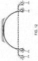
- the carcass 600 expands into the assembled belt and tread package 650 as shown in Figure 12 .
- the carcass is inflated using high volume, low pressure air.
- the pressure preferably does not exceed 280 mbar and is preferably in the range of from 210 to 280 mbar.
- the flow rate is increased from prior art process so that the system flow coefficient Cv rate is preferably about 10.
- the carcass will be stabilized in the catenary shape such that the beads are without any horizontal reaction, and the sidewall and bead are at the inflection point of direction reversal, and the carcass centerline has contacted the belt and tread package centerline.
- the hubs are then locked to the drive mechanism and slowly moved axially inward using the screw until the desired axial width of the tire is achieved and the apex is approximately at the cured ply line angle.
- the tread and shoulder area is stitched to the carcass using low stitching pressure (not shown).
- the pressure in the carcass is in the range of 350 to 800 mbar, more preferably in the range of from 500 to 700mbar.
- the stitcher cylinder pressure (not shown) is adjusted to not overly deform the carcass, using low pressure, starting at the center of the tread and stitching the tread in a circumferential manner, shifting axially outward from the center of the tire.
- the stitcher also stitches the tread shoulder interface and shoulder area.
- the completed tire is shown in Figure 13 , and the initial green tire carcass is shown in phantom.
- the tire is removed from the tire building drum completing the process.
- the green tire is then cured in a conventional mold.
- only one of the hubs has a sliding sleeve.
- one of the hubs does not move in the axial direction and has no sliding sleeve.
- the advantage of the catenary shaping process is that it does not produce any "ply pull through” into the squeegee and inner liner.
- the catenary shaping process allows the beads to move as need and the low bead locking force allow the rotation of the cable bead outer lang wire around the core wires of the cable bead.
- the plies then tacked to the outer lang wire are free to rotate along with the outer lang wires.
- Another advantage to the catenary shaping process is the tire is the carcass is shaped on a "pneumatic core" to within approximately 4 % of the final molded shape, closely approximating a tire that has been made on a core.
Landscapes
- Engineering & Computer Science (AREA)
- Mechanical Engineering (AREA)
- Manufacturing & Machinery (AREA)
- Tyre Moulding (AREA)
Abstract
Description
- The invention relates to building tires, and more particularly to a tire building drum for shaping tires and to a method of building tire.
- The manufacture of tires typically involves a tire building drum wherein, numerous tire components are applied to the drum in sequence, forming a cylindrical shaped tire carcass. The tire building drum may be a flat drum, unistage drum, a first stage drum or a high crown tire building drum. In either case, tire components are added onto the drum in succession in order to form a cylindrically shaped first stage green carcass. Next a shaping operation is performed to transform the cylindrical green carcass into a toroidally shaped green tire. Inherent stresses are often created in the green tire, particularly in the apex, bead area and sidewall due to the compression forces and compound strain applied to the carcass in order to transform the components into the desired toroidal shape. These inherent residual stresses can cause tire non-uniformity, poor handling and lower rolling resistance. Thus, an improved tire building process is thus desired that minimizes the residual tire building stresses resulting in an improved tire is desired.
- The invention relates to a tire building drum in accordance with
claim 1 or 2 and to a method in accordance with claim 8. - Dependent claims refer to preferred embodiments of the invention.
- One or more embodiments of the present invention provide a second stage tire building drum comprising a first and second hub, wherein each hub is mounted on a central shaft of the second stage tire building drum, wherein at least one of said hubs is configured for unconstrained axial movement on the central shaft, and wherein each hub has a bead receiving mechanism mounted on each hub.
- One or more embodiments of the present invention provide a second stage tire building drum comprising a first and second hub, wherein each hub is mounted on a central shaft of the second stage tire building drum, wherein at least one of said hubs is configured for unconstrained axial movement on the central shaft, wherein each hub has a bead receiving mechanism mounted on each hub, and wherein said bead receiving mechanism includes one or more bead segments. Preferably, each bead segment has a curved pocket.
- One or more embodiments of the present invention provide a second stage tire building drum comprising a first and second hub, wherein each hub is mounted on a central shaft of the second stage tire building drum, wherein at least one of said hubs is configured for unconstrained axial movement on the central shaft, wherein each hub has a bead receiving mechanism mounted on each hub, wherein the axial movement is sliding.
- One or more embodiments of the present invention provide a second stage tire building drum comprising a first and second hub, wherein each hub is mounted on a central shaft of the second stage tire building drum, wherein each hub has an inner sleeve that is mounted on the central shaft, wherein each hub has a sliding sleeve mounted on the inner sleeve and configured for unconstrained axial movement relative to the inner sleeve, and wherein each hub has a bead receiving mechanism mounted on the sliding sleeve, wherein said bead receiving mechanism includes one or more bead segments, wherein each bead segment has a curved pocket.
- One or more embodiments of the present invention provide a second stage tire building drum comprising a first and second hub, wherein each hub is mounted on a central shaft of the second stage tire building drum, wherein each hub has an inner sleeve that is mounted on the central shaft, wherein each hub has a sliding sleeve mounted on the inner sleeve and configured for unconstrained axial movement relative to the inner sleeve, and wherein each hub has a bead receiving mechanism mounted on the sliding sleeve, wherein said bead receiving mechanism includes one or more bead segments, wherein each bead segment has a curved pocket, wherein each inner sleeve is axially movable.
- One or more embodiments of the present invention provide a second stage tire building drum comprising a first and second hub, wherein each hub is mounted on a central shaft of the second stage tire building drum, wherein each hub has an inner sleeve that is mounted on the central shaft, wherein each hub has a sliding sleeve mounted on the inner sleeve and configured for unconstrained axial movement relative to the inner sleeve, and wherein each hub has a bead receiving mechanism mounted on the sliding sleeve, wherein said bead receiving mechanism includes one or more bead segments, wherein each bead segment has a curved pocket, wherein the curved pocket is concave.
- The invention provides in a first preferred aspect a second stage tire building drum comprising a first and second hub, wherein each hub is mounted on a central shaft of the second stage tire building drum; wherein each hub has an inner sleeve that is mounted on the central shaft; wherein each hub has a sliding sleeve mounted on the inner sleeve and configured for unconstrained axial sliding relative to the inner sleeve; wherein each hub has a bead receiving mechanism mounted on the sliding sleeve, wherein said bead receiving mechanism includes one or more bead segments, wherein each bead segment has a curved pocket.
- One or more embodiments of the present invention provides a second stage tire building drum comprising a first and second hub, wherein each hub is mounted on a central shaft of the second stage tire building drum, wherein each hub has an inner sleeve that is mounted on the central shaft, wherein at least one of said hubs has a sliding sleeve mounted on the inner sleeve and configured for unconstrained axial movement relative to the inner sleeve and a bead receiving mechanism mounted on the sliding sleeve, wherein the other hub has a bead receiving mechanism, and wherein said bead receiving mechanism includes one or more bead segments, wherein each bead segment has a curved pocket.
- The invention provides in a second preferred aspect a second stage tire building drum comprising: a first and second hub, wherein each hub is mounted on a central shaft of the second stage tire building drum; wherein each hub has an inner sleeve that is mounted on the central shaft; wherein at least one of said hubs has a sliding sleeve mounted on the inner sleeve and configured for unconstrained axial sliding relative to the inner sleeve and a bead receiving mechanism mounted on the sliding sleeve; wherein the other hub has a bead receiving mechanism; wherein said bead receiving mechanism includes one or more bead segments, wherein each bead segment has a curved pocket.
- One or more embodiments of the present invention provide a method of forming a tire on a tire building drum from a green tire carcass, the method comprising the steps of applying the green tire carcass onto the tire building drum by placing a first and second bead onto a first and second bead receiving member of the tire building drum, wherein no bead locking force is utilized, and inflating the carcass into engagement with a belt and tread package while at least one of the beads is free to move axially inward. Preferably, both of the beads are free to move axially inward.
- One or more embodiments of the present invention provide a method of forming a tire on a tire building drum from a green tire carcass, the method comprising the steps of applying the green tire carcass onto the tire building drum by placing a first and second bead onto a first and second bead receiving member of the tire building drum, wherein no bead locking force is utilized, and inflating the carcass into engagement with a belt and tread package while at least one of the beads is free to move axially inward, wherein at least one of the beads is slidable in the axial direction during the inflation step.
- One or more embodiments of the present invention provide a method of forming a tire on a tire building drum from a green tire carcass, the method comprising the steps of applying the green tire carcass onto the tire building drum by placing a first and second bead onto a first and second bead receiving member of the tire building drum, wherein no bead locking force is utilized, and inflating the carcass into engagement with a belt and tread package while at least one of the beads is free to move axially inward, and further including the step of radially expanding a first and second bead receiving member into engagement with a respective first and second bead at a relatively low pressure.
- One or more embodiments of the present invention provide a method of forming a tire on a tire building drum from a green tire carcass, the method comprising the steps of applying the green tire carcass onto the tire building drum by placing a first and second bead onto a first and second bead receiving member of the tire building drum, wherein no bead locking force is utilized, and inflating the carcass into engagement with a belt and tread package while at least one of the beads is free to move axially inward, wherein the carcass is inflated with a relatively high volume airflow such as with airflow having a flow coefficient Cv of 2 or more or with airflow having a flow coefficient Cv of 5 to 10.
- One or more embodiments of the present invention provide a method of forming a tire on a tire building drum from a green tire carcass, the method comprising the steps of applying the green tire carcass onto the tire building drum by placing a first and second bead onto a first and second bead receiving member of the tire building drum, wherein no bead locking force is utilized, and inflating the carcass into engagement with a belt and tread package while at least one of the beads is free to move axially inward, and wherein the carcass in inflated with a relatively high volume airflow and/or a relatively low pressure airflow.
- One or more embodiments of the present invention provide a method of forming a tire on a tire building drum comprising the steps of applying a green tire carcass onto the tire building drum by placing a first and second bead onto a first and second respective bead pocket of the tire building drum, wherein low bead locking force is utilized wherein at least one of the first and second respective bead pockets are configured for unconstrained sliding in the axial direction, and inflating the carcass into engagement with a belt and tread package while the at least one of the bead pockets is free to slide axially inward.
- The invention provides in a first preferred aspect a method of building a tire carcass on a tire building drum. The method comprises the steps of: applying the green tire carcass onto the tire building drum by placing a first and second bead onto a first and second bead receiving member of the tire building drum, wherein no bead locking force is utilized; inflating the carcass into engagement with a belt and tread package while at least one of the beads is free to move axially inward.
- The invention provides in a second preferred aspect a method of forming a tire on a tire building drum comprising the steps of: applying a green tire carcass onto the tire building drum by placing a first and second bead onto a first and second respective bead pocket of the tire building drum, wherein low bead locking force is utilized; wherein at least one of the first and second respective bead pockets are configured for unconstrained sliding in the axial direction; inflating the carcass into engagement with a belt and tread package while the at least one of the bead pockets is free to slide axially inward.
- For ease of understanding this disclosure, the following items are defined:
- "Apex" means an elastomeric filler located radially above the bead and interposed between the plies and the ply turn-up.
- "Axial" and "axially" means the lines or directions that are parallel or aligned with the longitudinal axis of rotation of the tire building drum.
- "Bead" means that part of the tire comprising an annular tensile member commonly referred to as a "bead core" wrapped by ply cords and shaped, with or without other reinforcement elements such as flippers, chippers, apexes, toe guards and chafers, to fit the design rim.
- "Belt Structure" or "Reinforcing Belts" means at least one annular layer or plies of parallel cords, woven or unwoven, underlying the tread and unanchored to the bead.
- "Carcass" means an unvulcanized laminate of tire ply material and other tire components cut to length suitable for splicing, or already spliced, into a cylindrical or toroidal shape. Additional components may be added to the carcass prior to its being vulcanized to create the molded tire.
- "Circumferential" means lines or directions extending along the perimeter of the surface of the annular tread perpendicular to the axial direction.
- "Equatorial Plane (EP)" means the plane perpendicular to the tire's axis of rotation and passing through the center of its tread.
- "Radial" and "radially" mean directions radially toward or away from the axis of rotation of the tire building drum.
- "Tread" means a rubber component which when bonded to a tire carcass includes that portion of the tire that come into contact with the road when the tire is normally inflated and under normal load.
- The invention will be described by way of example and with reference to the accompanying drawings in which:
-
Figure 1A is a front perspective view of a second stage tire building drum. -
Figure 1B is a close up perspective view of the hub of the tire building drum ofFigure 1A . -
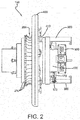
Figure 2 is a side view of a hub of the tire building drum shown inFig. 1B and positioned in an axially outward position and with the bead seal removed. -
Figure 3 is a side view of the hub offigure 2 shown in a axially inward position and with an optional pusher plate. -
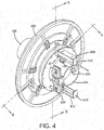
Figure 4 is a rear perspective view of the hub ofFig. 3 shown with the optional pusher plate. -
Figure 5 is a cross-sectional view of the hub ofFig. 4 in the direction 5-5. -
Figure 6A is a cross-sectional view of the hub ofFig. 4 in the direction 6-6. -
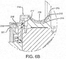
Figure 6B is a close-up view of the bead pocket seal. -
Figure 7A is a view of the hub retraction mechanism in a retracted position andFigure 7B is the hub retraction mechanism in the unretracted position. -
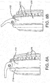
Figure 8A is a closeup view of a bead portion of a green tire carcass mounted in the bead pocket, whileFigure 8B is a close-up view of the bead of the green tire carcass. after the intended rotation of the bead area after shaping the carcass, and the bead position has moved from front of pocket to rear of pocket. -
Figure 9A is a perspective view of the hub shown with the bead lock mechanism retracted, whileFigure 9B illustrates the bead lock mechanism in the radially expanded position. -
Figure 10 is a cross-sectional view of the green tire carcass mounted in the bead pockets of the tire drum. -
Figure 11 illustrates the carcass undergoing low pressure, high volume shaping before the tread and belt package is applied. -
Figure 12 illustrates the green tire carcass inflating into the belt and tread package, with the green tire carcass shown in phantom. -
Figure 13 illustrates the tire formed by shaping and inflation, with the green tire carcass shown in phantom. - The invention provides a new and improved tire building drum and method that reduces the residual stresses in the green tire carcass, resulting in an improved tire. The process provides that the tire ply and components are shaped into a catenary structure. A catenary structure is a structure that has no tensile or compressive reactions at the base of the structure and has uniform strain along the length of the structure. In the case of a tire, the beads are the base of the structure and the length from the bead to the crown has uniform strain.
- The tire building drum and method of the present invention allows the tire to be built into a catenary shape, producing a tire that has a bead area and sidewall made with minimal strain. The tire building drum and method allows the tire to be built so that the ply cords that have the shortest cord length which are maintained in tension, and not compression. The tire building drum and method also prevents ply cord trisomy, or the unravelling of the cords due to the cords being loaded in compression and not tension.
- A first embodiment of a second stage
tire building drum 100 of the present invention is shown inFigure 1 . Thetire building drum 100 has acentral shaft 110 with a left hub 120' and aright hub 120 mounted on thecentral shaft 110. The left hub 120' is the mirror image of theright hub 120 and are otherwise mechanically identical except for the orientation. As shown inFigure 1B andFigures 2-4 , eachhub 120, 120' has aninner sleeve 130 that is secured to acentral shaft 110 of the tire building drum. Theinner sleeve 130 is connected to an internal screw (not shown) preferably withT bolts 133, so that theinner sleeve 130 may be moved in the axial direction by the internal screw. A slidingsleeve 140 is positioned over theinner sleeve 130. It is preferred that theinner sleeve 130 be bronze on steel with labyrinth grooves and glide ring seals. As shown inFigures 5-6 , each slidingsleeve 140 slides axially along theinner sleeve 130 so that thehubs 120, 120' slide axially inward towards each other or axially outward from each other. The slidingsleeve 140 may be locked into an axial position by lockingcylinders 170. The lockingcylinders 170 are mounted on theinner sleeve 130 and have a lockingmember 172 positioned for engagement with retainingbracket 300. Afirst end 305 is secured to the slidingsleeve assembly 140. A seconddistal end 310 of the retainingbracket 300 functions as an axial stop when the distal end engages the lockingmember 172, as shown infigure 3 . - Each sliding
sleeve 140 further includes abead lock mechanism 200 for receiving the bead area of the green carcass. Eachbead lock mechanism 200 further includes a plurality ofbead segments 210. Eachbead segment 210 may optionally be expanded and contracted in a radial direction bybead actuating cylinders 220. Eachbead locking mechanism 200 preferably utilizes zero or low pressure. Preferably the bead lock cylinder pressures range from zero to less than 5 bar and more preferably from zero to 2 bar. Preferably the force from the bead pockets is less than 2.07 bar over the projected area of the bead face. As distinguished from the prior art drums, exact placement of the carcass beads over the bead pockets is not required, nor is exact bead pocket location. As soon as the inflation process starts, the beads are able to pull towards the centerline of the carcass, thereby becoming centered and symmetrical to the bead pockets. As the catenary shaping of the carcass begins, the beads are freely able to move, and the carcass cord tension is very low. If the beads cannot move as in prior art drums, then the cord path is straight and horizontal, while the cord tension undesirably increases exponentially. If the bead pockets are expanded with too much force then the beads cannot move towards the inside edge of the pocket as needed and the carcass cannot become centered to the drum. Thus, the bead pocket force is preferably zero or minimal. The nonexistent or substantially reduced bead pressure is also reduced to limit bead compression and prevent cold forging of the toe guard and chafer under the bead sole. - As shown in
Figure 5 , eachbead segment 210 has a curved orconcave pocket 212 that facilitates rotation of the bead area of the tire during shaping. Eachcurved pocket 212 gently holds and supports the bead without the need of any bead lock force, although low bead lock force can be used. Thecurved pockets 212 allow the tire to rotate around the bead cable so that the tire down ply is put into tension and the apex is positioned at the cured ply line angle.Figure 8A illustrates the bead positioned in thecurved pocket 212, showing the initial bead position prior to shaping.Figure 8B illustrates the bead position in thecurved pocket 212 after shaping. Thecurved pocket 212 may be symmetrical or asymmetrical in shape. A flexibleannular seal 214 is seated over thepocket 212. As shown inFigures 6A and6B , theflexible seal 214 has afirst end 218 that is secured to the housing of the bead pocket. Theseal 214 has overlappingportions foot 217 that is received within a groove of the housing. The seal has acurved portion 216 that is seated in thepocket 212. The seal terminates in afree end 215. The free end is not secured, and floats, resulting in good sealing with no large forces required by the bead lock cylinder to open the bead pockets and overcome the seal restrictive forces. -
Figure 9A illustrates the bead segments in the retracted position, whileFigure 9B illustrates the bead segments in their radially expanded position. -
Figures 1-6 illustrate that thehubs 120 may further include anoptional shaping plate 400. Theoptional shaping plate 400 is received insupport brackets 410, as shown inFig 2 . Theoptional shaping plate 400 may assist the shaping process by engaging the mid sidewall of the tire during the shaping process. The air pressure in the cylinder mover for shapingplate 400 can be variably controlled. -
Figures 7A illustrates aretraction mechanism 500 that is useful to reposition the sliding sleeve in the desired axial location. Theretraction mechanism 500 includes a chain attached to the sliding sleeve to slide the sleeve into the home or start position. Theretraction mechanism 500 is mounted on thestationary sleeve housing 130. - The first step of the catenary method of building tires begins with the tire building drum located in the start position as shown in
Figure 1 . The slidingsleeve 140 is locked to the innerstationary sleeve 130. A cylindrically shapedgreen tire carcass 610 is mounted on thebead mechanisms 200 on eachhub 120, so that arespective bead area 600 is received in thebead pocket 210 of a respective hub, as shown inFigure 9 andFig 10 . - The
bead locking mechanisms 200 may optionally be radially expanded to exert a low-pressure force on the beads. As distinguished from the prior art drums, exact placement of the carcass beads over the bead pockets is not required, nor is exact bead pocket location. As soon as the inflation process starts, the beads are able to pull towards the centerline of the carcass, thereby becoming centered and symmetrical to the bead pockets. As the catenary shaping of the carcass begins, the beads are freely able to move, and the carcass cord tension is very low. If the beads cannot move as in prior art drums, then the cord path is straight and horizontal, while the cord tension undesirably increases exponentially. If the bead pockets are expanded with too much force then the beads cannot move towards the inside edge of the pocket as needed and the carcass cannot become centered to the drum. Thus, the bead pocket force is preferably zero or minimal. - After the green tire carcass is loaded, the next step is to shape the green carcass using the catenary shaping process of the invention. As the tire drum rotates, the
green carcass 610 is slowly inflated using low pressure, high volume shaping air. The lockingmember 172 is unlocked from the retainingmember 300, allowing the slidingsleeve 140 to freely slide axially inward towards the adjacent hub. During inflation, the carcass cord tension is maintained at a low tension due to the evolvement of the catenary shape and the free sliding movement of the beads mounted on the sliding sleeves, which are each free to move in the axial direction. The shaping air pressure is very low at the level needed to gently strain and overcome the carcass composite stiffness. The carcass is self-shaping itself to the balanced catenary shape. Thus, each sliding sleeve is free to move in the axial direction towards the other sliding sleeve so that the tire is shaped by the tension of the ply cords as shown inFigure 10 . Typically, each sliding sleeve may axially slide in the range of 152.4 mm to 254 mm. The shape of the bead pocket segments allow the tire bead area to rotate during shaping without the need for high bead clamping forces. The bead lock forces can be zero or be minimal. - The assembled belt and
tread package 650 is positioned over the inflatingcarcass 600 as shown inFig. 11 . Thecarcass 600 expands into the assembled belt andtread package 650 as shown inFigure 12 . The carcass is inflated using high volume, low pressure air. The pressure preferably does not exceed 280 mbar and is preferably in the range of from 210 to 280 mbar. The flow rate is increased from prior art process so that the system flow coefficient Cv rate is preferably about 10. After the tire is approximately 80% of the desired shape, the carcass will be stabilized in the catenary shape such that the beads are without any horizontal reaction, and the sidewall and bead are at the inflection point of direction reversal, and the carcass centerline has contacted the belt and tread package centerline. One the carcass has been stabilized in the catenary shape, then the hubs are then locked to the drive mechanism and slowly moved axially inward using the screw until the desired axial width of the tire is achieved and the apex is approximately at the cured ply line angle. Next, the tread and shoulder area is stitched to the carcass using low stitching pressure (not shown). The pressure in the carcass is in the range of 350 to 800 mbar, more preferably in the range of from 500 to 700mbar. The stitcher cylinder pressure (not shown) is adjusted to not overly deform the carcass, using low pressure, starting at the center of the tread and stitching the tread in a circumferential manner, shifting axially outward from the center of the tire. The stitcher also stitches the tread shoulder interface and shoulder area. The completed tire is shown inFigure 13 , and the initial green tire carcass is shown in phantom. - Then the tire is removed from the tire building drum completing the process. The green tire is then cured in a conventional mold.
- In an alternate embodiment of the invention, only one of the hubs has a sliding sleeve.
- In an alternate embodiment of the invention, one of the hubs does not move in the axial direction and has no sliding sleeve.
- The advantage of the catenary shaping process is that it does not produce any "ply pull through" into the squeegee and inner liner. The catenary shaping process allows the beads to move as need and the low bead locking force allow the rotation of the cable bead outer lang wire around the core wires of the cable bead. The plies then tacked to the outer lang wire are free to rotate along with the outer lang wires. There is no elastic energy in the outer lang wire when the wire is rotated so the ending rotational angle of the bead carcass elements is saved. Another advantage to the catenary shaping process is the tire is the carcass is shaped on a "pneumatic core" to within approximately 4 % of the final molded shape, closely approximating a tire that has been made on a core.
Claims (15)
- A second stage tire building drum, the drum (100) comprising:a first and second hub (120, 120'), wherein each hub is mounted on a central shaft (110) of the second stage tire building drum (100);wherein at least one of said hubs (120, 120') is configured for unconstrained axial movement on the central shaft (110); andwherein each hub (120, 120') has a bead receiving mechanism mounted on each hub.
- A second stage tire building drum comprising a first and second hub (120, 120'), wherein each hub is mounted on a central shaft (110) of the second stage tire building drum (100) and each hub has an inner sleeve (130) that is mounted on the central shaft; wherein(i) each hub (120, 120') has a sliding sleeve (140) mounted on the inner sleeve (130) and configured for unconstrained axial movement relative to the inner sleeve, and each hub (120, 120') has a bead receiving mechanism mounted on the sliding sleeve (140), or(ii) at least one of said hubs (120, 120') has a sliding sleeve (140) mounted on the inner sleeve (130) and configured for unconstrained axial movement relative to the inner sleeve and a bead receiving mechanism mounted on the sliding sleeve (140), and the other hub has a bead receiving mechanism;and wherein at least one or all of the bead receiving mechanisms includes one or more bead segments (210), each bead segment having a curved pocket (212).
- The second stage tire building drum of claim 1 wherein said bead receiving mechanism includes one or more bead segments (210).
- The second stage tire building drum of claim 2 wherein each bead segment (210) has a curved pocket (212).
- The second stage tire building drum of claim 1, 3 or 4 wherein the axial movement is sliding.
- The second stage tire building drum of claim 2 wherein each inner sleeve (130) is axially movable.
- The second stage tire building drum of at least one of the previous claims wherein the curved pocket (212) is concave.
- A method of forming a tire on a tire building drum (100) from a green tire carcass (600), the method comprising the steps of:(i) applying a green tire carcass (600) onto the tire building drum (100) by placing a first and second bead onto a first and second respective bead receiving member of the tire building drum, wherein no bead locking force is utilized; or(ii) applying a green tire carcass (600) onto the tire building drum (100) by placing a first and second bead onto a first and second respective bead pocket (212) of the tire building drum (100), wherein preferably a relatively low bead locking force is utilized and wherein at least one of the first and second respective bead pockets (212) are configured for unconstrained sliding in the axial direction;and inflating the carcass (600) into engagement with a belt and tread package (650) while at least one of the beads is free to move axially inward.
- The method of claim 8 wherein both of the beads are free to move axially inward.
- The method of claim 8 or 9 wherein at least one of the beads is slidable in the axial direction during the inflation step.
- The method of at least one of the claims 8 to 10 further including the step of radially expanding a first and second bead receiving member into engagement with a respective first and second bead at a relatively low pressure.
- The method of claim 8 wherein the carcass is inflated with airflow having a flow coefficient Cv of 2 or more or in a range of from 5 to 10.
- The method of claim 8 or 12 wherein the carcass in inflated with a relatively high volume airflow.
- The method of claim 8, 12 or 13 wherein the carcass in inflated with low pressure airflow, preferably a with pressure of not more than 280 mbar or in a range of from 210 to 280 mbar.
- The method of at least one of the previous claims 8 to 14 wherein the relatively low bead locking force is a force corresponding to a pressure of less than 5 bar, preferably less than 2.07 bar or from 0 bar to 2 bar, over the projected area of the bead face.
Applications Claiming Priority (2)
| Application Number | Priority Date | Filing Date | Title |
|---|---|---|---|
| US15/693,776 US20190070812A1 (en) | 2017-09-01 | 2017-09-01 | Method of building a tire |
| US15/693,773 US20190070811A1 (en) | 2017-09-01 | 2017-09-01 | Tire building drum |
Publications (2)
| Publication Number | Publication Date |
|---|---|
| EP3450153A1 true EP3450153A1 (en) | 2019-03-06 |
| EP3450153B1 EP3450153B1 (en) | 2020-07-29 |
Family
ID=63452445
Family Applications (1)
| Application Number | Title | Priority Date | Filing Date |
|---|---|---|---|
| EP18191823.6A Active EP3450153B1 (en) | 2017-09-01 | 2018-08-30 | Tire building drum and method of building a tire |
Country Status (1)
| Country | Link |
|---|---|
| EP (1) | EP3450153B1 (en) |
Citations (3)
| Publication number | Priority date | Publication date | Assignee | Title |
|---|---|---|---|---|
| US20150059984A1 (en) * | 2013-08-29 | 2015-03-05 | The Goodyear Tire & Rubber Company | Tire building drum |
| US20150114571A1 (en) * | 2013-10-29 | 2015-04-30 | The Goodyear Tire & Rubber Company | Uni-stage tire building drum |
| US20160176138A1 (en) * | 2014-12-23 | 2016-06-23 | The Goodyear Tire & Rubber Company | Sleeveless tire building drum |
-
2018
- 2018-08-30 EP EP18191823.6A patent/EP3450153B1/en active Active
Patent Citations (3)
| Publication number | Priority date | Publication date | Assignee | Title |
|---|---|---|---|---|
| US20150059984A1 (en) * | 2013-08-29 | 2015-03-05 | The Goodyear Tire & Rubber Company | Tire building drum |
| US20150114571A1 (en) * | 2013-10-29 | 2015-04-30 | The Goodyear Tire & Rubber Company | Uni-stage tire building drum |
| US20160176138A1 (en) * | 2014-12-23 | 2016-06-23 | The Goodyear Tire & Rubber Company | Sleeveless tire building drum |
Also Published As
| Publication number | Publication date |
|---|---|
| EP3450153B1 (en) | 2020-07-29 |
Similar Documents
| Publication | Publication Date | Title |
|---|---|---|
| US7288160B2 (en) | Method of making a tire using a high crown uni-stage tire building drum | |
| JP4943702B2 (en) | High crown single stage tire building drum | |
| US10259181B2 (en) | Sleeveless tire building drum | |
| EP1504883B1 (en) | High crown first stage tire building drum | |
| US20160176138A1 (en) | Sleeveless tire building drum | |
| US20150114571A1 (en) | Uni-stage tire building drum | |
| CN104416935B (en) | tire building drum | |
| US20140048213A1 (en) | Sleeveless tire building drum with interchangeable width elements | |
| EP3450151B1 (en) | Method of making a tire | |
| US20190070814A1 (en) | Method of building tires | |
| US6630045B1 (en) | Combined bead loading and apex application system | |
| CN109421298B (en) | Methods of building tires | |
| CN109421302B (en) | Method of building a tyre | |
| EP3450153B1 (en) | Tire building drum and method of building a tire | |
| EP3450152B1 (en) | Method of making a tire and tire building drum | |
| US20190070813A1 (en) | Tire building drum | |
| EP1165306B1 (en) | Combined bead loading and apex application system | |
| EP3450154B1 (en) | Tire building drum and method of building a tire | |
| CN113002035B (en) | Tire building drum and method of building a tire | |
| CN1668453A (en) | Method and apparatus for manufacturing tyre | |
| KR20050083818A (en) | Method and apparatus for manufacturing a pneumatic tyre for vehicle wheels |
Legal Events
| Date | Code | Title | Description |
|---|---|---|---|
| PUAI | Public reference made under article 153(3) epc to a published international application that has entered the european phase |
Free format text: ORIGINAL CODE: 0009012 |
|
| STAA | Information on the status of an ep patent application or granted ep patent |
Free format text: STATUS: THE APPLICATION HAS BEEN PUBLISHED |
|
| AK | Designated contracting states |
Kind code of ref document: A1 Designated state(s): AL AT BE BG CH CY CZ DE DK EE ES FI FR GB GR HR HU IE IS IT LI LT LU LV MC MK MT NL NO PL PT RO RS SE SI SK SM TR |
|
| AX | Request for extension of the european patent |
Extension state: BA ME |
|
| RIN1 | Information on inventor provided before grant (corrected) |
Inventor name: STOILA, GEORGE MICHAEL Inventor name: HOGAN, MICHAEL JAMES Inventor name: MORALES, PABLO RAFAEL Inventor name: KMIECIK, FRANK ANTHONY Inventor name: MONTGOMERY, MARK JOHN Inventor name: VARGO, RICHARD DAVID Inventor name: YAO, MINWU Inventor name: ANDERSON, JOHN EDWARD Inventor name: JOHNSON, KRISTIAN DANIEL Inventor name: ONDO, ANDREW ROBERT |
|
| STAA | Information on the status of an ep patent application or granted ep patent |
Free format text: STATUS: REQUEST FOR EXAMINATION WAS MADE |
|
| 17P | Request for examination filed |
Effective date: 20190906 |
|
| RBV | Designated contracting states (corrected) |
Designated state(s): AL AT BE BG CH CY CZ DE DK EE ES FI FR GB GR HR HU IE IS IT LI LT LU LV MC MK MT NL NO PL PT RO RS SE SI SK SM TR |
|
| GRAP | Despatch of communication of intention to grant a patent |
Free format text: ORIGINAL CODE: EPIDOSNIGR1 |
|
| STAA | Information on the status of an ep patent application or granted ep patent |
Free format text: STATUS: GRANT OF PATENT IS INTENDED |
|
| RIC1 | Information provided on ipc code assigned before grant |
Ipc: B29D 30/32 20060101ALI20200124BHEP Ipc: B29D 30/24 20060101AFI20200124BHEP |
|
| INTG | Intention to grant announced |
Effective date: 20200213 |
|
| GRAS | Grant fee paid |
Free format text: ORIGINAL CODE: EPIDOSNIGR3 |
|
| GRAA | (expected) grant |
Free format text: ORIGINAL CODE: 0009210 |
|
| STAA | Information on the status of an ep patent application or granted ep patent |
Free format text: STATUS: THE PATENT HAS BEEN GRANTED |
|
| AK | Designated contracting states |
Kind code of ref document: B1 Designated state(s): AL AT BE BG CH CY CZ DE DK EE ES FI FR GB GR HR HU IE IS IT LI LT LU LV MC MK MT NL NO PL PT RO RS SE SI SK SM TR |
|
| REG | Reference to a national code |
Ref country code: CH Ref legal event code: EP |
|
| REG | Reference to a national code |
Ref country code: AT Ref legal event code: REF Ref document number: 1295309 Country of ref document: AT Kind code of ref document: T Effective date: 20200815 |
|
| REG | Reference to a national code |
Ref country code: IE Ref legal event code: FG4D |
|
| REG | Reference to a national code |
Ref country code: DE Ref legal event code: R096 Ref document number: 602018006405 Country of ref document: DE |
|
| REG | Reference to a national code |
Ref country code: NL Ref legal event code: FP |
|
| REG | Reference to a national code |
Ref country code: LT Ref legal event code: MG4D |
|
| REG | Reference to a national code |
Ref country code: AT Ref legal event code: MK05 Ref document number: 1295309 Country of ref document: AT Kind code of ref document: T Effective date: 20200729 |
|
| PG25 | Lapsed in a contracting state [announced via postgrant information from national office to epo] |
Ref country code: PT Free format text: LAPSE BECAUSE OF FAILURE TO SUBMIT A TRANSLATION OF THE DESCRIPTION OR TO PAY THE FEE WITHIN THE PRESCRIBED TIME-LIMIT Effective date: 20201130 Ref country code: SE Free format text: LAPSE BECAUSE OF FAILURE TO SUBMIT A TRANSLATION OF THE DESCRIPTION OR TO PAY THE FEE WITHIN THE PRESCRIBED TIME-LIMIT Effective date: 20200729 Ref country code: HR Free format text: LAPSE BECAUSE OF FAILURE TO SUBMIT A TRANSLATION OF THE DESCRIPTION OR TO PAY THE FEE WITHIN THE PRESCRIBED TIME-LIMIT Effective date: 20200729 Ref country code: LT Free format text: LAPSE BECAUSE OF FAILURE TO SUBMIT A TRANSLATION OF THE DESCRIPTION OR TO PAY THE FEE WITHIN THE PRESCRIBED TIME-LIMIT Effective date: 20200729 Ref country code: FI Free format text: LAPSE BECAUSE OF FAILURE TO SUBMIT A TRANSLATION OF THE DESCRIPTION OR TO PAY THE FEE WITHIN THE PRESCRIBED TIME-LIMIT Effective date: 20200729 Ref country code: GR Free format text: LAPSE BECAUSE OF FAILURE TO SUBMIT A TRANSLATION OF THE DESCRIPTION OR TO PAY THE FEE WITHIN THE PRESCRIBED TIME-LIMIT Effective date: 20201030 Ref country code: BG Free format text: LAPSE BECAUSE OF FAILURE TO SUBMIT A TRANSLATION OF THE DESCRIPTION OR TO PAY THE FEE WITHIN THE PRESCRIBED TIME-LIMIT Effective date: 20201029 Ref country code: AT Free format text: LAPSE BECAUSE OF FAILURE TO SUBMIT A TRANSLATION OF THE DESCRIPTION OR TO PAY THE FEE WITHIN THE PRESCRIBED TIME-LIMIT Effective date: 20200729 Ref country code: NO Free format text: LAPSE BECAUSE OF FAILURE TO SUBMIT A TRANSLATION OF THE DESCRIPTION OR TO PAY THE FEE WITHIN THE PRESCRIBED TIME-LIMIT Effective date: 20201029 Ref country code: ES Free format text: LAPSE BECAUSE OF FAILURE TO SUBMIT A TRANSLATION OF THE DESCRIPTION OR TO PAY THE FEE WITHIN THE PRESCRIBED TIME-LIMIT Effective date: 20200729 |
|
| PG25 | Lapsed in a contracting state [announced via postgrant information from national office to epo] |
Ref country code: IS Free format text: LAPSE BECAUSE OF FAILURE TO SUBMIT A TRANSLATION OF THE DESCRIPTION OR TO PAY THE FEE WITHIN THE PRESCRIBED TIME-LIMIT Effective date: 20201129 Ref country code: PL Free format text: LAPSE BECAUSE OF FAILURE TO SUBMIT A TRANSLATION OF THE DESCRIPTION OR TO PAY THE FEE WITHIN THE PRESCRIBED TIME-LIMIT Effective date: 20200729 Ref country code: RS Free format text: LAPSE BECAUSE OF FAILURE TO SUBMIT A TRANSLATION OF THE DESCRIPTION OR TO PAY THE FEE WITHIN THE PRESCRIBED TIME-LIMIT Effective date: 20200729 Ref country code: LV Free format text: LAPSE BECAUSE OF FAILURE TO SUBMIT A TRANSLATION OF THE DESCRIPTION OR TO PAY THE FEE WITHIN THE PRESCRIBED TIME-LIMIT Effective date: 20200729 |
|
| PG25 | Lapsed in a contracting state [announced via postgrant information from national office to epo] |
Ref country code: EE Free format text: LAPSE BECAUSE OF FAILURE TO SUBMIT A TRANSLATION OF THE DESCRIPTION OR TO PAY THE FEE WITHIN THE PRESCRIBED TIME-LIMIT Effective date: 20200729 Ref country code: DK Free format text: LAPSE BECAUSE OF FAILURE TO SUBMIT A TRANSLATION OF THE DESCRIPTION OR TO PAY THE FEE WITHIN THE PRESCRIBED TIME-LIMIT Effective date: 20200729 Ref country code: CZ Free format text: LAPSE BECAUSE OF FAILURE TO SUBMIT A TRANSLATION OF THE DESCRIPTION OR TO PAY THE FEE WITHIN THE PRESCRIBED TIME-LIMIT Effective date: 20200729 Ref country code: RO Free format text: LAPSE BECAUSE OF FAILURE TO SUBMIT A TRANSLATION OF THE DESCRIPTION OR TO PAY THE FEE WITHIN THE PRESCRIBED TIME-LIMIT Effective date: 20200729 Ref country code: SM Free format text: LAPSE BECAUSE OF FAILURE TO SUBMIT A TRANSLATION OF THE DESCRIPTION OR TO PAY THE FEE WITHIN THE PRESCRIBED TIME-LIMIT Effective date: 20200729 Ref country code: LU Free format text: LAPSE BECAUSE OF NON-PAYMENT OF DUE FEES Effective date: 20200830 |
|
| REG | Reference to a national code |
Ref country code: DE Ref legal event code: R097 Ref document number: 602018006405 Country of ref document: DE |
|
| REG | Reference to a national code |
Ref country code: BE Ref legal event code: MM Effective date: 20200831 |
|
| PG25 | Lapsed in a contracting state [announced via postgrant information from national office to epo] |
Ref country code: AL Free format text: LAPSE BECAUSE OF FAILURE TO SUBMIT A TRANSLATION OF THE DESCRIPTION OR TO PAY THE FEE WITHIN THE PRESCRIBED TIME-LIMIT Effective date: 20200729 |
|
| PLBE | No opposition filed within time limit |
Free format text: ORIGINAL CODE: 0009261 |
|
| STAA | Information on the status of an ep patent application or granted ep patent |
Free format text: STATUS: NO OPPOSITION FILED WITHIN TIME LIMIT |
|
| PG25 | Lapsed in a contracting state [announced via postgrant information from national office to epo] |
Ref country code: SK Free format text: LAPSE BECAUSE OF FAILURE TO SUBMIT A TRANSLATION OF THE DESCRIPTION OR TO PAY THE FEE WITHIN THE PRESCRIBED TIME-LIMIT Effective date: 20200729 |
|
| 26N | No opposition filed |
Effective date: 20210430 |
|
| PG25 | Lapsed in a contracting state [announced via postgrant information from national office to epo] |
Ref country code: BE Free format text: LAPSE BECAUSE OF NON-PAYMENT OF DUE FEES Effective date: 20200831 Ref country code: SI Free format text: LAPSE BECAUSE OF FAILURE TO SUBMIT A TRANSLATION OF THE DESCRIPTION OR TO PAY THE FEE WITHIN THE PRESCRIBED TIME-LIMIT Effective date: 20200729 Ref country code: IE Free format text: LAPSE BECAUSE OF NON-PAYMENT OF DUE FEES Effective date: 20200830 |
|
| REG | Reference to a national code |
Ref country code: CH Ref legal event code: PL |
|
| PG25 | Lapsed in a contracting state [announced via postgrant information from national office to epo] |
Ref country code: LI Free format text: LAPSE BECAUSE OF NON-PAYMENT OF DUE FEES Effective date: 20210831 Ref country code: CH Free format text: LAPSE BECAUSE OF NON-PAYMENT OF DUE FEES Effective date: 20210831 |
|
| PG25 | Lapsed in a contracting state [announced via postgrant information from national office to epo] |
Ref country code: TR Free format text: LAPSE BECAUSE OF FAILURE TO SUBMIT A TRANSLATION OF THE DESCRIPTION OR TO PAY THE FEE WITHIN THE PRESCRIBED TIME-LIMIT Effective date: 20200729 Ref country code: MT Free format text: LAPSE BECAUSE OF FAILURE TO SUBMIT A TRANSLATION OF THE DESCRIPTION OR TO PAY THE FEE WITHIN THE PRESCRIBED TIME-LIMIT Effective date: 20200729 Ref country code: CY Free format text: LAPSE BECAUSE OF FAILURE TO SUBMIT A TRANSLATION OF THE DESCRIPTION OR TO PAY THE FEE WITHIN THE PRESCRIBED TIME-LIMIT Effective date: 20200729 |
|
| PG25 | Lapsed in a contracting state [announced via postgrant information from national office to epo] |
Ref country code: MK Free format text: LAPSE BECAUSE OF FAILURE TO SUBMIT A TRANSLATION OF THE DESCRIPTION OR TO PAY THE FEE WITHIN THE PRESCRIBED TIME-LIMIT Effective date: 20200729 Ref country code: MC Free format text: LAPSE BECAUSE OF FAILURE TO SUBMIT A TRANSLATION OF THE DESCRIPTION OR TO PAY THE FEE WITHIN THE PRESCRIBED TIME-LIMIT Effective date: 20200729 |
|
| PGFP | Annual fee paid to national office [announced via postgrant information from national office to epo] |
Ref country code: NL Payment date: 20220715 Year of fee payment: 5 |
|
| PGFP | Annual fee paid to national office [announced via postgrant information from national office to epo] |
Ref country code: IT Payment date: 20220712 Year of fee payment: 5 Ref country code: DE Payment date: 20220608 Year of fee payment: 5 |
|
| PGFP | Annual fee paid to national office [announced via postgrant information from national office to epo] |
Ref country code: FR Payment date: 20220709 Year of fee payment: 5 |
|
| GBPC | Gb: european patent ceased through non-payment of renewal fee |
Effective date: 20220830 |
|
| PG25 | Lapsed in a contracting state [announced via postgrant information from national office to epo] |
Ref country code: GB Free format text: LAPSE BECAUSE OF NON-PAYMENT OF DUE FEES Effective date: 20220830 |
|
| REG | Reference to a national code |
Ref country code: DE Ref legal event code: R119 Ref document number: 602018006405 Country of ref document: DE |
|
| REG | Reference to a national code |
Ref country code: NL Ref legal event code: MM Effective date: 20230901 |
|
| PG25 | Lapsed in a contracting state [announced via postgrant information from national office to epo] |
Ref country code: NL Free format text: LAPSE BECAUSE OF NON-PAYMENT OF DUE FEES Effective date: 20230901 |
|
| PG25 | Lapsed in a contracting state [announced via postgrant information from national office to epo] |
Ref country code: NL Free format text: LAPSE BECAUSE OF NON-PAYMENT OF DUE FEES Effective date: 20230901 |
|
| PG25 | Lapsed in a contracting state [announced via postgrant information from national office to epo] |
Ref country code: IT Free format text: LAPSE BECAUSE OF NON-PAYMENT OF DUE FEES Effective date: 20230830 Ref country code: FR Free format text: LAPSE BECAUSE OF NON-PAYMENT OF DUE FEES Effective date: 20230831 Ref country code: DE Free format text: LAPSE BECAUSE OF NON-PAYMENT OF DUE FEES Effective date: 20240301 |