EP3450065A1 - Cutting insert - Google Patents
Cutting insert Download PDFInfo
- Publication number
- EP3450065A1 EP3450065A1 EP17789095.1A EP17789095A EP3450065A1 EP 3450065 A1 EP3450065 A1 EP 3450065A1 EP 17789095 A EP17789095 A EP 17789095A EP 3450065 A1 EP3450065 A1 EP 3450065A1
- Authority
- EP
- European Patent Office
- Prior art keywords
- pair
- cutting
- lateral
- chip
- cutting insert
- Prior art date
- Legal status (The legal status is an assumption and is not a legal conclusion. Google has not performed a legal analysis and makes no representation as to the accuracy of the status listed.)
- Pending
Links
Images




Classifications
-
- B—PERFORMING OPERATIONS; TRANSPORTING
- B23—MACHINE TOOLS; METAL-WORKING NOT OTHERWISE PROVIDED FOR
- B23B—TURNING; BORING
- B23B27/00—Tools for turning or boring machines; Tools of a similar kind in general; Accessories therefor
- B23B27/04—Cutting-off tools
- B23B27/045—Cutting-off tools with chip-breaking arrangements
-
- B—PERFORMING OPERATIONS; TRANSPORTING
- B23—MACHINE TOOLS; METAL-WORKING NOT OTHERWISE PROVIDED FOR
- B23B—TURNING; BORING
- B23B27/00—Tools for turning or boring machines; Tools of a similar kind in general; Accessories therefor
- B23B27/14—Cutting tools of which the bits or tips or cutting inserts are of special material
- B23B27/18—Cutting tools of which the bits or tips or cutting inserts are of special material with cutting bits or tips or cutting inserts rigidly mounted, e.g. by brazing
- B23B27/20—Cutting tools of which the bits or tips or cutting inserts are of special material with cutting bits or tips or cutting inserts rigidly mounted, e.g. by brazing with diamond bits or cutting inserts
-
- B—PERFORMING OPERATIONS; TRANSPORTING
- B23—MACHINE TOOLS; METAL-WORKING NOT OTHERWISE PROVIDED FOR
- B23B—TURNING; BORING
- B23B27/00—Tools for turning or boring machines; Tools of a similar kind in general; Accessories therefor
- B23B27/04—Cutting-off tools
-
- B—PERFORMING OPERATIONS; TRANSPORTING
- B23—MACHINE TOOLS; METAL-WORKING NOT OTHERWISE PROVIDED FOR
- B23B—TURNING; BORING
- B23B27/00—Tools for turning or boring machines; Tools of a similar kind in general; Accessories therefor
- B23B27/06—Profile cutting tools, i.e. forming-tools
- B23B27/065—Thread-turning tools
-
- B—PERFORMING OPERATIONS; TRANSPORTING
- B23—MACHINE TOOLS; METAL-WORKING NOT OTHERWISE PROVIDED FOR
- B23B—TURNING; BORING
- B23B27/00—Tools for turning or boring machines; Tools of a similar kind in general; Accessories therefor
- B23B27/14—Cutting tools of which the bits or tips or cutting inserts are of special material
-
- B—PERFORMING OPERATIONS; TRANSPORTING
- B23—MACHINE TOOLS; METAL-WORKING NOT OTHERWISE PROVIDED FOR
- B23B—TURNING; BORING
- B23B27/00—Tools for turning or boring machines; Tools of a similar kind in general; Accessories therefor
- B23B27/14—Cutting tools of which the bits or tips or cutting inserts are of special material
- B23B27/148—Composition of the cutting inserts
-
- B—PERFORMING OPERATIONS; TRANSPORTING
- B23—MACHINE TOOLS; METAL-WORKING NOT OTHERWISE PROVIDED FOR
- B23B—TURNING; BORING
- B23B27/00—Tools for turning or boring machines; Tools of a similar kind in general; Accessories therefor
- B23B27/22—Cutting tools with chip-breaking equipment
-
- B—PERFORMING OPERATIONS; TRANSPORTING
- B23—MACHINE TOOLS; METAL-WORKING NOT OTHERWISE PROVIDED FOR
- B23B—TURNING; BORING
- B23B2200/00—Details of cutting inserts
- B23B2200/04—Overall shape
- B23B2200/0423—Irregular
-
- B—PERFORMING OPERATIONS; TRANSPORTING
- B23—MACHINE TOOLS; METAL-WORKING NOT OTHERWISE PROVIDED FOR
- B23B—TURNING; BORING
- B23B2200/00—Details of cutting inserts
- B23B2200/08—Rake or top surfaces
- B23B2200/081—Rake or top surfaces with projections
-
- B—PERFORMING OPERATIONS; TRANSPORTING
- B23—MACHINE TOOLS; METAL-WORKING NOT OTHERWISE PROVIDED FOR
- B23B—TURNING; BORING
- B23B2200/00—Details of cutting inserts
- B23B2200/08—Rake or top surfaces
- B23B2200/086—Rake or top surfaces with one or more grooves
-
- B—PERFORMING OPERATIONS; TRANSPORTING
- B23—MACHINE TOOLS; METAL-WORKING NOT OTHERWISE PROVIDED FOR
- B23B—TURNING; BORING
- B23B2200/00—Details of cutting inserts
- B23B2200/08—Rake or top surfaces
- B23B2200/086—Rake or top surfaces with one or more grooves
- B23B2200/087—Rake or top surfaces with one or more grooves for chip breaking
-
- B—PERFORMING OPERATIONS; TRANSPORTING
- B23—MACHINE TOOLS; METAL-WORKING NOT OTHERWISE PROVIDED FOR
- B23B—TURNING; BORING
- B23B2200/00—Details of cutting inserts
- B23B2200/32—Chip breaking or chip evacuation
- B23B2200/321—Chip breaking or chip evacuation by chip breaking projections
-
- B—PERFORMING OPERATIONS; TRANSPORTING
- B23—MACHINE TOOLS; METAL-WORKING NOT OTHERWISE PROVIDED FOR
- B23B—TURNING; BORING
- B23B2200/00—Details of cutting inserts
- B23B2200/32—Chip breaking or chip evacuation
- B23B2200/323—Chip breaking or chip evacuation by chip breaking depressions
-
- B—PERFORMING OPERATIONS; TRANSPORTING
- B23—MACHINE TOOLS; METAL-WORKING NOT OTHERWISE PROVIDED FOR
- B23B—TURNING; BORING
- B23B2226/00—Materials of tools or workpieces not comprising a metal
- B23B2226/31—Diamond
-
- B—PERFORMING OPERATIONS; TRANSPORTING
- B23—MACHINE TOOLS; METAL-WORKING NOT OTHERWISE PROVIDED FOR
- B23B—TURNING; BORING
- B23B2226/00—Materials of tools or workpieces not comprising a metal
- B23B2226/31—Diamond
- B23B2226/315—Diamond polycrystalline [PCD]
Definitions
- the present invention relates to cutting inserts.
- the present application claims the priority benefit of Japanese Patent Application No. 2016-089268 filed on April 27, 2016 , the contents of which are incorporated herein by reference in its entirety.
- Japanese Patent Laying-Open No. 2008-272923 discloses a cutting insert that grooves, for example, a workpiece such as steel.
- the material for an edge portion of the cutting insert is cemented carbide.
- cemented carbide easily welds the workpiece to a blade tip. This leads to a shorter lifetime of the cutting insert, so that the workpiece cannot have good surface quality.
- Japanese Patent Laying-Open No. 7-314204 discloses a cutting insert, where the material for an edge portion is a diamond sintered compact and the material for a substrate holding the edge portion is cemented carbide. Changing the material for the edge portion from cemented carbide to diamond sintered compact can significantly reduce welding of a workpiece to the edge portion.
- diamond is difficult to process because it is a material with very high hardness which easily chips.
- the cutting insert thus has a breaker wall provided in the substrate, not in the edge portion.
- a cutting insert includes a body and an edge portion provided on the body.
- the edge portion includes an upper surface, a side surface, and a land surface.
- the side surface has a front side surface and a pair of lateral side surfaces adjacent to the front side surface. An intersection between the land surface and the front side surface form a front cutting edge. An intersection between the land surface and each of the pair of lateral side surfaces forms a corresponding one of a pair of lateral cutting edges.
- the edge portion contains 80 vol% or more of diamond.
- a chip breaker recess is provided between the upper surface and the land surface. Surfaces forming the chip breaker recess include a rake face continuous with the land surface and a breaker wall surface continuous with the upper surface.
- the upper surface has a front edge portion opposite to the front cutting edge from the chip breaker recess. The pair of protruding portions are provided to extend from the front edge portion toward the front cutting edge.
- the material for the breaker wall of the cutting insert described in Japanese Patent Laying-Open No. 07-314204 is cemented carbide.
- a workpiece such as aluminum alloy
- the direction in which a chip flows can be controlled, but the chip cannot be divided due to high toughness of the material. If the chip is not divided, the workpiece substantially cannot be processed because the elongated chip is twisted around the workpiece.
- the cutting insert has a breaker wall provided only at the location remote from the blade tip in the grooving direction and has no breaker wall provided at a location in the cross-feed direction. In cross-feeding with the cutting insert, accordingly, a chip cannot be divided because the chip cannot be controlled.
- An object of an aspect of the present invention is to provide a cutting tool capable of dividing a chip in both of grooving and cross-feeding.
- a cutting tool capable of dividing a chip in both of grooving and cross-feeding can be provided.
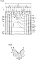
- cutting insert 30 mainly includes a body 1 and an edge portion 2.
- Edge portion 2 is provided on body 1.
- Edge portion 2 is provided, for example, on a surface of a projecting portion of body 1.
- Body 1 has, for example, a fastening hole 20.
- the material for body 1 is, for example, cemented carbide or steel.
- edge portion 2 includes an upper surface 4, a side surface 32, and a land surface 9.
- Side surface 32 mainly has a front side surface 5 and a pair of lateral side surfaces 6 adjacent to front side surface 5.
- Edge portion 2 contains 80 vol% or more of diamond.
- Edge portion 2 is formed of, for example, a diamond sintered compact. Diamond may be polycrystalline diamond or single crystal diamond. Edge portion 2 preferably contains 90 vol% or more, more preferably, 95 vol% or more of diamond. The load on edge portion 2 is relatively high when cross-feeding is performed with a somewhat great cutting depth.
- the material for edge portion 2 is preferably polycrystalline diamond that is more resistant to chipping than single crystal diamond. The use of single crystal diamond having an increased strength due to the presence of an additive can also effectively prevent or reduce chipping of edge portion 2.
- edge portion 2 containing diamond has been lapped with a lapping machine.
- Lapping refers to smoothing performed enough to achieve a mirror plane. Laser machining performed on this surface forms a chip breaker recess 10. Consequently, land surface 9 turns into a lapped surface.
- the surface roughness of land surface 9 is, for example, 0.05 ⁇ m or more and 0.2 ⁇ m or less.
- the surface roughness refers to ten point height of irregularities (Rz).
- An intersection between land surface 9 and front side surface 5 forms front cutting edge 7.
- An intersection between land surface 9 and each of the pair of lateral side surfaces 6 forms a corresponding one of the pair of lateral cutting edges 8.
- the pair of lateral side surfaces 6 have a first lateral side surface 6a and a second lateral side surface 6b opposite to first lateral side surface 6a.
- the pair of lateral cutting edges 8 have a first lateral cutting edge 8a and a second lateral cutting edge 8b opposite to first lateral cutting edge 8a.
- An intersection between first lateral side surface 6a and land surface 9 forms first lateral cutting edge 8a.
- an intersection between second lateral side surface 6b and land surface 9 forms second lateral cutting edge 8b.
- land surface 9 has a pair of lateral land surface portions (a first lateral land surface portion 9a and a second lateral land surface portion 9b) and a front land surface portion 9c.
- Each of the pair of land surface portions 9a and 9b is continuous with a corresponding one of the pair of lateral side surfaces 6a and 6b.
- An intersection between first lateral side surface 6a and first lateral land surface portion 9a forms first lateral cutting edge 8a.
- An intersection between second lateral side surface 6b and second lateral land surface forms second lateral cutting edge 8b.
- Front land surface portion 9c is continuous with front side surface 5.
- An intersection between front side surface 5 and front land surface portion 9c forms front cutting edge 7.
- Chip breaker recess 10 is provided between upper surface 4 and land surface 9.
- Chip breaker recess 10 can be formed by, for example, performing laser processing on edge portion 2.
- the surfaces forming chip breaker recess 10 include a rake face 11 and a breaker wall surface 24.
- Rake face 11 is continuous with land surface 9.
- Breaker wall surface 24 is continuous with upper surface 4.
- Rake face 11 includes a first lateral rake face portion 11a, a second lateral rake face portion 11b, and a front rake face portion 11c.
- Breaker wall surface 24 includes a pair of lateral breaker wall surface portions (a first lateral breaker wall surface portion 24a and a second lateral breaker wall surface portion 24b) and a front breaker wall surface portion 24c.
- Each of the pair of lateral breaker wall surface portions 24a and 24b faces a corresponding one of the pair of lateral cutting edges 8a and 8b.
- chip breaker recess 10 includes a first recess 10a, a second recess 10b, and a third recess 10c.
- First recess 10a is defined by first lateral rake face portion 11a, a first bottom surface 23a, a first lateral breaker wall surface portion 24a, and a first inclined surface 22a.
- the surfaces forming first recess 10a include first lateral rake face portion 11a, first bottom surface 23a, first lateral breaker wall surface portion 24a, and first inclined surface 22a.
- First lateral rake face portion 11a is continuous with first lateral land surface portion 9a.
- First lateral breaker wall surface portion 24a is continuous with upper surface 4.
- First bottom surface 23a connects first lateral breaker wall surface portion 24a and first lateral rake face portion 11a to each other.
- First inclined surface 22a is continuous with first lateral breaker wall surface portion 24a, first bottom surface 23a, first lateral rake face portion 11a, and front land surface portion 9c.
- Second recess 10b is defined by second lateral rake face portion 11b, a second bottom surface 23b, a second lateral breaker wall surface portion 24b, and a second inclined surface 22b.
- the surfaces forming second recess 10b include second lateral rake face portion 11b, second bottom surface 23b, second lateral breaker wall surface portion 24b, and second inclined surface 22b.
- Second lateral rake face portion 11b is continuous with second lateral land surface portion 9b.
- Second lateral breaker wall surface portion 24b is continuous with upper surface 4.
- Second bottom surface 23b connects second lateral breaker wall surface portion 24b and second lateral rake face portion 11b to each other.
- Second inclined surface 22b is continuous with second lateral breaker wall surface portion 24b, second bottom surface 23b, second lateral rake face portion 11b, and front land surface portion 9c.
- Second bottom surface 23b may be substantially parallel to upper surface 4 and second lateral land surface portion 9b.
- An angle formed between second bottom surface 23b and second lateral breaker wall surface portion 24b may be greater than 90°.
- an angle formed between second bottom surface 23b and second lateral rake face portion 11b may be greater than 90°.
- third recess 10c is defined by front rake face portion 11c, a third bottom surface 23c, front breaker wall surface portion 24c, a third inclined surface 27, and a fourth inclined surface 28.
- the surfaces forming third recess 10c include front rake face portion 11c, third bottom surface 23c, front breaker wall surface portion 24c, third inclined surface 27, and fourth inclined surface 28.
- Front rake face portion 11c is continuous with front land surface portion 9c.
- Front breaker wall surface portion 24c is continuous with upper surface 4.
- Third bottom surface 23c connects front breaker wall surface portion 24c and front rake face portion 11c to each other.
- Third inclined surface 27 and fourth inclined surface 28 are continuous with front breaker wall surface portion 24c, third bottom surface 23c, and front rake face portion 11c.
- Fourth inclined surface 28 is opposite to third inclined surface 27 from third bottom surface 23c.
- Upper surface 4 is a surface opposite to the surface of edge portion 2 which is in contact with body 1. Upper surface 4 is provided between first recess 10a and second recess 10b. In other words, first recess 10a is opposite to second recess 10b from upper surface 4. Upper surface 4 has a front edge portion 31 opposite to front cutting edge 7 from third recess 10c of chip breaker recess 10. Front breaker wall surface portion 24c is sandwiched between the pair of protruding portions 12 and is continuous with front edge portion 31. In other words, front breaker wall surface portion 24c is in contact with upper surface 4 at front edge portion 31. Front edge portion 31 is an intersection between front breaker wall surface portion 24c and upper surface 4.
- the pair of protruding portions 12 are provided to extend from front edge portion 31 toward front cutting edge 7.
- the pair of protruding portions 12 are part of edge portion 2.
- the pair of protruding portions 12 include a first protruding portion 12a and a second protruding portion 12b.
- First protruding portion 12a is located between first recess 10a and third recess 10c.
- third recess 10c is opposite to first recess 10a from first protruding portion 12a.
- Second protruding portion 12b is located between second recess 10b and third recess 10c.
- third recess 10c is opposite to second recess 10b from second protruding portion 12b.
- Third recess 10c is located between first protruding portion 12a and second protruding portion 12b.
- a spacing between the pair of protruding portions 12 may decrease as apart from front cutting edge 7.
- Second protruding portion 12b applies a stress to a chip cut with second lateral cutting edge 8b by second lateral breaker wall surface portion 24b, thereby dividing the chip. Second protruding portion 12b changes the direction in which a chip advances such that a chip cut with front cutting edge 7 by fourth inclined surface 28 heads for front breaker wall surface portion 24c.
- each of the pair of protruding portions 12 may be continuous with land surface 9.
- each of first protruding portion 12a and second protruding portion 12b connects front land surface portion 9c and upper surface 4 to each other.
- the upper end surface of first protruding portion 12a is continuous with both of front land surface portion 9c and upper surface 4.
- the upper end surface of second protruding portion 12b is continuous with both of front land surface portion 9c and upper surface 4.
- a value obtained by dividing a sum G of a length X1 of a boundary 33b between second protruding portion 12b, which is one of the pair of protruding portions 12, and front land surface portion 9c and a length X2 of a boundary 33a between first protruding portion 12a, which is the other of the pair of protruding portions 12, and front land surface portion 9c by a length L of front cutting edge 7 is, for example, 0.1 or less.
- a value obtained by dividing sum G of length X1 and length X2 by length L of front cutting edge 7 may be 0.05 or less or 0.02 or less.
- the width of each of the pair of protruding portions 12 in the direction parallel to the direction in which front cutting edge 7 extends may increase as apart from front land surface portion 9c.
- the structure of a cutting insert according to Embodiment 2 will now be described.
- the structure of the cutting insert according to Embodiment 2 differs from the structure of the cutting insert according to Embodiment 1 in that each of a pair of protruding portions is apart from a land surface, and is substantially similar to the structure of the cutting insert according to Embodiment 1 in other respects.
- each of the pair of protruding portions 12 of cutting insert 30 according to Embodiment 2 may be apart from land surface 9.
- First protruding portion 12a and second protruding portion 12b are separated from front land surface portion 9c by recess 10.
- Third inclined surface 27 and part of first lateral breaker wall surface portion 24a form first protruding portion 12a.
- a tip 26a of first protruding portion 12a is an intersection of third inclined surface 27, first lateral breaker wall surface portion 24a, and front rake face portion 11c.
- fourth inclined surface 28 and part of second lateral breaker wall surface portion 24b form second protruding portion 12b.
- a tip 26b of second protruding portion 12b is an intersection of fourth inclined surface 28, second lateral breaker wall surface portion 24b, and front rake face portion 11c. In the direction perpendicular to upper surface 4, tip 26a of first protruding portion 12a and tip 26b of second protruding portion 12b are located lower than upper surface 4.
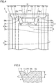
- Fig. 5 illustrates a cross-section that passes through tip 26b of second protruding portion 12b and is perpendicular to the direction in which front cutting edge 7 extends.
- Fig. 6 illustrates a cross-section that passes through an intermediate position between tip 26a of first protruding portion 12a and tip 26b of second protruding portion 12b and is perpendicular to the direction in which front cutting edge 7 extends.
- a value obtained by dividing a height y from the lowest position of second protruding portion 12b to the deepest portion 23c of chip breaker recess 10 by a depth H of chip breaker recess 10 at the deepest portion 23c is, for example, 0.3 or more and less than 1.0.
- a value obtained by dividing height y by depth H may be 0.5 or more and less than 1.0. It should be noted that the lowest position of protruding portion 12 does not need to be tip 26a, 26b of protruding portion 12. The lowest position of protruding portion 12 may be located between tip 26a, 26b of protruding portion 12 and an upper end 29a, 29b of protruding portion 12 (see Fig. 4 ). It should be noted that upper end 29a, 29b of protruding portion 12 is a tip of the upper surface portion of protruding portion 12 extending along upper surface 4.
- the structure of a cutting insert according to Embodiment 3 differs from the structure of the cutting insert according to Embodiment 1 mainly in that the front breaker wall surface portion is formed of a plurality of projections and each of the pair of lateral breaker wall surface portions is formed of recesses and protrusions alternately arranged parallel to a corresponding one of the pair of lateral cutting edges, and is substantially similar to the structure of the cutting insert according to Embodiment 1 in other respects.
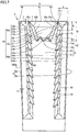
- front breaker wall surface portion 24c of cutting insert 30 is formed of a plurality of projections 15.
- Each of projections 15 projects, for example, from upper surface 4 toward front cutting edge 7.
- the width of each of projections 15 in the direction in which front cutting edge 7 extends decreases as closer to front cutting edge 7.
- the number of projections 15 is, for example, two, and may be three or more.
- a height F of each of projections 15 in a direction perpendicular to the direction in which front cutting edge 7 extends is, for example, 0.1 mm or more and 0.5 mm or less.
- an upper limit of height F of each of projections 15 is not particularly limited, it may be, for example, 0.35 mm.
- a lower limit of height F of each of projections 15 is not particularly limited, it may be, for example, 0.15 mm.
- Height F of projection 15 is, for example, a distance from the tip of the upper end surface of projection 15 to a boundary of front edge portion 31.
- each of a pair of lateral breaker wall surface portions 24a and 24b may be formed of recesses 33 and protrusions 34 alternately arranged parallel to a corresponding one of the pair of lateral cutting edges 8a and 8b.
- the direction in which recesses 33 and protrusions 34 are arranged alternately may not be parallel to the direction in which lateral cutting edges 8a and 8b extend and may be shifted a little from the parallel state, as long as similar effects can be achieved.
- Recesses 33 and protrusions 34 may be pointed or rounded.
- the shapes of recess 33 and protrusion 34 may be triangular or rectangular in plan view.
- a distance D from front breaker wall surface portion 24c to front land surface portion 9c in the direction perpendicular to the direction in which front cutting edge 7 extends may be, for example, 0.3 mm or more and 1.5 mm or less.
- an upper limit of distance D is not particularly limited, it may be, for example, 1.1 mm.
- a lower limit of distance D is not particularly limited, it may be, for example, 0.7 mm.
- Distance D is, for example, a distance from front edge portion 31, which is a boundary between front breaker wall surface portion 24c and upper surface 4, to a boundary between front land surface portion 9c and front rake face 11c.
- Each of the pair of protruding portions 12 has a corresponding one of a pair of straight portions 30a and 30b parallel to a corresponding one of the pair of lateral cutting edges 8a and 8b.
- first protruding portion 12a has first straight portion 30a parallel to first lateral cutting edge 8a.
- second protruding portion 12b has second straight portion 30b parallel to second lateral cutting edge 8b.
- Each of the pair of straight portions 30a and 30b is located on the front cutting edge 7 side.
- a length B of each of the pair of straight portions (first straight portion 30a and second straight portion 30b) is, for example, 0.15 mm or more and 0.5 mm or less.
- an upper limit of length B is not particularly limited, it may be, for example, 0.40 mm.
- a lower limit of length B is not particularly limited, it may be, for example, 0.25 mm. It should be noted that the direction in which the pair of straight portions 30a and 30b extend may not be parallel to the direction in which the pair of lateral cutting edges 8a and 8b extend and may be shifted a little from the parallel state, as long as similar effects can be achieved.
- a spacing A between each of the pair of protruding portions 12a and 12b and a corresponding one of the pair of lateral land surface portions 9a and 9b in the direction perpendicular to the direction in which a corresponding one of the pair of lateral cutting edges 8 extends is, for example, 0.15 mm or more and 0.7 mm or less.
- spacing A is a spacing between straight portion 30a of first protruding portion 12a and a boundary between first lateral land surface portion 9a and first rake face portion 11a.
- spacing A is a spacing between straight portion 30b of second protruding portion 12b and a boundary between second lateral land surface portion 9b and second rake face portion 11b.
- an upper limit of spacing A is not particularly limited, it may be, for example, 0.50 mm.
- a lower limit of spacing A is not limited, it may be, for example, 0.20 mm.
- a width C of each of the pair of lateral land surface portions 9a and 9b in the direction perpendicular to the direction in which a corresponding one of the pair of lateral cutting edges 8a and 8b extends is, for example, 10 ⁇ m or more and 100 ⁇ m or less.
- width C is a width of first lateral land surface portion 9a in the direction perpendicular to the direction in which first lateral cutting edge 8a extends.
- width C is a width of second lateral land surface portion 9b in the direction perpendicular to the direction in which second lateral cutting edge 8b extends.
- an upper limit of width C is not particularly limited, it may be, for example, 50 ⁇ m.
- width J of front land surface portion 9c in the direction perpendicular to the direction in which front cutting edge 7 extends is, for example, 10 ⁇ m or more and 100 ⁇ m or less.
- an upper limit of width J is not particularly limited, it may be, for example, 50 ⁇ m.
- a lower limit of width J is not particularly limited, it may be, for example, 20 ⁇ m.
- a drawing angle ⁇ 1 of each of the pair of protruding portions 12 may be 5° or more and 35° or less.
- the upper surface of first protruding portion 12a has a first straight portion 30a and a first inclined portion 35a opposite to first straight portion 30a.
- First inclined portion 35a is continuous with third inclined surface 27.
- the upper surface of second protruding portion 12b has a second straight portion 30b and a second inclined portion 35b opposite to second straight portion 30b.
- Second inclined portion 35b is continuous with fourth inclined surface 28.
- a drawing angle ⁇ is an angle formed between first straight portion 30a and first inclined portion 35a.
- drawing angle ⁇ is an angle formed between second straight portion 30b and second inclined portion 35b.
- an upper limit of drawing angle ⁇ 1 is not particularly limited, it may be, for example, 25°.
- a lower limit of drawing angle ⁇ is not particularly limited, it may be, for example, 15°.
- an inclination angle ⁇ 2 of rake face 11 to land surface 9 is 15° or more and 45° or less.
- inclination angle ⁇ 2 is an inclination angle of second lateral rake face portion 11b to second lateral land surface portion 9b.
- an upper limit of inclination angle ⁇ 2 is not particularly limited, it may be, for example, 35°.
- a lower limit of inclination angle ⁇ 2 is not particularly limited, it may be, for example, 20°.
- An inclination angle of second lateral rake face portion 11b to second lateral land surface portion 9b may be substantially equal to an inclination angle of first lateral rake face portion 11a to first lateral land surface portion 9a and an inclination angle of front rake face portion 11a to front land surface portion 9c.
- maximum depth H of chip breaker recess 10 is, for example, 60 ⁇ m or more and 200 ⁇ m or less.
- Maximum depth H of chip breaker recess 10 is, for example, a distance between second bottom surface 23b and second lateral land surface portion 9b in the direction perpendicular to upper surface 4.
- an upper limit of maximum depth H is not particularly limited, it may be, for example, 150 ⁇ m.
- a lower limit of maximum depth H is not particularly limited, it may be, for example, 100 ⁇ m.
- the pair of protruding portions 12 are provided to extend from front edge portion 31 toward front cutting edge 7.
- a portion of chip breaker recess 10 located between the pair of protruding portions 12 allows a chip to be divided into short pieces in grooving.
- a portion of chip breaker recess 10 located between each of the pair of protruding portions 12 and a corresponding one of the pair of lateral side surfaces 6 allows a chip to be divided into short pieces in cross-feeding. Consequently, a chip can be divided into short pieces when grooving and cross-feeding are performed on, for example, a workpiece having high toughness, such as aluminum alloy.
- a decrease in machining accuracy, which is caused when a workpiece is cut with a chip twisted therearound, can thus be minimized. Also, the interruption of cutting due to a chip twisted around the workpiece can be prevented or reduced. As a result, cutting can be automated.
- each of the pair of protruding portions 12 is continuous with land surface 9.
- a ratio of a lapped surface is higher than when the protruding portion and the land surface are apart from each other.
- a value (G/L ratio) obtained by dividing sum G of length X1 of boundary 33b between protruding portion 12b, which is one of the pair of protruding portions 12, and land surface 9 and length X2 of boundary 33a between protruding portion 12a, which is the other of the pair of protruding portions 12, and land surface 9 by length L of front cutting edge 7 may be 0.1 or less. This reduces a curl diameter of a chip, allowing the chip to have a spiral shape. Consequently, damage to the machined wall surface, which is caused by a chip contacting the machined wall surface, can be prevented or reduced.
- each of the pair of protruding portions 12 is apart from land surface 9.
- a cutting fluid can be supplied to the blade tip more efficiently than when the protruding portion and the land surface are continuous with each other.
- a lubricating effect of the blade tip can thus be obtained efficiently. Consequently, especially when a material containing a hard substance such as silicon (Si) among aluminums and aluminum alloys is cut, the lubricating effect of the blade tip can be obtained efficiently.
- a value obtained by dividing height y from the lowest position 26b of each of the pair of protruding portions to the deepest portion 23c of chip breaker recess 10 by depth H of chip breaker recess 10 at the deepest portion 23c is 0.3 or more and less than 1.0. This can reduce a chip length.
- a spacing between the pair of protruding portions 12 may decrease as apart from front cutting edge 7.
- the breaker wall surface may be sandwiched between the pair of protruding portions 12 and have front breaker wall surface portion 24c continuous with front edge portion 31.
- distance D from front breaker wall surface portion 24c to land surface 9 in the direction perpendicular to the direction in which front cutting edge 7 extends may be 0.3 mm or more and 1.5 mm or less. This reduces the curl diameter of a chip, allowing the chip to have a spiral shape. Consequently, damage to the machined wall surface, which is caused by a chip contacting the machined wall surface, can be prevented or reduced.
- front breaker wall surface portion 24c may be formed of projections 15. This reduces a contact area between the chip and the front breaker wall surface portion, reducing cutting resistance.
- height F of each of projections 15 in the direction perpendicular to the direction in which front cutting edge 7 extends may be 0.1 mm or more and 0.5 mm or less. This reduces the curl diameter of a chip, allowing the chip to have a spiral shape. Also, the occurrence of chipping at the tip of the projection can be prevented or reduced.
- land surface 9 may have the pair of lateral land surface portions 9a and 9b each continuous with a corresponding one of the pair of lateral side surfaces 6.
- spacing A between each of the pair of protruding portions 12a and 12b and a corresponding one of the pair of lateral land surface portions 9a and 9b in the direction perpendicular to the direction in which lateral cutting edge 8 extends is 0.15 mm or more and 0.7 mm or less. The length of a chip can accordingly be reduced.
- width C of each of the pair of lateral land surface portions 9a and 9b in the direction perpendicular to the direction in which a corresponding one of the pair of lateral cutting edges 8a and 8b extends may be 10 ⁇ m or more and 100 ⁇ m or less.
- the length of a chip can accordingly be reduced.
- the wear amount of a flank face can be reduced while preventing or reducing the occurrence of chipping at the blade tip.
- land surface 9 may have front land surface portion 9a continuous with front side surface 5.
- width J of front land surface portion 9c in the direction perpendicular to the direction in which front cutting edge 7 extends may be 10 ⁇ m or more and 100 ⁇ m or less. This reduces a chip length. Also, a reduction in the wear amount of a flank surface can be reduced while preventing or reducing the occurrence of chipping at the blade tip.
- inclination angle ⁇ 2 of rake face 11 to land surface 9 may be 15° or more and 45° or less.
- the length of a chip can accordingly be reduced.
- the wear amount of a flank face can be reduced while preventing or reducing the occurrence of chipping at the blade tip.
- maximum depth H of chip breaker recess 10 may be 60 ⁇ m or more and 200 ⁇ m or less.
- the length of a chip can accordingly be reduced.
- the wear amount of a flank face can be reduced while preventing or reducing the occurrence of chipping at the blade tip.
- drawing angle ⁇ 1 of each of the pair of protruding portions 12 may be 5° or more and 35° or less. This reduces the curl diameter of a chip, allowing the chip to have a spiral shape. Also, a decrease in the quality of a wall surface of a machined groove can be prevented or reduced.
- the breaker wall surface may have the pair of lateral breaker wall surface portions 24a and 24b each facing a corresponding one of the pair of lateral cutting edges.
- Each of the pair of lateral breaker wall surface portions 24a and 24b may be formed of recesses and protrusions alternately arranged parallel to a corresponding one of the pair of lateral cutting edges. This reduces a contact area between a chip and a lateral breaker wall surface portion, reducing a cutting resistance.
- each of the pair of protruding portions 12 has a corresponding one of the pair of straight portions 30a and 30b which is parallel to a corresponding one of the pair of lateral cutting edges 8, and length B of each of the pair of straight portions 30a and 30b may be 0.15 mm or more and 0.5 mm or less. The wear amount of a flank face can accordingly be reduced while reducing a chip length.
- a workpiece was grooved with cutting insert 30.
- Cutting insert 30 is fixed to a holding member 40.
- the feed direction of cutting insert 30 is a direction perpendicular to the rotation axis of a workpiece.
- a workpiece was an aluminum alloy A6061 having a cylindrical shape.
- the size of the workpiece was a diameter of 30 mm by a length of 60 mm.
- a cutting method was grooving.
- a cutting manner was wet cutting.
- a cutting distance was 200 m.
- the peripheral surface speed of a workpiece was 180 m/min. Grooving was performed for the entire groove width.
- a tool grooving depth was 8 mm in diameter.
- a tool feed speed was 0.07 mm/rev.
- the tool was a polycrystalline diamond (PCD) multi-function tool having a groove width of 2 mm by a lateral cutting edge length of 4.5 mm.
- PCD refers to sintered polycrystalline diamond obtained by sintering diamond particles at high temperature and high pressure.
- the multi-function tool refers to a tool that can be used for both of grooving and cross-feeding.
- the material for the tool was a polycrystalline hard sintered compact containing 90 vol% of diamond having an average particle size of 0.5 ⁇ m.
- the holder model number was SGWR1212.
- a width (C) of the land surface was 0.03 mm.
- a maximum depth (H) of a recess was 100 ⁇ m.
- a distance (A) was 0.2 mm.
- a distance (D) was 0.5 mm.
- a projection height (F) was 0.15 mm.
- An inclination angle ( ⁇ 2) of the rake face was 25°.
- a drawing angle ( ⁇ 1) was 10°.
- Sample No. Total length (G)/length (L) of front cutting edge Length (X1) of boundary (mm) Length (X2) of boundary (mm) Curl diameter of chip (mm) (chip state) 1A 0.02 0.02 0.02 less than 10 (spiral) 1B 0.05 0.05 0.05 less than 10 (spiral) 1C 0.10 0.1 0.1 less than 10 (spiral) 1D 0.15 0.15 0.15 30 to 50 (irregular)
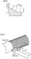
- the curl diameter of a chip was 10 mm or less, and the chip state was spiral. As illustrated in Fig. 11 , a spiral chip gradually becomes larger from a state with a very small curl diameter and is divided at some midpoint thereof. In contrast, when the cutting insert with sample number 1D was used, the curl diameter of a chip was 30 to 50 mm, and the chip state was irregular. As illustrated in Fig. 12 , for example, a certain irregular chip has a large curl diameter, and accordingly, is highly likely to wind around a workpiece. As illustrated in Fig. 13 , for example, another irregular chip fails to curl up neatly and looks clogged, and is highly likely to wind around a workpiece.
- outside-diameter cross-feeding was performed on a workpiece with cutting insert 30.
- the feed direction of cutting insert 30 is a direction parallel to the rotation axis of a workpiece.
- a workpiece was an aluminum alloy A6061 having a cylindrical shape.
- the size of the workpiece was a diameter of 10 mm by a length of 40 mm.
- a cutting method was outside-diameter cross-feeding.
- a cutting manner was wet cutting.
- a cutting distance was 200 m.
- the peripheral surface speed of a workpiece was 250 m/min.
- a tool cutting depth was 0.15 mm.
- a tool feed speed was 0.07 mm/rev.
- the tool was a PCD multi-function tool having a groove width of 2 mm by a lateral cutting edge length of 4.5 mm.
- the material for the tool was a polycrystalline hard sintered compact containing 90 vol% of diamond having an average particle size of 0.5 ⁇ m.
- the holder model number was SGWR1212.
- a width (C) of the land surface was 0.03 mm.
- a distance (A) was 0.4 mm.
- a distance (D) was 0.85 mm.
- a projection height (F) was 0.15 mm.
- An inclination angle ( ⁇ 2) of the rake face was 25°.
- a drawing angle ( ⁇ 1) was 15°.
- the chip length was 50 to 120 mm or less.
- the chip length was 30 to 80 mm or less.
- the chip length was 250 to 350 mm or less. It is considered that a y/H ratio smaller than 0.3 fails to provide a chip with a distortion large enough to divide the chip, resulting in a longer chip. The above results confirmed that setting the y/H ratio of a cutting insert to 0.3 or more can effectively reduce a chip length.
- outside-diameter cross-feeding was performed on a workpiece with cutting insert 30.
- cutting insert 30 was fed parallel to the rotation axis of a workpiece, and is subsequently fed perpendicular to the rotation axis of the workpiece. Such feeding was repeated.
- a workpiece was an aluminum alloy A6061 having a cylindrical shape.
- the size of the workpiece was a diameter of 10 mm by a length of 3000 mm.
- a cutting method was outside-diameter cross-feeding.
- a cutting manner was wet cutting.
- a cutting distance was 1,000 m.
- the peripheral surface speed of a workpiece was 250 m/min.
- Tool cutting depths were 0.1 mm and 1.5 mm. Grooves having a small cutting depth (0.1 mm) and grooves having a great cutting depth (1.5 mm) were processed alternately.
- the pitch of each of the grooves with a small cutting depth and the grooves with a great cutting depth was 10 mm.
- a tool feed speed was 0.07 mm/rev.
- the tool was a PCD multi-function tool having a groove width of 2 mm by a lateral cutting edge length of 4.5 mm.
- the material for the tool was a polycrystalline hard sintered compact containing 90 vol% of diamond having an average particle size of 0.5 ⁇ m.
- the holder model number was SGWR1212.
- a width (C) of the land surface was 0.03 mm.
- a maximum depth (H) of a recess was 100 ⁇ m.
- a distance (A) was 0.4 mm.
- a distance (D) was 0.85 mm.
- a projection height (F) was 0.15 mm.
- An inclination angle ( ⁇ 2) of the rake face was 25°.
- a drawing angle ( ⁇ 1) was 15°.
- a chip length was 300 mm or more.
- the length of the straight portion is as small as about 0.05 mm, in the processing with a cutting depth of 0.1 mm, the lateral breaker wall surface portion has a recessed shape, and accordingly, a substantial breaker width increases, so that a chip cannot be divided into short pieces. Also, it is conceivable that in the processing with a cutting depth of 1.5 mm, an area for contact with a chip is excessively small, thus reducing the stability of a chip.
- the wear amount of a flank face becomes greater than when another cutting insert was used.
- the length of a straight portion becomes as large as about 0.60 mm, the following is conceivable. An effect of reducing a chip contact area cannot be obtained sufficiently, and a cutting fluid cannot be supplied sufficiently to the blade tip, so that a chip length meaning a tool life is poorer than when another cutting insert was used.
- the above results confirmed that setting the length (B) of the straight portion of the cutting insert to 0.15 mm or more can effectively reduce a chip length. Also, it was confirmed that setting the length (B) of the straight portion of the cutting insert to 0.50 mm or less can effectively reduce the wear amount of a flank face.
- a workpiece was grooved with cutting insert 30.
- the feed direction of cutting insert 30 is a direction perpendicular to the rotation axis of the workpiece.
- a workpiece was an aluminum alloy A5056 having a cylindrical shape.
- the size of the workpiece was a diameter of 20 mm by a length of 60 mm.
- a cutting method was grooving.
- a cutting manner was wet cutting.
- a cutting distance was 200 m.
- the peripheral surface speed of a workpiece was 350 m/min. Grooving was performed for the entire groove width.
- the grooving depth was 10 mm in diameter.
- a tool feed speed was 0.12 mm/rev.
- the tool was a PCD multi-function tool having a groove width of 2.5 mm by a lateral cutting edge length of 6.0 mm.
- the material for the tool was a polycrystalline hard sintered compact containing 90 vol% of diamond having an average particle size of 0.5 ⁇ m.
- the holder model number was SGWR1212.
- a width (C) of the land surface was 0.07 mm.
- a maximum depth (H) of a recess was 100 ⁇ m.
- a distance (A) was 0.4 mm.
- a projection height (F) was 0.1 mm.
- An inclination angle ( ⁇ 2) of the rake face was 25°.
- a drawing angle ( ⁇ 1) was 15°.
- the curl diameter of a chip was 50 mm or more, and the chip state was irregular.
- the cutting insert with sample number 4A the following is conceivable. Since a chip overlaps onto the upper surface of the edge portion due to an excessively small breaker width, it is difficult to control the chip.
- the cutting insert with sample number 4F the curl diameter of a chip was 30 to 50 mm, and the chip state was is irregular.
- the cutting insert with sample number 4F was used, the following is conceivable. Since the breaker width is excessively large, the chip does not contact the front breaker wall surface, and the chip accordingly cannot be controlled stably, so that irregular curling is exhibited.
- a workpiece was grooved with cutting insert 30.
- the feed direction of cutting insert 30 is a direction perpendicular to the rotation axis of the workpiece.
- a workpiece was an aluminum alloy ADC12 having a cylindrical shape.
- the size of the workpiece was a diameter of 50 mm by a length of 50 mm.
- a cutting method was grooving.
- a cutting manner was wet cutting.
- a cutting distance was 150 m.
- the peripheral surface speed of a workpiece was 400 m/min. Grooving was performed for the entire groove width.
- a tool grooving depth was 6 mm in diameter.
- a tool feed speed was 0.07 mm/rev.
- the tool was a PCD multi-function tool having a groove width of 2.5 mm by a lateral cutting edge length of 4.5 mm.
- the material for the tool was a polycrystalline hard sintered compact containing 90 vol% of diamond having an average particle size of 0.5 ⁇ m.
- the holder model number was SGWR1212.
- a width (C) of the land surface was 0.03 mm.
- a maximum depth (H) of a recess was 100 ⁇ m.
- a distance (A) was 0.4 mm.
- a distance (D) was 0.85 mm.
- An inclination angle ( ⁇ 2) of the rake face was 25°.
- a drawing angle ( ⁇ 1) was 15°.
- the curl diameter of a chip was 50 mm or more, and the chip state was irregular. Also, the projection portion and its periphery were welded.
- the cutting insert with sample number 5A was used, the following is conceivable. Since the projection height is excessively small, the chip contacts the entire front breaker wall surface portion, and it is difficult to supply a cutting fluid to the blade tip. This increase a cutting resistance, leading to welding.
- the cutting insert with sample number 5F was used, the curl diameter of a chip was 30 to 50 mm, and the chip state was irregular. Also, the tip of the projection was chipped. When the cutting insert with sample number 5F was used, the following is conceivable. The tip of the projection becomes sharp to reduce its strength, and the tip is accordingly chipped, which makes it difficult to control the chip.
- outside-diameter cross-feeding was performed on a workpiece with cutting insert 30.
- the feed direction of cutting insert 30 is a direction parallel to the rotation axis of a workpiece.
- a workpiece was an aluminum alloy A2014 having a cylindrical shape.
- the size of the workpiece was a diameter of 20 mm by a length of 50 mm.
- a cutting method was outside-diameter cross-feeding.
- a cutting manner was wet cutting.
- a cutting distance was 200 m.
- the peripheral surface speed of a workpiece was 250 m/min.
- a tool cutting depth was 0.7 mm.
- a tool feed speed was 0.10 mm/rev.
- the tool was a PCD multi-function tool having a groove width of 2.5 mm by a lateral cutting edge length of 4.5 mm.
- the material for the tool was a polycrystalline hard sintered compact containing 90 vol% of diamond having an average particle size of 0.5 ⁇ m.
- the holder model number was SGWR1212.
- a width (C) of the land surface was 0.03 mm.
- a maximum depth (H) of a recess was 100 ⁇ m.
- a distance (D) was 0.85 mm.
- a projection height (F) was 0.25 mm.
- An inclination angle ( ⁇ 2) of the rake face was 25°.
- a drawing angle ( ⁇ 1) was 15°.
- outside-diameter cross-feeding was performed on a workpiece with cutting insert 30.
- the feed direction of cutting insert 30 is a direction parallel to the rotation axis of a workpiece.
- a workpiece was an aluminum alloy A6061 having a cylindrical shape.
- the size of the workpiece was a diameter of 10 mm by a length of 40 mm.
- a cutting method was outside-diameter cross-feeding.
- a cutting manner was wet cutting.
- a cutting distance was 200 m.
- the peripheral surface speed of a workpiece was 200 m/min.
- a tool cutting depth was 1.0 mm.
- a tool feed speed was 0.15 mm/rev.
- the tool was a PCD multi-function tool having a groove width of 2.5 mm by a lateral cutting edge length of 4.5 mm.
- the material for the tool was a polycrystalline hard sintered compact containing 90 vol% of diamond having an average particle size of 0.5 ⁇ m.
- the holder model number was SGWR1212.
- a maximum depth (H) of the land surface was 100 ⁇ m.
- a depth (D) was 1.0 mm.
- a projection height (F) was 0.2 mm.
- An inclination angle ( ⁇ 2) of the rake face was 25°.
- a drawing angle ( ⁇ 1) was 15°.
- Width of lateral land surface portion (C) ( ⁇ m) Chip length (mm)
- outside-diameter cross-feeding was performed on a workpiece with cutting insert 30.
- the feed direction of cutting insert 30 is a direction parallel to the rotation axis of a workpiece.
- a workpiece was an aluminum alloy A6061 having a cylindrical shape.
- the size of the workpiece was a diameter of 30 mm by a length of 60 mm.
- a cutting method was outside-diameter cross-feeding.
- a cutting manner was wet cutting.
- a cutting distance was 200 m.
- the peripheral surface speed of a workpiece was 500 m/min.
- a tool cutting depth was 0.5 mm.
- a tool feed speed was 0.08 mm/rev.
- the tool was a PCD multi-function tool having a groove width of 2.5 mm by a lateral cutting edge length of 4.5 mm.
- the material for the tool was a polycrystalline hard sintered compact containing 90 vol% of diamond having an average particle size of 0.5 ⁇ m.
- the holder model number was SGWR1212.
- a width (C) of the land surface was 0.03 mm.
- a maximum depth (H) of the recess was 150 ⁇ m.
- a distance (A) was 0.4 mm.
- a distance (D) was 0.85 mm.
- a projection height (F) was 0.15 mm.
- a drawing angle ( ⁇ 1) was 15°.
- a chip length was 200 to 300 mm, and a flank face wear amount was 0.019 mm.
- the cutting insert with sample number 8A the following is conceivable. Since the breaker depth gradually decreases as a rake angle decreases with a constant breaker width, a sufficient recess space into which a chip flows cannot be obtained, so that the chip cannot be divided into short pieces.
- the cutting insert with sample number 8F a chip length was 150 to 300 mm, and a flank face wear amount was 0.051 mm.
- the blade tip was chipped.
- the cutting insert with sample number 8F the following is conceivable. Since the blade tip becomes sharp whereas its strength decreases, a chip cannot be controlled normally due to the occurrence of chipping at the blade tip. which makes it difficult to normally control a chip due to chipping at the blade tip.
- outside-diameter cross-feeding was performed on a workpiece with cutting insert 30.
- the feed direction of cutting insert 30 is a direction parallel to the rotation axis of a workpiece.
- a workpiece was an aluminum alloy A6061 having a cylindrical shape.
- the size of the workpiece was a diameter of 20 mm by a length of 60 mm.
- a cutting method was outside-diameter cross-feeding.
- a cutting manner was wet cutting.
- a cutting distance was 200 m.
- the peripheral surface speed of a workpiece was 300 m/min.
- a tool cutting depth was 0.7 mm.
- a tool feed speed was 0.10 mm/rev.
- the tool was a PCD multi-function tool having a groove width of 2.5 mm by a lateral cutting edge length of 4.5 mm.
- the material for the tool was a polycrystalline hard sintered compact containing 90 vol% of diamond having an average particle size of 0.5 ⁇ m.
- the holder model number was SGWR1212.
- a width (C) of the land surface was 0.03 mm.
- a distance (A) was 0.6 mm.
- a distance (D) was 0.85 mm.
- a projection height (F) was 0.15 mm.
- An inclination angle ( ⁇ 2) of the rake face was 25°.
- a drawing angle ( ⁇ 1) was 15°.
- a workpiece was grooved with cutting insert 30.
- the feed direction of cutting insert 30 is a direction perpendicular to the rotation axis of a workpiece.
- a workpiece was an aluminum alloy A6061 having a cylindrical shape.
- the size of the workpiece was a diameter of 30 mm by a length of 60 mm.
- a cutting method was grooving.
- a cutting manner was wet cutting.
- a cutting distance was 200 m.
- the peripheral surface speed of a workpiece was 250 m/min.
- a tool cutting depth was 8 mm in diameter.
- a tool feed speed was 0.07 mm/rev.
- the tool was a PCD multi-function tool having a groove width of 2.5 mm by a lateral cutting edge length of 4.5 mm.
- the material for the tool was a polycrystalline hard sintered compact containing 90 vol% of diamond having an average particle size of 0.5 ⁇ m.
- the holder model number was SGWR1212.
- a width (C) of the land surface was 0.03 mm.
- a maximum depth (H) of a recess was 10 ⁇ m.
- a distance (A) was 0.4 mm.
- a distance (D) was 0.85 mm.
- a projection height (F) was 0.15 mm.
- An inclination angle ( ⁇ 2) of the rake face was 25°.
- the curl diameter of a chip was 10 mm or less, and the chip state was spiral.
- a flow and gouge were caused on the wall surface of a machined groove.
- the chip curves less due to drawing, and a flow or gouge was caused by rubbing the machined wall surface.
- the cutting insert with sample number 10F was used, the curl diameter of a chip was 30 to 50 mm, and the chip state was irregular. Also, a flow and gouge were caused on the wall surface of the machined groove.
- the cutting insert with sample number 10F was used, the following is conceivable. An excessively high drawing effect inhibits a flow of a chip, which may cause clogging or welding of the chip.
- first lateral rake face portion 11a is continuous with first lateral breaker wall surface portion 24a via first bottom surface 23a
- second lateral rake face portion 11b is continuous with second lateral breaker wall surface portion 24b via second bottom surface 23b
- front rake face portion 11c is continuous with front breaker wall surface portion 24c via third bottom surface 23c
- edge portion 2 may not have any one of first bottom surface 23a, second bottom surface 23b, and third bottom surface 23c.
- first lateral rake face portion 11a may be directly continuous with first lateral breaker wall surface portion 24a.
- Second lateral rake face portion 11b may be directly continuous with second lateral breaker wall surface portion 24b.
- Front rake face portion 11c may be directly continuous with front breaker wall surface portion 24c.
Landscapes
- Engineering & Computer Science (AREA)
- Mechanical Engineering (AREA)
- Cutting Tools, Boring Holders, And Turrets (AREA)
- Milling Processes (AREA)
Abstract
Description
- The present invention relates to cutting inserts. The present application claims the priority benefit of Japanese Patent Application No.
2016-089268 filed on April 27, 2016 - Japanese Patent Laying-Open No.
2008-272923 - Japanese Patent Laying-Open No.
7-314204 -
- PTL 1: Japanese Patent Laying-Open No.
2008-272923 - PTL 2: Japanese Patent Laying-Open No.
07-314204 - A cutting insert according to an embodiment of the present invention includes a body and an edge portion provided on the body. The edge portion includes an upper surface, a side surface, and a land surface. The side surface has a front side surface and a pair of lateral side surfaces adjacent to the front side surface. An intersection between the land surface and the front side surface form a front cutting edge. An intersection between the land surface and each of the pair of lateral side surfaces forms a corresponding one of a pair of lateral cutting edges. The edge portion contains 80 vol% or more of diamond. A chip breaker recess is provided between the upper surface and the land surface. Surfaces forming the chip breaker recess include a rake face continuous with the land surface and a breaker wall surface continuous with the upper surface. The upper surface has a front edge portion opposite to the front cutting edge from the chip breaker recess. The pair of protruding portions are provided to extend from the front edge portion toward the front cutting edge.
-
-
Fig. 1 is a schematic perspective view illustrating the structure of a cutting insert according to Embodiment 1. -
Fig. 2 is a schematic plan view illustrating the structure of an edge portion of the cutting insert according to Embodiment 1. -
Fig. 3 is a schematic cross-sectional view taken along line III-III inFig. 2 . -
Fig. 4 is a schematic plan view showing the structure of an edge portion of a cutting insert according toEmbodiment 2. -
Fig. 5 is a schematic cross-sectional view taken along line V-V inFig. 4 . -
Fig. 6 is a schematic cross-sectional view taken along line VI-VI inFig. 4 . -
Fig. 7 is a schematic plan view illustrating the structure of an edge portion of a cutting insert according to Embodiment 3. -
Fig. 8 is a schematic cross-sectional view taken along line VIII-VIII inFig. 7 . -
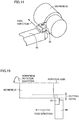
Fig. 9 is a schematic perspective view illustrating how to groove a workpiece. -
Fig. 10 is a schematic plan view illustrating how to groove a workpiece. -
Fig. 11 shows a spiral chip. -
Fig. 12 shows a first example of an irregular chip. -
Fig. 13 shows a second example of an irregular chip. -
Fig. 14 is a schematic perspective view illustrating how to cross-feed a workpiece. -
Fig. 15 is a schematic plan view illustrating how to cross-feed a workpiece. -
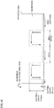
Fig. 16 is a schematic plan view illustrating an example of tooling of cross-feed. - The material for the breaker wall of the cutting insert described in Japanese Patent Laying-Open No.
07-314204 - An object of an aspect of the present invention is to provide a cutting tool capable of dividing a chip in both of grooving and cross-feeding.
- According to an aspect of the present invention, a cutting tool capable of dividing a chip in both of grooving and cross-feeding can be provided.
- A summary of embodiments of the present invention will now be described.
- (1) A cutting insert 30 according to an aspect of the present invention includes a body 1 and an
edge portion 2 provided on body 1.Edge portion 2 includes anupper surface 4, aside surface 32, and aland surface 9.Side surface 32 has afront side surface 5 and a pair oflateral side surfaces 6 adjacent tofront side surface 5. An intersection betweenland surface 9 andfront side surface 5 forms afront cutting edge 7. An intersection betweenland surface 9 and each of the pair oflateral side surfaces 6 forms a corresponding one of a pair oflateral cutting edges 8.Edge portion 2 contains 80 vol% or more of diamond. Achip breaker recess 10 is provided betweenupper surface 4 andland surface 9. The surfaces forming chip breaker recess 10 include a rake face 11 continuous with the land surface and abreaker wall surface 24 continuous withupper surface 4.Upper surface 4 has afront edge portion 31 opposite tofront cutting edge 7 from chip breaker recess 10. A pair of protrudingportions 12 are provided to extend fromfront edge portion 31 towardfront cutting edge 7.
In cutting insert 30 according to above (1), the pair of protrudingportions 12 are provided to extend fromfront edge portion 31 towardfront cutting edge 7. The portion ofchip breaker recess 10 between the pair of protrudingportions 12 allows a chip to be divided into short pieces in grooving. The portion ofchip breaker recess 10 located between each of the pair of protrudingportions 12 and a corresponding one of the pair of lateral side surfaces 6 allows a chip to be divided into short pieces in cross-feeding. Consequently, a chip can be divided into short pieces when grooving and cross-feeding are performed on, for example, a workpiece having high toughness, such as aluminum alloy. A decrease in machining accuracy, which is caused when a workpiece is cut with a chip twisted therearound, can thus be minimized. Also, the interruption of cutting due to a chip twisted around the workpiece can be prevented or reduced. As a result, cutting can be automated. - (2) In cutting
insert 30 according to above (1), each of the pair of protrudingportions 12 may be continuous withland surface 9. When the protruding portion and the land surface are continuous with each other, a ratio of a lapped surface (the lapped surface will be described below in detail) is higher than when the protruding portion and the land surface are apart from each other. Thus, welding of the blade tip can be reduced effectively during grooving. Welding of the blade tip can be reduced effectively especially when a material having high toughness among aluminums and aluminum alloys is used. - (3) In cutting
insert 30 according to above (2), a value (G/L ratio) obtained by dividing a sum G of a length XI of aboundary 33b between onerib 12b of the pair of protrudingportions 12 andland surface 9 and a length X2 of aboundary 33a between theother rib 12a of the pair of protrudingportions 12 andland surface 9 by a length L offront cutting edge 7 may be 0.1 or less. This reduces a curl diameter of a chip, allowing the chip to have a spiral shape. Consequently, damage to the machined wall surface, which is caused by a chip contacting the machined wall surface, can be prevented or reduced. - (4) In cutting
insert 30 according to above (1), each of the pair of protrudingportions 12 may be apart fromland surface 9. When the protruding portion and the land surface are apart from each other, a cutting fluid is supplied to the blade tip more efficiently than when the protruding portion and the land surface are continuous with each other. A lubricating effect of the blade tip can thus be obtained efficiently. Consequently, especially when a material containing a hard substance such as silicon (Si) among aluminums and aluminum alloys is cut, the lubricating effect of the blade tip can be obtained efficiently. - (5) In cutting
insert 30 according to above (4), in a cross-section that passes through atip 29b of each of the pair of protrudingportions 12 and is perpendicular to the direction in whichfront cutting edge 7 extends, a value obtained by dividing a height y from alowest position 26b of each of the pair of protruding portions to adeepest portion 23c ofchip breaker recess 10 by a depth H ofchip breaker recess 10 atdeepest portion 23c may be 0.3 or more and less than 1.0. This can reduce a chip length. - (6) In cutting
insert 30 according to any one of above (1) to (5), a spacing between the pair of protrudingportions 12 may decrease as apart fromfront cutting edge 7. - (7) In cutting
insert 30 according to any one of above (1) to (6), the breaker wall surface may have a front breakerwall surface portion 24c that is sandwiched between the pair of protrudingportions 12 and is continuous withfront edge portion 31. In plan view, a distance D from front breakerwall surface portion 24c to landsurface 9 in the direction perpendicular to the direction in whichfront cutting edge 7 extends may be 0.3 mm or more and 1.5 mm or less. This reduces the curl diameter of a chip, allowing the chip to have a spiral shape. Consequently, damage to the machined wall surface, which is caused by a chip contacting the machined wall surface, can be prevented or reduced. - (8) In cutting
insert 30 according to above (7), front breakerwall surface portion 24c may be formed of a plurality ofprojections 15. This reduces a contact area between a chip and the front breaker wall surface portion, reducing cutting resistance. - (9) In cutting
insert 30 according to above (8), in plan view, a height F of each ofprojections 15 in the direction perpendicular to the direction in whichfront cutting edge 7 extends may be 0.1 mm or more and 0.5 mm or less. This reduces the curl diameter of a chip, allowing the chip to have a spiral shape. Also, the occurrence of chipping at the tip of the projection can be prevented or reduced. - (10) In cutting
insert 30 according to any one of above (1) to (9),land surface 9 may have a pair of lateralland surface portions portions land surface portions lateral cutting edge 8 extends is 0.15 mm or more and 0.7 mm or less. The length of a chip can accordingly be reduced. - (11) In cutting
insert 30 according to above (10), in plan view, a width C of each of the pair of lateralland surface portions lateral cutting edges 8a extends may be 10 µm or more and 100 µm or less. The length of a chip can accordingly be reduced. Also, the wear amount of a flank face can be reduced while preventing or reducing the occurrence of chipping at the blade tip. - (12) In cutting
insert 30 according to any one of above (1) to (11),land surface 9 may have a frontland surface portion 9c continuous withfront side surface 5. In plan view, a width J of frontland surface portion 9c in the direction perpendicular to the direction in whichfront cutting edge 7 extends may be 10 µm or more and 100 µm or less. The length of a chip can accordingly be reduced Also, the wear amount of a flank face can be reduced while preventing or reducing the occurrence of chipping at the blade tip. - (13) In cutting
insert 30 according to any one of above (1) to (12), an inclination angle θ2 of rake face 11 to landsurface 9 may be 15° or more and 45° or less. The length of a chip can accordingly be reduced Also, the wear amount of a flank face can be reduced while preventing or reducing the occurrence of chipping at the blade tip. - (14) In cutting
insert 30 according to any one of above (1) above (13), a maximum depth H ofchip breaker recess 10 may be 60 µm or more and 200 µm or less. The length of a chip can accordingly be reduced. Also, the wear amount of a flank face can be reduced while preventing or reducing the occurrence of chipping at the blade tip. - (15) In cutting
insert 30 according to any one of above (1) to (14), in plan view, a drawing angle θ1 of each of the pair of protrudingportions 12 may be 5° or more and 35° or less. This reduces the curl diameter of a chip, allowing the chip to have a spiral shape. Also, a decrease in the quality of a wall surface of a machined groove can be prevented or reduced. - (16) In cutting
insert 30 according to any one of above (1) to (15), the breaker wall surface may have a pair of lateral breakerwall surface portions wall surface portions - (17) In cutting
insert 30 according to above (16), each of the pair of protrudingportions 12 has a corresponding one of a pair ofstraight portions lateral cutting edges 8, and a length B of each of the pair ofstraight portions - (18) In cutting
insert 30 according to above (17), each of the pair ofstraight portions front cutting edge 7 side. - Embodiments of the present invention (hereinafter, each of which is referred to as the present embodiment) will now be described in detail with reference to the drawings. It should be noted that in the following drawings, the same or corresponding parts are denoted by the same reference numerals, and the description thereof will not be repeated.
- First, the structure of a cutting
insert 30 according to Embodiment 1 will be described. - As illustrated in
Fig. 1 , cuttinginsert 30 according to Embodiment 1 mainly includes a body 1 and anedge portion 2.Edge portion 2 is provided on body 1.Edge portion 2 is provided, for example, on a surface of a projecting portion of body 1. Body 1 has, for example, afastening hole 20. The material for body 1 is, for example, cemented carbide or steel. - As illustrated in
Figs. 1 and2 ,edge portion 2 includes anupper surface 4, aside surface 32, and aland surface 9.Side surface 32 mainly has afront side surface 5 and a pair of lateral side surfaces 6 adjacent tofront side surface 5.Edge portion 2 contains 80 vol% or more of diamond.Edge portion 2 is formed of, for example, a diamond sintered compact. Diamond may be polycrystalline diamond or single crystal diamond.Edge portion 2 preferably contains 90 vol% or more, more preferably, 95 vol% or more of diamond. The load onedge portion 2 is relatively high when cross-feeding is performed with a somewhat great cutting depth. Considering the above, the material foredge portion 2 is preferably polycrystalline diamond that is more resistant to chipping than single crystal diamond. The use of single crystal diamond having an increased strength due to the presence of an additive can also effectively prevent or reduce chipping ofedge portion 2. - The surface of
edge portion 2 containing diamond has been lapped with a lapping machine. Lapping refers to smoothing performed enough to achieve a mirror plane. Laser machining performed on this surface forms achip breaker recess 10. Consequently,land surface 9 turns into a lapped surface. The surface roughness ofland surface 9 is, for example, 0.05 µm or more and 0.2 µm or less. Herein, the surface roughness refers to ten point height of irregularities (Rz). As a result, welding of aluminum to landsurface 9 ofedge portion 2 can be prevented or reduced in processing of aluminum. A blade tip (cutting edge) may have been subjected to horning or negative land processing. This increases the strength of the blade tip, which is effective when, for example, chipping is an issue. - An intersection between
land surface 9 andfront side surface 5 formsfront cutting edge 7. An intersection betweenland surface 9 and each of the pair of lateral side surfaces 6 forms a corresponding one of the pair of lateral cutting edges 8. The pair of lateral side surfaces 6 have a firstlateral side surface 6a and a secondlateral side surface 6b opposite to firstlateral side surface 6a. The pair oflateral cutting edges 8 have a firstlateral cutting edge 8a and a secondlateral cutting edge 8b opposite to firstlateral cutting edge 8a. An intersection between firstlateral side surface 6a andland surface 9 forms firstlateral cutting edge 8a. Similarly, an intersection between secondlateral side surface 6b andland surface 9 forms secondlateral cutting edge 8b. - As illustrated in
Fig. 2 ,land surface 9 has a pair of lateral land surface portions (a first lateralland surface portion 9a and a second lateralland surface portion 9b) and a frontland surface portion 9c. Each of the pair ofland surface portions lateral side surface 6a and first lateralland surface portion 9a forms firstlateral cutting edge 8a. An intersection between secondlateral side surface 6b and second lateral land surface forms secondlateral cutting edge 8b. Frontland surface portion 9c is continuous withfront side surface 5. An intersection betweenfront side surface 5 and frontland surface portion 9c formsfront cutting edge 7. -
Chip breaker recess 10 is provided betweenupper surface 4 andland surface 9.Chip breaker recess 10 can be formed by, for example, performing laser processing onedge portion 2. The surfaces formingchip breaker recess 10 include a rake face 11 and abreaker wall surface 24. Rake face 11 is continuous withland surface 9.Breaker wall surface 24 is continuous withupper surface 4. Rake face 11 includes a first lateralrake face portion 11a, a second lateralrake face portion 11b, and a frontrake face portion 11c.Breaker wall surface 24 includes a pair of lateral breaker wall surface portions (a first lateral breakerwall surface portion 24a and a second lateral breakerwall surface portion 24b) and a front breakerwall surface portion 24c. Each of the pair of lateral breakerwall surface portions lateral cutting edges - As illustrated in
Fig. 2 ,chip breaker recess 10 includes afirst recess 10a, asecond recess 10b, and athird recess 10c.First recess 10a is defined by first lateralrake face portion 11a, a firstbottom surface 23a, a first lateral breakerwall surface portion 24a, and a firstinclined surface 22a. In other words, the surfaces formingfirst recess 10a include first lateralrake face portion 11a, firstbottom surface 23a, first lateral breakerwall surface portion 24a, and firstinclined surface 22a. First lateralrake face portion 11a is continuous with first lateralland surface portion 9a. First lateral breakerwall surface portion 24a is continuous withupper surface 4. Firstbottom surface 23a connects first lateral breakerwall surface portion 24a and first lateralrake face portion 11a to each other. Firstinclined surface 22a is continuous with first lateral breakerwall surface portion 24a, firstbottom surface 23a, first lateralrake face portion 11a, and frontland surface portion 9c. -
Second recess 10b is defined by second lateralrake face portion 11b, a secondbottom surface 23b, a second lateral breakerwall surface portion 24b, and a secondinclined surface 22b. In other words, the surfaces formingsecond recess 10b include second lateralrake face portion 11b, secondbottom surface 23b, second lateral breakerwall surface portion 24b, and secondinclined surface 22b. Second lateralrake face portion 11b is continuous with second lateralland surface portion 9b. Second lateral breakerwall surface portion 24b is continuous withupper surface 4. Secondbottom surface 23b connects second lateral breakerwall surface portion 24b and second lateralrake face portion 11b to each other. Secondinclined surface 22b is continuous with second lateral breakerwall surface portion 24b, secondbottom surface 23b, second lateralrake face portion 11b, and frontland surface portion 9c. - As illustrated in
Fig. 3 , the width ofsecond recess 10b in the direction parallel to the direction in whichfront cutting edge 7 extends decreases as apart fromupper surface 4. Secondbottom surface 23b may be substantially parallel toupper surface 4 and second lateralland surface portion 9b. An angle formed between secondbottom surface 23b and second lateral breakerwall surface portion 24b may be greater than 90°. Similarly, an angle formed between secondbottom surface 23b and second lateralrake face portion 11b may be greater than 90°. - As illustrated in
Fig. 2 ,third recess 10c is defined by frontrake face portion 11c, a thirdbottom surface 23c, front breakerwall surface portion 24c, a thirdinclined surface 27, and a fourthinclined surface 28. In other words, the surfaces formingthird recess 10c include frontrake face portion 11c, thirdbottom surface 23c, front breakerwall surface portion 24c, thirdinclined surface 27, and fourthinclined surface 28. Frontrake face portion 11c is continuous with frontland surface portion 9c. Front breakerwall surface portion 24c is continuous withupper surface 4. Thirdbottom surface 23c connects front breakerwall surface portion 24c and frontrake face portion 11c to each other. Thirdinclined surface 27 and fourthinclined surface 28 are continuous with front breakerwall surface portion 24c, thirdbottom surface 23c, and frontrake face portion 11c. Fourthinclined surface 28 is opposite to thirdinclined surface 27 from thirdbottom surface 23c. -
Upper surface 4 is a surface opposite to the surface ofedge portion 2 which is in contact with body 1.Upper surface 4 is provided betweenfirst recess 10a andsecond recess 10b. In other words,first recess 10a is opposite tosecond recess 10b fromupper surface 4.Upper surface 4 has afront edge portion 31 opposite tofront cutting edge 7 fromthird recess 10c ofchip breaker recess 10. Front breakerwall surface portion 24c is sandwiched between the pair of protrudingportions 12 and is continuous withfront edge portion 31. In other words, front breakerwall surface portion 24c is in contact withupper surface 4 atfront edge portion 31.Front edge portion 31 is an intersection between front breakerwall surface portion 24c andupper surface 4. - As illustrated in
Fig. 2 , the pair of protrudingportions 12 are provided to extend fromfront edge portion 31 towardfront cutting edge 7. The pair of protrudingportions 12 are part ofedge portion 2. The pair of protrudingportions 12 include a first protrudingportion 12a and a second protrudingportion 12b. First protrudingportion 12a is located betweenfirst recess 10a andthird recess 10c. In other words,third recess 10c is opposite tofirst recess 10a from first protrudingportion 12a. Second protrudingportion 12b is located betweensecond recess 10b andthird recess 10c. In other words,third recess 10c is opposite tosecond recess 10b from second protrudingportion 12b.Third recess 10c is located between first protrudingportion 12a and second protrudingportion 12b. A spacing between the pair of protrudingportions 12 may decrease as apart fromfront cutting edge 7. - Third
inclined surface 27 and part of first lateral breakerwall surface portion 24a form first protrudingportion 12a. First protrudingportion 12a applies a stress to a chip cut with firstlateral cutting edge 8a by first lateral breakerwall surface portion 24a, thereby dividing the chip. First protrudingportion 12a changes the direction in which a chip advances such that a chip cut withfront cutting edge 7 by thirdinclined surface 27 heads for front breakerwall surface portion 24c. Similarly, fourthinclined surface 28 and part of second lateral breakerwall surface portion 24b form second protrudingportion 12b. Second protrudingportion 12b applies a stress to a chip cut with secondlateral cutting edge 8b by second lateral breakerwall surface portion 24b, thereby dividing the chip. Second protrudingportion 12b changes the direction in which a chip advances such that a chip cut withfront cutting edge 7 by fourthinclined surface 28 heads for front breakerwall surface portion 24c. - As illustrated in
Fig. 2 , each of the pair of protrudingportions 12 may be continuous withland surface 9. Specifically, each of first protrudingportion 12a and second protrudingportion 12b connects frontland surface portion 9c andupper surface 4 to each other. The upper end surface of first protrudingportion 12a is continuous with both of frontland surface portion 9c andupper surface 4. Similarly, the upper end surface of second protrudingportion 12b is continuous with both of frontland surface portion 9c andupper surface 4. - A value obtained by dividing a sum G of a length X1 of a
boundary 33b between second protrudingportion 12b, which is one of the pair of protrudingportions 12, and frontland surface portion 9c and a length X2 of aboundary 33a between first protrudingportion 12a, which is the other of the pair of protrudingportions 12, and frontland surface portion 9c by a length L offront cutting edge 7 is, for example, 0.1 or less. A value obtained by dividing sum G of length X1 and length X2 by length L offront cutting edge 7 may be 0.05 or less or 0.02 or less. In plan view (as seen from a direction perpendicular to upper surface 4), the width of each of the pair of protrudingportions 12 in the direction parallel to the direction in whichfront cutting edge 7 extends may increase as apart from frontland surface portion 9c. - The structure of a cutting insert according to
Embodiment 2 will now be described. The structure of the cutting insert according toEmbodiment 2 differs from the structure of the cutting insert according to Embodiment 1 in that each of a pair of protruding portions is apart from a land surface, and is substantially similar to the structure of the cutting insert according to Embodiment 1 in other respects. - As illustrated in
Fig. 4 , each of the pair of protrudingportions 12 of cuttinginsert 30 according toEmbodiment 2 may be apart fromland surface 9. First protrudingportion 12a and second protrudingportion 12b are separated from frontland surface portion 9c byrecess 10. Thirdinclined surface 27 and part of first lateral breakerwall surface portion 24a form first protrudingportion 12a. Atip 26a of first protrudingportion 12a is an intersection of thirdinclined surface 27, first lateral breakerwall surface portion 24a, and frontrake face portion 11c. Similarly, fourthinclined surface 28 and part of second lateral breakerwall surface portion 24b form second protrudingportion 12b. Atip 26b of second protrudingportion 12b is an intersection of fourthinclined surface 28, second lateral breakerwall surface portion 24b, and frontrake face portion 11c. In the direction perpendicular toupper surface 4,tip 26a of first protrudingportion 12a andtip 26b of second protrudingportion 12b are located lower thanupper surface 4. -
Fig. 5 illustrates a cross-section that passes throughtip 26b of second protrudingportion 12b and is perpendicular to the direction in whichfront cutting edge 7 extends.Fig. 6 illustrates a cross-section that passes through an intermediate position betweentip 26a of first protrudingportion 12a andtip 26b of second protrudingportion 12b and is perpendicular to the direction in whichfront cutting edge 7 extends. As illustrated inFigs. 5 and6 , a value obtained by dividing a height y from the lowest position of second protrudingportion 12b to thedeepest portion 23c ofchip breaker recess 10 by a depth H ofchip breaker recess 10 at thedeepest portion 23c is, for example, 0.3 or more and less than 1.0. A value obtained by dividing height y by depth H may be 0.5 or more and less than 1.0. It should be noted that the lowest position of protrudingportion 12 does not need to betip portion 12. The lowest position of protrudingportion 12 may be located betweentip portion 12 and anupper end Fig. 4 ). It should be noted thatupper end portion 12 is a tip of the upper surface portion of protrudingportion 12 extending alongupper surface 4. - The structure of a cutting insert according to Embodiment 3 will now be described. The structure of the cutting insert according to Embodiment 3 differs from the structure of the cutting insert according to Embodiment 1 mainly in that the front breaker wall surface portion is formed of a plurality of projections and each of the pair of lateral breaker wall surface portions is formed of recesses and protrusions alternately arranged parallel to a corresponding one of the pair of lateral cutting edges, and is substantially similar to the structure of the cutting insert according to Embodiment 1 in other respects.
- As illustrated in
Fig. 7 , front breakerwall surface portion 24c of cuttinginsert 30 according to Embodiment 3 is formed of a plurality ofprojections 15. Each ofprojections 15 projects, for example, fromupper surface 4 towardfront cutting edge 7. The width of each ofprojections 15 in the direction in whichfront cutting edge 7 extends decreases as closer tofront cutting edge 7. The number ofprojections 15 is, for example, two, and may be three or more. - In plan view, a height F of each of
projections 15 in a direction perpendicular to the direction in whichfront cutting edge 7 extends is, for example, 0.1 mm or more and 0.5 mm or less. Although an upper limit of height F of each ofprojections 15 is not particularly limited, it may be, for example, 0.35 mm. Although a lower limit of height F of each ofprojections 15 is not particularly limited, it may be, for example, 0.15 mm. Height F ofprojection 15 is, for example, a distance from the tip of the upper end surface ofprojection 15 to a boundary offront edge portion 31. - As illustrated in
Fig. 7 , each of a pair of lateral breakerwall surface portions recesses 33 andprotrusions 34 alternately arranged parallel to a corresponding one of the pair oflateral cutting edges protrusions 34 are arranged alternately may not be parallel to the direction in whichlateral cutting edges Recesses 33 andprotrusions 34 may be pointed or rounded. The shapes ofrecess 33 andprotrusion 34 may be triangular or rectangular in plan view. - In plan view, a distance D from front breaker
wall surface portion 24c to frontland surface portion 9c in the direction perpendicular to the direction in whichfront cutting edge 7 extends may be, for example, 0.3 mm or more and 1.5 mm or less. Although an upper limit of distance D is not particularly limited, it may be, for example, 1.1 mm. Although a lower limit of distance D is not particularly limited, it may be, for example, 0.7 mm. Distance D is, for example, a distance fromfront edge portion 31, which is a boundary between front breakerwall surface portion 24c andupper surface 4, to a boundary between frontland surface portion 9c andfront rake face 11c. - Each of the pair of protruding
portions 12 has a corresponding one of a pair ofstraight portions lateral cutting edges portion 12a has firststraight portion 30a parallel to firstlateral cutting edge 8a. Similarly, second protrudingportion 12b has secondstraight portion 30b parallel to secondlateral cutting edge 8b. Each of the pair ofstraight portions front cutting edge 7 side. A length B of each of the pair of straight portions (firststraight portion 30a and secondstraight portion 30b) is, for example, 0.15 mm or more and 0.5 mm or less. Although an upper limit of length B is not particularly limited, it may be, for example, 0.40 mm. Although a lower limit of length B is not particularly limited, it may be, for example, 0.25 mm. It should be noted that the direction in which the pair ofstraight portions lateral cutting edges - In plan view, a spacing A between each of the pair of protruding
portions land surface portions lateral cutting edges 8 extends is, for example, 0.15 mm or more and 0.7 mm or less. Specifically, spacing A is a spacing betweenstraight portion 30a of first protrudingportion 12a and a boundary between first lateralland surface portion 9a and firstrake face portion 11a. Similarly, spacing A is a spacing betweenstraight portion 30b of second protrudingportion 12b and a boundary between second lateralland surface portion 9b and secondrake face portion 11b. Although an upper limit of spacing A is not particularly limited, it may be, for example, 0.50 mm. Although a lower limit of spacing A is not limited, it may be, for example, 0.20 mm. - In plan view, a width C of each of the pair of lateral
land surface portions lateral cutting edges land surface portion 9a in the direction perpendicular to the direction in which firstlateral cutting edge 8a extends. Similarly, width C is a width of second lateralland surface portion 9b in the direction perpendicular to the direction in which secondlateral cutting edge 8b extends. Although an upper limit of width C is not particularly limited, it may be, for example, 50 µm. Although a lower limit of width C is not particularly limited, it may be, for example, 20 µm. In plan view, a width J of frontland surface portion 9c in the direction perpendicular to the direction in whichfront cutting edge 7 extends is, for example, 10 µm or more and 100 µm or less. Although an upper limit of width J is not particularly limited, it may be, for example, 50 µm. Although a lower limit of width J is not particularly limited, it may be, for example, 20 µm. - In plan view, a drawing angle θ1 of each of the pair of protruding portions 12 (first protruding
portion 12a and second protrudingportion 12b) may be 5° or more and 35° or less. The upper surface of first protrudingportion 12a has a firststraight portion 30a and a firstinclined portion 35a opposite to firststraight portion 30a. Firstinclined portion 35a is continuous with thirdinclined surface 27. Similarly, the upper surface of second protrudingportion 12b has a secondstraight portion 30b and a secondinclined portion 35b opposite to secondstraight portion 30b. Secondinclined portion 35b is continuous with fourthinclined surface 28. A drawing angle θ is an angle formed between firststraight portion 30a and firstinclined portion 35a. Similarly, drawing angle θ is an angle formed between secondstraight portion 30b and secondinclined portion 35b. Although an upper limit of drawing angle θ1 is not particularly limited, it may be, for example, 25°. Although a lower limit of drawing angle θ is not particularly limited, it may be, for example, 15°. - As illustrated in
Fig. 8 , an inclination angle θ2 of rake face 11 to landsurface 9 is 15° or more and 45° or less. Specifically, inclination angle θ2 is an inclination angle of second lateralrake face portion 11b to second lateralland surface portion 9b. Although an upper limit of inclination angle θ2 is not particularly limited, it may be, for example, 35°. Although a lower limit of inclination angle θ2 is not particularly limited, it may be, for example, 20°. An inclination angle of second lateralrake face portion 11b to second lateralland surface portion 9b may be substantially equal to an inclination angle of first lateralrake face portion 11a to first lateralland surface portion 9a and an inclination angle of frontrake face portion 11a to frontland surface portion 9c. - As illustrated in
Fig. 8 , maximum depth H ofchip breaker recess 10 is, for example, 60 µm or more and 200 µm or less. Maximum depth H ofchip breaker recess 10 is, for example, a distance between secondbottom surface 23b and second lateralland surface portion 9b in the direction perpendicular toupper surface 4. Although an upper limit of maximum depth H is not particularly limited, it may be, for example, 150 µm. Although a lower limit of maximum depth H is not particularly limited, it may be, for example, 100 µm. - Functions and effects of the cutting insert according to the present embodiment will now be described.
- In cutting
insert 30 according to the present embodiment, the pair of protrudingportions 12 are provided to extend fromfront edge portion 31 towardfront cutting edge 7. A portion ofchip breaker recess 10 located between the pair of protrudingportions 12 allows a chip to be divided into short pieces in grooving. Also, a portion ofchip breaker recess 10 located between each of the pair of protrudingportions 12 and a corresponding one of the pair of lateral side surfaces 6 allows a chip to be divided into short pieces in cross-feeding. Consequently, a chip can be divided into short pieces when grooving and cross-feeding are performed on, for example, a workpiece having high toughness, such as aluminum alloy. A decrease in machining accuracy, which is caused when a workpiece is cut with a chip twisted therearound, can thus be minimized. Also, the interruption of cutting due to a chip twisted around the workpiece can be prevented or reduced. As a result, cutting can be automated. - In cutting
insert 30 according to the present embodiment, each of the pair of protrudingportions 12 is continuous withland surface 9. When the protruding portion and the land surface are continuous with each other, a ratio of a lapped surface is higher than when the protruding portion and the land surface are apart from each other. Thus, welding of the blade tip can be reduced effectively during grooving. Welding of the blade tip can be effectively reduced especially when a material having high toughness among aluminums and aluminum alloys is used. - Further, in cutting
insert 30 according to the present embodiment, a value (G/L ratio) obtained by dividing sum G of length X1 ofboundary 33b between protrudingportion 12b, which is one of the pair of protrudingportions 12, andland surface 9 and length X2 ofboundary 33a between protrudingportion 12a, which is the other of the pair of protrudingportions 12, andland surface 9 by length L offront cutting edge 7 may be 0.1 or less. This reduces a curl diameter of a chip, allowing the chip to have a spiral shape. Consequently, damage to the machined wall surface, which is caused by a chip contacting the machined wall surface, can be prevented or reduced. - Further, in cutting
insert 30 according to the present embodiment, each of the pair of protrudingportions 12 is apart fromland surface 9. When the protruding portion and the land surface are apart from each other, a cutting fluid can be supplied to the blade tip more efficiently than when the protruding portion and the land surface are continuous with each other. A lubricating effect of the blade tip can thus be obtained efficiently. Consequently, especially when a material containing a hard substance such as silicon (Si) among aluminums and aluminum alloys is cut, the lubricating effect of the blade tip can be obtained efficiently. - Further, in cutting
insert 30 according to the present embodiment, in a cross-section that passes throughtip 29b of each of the pair of protrudingportions 12 and is perpendicular to the direction in whichfront cutting edge 7 extends, a value obtained by dividing height y from thelowest position 26b of each of the pair of protruding portions to thedeepest portion 23c ofchip breaker recess 10 by depth H ofchip breaker recess 10 at thedeepest portion 23c is 0.3 or more and less than 1.0. This can reduce a chip length. - Further, in cutting
insert 30 according to the present embodiment, a spacing between the pair of protrudingportions 12 may decrease as apart fromfront cutting edge 7. - Further, in cutting
insert 30 according to the present embodiment, the breaker wall surface may be sandwiched between the pair of protrudingportions 12 and have front breakerwall surface portion 24c continuous withfront edge portion 31. In plan view, distance D from front breakerwall surface portion 24c to landsurface 9 in the direction perpendicular to the direction in whichfront cutting edge 7 extends may be 0.3 mm or more and 1.5 mm or less. This reduces the curl diameter of a chip, allowing the chip to have a spiral shape. Consequently, damage to the machined wall surface, which is caused by a chip contacting the machined wall surface, can be prevented or reduced. - Further, in cutting
insert 30 according to the present embodiment, front breakerwall surface portion 24c may be formed ofprojections 15. This reduces a contact area between the chip and the front breaker wall surface portion, reducing cutting resistance. - Further, in cutting
insert 30 according to the present embodiment, in plan view, height F of each ofprojections 15 in the direction perpendicular to the direction in whichfront cutting edge 7 extends may be 0.1 mm or more and 0.5 mm or less. This reduces the curl diameter of a chip, allowing the chip to have a spiral shape. Also, the occurrence of chipping at the tip of the projection can be prevented or reduced. - Further, in cutting
insert 30 according to the present embodiment,land surface 9 may have the pair of lateralland surface portions portions land surface portions lateral cutting edge 8 extends is 0.15 mm or more and 0.7 mm or less. The length of a chip can accordingly be reduced. - Further, in cutting
insert 30 according the present embodiment, in plan view, width C of each of the pair of lateralland surface portions lateral cutting edges - Further, in cutting
insert 30 according to the present embodiment,land surface 9 may have frontland surface portion 9a continuous withfront side surface 5. In plan view, width J of frontland surface portion 9c in the direction perpendicular to the direction in whichfront cutting edge 7 extends may be 10 µm or more and 100 µm or less. This reduces a chip length. Also, a reduction in the wear amount of a flank surface can be reduced while preventing or reducing the occurrence of chipping at the blade tip. - Further, in cutting
insert 30 according to the present embodiment, inclination angle θ2 of rake face 11 to landsurface 9 may be 15° or more and 45° or less. The length of a chip can accordingly be reduced. Also, the wear amount of a flank face can be reduced while preventing or reducing the occurrence of chipping at the blade tip. - Further, in cutting
insert 30 according to the present embodiment, maximum depth H ofchip breaker recess 10 may be 60 µm or more and 200 µm or less. The length of a chip can accordingly be reduced. Also, the wear amount of a flank face can be reduced while preventing or reducing the occurrence of chipping at the blade tip. - Further, in cutting
insert 30 according to the present embodiment, in plan view, drawing angle θ1 of each of the pair of protrudingportions 12 may be 5° or more and 35° or less. This reduces the curl diameter of a chip, allowing the chip to have a spiral shape. Also, a decrease in the quality of a wall surface of a machined groove can be prevented or reduced. - Further, in cutting
insert 30 according to the present embodiment, the breaker wall surface may have the pair of lateral breakerwall surface portions wall surface portions - Further, in cutting
insert 30 according to the present embodiment, each of the pair of protrudingportions 12 has a corresponding one of the pair ofstraight portions lateral cutting edges 8, and length B of each of the pair ofstraight portions - In this example, effects of a value (G/L ratio) on the curl diameter of a chip and the state of the chip were examined, where the value is obtained by dividing sum G of length X1 of
boundary 33b between second protrudingportion 12b and frontland surface portion 9c and length X2 ofboundary 33a between first protrudingportion 12a and frontland surface portion 9c by length L offront cutting edge 7. First, cutting inserts with sample numbers 1A to 1D were prepared. The G/L ratios of the cutting inserts with sample numbers 1A to 1D are 0.02, 0.05, 0.10, and 0.15, respectively. - As illustrated in
Figs. 9 and10 , a workpiece was grooved with cuttinginsert 30. Cuttinginsert 30 is fixed to a holdingmember 40. The feed direction of cuttinginsert 30 is a direction perpendicular to the rotation axis of a workpiece. <Cutting Conditions> - A workpiece was an aluminum alloy A6061 having a cylindrical shape. The size of the workpiece was a diameter of 30 mm by a length of 60 mm. A cutting method was grooving. A cutting manner was wet cutting. A cutting distance was 200 m. The peripheral surface speed of a workpiece was 180 m/min. Grooving was performed for the entire groove width. A tool grooving depth was 8 mm in diameter. A tool feed speed was 0.07 mm/rev.
- The tool was a polycrystalline diamond (PCD) multi-function tool having a groove width of 2 mm by a lateral cutting edge length of 4.5 mm. PCD refers to sintered polycrystalline diamond obtained by sintering diamond particles at high temperature and high pressure. The multi-function tool refers to a tool that can be used for both of grooving and cross-feeding. The material for the tool was a polycrystalline hard sintered compact containing 90 vol% of diamond having an average particle size of 0.5 µm. The holder model number was SGWR1212. A width (C) of the land surface was 0.03 mm. A maximum depth (H) of a recess was 100 µm. A distance (A) was 0.2 mm. A distance (D) was 0.5 mm. A projection height (F) was 0.15 mm. An inclination angle (θ2) of the rake face was 25°. A drawing angle (θ1) was 10°.
[Table 1] Sample No. Total length (G)/length (L) of front cutting edge Length (X1) of boundary (mm) Length (X2) of boundary (mm) Curl diameter of chip (mm) (chip state) 1A 0.02 0.02 0.02 less than 10 (spiral) 1B 0.05 0.05 0.05 less than 10 (spiral) 1C 0.10 0.1 0.1 less than 10 (spiral) 1D 0.15 0.15 0.15 30 to 50 (irregular) - As shown in Table 1, when the cutting inserts with sample numbers 1A to 1C were used, the curl diameter of a chip was 10 mm or less, and the chip state was spiral. As illustrated in
Fig. 11 , a spiral chip gradually becomes larger from a state with a very small curl diameter and is divided at some midpoint thereof. In contrast, when the cutting insert with sample number 1D was used, the curl diameter of a chip was 30 to 50 mm, and the chip state was irregular. As illustrated inFig. 12 , for example, a certain irregular chip has a large curl diameter, and accordingly, is highly likely to wind around a workpiece. As illustrated inFig. 13 , for example, another irregular chip fails to curl up neatly and looks clogged, and is highly likely to wind around a workpiece. When the cutting insert with sample number D was used, for example, an irregular chip as illustrated inFig. 13 was obtained, though the chip was divided. The above results confirmed that setting the G/L ratio of a cutting insert to 0.10 or less can reduce the curl diameter of a chip, allowing the chip to have a spiral shape. - In this example, an effect of a value (y/H ratio) on a chip length was examined, where the value is obtained by dividing height y from the
lowest position 26b of each of the pair of protruding portions to thedeepest portion 23c ofchip breaker recess 10 by depth H ofchip breaker recess 10 at thedeepest portion 23c. First, cutting inserts with sample numbers 2A to 2D were prepared. The y/H ratios of the cutting inserts with sample numbers 2A to 2D are 0.1, 0.3, 0.5, and 0.7, respectively. - As illustrated in
Figs. 14 and 15 , outside-diameter cross-feeding was performed on a workpiece with cuttinginsert 30. The feed direction of cuttinginsert 30 is a direction parallel to the rotation axis of a workpiece. - A workpiece was an aluminum alloy A6061 having a cylindrical shape. The size of the workpiece was a diameter of 10 mm by a length of 40 mm. A cutting method was outside-diameter cross-feeding. A cutting manner was wet cutting. A cutting distance was 200 m. The peripheral surface speed of a workpiece was 250 m/min. A tool cutting depth was 0.15 mm. A tool feed speed was 0.07 mm/rev.
- The tool was a PCD multi-function tool having a groove width of 2 mm by a lateral cutting edge length of 4.5 mm. The material for the tool was a polycrystalline hard sintered compact containing 90 vol% of diamond having an average particle size of 0.5 µm. The holder model number was SGWR1212. A width (C) of the land surface was 0.03 mm. A distance (A) was 0.4 mm. A distance (D) was 0.85 mm. A projection height (F) was 0.15 mm. An inclination angle (θ2) of the rake face was 25°. A drawing angle (θ1) was 15°.
[Table 2] Sample No. Height(y)/depth (H) Height (y) (µm) Depth (H) (µm) Chip length (mm) 2A 0.1 10 100 250 to 350 2B 0.3 30 100 50 to 120 2C 0.5 50 100 30 to 80 2D 0.7 70 100 30 to 80 - As shown in Table 2, when the cutting insert with sample number 2B was used, the chip length was 50 to 120 mm or less. When the cutting inserts with sample numbers 2C and 2D were used, the chip length was 30 to 80 mm or less. In contrast, when the cutting insert with sample number 2A was used, the chip length was 250 to 350 mm or less. It is considered that a y/H ratio smaller than 0.3 fails to provide a chip with a distortion large enough to divide the chip, resulting in a longer chip. The above results confirmed that setting the y/H ratio of a cutting insert to 0.3 or more can effectively reduce a chip length.
- In this example, effects of a length (B) of a straight portion of a protruding portion on a chip length and a flank face wear amount were examined. First, cutting inserts with sample numbers 3A to 3E were prepared. The lengths (B) of the straight portions of the cutting inserts with sample numbers 3A to 3E are 0.05, 0.15, 0.35, 0.50, and 0.60, respectively.
- As illustrated in
Fig. 16 , outside-diameter cross-feeding was performed on a workpiece with cuttinginsert 30. As illustrated inFig. 16 , cuttinginsert 30 was fed parallel to the rotation axis of a workpiece, and is subsequently fed perpendicular to the rotation axis of the workpiece. Such feeding was repeated. - A workpiece was an aluminum alloy A6061 having a cylindrical shape. The size of the workpiece was a diameter of 10 mm by a length of 3000 mm. A cutting method was outside-diameter cross-feeding. A cutting manner was wet cutting. A cutting distance was 1,000 m. The peripheral surface speed of a workpiece was 250 m/min. Tool cutting depths were 0.1 mm and 1.5 mm. Grooves having a small cutting depth (0.1 mm) and grooves having a great cutting depth (1.5 mm) were processed alternately. The pitch of each of the grooves with a small cutting depth and the grooves with a great cutting depth was 10 mm. A tool feed speed was 0.07 mm/rev.
- The tool was a PCD multi-function tool having a groove width of 2 mm by a lateral cutting edge length of 4.5 mm. The material for the tool was a polycrystalline hard sintered compact containing 90 vol% of diamond having an average particle size of 0.5 µm. The holder model number was SGWR1212. A width (C) of the land surface was 0.03 mm. A maximum depth (H) of a recess was 100 µm. A distance (A) was 0.4 mm. A distance (D) was 0.85 mm. A projection height (F) was 0.15 mm. An inclination angle (θ2) of the rake face was 25°. A drawing angle (θ1) was 15°.
[Table 3] Sample No. Length (B) of straight portion (mm) Chip length (mm) Flank face wear amount (mm) 3A 0.05 300 or more 0.061 3B 0.15 70 to 120 0.065 3C 0.35 30 to 80 0.069 3D 0.50 30 to 80 0.068 3E 0.60 20 to 60 0.101 - As shown in Table 3, when the cutting insert with sample number 3A was used, a chip length was 300 mm or more. When the length of the straight portion is as small as about 0.05 mm, in the processing with a cutting depth of 0.1 mm, the lateral breaker wall surface portion has a recessed shape, and accordingly, a substantial breaker width increases, so that a chip cannot be divided into short pieces. Also, it is conceivable that in the processing with a cutting depth of 1.5 mm, an area for contact with a chip is excessively small, thus reducing the stability of a chip.
- When the cutting insert with sample number 3E was used, the wear amount of a flank face becomes greater than when another cutting insert was used. When the length of a straight portion becomes as large as about 0.60 mm, the following is conceivable. An effect of reducing a chip contact area cannot be obtained sufficiently, and a cutting fluid cannot be supplied sufficiently to the blade tip, so that a chip length meaning a tool life is poorer than when another cutting insert was used. The above results confirmed that setting the length (B) of the straight portion of the cutting insert to 0.15 mm or more can effectively reduce a chip length. Also, it was confirmed that setting the length (B) of the straight portion of the cutting insert to 0.50 mm or less can effectively reduce the wear amount of a flank face.
- In this example, an effect of a distance (D) from front breaker
wall surface portion 24c to frontland surface portion 9c on the curl diameter of a chip was examined. First, cutting inserts with sample numbers 4A to 4F were prepared. Distances (D) of the cutting inserts with sample numbers 4A to 4F are 0.15 mm, 0.3 mm, 0.7 mm, 1.1 mm, 1.5 mm, and 2.0 mm, respectively. - As illustrated in
Figs. 9 and10 , a workpiece was grooved with cuttinginsert 30. The feed direction of cuttinginsert 30 is a direction perpendicular to the rotation axis of the workpiece. - A workpiece was an aluminum alloy A5056 having a cylindrical shape. The size of the workpiece was a diameter of 20 mm by a length of 60 mm. A cutting method was grooving. A cutting manner was wet cutting. A cutting distance was 200 m. The peripheral surface speed of a workpiece was 350 m/min. Grooving was performed for the entire groove width. The grooving depth was 10 mm in diameter. A tool feed speed was 0.12 mm/rev.
- The tool was a PCD multi-function tool having a groove width of 2.5 mm by a lateral cutting edge length of 6.0 mm. The material for the tool was a polycrystalline hard sintered compact containing 90 vol% of diamond having an average particle size of 0.5 µm. The holder model number was SGWR1212. A width (C) of the land surface was 0.07 mm. A maximum depth (H) of a recess was 100 µm. A distance (A) was 0.4 mm. A projection height (F) was 0.1 mm. An inclination angle (θ2) of the rake face was 25°. A drawing angle (θ1) was 15°.
[Table 4] Sample No. Distance (D) (mm) Curl diameter of chip (mm) (chip state) 4A 0.15 50 or more (irregular) 4B 0.3 10 or less (spiral) 4C 0.7 10 or less (spiral) 4D 1.1 10 or less (spiral) 4E 1.5 20 or less (spiral) 4F 2.0 30 to 50 (irregular) - As shown in Table 4, when the cutting insert with sample number 4A was used, the curl diameter of a chip was 50 mm or more, and the chip state was irregular. When the cutting insert with sample number 4A was used, the following is conceivable. Since a chip overlaps onto the upper surface of the edge portion due to an excessively small breaker width, it is difficult to control the chip. When the cutting insert with sample number 4F was used, the curl diameter of a chip was 30 to 50 mm, and the chip state was is irregular. When the cutting insert with sample number 4F was used, the following is conceivable. Since the breaker width is excessively large, the chip does not contact the front breaker wall surface, and the chip accordingly cannot be controlled stably, so that irregular curling is exhibited.
- In contrast, when the cutting inserts with sample numbers 4B to 4E were used, the curl diameter of a chip was 20 mm or less, and the chip state was spiral. The above results confirmed that setting the distance (D) of the cutting insert to 0.3 mm or more and 1.5 mm or less can reduce the curl diameter of a chip and allows the chip to have a spiral shape.
- In this example, effects of a height (F) of
projection 15 on the curl diameter of a chip and the state of the projection were examined. First, cutting inserts with sample numbers 5A to 5E were prepared. The heights (F) ofprojections 15 of the cutting inserts with sample numbers 5A to 5F are 0.05 mm, 0.10 mm, 0.20 mm, 0.35 mm, 0.50 mm, and 0.60 mm, respectively. - As illustrated in
Figs. 9 and10 , a workpiece was grooved with cuttinginsert 30. The feed direction of cuttinginsert 30 is a direction perpendicular to the rotation axis of the workpiece. - A workpiece was an aluminum alloy ADC12 having a cylindrical shape. The size of the workpiece was a diameter of 50 mm by a length of 50 mm. A cutting method was grooving. A cutting manner was wet cutting. A cutting distance was 150 m. The peripheral surface speed of a workpiece was 400 m/min. Grooving was performed for the entire groove width. A tool grooving depth was 6 mm in diameter. A tool feed speed was 0.07 mm/rev.
- The tool was a PCD multi-function tool having a groove width of 2.5 mm by a lateral cutting edge length of 4.5 mm. The material for the tool was a polycrystalline hard sintered compact containing 90 vol% of diamond having an average particle size of 0.5 µm. The holder model number was SGWR1212. A width (C) of the land surface was 0.03 mm. A maximum depth (H) of a recess was 100 µm. A distance (A) was 0.4 mm. A distance (D) was 0.85 mm. An inclination angle (θ2) of the rake face was 25°. A drawing angle (θ1) was 15°.
[Table 5] Sample No. Height (F) of projection (mm) Curl diameter of chip (mm) (chip state) State of projection 5A 0.05 50 or more (irregular) Projection and its periphery were welded 5B 0.10 10 or less (spiral) No abnormality 5C 0.20 10 or less (spiral) No abnormality 5D 0.35 10 or less (spiral) No abnormality 5E 0.50 10 or less (spiral) No abnormality 5F 0.60 30 to 50 (irregular) Tip of projection chipped - As shown in Table 5, when the cutting insert with sample number 5A was used, the curl diameter of a chip was 50 mm or more, and the chip state was irregular. Also, the projection portion and its periphery were welded. When the cutting insert with sample number 5A was used, the following is conceivable. Since the projection height is excessively small, the chip contacts the entire front breaker wall surface portion, and it is difficult to supply a cutting fluid to the blade tip. This increase a cutting resistance, leading to welding. When the cutting insert with sample number 5F was used, the curl diameter of a chip was 30 to 50 mm, and the chip state was irregular. Also, the tip of the projection was chipped. When the cutting insert with sample number 5F was used, the following is conceivable. The tip of the projection becomes sharp to reduce its strength, and the tip is accordingly chipped, which makes it difficult to control the chip.
- In contrast, when the cutting inserts with sample numbers 5B to 5E were used, the curl diameter of a chip was 10 mm or less, and the chip state was spiral. No abnormality was found in the projection. The above results confirmed that setting the height (F) of
projection 15 of the cutting insert to 0.10 mm or more and 0.50 mm or less reduces the curl diameter of a chip, allowing the chip to have a spiral shape. It was also confirmed that the occurrence of abnormality of the projection can be prevented or reduced. - In this example, effects of a spacing (A) between each of the pair of protruding
portions land surface portions - As illustrated in
Figs. 14 and 15 , outside-diameter cross-feeding was performed on a workpiece with cuttinginsert 30. The feed direction of cuttinginsert 30 is a direction parallel to the rotation axis of a workpiece. - A workpiece was an aluminum alloy A2014 having a cylindrical shape. The size of the workpiece was a diameter of 20 mm by a length of 50 mm. A cutting method was outside-diameter cross-feeding. A cutting manner was wet cutting. A cutting distance was 200 m. The peripheral surface speed of a workpiece was 250 m/min. A tool cutting depth was 0.7 mm. A tool feed speed was 0.10 mm/rev.
- The tool was a PCD multi-function tool having a groove width of 2.5 mm by a lateral cutting edge length of 4.5 mm. The material for the tool was a polycrystalline hard sintered compact containing 90 vol% of diamond having an average particle size of 0.5 µm. The holder model number was SGWR1212. A width (C) of the land surface was 0.03 mm. A maximum depth (H) of a recess was 100 µm. A distance (D) was 0.85 mm. A projection height (F) was 0.25 mm. An inclination angle (θ2) of the rake face was 25°. A drawing angle (θ1) was 15°.
[Table 6] Sample No. Spacing (A) (mm) Chip length (mm) 6A 0.10 300 or more 6B 0.15 30 to 80 6C 0.30 50 to 100 6D 0.50 50 to 100 6E 0.70 80 to 130 6F 0.80 300 or more - As shown in Table 6, when the cutting inserts with sample numbers 6A and 6F were used, a chip length was 300 mm or more. When the cutting insert with sample number 6A was used, the following is conceivable. The chip overlaps onto the upper surface of the edge portion due to an excessively small breaker width, which makes it difficult to control the chip. When the cutting insert with sample number 6F was used, the following is conceivable. Since the breaker width is excessively large, the chip contacts the lateral breaker wall surface insufficiently, and distortion accordingly cannot be provided sufficiently, resulting in a long chip. In contrast, when the cutting inserts with sample numbers 6B to 6E were used, the chip lengths were 30 to 130 mm. The above results confirmed that setting the spacing (A) of a cutting insert to 0.15 mm or more and 0.70 mm or less can effectively reduce a chip length.
- In this example, effects of a width (C) of the lateral land surface portion on a chip length and a flank face wear amount were examined. First, cutting inserts with sample numbers 7A to 7F were prepared. The widths (C) of the lateral land surface portions of the cutting inserts with sample numbers 7A to 7F are 5 µm, 10 µm, 30 µm, 50 µm, 100 µm, and 120 µm, respectively.
- As illustrated in
Figs. 14 and 15 , outside-diameter cross-feeding was performed on a workpiece with cuttinginsert 30. The feed direction of cuttinginsert 30 is a direction parallel to the rotation axis of a workpiece. - A workpiece was an aluminum alloy A6061 having a cylindrical shape. The size of the workpiece was a diameter of 10 mm by a length of 40 mm. A cutting method was outside-diameter cross-feeding. A cutting manner was wet cutting. A cutting distance was 200 m. The peripheral surface speed of a workpiece was 200 m/min. A tool cutting depth was 1.0 mm. A tool feed speed was 0.15 mm/rev.
- The tool was a PCD multi-function tool having a groove width of 2.5 mm by a lateral cutting edge length of 4.5 mm. The material for the tool was a polycrystalline hard sintered compact containing 90 vol% of diamond having an average particle size of 0.5 µm. The holder model number was SGWR1212. A maximum depth (H) of the land surface was 100 µm. A depth (D) was 1.0 mm. A projection height (F) was 0.2 mm. An inclination angle (θ2) of the rake face was 25°. A drawing angle (θ1) was 15°.
[Table 7] Sample No. Width of lateral land surface portion (C) (µm) Chip length (mm) Flank face wear amount (mm) 7A 5 250 to 350 0.045 (blade tip chipped) 7B 10 30 to 80 0.014 7C 30 30 to 80 0.014 7D 50 30 to 80 0.012 7E 100 30 to 120 0.015 7F 120 200 to 300 0.012 - As shown in Table 7, when the cutting insert with sample number 7A was used, a chip length was 250 to 350 mm, and a flank face wear amount was 0.045 mm. Also, the blade tip was chipped. When the cutting insert with sample number 7A was used, the following is conceivable. Since the blade tip becomes sharp whereas its strength decreases, a chip cannot be controlled normally due to the occurrence of chipping at the blade tip. When the cutting insert with sample number 7F was used, a chip length was 200 to 300 mm, and a flank face wear amount was 0.012 mm. When the cutting insert with sample number 7F was used, the following is conceivable. Since a chip flows into a breaker recess less easily, the chip cannot be controlled sufficiently, so that the chip becomes longer. This results in an irregular curl diameter.
- In contrast, when the cutting inserts with sample numbers 7B to 7E were used, a chip length was 30 to 120 mm, and a flank face wear amount was 0.012 to 0.015 mm. The above results confirmed that setting the width (C) of the lateral land surface portion of the cutting insert to 10 µm or more and 100 µm less can effectively reduce both of the chip length and the flank face wear amount.
- In this example, effects of an inclination angle (θ2) of a rake face on a chip length and a flank face wear amount were examined. First, cutting inserts with sample numbers 8A to 8F were prepared. Inclination angles (θ2) of the rake faces of the cutting inserts with sample numbers 8A to 8F are 10°, 15°, 25°, 35°, 45°, and 55, respectively.
- As illustrated in
Figs. 14 and 15 , outside-diameter cross-feeding was performed on a workpiece with cuttinginsert 30. The feed direction of cuttinginsert 30 is a direction parallel to the rotation axis of a workpiece. - A workpiece was an aluminum alloy A6061 having a cylindrical shape. The size of the workpiece was a diameter of 30 mm by a length of 60 mm. A cutting method was outside-diameter cross-feeding. A cutting manner was wet cutting. A cutting distance was 200 m. The peripheral surface speed of a workpiece was 500 m/min. A tool cutting depth was 0.5 mm. A tool feed speed was 0.08 mm/rev.
- The tool was a PCD multi-function tool having a groove width of 2.5 mm by a lateral cutting edge length of 4.5 mm. The material for the tool was a polycrystalline hard sintered compact containing 90 vol% of diamond having an average particle size of 0.5 µm. The holder model number was SGWR1212. A width (C) of the land surface was 0.03 mm. A maximum depth (H) of the recess was 150 µm. A distance (A) was 0.4 mm. A distance (D) was 0.85 mm. A projection height (F) was 0.15 mm. A drawing angle (θ1) was 15°.
[Table 8] Sample No. Inclination angle (θ2)(°) Chip length (mm) Flank face wear amount (mm) 8A 10 200 to 300 0.019 8B 15 80 to 130 0.015 8C 25 50 to 100 0.018 8D 35 50 to 100 0.018 8E 45 50 to 100 0.020 8F 55 150 to 300 0.051 (blade tip chipped) - As shown in Table 8, when the cutting insert with sample number 8A was used, a chip length was 200 to 300 mm, and a flank face wear amount was 0.019 mm. When the cutting insert with sample number 8A was used, the following is conceivable. Since the breaker depth gradually decreases as a rake angle decreases with a constant breaker width, a sufficient recess space into which a chip flows cannot be obtained, so that the chip cannot be divided into short pieces. When the cutting insert with sample number 8F was used, a chip length was 150 to 300 mm, and a flank face wear amount was 0.051 mm. Also, the blade tip was chipped. When the cutting insert with sample number 8F was used, the following is conceivable. Since the blade tip becomes sharp whereas its strength decreases, a chip cannot be controlled normally due to the occurrence of chipping at the blade tip.
which makes it difficult to normally control a chip due to chipping at the blade tip. - In contrast, when the cutting inserts with sample numbers 8B to 8E were used, a chip length was 50 to 130 mm, and a flank face wear amount was 0.015 to 0.020 mm. The above results confirmed that setting the inclination angle (θ2) of the rake face of the cutting insert to 15° or more and 45° or less effectively reduces both the chip length and the flank face wear amount.
- In this example, effects of a maximum depth (E) of a chip breaker recess on a chip length and a flank face wear amount were examined. First, cutting inserts with sample numbers 9A to 9F were prepared. Maximum depths (E) of the chip breaker recesses of the cutting inserts with sample numbers 9A to 9F are 30 µm, 60 µm, 100 µm, 150 µm, 200 µm, and 250 µm, respectively.
- As illustrated in
Figs. 14 and 15 , outside-diameter cross-feeding was performed on a workpiece with cuttinginsert 30. The feed direction of cuttinginsert 30 is a direction parallel to the rotation axis of a workpiece. - A workpiece was an aluminum alloy A6061 having a cylindrical shape. The size of the workpiece was a diameter of 20 mm by a length of 60 mm. A cutting method was outside-diameter cross-feeding. A cutting manner was wet cutting. A cutting distance was 200 m. The peripheral surface speed of a workpiece was 300 m/min. A tool cutting depth was 0.7 mm. A tool feed speed was 0.10 mm/rev.
- The tool was a PCD multi-function tool having a groove width of 2.5 mm by a lateral cutting edge length of 4.5 mm. The material for the tool was a polycrystalline hard sintered compact containing 90 vol% of diamond having an average particle size of 0.5 µm. The holder model number was SGWR1212. A width (C) of the land surface was 0.03 mm. A distance (A) was 0.6 mm. A distance (D) was 0.85 mm. A projection height (F) was 0.15 mm. An inclination angle (θ2) of the rake face was 25°. A drawing angle (θ1) was 15°.
[Table 9] Sample No. Maximum depth of recess (H) (µm) Chip length (mm) Flank face wear amount (mm) 9A 30 250 to 350 0.021 9B 60 80 to 150 0.025 9C 100 50 to 120 0.023 9D 150 80 to 150 0.022 9E 200 80 to 150 0.026 9F 250 150 to 300 0.050 (blade tip chipped) - As shown in Table 9, when the cutting insert with sample number 9A was used, a chip length was 250 to 350 mm, and a flank face wear amount was 0.021 mm. When the cutting insert with sample number 9A was used, the following conceivable. Since a sufficient space for curling a chip cannot be achieved due to an excessively shallow breaker recess, chip processability decreases. When the cutting insert with sample number 9F was used, a chip length was 150 to 300 mm, and a flank face wear amount was 0.050 mm. Also, the blade tip was chipped. When the cutting insert with sample number 9F was used, the following is conceivable. The strength of the blade tip decreases due to a deepened breaker recess, and the blade tip accordingly chips, which makes it difficult to desirably control the chip.
- In contrast, when the cutting inserts with sample numbers 9B to 9E were used, a chip length was 50 to 150 mm, and a flank face wear amount was 0.022 to 0.026 mm. The above results confirmed that setting the maximum depth (E) of the chip breaker recess of the cutting insert to 60 µm or more and 200 µm or less effectively reduces both the chip length and the flank face wear amount.
- In this example, effects of a drawing angle (θ1) of a protruding portion on the curl diameter of a chip and the quality of a machined groove wall surface were examined. First, cutting inserts with sample numbers 10A to 10F were prepared. Drawing angles (θ1) of the protruding portions of the cutting inserts with sample numbers 10A to 10F are 2°, 5°, 15°, 25°, 35°, and 45°, respectively.
- As illustrated in
Figs. 9 and10 , a workpiece was grooved with cuttinginsert 30. The feed direction of cuttinginsert 30 is a direction perpendicular to the rotation axis of a workpiece. - A workpiece was an aluminum alloy A6061 having a cylindrical shape. The size of the workpiece was a diameter of 30 mm by a length of 60 mm. A cutting method was grooving. A cutting manner was wet cutting. A cutting distance was 200 m. The peripheral surface speed of a workpiece was 250 m/min. A tool cutting depth was 8 mm in diameter. A tool feed speed was 0.07 mm/rev.
- The tool was a PCD multi-function tool having a groove width of 2.5 mm by a lateral cutting edge length of 4.5 mm. The material for the tool was a polycrystalline hard sintered compact containing 90 vol% of diamond having an average particle size of 0.5 µm. The holder model number was SGWR1212. A width (C) of the land surface was 0.03 mm. A maximum depth (H) of a recess was 10 µm. A distance (A) was 0.4 mm. A distance (D) was 0.85 mm. A projection height (F) was 0.15 mm. An inclination angle (θ2) of the rake face was 25°.
[Table 10] Sample No. Drawing angle (θ1) (°) Curl diameter of chip (mm) (chip state) Quality of machined groove wall surface 10A 2 10 or less (spiral) Flaw, gouge 10B 5 10 or less (spiral) Good 10C 15 10 or less (spiral) Good 10D 25 10 or less (spiral) Good 10E 35 20 or less (spiral) Good 10F 45 30 to 50 (irregular) Flaw, gouge - As shown in Table 10, when the cutting insert with sample number 10A was used, the curl diameter of a chip was 10 mm or less, and the chip state was spiral. However, a flow and gouge were caused on the wall surface of a machined groove. When the cutting insert with sample number 10A was used, the following is conceivable. The chip curves less due to drawing, and a flow or gouge was caused by rubbing the machined wall surface. When the cutting insert with sample number 10F was used, the curl diameter of a chip was 30 to 50 mm, and the chip state was irregular. Also, a flow and gouge were caused on the wall surface of the machined groove. When the cutting insert with sample number 10F was used, the following is conceivable. An excessively high drawing effect inhibits a flow of a chip, which may cause clogging or welding of the chip.
- In contrast, when the cutting inserts with sample numbers 10B to 10E were used, the curl diameter of a chip was 20 mm or less, and the chip state was spiral. Also, the quality of the wall surface of the machined groove was good. The above results confirmed that setting the drawing angle (θ1) of the protruding portion of the cutting insert to 5° or more and 35° or less can reduce the curl diameter of a chip, allowing the chip to have a spiral shape. Also, the quality of a machined groove wall surface was good.
- Although the above has described the case in which first lateral
rake face portion 11a is continuous with first lateral breakerwall surface portion 24a viafirst bottom surface 23a, second lateralrake face portion 11b is continuous with second lateral breakerwall surface portion 24b viasecond bottom surface 23b, and frontrake face portion 11c is continuous with front breakerwall surface portion 24c via thirdbottom surface 23c, the present invention is not limited to this case. Depending on the width ofchip breaker recess 10 and the angle of a rake face,edge portion 2 may not have any one of firstbottom surface 23a, secondbottom surface 23b, and thirdbottom surface 23c. In other words, first lateralrake face portion 11a may be directly continuous with first lateral breakerwall surface portion 24a. Second lateralrake face portion 11b may be directly continuous with second lateral breakerwall surface portion 24b. Frontrake face portion 11c may be directly continuous with front breakerwall surface portion 24c. - It should be understood that the embodiments and examples disclosed herein have been presented for the purpose of illustration and non-restrictive in every respect. It is intended that the scope of the present invention is not limited to the description above but defined by the scope of the claims and encompasses all modifications equivalent in meaning and scope to the claims.
- 1 body, 2 edge portion, 4 upper surface, 5 front side surface, 6 lateral side surface, 6a first lateral side surface, 6b second lateral side surface, 7 front cutting edge, 8 lateral cutting edge, 8a first lateral cutting edge, 8b second lateral cutting edge, 9 land surface, 9a first lateral land surface portion, 9b second lateral land surface portion, 9c front land surface portion, 10 chip breaker recess, 10a first recess, 10b second recess, 10c third recess, 11 rake face, 11a first lateral rake face portion, 11b second lateral rake face portion, 11c front lateral rake face portion, 12 protruding portion, 12a first protruding portion, 12b second protruding portion, 15 projection, 20 fastening hole, 22a first inclined surface, 22b second inclined surface, 23a first bottom surface, 23b second bottom surface, 23c third bottom surface (deepest portion), 24 breaker wall surface, 24a first lateral breaker wall surface portion, 24b second lateral breaker wall surface portion, 24c front breaker wall surface portion, 26a, 26b tip, 29a, 29b upper end, 27 third inclined surface, 28 fourth inclined surface, 30 cutting insert, 30a first straight portion, 30b second straight portion, 31 front edge portion, 32 side surface, 33 recess, 33a, 33b boundary, 34 protrusion, 35a first inclined portion, 35b second inclined portion, 40 holding member.
Claims (18)
- A cutting insert comprising:a body; andan edge portion provided on the body,the edge portion including an upper surface, a side surface, and a land surface,the side surface having a front side surface and a pair of lateral side surfaces adjacent to the front side surface,an intersection between the land surface and the front side surface forming a front cutting edge,an intersection between the land surface and each of the pair of lateral side surfaces forming a corresponding one of a pair of lateral cutting edges,the edge portion containing 80 vol% or more of diamond,a chip breaker recess being provided between the upper surface and the land surface,surfaces forming the chip breaker recess including a rake face continuous with the land surface and a breaker wall surface continuous with the upper surface,the upper surface having a front edge portion opposite to the front cutting edge from the chip breaker recess,a pair of protruding portions being provided to extend from the front edge portion toward the front cutting edge.
- The cutting insert according to claim 1, wherein each of the pair of protruding portions is continuous with the land surface.
- The cutting insert according to claim 2, wherein a value obtained by dividing a sum of a length of a boundary between one of the pair of protruding portions and the land surface and a length of a boundary between the other of the pair of protruding portions and the land surface by a length of the front cutting edge is 0.1 or less.
- The cutting insert according to claim 1, wherein each of the pair of protruding portions is apart from the land surface.
- The cutting insert according to claim 4, wherein in a cross-section that passes through a tip of each of the pair of protruding portions and is perpendicular to a direction in which the front cutting edge extends, a value obtained by dividing a height from a lowest position of each of the pair of protruding portions to a deepest portion of the chip breaker recess by a depth of the chip breaker recess at the deepest portion is 0.3 or more and less than 1.0.
- The cutting insert according to any one of claims 1 to 5, wherein a spacing between the pair of protruding portions decreases as apart from the front cutting edge.
- The cutting insert according to any one of claims 1 to 6, wherein
the breaker wall surface has a front breaker wall surface portion that is sandwiched between the pair of protruding portions and is continuous with the front edge portion, and
in plan view, a distance from the front breaker wall surface portion to the land surface in a direction perpendicular to a direction in which the front cutting edge extends is 0.3 mm or more and 1.5 mm or less. - The cutting insert according to claim 7, wherein the front breaker wall surface portion is formed of a plurality of projections.
- The cutting insert according to claim 8, wherein in plan view, a height of each of the plurality of projections in the direction perpendicular to the direction in which the front cutting edge extends is 0.1 mm or more and 0.5 mm or less.
- The cutting insert according to any one of claims 1 to 9, wherein
the land surface has a pair of lateral land surface portions each continuous with a corresponding one of the pair of lateral side surfaces, and
in plan view, a spacing between each of the pair of protruding portions and a corresponding one of the pair of lateral land surface portions in a direction perpendicular to a direction in which the lateral cutting edge extends is 0.15 mm or more and 0.7 mm or less. - The cutting insert according to claim 10, wherein a width of each of the pair of lateral land surface portions in a direction perpendicular to a direction in which each of the pair of lateral cutting edges extends is 10 µm or more and 100 µm or less.
- The cutting insert according to any one of claims 1 to 11, wherein
the land surface has a front land surface portion continuous with the front side surface, and
in plan view, a width of the front land surface portion in a direction perpendicular to a direction in which the front cutting edge extends is 10 µm or more and 100 µm or less. - The cutting insert according to any one of claims 1 to 12, wherein an inclination angle of the rake face to the land surface is 15° or more and 45° or less.
- The cutting insert according to any one of claims 1 to 13, wherein a maximum depth of the chip breaker recess is 60 µm or more and 200 µm or less.
- The cutting insert according to any one of claims 1 to 14, wherein in plan view, a drawing angle of each of the pair of protruding portions is 5° or more and 35° or less.
- The cutting insert according to any one of claims 1 to 15, wherein
the breaker wall surface has a pair of lateral breaker wall surface portions each facing a corresponding one of the pair of lateral cutting edges, and
each of the pair of lateral breaker wall surface portions is formed of recesses and protrusions alternately arranged parallel to a corresponding one of the pair of lateral cutting edges. - The cutting insert according to claim 16, wherein
each of the pair of protruding portions has a corresponding one of a pair of straight portions which is parallel to a corresponding one of the pair of lateral cutting edges, and
a length of each of the pair of straight portions is 0.15 mm or more and 0.5 mm or less. - The cutting insert according to claim 17, wherein each of the pair of straight portions is located on a front cutting edge side.
Applications Claiming Priority (2)
| Application Number | Priority Date | Filing Date | Title |
|---|---|---|---|
| JP2016089268A JP6798663B2 (en) | 2016-04-27 | 2016-04-27 | Cutting insert |
| PCT/JP2017/009245 WO2017187806A1 (en) | 2016-04-27 | 2017-03-08 | Cutting insert |
Publications (2)
| Publication Number | Publication Date |
|---|---|
| EP3450065A1 true EP3450065A1 (en) | 2019-03-06 |
| EP3450065A4 EP3450065A4 (en) | 2019-12-11 |
Family
ID=60161324
Family Applications (1)
| Application Number | Title | Priority Date | Filing Date |
|---|---|---|---|
| EP17789095.1A Pending EP3450065A4 (en) | 2016-04-27 | 2017-03-08 | CUTTING INSERT |
Country Status (6)
| Country | Link |
|---|---|
| US (1) | US10717136B2 (en) |
| EP (1) | EP3450065A4 (en) |
| JP (1) | JP6798663B2 (en) |
| CN (1) | CN109070238B (en) |
| TW (1) | TWI722156B (en) |
| WO (1) | WO2017187806A1 (en) |
Families Citing this family (14)
| Publication number | Priority date | Publication date | Assignee | Title |
|---|---|---|---|---|
| EP4257311A3 (en) | 2017-11-27 | 2023-12-27 | Dynatech Systems, Inc. | Milling-drumless system for material removal and method of fabricating a milling-drumless system for material removal |
| US20210114124A1 (en) * | 2018-03-22 | 2021-04-22 | Sumitomo Electric Hardmetal Corp. | End mill |
| EP3819051A4 (en) * | 2018-07-03 | 2022-05-04 | Sumitomo Electric Hardmetal Corp. | CUTTING INSERT AND METHOD OF MANUFACTURING IT |
| JP6936975B2 (en) * | 2018-12-28 | 2021-09-22 | 株式会社タンガロイ | Cutting inserts and cutting tools |
| US11980945B2 (en) | 2019-03-29 | 2024-05-14 | Kyocera Corporation | Cutting insert, cutting tool, and method for manufacturing machined product |
| EP4008474B1 (en) * | 2019-08-01 | 2024-07-17 | Sumitomo Electric Hardmetal Corp. | Method for manufacturing a cutting tool, and the cutting tool |
| WO2021145165A1 (en) * | 2020-01-17 | 2021-07-22 | 株式会社アライドマテリアル | Single-crystal diamond cutting tool |
| USD940767S1 (en) * | 2020-01-24 | 2022-01-11 | Dynatech Systems, Inc. | Cutter head for grinding machines and the like |
| JP7460135B2 (en) * | 2020-05-02 | 2024-04-02 | 株式会社雀宮産業 | Cutting method and cutting device using throw-away tip |
| CN111730079B (en) * | 2020-07-21 | 2025-04-01 | 北京沃尔德金刚石工具股份有限公司 | A new chip breaker slot cutter |
| JP6923854B1 (en) | 2021-02-26 | 2021-08-25 | 株式会社タンガロイ | Cutting insert |
| JP6923855B1 (en) | 2021-02-26 | 2021-08-25 | 株式会社タンガロイ | Cutting insert |
| CN121866128A (en) * | 2023-09-20 | 2026-04-14 | 京瓷株式会社 | Methods for manufacturing cutting inserts, cutting tools, and workpieces |
| US20250269437A1 (en) | 2024-02-27 | 2025-08-28 | Tungaloy Corporation | Cutting tool |
Family Cites Families (35)
| Publication number | Priority date | Publication date | Assignee | Title |
|---|---|---|---|---|
| GB8903075D0 (en) * | 1989-02-10 | 1989-03-30 | Iscar Hartmetall | A cutting insert |
| USRE37595E1 (en) * | 1992-04-30 | 2002-03-19 | Sandvik Ab | Cutting insert for cutting and grooving tools |
| SE508121C2 (en) * | 1992-04-30 | 1998-08-31 | Sandvik Ab | Cutter for turning and groove knitting tools |
| US5725334A (en) * | 1993-03-29 | 1998-03-10 | Widia Gmbh | Cutting insert |
| DE4310131A1 (en) * | 1993-03-29 | 1994-10-06 | Krupp Widia Gmbh | Cutting insert |
| JPH07314204A (en) | 1994-05-25 | 1995-12-05 | Fuji Elelctrochem Co Ltd | Tool with blade |
| GB2290994B (en) * | 1994-07-05 | 1998-06-10 | Valenite Inc | Cutting insert |
| US5511911A (en) * | 1994-07-05 | 1996-04-30 | Valenite Inc. | Cutting insert |
| US5704737A (en) * | 1995-04-20 | 1998-01-06 | Kennametal Inc. | Cutting insert with chip control |
| DE19528851A1 (en) * | 1995-08-05 | 1997-02-06 | Widia Gmbh | Polygonal cutting insert |
| SE9504174L (en) * | 1995-11-23 | 1996-12-02 | Sandvik Ab | Cutting for grooving and widening of grooves |
| IL120422A0 (en) * | 1997-03-11 | 1997-07-13 | Iscar Ltd | A cutting insert |
| SE512094C2 (en) * | 1998-05-22 | 2000-01-24 | Sandvik Ab | Cut for groove knitting |
| JP2001212704A (en) * | 2000-01-31 | 2001-08-07 | Ngk Spark Plug Co Ltd | Indexable tip |
| JP4797292B2 (en) * | 2001-07-17 | 2011-10-19 | 株式会社タンガロイ | Throw-away end mill and cutting edge insert |
| SE525729C2 (en) * | 2002-01-31 | 2005-04-12 | Sandvik Ab | Cutting for grooving and profiling |
| US7234901B2 (en) * | 2002-09-11 | 2007-06-26 | Kyocera Corporation | Throw-away tip |
| CA2503813C (en) * | 2002-10-18 | 2008-12-23 | Manchester Tool Company | Tool holder and metal cutting insert with chip breaking surfaces |
| DE10344961A1 (en) * | 2003-09-27 | 2005-04-28 | Kennametal Inc | Cutting body, in particular for lancing and longitudinal turning |
| JP2006341321A (en) * | 2005-06-07 | 2006-12-21 | Tungaloy Corp | Cutting tool |
| EP1991383A4 (en) * | 2006-03-06 | 2011-01-19 | Diamond Innovations Inc | INSERT OF CUTTING TOOL WITH MOLDED INSERT BODY |
| US20080240874A1 (en) * | 2007-03-30 | 2008-10-02 | Mitsubishi Materials Corporation | Cutting insert |
| US7665933B2 (en) * | 2007-03-30 | 2010-02-23 | Mitsubishi Materials Corporation | Cutting insert |
| CN101274371A (en) | 2007-03-30 | 2008-10-01 | 三菱麻铁里亚尔株式会社 | Cutting insert |
| JP2008272924A (en) * | 2007-03-30 | 2008-11-13 | Mitsubishi Materials Corp | Cutting insert |
| IL185048A (en) * | 2007-08-05 | 2011-07-31 | Iscar Ltd | Cutting tool and cutting insert therefor |
| GB0907737D0 (en) | 2009-05-06 | 2009-06-10 | Element Six Ltd | An insert for a cutting tool |
| EP2495058B1 (en) * | 2009-10-29 | 2018-05-16 | Kyocera Corporation | Cutting insert |
| JP5379870B2 (en) * | 2010-01-29 | 2013-12-25 | 京セラ株式会社 | Cutting insert, cutting tool, and cutting method of work material using them |
| JP5552162B2 (en) * | 2010-05-27 | 2014-07-16 | 京セラ株式会社 | Cutting insert, cutting tool, and method of manufacturing a cut product using the same |
| CN103118822B (en) * | 2010-09-29 | 2015-04-22 | 京瓷株式会社 | Cutting insert, cutting tool, and method for producing cut product using said cutting insert and cutting tool |
| KR101520798B1 (en) * | 2011-02-28 | 2015-05-15 | 쿄세라 코포레이션 | Cutting insert, cutting tool, and method for manufacturing cut product using cutting insert and cutting tool |
| US20150023744A1 (en) * | 2013-07-22 | 2015-01-22 | Kennametal Inc. | Cutting insert with chip dividers |
| US10286455B2 (en) * | 2014-09-05 | 2019-05-14 | Sumitomo Electric Hardmetal Corp. | Throw-away tip |
| US10384268B1 (en) * | 2018-02-05 | 2019-08-20 | Iscar, Ltd. | Grooving insert having rearwardly pointing arrowhead-shaped chip former |
-
2016
- 2016-04-27 JP JP2016089268A patent/JP6798663B2/en active Active
-
2017
- 2017-03-08 EP EP17789095.1A patent/EP3450065A4/en active Pending
- 2017-03-08 CN CN201780026055.1A patent/CN109070238B/en active Active
- 2017-03-08 WO PCT/JP2017/009245 patent/WO2017187806A1/en not_active Ceased
- 2017-03-08 US US16/096,525 patent/US10717136B2/en active Active
- 2017-03-28 TW TW106110323A patent/TWI722156B/en active
Also Published As
| Publication number | Publication date |
|---|---|
| JP6798663B2 (en) | 2020-12-09 |
| CN109070238A (en) | 2018-12-21 |
| US10717136B2 (en) | 2020-07-21 |
| WO2017187806A1 (en) | 2017-11-02 |
| CN109070238B (en) | 2021-02-26 |
| US20190143419A1 (en) | 2019-05-16 |
| TWI722156B (en) | 2021-03-21 |
| TW201738018A (en) | 2017-11-01 |
| EP3450065A4 (en) | 2019-12-11 |
| JP2017196693A (en) | 2017-11-02 |
Similar Documents
| Publication | Publication Date | Title |
|---|---|---|
| US10717136B2 (en) | Cutting insert | |
| CN102548694B (en) | Cutting insert, cutting tool, and method of manufacturing a cut product using the cutting tool | |
| JP5853613B2 (en) | Cutting insert | |
| EP2641678B1 (en) | Cutting insert | |
| CN109475944B (en) | Turning insert | |
| US10576555B2 (en) | Cutting insert, cutting tool, and method for manufacturing a cut workpiece | |
| JP7093784B2 (en) | Manufacturing method of cutting inserts, cutting tools and cutting materials | |
| US20180065195A1 (en) | Double-sided high feed milling insert, high feed milling tool and method | |
| JP6462126B2 (en) | CUTTING INSERT, CUTTING TOOL, AND CUTTING PRODUCT MANUFACTURING METHOD USING THE SAME | |
| WO2015198361A1 (en) | Cutting tool and method of manufacturing a cutting tool | |
| JP6228229B2 (en) | Cutting insert, cutting tool, and manufacturing method of cut workpiece | |
| JP6847230B2 (en) | Manufacturing method for cutting inserts, cutting tools and cutting products | |
| CN110914011B (en) | Cutting insert | |
| JP6432556B2 (en) | Cutting inserts and cutting tools | |
| US11458546B2 (en) | Throwaway insert | |
| JP5683208B2 (en) | Cutting insert, cutting tool, and cutting method of work material using the same | |
| JP7344376B2 (en) | Manufacturing method for cutting inserts, cutting tools and cut products | |
| JP2019130647A (en) | Cutting insert, cutting tool and manufacturing method of cutting work object | |
| JP4655548B2 (en) | Throwaway tip | |
| CN211413681U (en) | Cutting tool | |
| WO2018025723A1 (en) | Cutting insert, cutting tool, and method for manufacturing cut workpiece | |
| JP6658805B2 (en) | Cutting insert | |
| KR100997815B1 (en) | Cutting insert | |
| JPWO2019069916A1 (en) | Manufacturing method for cutting inserts, cutting tools and cutting products |
Legal Events
| Date | Code | Title | Description |
|---|---|---|---|
| STAA | Information on the status of an ep patent application or granted ep patent |
Free format text: STATUS: THE INTERNATIONAL PUBLICATION HAS BEEN MADE |
|
| PUAI | Public reference made under article 153(3) epc to a published international application that has entered the european phase |
Free format text: ORIGINAL CODE: 0009012 |
|
| STAA | Information on the status of an ep patent application or granted ep patent |
Free format text: STATUS: REQUEST FOR EXAMINATION WAS MADE |
|
| 17P | Request for examination filed |
Effective date: 20181024 |
|
| AK | Designated contracting states |
Kind code of ref document: A1 Designated state(s): AL AT BE BG CH CY CZ DE DK EE ES FI FR GB GR HR HU IE IS IT LI LT LU LV MC MK MT NL NO PL PT RO RS SE SI SK SM TR |
|
| AX | Request for extension of the european patent |
Extension state: BA ME |
|
| DAV | Request for validation of the european patent (deleted) | ||
| DAX | Request for extension of the european patent (deleted) | ||
| A4 | Supplementary search report drawn up and despatched |
Effective date: 20191112 |
|
| RIC1 | Information provided on ipc code assigned before grant |
Ipc: B23B 27/22 20060101AFI20191106BHEP Ipc: B23B 27/04 20060101ALI20191106BHEP Ipc: B23B 27/20 20060101ALI20191106BHEP Ipc: B23B 27/14 20060101ALI20191106BHEP |
|
| STAA | Information on the status of an ep patent application or granted ep patent |
Free format text: STATUS: EXAMINATION IS IN PROGRESS |
|
| 17Q | First examination report despatched |
Effective date: 20220906 |
|
| GRAP | Despatch of communication of intention to grant a patent |
Free format text: ORIGINAL CODE: EPIDOSNIGR1 |
|
| STAA | Information on the status of an ep patent application or granted ep patent |
Free format text: STATUS: GRANT OF PATENT IS INTENDED |
|
| INTG | Intention to grant announced |
Effective date: 20251128 |
|
| GRAJ | Information related to disapproval of communication of intention to grant by the applicant or resumption of examination proceedings by the epo deleted |
Free format text: ORIGINAL CODE: EPIDOSDIGR1 |
|
| STAA | Information on the status of an ep patent application or granted ep patent |
Free format text: STATUS: EXAMINATION IS IN PROGRESS |
|
| INTC | Intention to grant announced (deleted) | ||
| GRAP | Despatch of communication of intention to grant a patent |
Free format text: ORIGINAL CODE: EPIDOSNIGR1 |
|
| STAA | Information on the status of an ep patent application or granted ep patent |
Free format text: STATUS: GRANT OF PATENT IS INTENDED |
|
| P01 | Opt-out of the competence of the unified patent court (upc) registered |
Free format text: CASE NUMBER: UPC_APP_0002374_3450065/2026 Effective date: 20260122 |
|
| INTG | Intention to grant announced |
Effective date: 20260226 |