EP3449867A1 - Implant packaging container - Google Patents
Implant packaging container Download PDFInfo
- Publication number
- EP3449867A1 EP3449867A1 EP17792827.2A EP17792827A EP3449867A1 EP 3449867 A1 EP3449867 A1 EP 3449867A1 EP 17792827 A EP17792827 A EP 17792827A EP 3449867 A1 EP3449867 A1 EP 3449867A1
- Authority
- EP
- European Patent Office
- Prior art keywords
- main body
- packaging container
- implant
- reflector
- container according
- Prior art date
- Legal status (The legal status is an assumption and is not a legal conclusion. Google has not performed a legal analysis and makes no representation as to the accuracy of the status listed.)
- Pending
Links
Images




Classifications
-
- A—HUMAN NECESSITIES
- A61—MEDICAL OR VETERINARY SCIENCE; HYGIENE
- A61C—DENTISTRY; APPARATUS OR METHODS FOR ORAL OR DENTAL HYGIENE
- A61C8/00—Means to be fixed to the jaw-bone for consolidating natural teeth or for fixing dental prostheses thereon; Dental implants; Implanting tools
- A61C8/0087—Means for sterile storage or manipulation of dental implants
-
- A—HUMAN NECESSITIES
- A61—MEDICAL OR VETERINARY SCIENCE; HYGIENE
- A61C—DENTISTRY; APPARATUS OR METHODS FOR ORAL OR DENTAL HYGIENE
- A61C19/00—Dental auxiliary appliances
- A61C19/02—Protective casings, e.g. boxes for instruments; Bags
-
- A—HUMAN NECESSITIES
- A61—MEDICAL OR VETERINARY SCIENCE; HYGIENE
- A61C—DENTISTRY; APPARATUS OR METHODS FOR ORAL OR DENTAL HYGIENE
- A61C8/00—Means to be fixed to the jaw-bone for consolidating natural teeth or for fixing dental prostheses thereon; Dental implants; Implanting tools
-
- A—HUMAN NECESSITIES
- A61—MEDICAL OR VETERINARY SCIENCE; HYGIENE
- A61C—DENTISTRY; APPARATUS OR METHODS FOR ORAL OR DENTAL HYGIENE
- A61C8/00—Means to be fixed to the jaw-bone for consolidating natural teeth or for fixing dental prostheses thereon; Dental implants; Implanting tools
- A61C8/0048—Connecting the upper structure to the implant, e.g. bridging bars
- A61C8/005—Connecting devices for joining an upper structure with an implant member, e.g. spacers
-
- A—HUMAN NECESSITIES
- A61—MEDICAL OR VETERINARY SCIENCE; HYGIENE
- A61L—METHODS OR APPARATUS FOR STERILISING MATERIALS OR OBJECTS IN GENERAL; DISINFECTION, STERILISATION OR DEODORISATION OF AIR; CHEMICAL ASPECTS OF BANDAGES, DRESSINGS, ABSORBENT PADS OR SURGICAL ARTICLES; MATERIALS FOR BANDAGES, DRESSINGS, ABSORBENT PADS OR SURGICAL ARTICLES
- A61L2/00—Disinfection or sterilisation of materials or objects, in general; Accessories therefor
- A61L2/02—Disinfection or sterilisation of materials or objects, in general; Accessories therefor using physical processes
- A61L2/08—Radiation
- A61L2/10—Ultraviolet [UV] radiation
-
- A—HUMAN NECESSITIES
- A61—MEDICAL OR VETERINARY SCIENCE; HYGIENE
- A61L—METHODS OR APPARATUS FOR STERILISING MATERIALS OR OBJECTS IN GENERAL; DISINFECTION, STERILISATION OR DEODORISATION OF AIR; CHEMICAL ASPECTS OF BANDAGES, DRESSINGS, ABSORBENT PADS OR SURGICAL ARTICLES; MATERIALS FOR BANDAGES, DRESSINGS, ABSORBENT PADS OR SURGICAL ARTICLES
- A61L2/00—Disinfection or sterilisation of materials or objects, in general; Accessories therefor
- A61L2/26—Accessories
-
- B—PERFORMING OPERATIONS; TRANSPORTING
- B65—CONVEYING; PACKING; STORING; HANDLING THIN OR FILAMENTARY MATERIAL
- B65D—CONTAINERS FOR STORAGE OR TRANSPORT OF ARTICLES OR MATERIALS, e.g. BAGS, BARRELS, BOTTLES, BOXES, CANS, CARTONS, CRATES, DRUMS, JARS, TANKS, HOPPERS, FORWARDING CONTAINERS; ACCESSORIES, CLOSURES, OR FITTINGS THEREFOR; PACKAGING ELEMENTS; PACKAGES
- B65D51/00—Closures not otherwise provided for
- B65D51/24—Closures not otherwise provided for combined or co-operating with auxiliary devices for non-closing purposes
-
- B—PERFORMING OPERATIONS; TRANSPORTING
- B65—CONVEYING; PACKING; STORING; HANDLING THIN OR FILAMENTARY MATERIAL
- B65D—CONTAINERS FOR STORAGE OR TRANSPORT OF ARTICLES OR MATERIALS, e.g. BAGS, BARRELS, BOTTLES, BOXES, CANS, CARTONS, CRATES, DRUMS, JARS, TANKS, HOPPERS, FORWARDING CONTAINERS; ACCESSORIES, CLOSURES, OR FITTINGS THEREFOR; PACKAGING ELEMENTS; PACKAGES
- B65D51/00—Closures not otherwise provided for
- B65D51/24—Closures not otherwise provided for combined or co-operating with auxiliary devices for non-closing purposes
- B65D51/26—Closures not otherwise provided for combined or co-operating with auxiliary devices for non-closing purposes with means for keeping contents in position, e.g. resilient means
-
- B—PERFORMING OPERATIONS; TRANSPORTING
- B65—CONVEYING; PACKING; STORING; HANDLING THIN OR FILAMENTARY MATERIAL
- B65D—CONTAINERS FOR STORAGE OR TRANSPORT OF ARTICLES OR MATERIALS, e.g. BAGS, BARRELS, BOTTLES, BOXES, CANS, CARTONS, CRATES, DRUMS, JARS, TANKS, HOPPERS, FORWARDING CONTAINERS; ACCESSORIES, CLOSURES, OR FITTINGS THEREFOR; PACKAGING ELEMENTS; PACKAGES
- B65D81/00—Containers, packaging elements, or packages, for contents presenting particular transport or storage problems, or adapted to be used for non-packaging purposes after removal of contents
- B65D81/24—Adaptations for preventing deterioration or decay of contents; Applications to the container or packaging material of food preservatives, fungicides, pesticides or animal repellants
- B65D81/28—Applications of food preservatives, fungicides, pesticides or animal repellants
-
- B—PERFORMING OPERATIONS; TRANSPORTING
- B65—CONVEYING; PACKING; STORING; HANDLING THIN OR FILAMENTARY MATERIAL
- B65D—CONTAINERS FOR STORAGE OR TRANSPORT OF ARTICLES OR MATERIALS, e.g. BAGS, BARRELS, BOTTLES, BOXES, CANS, CARTONS, CRATES, DRUMS, JARS, TANKS, HOPPERS, FORWARDING CONTAINERS; ACCESSORIES, CLOSURES, OR FITTINGS THEREFOR; PACKAGING ELEMENTS; PACKAGES
- B65D81/00—Containers, packaging elements, or packages, for contents presenting particular transport or storage problems, or adapted to be used for non-packaging purposes after removal of contents
- B65D81/24—Adaptations for preventing deterioration or decay of contents; Applications to the container or packaging material of food preservatives, fungicides, pesticides or animal repellants
- B65D81/30—Adaptations for preventing deterioration or decay of contents; Applications to the container or packaging material of food preservatives, fungicides, pesticides or animal repellants by excluding light or other outside radiation
-
- A—HUMAN NECESSITIES
- A61—MEDICAL OR VETERINARY SCIENCE; HYGIENE
- A61C—DENTISTRY; APPARATUS OR METHODS FOR ORAL OR DENTAL HYGIENE
- A61C2202/00—Packaging for dental appliances
-
- A—HUMAN NECESSITIES
- A61—MEDICAL OR VETERINARY SCIENCE; HYGIENE
- A61L—METHODS OR APPARATUS FOR STERILISING MATERIALS OR OBJECTS IN GENERAL; DISINFECTION, STERILISATION OR DEODORISATION OF AIR; CHEMICAL ASPECTS OF BANDAGES, DRESSINGS, ABSORBENT PADS OR SURGICAL ARTICLES; MATERIALS FOR BANDAGES, DRESSINGS, ABSORBENT PADS OR SURGICAL ARTICLES
- A61L2103/00—Materials or objects being the target of disinfection or sterilisation
- A61L2103/05—Living organisms or biological materials
-
- A—HUMAN NECESSITIES
- A61—MEDICAL OR VETERINARY SCIENCE; HYGIENE
- A61L—METHODS OR APPARATUS FOR STERILISING MATERIALS OR OBJECTS IN GENERAL; DISINFECTION, STERILISATION OR DEODORISATION OF AIR; CHEMICAL ASPECTS OF BANDAGES, DRESSINGS, ABSORBENT PADS OR SURGICAL ARTICLES; MATERIALS FOR BANDAGES, DRESSINGS, ABSORBENT PADS OR SURGICAL ARTICLES
- A61L2103/00—Materials or objects being the target of disinfection or sterilisation
- A61L2103/15—Laboratory, medical or dentistry appliances, e.g. catheters or sharps
-
- A—HUMAN NECESSITIES
- A61—MEDICAL OR VETERINARY SCIENCE; HYGIENE
- A61L—METHODS OR APPARATUS FOR STERILISING MATERIALS OR OBJECTS IN GENERAL; DISINFECTION, STERILISATION OR DEODORISATION OF AIR; CHEMICAL ASPECTS OF BANDAGES, DRESSINGS, ABSORBENT PADS OR SURGICAL ARTICLES; MATERIALS FOR BANDAGES, DRESSINGS, ABSORBENT PADS OR SURGICAL ARTICLES
- A61L2202/00—Aspects relating to methods or apparatus for disinfecting or sterilising materials or objects
- A61L2202/10—Apparatus features
- A61L2202/11—Apparatus for generating biocidal substances, e.g. vaporisers, UV lamps
-
- A—HUMAN NECESSITIES
- A61—MEDICAL OR VETERINARY SCIENCE; HYGIENE
- A61L—METHODS OR APPARATUS FOR STERILISING MATERIALS OR OBJECTS IN GENERAL; DISINFECTION, STERILISATION OR DEODORISATION OF AIR; CHEMICAL ASPECTS OF BANDAGES, DRESSINGS, ABSORBENT PADS OR SURGICAL ARTICLES; MATERIALS FOR BANDAGES, DRESSINGS, ABSORBENT PADS OR SURGICAL ARTICLES
- A61L2202/00—Aspects relating to methods or apparatus for disinfecting or sterilising materials or objects
- A61L2202/10—Apparatus features
- A61L2202/12—Apparatus for isolating biocidal substances from the environment
- A61L2202/121—Sealings, e.g. doors, covers, valves, sluices
-
- A—HUMAN NECESSITIES
- A61—MEDICAL OR VETERINARY SCIENCE; HYGIENE
- A61L—METHODS OR APPARATUS FOR STERILISING MATERIALS OR OBJECTS IN GENERAL; DISINFECTION, STERILISATION OR DEODORISATION OF AIR; CHEMICAL ASPECTS OF BANDAGES, DRESSINGS, ABSORBENT PADS OR SURGICAL ARTICLES; MATERIALS FOR BANDAGES, DRESSINGS, ABSORBENT PADS OR SURGICAL ARTICLES
- A61L2202/00—Aspects relating to methods or apparatus for disinfecting or sterilising materials or objects
- A61L2202/10—Apparatus features
- A61L2202/12—Apparatus for isolating biocidal substances from the environment
- A61L2202/122—Chambers for sterilisation
-
- A—HUMAN NECESSITIES
- A61—MEDICAL OR VETERINARY SCIENCE; HYGIENE
- A61L—METHODS OR APPARATUS FOR STERILISING MATERIALS OR OBJECTS IN GENERAL; DISINFECTION, STERILISATION OR DEODORISATION OF AIR; CHEMICAL ASPECTS OF BANDAGES, DRESSINGS, ABSORBENT PADS OR SURGICAL ARTICLES; MATERIALS FOR BANDAGES, DRESSINGS, ABSORBENT PADS OR SURGICAL ARTICLES
- A61L2202/00—Aspects relating to methods or apparatus for disinfecting or sterilising materials or objects
- A61L2202/10—Apparatus features
- A61L2202/18—Aseptic storing means
- A61L2202/182—Rigid packaging means
-
- A—HUMAN NECESSITIES
- A61—MEDICAL OR VETERINARY SCIENCE; HYGIENE
- A61L—METHODS OR APPARATUS FOR STERILISING MATERIALS OR OBJECTS IN GENERAL; DISINFECTION, STERILISATION OR DEODORISATION OF AIR; CHEMICAL ASPECTS OF BANDAGES, DRESSINGS, ABSORBENT PADS OR SURGICAL ARTICLES; MATERIALS FOR BANDAGES, DRESSINGS, ABSORBENT PADS OR SURGICAL ARTICLES
- A61L2400/00—Materials characterised by their function or physical properties
- A61L2400/18—Modification of implant surfaces in order to improve biocompatibility, cell growth, fixation of biomolecules, e.g. plasma treatment
-
- A—HUMAN NECESSITIES
- A61—MEDICAL OR VETERINARY SCIENCE; HYGIENE
- A61L—METHODS OR APPARATUS FOR STERILISING MATERIALS OR OBJECTS IN GENERAL; DISINFECTION, STERILISATION OR DEODORISATION OF AIR; CHEMICAL ASPECTS OF BANDAGES, DRESSINGS, ABSORBENT PADS OR SURGICAL ARTICLES; MATERIALS FOR BANDAGES, DRESSINGS, ABSORBENT PADS OR SURGICAL ARTICLES
- A61L2430/00—Materials or treatment for tissue regeneration
- A61L2430/12—Materials or treatment for tissue regeneration for dental implants or prostheses
Definitions
- the present invention relates to an implant packaging container and, more particularly, to an implant packaging container adapted to maintain a dental implant in a sterilized state before placement of the dental implant in the jawbone of a patient.
- a dental implant is composed of a fixture serving as a dental root, an abutment connected to the fixture, and a dental prosthesis seated on the abutment, and it is important for the dental implant to allow the fixture placed in the jawbone to be firmly fixed to teeth.
- Ti titanium
- Ti alloys are mainly used as materials for the fixture.
- Ti or Ti alloys have various advantages including easy machining, high biocompatibility with biological tissues, high mechanical strength, and biological inactivity.
- Ti or Ti alloys have a drawback in that a fixture formed of Ti or Ti alloys requires a long time for bonding with the bone upon implantation in the human body and metal ions can be dissolved in the body after a long time after implantation.
- titanium on the surface of the fixture can be oxidized to form an oxide layer (TiO 2 ) and the titanium oxide layer is stable in a living body and exhibits good biological compatibility and positive features in reaction with cells, and a dental implant subjected to oxidation treatment has better bone bonding with the bone than a dental implant subjected only to machining.
- oxide layer TiO 2
- the oxide layer formed on the surface of the fixture can suffer from deterioration in hydrophilicity after a predetermined period of time, as compared with the oxide layer immediately formed thereon. Therefore, conventionally, the dental implant is irradiated with UV light before packaging or further irradiated with UV light using a UV irradiator before placement of the dental implant in order to improve hydrophilicity of the fixture.
- irradiation of the dental implant with UV light before packaging can cause significant deterioration in hydrophilicity of the fixture after a predetermined period, thereby causing patient pain upon implantation, and use of the UV irradiator can cause contamination of the dental implant in the course of taking the dental implant out of a packaging container thereof.
- a dental implant packaging container including: a main body having an inner wall defining a space for receiving a dental implant; a cap separably coupled to one side of the main body; a securing portion securing a location of the dental implant inside the main body; a bottom portion coupled to the main body to face the cap; and a main body reflector disposed on the inner wall of the main body and reflecting UV light emitted from near the bottom portion.
- the dental implant packaging container further including a dental implant mounted on the main body, wherein the dental implant includes an abutment connector coupled to the securing portion, an abutment, and a fixture disposed between the securing portion and the bottom portion.
- a further embodiment of the present invention provides the dental implant packaging container, wherein the bottom portion may be detachable from the main body and UV light may be emitted into the main body, with the bottom portion removed therefrom.
- the securing portion may include a securing portion reflector adapted to reflect UV light emitted into the main body from the bottom portion.
- Yet another embodiment of the present invention provides the dental implant packaging container, wherein the main body reflector may reflect UV light having passed through the bottom portion.
- the dental implant packaging container wherein the main body reflector may include at least one selected from the group consisting of aluminum materials, a fluorine-based polymer, SUS, glass, ceramic materials, and combinations thereof.
- Yet another embodiment of the present invention provides the dental implant packaging container, wherein the main body reflector may be formed of aluminum or polytetrafluoroethylene.
- Yet another embodiment of the present invention provides the dental implant packaging container, wherein the main body reflector may have a thickness of 0.003 mm to 50 mm.
- Yet another embodiment of the present invention provides the dental implant packaging container, wherein a length of the main body reflector may be one third the length of the fixture of the dental implant received in the main body.
- Yet another embodiment of the present invention provides the dental implant packaging container, wherein the main body reflector may include an inner wall region at least partially defining an inner space gradually narrowed from the bottom portion to the cap.
- Yet another embodiment of the present invention provides the dental implant packaging container, wherein the main body reflector may be realized by the main body formed of a reflective material.
- Yet another embodiment of the present invention provides the dental implant packaging container, wherein the main body reflector may be a reflective material layer coated on the inner wall of the main body.
- Yet another embodiment of the present invention provides the dental implant packaging container, wherein the main body reflector may be a reflective tape attached to the main body.
- Yet another embodiment of the present invention provides the dental implant packaging container, wherein the main body reflector may be a barrel-shaped reflector inserted into the main body.
- Yet another embodiment of the present invention provides the dental implant packaging container further including at least one fastener securing the main body reflector to the inner wall of the main body.
- Yet another embodiment of the present invention provides the dental implant packaging container further including a pedestal disposed between the main body reflector and the bottom portion inside the main body to place the main body reflector thereon.
- Yet another embodiment of the present invention provides the dental implant packaging container further including a UV light source disposed on the bottom portion and emitting UV light into the main body.
- Yet another embodiment of the present invention provides the dental implant packaging container, wherein, when A indicates the shortest distance from the main body reflector to the dental implant and B indicates the shortest distance from the UV light source to the dental implant, A and B may be set to satisfy relationships of 0.1 mm ⁇ A ⁇ 50 mm and 0.7 ⁇ B/A ⁇ 1.
- the implant packaging container is provided with a main body reflector inside a main body to allow a dental implant, particularly, the overall region of a fixture of the dental implant, to be uniformly irradiated with UV light.
- the implant packaging container includes a cap reflector in addition to the main body reflector, thereby allowing the entirety of the fixture of the dental implant to be uniformly irradiated with UV light.
- the implant packaging container is provided with a UV light source inside the main body to prevent the dental implant from being exposed outside for UV irradiation, thereby maintaining the dental implant in a sterilized state before placement of the dental implant in the jawbone of a patient.
- the implant packaging container is provided with the UV light source inside the main body and thus is not required to be formed of a UV transmittable material, thereby reducing manufacturing costs.
- the implant packaging container allows the entirety of the fixture of the dental implant to be uniformly irradiated with UV light through control of the shapes and lengths of the reflectors and the vertical shortest distance from the UV light source to the dental implant.
- the implant packaging container allows the entirety of the fixture of the dental implant to be uniformly irradiated with UV light before placement of the dental implant in the jawbone of a patient, thereby conveniently and efficiently improving hydrophilicity of the fixture to reduce patient pain through improvement in biological compatibility of the fixture with living tissue while reducing a time for bonding with the bone upon implantation and maintaining the dental implant in a sterilized state immediately before placement of the dental implant in the jawbone of a patient.
- FIG. 1 and FIG. 2 are sectional views of an implant packaging container according to a first embodiment of the present invention.
- the implant packaging container includes a main body 110 having an inner wall 111 defining a space for receiving a dental implant; a cap 130 separably coupled to one side of the main body 110; a securing portion 120 securing a location of the dental implant inside the main body 110; a bottom portion 150 coupled to the main body 110 to face the cap 130; and a main body reflector 380 disposed on an inner wall of the main body 110 and reflecting UV light emitted from near the bottom portion 150.
- the main body 110 is not limited to a particular shape and may have a polygonal barrel shape or a cylindrical shape.
- the main body 110 has a cylindrical shape so as to allow the entirety of a dental implant 100 received in the packaging container according to this embodiment to be irradiated with UV light reflected by the reflector 140.
- the main body 110 may have any diameter and length so long as a typical dental implant can be received in the main body, the main body 110 may have a length of 10 mm to 30 mm and a diameter of 4 mm to 20 mm in consideration of reflection efficiency and economic feasibility.
- the main body 110 may be formed of a transparent material to allow the dental implant 100 received therein to be observed from the outside.
- the cap 130 may be separably coupled to one side of the main body 110.
- the securing portion 120 extending into the main body 110 may be mounted on the cap 130 and may be coupled to an abutment connector 102 of the dental implant 100.
- the dental implant 100 may be secured by the securing portion 120 such that a fixture 103 of the dental implant 100 faces the bottom portion 150 and a mount 101 faces the cap 130.
- the dental implant 100 is mounted on the securing portion 120 extending from the cap 130 and the main body 110 is coupled to the cap 130 to receive the dental implant 100 in the implant packaging container for storage or transfer of the dental implant.
- the securing portion 120 may include a securing portion reflector 280 adapted to reflect UV light emitted into the main body 110 from the bottom portion 150. Since the fixture 103 of the dental implant includes threads and valleys repeatedly arranged in a spiral shape, a region of the fixture 103 may not be irradiated with UV light when UV light is emitted from the bottom portion 150 toward the cap 130 in only one direction.
- the implant packaging container further includes the securing portion reflector 280, thereby allowing UV light to be emitted not only from the bottom portion 150 toward the cap 130 but also from the cap 130 toward the bottom portion 150.
- the implant packaging container allows the entirety of the fixture of the dental implant to be uniformly irradiated with UV light before placement of the dental implant in the jawbone of a patient, thereby conveniently and efficiently improving hydrophilicity of the fixture to reduce patient pain through improvement in biological compatibility of the fixture with living tissue while reducing a time for bonding with the bone upon implantation.
- the bottom portion 150 may be coupled to the main body in an opposite direction to the cap 130, may be formed of a transparent material to allow UV light to pass therethrough, and may be detachably coupled to the main body 110.
- the bottom portion 150 may be detachably coupled to the main body 110 and a UV irradiator may be coupled to the main body at the opposite side of the cap 130 after detachment of the bottom portion 150 from the main body 110, thereby allowing the interior of the main body 110 to be irradiated with UV light emitted from the UV irradiator.
- the bottom portion 150 may be formed of a transparent material to allow UV light to pass therethrough and the UV irradiator may be disposed at the opposite side of the cap 130 without removing the bottom portion, thereby allowing the interior of the main body 110 to be irradiated with UV light emitted from the UV irradiator.
- the implant packaging container may include the main body reflector 140 on the inner wall of the main body 110 to emit UV light emitted from near the bottom portion 150.
- the main body reflector 140 may reflect UV light having passed through the bottom portion 150 and may include at least one selected from the group consisting of aluminum materials, a fluorine-based polymer, SUS, glass, ceramic materials, and combinations thereof.
- the fluorine-based polymer may include polytetrafluoroethylene (PTFE), polyvinyl fluoride (PVF), polyvinylidene fluoride (PVDF), polychlorotrifluoroethylene (PCTFE), fluorinated ethylene propylene (FEP), ethylene tetrafluoroethylene (ETFE), ethylene chlorotrifluoroethylene (ECTFE), perfluoropolyether (PFPE), and the like.
- the main body reflector 140 is formed of aluminum or polytetrafluoroethylene.
- the main body reflector 140 may have a thickness of 300 nm to 5 cm. If the thickness of the main body reflector 140 is less than 300 nm, the main body reflector can have a significantly low reflectivity with respect to UV light, and if the thickness of the main body reflector 140 exceeds 5 cm, the volume of the implant packaging container increases too much, thereby reducing economic feasibility.
- the main body reflector 140 may have a length that is one third the length of the fixture 103 of the dental implant received in the main body. If the length of the main body reflector 140 is less than one third the length of the fixture 103, it is difficult for the entirety of the fixture 103 to be uniformly irradiated with UV light emitted into the main body 110.
- FIG. 6(a) is a perspective view of the main body and the main body reflector of the implant packaging container according to the first embodiment of the present invention
- FIG. 6(b) to FIG. 6(f) are sectional views of the main body of the implant packaging container shown in FIG. 6(a) .
- each of main body reflectors 640, 641, 642, 643, 644 may include an inner wall region at least partially defining an inner space gradually narrowed from the bottom portion 150 to the cap 130 to improve reflection efficiency such that the entirety of the fixture 103 of the dental implant can be irradiated with UV light emitted from the bottom portion 150 towards the cap 130 inside the main body 110.
- Each of the main body reflectors 640, 641, 642, 643, 644 according to the embodiments may be realized by the main body 110 formed of a reflective material.
- the main body 110 or the inner wall 111 of the main body may be formed of a reflective material. In this case, it is possible to eliminate coating or deposition of a separate reflective material onto the inner wall 111 of the main body.
- the main body reflector 140 may be realized by a reflective material layer coated onto the inner wall 111 of the main body or an outer surface thereof. That is, when the main body 110 or the inner wall 111 of the main body 110 is formed of a UV light transmittable material, the reflective material layer may be coated on the outer surface of the main body 110. Coating of the reflective material layer may be performed by any method known in the art, for example, dipping, spraying, electro-deposition, blasting, spread coating, and the like.
- the main body 110 is not necessarily formed of the UV light transmittable material and may be formed of a UV absorbable or reflective material. As such, in the implant packaging container according to the embodiment of the invention, the main body 110 is not necessarily formed of the UV light transmittable material, thereby enabling reduction in manufacturing costs.
- the main body reflector 140 may be realized by a reflective tape that can be bonded to the main body.
- the reflective tape may be bonded to the surface of the main body 110.
- the main body reflector 140 may be a barrel-shaped reflector inserted into the main body 110.
- the implant packaging container may further include at least one fastener 390; 490; 990; 1090 adapted to secure the main body reflector 140; 740 to the inner wall 111; 711 of the main body.
- the implant packaging container may further include a pedestal 590; 1190 disposed between the main body reflector 140; 740 and the bottom portion 150; 750 inside the main body 110; 710 to place the barrel-shaped main body reflector 140; 740 thereon.
- FIG. 7 to FIG. 11 are sectional views of an implant packaging container according to a second embodiment of the present invention.
- the implant packaging container according to the second embodiment is substantially identical to the implant packaging container according to the first embodiment in that the implant packaging container according to the second embodiment includes a main body 710 including an inner wall 711 defining a space for receiving a dental implant 100; a cap 730 separably coupled to one side of the main body 710; a securing portion 720 securing a location of the dental implant 100 inside the main body 710; a bottom portion 750 coupled to the main body 710 to face the cap 730; and a main body reflector 740 disposed on an inner wall 711 of the main body 710 and reflecting UV light 770 emitted into the main body.
- the implant packaging container according to the second embodiment may adopt the components of the implant packaging container described in the first embodiment.
- the implant packaging container according to the second embodiment is substantially identical to the implant packaging container according to the first embodiment in that the thickness, length, shape and material of the main body reflector 740 and a connection relationship between the main body 710 and the main body reflector 740 are the same as those of the implant packaging container according to the first embodiment, and further includes a fastener 990; 1090 and a pedestal 1190.
- the implant packaging container according to the second embodiment may adopt the components of the implant packaging container described in the first embodiment.
- the implant packaging container according to the second embodiment further includes the UV light source 760 adapted to emit UV light into the main body 710.
- the UV light source 760 may be mounted on the bottom portion 750.
- the bottom portion 750 on which the UV light source 760 is mounted may be realized by a printed circuit board (PCB) or may include the PCB.
- PCB printed circuit board
- FIG. 12 and FIG. 13 are sectional views illustrating a coupled state of connection terminals of the implant packaging container according to the second embodiment of the present invention.
- the bottom portion 750 may include a first connection terminal 20 for connection to a current supplier 10. As shown in FIG. 12 , the first connection terminal 20 may be formed on a lower surface of the bottom portion 750. With this structure, when the implant packaging container is placed on the current supplier 10, the first connection terminal 20 is connected to a second connection terminal 30 of the current supplier 10 to operate the UV light source 760.
- the bottom portion 750 according to this embodiment is similar to the bottom portion 750 shown in FIG. 12
- the bottom portion 750 according to this embodiment extends outside the main body 710 and the first connection terminal 20 is formed on an upper surface of the bottom portion 750.
- the first connection terminal 20 may be electrically connected to the current supplier 10 through various connection structures.
- connection terminal is descried with reference to FIG. 12 and FIG. 13 , it should be understood that the present invention is not limited to the connection terminals shown in FIG. 12 and FIG. 13 and may be modified into various shapes and the first connection terminal 20 may be connected to the current supplier 10 having various shapes to allow the dental implant 100 received in the implant packaging container to be irradiated with UV light 770.
- the UV light source 760 may emit UV light having a wavelength of 200 nm to 380 nm, preferably 250 nm to 350 nm, to improve hydrophilicity of the fixture 103 and a sterilization effect.
- a and B may be set to satisfy relationships of 0.1 mm ⁇ A ⁇ 50 mm and 0.7 ⁇ B/A ⁇ 1.
- B/A is less than 0.7, the fixture 103 can be damaged or suffer from deterioration in reflection efficiency due to contact between the UV light source 760 and the fixture 103, and if B/A exceeds 1, hydrophilicity of the fixture 103 cannot be sufficiently secured due to an excessively long distance between a portion near the abutment connector 102 of the fixture 103 and the UV light source 760.
Landscapes
- Health & Medical Sciences (AREA)
- Life Sciences & Earth Sciences (AREA)
- Animal Behavior & Ethology (AREA)
- Veterinary Medicine (AREA)
- Public Health (AREA)
- General Health & Medical Sciences (AREA)
- Epidemiology (AREA)
- Engineering & Computer Science (AREA)
- Oral & Maxillofacial Surgery (AREA)
- Dentistry (AREA)
- Mechanical Engineering (AREA)
- Orthopedic Medicine & Surgery (AREA)
- Food Science & Technology (AREA)
- Pest Control & Pesticides (AREA)
- Apparatus For Disinfection Or Sterilisation (AREA)
- Dental Prosthetics (AREA)
- Prostheses (AREA)
Abstract
Description
- The present invention relates to an implant packaging container and, more particularly, to an implant packaging container adapted to maintain a dental implant in a sterilized state before placement of the dental implant in the jawbone of a patient.
- A dental implant is composed of a fixture serving as a dental root, an abutment connected to the fixture, and a dental prosthesis seated on the abutment, and it is important for the dental implant to allow the fixture placed in the jawbone to be firmly fixed to teeth.
- Although various metals and alloys have been developed as materials for the fixture, titanium (Ti) or Ti alloys are mainly used as materials for the fixture. Ti or Ti alloys have various advantages including easy machining, high biocompatibility with biological tissues, high mechanical strength, and biological inactivity. However, Ti or Ti alloys have a drawback in that a fixture formed of Ti or Ti alloys requires a long time for bonding with the bone upon implantation in the human body and metal ions can be dissolved in the body after a long time after implantation.
- In order to overcome such drawbacks, there have been developed techniques for enhancing bone bonding through surface treatment on the surface of Ti or an Ti alloy. Specifically, the rate and quality of bone bonding are closely related to the surface properties and chemical composition of the fixture, such as surface adjustment, surface roughness, hydrophilicity, and the like. In particular, it is known in the art that fixtures having highly hydrophilic surfaces are advantageous in interaction with biological solutions, cells and tissues.
- Reports say that titanium on the surface of the fixture can be oxidized to form an oxide layer (TiO2) and the titanium oxide layer is stable in a living body and exhibits good biological compatibility and positive features in reaction with cells, and a dental implant subjected to oxidation treatment has better bone bonding with the bone than a dental implant subjected only to machining.
- The oxide layer formed on the surface of the fixture can suffer from deterioration in hydrophilicity after a predetermined period of time, as compared with the oxide layer immediately formed thereon. Therefore, conventionally, the dental implant is irradiated with UV light before packaging or further irradiated with UV light using a UV irradiator before placement of the dental implant in order to improve hydrophilicity of the fixture.
- However, irradiation of the dental implant with UV light before packaging can cause significant deterioration in hydrophilicity of the fixture after a predetermined period, thereby causing patient pain upon implantation, and use of the UV irradiator can cause contamination of the dental implant in the course of taking the dental implant out of a packaging container thereof.
- Therefore, there is a need for development of an effective method or a packaging container for improving hydrophilicity of the fixture in a sterilized state before placement of the dental implant in the jawbone of a patient.
- It is one object of the present invention to provide an implant packaging container that can conveniently and efficiently improve hydrophilicity of a fixture before implantation of a dental implant in the jawbone of a patient to reduce patient pain through improvement in biological compatibility of the fixture with living tissue while reducing a time for bonding with the bone upon implantation.
- It is another object of the present invention to provide an implant packaging container that can maintain a dental implant in a sterilized state before placement of the dental implant in the jawbone of a patient.
- One embodiment of the present invention provides a dental implant packaging container including: a main body having an inner wall defining a space for receiving a dental implant; a cap separably coupled to one side of the main body; a securing portion securing a location of the dental implant inside the main body; a bottom portion coupled to the main body to face the cap; and a main body reflector disposed on the inner wall of the main body and reflecting UV light emitted from near the bottom portion.
- Another embodiment of the present invention provides the dental implant packaging container further including a dental implant mounted on the main body, wherein the dental implant includes an abutment connector coupled to the securing portion, an abutment, and a fixture disposed between the securing portion and the bottom portion.
- A further embodiment of the present invention provides the dental implant packaging container, wherein the bottom portion may be detachable from the main body and UV light may be emitted into the main body, with the bottom portion removed therefrom.
- Yet another embodiment of the present invention provides the dental implant packaging container, wherein the securing portion may include a securing portion reflector adapted to reflect UV light emitted into the main body from the bottom portion.
- Yet another embodiment of the present invention provides the dental implant packaging container, wherein the main body reflector may reflect UV light having passed through the bottom portion.
- Yet another embodiment of the present invention provides the dental implant packaging container, wherein the main body reflector may include at least one selected from the group consisting of aluminum materials, a fluorine-based polymer, SUS, glass, ceramic materials, and combinations thereof.
- Yet another embodiment of the present invention provides the dental implant packaging container, wherein the main body reflector may be formed of aluminum or polytetrafluoroethylene.
- Yet another embodiment of the present invention provides the dental implant packaging container, wherein the main body reflector may have a thickness of 0.003 mm to 50 mm.
- Yet another embodiment of the present invention provides the dental implant packaging container, wherein a length of the main body reflector may be one third the length of the fixture of the dental implant received in the main body.
- Yet another embodiment of the present invention provides the dental implant packaging container, wherein the main body reflector may include an inner wall region at least partially defining an inner space gradually narrowed from the bottom portion to the cap.
- Yet another embodiment of the present invention provides the dental implant packaging container, wherein the main body reflector may be realized by the main body formed of a reflective material.
- Yet another embodiment of the present invention provides the dental implant packaging container, wherein the main body reflector may be a reflective material layer coated on the inner wall of the main body.
- Yet another embodiment of the present invention provides the dental implant packaging container, wherein the main body reflector may be a reflective tape attached to the main body.
- Yet another embodiment of the present invention provides the dental implant packaging container, wherein the main body reflector may be a barrel-shaped reflector inserted into the main body.
- Yet another embodiment of the present invention provides the dental implant packaging container further including at least one fastener securing the main body reflector to the inner wall of the main body.
- Yet another embodiment of the present invention provides the dental implant packaging container further including a pedestal disposed between the main body reflector and the bottom portion inside the main body to place the main body reflector thereon.
- Yet another embodiment of the present invention provides the dental implant packaging container further including a UV light source disposed on the bottom portion and emitting UV light into the main body.
- Yet another embodiment of the present invention provides the dental implant packaging container, wherein, when A indicates the shortest distance from the main body reflector to the dental implant and B indicates the shortest distance from the UV light source to the dental implant, A and B may be set to satisfy relationships of 0.1 mm ≤ A ≤ 50 mm and 0.7 ≤ B/A ≤ 1.
- According to embodiments of the present invention, the implant packaging container is provided with a main body reflector inside a main body to allow a dental implant, particularly, the overall region of a fixture of the dental implant, to be uniformly irradiated with UV light.
- According to embodiments of the present invention, the implant packaging container includes a cap reflector in addition to the main body reflector, thereby allowing the entirety of the fixture of the dental implant to be uniformly irradiated with UV light.
- According to embodiments of the present invention, the implant packaging container is provided with a UV light source inside the main body to prevent the dental implant from being exposed outside for UV irradiation, thereby maintaining the dental implant in a sterilized state before placement of the dental implant in the jawbone of a patient.
- According to embodiments of the present invention, the implant packaging container is provided with the UV light source inside the main body and thus is not required to be formed of a UV transmittable material, thereby reducing manufacturing costs.
- According to embodiments of the present invention, the implant packaging container allows the entirety of the fixture of the dental implant to be uniformly irradiated with UV light through control of the shapes and lengths of the reflectors and the vertical shortest distance from the UV light source to the dental implant.
- Accordingly, the implant packaging container according to the embodiments of the present invention allows the entirety of the fixture of the dental implant to be uniformly irradiated with UV light before placement of the dental implant in the jawbone of a patient, thereby conveniently and efficiently improving hydrophilicity of the fixture to reduce patient pain through improvement in biological compatibility of the fixture with living tissue while reducing a time for bonding with the bone upon implantation and maintaining the dental implant in a sterilized state immediately before placement of the dental implant in the jawbone of a patient.
-
-
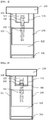
FIG. 1 to FIG. 5 are sectional views of an implant packaging container according to a first embodiment of the present invention. -
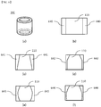
FIG. 6(a) is a perspective view of a main body and a main body reflector of the implant packaging container according to embodiments of the present invention, andFIG. 6(b) to FIG. 6(f) are sectional views of the main body of the implant packaging container shown inFIG. 6(a) . -
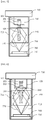
FIG. 7 to FIG. 11 are sectional views of an implant packaging container according to a second embodiment of the present invention. -
FIG. 12 to FIG. 13 are sectional views illustrating a coupled state of connection terminals of the implant packaging container according to the second embodiment of the present invention. - Embodiments of the present invention will be described in detail with reference to the accompanying drawings. Description of details apparent to those skilled in the art will be omitted.
-
FIG. 1 and FIG. 2 are sectional views of an implant packaging container according to a first embodiment of the present invention. - Referring to
FIG. 1 , the implant packaging container according to the first embodiment includes amain body 110 having aninner wall 111 defining a space for receiving a dental implant; acap 130 separably coupled to one side of themain body 110; a securingportion 120 securing a location of the dental implant inside themain body 110; abottom portion 150 coupled to themain body 110 to face thecap 130; and a main body reflector 380 disposed on an inner wall of themain body 110 and reflecting UV light emitted from near thebottom portion 150. - The
main body 110 is not limited to a particular shape and may have a polygonal barrel shape or a cylindrical shape. Preferably, themain body 110 has a cylindrical shape so as to allow the entirety of adental implant 100 received in the packaging container according to this embodiment to be irradiated with UV light reflected by thereflector 140. In addition, although themain body 110 may have any diameter and length so long as a typical dental implant can be received in the main body, themain body 110 may have a length of 10 mm to 30 mm and a diameter of 4 mm to 20 mm in consideration of reflection efficiency and economic feasibility. Themain body 110 may be formed of a transparent material to allow thedental implant 100 received therein to be observed from the outside. - The
cap 130 may be separably coupled to one side of themain body 110. Thesecuring portion 120 extending into themain body 110 may be mounted on thecap 130 and may be coupled to anabutment connector 102 of thedental implant 100. Here, inside the implant packaging container, thedental implant 100 may be secured by the securingportion 120 such that afixture 103 of thedental implant 100 faces thebottom portion 150 and amount 101 faces thecap 130. - Accordingly, in the implant packaging container, the
dental implant 100 is mounted on thesecuring portion 120 extending from thecap 130 and themain body 110 is coupled to thecap 130 to receive thedental implant 100 in the implant packaging container for storage or transfer of the dental implant. - Referring to
FIG. 2 , thesecuring portion 120 may include asecuring portion reflector 280 adapted to reflect UV light emitted into themain body 110 from thebottom portion 150. Since thefixture 103 of the dental implant includes threads and valleys repeatedly arranged in a spiral shape, a region of thefixture 103 may not be irradiated with UV light when UV light is emitted from thebottom portion 150 toward thecap 130 in only one direction. - As such, the implant packaging container further includes the securing
portion reflector 280, thereby allowing UV light to be emitted not only from thebottom portion 150 toward thecap 130 but also from thecap 130 toward thebottom portion 150. With this structure, the implant packaging container allows the entirety of the fixture of the dental implant to be uniformly irradiated with UV light before placement of the dental implant in the jawbone of a patient, thereby conveniently and efficiently improving hydrophilicity of the fixture to reduce patient pain through improvement in biological compatibility of the fixture with living tissue while reducing a time for bonding with the bone upon implantation. - The
bottom portion 150 may be coupled to the main body in an opposite direction to thecap 130, may be formed of a transparent material to allow UV light to pass therethrough, and may be detachably coupled to themain body 110. - As such, in some embodiments, the
bottom portion 150 may be detachably coupled to themain body 110 and a UV irradiator may be coupled to the main body at the opposite side of thecap 130 after detachment of thebottom portion 150 from themain body 110, thereby allowing the interior of themain body 110 to be irradiated with UV light emitted from the UV irradiator. - Alternatively, the
bottom portion 150 may be formed of a transparent material to allow UV light to pass therethrough and the UV irradiator may be disposed at the opposite side of thecap 130 without removing the bottom portion, thereby allowing the interior of themain body 110 to be irradiated with UV light emitted from the UV irradiator. - The implant packaging container may include the
main body reflector 140 on the inner wall of themain body 110 to emit UV light emitted from near thebottom portion 150. - The
main body reflector 140 may reflect UV light having passed through thebottom portion 150 and may include at least one selected from the group consisting of aluminum materials, a fluorine-based polymer, SUS, glass, ceramic materials, and combinations thereof. The fluorine-based polymer may include polytetrafluoroethylene (PTFE), polyvinyl fluoride (PVF), polyvinylidene fluoride (PVDF), polychlorotrifluoroethylene (PCTFE), fluorinated ethylene propylene (FEP), ethylene tetrafluoroethylene (ETFE), ethylene chlorotrifluoroethylene (ECTFE), perfluoropolyether (PFPE), and the like. Preferably, themain body reflector 140 is formed of aluminum or polytetrafluoroethylene. - The
main body reflector 140 may have a thickness of 300 nm to 5 cm. If the thickness of themain body reflector 140 is less than 300 nm, the main body reflector can have a significantly low reflectivity with respect to UV light, and if the thickness of themain body reflector 140 exceeds 5 cm, the volume of the implant packaging container increases too much, thereby reducing economic feasibility. - The
main body reflector 140 may have a length that is one third the length of thefixture 103 of the dental implant received in the main body. If the length of themain body reflector 140 is less than one third the length of thefixture 103, it is difficult for the entirety of thefixture 103 to be uniformly irradiated with UV light emitted into themain body 110. -
FIG. 6(a) is a perspective view of the main body and the main body reflector of the implant packaging container according to the first embodiment of the present invention, andFIG. 6(b) to FIG. 6(f) are sectional views of the main body of the implant packaging container shown inFIG. 6(a) . - Referring to
FIG. 1 andFIG. 6(a) to FIG. 6(f) , each ofmain body reflectors bottom portion 150 to thecap 130 to improve reflection efficiency such that the entirety of thefixture 103 of the dental implant can be irradiated with UV light emitted from thebottom portion 150 towards thecap 130 inside themain body 110. - Each of the
main body reflectors main body 110 formed of a reflective material. Specifically, themain body 110 or theinner wall 111 of the main body may be formed of a reflective material. In this case, it is possible to eliminate coating or deposition of a separate reflective material onto theinner wall 111 of the main body. - Alternatively, the
main body reflector 140 may be realized by a reflective material layer coated onto theinner wall 111 of the main body or an outer surface thereof. That is, when themain body 110 or theinner wall 111 of themain body 110 is formed of a UV light transmittable material, the reflective material layer may be coated on the outer surface of themain body 110. Coating of the reflective material layer may be performed by any method known in the art, for example, dipping, spraying, electro-deposition, blasting, spread coating, and the like. - In the structure wherein the
main body reflector 140 is provided to theinner wall 111 of the main body, themain body 110 is not necessarily formed of the UV light transmittable material and may be formed of a UV absorbable or reflective material. As such, in the implant packaging container according to the embodiment of the invention, themain body 110 is not necessarily formed of the UV light transmittable material, thereby enabling reduction in manufacturing costs. - Alternatively, the
main body reflector 140 may be realized by a reflective tape that can be bonded to the main body. Specifically, in the structure wherein themain body 110 or theinner wall 111 of themain body 110 is formed of the UV light transmittable material, the reflective tape may be bonded to the surface of themain body 110. - According to some embodiments, the
main body reflector 140 may be a barrel-shaped reflector inserted into themain body 110. - In these embodiments, referring to
FIG. 3, FIG. 4 ,FIG. 9 and FIG. 10 , the implant packaging container may further include at least onefastener 390; 490; 990; 1090 adapted to secure themain body reflector 140; 740 to theinner wall 111; 711 of the main body. - In addition, referring to
FIG. 5 andFIG. 11 , the implant packaging container may further include apedestal 590; 1190 disposed between themain body reflector 140; 740 and thebottom portion 150; 750 inside themain body 110; 710 to place the barrel-shapedmain body reflector 140; 740 thereon. -
FIG. 7 to FIG. 11 are sectional views of an implant packaging container according to a second embodiment of the present invention. - The implant packaging container according to the second embodiment is substantially identical to the implant packaging container according to the first embodiment in that the implant packaging container according to the second embodiment includes a
main body 710 including aninner wall 711 defining a space for receiving adental implant 100; acap 730 separably coupled to one side of themain body 710; a securingportion 720 securing a location of thedental implant 100 inside themain body 710; abottom portion 750 coupled to themain body 710 to face thecap 730; and amain body reflector 740 disposed on aninner wall 711 of themain body 710 and reflectingUV light 770 emitted into the main body. The implant packaging container according to the second embodiment may adopt the components of the implant packaging container described in the first embodiment. - In addition, the implant packaging container according to the second embodiment is substantially identical to the implant packaging container according to the first embodiment in that the thickness, length, shape and material of the
main body reflector 740 and a connection relationship between themain body 710 and themain body reflector 740 are the same as those of the implant packaging container according to the first embodiment, and further includes afastener 990; 1090 and apedestal 1190. The implant packaging container according to the second embodiment may adopt the components of the implant packaging container described in the first embodiment. - Thus, the following description will focus on a connection relationship between a
UV light source 760, thebottom portion 750, and a current supplier among the components of the implant packaging container according to the second embodiment. - The implant packaging container according to the second embodiment further includes the
UV light source 760 adapted to emit UV light into themain body 710. The UVlight source 760 may be mounted on thebottom portion 750. Thebottom portion 750 on which theUV light source 760 is mounted may be realized by a printed circuit board (PCB) or may include the PCB. -
FIG. 12 andFIG. 13 are sectional views illustrating a coupled state of connection terminals of the implant packaging container according to the second embodiment of the present invention. - Referring to
FIG. 12 , thebottom portion 750 may include afirst connection terminal 20 for connection to acurrent supplier 10. As shown inFIG. 12 , thefirst connection terminal 20 may be formed on a lower surface of thebottom portion 750. With this structure, when the implant packaging container is placed on thecurrent supplier 10, thefirst connection terminal 20 is connected to asecond connection terminal 30 of thecurrent supplier 10 to operate theUV light source 760. - Referring to
FIG. 13 , although thebottom portion 750 according to this embodiment is similar to thebottom portion 750 shown inFIG. 12 , thebottom portion 750 according to this embodiment extends outside themain body 710 and thefirst connection terminal 20 is formed on an upper surface of thebottom portion 750. Thefirst connection terminal 20 may be electrically connected to thecurrent supplier 10 through various connection structures. - Although the arrangement of the connection terminal is descried with reference to
FIG. 12 andFIG. 13 , it should be understood that the present invention is not limited to the connection terminals shown inFIG. 12 andFIG. 13 and may be modified into various shapes and thefirst connection terminal 20 may be connected to thecurrent supplier 10 having various shapes to allow thedental implant 100 received in the implant packaging container to be irradiated withUV light 770. - The UV
light source 760 may emit UV light having a wavelength of 200 nm to 380 nm, preferably 250 nm to 350 nm, to improve hydrophilicity of thefixture 103 and a sterilization effect. - In addition, although hydrophilicity of the
fixture 103 and the sterilization effect are improved with increasing light output of the UVlight source 760, it is desirable that an electric current of 0.01A to 2A and a voltage of 2V to 20V be used in consideration of light output generation efficiency. - When A indicates the shortest distance from the main body reflector to the dental implant and B indicates the shortest distance from the UV light source to the dental implant, A and B may be set to satisfy relationships of 0.1 mm ≤ A ≤ 50 mm and 0.7 ≤ B/A ≤ 1.
- If B/A is less than 0.7, the
fixture 103 can be damaged or suffer from deterioration in reflection efficiency due to contact between the UVlight source 760 and thefixture 103, and if B/A exceeds 1, hydrophilicity of thefixture 103 cannot be sufficiently secured due to an excessively long distance between a portion near theabutment connector 102 of thefixture 103 and the UVlight source 760. - Although some embodiments have been described herein, it should be understood that these embodiments are provided for illustration only and are not to be construed in any way as limiting the present invention. The scope of the present invention should be defined by the appended claims and equivalents thereof.
[List of Reference numerals] 110, 710, 1110: main body 111, 711: inner wall 120, 720: securing portion 130, 730: cap 150, 750: bottom portion 280, 880: securing portion reflector 760: UV light source 770: UV light 590, 1190: pedestal 390, 490, 990, 1090: fastener 100: dental implant 103: fixture 101: abutment 102: abutment connector 10: current supplier 20: first connection terminal 30: second connection terminal 140, 740, 640, 641, 642, 643, 644: main body reflector
Claims (18)
- A dental implant packaging container comprising:a main body having an inner wall defining a space for receiving a dental implant;a cap separably coupled to one side of the main body;a securing portion securing a location of the dental implant inside the main body;a bottom portion coupled to the main body to face the cap; anda main body reflector disposed on the inner wall of the main body and reflecting UV light emitted from near the bottom portion.
- The implant packaging container according to claim 1, further comprising:a dental implant mounted on the main body,wherein the dental implant comprises an abutment connector coupled to the securing portion, an abutment, and a fixture disposed between the securing portion and the bottom portion.
- The implant packaging container according to claim 1 or 2, wherein the bottom portion is detachable from the main body and UV light is emitted into the main body, with the bottom portion removed therefrom.
- The implant packaging container according to claim 1 or 2, wherein the securing portion comprises a securing portion reflector adapted to reflect UV light emitted into the main body from the bottom portion.
- The implant packaging container according to claim 1 or 2, wherein the main body reflector reflects UV light having passed through the bottom portion.
- The implant packaging container according to claim 1 or 2, wherein the main body reflector comprises at least one selected from the group consisting of aluminum materials, a fluorine-based polymer, SUS, glass, ceramic materials, and combinations thereof.
- The implant packaging container according to claim 6, wherein the main body reflector is formed of aluminum or polytetrafluoroethylene.
- The implant packaging container according to claim 1, wherein the main body reflector has a thickness of 0.003 mm to 50 mm.
- The implant packaging container according to claim 2, wherein a length of the main body reflector is one third the length of the fixture of the dental implant received in the main body.
- The implant packaging container according to claim 1, wherein the main body reflector comprises an inner wall region at least partially defining an inner space gradually narrowed from the bottom portion to the cap.
- The implant packaging container according to claim 1 or 2, wherein the main body reflector is realized by the main body formed of a reflective material.
- The implant packaging container according to claim 1 or 2, wherein the main body reflector is a reflective material layer coated on the inner wall of the main body.
- The implant packaging container according to claim 1 or 2, wherein the main body reflector is a reflective tape attached to the main body.
- The implant packaging container according to claim 1 or 2, wherein the main body reflector is a barrel-shaped reflector inserted into the main body.
- The implant packaging container according to claim 14, further comprising:at least one fastener securing the main body reflector to the inner wall of the main body.
- The implant packaging container according to claim 14, further comprising:a pedestal disposed between the main body reflector and the bottom portion inside the main body to place the main body reflector thereon.
- The implant packaging container according to claim 1 or 2, further comprising:a UV light source disposed on the bottom portion and emitting UV light into the main body.
- The implant packaging container according to claim 17, wherein, when A indicates the shortest distance from the main body reflector to the dental implant and B indicates the shortest distance from the UV light source to the dental implant, A and B are set to satisfy relationships of 0.1 mm ≤ A ≤ 50 mm and 0.7 ≤ B/A ≤ 1.
Applications Claiming Priority (2)
| Application Number | Priority Date | Filing Date | Title |
|---|---|---|---|
| KR1020160053953A KR102571404B1 (en) | 2016-05-02 | 2016-05-02 | An implant packing container |
| PCT/KR2017/004431 WO2017191925A1 (en) | 2016-05-02 | 2017-04-26 | Implant packaging container |
Publications (2)
| Publication Number | Publication Date |
|---|---|
| EP3449867A1 true EP3449867A1 (en) | 2019-03-06 |
| EP3449867A4 EP3449867A4 (en) | 2020-05-06 |
Family
ID=60202875
Family Applications (1)
| Application Number | Title | Priority Date | Filing Date |
|---|---|---|---|
| EP17792827.2A Pending EP3449867A4 (en) | 2016-05-02 | 2017-04-26 | IMPLANT PACKAGING CONTAINER |
Country Status (6)
| Country | Link |
|---|---|
| US (2) | US12178681B2 (en) |
| EP (1) | EP3449867A4 (en) |
| JP (1) | JP7002473B2 (en) |
| KR (1) | KR102571404B1 (en) |
| CN (3) | CN111067654A (en) |
| WO (1) | WO2017191925A1 (en) |
Cited By (1)
| Publication number | Priority date | Publication date | Assignee | Title |
|---|---|---|---|---|
| ES2790048A1 (en) * | 2019-04-25 | 2020-10-26 | Univ Del Pais Vasco / Euskal Herriko Unibertsitatea | SURFACE TREATMENT DEVICE FOR DENTAL IMPLANTS |
Families Citing this family (11)
| Publication number | Priority date | Publication date | Assignee | Title |
|---|---|---|---|---|
| KR102571404B1 (en) * | 2016-05-02 | 2023-08-29 | 서울바이오시스 주식회사 | An implant packing container |
| DE202017107752U1 (en) | 2017-12-20 | 2018-12-21 | Straumann Holding Ag | dental implant |
| KR102116867B1 (en) * | 2018-05-08 | 2020-05-29 | 주식회사 원익큐엔씨 | Surface treatment device for implant |
| US11864967B2 (en) * | 2018-08-28 | 2024-01-09 | Dio Corporation | Packaging container for dental implant |
| KR102076051B1 (en) | 2019-03-29 | 2020-02-12 | 주식회사 디오 | Apparatus for treating surface of medical metal |
| CN115297803B (en) * | 2020-03-04 | 2025-04-18 | 株式会社普拉斯 | Implant storage container |
| US11911232B2 (en) * | 2020-07-31 | 2024-02-27 | Dennis Manuel Köhrer | Container for storing a dental, especially endodontic instrument, kit and method |
| KR102304595B1 (en) * | 2020-11-26 | 2021-09-23 | 유진상 | Implant treatment Implant UV sterilization method |
| CN112875036A (en) * | 2021-03-10 | 2021-06-01 | 桂林市啄木鸟医疗器械有限公司 | Implant packaging bottle |
| JP2023029033A (en) * | 2021-08-20 | 2023-03-03 | 河村電器産業株式会社 | Apparatus storing box body |
| CN114343894A (en) * | 2022-02-17 | 2022-04-15 | 北京冠美口腔医院管理有限公司 | A dental implant osseointegration rate accelerator |
Family Cites Families (28)
| Publication number | Priority date | Publication date | Assignee | Title |
|---|---|---|---|---|
| DE29518880U1 (en) * | 1994-11-15 | 1996-02-01 | Gorbahn, Fritz, Dr.med., 58452 Witten | Sterilization system for sterilizing medical devices |
| US5755575A (en) * | 1996-08-16 | 1998-05-26 | Sulzer Calcitek, Inc. | Dental implant delivery system and method |
| EP0986341B1 (en) | 1997-06-02 | 2004-11-24 | Institut Straumann Ag | Retaining element for an implant and ampoule for preserving said implant |
| US7008226B2 (en) * | 2002-08-23 | 2006-03-07 | Woodwelding Ag | Implant, in particular a dental implant |
| US7490723B2 (en) * | 2004-06-23 | 2009-02-17 | Ricardo Levisman | Easy-to-open glass ampoule and device |
| DE102004049783B4 (en) * | 2004-10-12 | 2009-03-19 | Je Plasmaconsult Gmbh | Apparatus for processing goods with the aid of an electrical discharge |
| JP2006141821A (en) * | 2004-11-22 | 2006-06-08 | Ulvac Japan Ltd | Corrosion protection method |
| JP5004644B2 (en) * | 2007-04-23 | 2012-08-22 | 株式会社ジーシー | Fixture storage container |
| US8973747B2 (en) * | 2008-06-06 | 2015-03-10 | Thommen Medical Ag | Package for dental implant |
| CN201350228Y (en) * | 2009-02-05 | 2009-11-25 | 林美均 | Portable ultraviolet light sterilization cladding device |
| US20110049391A1 (en) * | 2009-09-01 | 2011-03-03 | Cheng-Pu Yang | Storage Container Having Sterilizing Function by Using Ultraviolet Rays |
| KR20110008520U (en) * | 2010-02-26 | 2011-09-01 | 오스템임플란트 주식회사 | Container for dental implant |
| WO2011113568A1 (en) * | 2010-03-15 | 2011-09-22 | Nobel Biocare Services Ag | Surface treatment method |
| KR101102993B1 (en) * | 2011-03-29 | 2012-01-05 | 주식회사 메가젠임플란트 | Surface treatment device for dental implants |
| WO2011152650A2 (en) * | 2010-05-31 | 2011-12-08 | 주식회사 메가젠임플란트 | Surface-processing device for a dental implant |
| JP5387537B2 (en) * | 2010-09-30 | 2014-01-15 | ウシオ電機株式会社 | Dental implant light irradiation device |
| JP5423634B2 (en) * | 2010-09-30 | 2014-02-19 | ウシオ電機株式会社 | Cleaning device for living body implants |
| JP5585473B2 (en) * | 2011-01-31 | 2014-09-10 | ウシオ電機株式会社 | UV irradiation device for implants |
| CN102538383B (en) * | 2012-03-01 | 2013-12-25 | 合肥美的电冰箱有限公司 | Sterilization and refreshing control method of refrigerator |
| KR101343817B1 (en) * | 2013-03-22 | 2013-12-20 | 주식회사 디오 | Dental implant fixture packing container |
| KR101445819B1 (en) * | 2013-05-14 | 2014-09-29 | 박규화 | UV irradiation system for the recovery of surface activity of aged dental implants |
| KR101483431B1 (en) * | 2014-01-14 | 2015-01-16 | 주식회사 디오 | Dental implant fixture packing case |
| CL2014001654A1 (en) * | 2014-06-20 | 2014-09-05 | Jose Portela Leon Francisco | An electrical delivery and packaging device for dental and orthopedic implants, of any size or composition because it is provided with an internal battery or electric power system that supplies electricity to LEDs or any lighting element, located at a minimum distance, around of the sides of the implant and arranged in 360 degrees around its surface. |
| WO2016198427A1 (en) * | 2015-06-12 | 2016-12-15 | Natural Dental Implants Ag | Systems and methods for sterile delivery of prostheses |
| KR101675508B1 (en) * | 2015-10-19 | 2016-11-11 | 주식회사 디오 | package for dental implant |
| JP3203603U (en) * | 2016-01-26 | 2016-04-07 | 株式会社ビィ・ソニック | UV irradiation equipment |
| KR101688931B1 (en) * | 2016-02-19 | 2017-01-02 | 주식회사 디오 | package for dental implant |
| KR102571404B1 (en) * | 2016-05-02 | 2023-08-29 | 서울바이오시스 주식회사 | An implant packing container |
-
2016
- 2016-05-02 KR KR1020160053953A patent/KR102571404B1/en active Active
-
2017
- 2017-04-26 US US16/098,334 patent/US12178681B2/en active Active
- 2017-04-26 WO PCT/KR2017/004431 patent/WO2017191925A1/en not_active Ceased
- 2017-04-26 EP EP17792827.2A patent/EP3449867A4/en active Pending
- 2017-04-26 CN CN201911345327.1A patent/CN111067654A/en active Pending
- 2017-04-26 CN CN201780027654.5A patent/CN109069235A/en active Pending
- 2017-04-26 JP JP2018557848A patent/JP7002473B2/en active Active
- 2017-05-02 CN CN201720478452.XU patent/CN207060875U/en not_active Expired - Fee Related
-
2024
- 2024-12-18 US US18/985,754 patent/US20250195180A1/en active Pending
Cited By (1)
| Publication number | Priority date | Publication date | Assignee | Title |
|---|---|---|---|---|
| ES2790048A1 (en) * | 2019-04-25 | 2020-10-26 | Univ Del Pais Vasco / Euskal Herriko Unibertsitatea | SURFACE TREATMENT DEVICE FOR DENTAL IMPLANTS |
Also Published As
| Publication number | Publication date |
|---|---|
| WO2017191925A1 (en) | 2017-11-09 |
| US20190159874A1 (en) | 2019-05-30 |
| US12178681B2 (en) | 2024-12-31 |
| EP3449867A4 (en) | 2020-05-06 |
| US20250195180A1 (en) | 2025-06-19 |
| CN109069235A (en) | 2018-12-21 |
| KR20170124265A (en) | 2017-11-10 |
| KR102571404B1 (en) | 2023-08-29 |
| JP2019514583A (en) | 2019-06-06 |
| CN207060875U (en) | 2018-03-02 |
| CN111067654A (en) | 2020-04-28 |
| JP7002473B2 (en) | 2022-01-20 |
Similar Documents
| Publication | Publication Date | Title |
|---|---|---|
| US20250195180A1 (en) | Implant packaging container | |
| EP3791825B1 (en) | Implant surface modification treatment device | |
| JP6726178B2 (en) | Adhesive device using UV element | |
| JP7232440B2 (en) | Fixing device | |
| US12588981B2 (en) | Surface treatment for an implant surface | |
| US20110300510A1 (en) | Dental implant | |
| TWI480026B (en) | Bio-implant having screw body selectively formed with nanoporous in spiral groove and method of making the same | |
| KR20210086912A (en) | Ultraviolet activator for implant | |
| CN113893051A (en) | Implant surface modification device | |
| KR101916171B1 (en) | Dental implant and abutment | |
| ES2614458T3 (en) | Method for the preparation of surfaces of devices made of titanium or alloys of titanium, zirconium, zirconia, alumina or zirconia / alumina compounds, stainless steels for medical use and cobalt-based superalloys for medical use implantable in the human or animal body, which They result in nanometric roughness, the formation of self-induced surface oxide, high anti-metalosis cleaning and possible preparation of parts with antimicrobial surface treatment | |
| CN109731135B (en) | Method for processing surface hydrophilicity of implant | |
| CN102232875B (en) | Biomedical implant structure with threaded structure and method for selective surface treatment thereof | |
| CN113893050A (en) | Implant surface modification device | |
| Duncan et al. | The effect of hydrothermal spark discharge anodization in the early integration of implants in sheep sinuses | |
| WO2015186388A1 (en) | Implant and method for producing same | |
| JP2007098054A (en) | Dental implant and abutment for dental implant | |
| KR20200021633A (en) | ultraviolet irradiation apparatus for surface treatment of dental implant | |
| KR102602281B1 (en) | Fixture storage container for implants for plasma surface treatment | |
| KR20180000142A (en) | Optical apparatus for promotion of sterilization and osseointegration of dental of implant | |
| KR20230104201A (en) | dental implant | |
| KR20200083194A (en) | Ultraviolet sterilizer for dental implant | |
| CN216455397U (en) | Implant surface modification device | |
| EP4697375A1 (en) | Plasma treatment vessel and plasma treatment device | |
| KR20150133671A (en) | Membrane for implant operation |
Legal Events
| Date | Code | Title | Description |
|---|---|---|---|
| STAA | Information on the status of an ep patent application or granted ep patent |
Free format text: STATUS: THE INTERNATIONAL PUBLICATION HAS BEEN MADE |
|
| PUAI | Public reference made under article 153(3) epc to a published international application that has entered the european phase |
Free format text: ORIGINAL CODE: 0009012 |
|
| STAA | Information on the status of an ep patent application or granted ep patent |
Free format text: STATUS: REQUEST FOR EXAMINATION WAS MADE |
|
| 17P | Request for examination filed |
Effective date: 20181130 |
|
| AK | Designated contracting states |
Kind code of ref document: A1 Designated state(s): AL AT BE BG CH CY CZ DE DK EE ES FI FR GB GR HR HU IE IS IT LI LT LU LV MC MK MT NL NO PL PT RO RS SE SI SK SM TR |
|
| AX | Request for extension of the european patent |
Extension state: BA ME |
|
| DAV | Request for validation of the european patent (deleted) | ||
| DAX | Request for extension of the european patent (deleted) | ||
| A4 | Supplementary search report drawn up and despatched |
Effective date: 20200402 |
|
| RIC1 | Information provided on ipc code assigned before grant |
Ipc: A61L 2/10 20060101ALI20200328BHEP Ipc: A61L 2/26 20060101ALI20200328BHEP Ipc: A61C 8/00 20060101AFI20200328BHEP Ipc: B65D 51/26 20060101ALI20200328BHEP Ipc: B65D 81/28 20060101ALI20200328BHEP |
|
| STAA | Information on the status of an ep patent application or granted ep patent |
Free format text: STATUS: EXAMINATION IS IN PROGRESS |
|
| 17Q | First examination report despatched |
Effective date: 20240429 |