EP3449866A1 - Orthodontic appliance and method for attaching orthodontic appliance - Google Patents
Orthodontic appliance and method for attaching orthodontic appliance Download PDFInfo
- Publication number
- EP3449866A1 EP3449866A1 EP17873346.5A EP17873346A EP3449866A1 EP 3449866 A1 EP3449866 A1 EP 3449866A1 EP 17873346 A EP17873346 A EP 17873346A EP 3449866 A1 EP3449866 A1 EP 3449866A1
- Authority
- EP
- European Patent Office
- Prior art keywords
- main body
- bracket main
- archwire
- opening
- closing lid
- Prior art date
- Legal status (The legal status is an assumption and is not a legal conclusion. Google has not performed a legal analysis and makes no representation as to the accuracy of the status listed.)
- Granted
Links
Images





Classifications
-
- A—HUMAN NECESSITIES
- A61—MEDICAL OR VETERINARY SCIENCE; HYGIENE
- A61C—DENTISTRY; APPARATUS OR METHODS FOR ORAL OR DENTAL HYGIENE
- A61C7/00—Orthodontics, i.e. obtaining or maintaining the desired position of teeth, e.g. by straightening, evening, regulating, separating, or by correcting malocclusions
- A61C7/12—Brackets; Arch wires; Combinations thereof; Accessories therefor
- A61C7/28—Securing arch wire to bracket
- A61C7/30—Securing arch wire to bracket by resilient means; Dispensers therefor
-
- A—HUMAN NECESSITIES
- A61—MEDICAL OR VETERINARY SCIENCE; HYGIENE
- A61C—DENTISTRY; APPARATUS OR METHODS FOR ORAL OR DENTAL HYGIENE
- A61C7/00—Orthodontics, i.e. obtaining or maintaining the desired position of teeth, e.g. by straightening, evening, regulating, separating, or by correcting malocclusions
- A61C7/12—Brackets; Arch wires; Combinations thereof; Accessories therefor
- A61C7/14—Brackets; Fixing brackets to teeth
- A61C7/145—Lingual brackets
-
- A—HUMAN NECESSITIES
- A61—MEDICAL OR VETERINARY SCIENCE; HYGIENE
- A61C—DENTISTRY; APPARATUS OR METHODS FOR ORAL OR DENTAL HYGIENE
- A61C7/00—Orthodontics, i.e. obtaining or maintaining the desired position of teeth, e.g. by straightening, evening, regulating, separating, or by correcting malocclusions
- A61C7/12—Brackets; Arch wires; Combinations thereof; Accessories therefor
- A61C7/14—Brackets; Fixing brackets to teeth
- A61C7/16—Brackets; Fixing brackets to teeth specially adapted to be cemented to teeth
-
- A—HUMAN NECESSITIES
- A61—MEDICAL OR VETERINARY SCIENCE; HYGIENE
- A61C—DENTISTRY; APPARATUS OR METHODS FOR ORAL OR DENTAL HYGIENE
- A61C7/00—Orthodontics, i.e. obtaining or maintaining the desired position of teeth, e.g. by straightening, evening, regulating, separating, or by correcting malocclusions
- A61C7/12—Brackets; Arch wires; Combinations thereof; Accessories therefor
- A61C7/28—Securing arch wire to bracket
- A61C7/285—Locking by rotation
-
- A—HUMAN NECESSITIES
- A61—MEDICAL OR VETERINARY SCIENCE; HYGIENE
- A61C—DENTISTRY; APPARATUS OR METHODS FOR ORAL OR DENTAL HYGIENE
- A61C7/00—Orthodontics, i.e. obtaining or maintaining the desired position of teeth, e.g. by straightening, evening, regulating, separating, or by correcting malocclusions
- A61C7/12—Brackets; Arch wires; Combinations thereof; Accessories therefor
- A61C7/28—Securing arch wire to bracket
- A61C7/287—Sliding locks
Definitions
- the present invention relates to dental braces and a method for attaching such dental braces. More specifically, the present invention relates to dental braces which are securely attached to teeth by simple processing such that sufficient adhesion strength can be maintained within the oral cavity of a person to be treated for a long time and to a method for attaching such dental braces.
- an orthodontic treatment for correcting the alignment of teeth a method is generally adopted in which orthodontic brackets are fitted to a tooth surface that is the surface of each tooth so as to apply, to each tooth, a mechanical tension force (the restoring force of pressing, pulling back, twisting, etc.) of an archwire attached to the orthodontic brackets of each adjacent tooth, and in which the positions of the teeth are gradually corrected into a proper teeth alignment condition.
- a mechanical tension force the restoring force of pressing, pulling back, twisting, etc.
- a groove is formed into which the orthodontic archwire can be inserted and whose cross section is substantially concave, the archwire is inserted into the groove and is thereafter fixed within the groove, the tension force applied to the archwire is made to act on the orthodontic bracket and thus the force for correction is made to act on the tooth via the orthodontic bracket (Patent Document 1).
- the orthodontic brackets as described above are normally fixed with an adhesive such as a resin to the teeth of a person to be treated and the model teeth of a set-up impression model taken from an impression of the person to be treated (hereinafter collectively referred to as "teeth")
- the orthodontic brackets are required to hold sufficient adhesion strength so that the orthodontic brackets are prevented from falling off the tooth surface during an orthodontic treatment.
- Patent Document 2 discloses that an undercut is formed in the tooth abutting surface of an orthodontic bracket. Specifically, a kneaded material containing a metal powder and a binding resin is injection molded, and an undercut is formed in the injection molded member obtained by the injection molding. As described above, the undercut is formed in the tooth abutting surface of the orthodontic bracket, and thus the surface area of an adhesion surface is increased such that the holding force of the adhesive is enhanced, with the result that adhesion strength can be enhanced.
- Patent Document 3 discloses an orthodontic bracket which is suitable for use of a photopolymerization adhesive when the orthodontic bracket is adhered to a tooth.
- the orthodontic bracket includes a base portion which has a mesh layer in a tooth abutting surface that is adhered to the tooth and a main body portion which is fixed to the upper surface of the base portion, and the orthodontic bracket has a structure where, in the upper surface of the base portion, a metallic layer to which the main body portion is fixed is provided and where the outer peripheral edge of the metallic layer is prevented from being protruded up to the mesh layer of the base portion.
- a light application unit which can apply light having a specific wavelength is used to apply visible light to the mesh layer containing the adhesive, and thus the adhesive is efficiently cured, with the result that the mesh layer of the base portion is securely fixed to the tooth.
- the photopolymerization adhesive is used, and thus in order to cure the adhesive contained in the mesh layer, for example, such expensive equipment as a light application unit, etc., is needed which can apply light having a specific wavelength, with the result that it is not always possible to easily practice the configuration thereof.
- the present invention is made in view of the foregoing, and an obj ect thereof is to provide dental braces in which sufficient adhesion strength can be maintained by simple processing within the oral cavity of a person to be treated for a long time and with which it is possible to reduce an uncomfortable feeling when the dental braces are fitted and a method for attaching such dental braces.
- a dental brace includes: a bracket main body portion in which an archwire insertion groove portion through which an archwire can be inserted and whose cross section is substantially concave is formed; an opening/closing lid portion which is coupled via a pivot to the bracket main body portion so as to be freely opened and closed with respect to the archwire insertion groove portion; and a tooth abutting plate portion which includes, on one surface side, a first surface portion that abuts on the surface of a tooth on the side of a tongue, and on a side opposite to the first surface portion, a second surface portion that includes an adhering surface portion to which the bracket main body portion is adhered and in which a charge hole portion where the diameter of an inner wall surface on the side of the second surface portion is wider than the diameter of the inner wall surface on the side of the first surface portion is formed.
- the dental brace includes the bracket main body portion in which the archwire insertion groove portion whose cross section is substantially concave is formed, and thus it is possible to insert the archwire through the archwire insertion groove portion by a simple operation.
- the dental brace includes the opening/closing lidportion which is coupled via the pivot to the bracket main body portion so as to be freely opened and closed with respect to the archwire insertion groove portion, and thus the opening/closing lid portion is changed from an opened state to a closed state in a state where the archwire is installed within the archwire insertion groove portion, with the result that it is possible to prevent the archwire from falling out of the inside of the archwire insertion groove portion.
- the dental brace includes the tooth abutting plate portion which includes, on one surface side, the first surface portion that abuts on the surface of the tooth on the side of the tongue, and on the side opposite to the first surface portion, the second surface portion that includes the adhering surface portion to which the bracket main body portion is adhered, and thus it is possible to attach the dental brace to the teeth in a state where the bracket main body portion is adhered to the adhering surface portion as the second surface portion in an integrated manner.
- the charge hole portion is formed in which the diameter of the inner wall surface on the side of the second surface portion is wider than the diameter of the inner wall surface on the side of the first surface portion, and thus when a tooth abutting surface is made to abut on, for example, the model teeth of a set-up impression model so as to be attached, part of an adhesive applied to the tooth abutting surface enters the charge hole portion so as to be charged, and thereafter the adhesive is cured within the charge hole portion.
- the adhesive cured within the charge hole portion functions as a member for preventing the tooth abutting plate portion from being removed in the direction outside of the dental brace, and thus the adhesion strength of the dental brace on the teeth can be maintained for a long time.
- the adhesive which is charged into the charge hole portion and is cured functions, by the step portion, as the member for preventing the tooth abutting plate portion from being removed in the direction outside of the dental brace, and thus the adhesion strength of the dental brace on the teeth can be maintained for a long time.
- the adhesive which is charged into the charge hole portion and is cured functions, by the step portion, as the member for preventing the tooth abutting plate portion from being removed in the direction outside of the dental brace, and thus the adhesion strength of the dental brace on the teeth can be maintained for a long time.
- bracket main body portion In a case where, in the bracket main body portion, a fitting concave portion whose cross section is substantially concave is formed, and where, in the opening/closing lidportion, aprotrusion portion is provided which can be fitted to the fitting concave portion when the opening/closing lid portion is changed from an opened state to a closed state for the archwire insertion groove portion, the bracket main body portion and the opening/closing lid portion can be securely tightened.
- the bracket main body portion and the opening/closing lid portion can be securely tightened.
- the dental brace includes a string-shaped member with which the bracket main body portion and the opening/closing lid portion are securely tightened without interference with the archwire inserted through the archwire insertion groove portion, the bracket main body portion and the opening/closing lid portion canbe securely tightened.
- the opening/closing lid portion is opened with respect to the bracket main body portion, and thus it is possible to prevent the archwire from falling out of the inside of the archwire insertion groove portion.
- the bracket main body portion In a case where the archwire insertion groove portion of the bracket main body portion is formed so as to be curved along the surface of the tooth on the side of the tongue in the direction of alignment of the teeth with a predetermined radius of curvature, for example, when the dental brace is installed on the incisor and the canine tooth arranged along the direction of alignment of the teeth with the predetermined radius of curvature, the bracket main body portion easily slides with respect to the archwire, and thus it is possible to prevent a locking phenomenon. Hence, it is possible to easily locate the dental brace on the teeth.
- the dental brace When the radius of curvature of the archwire insertion groove portion is set within a range of R15 to R20, the dental brace can be placed along the average curved surface of the teeth in the person to be treated, and thus the dental brace can be made to more smoothly slide with respect to the archwire.
- the dental brace can be placed along the average curved surface of the central incisor and the canine tooth in the person to be treated, and thus the dental brace can be made to most smoothly slide with respect to the archwire.
- the dental brace can be placed along the average curved surface of the central incisor and the canine tooth, and thus the dental brace can be made to most smoothly slide with respect to the archwire.
- the bracket main body portion In a case where the archwire insertion groove portion of the bracket main body portion is formed linearly along the surface of the tooth on the side of the tongue in the direction of alignment of teeth, for example, when the dental braces are installed on the premolars arranged linearly along the direction of alignment of the teeth, the bracket main body portion easily slides with respect to the archwire, and thus it is possible to prevent a locking phenomenon. Hence, it is possible to easily locate the dental brace on the teeth.
- a method for attaching a dental brace includes: a step of applying an adhesive to a first surface portion of a tooth abutting plate portion in which an opening/closing lid portion is provided that is coupled to a bracket main body portion so as to be freely opened and closed with respect to an archwire insertion groove portion which is formed in the bracket main body portion and through which an archwire is inserted and in which a charge hole portion is formed where the diameter of an inner wall surface on the side of a second surface portion including an adhering surface portion to which the bracket main body portion is adhered is wider than the diameter of the inner wall surface on the side of the first surface portion that is a side opposite to the second surface portion; a step of making the side of the first surface portion abut on the surface of a set-up impression model on the side of a tongue; a step of making the adhesive enter the charge hole portion; a step of curing the adhesive; a step of inserting the archwire through the archwire insertion groove portion
- the step of making the dental brace abut on the surface of the model teeth of the set-up impression model on the side of the tongue is included, and thus the side of the first surface portion to which the adhesive is applied is made to abut on the surface of the model teeth on the side of the tongue, with the result that the dental brace can be fixed to the set-up impression model.
- the step of making the adhesive enter the charge hole portion is included, and thus the adhesive applied to the side of the first surface portion is made to enter the inside of the charge hole portion so as to be pressed thereinto when the dental brace is made to abut on the model teeth, with the result that a sufficient amount of adhesive can be charged into the charge hole portion.
- the step of inserting the archwire through the archwire insertion groove portion formed in the bracket main body portion is included, and thus the archwire is installed into the dental brace, with the result that a certain tension can be made to act on the teeth.
- the step of securely tightening the bracket main body portion and the opening/closing lid portion without the bracket main body portion and the opening/closing lid portion interfering with the archwire is included, and thus the bracket main body portion and the opening/closing lidportioncanbe securely tightened.
- the opening/closing lid portion is opened with respect to the bracket main body portion, with the result that it is possible to prevent the archwire from falling out of the inside of the archwire insertion groove portion.
- the dental brace can be attached by a simple operation of engaging the string-shaped member with the bracket main body portion and the opening/closing lid portion.
- the dental brace can be attached by a simple operation of passing the string-shaped member through the through hole portion and then engaging the string-shaped member with the first engagement groove portion formed in the bracket main body portion, and since part of the string-shaped member is passed through the through hole portion, even when a larger rotation torque from the archwire acts on the dental brace, the state where the bracket main body portion and the opening/closing lid portion are securely tightened can be maintained.
- the dental brace is securely attached to teeth by simple processing, and within the oral cavity of a person to be treated, sufficient adhesion strength can be maintained for a long time.
- Embodiments of the present invention on dental braces and a method for attaching such dental braces will be described below with reference to drawings so as to understand the present invention.
- the description will be given based on a state where dental braces 1 are fitted to teeth T on the side of a lower jaw, and the direction of an upper jaw is defined as being upward and the direction of the lower jaw is defined as being downward.
- Fig. 1 is an overall view showing a state where the dental braces 1 according to the present invention are attached to a set-up impression model M on the side of the lower jaw which is produced based on an impression taken from a person to be treated.
- the dental braces 1 whose raw material is stainless steel, titanium, ceramic, etc., and whose shapes differ according to the types of teeth T (mainly a central incisor T1, a lateral incisor T2, a canine tooth T3, a first premolar T4 and a second premolar T5) abut on the surface of the teeth T on the side of a tongue.
- the dental braces 1 do not always need to be formed of a raw material such as stainless steel, titanium or ceramic. Any material may be used as long as the material is prevented from being degraded, corroded or damaged even in a harsh use environment within an oral cavity and is confirmed to be safe in medical terms.
- a dental brace 1a according to a first embodiment of the present invention will first be described with reference to Figs. 2 to 6 .
- the dental braces 1a can also be attached to the other teeth T (for example, the first premolar T4 and the second premolar T5).
- the dental braces 1a are shaped along the surface of the central incisor T1, the lateral incisor T2 and the canine tooth T3 on the side of the tongue, and the dental brace 1a has a vertically long shape as a whole and is mainly formed with a bracket main body portion 2a, an opening/closing lid portion 3a and a tooth abutting plate portion 4a.
- anarchwire insertion groove portion 21 is formed whose cross section is substantially concave and which is opened obliquely upward when the dental braces 1a are fitted to the teeth T (which is opened obliquely downward when the dental braces 1a are fitted to the teeth T on the side of the upper jaw).
- An archwire W is inserted into the archwire insertion groove portion 21, and thus it is possible to correct the alignment of the teeth of the person to be treated with a biasing force corresponding to the initial shape.
- the archwire insertion groove portion 21 does not always need to be opened obliquely upward (obliquely downward) in a state where the bracket main body portion 2a is attached to the person to be treated, and the archwire insertion groove portion 21 may be opened in any direction.
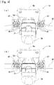
- Fig. 4 is an enlarged view of a main portion when the archwire insertion groove portion 21 is seen in plan view along the direction of alignment of the teeth in a state where the archwire W is attached to the inside of the archwire insertion groove portion 21.
- the archwire insertion groove portion 21 is formed in the shape of a smooth arc along the direction of alignment of the central incisor T1, the lateral incisor T2 and the canine tooth T3 with a predetermined radius of curvature (R15 to R20).
- the central incisor T1 the lateral incisor T2 and the canine tooth T3 are aligned as a whole with the predetermined radius of curvature
- a curved portion is formed in the positions of the archwire W corresponding to the central incisor T1, the lateral incisor T2 and the canine tooth T3.
- the archwire insertion groove portion 21 is formed along the curved portion of the archwire W with the predetermined radius of curvature so as to have the shape of a smooth arc.
- the archwire insertion groove portion 21 is formed such that the radius of curvature of the archwire insertion groove portion 21 formed in the dental brace 1a installed on the side of the upper jaw is R20 and that the radius of curvature of the archwire insertion groove portion 21 formed in the dental brace 1a installed on the side of the lower jaw is R15.
- the archwire insertion groove portion 21 may be formed linearly along the direction of alignment of the teeth.
- the archwire insertion groove portion 21 is formed along the direction of alignment of the central incisor T1, the lateral incisor T2 and the canine tooth T3 in the shape of an arc, and thus the dental braces 1a individually installed in the central incisor T1, the lateral incisor T2 and the canine tooth T3 can slide with respect to the archwire W such that the locking phenomenon of the dental braces 1a is prevented from occurring when they are fitted to the person to be treated, with the result that it is possible to easily locate the dental braces 1a with respect to the person to be treated.
- the archwire insertion groove portion 21 is preferably formed in the shape of an arc.
- the radius of curvature of the archwire insertion groove portion 21 is not always necessary to set within the range of R15 to R20.
- the radius of curvature can be changed as necessary according to the state of alignment of the teeth in the person to be treated.
- the radius of curvature of the curved portion of the archwire W formed in the central incisor T1, the lateral incisor T2 and the canine tooth T3 falls within the range of R15 to R20, and in particular, the radius of curvature of the archwire insertion groove portions 21 formed in the dental braces 1a installed in the central incisor T1, lateral incisor T2 and the canine tooth T3 on the side of the upper jaw is set to R20 and the radius of curvature of the archwire insertion groove portions 21 formed in the dental braces 1a installed in the central incisor T1, lateral incisor T2 and the canine tooth T3 on the side of the lower jaw is set
- a pair of main body side pivot portions 24 where main body side pivot hole portions 23 through which a pivot pin 22 to be described later can be inserted are formed are provided so as to protrude to the side of the tongue .
- a first engagement groove portion 25 with which part of a string-shaped member 5 to be described later can engage and whose cross section is substantially concave is formed along the direction of alignment of the teeth in the bracket main body portion 2a so as to be opened upward.
- a lid side pivot portion 32 is provided whose outer surface is formed in the shape of a gentle curved surface and in which a lid side pivot hole portion 31 overlaid on the main body side pivot hole portions 23 of the bracket main body portion 2a is formed.
- the opening/closing lid portion 3a is brought into an opened state for the archwire insertion groove portion 21, the archwire W is attached to the archwire insertion groove portion 21 and thereafter as shown in Fig. 3(b) , the opening/closing lid portion 3a is brought into a closed state for the archwire insertion groove portion 21, with the result that the archwire W can be prevented from falling out of the archwire insertion groove portion 21.
- the outer surface of the opening/closing lid portion 3a does not always need to be formed in the shape of a curved surface.
- the outer surface of the opening/closing lid portion 3a is formed in the shape of a curved surface, for example, when the dental braces 1a are installed within the oral cavity of the person to be treated, even if the tongue of the person to be treated is brought into contact with the opening/closing lid portion 3a, the person to be treated is prevented from feeling pain.
- the outer surface of the opening/closing lid portion 3a is preferably formed in the shape of a curved surface.
- opening/closing lid portion 3a It is not always necessary to attach the opening/closing lid portion 3a to the bracket main body portion 2a via the pivot pin 22. As long as the opening/closing lid portion 3a is attached to the archwire insertion groove portion 21 formed in the bracket main body portion 2a so as to be freely opened and closed, a method for attaching it can be selected from known means as necessary.
- a second engagement groove portion 33 is formed with which the string-shaped member 5 to be described later can engage and whose cross section is substantially concave, and substantially around the center of the opening/closing lid portion 3a, a through hole portion 34 is formed which penetrates the opening/closing lidportion 3a in a short-length direction.
- the tooth abutting plate portion 4a is processed to be curved, as shown in Fig. 2 , along the shape of the surface of the central incisor T1, the lateral incisor T2 and the canine tooth T3 on which the tooth abutting plate portion 4a abuts on the side of the tongue, includes, on one surface side, a first surface portion 41 which abuts on the surface of the central incisor T1, the lateral incisor T2 and the canine tooth T3 on the side of the tongue and includes, in a region of a substantially center of the other surface side (the side of the bracket main body portion) on a side opposite to the first surface portion 41, a second surface portion 42 which includes an adhering surface portion 43 to which the integrally molded bracket main body portion 3a is adhered.
- the tooth abutting plate portion 4a it is not always necessary for the tooth abutting plate portion 4a to be curved along the shape of the surface of the central incisor T1, the lateral incisor T2 and the canine tooth T3 on which the tooth abutting plate portion 4a abuts on the side of the tongue, and the tooth abutting plate portion 4a may be formed linearly.
- the tooth abutting plate portion 4a is processed to be curved, and thus the adherence of the tooth abutting plate portion 4a to the central incisor T1, the lateral incisor T2 and the canine tooth T3 is enhanced, with the result that sufficient adhesion strength can be maintained within the oral cavity of the person to be treated for a long time.
- bracket main body portion 3a and the tooth abutting plate portion 4a may be integrally mold. It is not always necessary to integrally mold the bracket main body portion 3a and the tooth abutting plate portion 4a.
- the bracket main body portion 3a and the tooth abutting plate portion 4a may be molded as separate members.
- a total of eleven charge hole portions 44 are formed, that is, four charge hole portions 44 are formed in each of the positions symmetrical with respect to the adhering surface portion 43 to which the bracket main body portion 2a is adhered in the direction of alignment of the teeth, two charge hole portions 44 are formed in an upper position and one charge hole portion 44 is formed in a lower position. Furthermore, around the charge hole portions 44 on the side of the first surface portion 41 of the tooth abutting plate portion 4a, a plurality of convex thread portions 45 are provided so as to extend from the first surface portion 41 toward the side of the teeth T.
- the charge hole portions 44 may be formed in any region as long as the region is the peripheral edge of the adhering surface portion 43.
- the charge hole portions 44 are formed symmetrically with respect to at least the adhering surface portion 43 in the direction of alignment of the teeth, and thus an effect as an anti-removal member caused by an adhesive R can be made to uniformly act on the entire dental brace 1, with the result that adhesion strength can be further enhanced.
- the charge hole portion 44 includes, in its cross-sectional shape, a step portion 46 in a predetermined position of an inner wall surface on the side of the second surface portion 42, and a diameter on the side of the second surface portion 42 is made wider than a diameter on the side of the first surface portion 41. Furthermore, on the side of the second surface portion 42, a V-shaped groove portion 47 whose cross section is substantially V-shaped is formed so as to pass through a substantially center of a pair of charge hole portions 44.
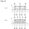
- the diameter of the charge hole portion 44 on the side of the second surface portion 42 is made wider than the diameter on the side of the first surface portion 41, and thus as shown in Fig. 5(a) , the adhesive R which is cured within the charge hole portion 44 functions as the member for preventing the tooth abutting plate portion 4a from being removed in an outward direction. Hence, sufficient adhesion strength can be maintained within the oral cavity of the person to be treated for a long time.
- the step portion 46 in the inner wall surface of the charge hole portion 44 on the side of the second surface portion 42.
- the diameter on the side of the second surface portion 42 is made wider than the diameter on the side of the first surface portion 41, the step portion 46 may be formed in any position of the inner wall surface of the charge hole portion 44.
- convex thread portions 45 are provided on the first surface portion 41 of the tooth abutting plate portion 4a.
- a plurality of convex thread portions 45 are provided along the direction of alignment of the charge hole portions 44, and thus it is possible to increase the contact area of the adhesive R which is applied to the first surface portion 41, with the result that the convex thread portions 45 are preferably provided in terms of enhancing adhesion strength.
- V-shaped groove portion 47 It is not always necessary to form the V-shaped groove portion 47 on the side of the second surface portion 42. However, the V-shaped groove portion 47 is formed, and thus it is possible to increase, in the second surface portion 42, the contact area of the adhesive R which enters from the charge hole portion 44, with the result that the V-shaped groove portion 47 is preferably formed in terms of enhancing adhesion strength.
- the adhesive R is first applied to the first surface portion 41 of the tooth abutting plate portion 4a.
- part of the adhesive R applied to the first surface portion 41 enters the charge hole portions 44 as shown in Fig. 5(b) and is thereafter cured.
- the diameter on the side of the first surface portion 41 in the charge hole portion 44 is made wider than the diameter on the side of the second surface portion 42, and thus the cured adhesive R functions as the member for preventing the tooth abutting plate portion 4a from being removed in the direction of the side of the tongue.
- the string-shaped member 5 is a string-shaped member which regulates the movement of the opening/closing lid portion 3a to an opened position in a state where the opening/closing lid portion 3a is brought into a closed position for the archwire insertion groove portion 21 without interference with the archwire W, and is formed with, for example, an elastic resin member (hereinafter referred to as an "elastic string-shaped member 51") or a stainless steel member (hereinafter referred to as a "stainless steel string-shaped member 52").
- an elastic string-shaped member 51 an elastic resin member
- a stainless steel member 52 hereinafter referred to as a "stainless steel string-shaped member 52"
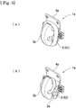
- the elastic string-shaped member 51 is engaged with the first engagement groove portion 25 formed in the bracket main body portion 2a and the second engagement groove portion 33 formed in the opening/closing lid portion 3a so as to be securely tightened, and thus the bracket main body portion 2a and the opening/closing lid portion 3a are integrated.
- the treatment progresses, and at a later stage of treatment, as shown in Fig. 6(b) , the stainless steel string-shaped member 52 is engaged with the first engagement groove portion 25 formed in the bracket main body portion 2a and the through hole portion 34 formed in the opening/closing lid portion 3a so as to be securely tightened, and thus the bracket main body portion 2a and the opening/closing lid portion 3a are integrated.
- the elastic string-shaped member 51 As the string-shaped member 5 at an early stage of treatment, and for example, the stainless steel string-shaped member 52 may be used.
- the archwire W whose diameter is small is used, a rotation torque which acts from the archwire W on the dental braces 1a is relatively small.
- the elastic string-shaped member 51 since at an early stage of treatment, the elastic string-shaped member 51 is used, there is no possibility that the rotation torque produced by the archwire W damages the elastic string-shaped member 51, with the result that, at an early stage of treatment, a relatively inexpensive elastic string-shaped member 51 is preferably used.
- the stainless steel string-shaped member 52 As the string-shaped member 5 at a later stage of treatment, and for example, the elastic string-shaped member 51 may be used.
- the archwire W whose diameter is larger than the diameter at an early stage is used, a rotation torque which acts from the archwire W on the dental braces 1a is relatively large .
- the elastic string-shaped member 51 is used instead of the stainless steel string-shaped member 52, there is a possibility that the elastic string-shaped member 51 is damaged by the rotation torque produced by the archwire W.
- a dental brace 1b according to a second embodiment of the present invention will then be described with reference to Figs. 7 to 9 .
- the dental braces 1b can be attached to the other teeth T (for example, the central incisor T1, the lateral incisor T2 and the canine tooth T3).
- the same portions as in the other embodiments are identified with the same signs, and repeated description will be omitted.
- the dental brace 1b according to the second embodiment is also mainly formed with a bracket main body portion 2b, an opening/closing lid portion 3b and a tooth abutting plate portion 4b.
- an archwire insertion groove portion 21 whose cross section is substantially concave and which is opened upward is formed.
- the shape of the surface of the first premolar T4 and the second premolar T5 on the side of the tongue is basically linear along the direction of alignment of the teeth, and thus the archwire insertion groove portion 21 is linearly formed along the direction of alignment of the teeth, with the result that the dental brace 1b can slide with respect to the archwire W.
- the archwire insertion groove portion 21 does not always need to be opened upward in a state where the bracket main body portion 2c is attached to the tooth T, and the bracket main body portion may be opened in any direction.
- bracket main body portion 2b fitting concave portions 26 to which protrusion portions 35 provided on the lid side pivot portion 32 of the opening/closing lid portion 3b to be described later can be fitted are formed so as to be opened to the side of the tongue, and a pair of main body side pivot portions 24 are provided where main body side pivot hole portions 23 which are adjacent to the fitting concave portions 26 and through which a pivot pin 22 can be inserted are formed.
- an opening/closing shaft is attached via the pivot pin 22 to the lid side pivot portion 32 whose outer surface is formed in the shape of a substantially hemispherical surface and in which a lid side pivot hole portion 31 overlaid on the main body side pivot hole portions 23 of the bracket main body portion 2b is formed so as to be freely opened and closed.
- the lid side pivot portion 32 of the opening/closing lid portion 3b the protrusion portions 35 to which the fitting concave portions 26 formed in the bracket main body portion 2b can be fitted and which are protruded laterally are provided.
- the opening/closing lid portion 3b is brought into an opened state
- the archwire W is attached to the archwire insertion groove portion 21 and thereafter as shown in Fig. 8(b)
- the opening/closing lid portion 3b is brought into a closed state, with the result that the archwire W can be prevented from falling out of the archwire insertion groove portion 21.
- the protrusion portions 35 of the opening/closing lid portion 3b are fitted to the fitting concave portions 26 of the bracket main body portion 2b, and thus the bracket main body portion 3b and the opening/closing lid portion 4b can be integrated.
- the opening/closing lid portion 3b does not always need to be attached via the pivot pin 22 to the bracket main body portion 2b.
- a method for attaching it can be selected from known means as necessary.
- the opening/closing lid portion 3b does not need to be formed in the shape of a substantially hemispherical surface, and any shape may be adopted as long as the opening/closing lid portion 3b is formed in the shape of a smooth curve.
- the bracket main body portion 2b and the opening/closing lidportion 3b do not need to be integrated by fitting of the protrusion portions 35 provided on the opening/closing lid portion 3b to the fitting concave portions 26 formed in the bracket main body portion 2.
- they may be integrated with the elastic string-shaped member 51 described previously.
- the tooth abutting plate portion 4b includes, on one surface side, a smooth first surface portion 41 that abuts on the surface of the first premolar T4 and the second premolar T5 on the side of the tongue and includes, in a region of a substantially center of the other surface side, a second surface portion 42 that includes an adhering surface portion 43 to which the bracket main body portion 2b is adhered.
- the tooth abutting plate portion 4b is processed to be curved along the shape of the surface of the first premolar T4 and the second premolar T5 on the side of the tongue.
- charge hole portions 44 are formed in each of the positions symmetrical with respect to the adhering surface portion 43 of the tooth abutting plate portion 4b in the direction of alignment of the teeth. As shown in Fig. 9(a) , the charge hole portion 44 is formed in a substantially tapered shape which extends from the side of the second surface portion 42 of the tooth abutting plate portion 4b to the side of the first surface portion 41.
- the charge hole portions 44 may be formed in any region as long as the region is the peripheral edge of the adhering surface portion 43. However, the charge hole portions 44 are formed in the positions symmetrical with respect to the adhering surface portion 43 in the direction of alignment of the teeth, and thus an effect as an anti-removal member caused by an adhesive R can be made to uniformly act on the entire dental brace 1b, with the result that adhesion strength can be further enhanced.
- the first surface portion 41 of the tooth abutting plate portion 4b does not need to be smooth.
- the convex thread portions 45 may be provided.
- the charge hole portion 44 does not always need to be formed in a substantially tapered shape which extends from the side of the second surface portion 42 to the side of the first surface portion 41.
- a configuration may be adopted in which, as described in the first embodiment, a step portion is formed in the inner wall surface of the charge hole portion 44 such that a diameter on the side of the first surface portion 41 of the charge hole portion 44 is made wider than a diameter on the side of the second surface portion 42.
- the adhesive R is first applied to the first surface portion 41 of the tooth abutting plate portion 4b.
- part of the adhesive R applied to the first surface portion 41 enters the charge hole portions 44 as shown in Fig. 9(b) and is thereafter cured.
- the charge hole portion 44 is formed in a tapered shape which extends from the second surface portion 42 to the first surface portion 41, and thus the cured adhesive R functions as a member for preventing the tooth abutting plate portion 4b from being removed in the direction of the side of the tongue.
- a dental brace 1c according to a third embodiment of the present invention will then be described with reference to Fig. 10 .
- the dental braces 1c can be attached to the other teeth T (for example, the central incisor T1, the lateral incisor T2 and the canine tooth T3).
- the same portions as in the other embodiments are identified with the same signs, and repeated description will be omitted.
- the dental brace 1c according to the third embodiment differs from the second embodiment in the shape of an opening/closing lid portion 3c as shown in Fig. 10(a) .
- a through hole portion 34 is formed in the opening/closing lid portion 3c.
- the through hole portion 34 has the same function as the through hole portion 34 of the dental brace 1a according to the first embodiment.
- protrusion portions 35 provided on the lid side pivot hole portion 31 of the opening/closing lid portion 3c are fitted to fitting concave portions 26 formed in a bracket main body portion 2c, and thus the bracket main body portion 2c and the opening/closing lid portion 3c are integrated.
- a stainless steel string-shaped member 52 is engaged with a first engagement groove portion 25 formed in the bracket main body portion 2c and the through hole portion 34 formed in the opening/closing lid portion 3c so as to be securely tightened, and thus the bracket main body portion 2c and the opening/closing lid portion 3c are integrated.
- the archwire W which is used As the archwire W which is used, the archwire W whose diameter is larger than the diameter at an early stage of treatment is used, and thus a rotation torque which is larger than that at an early stage of treatment acts from the archwire W on the dental braces 1c.
- the integration of the bracket main body portion 2c and the opening/closing lid portion 3c cannot be kept only by fitting of the protrusion portions 35 and the fitting concave portions 26.
- the stainless steel string-shapedmember 52 is engaged with the first engagement groove portion 25 and the through hole portion 34 so as to be securely tightened, and thus even when a large torque acts from the archwire W on the dental brace 1c, the integration of the bracket main body portion 2c and the opening/closing lid portion 3c can be kept.
- the stainless steel string-shaped member 52 as the string-shaped member 5, and for example, the elastic string-shapedmember 51 maybe used.
- the stainless steel string-shaped member 52 which can secure a certain degree of rigidity.
- a dental brace 1d according to a reference embodiment of the present invention will then be described with reference to Fig. 11 .
- the dental braces 1d can be attached to the other teeth T (for example, the first premolar T4 and the second premolar T5).
- the same portions as in the other embodiments are identified with the same signs, and repeated description will be omitted.
- the dental braces 1d are shaped along the surface of the central incisor T1, the lateral incisor T2 and the canine tooth T3 on the side of the tongue, and the dental brace 1d has a vertically long shape as a whole and is mainly formed with a bracket main body portion 2d, an opening/closing lid portion 3d and a tooth abutting plate portion 4d.
- an archwire insertion groove portion 21 is formed in the shape of an arc with a predetermined radius of curvature (R15 to R20) along the direction of alignment of the teeth, and thus the dental brace 1d can slide with respect to the archwire W.
- the dental brace 1d which is installed on the canine tooth T3 is formed in the shape of an arc with the predetermined radius of curvature (R15 to R20) or is formed linearly according to the state of the alignment of the teeth in the person to be treated.
- the outer surface thereof is formed in the shape of a gentle curved surface, and a second engagement groove portion 33 withwhich a string- shaped member 5 to be described later is engaged and whose cross section is substantially concave is formed.
- the tooth abutting plate portion 4d includes, on one surface side, a smooth first surface portion 41 that abuts on the surface of the central incisor T1, the lateral incisor T2 and the canine tooth T3 on the side of the tongue and includes, in a region of a substantially center of the other surface side (the side of the bracket main body portion 2d) on a side opposite to the first surface portion 41, a second surface portion 42 that includes an adhering surface portion 43 to which the bracket main body portion 3b is adhered.
- the string-shaped member 5 is a string-shaped member which regulates the movement of the opening/closing lid portion 3d to an opened position in a state where the opening/closing lid portion 3d is brought into a closed position for the archwire insertion groove portion 21 without interference with the archwire W, and can be formed with an elastic string-shaped member 51 or a stainless steel member 52. As shown in Fig. 11 (b) , the string-shaped member 5 is engaged with the first engagement groove portion 25 and the second engagement groove portion 33 so as to be securely tightened, and thus the bracket main body portion 2d and the opening/closing lid portion 3d are integrated.
- the dental braces are securely attached to the teeth, and thus sufficient adhesion strength can be maintained within the oral cavity of the person to be treated for a long time.
Landscapes
- Health & Medical Sciences (AREA)
- Oral & Maxillofacial Surgery (AREA)
- Dentistry (AREA)
- Epidemiology (AREA)
- Life Sciences & Earth Sciences (AREA)
- Animal Behavior & Ethology (AREA)
- General Health & Medical Sciences (AREA)
- Public Health (AREA)
- Veterinary Medicine (AREA)
- Dental Tools And Instruments Or Auxiliary Dental Instruments (AREA)
Abstract
Description
- The present invention relates to dental braces and a method for attaching such dental braces. More specifically, the present invention relates to dental braces which are securely attached to teeth by simple processing such that sufficient adhesion strength can be maintained within the oral cavity of a person to be treated for a long time and to a method for attaching such dental braces.
- Conventionally, as an orthodontic treatment for correcting the alignment of teeth, a method is generally adopted in which orthodontic brackets are fitted to a tooth surface that is the surface of each tooth so as to apply, to each tooth, a mechanical tension force (the restoring force of pressing, pulling back, twisting, etc.) of an archwire attached to the orthodontic brackets of each adjacent tooth, and in which the positions of the teeth are gradually corrected into a proper teeth alignment condition.
- Specifically, in the orthodontic bracket, a groove is formed into which the orthodontic archwire can be inserted and whose cross section is substantially concave, the archwire is inserted into the groove and is thereafter fixed within the groove, the tension force applied to the archwire is made to act on the orthodontic bracket and thus the force for correction is made to act on the tooth via the orthodontic bracket (Patent Document 1).
- Incidentally, although the orthodontic brackets as described above are normally fixed with an adhesive such as a resin to the teeth of a person to be treated and the model teeth of a set-up impression model taken from an impression of the person to be treated (hereinafter collectively referred to as "teeth"), the orthodontic brackets are required to hold sufficient adhesion strength so that the orthodontic brackets are prevented from falling off the tooth surface during an orthodontic treatment.
- For example, Patent Document 2 discloses that an undercut is formed in the tooth abutting surface of an orthodontic bracket. Specifically, a kneaded material containing a metal powder and a binding resin is injection molded, and an undercut is formed in the injection molded member obtained by the injection molding. As described above, the undercut is formed in the tooth abutting surface of the orthodontic bracket, and thus the surface area of an adhesion surface is increased such that the holding force of the adhesive is enhanced, with the result that adhesion strength can be enhanced.
- In addition, Patent Document 3 discloses an orthodontic bracket which is suitable for use of a photopolymerization adhesive when the orthodontic bracket is adhered to a tooth. Specifically, the orthodontic bracket includes a base portion which has a mesh layer in a tooth abutting surface that is adhered to the tooth and a main body portion which is fixed to the upper surface of the base portion, and the orthodontic bracket has a structure where, in the upper surface of the base portion, a metallic layer to which the main body portion is fixed is provided and where the outer peripheral edge of the metallic layer is prevented from being protruded up to the mesh layer of the base portion.
- Then, a light application unit which can apply light having a specific wavelength is used to apply visible light to the mesh layer containing the adhesive, and thus the adhesive is efficiently cured, with the result that the mesh layer of the base portion is securely fixed to the tooth.
-
- Patent Document 1: Japanese Patent No.
5624094 - Patent Document 2: Japanese Unexamined Patent Application Publication No.
2000-96103 - Patent Document 3: Japanese Unexamined Patent Application Publication No.
2014-144200 - Incidentally, since in general, the size of a dental brace is relatively small, an advanced and precise operation is required for processing and formation of the dental brace. In this regard, when an undercut is formed as disclosed in Patent Document 2, since the operation process thereof is significantly complicated, the number of steps in manufacturing and the product cost are disadvantageously increased.
- In the dental brace disclosed in Patent Document 3, although adhesion force to the teeth is enhanced by the mesh layer as an adhesive holding layer, since the mesh layer is formed as a member separate from the dental brace, a step of attaching the mesh layer to the dental brace by diffusion joining or welding, etc., is needed, with the result that as in Patent Document 2, the number of steps in manufacturing and the product cost are disadvantageously increased.
- Furthermore, in Patent Document 3, as the adhesive, the photopolymerization adhesive is used, and thus in order to cure the adhesive contained in the mesh layer, for example, such expensive equipment as a light application unit, etc., is needed which can apply light having a specific wavelength, with the result that it is not always possible to easily practice the configuration thereof.
- The present invention is made in view of the foregoing, and an obj ect thereof is to provide dental braces in which sufficient adhesion strength can be maintained by simple processing within the oral cavity of a person to be treated for a long time and with which it is possible to reduce an uncomfortable feeling when the dental braces are fitted and a method for attaching such dental braces.
- In order to achieve the object described above, a dental brace according to the present invention includes: a bracket main body portion in which an archwire insertion groove portion through which an archwire can be inserted and whose cross section is substantially concave is formed; an opening/closing lid portion which is coupled via a pivot to the bracket main body portion so as to be freely opened and closed with respect to the archwire insertion groove portion; and a tooth abutting plate portion which includes, on one surface side, a first surface portion that abuts on the surface of a tooth on the side of a tongue, and on a side opposite to the first surface portion, a second surface portion that includes an adhering surface portion to which the bracket main body portion is adhered and in which a charge hole portion where the diameter of an inner wall surface on the side of the second surface portion is wider than the diameter of the inner wall surface on the side of the first surface portion is formed.
- Here, the dental brace includes the bracket main body portion in which the archwire insertion groove portion whose cross section is substantially concave is formed, and thus it is possible to insert the archwire through the archwire insertion groove portion by a simple operation.
- The dental brace includes the opening/closing lidportion which is coupled via the pivot to the bracket main body portion so as to be freely opened and closed with respect to the archwire insertion groove portion, and thus the opening/closing lid portion is changed from an opened state to a closed state in a state where the archwire is installed within the archwire insertion groove portion, with the result that it is possible to prevent the archwire from falling out of the inside of the archwire insertion groove portion.
- The dental brace includes the tooth abutting plate portion which includes, on one surface side, the first surface portion that abuts on the surface of the tooth on the side of the tongue, and on the side opposite to the first surface portion, the second surface portion that includes the adhering surface portion to which the bracket main body portion is adhered, and thus it is possible to attach the dental brace to the teeth in a state where the bracket main body portion is adhered to the adhering surface portion as the second surface portion in an integrated manner.
- In the tooth abutting plate portion, the charge hole portion is formed in which the diameter of the inner wall surface on the side of the second surface portion is wider than the diameter of the inner wall surface on the side of the first surface portion, and thus when a tooth abutting surface is made to abut on, for example, the model teeth of a set-up impression model so as to be attached, part of an adhesive applied to the tooth abutting surface enters the charge hole portion so as to be charged, and thereafter the adhesive is cured within the charge hole portion. Here, the adhesive cured within the charge hole portion functions as a member for preventing the tooth abutting plate portion from being removed in the direction outside of the dental brace, and thus the adhesion strength of the dental brace on the teeth can be maintained for a long time.
- When, in the charge hole portion, a step portion is provided in a predetermined position of the inner wall surface, the adhesive which is charged into the charge hole portion and is cured functions, by the step portion, as the member for preventing the tooth abutting plate portion from being removed in the direction outside of the dental brace, and thus the adhesion strength of the dental brace on the teeth can be maintained for a long time.
- When, in the charge hole portion, the inner wall surface is formed in a substantially tapered shape which extends from the side of the second surface portion to the side of the first surface portion, the adhesive which is charged into the charge hole portion and is cured functions, by the step portion, as the member for preventing the tooth abutting plate portion from being removed in the direction outside of the dental brace, and thus the adhesion strength of the dental brace on the teeth can be maintained for a long time.
- When a plurality of charge hole portions are formed in a peripheral edge of the adhering surface portion, the effect as the anti-removal member caused by the adhesive charged into the charge hole portion acts on the entire dental brace, and thus the adhesion strength of the dental brace on the teeth can be maintained for a long time.
- When, in a peripheral edge of the charge hole portion in the first surface portion, a plurality of convex thread portions are provided, since it is possible to increase the adherence area of the adhesive when the adhesive is applied to the first surface portion, the adhesion strength of the dental brace on the teeth can be enhanced.
- In a case where, in the bracket main body portion, a fitting concave portion whose cross section is substantially concave is formed, and where, in the opening/closing lidportion, aprotrusion portion is provided which can be fitted to the fitting concave portion when the opening/closing lid portion is changed from an opened state to a closed state for the archwire insertion groove portion, the bracket main body portion and the opening/closing lid portion can be securely tightened. Hence, for example, even when a rotation torque produced by the archwire acts on the dental brace, there is no possibility that the opening/closing lid portion is opened with respect to the bracket main body portion, and thus it is possible to prevent the archwire from falling out of the inside of the archwire insertion groove portion.
- When the dental brace includes a string-shaped member with which the bracket main body portion and the opening/closing lid portion are securely tightened without interference with the archwire inserted through the archwire insertion groove portion, the bracket main body portion and the opening/closing lid portion canbe securely tightened. Hence, for example, even when the rotation torque produced by the archwire acts on the dental brace, there is no possibility that the opening/closing lid portion is opened with respect to the bracket main body portion, and thus it is possible to prevent the archwire from falling out of the inside of the archwire insertion groove portion.
- In a case where the string-shaped member is engaged with a first engagement groove portion which is formed in the bracket main body portion and whose cross section is substantially concave and a second engagement groove portion which is formed in the opening/closing lid portion and whose cross section is substantially concave, when the bracket main body portion and the opening/closing lid portion are securely tightened with the string-shaped member, it is possible to attach the dental brace by a simple operation of engaging the string-shaped member with the bracket main body portion and the opening/closing lid portion.
- In a case where the string-shaped member is engaged with the first engagement groove portion which is formed in the bracket main body portion and whose cross section is substantially concave and a through hole portion which is formed in the opening/closing lid portion, when the bracket main body portion and the opening/closing lid portion are securely tightened with the string-shaped member, it is possible to attach the dental brace by a simple operation of passing the string-shaped member through the through hole portion and then engaging the string-shaped member with the first engagement groove portion formed in the bracket main body portion, and since part of the string-shaped member is passed through the through hole portion, even when a larger rotation torque from the archwire acts on the dental brace, the state where the bracket main body portion and the opening/closing lid portion are securely tightened can be maintained.
- In a case where the archwire insertion groove portion of the bracket main body portion is formed so as to be curved along the surface of the tooth on the side of the tongue in the direction of alignment of the teeth with a predetermined radius of curvature, for example, when the dental brace is installed on the incisor and the canine tooth arranged along the direction of alignment of the teeth with the predetermined radius of curvature, the bracket main body portion easily slides with respect to the archwire, and thus it is possible to prevent a locking phenomenon. Hence, it is possible to easily locate the dental brace on the teeth.
- When the radius of curvature of the archwire insertion groove portion is set within a range of R15 to R20, the dental brace can be placed along the average curved surface of the teeth in the person to be treated, and thus the dental brace can be made to more smoothly slide with respect to the archwire.
- When the radius of curvature of the archwire insertion groove portion in the bracket main body portion installed on an upper jaw is R20, for example, the dental brace can be placed along the average curved surface of the central incisor and the canine tooth in the person to be treated, and thus the dental brace can be made to most smoothly slide with respect to the archwire.
- When the radius of curvature of the archwire insertion groove portion in the bracket main body portion installed on a lower jaw is R15, for example, the dental brace can be placed along the average curved surface of the central incisor and the canine tooth, and thus the dental brace can be made to most smoothly slide with respect to the archwire.
- In a case where the archwire insertion groove portion of the bracket main body portion is formed linearly along the surface of the tooth on the side of the tongue in the direction of alignment of teeth, for example, when the dental braces are installed on the premolars arranged linearly along the direction of alignment of the teeth, the bracket main body portion easily slides with respect to the archwire, and thus it is possible to prevent a locking phenomenon. Hence, it is possible to easily locate the dental brace on the teeth.
- In order to achieve the object described above, a method for attaching a dental brace according to the present invention includes: a step of applying an adhesive to a first surface portion of a tooth abutting plate portion in which an opening/closing lid portion is provided that is coupled to a bracket main body portion so as to be freely opened and closed with respect to an archwire insertion groove portion which is formed in the bracket main body portion and through which an archwire is inserted and in which a charge hole portion is formed where the diameter of an inner wall surface on the side of a second surface portion including an adhering surface portion to which the bracket main body portion is adhered is wider than the diameter of the inner wall surface on the side of the first surface portion that is a side opposite to the second surface portion; a step of making the side of the first surface portion abut on the surface of a set-up impression model on the side of a tongue; a step of making the adhesive enter the charge hole portion; a step of curing the adhesive; a step of inserting the archwire through the archwire insertion groove portion; and a step of securely tightening the bracket main body portion and the opening/closing lidportion without the bracket main body portion and the opening/closing lid portion interfering with the archwire.
- Here, the step of applying the adhesive to the first surface portion of the tooth abutting plate portion in which the opening/closing lidportion is provided that is coupled to the bracket main body portion so as to be freely opened and closed with respect to the archwire insertion groove portion which is formed in the bracket main body portion and through which the archwire is inserted and in which the charge hole portion is formed where the diameter of the inner wall surface on the side of the second surface portion including the adhering surface portion to which the bracket main body portion is adhered is wider than the diameter of the inner wall surface on the side of the first surface portion that is the side opposite to the second surface portion is included, and thus part of the adhesive applied to the first surface portion is made to efficiently enter the charge hole portion, with the result that the adhesive can be charged into the charge hole portion.
- The step of making the dental brace abut on the surface of the model teeth of the set-up impression model on the side of the tongue is included, and thus the side of the first surface portion to which the adhesive is applied is made to abut on the surface of the model teeth on the side of the tongue, with the result that the dental brace can be fixed to the set-up impression model.
- The step of making the adhesive enter the charge hole portion is included, and thus the adhesive applied to the side of the first surface portion is made to enter the inside of the charge hole portion so as to be pressed thereinto when the dental brace is made to abut on the model teeth, with the result that a sufficient amount of adhesive can be charged into the charge hole portion.
- The step of inserting the archwire through the archwire insertion groove portion formed in the bracket main body portion is included, and thus the archwire is installed into the dental brace, with the result that a certain tension can be made to act on the teeth.
- The step of securely tightening the bracket main body portion and the opening/closing lid portion without the bracket main body portion and the opening/closing lid portion interfering with the archwire is included, and thus the bracket main body portion and the opening/closing lidportioncanbe securely tightened. Hence, for example, even when a rotation torque from the archwire acts on the dental brace, there is no possibility that the opening/closing lid portion is opened with respect to the bracket main body portion, with the result that it is possible to prevent the archwire from falling out of the inside of the archwire insertion groove portion.
- In a case where, in the step of securely tightening the bracket main body portion and the opening/closing lid portion without the bracket main body portion and the opening/closing lid portion interfering with the archwire, a string-shaped member is engaged with a first engagement groove portion which is formed in the bracket main body portion and whose cross section is substantially concave and a second engagement groove portion which is formed in the opening/closing lid portion and whose cross section is substantially concave, when the bracket main body portion and the opening/closing lid portion are securely tightened with the string-shaped member, the dental brace can be attached by a simple operation of engaging the string-shaped member with the bracket main body portion and the opening/closing lid portion.
- In a case where, in the step of securely tightening the bracket main body portion and the opening/closing lid portion without the bracket main body portion and the opening/closing lid portion interfering with the archwire, the string-shaped member is engaged with the first engagement groove portion which is formed in the bracket main body portion and whose cross section is substantially concave and a through hole portion which is formed in the opening/closing lid portion, when the bracket main body portion and the opening/closing lid portion are securely tightened with the string-shaped member, the dental brace can be attached by a simple operation of passing the string-shaped member through the through hole portion and then engaging the string-shaped member with the first engagement groove portion formed in the bracket main body portion, and since part of the string-shaped member is passed through the through hole portion, even when a larger rotation torque from the archwire acts on the dental brace, the state where the bracket main body portion and the opening/closing lid portion are securely tightened can be maintained.
- In a dental brace and a method for attaching such a dental brace according to the present invention, the dental brace is securely attached to teeth by simple processing, and within the oral cavity of a person to be treated, sufficient adhesion strength can be maintained for a long time.
-
-
Fig. 1 is a diagram showing a state where dental braces are attached to teeth; -
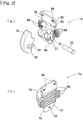
Fig. 2 is a perspective view of a dental brace according to a first embodiment of the present invention,Fig. 2(a) is a diagram of a front side (the side of a tongue) in an exploded state andFig. 2(b) is a diagram of a back side (the side of the teeth) in an assembled state; -
Fig. 3 is a side view of the dental brace according to the first embodiment of the present invention,Fig. 3(a) is a diagram showing a state where an opening/closing lid portion is opened andFig. 3(b) is a diagram showing a state where the opening/closing lid portion is closed; -
Fig. 4 is an enlarged view of a main portion of an archwire insertion groove portion in the dental brace according to the first embodiment of the present invention,Fig. 4 (a) is a diagram showing the archwire insertion groove portion which has a predetermined curvature andFig. 4(b) is a diagram showing a linear archwire insertion groove portion; -
Fig. 5 is an enlarged cross-sectional view showing charge hole portions in the dental brace according to the first embodiment of the present invention,Fig. 5 (a) is a diagram showing a state before an adhesive is charged andFig. 5(b) is a diagram showing a state after the adhesive is charged; -
Fig. 6 is a perspective view in which a string-shaped member in the dental brace according to the first embodiment of the present invention is attached,Fig. 6(a) is a diagram showing a state of an early stage of treatment andFig. 6(b) is a diagram showing a state of a later stage of treatment; -
Fig. 7 is a perspective view of a dental brace according to a second embodiment of the present invention,Fig. 7 (a) is a diagram showing an exploded state andFig. 7(b) is a diagram showing an assembled state; -
Fig. 8 is a side view of the dental brace according to the second embodiment of the present invention,Fig. 8(a) is a diagram showing a state where an opening/closing lid portion is opened andFig. 8(b) is a diagram showing a state where the opening/closing lid portion is closed; -
Fig. 9 is an enlarged cross-sectional view showing charging holes in the dental brace according to the second embodiment of the present invention,Fig. 9 (a) is a diagram showing a state before an adhesive is charged andFig. 9(b) is a diagram showing a state after the adhesive is charged; -
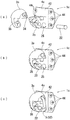
Fig. 10 is a perspective view of a dental brace according to a third embodiment of the present invention,Fig. 10 (a) is a diagram showing an exploded state,Fig. 10(b) is a diagram showing a state of an early stage of treatment andFig. 10(c) is a diagram showing a state of a later of stage treatment; and -
Fig. 11 is a perspective view of a dental brace in a reference embodiment of the present invention,Fig. 11(a) is a diagram showing an exploded state andFig. 11(b) is a diagram showing an assembled state. - Embodiments of the present invention on dental braces and a method for attaching such dental braces will be described below with reference to drawings so as to understand the present invention. For convenience of description of individual drawings, the description will be given based on a state where dental braces 1 are fitted to teeth T on the side of a lower jaw, and the direction of an upper jaw is defined as being upward and the direction of the lower jaw is defined as being downward.
-
Fig. 1 is an overall view showing a state where the dental braces 1 according to the present invention are attached to a set-up impression model M on the side of the lower jaw which is produced based on an impression taken from a person to be treated. The dental braces 1 whose raw material is stainless steel, titanium, ceramic, etc., and whose shapes differ according to the types of teeth T (mainly a central incisor T1, a lateral incisor T2, a canine tooth T3, a first premolar T4 and a second premolar T5) abut on the surface of the teeth T on the side of a tongue. - Here, the dental braces 1 do not always need to be formed of a raw material such as stainless steel, titanium or ceramic. Any material may be used as long as the material is prevented from being degraded, corroded or damaged even in a harsh use environment within an oral cavity and is confirmed to be safe in medical terms.
- A
dental brace 1a according to a first embodiment of the present invention will first be described with reference toFigs. 2 to 6 . Although, for convenience of description, the embodiment in which thedental braces 1a are attached to the central incisor T1, the lateral incisor T2 and the canine tooth T3 will be described, thedental braces 1a can also be attached to the other teeth T (for example, the first premolar T4 and the second premolar T5). - The
dental braces 1a are shaped along the surface of the central incisor T1, the lateral incisor T2 and the canine tooth T3 on the side of the tongue, and thedental brace 1a has a vertically long shape as a whole and is mainly formed with a bracketmain body portion 2a, an opening/closing lid portion 3a and a tooth abuttingplate portion 4a. - In the bracket
main body portion 2a, anarchwireinsertion groove portion 21 is formed whose cross section is substantially concave and which is opened obliquely upward when thedental braces 1a are fitted to the teeth T (which is opened obliquely downward when thedental braces 1a are fitted to the teeth T on the side of the upper jaw). An archwire W is inserted into the archwireinsertion groove portion 21, and thus it is possible to correct the alignment of the teeth of the person to be treated with a biasing force corresponding to the initial shape. - Here, the archwire
insertion groove portion 21 does not always need to be opened obliquely upward (obliquely downward) in a state where the bracketmain body portion 2a is attached to the person to be treated, and the archwireinsertion groove portion 21 may be opened in any direction. - The shape of the archwire
insertion groove portion 21 will be described with reference toFig. 4. Fig. 4 is an enlarged view of a main portion when the archwireinsertion groove portion 21 is seen in plan view along the direction of alignment of the teeth in a state where the archwire W is attached to the inside of the archwireinsertion groove portion 21. As shown inFig. 4(a) , the archwireinsertion groove portion 21 is formed in the shape of a smooth arc along the direction of alignment of the central incisor T1, the lateral incisor T2 and the canine tooth T3 with a predetermined radius of curvature (R15 to R20). - Specifically, since the central incisor T1, the lateral incisor T2 and the canine tooth T3 are aligned as a whole with the predetermined radius of curvature, when the archwire W is formed along the alignment of the teeth of the person to be treated, a curved portion is formed in the positions of the archwire W corresponding to the central incisor T1, the lateral incisor T2 and the canine tooth T3. Hence, the archwire
insertion groove portion 21 is formed along the curved portion of the archwire W with the predetermined radius of curvature so as to have the shape of a smooth arc. - Since in general, the curvature of alignment of the teeth on the side of the upper jaw is gentler than the curvature of alignment of the teeth on the side of the lower jaw, in the embodiment of the present invention, the archwire
insertion groove portion 21 is formed such that the radius of curvature of the archwireinsertion groove portion 21 formed in thedental brace 1a installed on the side of the upper jaw is R20 and that the radius of curvature of the archwireinsertion groove portion 21 formed in thedental brace 1a installed on the side of the lower jaw is R15. - Here, it is not always necessary to form the archwire
insertion groove portion 21 with the predetermined radius of curvature in the shape of an arc. For example, the archwireinsertion groove portion 21 may be formed linearly along the direction of alignment of the teeth. However, the archwireinsertion groove portion 21 is formed along the direction of alignment of the central incisor T1, the lateral incisor T2 and the canine tooth T3 in the shape of an arc, and thus thedental braces 1a individually installed in the central incisor T1, the lateral incisor T2 and the canine tooth T3 can slide with respect to the archwire W such that the locking phenomenon of thedental braces 1a is prevented from occurring when they are fitted to the person to be treated, with the result that it is possible to easily locate thedental braces 1a with respect to the person to be treated. Hence, the archwireinsertion groove portion 21 is preferably formed in the shape of an arc. - It is not always necessary to set the radius of curvature of the archwire
insertion groove portion 21 within the range of R15 to R20. For example, the radius of curvature can be changed as necessary according to the state of alignment of the teeth in the person to be treated. However, as a result of examinations repeated by the inventors, in general, the radius of curvature of the curved portion of the archwire W formed in the central incisor T1, the lateral incisor T2 and the canine tooth T3 falls within the range of R15 to R20, and in particular, the radius of curvature of the archwireinsertion groove portions 21 formed in thedental braces 1a installed in the central incisor T1, lateral incisor T2 and the canine tooth T3 on the side of the upper jaw is set to R20 and the radius of curvature of the archwireinsertion groove portions 21 formed in thedental braces 1a installed in the central incisor T1, lateral incisor T2 and the canine tooth T3 on the side of the lower jaw is set to R15, with the result that it is possible to make thedental braces 1a slide with respect to the archwire W most smoothly. - In the canine tooth T3, depending on the person to be treated, when the archwire W is formed along the alignment of the teeth, it is likely that the curved portion is not formed in the position corresponding to the tooth T3 so as to be formed linearly. Hence, as shown in
Fig. 4(b) , it may be preferable to form the archwireinsertion groove portion 21 of the dental brace 1 linearly instead of the shape of an arc, however, the shape of the archwireinsertion groove portion 21 can be changed as necessary according to the alignment of the teeth in the person to be treated. - On the lower side of the archwire
insertion groove portion 21, a pair of main bodyside pivot portions 24 where main body sidepivot hole portions 23 through which apivot pin 22 to be described later can be inserted are formed are provided so as to protrude to the side of the tongue . On the upper side of the archwireinsertion groove portion 21, a firstengagement groove portion 25 with which part of a string-shapedmember 5 to be described later can engage and whose cross section is substantially concave is formed along the direction of alignment of the teeth in the bracketmain body portion 2a so as to be opened upward. - In the opening/
closing lid portion 3a, a lidside pivot portion 32 is provided whose outer surface is formed in the shape of a gentle curved surface and in which a lid sidepivot hole portion 31 overlaid on the main body sidepivot hole portions 23 of the bracketmain body portion 2a is formed. When the opening/closing lid portion 3a is attached to the bracketmain body portion 2a, the lid sidepivot hole portion 31 of the opening/closing lid portion 3a is overlaid on the main body sidepivot hole portions 23 of the bracketmain body portion 2a, thepivot pin 22 is inserted such that they are fixed and thus the opening/closing lid portion 3a is attached to the archwireinsertion groove portion 21 so as to be freely opened and closed. - Specifically, when the archwire W is attached to the archwire
insertion groove portion 21 of the bracketmain body portion 2a, as shown inFig. 3(a) , the opening/closing lid portion 3a is brought into an opened state for the archwireinsertion groove portion 21, the archwire W is attached to the archwireinsertion groove portion 21 and thereafter as shown inFig. 3(b) , the opening/closing lid portion 3a is brought into a closed state for the archwireinsertion groove portion 21, with the result that the archwire W can be prevented from falling out of the archwireinsertion groove portion 21. - Here, the outer surface of the opening/
closing lid portion 3a does not always need to be formed in the shape of a curved surface. However, in a case where the outer surface of the opening/closing lid portion 3a is formed in the shape of a curved surface, for example, when thedental braces 1a are installed within the oral cavity of the person to be treated, even if the tongue of the person to be treated is brought into contact with the opening/closing lid portion 3a, the person to be treated is prevented from feeling pain. Hence, the outer surface of the opening/closing lid portion 3a is preferably formed in the shape of a curved surface. - It is not always necessary to attach the opening/
closing lid portion 3a to the bracketmain body portion 2a via thepivot pin 22. As long as the opening/closing lid portion 3a is attached to the archwireinsertion groove portion 21 formed in the bracketmain body portion 2a so as to be freely opened and closed, a method for attaching it can be selected from known means as necessary. - In the vicinity of the lid side
pivot hole portion 31 on the side of one end of the opening/closing lid portion 3a, a secondengagement groove portion 33 is formed with which the string-shapedmember 5 to be described later can engage and whose cross section is substantially concave, and substantially around the center of the opening/closing lid portion 3a, a throughhole portion 34 is formed which penetrates the opening/closing lidportion 3a in a short-length direction. - The tooth abutting
plate portion 4a is processed to be curved, as shown inFig. 2 , along the shape of the surface of the central incisor T1, the lateral incisor T2 and the canine tooth T3 on which the tooth abuttingplate portion 4a abuts on the side of the tongue, includes, on one surface side, afirst surface portion 41 which abuts on the surface of the central incisor T1, the lateral incisor T2 and the canine tooth T3 on the side of the tongue and includes, in a region of a substantially center of the other surface side (the side of the bracket main body portion) on a side opposite to thefirst surface portion 41, asecond surface portion 42 which includes an adheringsurface portion 43 to which the integrally molded bracketmain body portion 3a is adhered. - Here, it is not always necessary for the tooth abutting
plate portion 4a to be curved along the shape of the surface of the central incisor T1, the lateral incisor T2 and the canine tooth T3 on which the tooth abuttingplate portion 4a abuts on the side of the tongue, and the tooth abuttingplate portion 4a may be formed linearly. However, the tooth abuttingplate portion 4a is processed to be curved, and thus the adherence of the tooth abuttingplate portion 4a to the central incisor T1, the lateral incisor T2 and the canine tooth T3 is enhanced, with the result that sufficient adhesion strength can be maintained within the oral cavity of the person to be treated for a long time. - It is not always necessary to integrally mold the bracket
main body portion 3a and the tooth abuttingplate portion 4a. The bracketmain body portion 3a and the tooth abuttingplate portion 4a may be molded as separate members. - In the tooth abutting
plate portion 4a, a total of elevencharge hole portions 44 are formed, that is, fourcharge hole portions 44 are formed in each of the positions symmetrical with respect to the adheringsurface portion 43 to which the bracketmain body portion 2a is adhered in the direction of alignment of the teeth, twocharge hole portions 44 are formed in an upper position and onecharge hole portion 44 is formed in a lower position. Furthermore, around thecharge hole portions 44 on the side of thefirst surface portion 41 of the tooth abuttingplate portion 4a, a plurality ofconvex thread portions 45 are provided so as to extend from thefirst surface portion 41 toward the side of the teeth T. - Here, it is not always necessary to form the total of eleven
charge hole portions 44. The number ofcharge hole portions 44 can be changed as necessary according to the area of the tooth abuttingplate portion 4a, etc. - It is not always necessary to form the
charge hole portions 44 in the positions symmetrical with respect to the adheringsurface portion 43 in the direction of alignment of the teeth, thecharge hole portions 44 in the upper position and thecharge hole portion 44 in the lower position. Thecharge hole portions 44 may be formed in any region as long as the region is the peripheral edge of the adheringsurface portion 43. However, thecharge hole portions 44 are formed symmetrically with respect to at least the adheringsurface portion 43 in the direction of alignment of the teeth, and thus an effect as an anti-removal member caused by an adhesive R can be made to uniformly act on the entire dental brace 1, with the result that adhesion strength can be further enhanced. - As showninFig. 5(a), the
charge hole portion 44 includes, in its cross-sectional shape, astep portion 46 in a predetermined position of an inner wall surface on the side of thesecond surface portion 42, and a diameter on the side of thesecond surface portion 42 is made wider than a diameter on the side of thefirst surface portion 41. Furthermore, on the side of thesecond surface portion 42, a V-shapedgroove portion 47 whose cross section is substantially V-shaped is formed so as to pass through a substantially center of a pair ofcharge hole portions 44. - In other words, as described above, the diameter of the
charge hole portion 44 on the side of thesecond surface portion 42 is made wider than the diameter on the side of thefirst surface portion 41, and thus as shown inFig. 5(a) , the adhesive R which is cured within thecharge hole portion 44 functions as the member for preventing the tooth abuttingplate portion 4a from being removed in an outward direction. Hence, sufficient adhesion strength can be maintained within the oral cavity of the person to be treated for a long time. - Here, it is not always necessary to form the
step portion 46 in the inner wall surface of thecharge hole portion 44 on the side of thesecond surface portion 42. As long as in the configuration of thecharge hole portion 44, the diameter on the side of thesecond surface portion 42 is made wider than the diameter on the side of thefirst surface portion 41, thestep portion 46 may be formed in any position of the inner wall surface of thecharge hole portion 44. - It is not always necessary to provide the
convex thread portions 45 on thefirst surface portion 41 of the tooth abuttingplate portion 4a. However, a plurality ofconvex thread portions 45 are provided along the direction of alignment of thecharge hole portions 44, and thus it is possible to increase the contact area of the adhesive R which is applied to thefirst surface portion 41, with the result that theconvex thread portions 45 are preferably provided in terms of enhancing adhesion strength. - It is not always necessary to form the V-shaped
groove portion 47 on the side of thesecond surface portion 42. However, the V-shapedgroove portion 47 is formed, and thus it is possible to increase, in thesecond surface portion 42, the contact area of the adhesive R which enters from thecharge hole portion 44, with the result that the V-shapedgroove portion 47 is preferably formed in terms of enhancing adhesion strength. - When the
dental braces 1a including the tooth abuttingplate portions 4a where thecharge hole portions 44 as described above are formed are fixed to the central incisor T1, the lateral incisor T2, the canine tooth T3 in the set-up impression model M produced from, for example, the impressionof the person to be treated, the adhesive R is first applied to thefirst surface portion 41 of the tooth abuttingplate portion 4a. Here, part of the adhesive R applied to thefirst surface portion 41 enters thecharge hole portions 44 as shown inFig. 5(b) and is thereafter cured. - Here, the diameter on the side of the
first surface portion 41 in thecharge hole portion 44 is made wider than the diameter on the side of thesecond surface portion 42, and thus the cured adhesive R functions as the member for preventing the tooth abuttingplate portion 4a from being removed in the direction of the side of the tongue. Hence, even when thedental braces 1a are removed from the set-up impression model M and are attached to the interior of the oral cavity of the person to be treated, sufficient adhesion strength can be maintained for a long time. - As shown in
Fig. 6 , the string-shapedmember 5 is a string-shaped member which regulates the movement of the opening/closing lid portion 3a to an opened position in a state where the opening/closing lid portion 3a is brought into a closed position for the archwireinsertion groove portion 21 without interference with the archwire W, and is formed with, for example, an elastic resin member (hereinafter referred to as an "elastic string-shapedmember 51") or a stainless steel member (hereinafter referred to as a "stainless steel string-shapedmember 52"). As these string-shapedmembers 5, the elastic string-shapedmember 51 and the stainless steel string-shapedmember 52 are selectively used according to the step of treatment of the person to be treated. - First, at an early stage of the treatment, as shown in
Fig. 6 (a) , the elastic string-shapedmember 51 is engaged with the firstengagement groove portion 25 formed in the bracketmain body portion 2a and the secondengagement groove portion 33 formed in the opening/closing lid portion 3a so as to be securely tightened, and thus the bracketmain body portion 2a and the opening/closing lid portion 3a are integrated. - On the other hand, the treatment progresses, and at a later stage of treatment, as shown in
Fig. 6(b) , the stainless steel string-shapedmember 52 is engaged with the firstengagement groove portion 25 formed in the bracketmain body portion 2a and the throughhole portion 34 formed in the opening/closing lid portion 3a so as to be securely tightened, and thus the bracketmain body portion 2a and the opening/closing lid portion 3a are integrated. - Here, it is not always necessary to use the elastic string-shaped
member 51 as the string-shapedmember 5 at an early stage of treatment, and for example, the stainless steel string-shapedmember 52 may be used. However, since at an early stage of treatment, the archwire W whose diameter is small is used, a rotation torque which acts from the archwire W on thedental braces 1a is relatively small. Hence, even when the elastic string-shapedmember 51 is used, there is no possibility that the rotation torque produced by the archwire W damages the elastic string-shapedmember 51, with the result that, at an early stage of treatment, a relatively inexpensive elastic string-shapedmember 51 is preferably used. - It is not always necessary to use the stainless steel string-shaped
member 52 as the string-shapedmember 5 at a later stage of treatment, and for example, the elastic string-shapedmember 51 may be used. However, since at a later stage of the treatment, the archwire W whose diameter is larger than the diameter at an early stage is used, a rotation torque which acts from the archwire W on thedental braces 1a is relatively large . Hence, when the elastic string-shapedmember 51 is used instead of the stainless steel string-shapedmember 52, there is a possibility that the elastic string-shapedmember 51 is damaged by the rotation torque produced by the archwire W. Hence, at a later stage of treatment, it is preferable to use a stainless steel string-shapedmember 52 which can secure a certain degree of rigidity. - A
dental brace 1b according to a second embodiment of the present invention will then be described with reference toFigs. 7 to 9 . Although, in the second embodiment, for convenience of description, a case where thedental braces 1b are attached to the premolars (the first premolar T4 and the second premolar T5) will be described, thedental braces 1b can be attached to the other teeth T (for example, the central incisor T1, the lateral incisor T2 and the canine tooth T3). The same portions as in the other embodiments are identified with the same signs, and repeated description will be omitted. - The
dental brace 1b according to the second embodiment is also mainly formed with a bracketmain body portion 2b, an opening/closing lid portion 3b and a tooth abuttingplate portion 4b. - In the
bracket mainbody portion 2b, an archwireinsertion groove portion 21 whose cross section is substantially concave and which is opened upward is formed. The shape of the surface of the first premolar T4 and the second premolar T5 on the side of the tongue is basically linear along the direction of alignment of the teeth, and thus the archwireinsertion groove portion 21 is linearly formed along the direction of alignment of the teeth, with the result that thedental brace 1b can slide with respect to the archwire W. - Here, the archwire
insertion groove portion 21 does not always need to be opened upward in a state where the bracketmain body portion 2c is attached to the tooth T, and the bracket main body portion may be opened in any direction. - In the bracket
main body portion 2b, fittingconcave portions 26 to whichprotrusion portions 35 provided on the lidside pivot portion 32 of the opening/closing lid portion 3b to be described later can be fitted are formed so as to be opened to the side of the tongue, and a pair of main bodyside pivot portions 24 are provided where main body sidepivot hole portions 23 which are adjacent to the fittingconcave portions 26 and through which apivot pin 22 can be inserted are formed. - In the opening/
closing lidportion 3a, an opening/closing shaft is attached via thepivot pin 22 to the lidside pivot portion 32 whose outer surface is formed in the shape of a substantially hemispherical surface and in which a lid sidepivot hole portion 31 overlaid on the main body sidepivot hole portions 23 of the bracketmain body portion 2b is formed so as to be freely opened and closed. In predetermined positions of the lidside pivot portion 32 of the opening/closing lid portion 3b, theprotrusion portions 35 to which the fittingconcave portions 26 formed in the bracketmain body portion 2b can be fitted and which are protruded laterally are provided. - Specifically, when the archwire W is attached to the archwire
insertion groove portion 21 of the bracketmain body portion 2b, as shown inFig. 8(a) , the opening/closing lid portion 3b is brought into an opened state, the archwire W is attached to the archwireinsertion groove portion 21 and thereafter as shown inFig. 8(b) , the opening/closing lid portion 3b is brought into a closed state, with the result that the archwire W can be prevented from falling out of the archwireinsertion groove portion 21. Here, theprotrusion portions 35 of the opening/closing lid portion 3b are fitted to the fittingconcave portions 26 of the bracketmain body portion 2b, and thus the bracketmain body portion 3b and the opening/closing lid portion 4b can be integrated. - Here, the opening/
closing lid portion 3b does not always need to be attached via thepivot pin 22 to the bracketmain body portion 2b. As long as the opening/closing lidportion 3b is attached to the bracketmain body portion 2b so as to be freely opened and closed, a method for attaching it can be selected from known means as necessary. - The opening/
closing lid portion 3b does not need to be formed in the shape of a substantially hemispherical surface, and any shape may be adopted as long as the opening/closing lid portion 3b is formed in the shape of a smooth curve. - The bracket
main body portion 2b and the opening/closing lidportion 3b do not need to be integrated by fitting of theprotrusion portions 35 provided on the opening/closing lid portion 3b to the fittingconcave portions 26 formed in the bracket main body portion 2. For example, they may be integrated with the elastic string-shapedmember 51 described previously. - The tooth abutting
plate portion 4b includes, on one surface side, a smoothfirst surface portion 41 that abuts on the surface of the first premolar T4 and the second premolar T5 on the side of the tongue and includes, in a region of a substantially center of the other surface side, asecond surface portion 42 that includes an adheringsurface portion 43 to which the bracketmain body portion 2b is adhered. The tooth abuttingplate portion 4b is processed to be curved along the shape of the surface of the first premolar T4 and the second premolar T5 on the side of the tongue. - In each of the positions symmetrical with respect to the adhering
surface portion 43 of the tooth abuttingplate portion 4b in the direction of alignment of the teeth, three charge hole portions 44 (a total of six charge hole portions 44) are formed. As shown inFig. 9(a) , thecharge hole portion 44 is formed in a substantially tapered shape which extends from the side of thesecond surface portion 42 of the tooth abuttingplate portion 4b to the side of thefirst surface portion 41. - Here, it is not always necessary to form the total of six
charge hole portions 44. Five or lesscharge hole portions 44 or seven or lesscharge hole portions 44 may be formed, and the number ofcharge hole portions 44 can be changed as necessary according to the installation area of the tooth abuttingplate portion 4b on the teeth T, etc. - It is not always necessary to form the
charge hole portions 44 in the positions symmetrical with respect to the adheringsurface portion 43 in the direction of alignment of the teeth. Thecharge hole portions 44 may be formed in any region as long as the region is the peripheral edge of the adheringsurface portion 43. However, thecharge hole portions 44 are formed in the positions symmetrical with respect to the adheringsurface portion 43 in the direction of alignment of the teeth, and thus an effect as an anti-removal member caused by an adhesive R can be made to uniformly act on the entiredental brace 1b, with the result that adhesion strength can be further enhanced. - The
first surface portion 41 of the tooth abuttingplate portion 4b does not need to be smooth. For example, as in thefirst surface portion 41 of thedental brace 1a according to the first embodiment, theconvex thread portions 45 may be provided. - The
charge hole portion 44 does not always need to be formed in a substantially tapered shape which extends from the side of thesecond surface portion 42 to the side of thefirst surface portion 41. For example, a configuration may be adopted in which, as described in the first embodiment, a step portion is formed in the inner wall surface of thecharge hole portion 44 such that a diameter on the side of thefirst surface portion 41 of thecharge hole portion 44 is made wider than a diameter on the side of thesecond surface portion 42. - When the
dental braces 1b including the tooth abuttingplate portions 4b where thecharge hole portions 44 as described above are formed are fitted to the first premolar T4 and the second premolar T5, the adhesive R is first applied to thefirst surface portion 41 of the tooth abuttingplate portion 4b. Here, part of the adhesive R applied to thefirst surface portion 41 enters thecharge hole portions 44 as shown inFig. 9(b) and is thereafter cured. - Here, the
charge hole portion 44 is formed in a tapered shape which extends from thesecond surface portion 42 to thefirst surface portion 41, and thus the cured adhesive R functions as a member for preventing the tooth abuttingplate portion 4b from being removed in the direction of the side of the tongue. Hence, even when thedental braces 1b are removed from a set-up impression model M and are attached to the interior of the oral cavity of the person to be treated, sufficient adhesion strength can be maintained for a long time. - A
dental brace 1c according to a third embodiment of the present invention will then be described with reference toFig. 10 . Although, in the third embodiment, for convenience of description, a case where thedental braces 1c are attached to the premolars (the first premolar T4 and the second premolar T5) will be described, thedental braces 1c can be attached to the other teeth T (for example, the central incisor T1, the lateral incisor T2 and the canine tooth T3). The same portions as in the other embodiments are identified with the same signs, and repeated description will be omitted. - The
dental brace 1c according to the third embodiment differs from the second embodiment in the shape of an opening/closing lid portion 3c as shown inFig. 10(a) . Specifically, in the opening/closing lid portion 3c of thedental brace 1c according to the third embodiment, a throughhole portion 34 is formed in the opening/closing lid portion 3c. The throughhole portion 34 has the same function as the throughhole portion 34 of thedental brace 1a according to the first embodiment. - First, at an early stage of treatment, as shown in
Fig. 10(b) ,protrusion portions 35 provided on the lid sidepivot hole portion 31 of the opening/closing lid portion 3c are fitted to fittingconcave portions 26 formed in a bracketmain body portion 2c, and thus the bracketmain body portion 2c and the opening/closing lid portion 3c are integrated. - Here, since at an early stage of treatment, the archwire W whose diameter is small is used, a rotation torque which acts from the archwire W on the
dental braces 1c is relatively small. Thus, it is possible to maintain a state where theprotrusion portions 35 and the fittingconcave portions 26 are fitted to each other. - On the other hand, the treatment progresses, and at a later stage of treatment, as shown in
Fig. 10(c) , a stainless steel string-shapedmember 52 is engaged with a firstengagement groove portion 25 formed in the bracketmain body portion 2c and the throughhole portion 34 formed in the opening/closing lid portion 3c so as to be securely tightened, and thus the bracketmain body portion 2c and the opening/closing lid portion 3c are integrated. - Here, at a later stage of treatment, as the archwire W which is used, the archwire W whose diameter is larger than the diameter at an early stage of treatment is used, and thus a rotation torque which is larger than that at an early stage of treatment acts from the archwire W on the
dental braces 1c. Hence, the integration of the bracketmain body portion 2c and the opening/closing lid portion 3c cannot be kept only by fitting of theprotrusion portions 35 and the fittingconcave portions 26. In this regard, the stainless steel string-shapedmember 52 is engaged with the firstengagement groove portion 25 and the throughhole portion 34 so as to be securely tightened, and thus even when a large torque acts from the archwire W on thedental brace 1c, the integration of the bracketmain body portion 2c and the opening/closing lid portion 3c can be kept. - Here, it is not always necessary to use the stainless steel string-shaped
member 52 as the string-shapedmember 5, and for example, the elastic string-shapedmember 51 maybe used. However, in order to withstand a certain rotation torque acting from the archwire W, it is preferable to use the stainless steel string-shapedmember 52 which can secure a certain degree of rigidity. - A
dental brace 1d according to a reference embodiment of the present invention will then be described with reference toFig. 11 . Although, in the reference embodiment, as in the first embodiment, a case where thedental braces 1d are attached to the central incisor T1, the lateral incisor T2 and the canine tooth T3 will be described, thedental braces 1d can be attached to the other teeth T (for example, the first premolar T4 and the second premolar T5). The same portions as in the other embodiments are identified with the same signs, and repeated description will be omitted. - The
dental braces 1d according to the reference embodiment are shaped along the surface of the central incisor T1, the lateral incisor T2 and the canine tooth T3 on the side of the tongue, and thedental brace 1d has a vertically long shape as a whole and is mainly formed with a bracketmain body portion 2d, an opening/closing lid portion 3d and a tooth abuttingplate portion 4d. - As in the first embodiment, in the
dental braces 1d which are installed on the central incisor T1 and the lateral incisor T2, an archwireinsertion groove portion 21 is formed in the shape of an arc with a predetermined radius of curvature (R15 to R20) along the direction of alignment of the teeth, and thus thedental brace 1d can slide with respect to the archwire W. - On the other hand, the
dental brace 1d which is installed on the canine tooth T3 is formed in the shape of an arc with the predetermined radius of curvature (R15 to R20) or is formed linearly according to the state of the alignment of the teeth in the person to be treated. - In the opening/
closing lid portion 3d, the outer surface thereof is formed in the shape of a gentle curved surface, and a secondengagement groove portion 33 withwhicha string- shapedmember 5 to be described later is engaged and whose cross section is substantially concave is formed. - The tooth abutting
plate portion 4d includes, on one surface side, a smoothfirst surface portion 41 that abuts on the surface of the central incisor T1, the lateral incisor T2 and the canine tooth T3 on the side of the tongue and includes, in a region of a substantially center of the other surface side (the side of the bracketmain body portion 2d) on a side opposite to thefirst surface portion 41, asecond surface portion 42 that includes an adheringsurface portion 43 to which the bracketmain body portion 3b is adhered. - The string-shaped
member 5 is a string-shaped member which regulates the movement of the opening/closing lid portion 3d to an opened position in a state where the opening/closing lid portion 3d is brought into a closed position for the archwireinsertion groove portion 21 without interference with the archwire W, and can be formed with an elastic string-shapedmember 51 or astainless steel member 52. As shown inFig. 11 (b) , the string-shapedmember 5 is engaged with the firstengagement groove portion 25 and the secondengagement groove portion 33 so as to be securely tightened, and thus the bracketmain body portion 2d and the opening/closing lid portion 3d are integrated. - As described above, in the dental brace and the method for attaching the dental brace according to the present invention, by simple processing, the dental braces are securely attached to the teeth, and thus sufficient adhesion strength can be maintained within the oral cavity of the person to be treated for a long time. Reference Signs List
- 1, 1a, 1b, 1c, 1d
- Dental brace
- 2a, 2b, 2c, 2d
- Bracket main body portion
- 21
- Archwire insertion groove portion
- 22
- Pivot pin
- 23
- Main body side pivot hole portion
- 24
- Main body side pivot portion
- 25
- First engagement groove portion
- 26
- Fitting concave portion
- 3a, 3b, 3c, 3d
- Opening/closing lid portion
- 31
- Lid side pivot hole portion
- 32
- Lid side pivot portion
- 33
- Second engagement groove portion
- 34
- Through hole portion
- 35
- Protrusion portion
- 4a, 4b, 4c, 4d
- Tooth abutting plate portion
- 41
- First surface portion
- 42
- Second surface portion
- 43
- Adhering surface portion
- 44
- Charge hole portion
- 45
- Convex thread portion
- 46
- Step portion
- 47
- V-shaped groove portion
- 5
- String-shaped member
- 51
- Elastic string-shaped member
- 52
- Stainless steel string-shaped member
- T
- Teeth
- T1
- Central incisor
- T2
- Lateral incisor
- T3
- Canine tooth
- T4
- First premolar
- T5
- Second premolar
- M
- Set-up impression model
- R
- Adhesive
- W
- Archwire
Claims (16)
- A dental brace comprising:a bracket main body portion in which an archwire insertion groove portion through which an archwire can be inserted and whose cross section is substantially concave is formed;an opening/closing lid portion which is coupled via a pivot to the bracket main body portion so as to be freely opened and closed with respect to the archwire insertion groove portion; anda tooth abutting plate portionwhich includes, on one surface side, a first surface portion that abuts on a surface of a tooth on a side of a tongue,
which includes, on a side opposite to the first surface portion, a second surface portion that includes an adhering surface portion to which the bracket main body portion is adhered and
in which a charge hole portion where a diameter of an inner wall surface on a side of the second surface portion is wider than a diameter of the inner wall surface on a side of the first surface portion is formed. - The dental brace according to Claim 1,
wherein, in the charge hole portion, a step portion is formed in a predetermined position of the inner wall surface. - The dental brace according to Claim 1,
wherein, in the charge hole portion, the inner wall surface is formed in a substantially tapered shape which extends from the side of the second surface portion to the side of the first surface portion. - The dental brace according to Claim 1,
wherein a plurality of the charge hole portions are formed in a peripheral edge of the adhering surface portion. - The dental brace according to Claim 1,
wherein, in a peripheral edge of the charge hole portion in the first surface portion, a plurality of convex thread portions are provided. - The dental brace according to Claim 1,
wherein, in the bracket main body portion, a fitting concave portion whose cross section is substantially concave is formed, and
in the opening/closing lid portion, a protrusion portion is provided which can be fitted to the fitting concave portion when the opening/closing lid portion is changed from an opened state to a closed state for the archwire insertion groove portion. - The dental brace according to Claim 1, comprising:
a string- shaped member with which the bracket main body portion and the opening/closing lid portion are securely tightened without interference with the archwire inserted through the archwire insertion groove portion. - The dental brace according to Claim 7,
wherein the string-shaped member is engaged with a first engagement groove portion which is formed in the bracket main body portion and whose cross section is substantially concave and a second engagement groove portion which is formed in the opening/closing lid portion and whose cross section is substantially concave. - The dental brace according to Claim 7,
wherein the string-shaped member is engaged with a first engagement groove portion which is formed in the bracket main body portion and whose cross section is substantially concave and a through hole portion which is formed in the opening/closing lid portion. - The dental brace according to Claim 1,
wherein the archwire insertion groove portion is formed so as to be curved along the surface of the tooth on the side of the tongue in a direction of alignment of teeth with a predetermined radius of curvature. - The dental brace according to Claim 10,
wherein the radius of curvature of the archwire insertion groove portion is set within a range of R15 to R20. - The dental brace according to Claim 10,
wherein the radius of curvature of the archwire insertion groove portion in the bracket main body portion installed on an upper jaw is R20, and
the radius of curvature of the archwire insertion groove portion in the bracket main body portion installed on a lower jaw is R15. - The dental brace according to Claim 1,
wherein the archwire insertion groove portion is formed linearly along the surface of the tooth on the side of the tongue in a direction of alignment of teeth. - A method for attaching a dental brace comprising
a step of applying an adhesive to a first surface portion of a tooth abutting plate portion in which an opening/closing lid portion is provided that is coupled to a bracket main body portion so as to be freely opened and closed with respect to an archwire insertion groove portion which is formed in the bracket main body portion and through which an archwire is inserted and in which a charge hole portion is formed where a diameter of an inner wall surface on a side of a second surface portion including an adhering surface portion to which the bracket main body portion is adhered is wider than a diameter of the inner wall surface on a side of the first surface portion that is a side opposite to the second surface portion;
a step of making the side of the first surface portion abut on a surface of a set-up impression model on a side of a tongue;
a step of making the adhesive enter the charge hole portion; a step of curing the adhesive;
a step of inserting the archwire through the archwire insertion groove portion; and
a step of securely tightening the bracket main body portion and the opening/closing lid portion without the bracket main body portion and the opening/closing lid portion interfering with the archwire. - The method for attaching a dental brace according to Claim 14,
wherein, in the step of securely tightening the bracket main body portion and the opening/closing lid portion without the bracket main body portion and the opening/closing lid portion interfering with the archwire, a string-shaped member is engaged with a first engagement groove portion which is formed in the bracket main body portion and whose cross section is substantially concave and a second engagement groove portion which is formed in the opening/closing lid portion and whose cross section is substantially concave. - The method for attaching a dental brace according to Claim 14,
wherein, in the step of securely tightening the bracket main body portion and the opening/closing lid portion without the bracket main body portion and the opening/closing lid portion interfering with the archwire, the string-shaped member is engaged with a first engagement groove portion which is formed in the bracket main body portion and whose cross section is substantially concave and a through hole portion which is formed in the opening/closing lid portion.
Applications Claiming Priority (2)
| Application Number | Priority Date | Filing Date | Title |
|---|---|---|---|
| JP2016227451 | 2016-11-24 | ||
| PCT/JP2017/042095 WO2018097209A1 (en) | 2016-11-24 | 2017-11-22 | Orthodontic appliance and method for attaching orthodontic appliance |
Publications (3)
| Publication Number | Publication Date |
|---|---|
| EP3449866A1 true EP3449866A1 (en) | 2019-03-06 |
| EP3449866A4 EP3449866A4 (en) | 2019-12-04 |
| EP3449866B1 EP3449866B1 (en) | 2021-10-20 |
Family
ID=62195475
Family Applications (1)
| Application Number | Title | Priority Date | Filing Date |
|---|---|---|---|
| EP17873346.5A Active EP3449866B1 (en) | 2016-11-24 | 2017-11-22 | Orthodontic appliance |
Country Status (6)
| Country | Link |
|---|---|
| US (1) | US11045284B2 (en) |
| EP (1) | EP3449866B1 (en) |
| JP (1) | JP6684363B2 (en) |
| KR (1) | KR102130753B1 (en) |
| CN (1) | CN109310486B (en) |
| WO (1) | WO2018097209A1 (en) |
Families Citing this family (4)
| Publication number | Priority date | Publication date | Assignee | Title |
|---|---|---|---|---|
| KR102239513B1 (en) | 2019-05-15 | 2021-04-12 | 이도훈 | Dental orthodontic winder |
| KR102174693B1 (en) * | 2019-06-18 | 2020-11-05 | 자인텍 주식회사 | Jig for orthodontics bracket |
| KR102118302B1 (en) * | 2020-05-08 | 2020-06-02 | 주식회사 지앤드아이 | Self ligation orthodontic bracket assembly |
| KR102379277B1 (en) * | 2021-11-16 | 2022-03-29 | 주식회사 임진과학 | Tooth attachment bracket assembly with built-in radio frequency generator |
Family Cites Families (25)
| Publication number | Priority date | Publication date | Assignee | Title |
|---|---|---|---|---|
| US3765091A (en) * | 1972-07-31 | 1973-10-16 | M Northcutt | Orthodontic onlay for light-wire technique |
| JPS5624094B2 (en) | 1974-04-20 | 1981-06-04 | ||
| JPS51131198A (en) * | 1975-04-30 | 1976-11-15 | Gac Int Inc | Tooth row reforming bed |
| JPS5982013U (en) * | 1982-11-25 | 1984-06-02 | 藤田 欣也 | orthodontic appliance |
| JPS6066739A (en) * | 1983-09-22 | 1985-04-16 | 菅野 米雄 | Dental orthodontic bracket reinforced in holding force and apparatus for producing the same |
| US4547153A (en) * | 1984-12-13 | 1985-10-15 | Taylor Robert F | Orthodontic appliance |
| US4659309B1 (en) * | 1985-04-25 | 1993-05-18 | American Orthodontics Corporation | Orthodontic bracket with rhomboidal profile |
| US5474448A (en) * | 1990-01-19 | 1995-12-12 | Ormco Corporation | Low profile orthodontic appliance |
| US5435720A (en) * | 1994-01-18 | 1995-07-25 | Riebschleger; Ronald P. | Retentive orthodontic dental bracket |
| JPH10155812A (en) * | 1996-12-04 | 1998-06-16 | Kenjiro Yamada | Wire holder for orthodontia |
| JP2000096103A (en) | 1998-09-18 | 2000-04-04 | Injex Corp | Method of forming undercut of metallic powder injection molded goods and metallic powder injection molded goods having undercut |
| JP4659991B2 (en) * | 2001-02-28 | 2011-03-30 | トミー株式会社 | Orthodontic bracket |
| US20050019718A1 (en) * | 2003-07-22 | 2005-01-27 | Hanson G. Herbert | Orthodontic devices for use with arch wires |
| JP2006297052A (en) * | 2005-03-22 | 2006-11-02 | Tetsuya Shimoda | Orthodontic appliance |
| CN201333102Y (en) * | 2009-01-21 | 2009-10-28 | 东红岗 | Three-dimensional fixing bracket for traumatic dislocated teeth |
| CN101502449B (en) * | 2009-03-12 | 2012-02-22 | 高翔宇 | Adjustable orthodontic bracket positioning apparatus as well as positioning method and application |
| FR2947714B1 (en) * | 2009-07-10 | 2012-09-07 | Pascal Baron | IMPROVED SUPPORT FOR COLLAGE ON DENTAL SURFACE |
| WO2011040050A1 (en) * | 2009-09-30 | 2011-04-07 | Shimoda Tetsuya | Orthodontic appliance |
| JP2013121367A (en) * | 2010-03-23 | 2013-06-20 | Dentsply Sankin Kk | Orthodontic bracket structure, and method for moving the same |
| WO2012020810A1 (en) * | 2010-08-12 | 2012-02-16 | デンツプライ三金株式会社 | Polyamide orthodontic bracket |
| US20130261153A1 (en) | 2012-04-03 | 2013-10-03 | Boehringer Ingelheim International Gmbh | Use of ccr3-inhibitors |
| KR101433302B1 (en) * | 2012-07-11 | 2014-08-22 | 조선대학교산학협력단 | Orthodontic bracket assembly |
| JP5624094B2 (en) | 2012-08-28 | 2014-11-12 | 哲也 下田 | Orthodontic bracket |
| CN202960801U (en) * | 2012-12-31 | 2013-06-05 | 烟台毓璜顶医院 | Bracket with meshes and fissures on base plate |
| JP2014144200A (en) | 2013-01-30 | 2014-08-14 | Tomii Kk | Orthodontic member |
-
2017
- 2017-11-22 JP JP2018552950A patent/JP6684363B2/en active Active
- 2017-11-22 WO PCT/JP2017/042095 patent/WO2018097209A1/en not_active Ceased
- 2017-11-22 CN CN201780038166.4A patent/CN109310486B/en active Active
- 2017-11-22 EP EP17873346.5A patent/EP3449866B1/en active Active
- 2017-11-22 KR KR1020187036633A patent/KR102130753B1/en active Active
- 2017-11-22 US US16/311,157 patent/US11045284B2/en active Active
Also Published As
| Publication number | Publication date |
|---|---|
| KR20190008571A (en) | 2019-01-24 |
| EP3449866B1 (en) | 2021-10-20 |
| JPWO2018097209A1 (en) | 2019-10-17 |
| KR102130753B1 (en) | 2020-07-06 |
| WO2018097209A1 (en) | 2018-05-31 |
| CN109310486B (en) | 2021-07-02 |
| EP3449866A4 (en) | 2019-12-04 |
| US11045284B2 (en) | 2021-06-29 |
| CN109310486A (en) | 2019-02-05 |
| US20190209271A1 (en) | 2019-07-11 |
| JP6684363B2 (en) | 2020-04-22 |
Similar Documents
| Publication | Publication Date | Title |
|---|---|---|
| US11992386B2 (en) | Methods of dental wire attachment | |
| EP3449866B1 (en) | Orthodontic appliance | |
| CN216823720U (en) | Customization tool | |
| CN113226216B (en) | Orthodontic indirect bonding apparatus | |
| US8944811B2 (en) | Method for producing a customized orthodontic device | |
| US9439737B2 (en) | Orthodontic indirect bonding tray including stabilization features | |
| US3510946A (en) | Orthodontic appliance | |
| US20150305832A1 (en) | System for moving and aligning teeth | |
| CN100566675C (en) | Orthodontic devices used with archwires | |
| KR102242491B1 (en) | Dental orthodontic appliance indirect bonding device | |
| US7713057B2 (en) | Oral mucous membrane protector for orthodontic applications | |
| US10932889B2 (en) | Orthodontic bracket | |
| KR101405771B1 (en) | Orthodontic bracket and device for orthodontic treatment having the same | |
| US20060014117A1 (en) | Kits comprising a plurality of bite ramps having different angles for orthodontic treatment | |
| CN118593156A (en) | Accessories of support and traction composite and invisible orthodontic appliances | |
| CN107427351A (en) | Encapsulation orthodontic component with angled supporting construction | |
| US20080102414A1 (en) | Posterior bite ramps, kits, and methods of use to correct class ii and/or class iii malocclusions | |
| KR20200053901A (en) | System for clear aligner | |
| KR100788763B1 (en) | Dental protector and its manufacturing method | |
| KR20170031739A (en) | An orthodontic ligature | |
| KR20130120038A (en) | Lingual orthodontic method using small orthodontic-apparatus | |
| CN219048890U (en) | Auxiliary correcting device and correcting device for tooth orthodontics | |
| CN220558107U (en) | Custom tool for forming dental restorations in the mouth of a patient |
Legal Events
| Date | Code | Title | Description |
|---|---|---|---|
| STAA | Information on the status of an ep patent application or granted ep patent |
Free format text: STATUS: THE INTERNATIONAL PUBLICATION HAS BEEN MADE |
|
| PUAI | Public reference made under article 153(3) epc to a published international application that has entered the european phase |
Free format text: ORIGINAL CODE: 0009012 |
|
| STAA | Information on the status of an ep patent application or granted ep patent |
Free format text: STATUS: REQUEST FOR EXAMINATION WAS MADE |
|
| 17P | Request for examination filed |
Effective date: 20181128 |
|
| AK | Designated contracting states |
Kind code of ref document: A1 Designated state(s): AL AT BE BG CH CY CZ DE DK EE ES FI FR GB GR HR HU IE IS IT LI LT LU LV MC MK MT NL NO PL PT RO RS SE SI SK SM TR |
|
| AX | Request for extension of the european patent |
Extension state: BA ME |
|
| A4 | Supplementary search report drawn up and despatched |
Effective date: 20191104 |
|
| RIC1 | Information provided on ipc code assigned before grant |
Ipc: A61C 7/14 20060101ALI20191028BHEP Ipc: A61C 7/30 20060101ALI20191028BHEP Ipc: A61C 7/28 20060101ALI20191028BHEP Ipc: A61C 7/16 20060101AFI20191028BHEP |
|
| DAV | Request for validation of the european patent (deleted) | ||
| DAX | Request for extension of the european patent (deleted) | ||
| GRAP | Despatch of communication of intention to grant a patent |
Free format text: ORIGINAL CODE: EPIDOSNIGR1 |
|
| STAA | Information on the status of an ep patent application or granted ep patent |
Free format text: STATUS: GRANT OF PATENT IS INTENDED |
|
| INTG | Intention to grant announced |
Effective date: 20210521 |
|
| GRAS | Grant fee paid |
Free format text: ORIGINAL CODE: EPIDOSNIGR3 |
|
| GRAA | (expected) grant |
Free format text: ORIGINAL CODE: 0009210 |
|
| STAA | Information on the status of an ep patent application or granted ep patent |
Free format text: STATUS: THE PATENT HAS BEEN GRANTED |
|
| AK | Designated contracting states |
Kind code of ref document: B1 Designated state(s): AL AT BE BG CH CY CZ DE DK EE ES FI FR GB GR HR HU IE IS IT LI LT LU LV MC MK MT NL NO PL PT RO RS SE SI SK SM TR |
|
| REG | Reference to a national code |
Ref country code: GB Ref legal event code: FG4D |
|
| REG | Reference to a national code |
Ref country code: CH Ref legal event code: EP |
|
| REG | Reference to a national code |
Ref country code: IE Ref legal event code: FG4D |
|
| REG | Reference to a national code |
Ref country code: DE Ref legal event code: R096 Ref document number: 602017048064 Country of ref document: DE |
|
| REG | Reference to a national code |
Ref country code: AT Ref legal event code: REF Ref document number: 1439277 Country of ref document: AT Kind code of ref document: T Effective date: 20211115 |
|
| REG | Reference to a national code |
Ref country code: LT Ref legal event code: MG9D |
|
| REG | Reference to a national code |
Ref country code: NL Ref legal event code: MP Effective date: 20211020 |
|
| REG | Reference to a national code |
Ref country code: AT Ref legal event code: MK05 Ref document number: 1439277 Country of ref document: AT Kind code of ref document: T Effective date: 20211020 |
|
| PG25 | Lapsed in a contracting state [announced via postgrant information from national office to epo] |
Ref country code: RS Free format text: LAPSE BECAUSE OF FAILURE TO SUBMIT A TRANSLATION OF THE DESCRIPTION OR TO PAY THE FEE WITHIN THE PRESCRIBED TIME-LIMIT Effective date: 20211020 Ref country code: LT Free format text: LAPSE BECAUSE OF FAILURE TO SUBMIT A TRANSLATION OF THE DESCRIPTION OR TO PAY THE FEE WITHIN THE PRESCRIBED TIME-LIMIT Effective date: 20211020 Ref country code: FI Free format text: LAPSE BECAUSE OF FAILURE TO SUBMIT A TRANSLATION OF THE DESCRIPTION OR TO PAY THE FEE WITHIN THE PRESCRIBED TIME-LIMIT Effective date: 20211020 Ref country code: BG Free format text: LAPSE BECAUSE OF FAILURE TO SUBMIT A TRANSLATION OF THE DESCRIPTION OR TO PAY THE FEE WITHIN THE PRESCRIBED TIME-LIMIT Effective date: 20220120 Ref country code: AT Free format text: LAPSE BECAUSE OF FAILURE TO SUBMIT A TRANSLATION OF THE DESCRIPTION OR TO PAY THE FEE WITHIN THE PRESCRIBED TIME-LIMIT Effective date: 20211020 |
|
| PG25 | Lapsed in a contracting state [announced via postgrant information from national office to epo] |
Ref country code: IS Free format text: LAPSE BECAUSE OF FAILURE TO SUBMIT A TRANSLATION OF THE DESCRIPTION OR TO PAY THE FEE WITHIN THE PRESCRIBED TIME-LIMIT Effective date: 20220220 Ref country code: SE Free format text: LAPSE BECAUSE OF FAILURE TO SUBMIT A TRANSLATION OF THE DESCRIPTION OR TO PAY THE FEE WITHIN THE PRESCRIBED TIME-LIMIT Effective date: 20211020 Ref country code: PT Free format text: LAPSE BECAUSE OF FAILURE TO SUBMIT A TRANSLATION OF THE DESCRIPTION OR TO PAY THE FEE WITHIN THE PRESCRIBED TIME-LIMIT Effective date: 20220221 Ref country code: PL Free format text: LAPSE BECAUSE OF FAILURE TO SUBMIT A TRANSLATION OF THE DESCRIPTION OR TO PAY THE FEE WITHIN THE PRESCRIBED TIME-LIMIT Effective date: 20211020 Ref country code: NO Free format text: LAPSE BECAUSE OF FAILURE TO SUBMIT A TRANSLATION OF THE DESCRIPTION OR TO PAY THE FEE WITHIN THE PRESCRIBED TIME-LIMIT Effective date: 20220120 Ref country code: NL Free format text: LAPSE BECAUSE OF FAILURE TO SUBMIT A TRANSLATION OF THE DESCRIPTION OR TO PAY THE FEE WITHIN THE PRESCRIBED TIME-LIMIT Effective date: 20211020 Ref country code: LV Free format text: LAPSE BECAUSE OF FAILURE TO SUBMIT A TRANSLATION OF THE DESCRIPTION OR TO PAY THE FEE WITHIN THE PRESCRIBED TIME-LIMIT Effective date: 20211020 Ref country code: HR Free format text: LAPSE BECAUSE OF FAILURE TO SUBMIT A TRANSLATION OF THE DESCRIPTION OR TO PAY THE FEE WITHIN THE PRESCRIBED TIME-LIMIT Effective date: 20211020 Ref country code: GR Free format text: LAPSE BECAUSE OF FAILURE TO SUBMIT A TRANSLATION OF THE DESCRIPTION OR TO PAY THE FEE WITHIN THE PRESCRIBED TIME-LIMIT Effective date: 20220121 Ref country code: ES Free format text: LAPSE BECAUSE OF FAILURE TO SUBMIT A TRANSLATION OF THE DESCRIPTION OR TO PAY THE FEE WITHIN THE PRESCRIBED TIME-LIMIT Effective date: 20211020 |
|
| REG | Reference to a national code |
Ref country code: CH Ref legal event code: PL |
|
| REG | Reference to a national code |
Ref country code: DE Ref legal event code: R097 Ref document number: 602017048064 Country of ref document: DE |
|
| PG25 | Lapsed in a contracting state [announced via postgrant information from national office to epo] |
Ref country code: SM Free format text: LAPSE BECAUSE OF FAILURE TO SUBMIT A TRANSLATION OF THE DESCRIPTION OR TO PAY THE FEE WITHIN THE PRESCRIBED TIME-LIMIT Effective date: 20211020 Ref country code: SK Free format text: LAPSE BECAUSE OF FAILURE TO SUBMIT A TRANSLATION OF THE DESCRIPTION OR TO PAY THE FEE WITHIN THE PRESCRIBED TIME-LIMIT Effective date: 20211020 Ref country code: RO Free format text: LAPSE BECAUSE OF FAILURE TO SUBMIT A TRANSLATION OF THE DESCRIPTION OR TO PAY THE FEE WITHIN THE PRESCRIBED TIME-LIMIT Effective date: 20211020 Ref country code: MC Free format text: LAPSE BECAUSE OF FAILURE TO SUBMIT A TRANSLATION OF THE DESCRIPTION OR TO PAY THE FEE WITHIN THE PRESCRIBED TIME-LIMIT Effective date: 20211020 Ref country code: LU Free format text: LAPSE BECAUSE OF NON-PAYMENT OF DUE FEES Effective date: 20211122 Ref country code: EE Free format text: LAPSE BECAUSE OF FAILURE TO SUBMIT A TRANSLATION OF THE DESCRIPTION OR TO PAY THE FEE WITHIN THE PRESCRIBED TIME-LIMIT Effective date: 20211020 Ref country code: DK Free format text: LAPSE BECAUSE OF FAILURE TO SUBMIT A TRANSLATION OF THE DESCRIPTION OR TO PAY THE FEE WITHIN THE PRESCRIBED TIME-LIMIT Effective date: 20211020 Ref country code: CZ Free format text: LAPSE BECAUSE OF FAILURE TO SUBMIT A TRANSLATION OF THE DESCRIPTION OR TO PAY THE FEE WITHIN THE PRESCRIBED TIME-LIMIT Effective date: 20211020 Ref country code: BE Free format text: LAPSE BECAUSE OF NON-PAYMENT OF DUE FEES Effective date: 20211130 |
|
| REG | Reference to a national code |
Ref country code: BE Ref legal event code: MM Effective date: 20211130 |
|
| PLBE | No opposition filed within time limit |
Free format text: ORIGINAL CODE: 0009261 |
|
| STAA | Information on the status of an ep patent application or granted ep patent |
Free format text: STATUS: NO OPPOSITION FILED WITHIN TIME LIMIT |
|
| PG25 | Lapsed in a contracting state [announced via postgrant information from national office to epo] |
Ref country code: LI Free format text: LAPSE BECAUSE OF NON-PAYMENT OF DUE FEES Effective date: 20211130 Ref country code: CH Free format text: LAPSE BECAUSE OF NON-PAYMENT OF DUE FEES Effective date: 20211130 |
|
| 26N | No opposition filed |
Effective date: 20220721 |
|
| GBPC | Gb: european patent ceased through non-payment of renewal fee |
Effective date: 20220120 |
|
| PG25 | Lapsed in a contracting state [announced via postgrant information from national office to epo] |
Ref country code: IE Free format text: LAPSE BECAUSE OF NON-PAYMENT OF DUE FEES Effective date: 20211122 Ref country code: GB Free format text: LAPSE BECAUSE OF NON-PAYMENT OF DUE FEES Effective date: 20220120 Ref country code: AL Free format text: LAPSE BECAUSE OF FAILURE TO SUBMIT A TRANSLATION OF THE DESCRIPTION OR TO PAY THE FEE WITHIN THE PRESCRIBED TIME-LIMIT Effective date: 20211020 |
|
| PG25 | Lapsed in a contracting state [announced via postgrant information from national office to epo] |
Ref country code: SI Free format text: LAPSE BECAUSE OF FAILURE TO SUBMIT A TRANSLATION OF THE DESCRIPTION OR TO PAY THE FEE WITHIN THE PRESCRIBED TIME-LIMIT Effective date: 20211020 Ref country code: FR Free format text: LAPSE BECAUSE OF NON-PAYMENT OF DUE FEES Effective date: 20211220 |
|
| PG25 | Lapsed in a contracting state [announced via postgrant information from national office to epo] |
Ref country code: IT Free format text: LAPSE BECAUSE OF FAILURE TO SUBMIT A TRANSLATION OF THE DESCRIPTION OR TO PAY THE FEE WITHIN THE PRESCRIBED TIME-LIMIT Effective date: 20211020 |
|
| PG25 | Lapsed in a contracting state [announced via postgrant information from national office to epo] |
Ref country code: CY Free format text: LAPSE BECAUSE OF FAILURE TO SUBMIT A TRANSLATION OF THE DESCRIPTION OR TO PAY THE FEE WITHIN THE PRESCRIBED TIME-LIMIT Effective date: 20211020 |
|
| PG25 | Lapsed in a contracting state [announced via postgrant information from national office to epo] |
Ref country code: HU Free format text: LAPSE BECAUSE OF FAILURE TO SUBMIT A TRANSLATION OF THE DESCRIPTION OR TO PAY THE FEE WITHIN THE PRESCRIBED TIME-LIMIT; INVALID AB INITIO Effective date: 20171122 |
|
| PG25 | Lapsed in a contracting state [announced via postgrant information from national office to epo] |
Ref country code: MK Free format text: LAPSE BECAUSE OF FAILURE TO SUBMIT A TRANSLATION OF THE DESCRIPTION OR TO PAY THE FEE WITHIN THE PRESCRIBED TIME-LIMIT Effective date: 20211020 |
|
| PG25 | Lapsed in a contracting state [announced via postgrant information from national office to epo] |
Ref country code: MT Free format text: LAPSE BECAUSE OF FAILURE TO SUBMIT A TRANSLATION OF THE DESCRIPTION OR TO PAY THE FEE WITHIN THE PRESCRIBED TIME-LIMIT Effective date: 20211020 |
|
| PG25 | Lapsed in a contracting state [announced via postgrant information from national office to epo] |
Ref country code: TR Free format text: LAPSE BECAUSE OF FAILURE TO SUBMIT A TRANSLATION OF THE DESCRIPTION OR TO PAY THE FEE WITHIN THE PRESCRIBED TIME-LIMIT Effective date: 20211020 |
|
| PGFP | Annual fee paid to national office [announced via postgrant information from national office to epo] |
Ref country code: DE Payment date: 20251128 Year of fee payment: 9 |