EP3449826A1 - Biological feature detection device and electronic terminal - Google Patents
Biological feature detection device and electronic terminal Download PDFInfo
- Publication number
- EP3449826A1 EP3449826A1 EP18773062.7A EP18773062A EP3449826A1 EP 3449826 A1 EP3449826 A1 EP 3449826A1 EP 18773062 A EP18773062 A EP 18773062A EP 3449826 A1 EP3449826 A1 EP 3449826A1
- Authority
- EP
- European Patent Office
- Prior art keywords
- light emitting
- light
- receiving unit
- unit
- light receiving
- Prior art date
- Legal status (The legal status is an assumption and is not a legal conclusion. Google has not performed a legal analysis and makes no representation as to the accuracy of the status listed.)
- Pending
Links
Images




Classifications
-
- A—HUMAN NECESSITIES
- A61—MEDICAL OR VETERINARY SCIENCE; HYGIENE
- A61B—DIAGNOSIS; SURGERY; IDENTIFICATION
- A61B5/00—Measuring for diagnostic purposes; Identification of persons
- A61B5/02—Detecting, measuring or recording for evaluating the cardiovascular system, e.g. pulse, heart rate, blood pressure or blood flow
- A61B5/024—Measuring pulse rate or heart rate
- A61B5/02416—Measuring pulse rate or heart rate using photoplethysmograph signals, e.g. generated by infrared radiation
- A61B5/02427—Details of sensor
-
- A—HUMAN NECESSITIES
- A61—MEDICAL OR VETERINARY SCIENCE; HYGIENE
- A61B—DIAGNOSIS; SURGERY; IDENTIFICATION
- A61B5/00—Measuring for diagnostic purposes; Identification of persons
- A61B5/02—Detecting, measuring or recording for evaluating the cardiovascular system, e.g. pulse, heart rate, blood pressure or blood flow
- A61B5/024—Measuring pulse rate or heart rate
- A61B5/02416—Measuring pulse rate or heart rate using photoplethysmograph signals, e.g. generated by infrared radiation
-
- A—HUMAN NECESSITIES
- A61—MEDICAL OR VETERINARY SCIENCE; HYGIENE
- A61B—DIAGNOSIS; SURGERY; IDENTIFICATION
- A61B5/00—Measuring for diagnostic purposes; Identification of persons
- A61B5/68—Arrangements of detecting, measuring or recording means, e.g. sensors, in relation to patient
- A61B5/6801—Arrangements of detecting, measuring or recording means, e.g. sensors, in relation to patient specially adapted to be attached to or worn on the body surface
- A61B5/6802—Sensor mounted on worn items
- A61B5/6803—Head-worn items, e.g. helmets, masks, headphones or goggles
-
- A—HUMAN NECESSITIES
- A61—MEDICAL OR VETERINARY SCIENCE; HYGIENE
- A61B—DIAGNOSIS; SURGERY; IDENTIFICATION
- A61B5/00—Measuring for diagnostic purposes; Identification of persons
- A61B5/68—Arrangements of detecting, measuring or recording means, e.g. sensors, in relation to patient
- A61B5/6801—Arrangements of detecting, measuring or recording means, e.g. sensors, in relation to patient specially adapted to be attached to or worn on the body surface
- A61B5/6813—Specially adapted to be attached to a specific body part
- A61B5/6814—Head
- A61B5/6815—Ear
- A61B5/6817—Ear canal
-
- A—HUMAN NECESSITIES
- A61—MEDICAL OR VETERINARY SCIENCE; HYGIENE
- A61B—DIAGNOSIS; SURGERY; IDENTIFICATION
- A61B2562/00—Details of sensors; Constructional details of sensor housings or probes; Accessories for sensors
- A61B2562/16—Details of sensor housings or probes; Details of structural supports for sensors
- A61B2562/164—Details of sensor housings or probes; Details of structural supports for sensors the sensor is mounted in or on a conformable substrate or carrier
-
- A—HUMAN NECESSITIES
- A61—MEDICAL OR VETERINARY SCIENCE; HYGIENE
- A61B—DIAGNOSIS; SURGERY; IDENTIFICATION
- A61B2562/00—Details of sensors; Constructional details of sensor housings or probes; Accessories for sensors
- A61B2562/16—Details of sensor housings or probes; Details of structural supports for sensors
- A61B2562/166—Details of sensor housings or probes; Details of structural supports for sensors the sensor is mounted on a specially adapted printed circuit board
-
- A—HUMAN NECESSITIES
- A61—MEDICAL OR VETERINARY SCIENCE; HYGIENE
- A61B—DIAGNOSIS; SURGERY; IDENTIFICATION
- A61B5/00—Measuring for diagnostic purposes; Identification of persons
- A61B5/145—Measuring characteristics of blood in vivo, e.g. gas concentration or pH-value ; Measuring characteristics of body fluids or tissues, e.g. interstitial fluid or cerebral tissue
- A61B5/1455—Measuring characteristics of blood in vivo, e.g. gas concentration or pH-value ; Measuring characteristics of body fluids or tissues, e.g. interstitial fluid or cerebral tissue using optical sensors, e.g. spectral photometrical oximeters
- A61B5/14551—Measuring characteristics of blood in vivo, e.g. gas concentration or pH-value ; Measuring characteristics of body fluids or tissues, e.g. interstitial fluid or cerebral tissue using optical sensors, e.g. spectral photometrical oximeters for measuring blood gases
Definitions
- Embodiments of the present application relate to the technical field of biological feature detection, and in particular, relate to a biological feature detection apparatus and an electronic terminal.
- the current commonly used manner is: measuring the biological feature based on the optical theory, for example, the light reflection theory and the light projection theory.
- the light reflection theory as an example, the light emitted by a light emitter is incident to the biological tissue and then reflected by the biological tissue, and a light receiver receives the reflected light and performs biological feature detection based on the reflected light.
- the incident light is reflected under effects (absorption and diffusion) of the blood in the tissue and then the reflected light is formed.
- the biological feature may be obtained by sensing and analyzing the reflected light.
- the biological feature may be obtained by sensing and analyzing the projected light.
- the relative position between the light emitter and the light receiver is generally constant. Therefore, accurate monitoring of the biological feature may not be achieved by adjusting the relative position between the light emitter and the light receiver.
- Embodiments of the present application are intended to provide a biological feature detection apparatus and an electronic terminal, to at least solve the above technical problem in the prior art.
- the detection apparatus includes a light emitting unit and a light receiving unit.
- the light emitting unit is configured to emit light to a detection surface of a biological tissue, wherein the light emitted by the light emitting unit is processed by the biological tissue and then transmitted to the light receiving unit, the light receiving unit is configured to receive the light and perform a photoelectric conversion to generate an original electrical signal for biological feature detection, and the relative position and/or the relative angleadjustable is defined between the light emitting unit and the light receiving unit.
- the light emitting unit is arranged on a first substrate, and the light receiving unit is arranged on a second substrate.
- the detection apparatus further includes: a flexible member.
- the flexible member is connected to the first substrate and the second substrate respectively via a solder pad or a plug, such that the relative position and/or the relative angleadjustable is defined between the light emitting unit and the light receiving unit.
- the first substrate and the second substrate have a multilayer structure; and correspondingly, the detection apparatus further comprises: a flexible member. At least one end of the flexible member is embedded into the multilayer structures of the first substrate and/or the second substrate to be connected to the first substrate and/or the second substrate respectively, such that the relative position and/or the relative angle adjustable is defined between the light emitting unit and the light receiving unit.
- the first substrate and the second substrate have a multilayer structure.
- Any layer in the multilayer structure of the first substrate is made of a flexible material and extends outside to the second substrate and connected to any layer in the multilayer structure of the second substrate; or any layer in the multilayer structure of the second substrate is made of a flexible material and extends outside to the first substrate and connected to any layer in the multilayer structure of the first substrate, such that the relative position and/or the relative angleadjustable is defined between the light emitting unit and the light receiving unit.
- the apparatus further includes: an optical shielding unit, configured to shield or absorb the light emitted by the light emitting unit to prevent the light emitted by the light emitting light from being directly transmitted to the light receiving unit without being processed by the biological tissue; and/or further comprising: a light guiding unit, configured to guide the light emitted by the light emitting unit to the detection surface of the biological tissue, and/or configured to guide the light being processed by the biological tissue to the light receiving unit.
- an optical shielding unit configured to shield or absorb the light emitted by the light emitting unit to prevent the light emitted by the light emitting light from being directly transmitted to the light receiving unit without being processed by the biological tissue
- a light guiding unit configured to guide the light emitted by the light emitting unit to the detection surface of the biological tissue, and/or configured to guide the light being processed by the biological tissue to the light receiving unit.
- the optical shielding unit and the light guiding unit are integrally arranged, or the optical shielding unit and the light guiding unit are separately arranged.
- the light emitting unit and the light receiving unit are both provided with the light guiding unit.
- the light guiding unit on the light emitting unit and the light guiding unit on the light receiving unit are integrally arranged or separately arranged.
- a surface shape of the light guiding unit and/or the optical shielding unit matches a shape of the detection surface of the biological tissue.
- the apparatus further includes: a processing circuit, wherein the processing circuit is configured to perform an analog-to-digital conversion for the original electrical signal to form a digital signal and filters the digital signal; and/or further comprising: a control circuit, wherein the control circuit is configured to control the light emitting unit to emit light to the biological tissue.
- the apparatus further includes: a processor; wherein the processor is configured to perform biological feature detection according to the original electrical signal.
- the relative position is a linear distance between a geometric center of the light emitting unit and a geometric center of the light receiving unit
- the relative angle is a normal angle between a planar surface of the light emitting unit and a planar surface of the light receiving unit.
- the biological feature is a heart rate feature and a blood oxygen feature based on a photoplethysmogram signal.
- the biological tissue is an ear
- the light receiving unit and/or the light emitting unit is configured to attach to a tragus inner-side region of the ear; or the light receiving unit and/or the light emitting unit is configured to attach to a region between an inferior crus of antihelix and a crus of helix of the ear; or the light receiving unit and/or the light emitting unit is configured to attach to a region between an antihelix and a crus of helix of the ear; or the light receiving unit and/or the light emitting unit is configured to attach to a cimba concha region of the ear; or the light receiving unit and/or the light emitting unit is configured to attach to an earlobe region of the ear; or the light receiving unit and/or the light emitting unit is located in a concha cavity of the ear; or the light receiving unit and/or the light emitting unit is located in a region enclosed by the crus of helix,
- the light emitting unit when the light receiving unit is attached to the tragus inner-side region, the light emitting unit is located in an underneath connection region between an intertragic notch and an outer ear canal entrance; or the light emitting unit is configured to attach to the tragus inner-side region, the light receiving unit is located in an underneath connection region between an intertragic notch and an outer ear canal entrance.
- the apparatus further includes: a wearing assistance mechanism; wherein the light receiving unit and the light emitting unit are arranged on the wearing assistance mechanism, such that the light receiving unit and the light emitting unit is arranged in the region between the inferior crus of antihelix and the crus of helix or such that the light receiving unit and the light emitting unit is arranged in the region between the antihelix and the crus of helix.
- the apparatus further includes: an elastic unit; wherein, during biological feature detection, the elastic unit is configured to enable the light emitting and the light receiving unit to be tightly attached to the biological tissue.
- Embodiments of the present application further provide an electronic terminal.
- the electronic terminal includes the biological feature detection apparatus as described in any one of the above embodiments.
- the light emitting unit is configured to emit light to a detection surface of a biological tissue, wherein the light emitted by the light emitting unit is processed by the biological tissue and then transmitted to the light receiving unit, the light receiving unit is configured to receive the light and perform a photoelectric conversion to generate an original electrical signal for biological feature detection, and the relative position and/or the relative angleadjustable is defined between the light emitting unit and the light receiving unit.
- the light emitting unit is configured to emit light to a detection surface of a biological tissue, wherein the light emitted by the light emitting unit is processed by the biological tissue and then transmitted to the light receiving unit, the light receiving unit is configured to receive the light and perform a photoelectric conversion to generate an original electrical signal for biological feature detection, and the relative position and/or the relative angleadjustable is defined between the light emitting unit and the light receiving unit.
- FIG. 1 is a schematic structural diagram of a biological feature detection apparatus according to the first embodiment of the present application.
- a biological feature detection apparatus 1 is also referred to as a biological feature detection apparatus.
- the biological feature detection apparatus includes a light emitting unit 101 and a light receiving unit 102.
- the light emitting unit 101 is configured to emit light to a detection surface of a biological tissue
- the light receiving unit 102 is configured to receive the light and perform a photoelectric conversion to generate an original electrical signal for biological feature detection.
- the biological feature detection apparatus may further include a hard substrate 103.
- the light emitting unit 101 and the light receiving unit 102 are both arranged on the hard substrate 103.
- the biological feature detection apparatus may further include: an optical shielding unit 104, configured to shield or absorb the light emitted by the light emitting unit to prevent the light emitted by the light emitting light from being directly transmitted to the light receiving unit without being processed by the biological tissue, and hence to improve accuracy of biological feature detection.
- an optical shielding unit 104 configured to shield or absorb the light emitted by the light emitting unit to prevent the light emitted by the light emitting light from being directly transmitted to the light receiving unit without being processed by the biological tissue, and hence to improve accuracy of biological feature detection.
- the biological feature detection apparatus may further include: a light guiding unit 105, configured to guide the light emitted by the light emitting unit to the detection surface of the biological tissue, and/or configured to guide the light being processed by the biological tissue to the light receiving unit.
- a light guiding unit 105 may be arranged on each of the light emitting unit 101 and the light receiving unit 102. That is, the biological feature detection apparatus includes two light guiding units 105. The two light guiding units 105 may be integrally arranged or separately arranged. That is, the light guiding unit 105 on the light emitting unit 101 and the light guiding unit 105 on the light receiving unit 102 may be integrally arranged or separately arranged.
- a light guiding unit 105 may also be arranged on either the light emitting unit 101 or the light receiving unit 102. That is, the biological feature detection apparatus includes one light guiding unit 105. In this embodiment, the light guiding unit 105 improves efficiency of light transmission, lowers entire power consumption of the apparatus and improves detection accuracy.
- the optical shielding unit 104 and the light guiding unit 105 are both arranged on the biological feature detection apparatus, the optical shielding unit 104 and the light guiding unit 105 are integrally arranged, or the optical shielding unit 104 and the light guiding unit 105 are separately arranged.
- surfaces, facing toward the detection surface, of the light guiding unit 105 and the optical shielding unit 104 are defined to match with the detection surface of the biological tissue. If the detection surface is a planar surface, the surfaces, facing toward the detection surface, of the light guiding unit 105 and the optical shielding unit 104 are also planar surfaces; if the detection surface is an arc surface, the surfaces, facing toward the detection surface, of the light guiding unit 105 and the optical shielding unit 104 are also arc surfaces; and if the detection surface is an irregular surface, the surfaces, facing toward the detection surface, of the light guiding unit 105 and the optical shielding unit 104 are also irregular curved surfaces. It should be noted that the surface of the light guiding unit 105 or the optical shielding unit 104 that faces toward the detection surface, may be shaped to match the detection surface of the biological tissue according to the structure design needs.
- the biological feature detection apparatus may further include a processing circuit.
- the processing circuit is configured to perform an analog-to-digital conversion for the original electrical signal to form a digital signal and filter the digital signal; and/or further comprising: a control circuit, wherein the control circuit is configured to control the light emitting unit to emit light to the biological tissue.
- processing circuit may be extended according to the actual needs, which is not limited to analog-to-digital conversion and filter processing.
- the biological feature detection apparatus may further include a processor.
- the processor is configured to perform biological feature detection according to the original electrical signal.
- a biological feature signal may be specifically extracted from a digital signal experiencing analog-to-digital conversion and filter processing by the processing circuit; or the processor directly performs analog-to-digital conversion and filtering for the original electrical signal, and then performs biological feature detection.
- the processor may be an independently configured microprocessor, or may be the processor of the terminal connected to the earphone.
- FIG. 2 is a schematic structural diagram of a biological feature detection apparatus according to the second embodiment of the present application.
- the biological feature detection apparatus likewise includes: a light emitting unit 101 and a light receiving unit 102.
- the biological feature detection apparatus further includes: a flexible member and two substrates. The two substrates are respectively a first substrate 107 and a second substrate 108.
- the light emitting unit 101 is arranged on the first substrate 107, and the light receiving unit 102 is arranged on the second substrate 108.
- the first substrate 107 and the second substrate 108 are both hard substrates
- the flexible member 106 is a flexible circuit board.
- the hard substrate may be, for example, a PCB, a hybrid board of a FPC and a reinforcement board or the like structure that may not be bent
- the flexible circuit board may be, for example, an FPC, an FFC, a set of electrical connectors or the like structure that may be bent.
- the light emitting unit 101 and the light receiving unit 102 may also be arranged on the same rigid substrate or flexible substrate.
- the light emitting unit 101 is approximately a columnar light source
- the light receiving unit 102 is approximately a planar array to receive the light with a greater light sensing area as much as possible.
- the light emitting unit 101 and the light receiving unit 102 are connected (including, but not limited to, physical connection and/or electrical connection) to each other via the flexible member 106.
- the flexible member is configured to adjust a relative position and/or a relative angle between the light emitting unit 101 and the light receiving unit 102.
- the relative position is a linear distance between a geometric center of the light emitting unit 101 and a geometric center of the light receiving unit 102, and/or the relative angle is a normal angle between an outer surface of the light emitting unit 101 and an outer surface of the light receiving unit 102.
- a normal of the light receiving unit 102 facing towards an outer surface of the detection surface is parallel to a normal of the detection surface; and/or a normal of the light emitting unit 101 facing towards an outer surface of the detection surface is parallel to a normal of the detection surface.
- first substrate or the second substrate is a flexible substrate, or the first substrate and the second substrate are both flexible substrates.
- the flexible member may be a partial structure of the flexible substrate.
- the light emitting unit 101 and the light receiving unit 102 may be separately arranged from the processing circuit in terms of physical aspect, or may be integrally arranged with the processing circuit, the control circuit and the processor.
- the light emitting unit 101, the light receiving unit 102, the processing circuit and the MCU are physically separate structures, or may be integrated to form a chip structure.
- the biological feature detection apparatus may include a plurality of light emitting units and one light receiving unit, to improve emission efficiency of light.
- the biological feature detection apparatus may include a plurality of light receiving units and one light emitting unit, to improve reception efficiency of light.
- the relative position and the relative angle between the light emitting unit and the light receiving unit may be randomly adjusted, such that the biological feature detection apparatus is suitable for the detection surface having any shape, and quality of the original electrical signal is improved.
- the adjustability of the relative position and the relative angle between the light emitting unit and the light receiving unit enables the entire earphone product to have a relatively compact structure.
- FIG. 3 is a schematic structural diagram of a biological feature detection apparatus according to the third embodiment of the present application. As illustrated in FIG. 3 , this embodiment emphasizes the connection of the flexible member in FIG. 2 to the first substrate and the second substrate in FIG. 2 as an independent structure member.
- a driving circuit and a detecting circuit need to be respectively configured.
- the driving circuit and the detecting circuit are generally integrated in a control chip.
- the control chip as an entirety, may be disposed on the side of the first substrate 107 where the light emitting unit 101 is arranged or the side of the second substrate 108 where the light receiving unit 102 is arranged.
- the detecting circuit of the light receiving unit 102 and the light receiving unit 102 may not be arranged on the same substrate, that is, the second substrate 108; or the driving circuit of the light emitting unit 101 and the light emitting unit 101 may not be arranged on the same substrate, that is, the first substrate 107.
- the flexible member 106 is an independent structure member that is absolutely independent of the first substrate and the second substrate, and electrical connection lines are configured, during connection to the first substrate and the second substrate, the light receiving unit 102 and the detecting circuit thereof, or the light emitting unit 101 and the driving circuit thereof are ensured to collaboratively work.
- the flexible member 106 is connected to the first substrate and the second substrate respectively via a first plug 107-1 and a second plug 108-1, and the relative position and/or the relative angleadjustable is defined between the light emitting unit and the light receiving unit.
- first plug 107-1 and the second plug 108-1 may also be replaced by a solder pad.
- FIG. 4 is a schematic structural diagram of a biological feature detection apparatus according to the fourth embodiment of the present application.
- the first substrate 107 and the second substrate 108 have a multilayer structure. Two ends of the flexible member are respectively embedded into the multilayer structures of the first substrate and the second substrate to be respectively connected to the first substrate and the second substrate.
- the structure of the flexible member is a double-layer structure made of a flexible material, and two up-down adjacent layers in the multilayer structures of the first substrate and the second substrate is made of a flexible material (that is, the first substrate and the second substrate are flexible-hard hybrid boards), during manufacture, the two ends of the flexible member 106 are directly interconnected to the two adjacent layers made of the flexible material in the first substrate and the second substrate, and are laminated with the other layers in the first substrate.
- a region where the flexible member is laminated with the other layers is provided with a via to practice the electrical connection, which is equivalent to replacement of the plug or the solder pad.
- the first substrate 107 and the second substrate 108 are each a PCB having a four-layer structure.
- the first substrate 107 includes four layers from top to bottom: a first layer PCB 107a, a second layer PCB 107b, a third layer PCB 107c and a fourth layer PCB 107d; and the second substrate 108 includes four layers from top to bottom: a first layer PCB 108a, a second layer PCB 108b, a third layer PCB 108c and a fourth layer PCB 108d.
- the second layer PCB 107b and the third layer PCB 107c correspond to the double-layer structure in the flexible member 106. Therefore, one end of the flexible member 106 is sandwiched between the first layer PCB 107a and the fourth PCB 107d in the first substrate 107. Likewise, the other end of the flexible member 106 is sandwiched between the first layer PCB 108a and the fourth PCB 108d in the second substrate 108.
- FIG. 5 is a schematic structural diagram of a biological feature detection apparatus according to the fifth embodiment of the present application.
- one end of the flexible member 106 is selectively laminated to the first substrate 107, such that one end of the flexible member 106 is embedded into the first substrate 107; and the other end of the flexible member 106 is connected to the first substrate via the second plug 108-1.
- the first substrate 107 may be a flexible-hard hybrid board, and the second substrate 108 is a hard substrate.
- the first substrate 107 is a four-layer structure as an example, that is, the first substrate 107 includes four layers from top to bottom: a first layer PCB 107a, a second layer PCB 107b, a third layer PCB 107c and a fourth layer PCB 107d.
- the second layer PCB 107b and the third layer PCB 107c correspond to the double-layer structure in the flexible structure 106.
- one end of the flexible member 106 is sandwiched between the first layer PCB 107a and the fourth layer PCB 107d in the first substrate 107, and the other end of the flexible member 106 is connected to the second substrate 108 via the second plug 108-1.
- the numbers of the structure layers of the first substrate 107 and the second substrate 108 in the embodiments stated above are only exemplary, and in practice, the first substrate 107 and the second substrate 108 may also have a 6-layer structure or 8-layer structure.
- FIG. 5 illustrates the manner of embedding the flexible member into the first substrate.
- One end of the flexible member in FIG. 5 is connected to the first substrate via a plug, and the other end of the flexible member is embedded into the second substrate.
- any layer in the multilayer structure of the first substrate is made of a flexible material and extends outside to the second substrate and connected to any layer in the multilayer structure of the second substrate; or any layer in the multilayer structure of the second substrate is made of a flexible material and extends outside to the first substrate and connected to any layer in the multilayer structure of the first substrate, such that the relative position and/or the relative angleadjustable is defined between the light emitting unit and the light receiving unit.
- FIG. 6 is a schematic structural diagram of a biological feature detection apparatus according to the sixth embodiment of the present application.
- a biological feature detection apparatus 1 is practiced in the form of an earphone, which may also be understood as integrating the biological feature detection apparatus on an earphone structure.
- FIG. 1 also illustratively shows an ear 2 as the biological tissue. If the biological feature detection is practiced by using the earphone structure, a position relationship between the light emitting unit and the light receiving unit, and the detection surface on the ear is as described in the embodiments hereinafter. When the detection surface is at the following positions, few modifications are made to the structure of the traditional earphone, and the earphone may be comfortably worn.
- FIG. 7 is a schematic diagram of candidate regions of a detection surface of an ear according to the seventh embodiment of the present application.
- a portion of the features of the ear 2 include: a helix 201, an antihelix 202, an auricular concha 203, an antitragus 204, a triangular fossa 205, an inferior crus of antihelix 206, a cimba concha 207, a crus of helix 208, a supratragic notch 209, an outer ear canal entrance 210, an ear canal 211, a tragus 212, and an intertragic notch 213.
- the light emitting unit and/or the light receiving unit are arranged in an inner side region of the tragus 211, or in a connection line between the intertragic notch 212 and the outer ear canal entrance 210, a concha cavity region of the auricular concha 203, a region extending to the supratragic notch 209, a region between the inferior crus of antihelix 206 (or the antihelix 202) and the crus of helix 208, a region of the auricular concha 203, a region of the cimba concha 207, a region of the earlobe (not illustrated in the drawings); or the light emitting unit and/or the light receiving unit is arranged in a region enclosed by the crus of helix, the ear canal entrance and the antihelix close to the antitragus.
- the biological feature detection apparatus has good compatibility with regard to the ears of different users, such that a detection signal having a high signal-to-noise ratio may be simply generated, and accuracy of biological feature detection is ensured.
- the light emitting unit and the light receiving unit are arranged in a region D enclosed by the crus of helix, the ear canal entrance and the antihelix close to the antitragus; the light emitting unit and the light receiving unit in the biological feature detection apparatus is tightly attached to the detection surface. Since the arterial branches and the vein branches are densely distributed at this position, the obtained original electrical signal has a great signal-to-noise ratio. Therefore, the original electrical signal has a strong anti-interference capability, and thus accuracy of biological feature detection is further ensured. In addition, since different ear shapes are slightly different in the region D, if the biological feature detection apparatus is integrated on an earphone, the earphone is well compatible with the ears. Therefore, the earphone has a wide application range, and thus achieves a high accuracy of signal detection for different users.
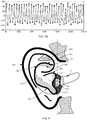
- FIG. 8A and FIG. 8B are schematic diagrams before and after a sample original electrical signal in a tragus inner-side region according to the eighth embodiment of the present application. As illustrated in FIG. 8A and FIG. 8B , variations of the original electrical signal are relatively stable, and quality of the electrical signal is high. Accordingly, the arterial branches, the vein branches and the flatness in the inner-side region of the tragus 212 are conditions for determining the detection surface.
- FIG. 9 is a schematic diagram of wearing an earphone on the ear according to the ninth embodiment of the present application.
- the light receiving unit 102 and the light emitting unit 101 are attached to an inner-side region of the tragus 212.
- a reference line R may be defined, and when attaching the light receiving unit 102 and the light emitting unit 101 to the inner-side region of the tragus 212, geometric centers of the light receiving unit 102 and the light emitting unit 101 are located on the reference line R. Since the arterial branches and the vein branches are densely distributed in the inner-side region of the tragus 212 and the flatness is good, the light receiving unit 102 and the light emitting unit 101 may be seamlessly attached to the inner-side region of the tragus 212.
- the light receiving unit 102 and the light emitting unit 101 may be integrated at a shell attached to the inner-side region of the tragus 212 after the earphone is worn, with no need to arrange an assistance mechanism, such that the biological feature detection apparatus including the light receiving unit 102 and the light emitting unit 101 are integrally tightly attached to the inner-side region of the tragus.
- FIG. 10 is a schematic diagram of wearing an earphone on the ear according to the tenth embodiment of the present application.
- the light receiving unit 102 and the light emitting unit 101 are attached to the inner-side region of the tragus, the specific position to which the receiving unit 102 and the light emitting unit 101 are attached in the inner-side region of the tragus 212 is distal from the outer ear canal entrance.
- the light receiving unit 102 and the light emitting unit 101 may be seamlessly attached to the inner-side region of the tragus 212.
- the light receiving unit 102 and the light emitting unit 101 may be integrated at a shell attached to the inner-side region of the tragus 212 after the earphone is worn, with no need to arrange an assistance mechanism, such that the biological feature detection apparatus including the light receiving unit 102 and the light emitting unit 101 are integrally tightly attached to the inner-side region of the tragus.
- FIG. 11 is a schematic diagram of wearing an earphone on the ear according to the eleventh embodiment of the present application.
- the light receiving unit 102 is attached to the inner-side region of the tragus, and the light emitting unit 101 is further located in a connection region between the intertragic notch and the outer ear cannel entrance and is also attached to a feature region enclosed by the tragus, the antitragus and the intertragic notch.
- the light receiving unit 102 and the light emitting unit 101 may be seamlessly attached to the ear.
- the light emitting unit 101 is attached to the intertragic notch, and the light receiving unit 102 is further located in the connection region between the intertragic notch and the outer ear canal entrance and is located in the feature region enclosed by the tragus, the antitragus and the intertragic notch.
- the light receiving unit 102 and the light emitting unit 101 may be integrated at a shell attached to the inner-side region of the tragus 212 and at a shell attached to the connection region between the intertragic notch and the outer ear canal entrance after the earphone is worn, with no need to arrange an assistance mechanism, such that the biological feature detection apparatus including the light receiving unit 102 and the light emitting unit 101 are integrally tightly attached to ear.
- FIG. 12 is a schematic diagram of wearing an earphone on the ear according to the twelfth embodiment of the present application.
- the light emitting unit 101 and the light receiving unit 102 are both located in the connection region between the intertragic notch and the outer ear canal entrance, and are also located in the feature region enclosed by the tragus, the antitragus and the intertragic notch.
- the light receiving unit 102 and the light emitting unit 101 may be integrated at a shell attached to the connection region between the intertragic notch and the outer ear canal entrance after the earphone is worn, with no need to arrange an assistance mechanism, such that the biological feature detection apparatus including the light receiving unit 102 and the light emitting unit 101 are integrally tightly attached to the inner-side region of the tragus.
- FIG. 13 is a schematic diagram of wearing an earphone on the ear according to the thirteenth embodiment of the present application. As illustrated in FIG. 13 , the light receiving unit 102 and the light emitting unit 101 are attached to a region between the inferior crus of antihelix and the crus of helix.
- the earphone may further include: a wearing assistance mechanism 110.
- the light receiving unit 102 and the light emitting unit 101 are arranged on the wearing assistance mechanism 101, such that the light receiving unit 102 and the light emitting unit 101 are attached to the region between the inferior crus of antihelix and the crus of helix.
- the light receiving unit 102 and the light emitting unit 101 are attached to a region between the antihelix and the crus of helix.
- the wearing assistance mechanism 110 may also be detached from the earphone, such that the wearing assistance mechanism 110 is assembled to the earphone where biological feature detection is desired, and is detached from the earphone where biological feature detection is not desired. In this way, the earphone and the wearing assistance mechanism 110 may flexibly cooperate with each other.
- one end of the wearing assistance mechanism 110 may be fixed to the shell of the earphone, and the other end of the wearing assistance mechanism 110 is connected to the light receiving unit 102 and the light emitting unit 101.
- FIG. 14 is a schematic diagram of wearing an earphone on the ear according to the fourteenth embodiment of the present application.
- the light receiving unit 102 and the light emitting unit 101 are both attached to a region of the cimba concha; in another embodiment, either the light receiving unit 102 or the light emitting unit 101 is attached to the region of the cimba concha.
- biological feature detection is carried out based on the light reflection theory.
- the position of the light receiving unit 102 or the light emitting unit 101 may be correspondingly adjusted to carry out biological feature detection based on the light projection theory.
- the light receiving unit 102 is attached to the region of the cimba concha
- the light emitting unit 101 is attached to a behind-the-ear region corresponding to the region of the cimba concha. Accordingly, biological feature detection may be carried out based on the light projection theory.
- FIG. 15 is a schematic diagram of wearing an earphone on the ear according to the fifteenth embodiment of the present application.
- the light receiving unit 102 and the light emitting unit 101 are both attached to a region of the earlobe.
- the light receiving unit 102 and the light emitting unit 101 are arranged on the same side of the region of the earlobe. Accordingly, biological feature detection may be carried out based on the light projection theory.
- FIG. 16 a schematic diagram of wearing an earphone on the ear according to the sixteenth embodiment of the present application is given.
- FIG. 17 is a schematic diagram of wearing an earphone on the ear according to the seventeenth embodiment of the present application.
- three pairs of light emitting units 101 and light receiving units 102 are arranged on the earphone.
- three pairs of light emitting unit 101 and light receiving unit 102 are respectively arranged in the inner-side region of the tragus, in the region between the inferior crus of helix and the crus of helix and in the region of the concha cavity.
- FIG. 18 is a schematic diagram of wearing an earphone on the ear according to the eighteenth embodiment of the present application.
- an elastic unit 109 is additionally arranged.
- the elastic unit 109 enables the light emitting unit 101 and the light receiving unit 102 to be tightly attached to the detection surface of the ear.
- the elastic unit 109 is arranged in a peripheral region of the ear distal from the outer ear canal entrance, such that the light emitting unit 101 and the light receiving unit 102 are pressed and thus are tightly attached to the detection surface of the ear.
- the elastic unit 109 may only press the light emitting unit 101 and the light receiving unit 102, such that the pressed light emitting unit 101 or the pressed light receiving unit 102 is tightly attached to the detection surface of the ear.
- the light emitting unit 101 and/or the light receiving unit 102 may still be tightly attached to the detection surface of the ear. This may prevent the biological feature detection apparatus from sliding relative to the detection surface, such that stability and strength of the detection signal are improved. In addition, this also mitigates or eliminates adverse impacts caused by the movement to the signal-to-noise ratio of the detection signal, and further improves the signal-to-noise ratio of the original electrical signal.
- the elastic unit 109 may be made of a soft silicone material.
- the elastic unit 109 may be specifically arranged inside the shell of the earphone.
- FIG. 19 is a schematic diagram of a connection region between an intertragic notch and an outer ear canal entrance according to the nineteenth embodiment of the present application. As illustrated in FIG. 19 , a plurality of connection lines are presented in the connection region between the intertragic notch and the outer ear canal entrance, which is also referred to as formation of a connection cluster. During arrangement of the light emitting unit or the light receiving unit, the light emitting unit or the light receiving unit may be specifically arranged on any connection line in the connection cluster.
- the light emitter may be specifically practiced by an LED lamp or a LED tube
- the light receiver may be specifically practiced by a photodiode
- the above described device embodiments are merely for illustration purpose only.
- the modules which are described as separate components may be physically separated or may be not physically separated, and the components which are illustrated as modules may be or may not be physical modules, that is, the components may be located in the same position or may be distributed into a plurality of network modules.
- a part or all of the modules may be selected according to the actual needs to achieve the objectives of the technical solutions of the embodiments. Persons of ordinary skill in the art may understand and implement the present application without paying any creative effort.
Landscapes
- Health & Medical Sciences (AREA)
- Life Sciences & Earth Sciences (AREA)
- Physics & Mathematics (AREA)
- Molecular Biology (AREA)
- Animal Behavior & Ethology (AREA)
- Pathology (AREA)
- Engineering & Computer Science (AREA)
- Biomedical Technology (AREA)
- Heart & Thoracic Surgery (AREA)
- Medical Informatics (AREA)
- Veterinary Medicine (AREA)
- Surgery (AREA)
- Biophysics (AREA)
- General Health & Medical Sciences (AREA)
- Public Health (AREA)
- Cardiology (AREA)
- Otolaryngology (AREA)
- Physiology (AREA)
- Measurement Of The Respiration, Hearing Ability, Form, And Blood Characteristics Of Living Organisms (AREA)
- Measuring Pulse, Heart Rate, Blood Pressure Or Blood Flow (AREA)
- Spectroscopy & Molecular Physics (AREA)
- Optics & Photonics (AREA)
Abstract
Description
- This application is based upon and claims priority to Chinese Patent Application
PCT/CN2017/091042 - Embodiments of the present application relate to the technical field of biological feature detection, and in particular, relate to a biological feature detection apparatus and an electronic terminal.
- Rapid development of smart devices, for example, emergence of smart phones, smart bracelets, smart earphones and the like, facilitates practice of applications having a healthcare function, for example, detection of heart rate, blood oxygen and the like biological features. Specifically, these smart devices are used in scenarios of monitoring the heart rate and blood oxygen during exercise or movement to judge whether the biological feature of a user is normal, or monitoring the heart rate and blood oxygen during sleeping to judge whether the biological feature of a user is normal.
- With regard to the practice of the above applications having the healthcare function, the current commonly used manner is: measuring the biological feature based on the optical theory, for example, the light reflection theory and the light projection theory. Using the light reflection theory as an example, the light emitted by a light emitter is incident to the biological tissue and then reflected by the biological tissue, and a light receiver receives the reflected light and performs biological feature detection based on the reflected light. During this process, the incident light is reflected under effects (absorption and diffusion) of the blood in the tissue and then the reflected light is formed. Since the blood in the tissue may be periodically changed, the biological feature may be obtained by sensing and analyzing the reflected light. Analogously, with respect to the light projection theory, the biological feature may be obtained by sensing and analyzing the projected light.
- In the prior art, using biological feature detection practiced based on the light reflection theory as an example, the relative position between the light emitter and the light receiver is generally constant. Therefore, accurate monitoring of the biological feature may not be achieved by adjusting the relative position between the light emitter and the light receiver.
- Embodiments of the present application are intended to provide a biological feature detection apparatus and an electronic terminal, to at least solve the above technical problem in the prior art.
- To achieve the objective of embodiments of the present application, embodiments of the present application provide a biological feature detection apparatus. The detection apparatus includes a light emitting unit and a light receiving unit. The light emitting unit is configured to emit light to a detection surface of a biological tissue, wherein the light emitted by the light emitting unit is processed by the biological tissue and then transmitted to the light receiving unit, the light receiving unit is configured to receive the light and perform a photoelectric conversion to generate an original electrical signal for biological feature detection, and the relative position and/or the relative angleadjustable is defined between the light emitting unit and the light receiving unit.
- Optionally, in an embodiment of the present application, the light emitting unit is arranged on a first substrate, and the light receiving unit is arranged on a second substrate.
- Optionally, in an embodiment of the present application, the detection apparatus further includes: a flexible member. The flexible member is connected to the first substrate and the second substrate respectively via a solder pad or a plug, such that the relative position and/or the relative angleadjustable is defined between the light emitting unit and the light receiving unit.
- Optionally, in an embodiment of the present application, the first substrate and the second substrate have a multilayer structure; and correspondingly, the detection apparatus further comprises: a flexible member. At least one end of the flexible member is embedded into the multilayer structures of the first substrate and/or the second substrate to be connected to the first substrate and/or the second substrate respectively, such that the relative position and/or the relative angle adjustable is defined between the light emitting unit and the light receiving unit.
- Optionally, in an embodiment of the present application, the first substrate and the second substrate have a multilayer structure. Any layer in the multilayer structure of the first substrate is made of a flexible material and extends outside to the second substrate and connected to any layer in the multilayer structure of the second substrate; or any layer in the multilayer structure of the second substrate is made of a flexible material and extends outside to the first substrate and connected to any layer in the multilayer structure of the first substrate, such that the relative position and/or the relative angleadjustable is defined between the light emitting unit and the light receiving unit.
- Optionally, in an embodiment of the present application, the apparatus further includes: an optical shielding unit, configured to shield or absorb the light emitted by the light emitting unit to prevent the light emitted by the light emitting light from being directly transmitted to the light receiving unit without being processed by the biological tissue; and/or further comprising: a light guiding unit, configured to guide the light emitted by the light emitting unit to the detection surface of the biological tissue, and/or configured to guide the light being processed by the biological tissue to the light receiving unit.
- Optionally, in an embodiment of the present application, the optical shielding unit and the light guiding unit are integrally arranged, or the optical shielding unit and the light guiding unit are separately arranged.
- Optionally, in an embodiment of the present application, the light emitting unit and the light receiving unit are both provided with the light guiding unit. The light guiding unit on the light emitting unit and the light guiding unit on the light receiving unit are integrally arranged or separately arranged.
- Optionally, in any embodiment of the present application, a surface shape of the light guiding unit and/or the optical shielding unit matches a shape of the detection surface of the biological tissue.
- Optionally, in an embodiment of the present application, the apparatus further includes: a processing circuit, wherein the processing circuit is configured to perform an analog-to-digital conversion for the original electrical signal to form a digital signal and filters the digital signal; and/or further comprising: a control circuit, wherein the control circuit is configured to control the light emitting unit to emit light to the biological tissue.
- Optionally, in an embodiment of the present application, the apparatus further includes: a processor; wherein the processor is configured to perform biological feature detection according to the original electrical signal.
- Optionally, in an embodiment of the present application, the relative position is a linear distance between a geometric center of the light emitting unit and a geometric center of the light receiving unit, and the relative angle is a normal angle between a planar surface of the light emitting unit and a planar surface of the light receiving unit.
- Optionally, in an embodiment of the present application, the biological feature is a heart rate feature and a blood oxygen feature based on a photoplethysmogram signal.
- Optionally, in an embodiment of the present application, the biological tissue is an ear, and during biological feature detection, the light receiving unit and/or the light emitting unit is configured to attach to a tragus inner-side region of the ear; or the light receiving unit and/or the light emitting unit is configured to attach to a region between an inferior crus of antihelix and a crus of helix of the ear; or the light receiving unit and/or the light emitting unit is configured to attach to a region between an antihelix and a crus of helix of the ear; or the light receiving unit and/or the light emitting unit is configured to attach to a cimba concha region of the ear; or the light receiving unit and/or the light emitting unit is configured to attach to an earlobe region of the ear; or the light receiving unit and/or the light emitting unit is located in a concha cavity of the ear; or the light receiving unit and/or the light emitting unit is located in a region enclosed by the crus of helix, an ear canal entrance and the antihelix close to an antitragus of the ear.
- Optionally, in an embodiment of the present application, when the light receiving unit is attached to the tragus inner-side region, the light emitting unit is located in an underneath connection region between an intertragic notch and an outer ear canal entrance; or the light emitting unit is configured to attach to the tragus inner-side region, the light receiving unit is located in an underneath connection region between an intertragic notch and an outer ear canal entrance.
- Optionally, in any embodiment of the present application, the apparatus further includes: a wearing assistance mechanism; wherein the light receiving unit and the light emitting unit are arranged on the wearing assistance mechanism, such that the light receiving unit and the light emitting unit is arranged in the region between the inferior crus of antihelix and the crus of helix or such that the light receiving unit and the light emitting unit is arranged in the region between the antihelix and the crus of helix.
- Optionally, in any embodiment of the present application, the apparatus further includes: an elastic unit; wherein, during biological feature detection, the elastic unit is configured to enable the light emitting and the light receiving unit to be tightly attached to the biological tissue.
- Embodiments of the present application further provide an electronic terminal. The electronic terminal includes the biological feature detection apparatus as described in any one of the above embodiments.
- In the biological feature detection apparatus according to embodiments of the present application, the light emitting unit is configured to emit light to a detection surface of a biological tissue, wherein the light emitted by the light emitting unit is processed by the biological tissue and then transmitted to the light receiving unit, the light receiving unit is configured to receive the light and perform a photoelectric conversion to generate an original electrical signal for biological feature detection, and the relative position and/or the relative angleadjustable is defined between the light emitting unit and the light receiving unit. As such, accurate monitoring of the biological feature is achieved.
-
-
FIG. 1 is a schematic structural diagram of a biological feature detection apparatus according to the first embodiment of the present application; -
FIG. 2 is a schematic structural diagram of a biological feature detection apparatus according to the second embodiment of the present application; -
FIG. 3 is a schematic structural diagram of a biological feature detection apparatus according to the third embodiment of the present application; -
FIG. 4 is a schematic structural diagram of a biological feature detection apparatus according to the fourth embodiment of the present application; -
FIG. 5 is a schematic structural diagram of a biological feature detection apparatus according to the fifth embodiment of the present application; and -
FIG. 6 is a schematic structural diagram of a biological feature detection apparatus according to the sixth embodiment of the present application; -
FIG. 7 is a schematic diagram of candidate regions of a detection surface of an ear according to the seventh embodiment of the present application; -
FIG. 8A andFIG. 8B are schematic diagrams before and after a sample detection signal is filtered in a tragus inner-side region according to the eighth embodiment of the present application; -
FIG. 9 is a schematic diagram of wearing an earphone on the ear according to the ninth embodiment of the present application; -
FIG. 10 is a schematic diagram of wearing an earphone on the ear according to the tenth embodiment of the present application; -
FIG. 11 is a schematic diagram of wearing an earphone on the ear according to the eleventh embodiment of the present application; -
FIG. 12 is a schematic diagram of wearing an earphone on the ear according to the twelfth embodiment of the present application; -
FIG. 13 is a schematic diagram of wearing an earphone on the ear according to the thirteenth embodiment of the present application; -
FIG. 14 is a schematic diagram of wearing an earphone on the ear according to the fourteenth embodiment of the present application; -
FIG. 15 is a schematic diagram of wearing an earphone on the ear according to the fifteenth embodiment of the present application; -
FIG. 16 is a schematic diagram of wearing an earphone on the ear according to the sixteenth embodiment of the present application; -
FIG. 17 is a schematic diagram of wearing an earphone on the ear according to the seventeenth embodiment of the present application; -
FIG. 18 is a schematic diagram of wearing an earphone on the ear according to the eighteenth embodiment of the present application; and -
FIG. 19 is a schematic diagram of a connection line between an intertragic notch and an outer ear canal entrance according to the nineteenth embodiment of the present application. - Practice of the present application is described in detail with reference to drawings and specific embodiments, such that the practice of addressing the technical problem using the technical means according to the present application and achieving the technical effects may be better understood and conducted.
- In the biological feature detection apparatus according to embodiments of the present application, the light emitting unit is configured to emit light to a detection surface of a biological tissue, wherein the light emitted by the light emitting unit is processed by the biological tissue and then transmitted to the light receiving unit, the light receiving unit is configured to receive the light and perform a photoelectric conversion to generate an original electrical signal for biological feature detection, and the relative position and/or the relative angleadjustable is defined between the light emitting unit and the light receiving unit. As such, accurate monitoring of the biological feature is achieved.
-
FIG. 1 is a schematic structural diagram of a biological feature detection apparatus according to the first embodiment of the present application. In this embodiment, a biologicalfeature detection apparatus 1 is also referred to as a biological feature detection apparatus. Specifically, the biological feature detection apparatus includes alight emitting unit 101 and alight receiving unit 102. Thelight emitting unit 101 is configured to emit light to a detection surface of a biological tissue, and thelight receiving unit 102 is configured to receive the light and perform a photoelectric conversion to generate an original electrical signal for biological feature detection. - Optionally, in this embodiment, the biological feature detection apparatus may further include a
hard substrate 103. Thelight emitting unit 101 and thelight receiving unit 102 are both arranged on thehard substrate 103. - Optionally, in this embodiment, the biological feature detection apparatus may further include: an
optical shielding unit 104, configured to shield or absorb the light emitted by the light emitting unit to prevent the light emitted by the light emitting light from being directly transmitted to the light receiving unit without being processed by the biological tissue, and hence to improve accuracy of biological feature detection. - Optionally, in this embodiment, the biological feature detection apparatus may further include: a
light guiding unit 105, configured to guide the light emitted by the light emitting unit to the detection surface of the biological tissue, and/or configured to guide the light being processed by the biological tissue to the light receiving unit. Specifically, alight guiding unit 105 may be arranged on each of thelight emitting unit 101 and thelight receiving unit 102. That is, the biological feature detection apparatus includes twolight guiding units 105. The twolight guiding units 105 may be integrally arranged or separately arranged. That is, thelight guiding unit 105 on thelight emitting unit 101 and thelight guiding unit 105 on thelight receiving unit 102 may be integrally arranged or separately arranged. However, it should be noted that alight guiding unit 105 may also be arranged on either thelight emitting unit 101 or thelight receiving unit 102. That is, the biological feature detection apparatus includes onelight guiding unit 105. In this embodiment, thelight guiding unit 105 improves efficiency of light transmission, lowers entire power consumption of the apparatus and improves detection accuracy. - Specifically, when the
optical shielding unit 104 and thelight guiding unit 105 are both arranged on the biological feature detection apparatus, theoptical shielding unit 104 and thelight guiding unit 105 are integrally arranged, or theoptical shielding unit 104 and thelight guiding unit 105 are separately arranged. - In this embodiment, surfaces, facing toward the detection surface, of the
light guiding unit 105 and theoptical shielding unit 104 are defined to match with the detection surface of the biological tissue. If the detection surface is a planar surface, the surfaces, facing toward the detection surface, of thelight guiding unit 105 and theoptical shielding unit 104 are also planar surfaces; if the detection surface is an arc surface, the surfaces, facing toward the detection surface, of thelight guiding unit 105 and theoptical shielding unit 104 are also arc surfaces; and if the detection surface is an irregular surface, the surfaces, facing toward the detection surface, of thelight guiding unit 105 and theoptical shielding unit 104 are also irregular curved surfaces. It should be noted that the surface of thelight guiding unit 105 or theoptical shielding unit 104 that faces toward the detection surface, may be shaped to match the detection surface of the biological tissue according to the structure design needs. - In another embodiment, based on the embodiment illustrated in
FIG. 1 , the biological feature detection apparatus may further include a processing circuit. The processing circuit is configured to perform an analog-to-digital conversion for the original electrical signal to form a digital signal and filter the digital signal; and/or further comprising: a control circuit, wherein the control circuit is configured to control the light emitting unit to emit light to the biological tissue. - It should be noted that functionality of the processing circuit may be extended according to the actual needs, which is not limited to analog-to-digital conversion and filter processing.
- In another embodiment, based on the embodiment illustrated in
FIG. 1 , the biological feature detection apparatus may further include a processor. The processor is configured to perform biological feature detection according to the original electrical signal. During biological feature detection performed by the processor according to the original electrical signal, a biological feature signal may be specifically extracted from a digital signal experiencing analog-to-digital conversion and filter processing by the processing circuit; or the processor directly performs analog-to-digital conversion and filtering for the original electrical signal, and then performs biological feature detection. It should be noted that the processor may be an independently configured microprocessor, or may be the processor of the terminal connected to the earphone. -
FIG. 2 is a schematic structural diagram of a biological feature detection apparatus according to the second embodiment of the present application. As illustrated inFIG. 2 , in this embodiment, using an exploded schematic diagram as an example, like the embodiment illustrated inFIG. 1 , the biological feature detection apparatus likewise includes: alight emitting unit 101 and alight receiving unit 102. Different from the above embodiment, the biological feature detection apparatus further includes: a flexible member and two substrates. The two substrates are respectively afirst substrate 107 and asecond substrate 108. Thelight emitting unit 101 is arranged on thefirst substrate 107, and thelight receiving unit 102 is arranged on thesecond substrate 108. In this embodiment, thefirst substrate 107 and thesecond substrate 108 are both hard substrates, and theflexible member 106 is a flexible circuit board. The hard substrate may be, for example, a PCB, a hybrid board of a FPC and a reinforcement board or the like structure that may not be bent; and the flexible circuit board may be, for example, an FPC, an FFC, a set of electrical connectors or the like structure that may be bent. - It should be noted that, alternatively, the
light emitting unit 101 and thelight receiving unit 102 may also be arranged on the same rigid substrate or flexible substrate. - In this embodiment, the
light emitting unit 101 is approximately a columnar light source, and thelight receiving unit 102 is approximately a planar array to receive the light with a greater light sensing area as much as possible. - In this embodiment, the
light emitting unit 101 and thelight receiving unit 102 are connected (including, but not limited to, physical connection and/or electrical connection) to each other via theflexible member 106. The flexible member is configured to adjust a relative position and/or a relative angle between thelight emitting unit 101 and thelight receiving unit 102. - Optionally, in this embodiment, the relative position is a linear distance between a geometric center of the
light emitting unit 101 and a geometric center of thelight receiving unit 102, and/or the relative angle is a normal angle between an outer surface of thelight emitting unit 101 and an outer surface of thelight receiving unit 102. - Optionally, in any embodiment of the present application, a normal of the
light receiving unit 102 facing towards an outer surface of the detection surface is parallel to a normal of the detection surface; and/or a normal of thelight emitting unit 101 facing towards an outer surface of the detection surface is parallel to a normal of the detection surface. - It should be noted that, alternatively, either the first substrate or the second substrate is a flexible substrate, or the first substrate and the second substrate are both flexible substrates. Further, the flexible member may be a partial structure of the flexible substrate.
- In another embodiment, the
light emitting unit 101 and thelight receiving unit 102 may be separately arranged from the processing circuit in terms of physical aspect, or may be integrally arranged with the processing circuit, the control circuit and the processor. - In another embodiment, the
light emitting unit 101, thelight receiving unit 102, the processing circuit and the MCU are physically separate structures, or may be integrated to form a chip structure. - In another embodiment, the biological feature detection apparatus may include a plurality of light emitting units and one light receiving unit, to improve emission efficiency of light.
- In another embodiment, the biological feature detection apparatus may include a plurality of light receiving units and one light emitting unit, to improve reception efficiency of light.
- In the above embodiment including the flexible member, due to presence of the flexible member, the relative position and the relative angle between the light emitting unit and the light receiving unit may be randomly adjusted, such that the biological feature detection apparatus is suitable for the detection surface having any shape, and quality of the original electrical signal is improved.
- In addition, when the embodiment illustrated in
FIG. 2 is applied to the specific product of the earphone, the adjustability of the relative position and the relative angle between the light emitting unit and the light receiving unit enables the entire earphone product to have a relatively compact structure. -
FIG. 3 is a schematic structural diagram of a biological feature detection apparatus according to the third embodiment of the present application. As illustrated inFIG. 3 , this embodiment emphasizes the connection of the flexible member inFIG. 2 to the first substrate and the second substrate inFIG. 2 as an independent structure member. - In this embodiment, with respect to the
light emitting unit 101 and thelight receiving unit 102, a driving circuit and a detecting circuit need to be respectively configured. During circuit design, the driving circuit and the detecting circuit are generally integrated in a control chip. The control chip, as an entirety, may be disposed on the side of thefirst substrate 107 where thelight emitting unit 101 is arranged or the side of thesecond substrate 108 where thelight receiving unit 102 is arranged. As such, the detecting circuit of thelight receiving unit 102 and thelight receiving unit 102 may not be arranged on the same substrate, that is, thesecond substrate 108; or the driving circuit of thelight emitting unit 101 and thelight emitting unit 101 may not be arranged on the same substrate, that is, thefirst substrate 107. Considering that the detecting circuit of thelight receiving unit 102 and thelight receiving unit 102 may not be arranged on the same substrate or the driving circuit of thelight emitting unit 101 and thelight emitting unit 101 may not be arranged on the same substrate, in this embodiment, since theflexible member 106 is an independent structure member that is absolutely independent of the first substrate and the second substrate, and electrical connection lines are configured, during connection to the first substrate and the second substrate, thelight receiving unit 102 and the detecting circuit thereof, or thelight emitting unit 101 and the driving circuit thereof are ensured to collaboratively work. For example, if thelight receiving unit 102 and the detecting circuit thereof are not arranged on the same substrate, the detecting circuit and thelight receiving unit 102 may communicate with each other via the electrical connection lines in theflexible member 106. Therefore, theflexible member 106 is connected to the first substrate and the second substrate respectively via a first plug 107-1 and a second plug 108-1, and the relative position and/or the relative angleadjustable is defined between the light emitting unit and the light receiving unit. - In another embodiment, the first plug 107-1 and the second plug 108-1 may also be replaced by a solder pad.
-
FIG. 4 is a schematic structural diagram of a biological feature detection apparatus according to the fourth embodiment of the present application. Different from the embodiment as illustrated inFIG. 2 or FIG. 3 , thefirst substrate 107 and thesecond substrate 108 have a multilayer structure. Two ends of the flexible member are respectively embedded into the multilayer structures of the first substrate and the second substrate to be respectively connected to the first substrate and the second substrate. For example, since the structure of the flexible member is a double-layer structure made of a flexible material, and two up-down adjacent layers in the multilayer structures of the first substrate and the second substrate is made of a flexible material (that is, the first substrate and the second substrate are flexible-hard hybrid boards), during manufacture, the two ends of theflexible member 106 are directly interconnected to the two adjacent layers made of the flexible material in the first substrate and the second substrate, and are laminated with the other layers in the first substrate. In addition, for practice of the electrical connection, a region where the flexible member is laminated with the other layers is provided with a via to practice the electrical connection, which is equivalent to replacement of the plug or the solder pad. - In this embodiment, the case where the
first substrate 107 and thesecond substrate 108 are each a PCB having a four-layer structure is used as an example. Specifically, thefirst substrate 107 includes four layers from top to bottom: afirst layer PCB 107a, asecond layer PCB 107b, athird layer PCB 107c and afourth layer PCB 107d; and thesecond substrate 108 includes four layers from top to bottom: afirst layer PCB 108a, asecond layer PCB 108b, athird layer PCB 108c and afourth layer PCB 108d. - Specifically, the
second layer PCB 107b and thethird layer PCB 107c correspond to the double-layer structure in theflexible member 106. Therefore, one end of theflexible member 106 is sandwiched between thefirst layer PCB 107a and thefourth PCB 107d in thefirst substrate 107. Likewise, the other end of theflexible member 106 is sandwiched between thefirst layer PCB 108a and thefourth PCB 108d in thesecond substrate 108. -
FIG. 5 is a schematic structural diagram of a biological feature detection apparatus according to the fifth embodiment of the present application. As illustrated inFIG. 5 , relative to the embodiment illustrated inFIG. 4 , in this embodiment, one end of theflexible member 106 is selectively laminated to thefirst substrate 107, such that one end of theflexible member 106 is embedded into thefirst substrate 107; and the other end of theflexible member 106 is connected to the first substrate via the second plug 108-1. Accordingly, thefirst substrate 107 may be a flexible-hard hybrid board, and thesecond substrate 108 is a hard substrate. - Description is given by using the case where the
first substrate 107 is a four-layer structure as an example, that is, thefirst substrate 107 includes four layers from top to bottom: afirst layer PCB 107a, asecond layer PCB 107b, athird layer PCB 107c and afourth layer PCB 107d. Thesecond layer PCB 107b and thethird layer PCB 107c correspond to the double-layer structure in theflexible structure 106. In addition, one end of theflexible member 106 is sandwiched between thefirst layer PCB 107a and thefourth layer PCB 107d in thefirst substrate 107, and the other end of theflexible member 106 is connected to thesecond substrate 108 via the second plug 108-1. - It should be noted that in the above embodiment, the numbers of the structure layers of the
first substrate 107 and thesecond substrate 108 in the embodiments stated above are only exemplary, and in practice, thefirst substrate 107 and thesecond substrate 108 may also have a 6-layer structure or 8-layer structure. - In addition, reference may also be made to the embodiment illustrate din
FIG. 5 , or made to the manner of embedding the flexible member into the first substrate. One end of the flexible member inFIG. 5 is connected to the first substrate via a plug, and the other end of the flexible member is embedded into the second substrate. - It should be noted that the above lamination treatment is merely one optional way for embedding the flexible member into the first substrate, and a person skilled in the art would employ other alternative ways under teaching given by the present application.
- Nevertheless, in another embodiment, if the first substrate and the second substrate are both substrates having a multilayer structure, any layer in the multilayer structure of the first substrate is made of a flexible material and extends outside to the second substrate and connected to any layer in the multilayer structure of the second substrate; or any layer in the multilayer structure of the second substrate is made of a flexible material and extends outside to the first substrate and connected to any layer in the multilayer structure of the first substrate, such that the the relative position and/or the relative angleadjustable is defined between the light emitting unit and the light receiving unit.
-
FIG. 6 is a schematic structural diagram of a biological feature detection apparatus according to the sixth embodiment of the present application. In this embodiment, a biologicalfeature detection apparatus 1 is practiced in the form of an earphone, which may also be understood as integrating the biological feature detection apparatus on an earphone structure. For clear description of application of the biological feature detection apparatus,FIG. 1 also illustratively shows anear 2 as the biological tissue. If the biological feature detection is practiced by using the earphone structure, a position relationship between the light emitting unit and the light receiving unit, and the detection surface on the ear is as described in the embodiments hereinafter. When the detection surface is at the following positions, few modifications are made to the structure of the traditional earphone, and the earphone may be comfortably worn. -
FIG. 7 is a schematic diagram of candidate regions of a detection surface of an ear according to the seventh embodiment of the present application. As illustrated inFIG. 2 , corresponding toFIG. 6 , a portion of the features of theear 2 include: ahelix 201, anantihelix 202, anauricular concha 203, anantitragus 204, atriangular fossa 205, an inferior crus ofantihelix 206, acimba concha 207, a crus ofhelix 208, asupratragic notch 209, an outerear canal entrance 210, anear canal 211, atragus 212, and anintertragic notch 213. - In the embodiments hereinafter, description is given by using the scenario where the biological feature detection apparatus is practiced with the earphone as a specific product. To better determine the detection surface in a feature region of the ear as illustrated in
FIG. 7 , after the arterial branches, the vein branches and flatness of different feature regions of the ear are comprehensively analyzed, and a relatively flat feature region where the arterial branch density and the vein branch density are great is used as the detection surface. - Accordingly, in the embodiments hereinafter, exemplarily, the light emitting unit and/or the light receiving unit are arranged in an inner side region of the
tragus 211, or in a connection line between theintertragic notch 212 and the outerear canal entrance 210, a concha cavity region of theauricular concha 203, a region extending to thesupratragic notch 209, a region between the inferior crus of antihelix 206 (or the antihelix 202) and the crus ofhelix 208, a region of theauricular concha 203, a region of the cimba concha 207, a region of the earlobe (not illustrated in the drawings); or the light emitting unit and/or the light receiving unit is arranged in a region enclosed by the crus of helix, the ear canal entrance and the antihelix close to the antitragus. For different users, these regions are morphologically stable. That is, the biological feature detection apparatus has good compatibility with regard to the ears of different users, such that a detection signal having a high signal-to-noise ratio may be simply generated, and accuracy of biological feature detection is ensured. - In a specific embodiment, the light emitting unit and the light receiving unit are arranged in a region D enclosed by the crus of helix, the ear canal entrance and the antihelix close to the antitragus; the light emitting unit and the light receiving unit in the biological feature detection apparatus is tightly attached to the detection surface. Since the arterial branches and the vein branches are densely distributed at this position, the obtained original electrical signal has a great signal-to-noise ratio. Therefore, the original electrical signal has a strong anti-interference capability, and thus accuracy of biological feature detection is further ensured. In addition, since different ear shapes are slightly different in the region D, if the biological feature detection apparatus is integrated on an earphone, the earphone is well compatible with the ears. Therefore, the earphone has a wide application range, and thus achieves a high accuracy of signal detection for different users.
-
FIG. 8A andFIG. 8B are schematic diagrams before and after a sample original electrical signal in a tragus inner-side region according to the eighth embodiment of the present application. As illustrated inFIG. 8A andFIG. 8B , variations of the original electrical signal are relatively stable, and quality of the electrical signal is high. Accordingly, the arterial branches, the vein branches and the flatness in the inner-side region of thetragus 212 are conditions for determining the detection surface. -
FIG. 9 is a schematic diagram of wearing an earphone on the ear according to the ninth embodiment of the present application. As illustrated inFIG. 9 , in this embodiment, during biological feature detection, thelight receiving unit 102 and thelight emitting unit 101 are attached to an inner-side region of thetragus 212. Specifically, a reference line R may be defined, and when attaching thelight receiving unit 102 and thelight emitting unit 101 to the inner-side region of thetragus 212, geometric centers of thelight receiving unit 102 and thelight emitting unit 101 are located on the reference line R. Since the arterial branches and the vein branches are densely distributed in the inner-side region of thetragus 212 and the flatness is good, thelight receiving unit 102 and thelight emitting unit 101 may be seamlessly attached to the inner-side region of thetragus 212. - In this embodiment, to enable the
light receiving unit 102 and thelight emitting unit 101 to be attached to the inner-side region of thetragus 212, thelight receiving unit 102 and thelight emitting unit 101 may be integrated at a shell attached to the inner-side region of thetragus 212 after the earphone is worn, with no need to arrange an assistance mechanism, such that the biological feature detection apparatus including thelight receiving unit 102 and thelight emitting unit 101 are integrally tightly attached to the inner-side region of the tragus. -
FIG. 10 is a schematic diagram of wearing an earphone on the ear according to the tenth embodiment of the present application. As illustrated inFIG. 10 , in this embodiment, like the ninth embodiment illustrated inFIG. 9 , although during biological feature detection, thelight receiving unit 102 and thelight emitting unit 101 are attached to the inner-side region of the tragus, the specific position to which the receivingunit 102 and thelight emitting unit 101 are attached in the inner-side region of thetragus 212 is distal from the outer ear canal entrance. Since the arterial branches and the vein branches are densely distributed in the inner-side region of thetragus 212, and the flatness is good, thelight receiving unit 102 and thelight emitting unit 101 may be seamlessly attached to the inner-side region of thetragus 212. - In this embodiment, similar to the embodiment illustrated in
FIG. 9 , to enable thelight receiving unit 102 and thelight emitting unit 101 to be attached to the inner-side region of thetragus 212, thelight receiving unit 102 and thelight emitting unit 101 may be integrated at a shell attached to the inner-side region of thetragus 212 after the earphone is worn, with no need to arrange an assistance mechanism, such that the biological feature detection apparatus including thelight receiving unit 102 and thelight emitting unit 101 are integrally tightly attached to the inner-side region of the tragus. -
FIG. 11 is a schematic diagram of wearing an earphone on the ear according to the eleventh embodiment of the present application. As illustrated inFIG. 11 , in this embodiment, like the embodiment illustrated inFIG. 9 , during biological feature detection, thelight receiving unit 102 is attached to the inner-side region of the tragus, and thelight emitting unit 101 is further located in a connection region between the intertragic notch and the outer ear cannel entrance and is also attached to a feature region enclosed by the tragus, the antitragus and the intertragic notch. Since the arterial branches and the vein branches are densely distributed in the inner-side region of thetragus 212 and the connection region between the intertragic notch and the outer ear canal entrance, and the flatness is good, thelight receiving unit 102 and thelight emitting unit 101 may be seamlessly attached to the ear. - It should be noted that in another embodiment, the
light emitting unit 101 is attached to the intertragic notch, and thelight receiving unit 102 is further located in the connection region between the intertragic notch and the outer ear canal entrance and is located in the feature region enclosed by the tragus, the antitragus and the intertragic notch. - In this embodiment, similar to the embodiment illustrated in
FIG. 9 , to enable thelight receiving unit 102 and thelight emitting unit 101 to be tightly attached to the inner-side region of thetragus 212 and the connection region between the intertragic notch and the outer ear canal entrance, thelight receiving unit 102 and thelight emitting unit 101 may be integrated at a shell attached to the inner-side region of thetragus 212 and at a shell attached to the connection region between the intertragic notch and the outer ear canal entrance after the earphone is worn, with no need to arrange an assistance mechanism, such that the biological feature detection apparatus including thelight receiving unit 102 and thelight emitting unit 101 are integrally tightly attached to ear. -
FIG. 12 is a schematic diagram of wearing an earphone on the ear according to the twelfth embodiment of the present application. As illustrated inFIG. 12 , in this embodiment, thelight emitting unit 101 and thelight receiving unit 102 are both located in the connection region between the intertragic notch and the outer ear canal entrance, and are also located in the feature region enclosed by the tragus, the antitragus and the intertragic notch. - In this embodiment, similar to the embodiment illustrated in
FIG. 12 , to enable thelight receiving unit 102 and thelight emitting unit 101 to be tightly attached to the connection region between the intertragic notch and the outer ear canal entrance, thelight receiving unit 102 and thelight emitting unit 101 may be integrated at a shell attached to the connection region between the intertragic notch and the outer ear canal entrance after the earphone is worn, with no need to arrange an assistance mechanism, such that the biological feature detection apparatus including thelight receiving unit 102 and thelight emitting unit 101 are integrally tightly attached to the inner-side region of the tragus. -
FIG. 13 is a schematic diagram of wearing an earphone on the ear according to the thirteenth embodiment of the present application. As illustrated inFIG. 13 , thelight receiving unit 102 and thelight emitting unit 101 are attached to a region between the inferior crus of antihelix and the crus of helix. - In this embodiment, the earphone may further include: a wearing assistance mechanism 110. The
light receiving unit 102 and thelight emitting unit 101 are arranged on the wearingassistance mechanism 101, such that thelight receiving unit 102 and thelight emitting unit 101 are attached to the region between the inferior crus of antihelix and the crus of helix. - In another embodiment, as illustrated in
FIG. 13 , thelight receiving unit 102 and thelight emitting unit 101 are attached to a region between the antihelix and the crus of helix. - In another embodiment, the wearing assistance mechanism 110 may also be detached from the earphone, such that the wearing assistance mechanism 110 is assembled to the earphone where biological feature detection is desired, and is detached from the earphone where biological feature detection is not desired. In this way, the earphone and the wearing assistance mechanism 110 may flexibly cooperate with each other.
- During practice, one end of the wearing assistance mechanism 110 may be fixed to the shell of the earphone, and the other end of the wearing assistance mechanism 110 is connected to the
light receiving unit 102 and thelight emitting unit 101. -
FIG. 14 is a schematic diagram of wearing an earphone on the ear according to the fourteenth embodiment of the present application. As illustrated inFIG. 14 , in this embodiment, thelight receiving unit 102 and thelight emitting unit 101 are both attached to a region of the cimba concha; in another embodiment, either thelight receiving unit 102 or thelight emitting unit 101 is attached to the region of the cimba concha. - In the embodiments illustrated in
FIG. 9 to FIG. 14 , biological feature detection is carried out based on the light reflection theory. However, it should be noted that the position of thelight receiving unit 102 or thelight emitting unit 101 may be correspondingly adjusted to carry out biological feature detection based on the light projection theory. - In another embodiment, the
light receiving unit 102 is attached to the region of the cimba concha, and thelight emitting unit 101 is attached to a behind-the-ear region corresponding to the region of the cimba concha. Accordingly, biological feature detection may be carried out based on the light projection theory. -
FIG. 15 is a schematic diagram of wearing an earphone on the ear according to the fifteenth embodiment of the present application. As illustrated inFIG. 15 , thelight receiving unit 102 and thelight emitting unit 101 are both attached to a region of the earlobe. In this embodiment, thelight receiving unit 102 and thelight emitting unit 101 are arranged on the same side of the region of the earlobe. Accordingly, biological feature detection may be carried out based on the light projection theory. - In addition, if the
light receiving unit 102 and thelight emitting unit 101 are respectively arranged on two sides of the region of the earlobe, biological feature detection may be correspondingly carried out based on the light projection theory. Referring toFIG. 16 , a schematic diagram of wearing an earphone on the ear according to the sixteenth embodiment of the present application is given. -
FIG. 17 is a schematic diagram of wearing an earphone on the ear according to the seventeenth embodiment of the present application. As illustrated inFIG. 17 , different from the above embodiment, three pairs of light emittingunits 101 and light receivingunits 102 are arranged on the earphone. Specifically, as illustrated inFIG. 17 , three pairs oflight emitting unit 101 andlight receiving unit 102 are respectively arranged in the inner-side region of the tragus, in the region between the inferior crus of helix and the crus of helix and in the region of the concha cavity. -
FIG. 18 is a schematic diagram of wearing an earphone on the ear according to the eighteenth embodiment of the present application. As illustrated inFIG. 18 , in this embodiment, anelastic unit 109 is additionally arranged. During biological feature detection, theelastic unit 109 enables thelight emitting unit 101 and thelight receiving unit 102 to be tightly attached to the detection surface of the ear. In this embodiment, using the scenario where an elastic unit is added based on the embodiment illustrated inFIG. 8 as an example, as illustrated inFIG. 18 , theelastic unit 109 is arranged in a peripheral region of the ear distal from the outer ear canal entrance, such that thelight emitting unit 101 and thelight receiving unit 102 are pressed and thus are tightly attached to the detection surface of the ear. - Alternatively, in another embodiment, the
elastic unit 109 may only press thelight emitting unit 101 and thelight receiving unit 102, such that the pressedlight emitting unit 101 or the pressedlight receiving unit 102 is tightly attached to the detection surface of the ear. - In the embodiment including the
elastic unit 109, even in the movement, thelight emitting unit 101 and/or thelight receiving unit 102 may still be tightly attached to the detection surface of the ear. This may prevent the biological feature detection apparatus from sliding relative to the detection surface, such that stability and strength of the detection signal are improved. In addition, this also mitigates or eliminates adverse impacts caused by the movement to the signal-to-noise ratio of the detection signal, and further improves the signal-to-noise ratio of the original electrical signal. - In the above embodiment, the
elastic unit 109 may be made of a soft silicone material. Theelastic unit 109 may be specifically arranged inside the shell of the earphone. -
FIG. 19 is a schematic diagram of a connection region between an intertragic notch and an outer ear canal entrance according to the nineteenth embodiment of the present application. As illustrated inFIG. 19 , a plurality of connection lines are presented in the connection region between the intertragic notch and the outer ear canal entrance, which is also referred to as formation of a connection cluster. During arrangement of the light emitting unit or the light receiving unit, the light emitting unit or the light receiving unit may be specifically arranged on any connection line in the connection cluster. - In the above embodiment, the light emitter may be specifically practiced by an LED lamp or a LED tube, and the light receiver may be specifically practiced by a photodiode.
- The above described device embodiments are merely for illustration purpose only. The modules which are described as separate components may be physically separated or may be not physically separated, and the components which are illustrated as modules may be or may not be physical modules, that is, the components may be located in the same position or may be distributed into a plurality of network modules. A part or all of the modules may be selected according to the actual needs to achieve the objectives of the technical solutions of the embodiments. Persons of ordinary skill in the art may understand and implement the present application without paying any creative effort.
- Although the preferred embodiments of the present application are described above, once knowing the basic creative concept, a person skilled in the art can make other modifications and variations to these embodiments. Therefore, the appended claims are intended to be construed as covering the preferred embodiments and all the modifications and variations falling within the scope of the present application. Obviously, a person skilled in the art can make various modifications and variations to the present application without departing from the spirit and scope of the present application. In this way, the present application is intended to cover the modifications and variations if they fall within the scope of the appended claims of the present application and equivalent technologies thereof.
Claims (18)
- A biological feature detection apparatus, comprising a light emitting unit and a light receiving unit; wherein the light emitting unit is configured to emit light to a detection surface of a biological tissue, wherein the light emitted by the light emitting unit is processed by the biological tissue and then transmitted to the light receiving unit, the light receiving unit is configured to receive the light and perform a photoelectric conversion to generate an original electrical signal for biological feature detection, and an adjustable relative position and/ora relative angle is defined between the light emitting unit and the light receiving unit.
- The detection apparatus according to claim 1, wherein the light emitting unit is arranged on a first substrate, and the light receiving unit is arranged on a second substrate.
- The detection apparatus according to claim 2, further comprising a flexible member; wherein the flexible member is connected to the first substrate and the second substrate respectively via a solder pad or a plug, such that the relative position and/or the relative angleadjustable relative position and/or the relative angle is defined between the light emitting unit and the light receiving unit.
- The detection apparatus according to claim 2, wherein the first substrate and the second substrate have a multilayer structure; and correspondingly, the detection apparatus further comprises: a flexible member, wherein at least one end of the flexible member is embedded into the multilayer structures of the first substrate and/or the second substrate to be connected to the first substrate and/or the second substrate respectively, such that the adjustable relative position and/or the relative angle is defined between the light emitting unit and the light receiving unit.
- The detection apparatus according to claim 2, wherein the first substrate and the second substrate have a multilayer structure; wherein any layer in the multilayer structure of the first substrate is made of a flexible material and extends outside to the second substrate and connected to any layer in the multilayer structure of the second substrate; or any layer in the multilayer structure of the second substrate is made of a flexible material and extends outside to the first substrate and connected to any layer in the multilayer structure of the first substrate, such that the relative position and/or the relative angleadjustable is defined between the light emitting unit and the light receiving unit.
- The detection apparatus according to claim 1, further comprising:an optical shielding unit, configured to shield or absorb the light emitted by the light emitting unit to prevent the light emitted by the light emitting light from being directly transmitted to the light receiving unit without being processed by the biological tissue; and/ora light guiding unit, configured to guide the light emitted by the light emitting unit to the detection surface of the biological tissue, and/or configured to guide the light being processed by the biological tissue to the light receiving unit.
- The detection apparatus according to claim 6, wherein the optical shielding unit and the light guiding unit are integrally arranged, or the optical shielding unit and the light guiding unit are separately arranged.
- The detection apparatus according to claim 6, wherein the light emitting unit and the light receiving unit are both provided with the light guiding unit; wherein the light guiding unit on the light emitting unit and the light guiding unit on the light receiving unit are integrally arranged or separately arranged.
- The detection apparatus according to claim 6, wherein a surface shape of the light guiding unit and/or the optical shielding unit matches a shape of the detection surface of the biological tissue.
- The detection apparatus according to any one of claims 1 to 9, further comprising:a processing circuit, wherein the processing circuit is configured to perform an analog-to-digital conversion for the original electrical signal to generate a digital signal and filter the digital signal; and/ora control circuit, wherein the control circuit is configured to control the light emitting unit to emit light to the biological tissue.
- The detection apparatus according to claim 10, further comprising: a processor; wherein the processor is configured to perform biological feature detection based on the original electrical signal.
- The detection apparatus according to any one of claims 1 to 11, wherein the relative position is a linear distance between a geometric center of the light emitting unit and a geometric center of the light receiving unit, and the relative angle is a normal angle between a planar surface of the light emitting unit and a planar surface of the light receiving unit.
- The detection apparatus according to any one of claims 1 to 12, wherein the biological feature is a heart rate feature or a blood oxygen feature based on a photoplethysmogram signal.
- The detection apparatus according to any one of claims 1 to 13, wherein the biological tissue is an ear, and during biological feature detection, the light receiving unit and/or the light emitting unit is configured to attach to a tragus inner-side region of the ear; or the light receiving unit and/or the light emitting unit is configured to attach to a region between an inferior crus of antihelix and a crus of helix of the ear; or the light receiving unit and/or the light emitting unit is configured to attach to a region between an antihelix and a crus of helix of the ear; or the light receiving unit and/or the light emitting unit is configured to attach to a cimba concha region of the ear; or the light receiving unit and/or the light emitting unit is configured to attach to an earlobe region of the ear; or the light receiving unit and/or the light emitting unit is located in a concha cavity of the ear; or the light receiving unit and/or the light emitting unit is located in a region enclosed by the crus of helix of the ear, an ear canal entrance and the antihelix close to an antitragus of the ear.
- The detection apparatus according to claim 14, wherein:when the light receiving unit is attached to the tragus inner-side region, the light emitting unit is located in an underneath connection region between an intertragic notch and an outer ear canal entrance; orwhen the light emitting unit is configured to attach to the tragus inner-side region, the light receiving unit is located in an underneath connection region between an intertragic notch and an outer ear canal entrance.
- The detection apparatus according to claim 14, further comprising a wearing assistance mechanism; wherein the light receiving unit and the light emitting unit are arranged on the wearing assistance mechanism, such that the light receiving unit and the light emitting unit are arranged in the region between the inferior crus of antihelix and the crus of helix or in the region between the antihelix and the crus of helix.
- The detection apparatus according to any one of claims 1 to 16, further comprising: an elastic unit; wherein, during biological feature detection, the elastic unit is configured to enable the light emitting and/or the light receiving unit to be tightly attached to the biological tissue.
- An electronic terminal, comprising a biological feature detection apparatus as defined in any one of claims 1 to 17.
Applications Claiming Priority (2)
| Application Number | Priority Date | Filing Date | Title |
|---|---|---|---|
| PCT/CN2017/091042 WO2019000372A1 (en) | 2017-06-30 | 2017-06-30 | Biological feature detection device and electronic terminal |
| PCT/CN2018/093807 WO2019001580A1 (en) | 2017-06-30 | 2018-06-29 | Biological feature detection device and electronic terminal |
Publications (2)
| Publication Number | Publication Date |
|---|---|
| EP3449826A1 true EP3449826A1 (en) | 2019-03-06 |
| EP3449826A4 EP3449826A4 (en) | 2019-10-30 |
Family
ID=64740390
Family Applications (1)
| Application Number | Title | Priority Date | Filing Date |
|---|---|---|---|
| EP18773062.7A Pending EP3449826A4 (en) | 2017-06-30 | 2018-06-29 | DEVICE FOR DETECTING BIOLOGICAL CHARACTERISTICS AND ELECTRONIC DEVICE |
Country Status (4)
| Country | Link |
|---|---|
| US (1) | US11304615B2 (en) |
| EP (1) | EP3449826A4 (en) |
| CN (1) | CN109922731B (en) |
| WO (2) | WO2019000372A1 (en) |
Families Citing this family (2)
| Publication number | Priority date | Publication date | Assignee | Title |
|---|---|---|---|---|
| CN209437238U (en) * | 2017-12-05 | 2019-09-27 | 深圳市汇顶科技股份有限公司 | Earbuds and Electronic Devices |
| IT202100011084A1 (en) | 2021-04-30 | 2022-10-30 | Pharmanutra S P A | NUTRACEUTICAL COMPOSITION FOR USE IN THE TREATMENT OF CHRONIC FATIGUE/FATIGUE POST COVID-19 |
Family Cites Families (25)
| Publication number | Priority date | Publication date | Assignee | Title |
|---|---|---|---|---|
| US3471348A (en) * | 1968-10-04 | 1969-10-07 | North American Rockwell | Method of making flexible circuit connections to multilayer circuit boards |
| JP3853053B2 (en) * | 1997-12-17 | 2006-12-06 | 松下電器産業株式会社 | Biological information measuring device |
| US7245953B1 (en) * | 1999-04-12 | 2007-07-17 | Masimo Corporation | Reusable pulse oximeter probe and disposable bandage apparatii |
| WO2005034742A1 (en) * | 2003-10-09 | 2005-04-21 | Nippon Telegraph And Telephone Corporation | Organism information detection device and sphygmomanometer |
| EP1956968B1 (en) * | 2005-11-29 | 2020-04-15 | Masimo Corporation | Optical sensor including disposable and reusable elements |
| US8652040B2 (en) * | 2006-12-19 | 2014-02-18 | Valencell, Inc. | Telemetric apparatus for health and environmental monitoring |
| US8979762B2 (en) * | 2008-01-07 | 2015-03-17 | Well Being Digital Limited | Method of determining body parameters during exercise |
| CN101658081B (en) * | 2008-03-10 | 2012-05-30 | 揖斐电株式会社 | Flexible printed circuit board and its manufacturing method |
| US8700111B2 (en) * | 2009-02-25 | 2014-04-15 | Valencell, Inc. | Light-guiding devices and monitoring devices incorporating same |
| CN103491860B (en) * | 2011-02-18 | 2016-10-19 | 索泰拉无线公司 | For measuring the optical pickocff of physiological property |
| CN202446094U (en) * | 2012-01-06 | 2012-09-26 | 李章勇 | Miniature ear clip type wireless blood oxygen detection node |
| CN202699147U (en) * | 2012-06-18 | 2013-01-30 | 北京超思电子技术股份有限公司 | Oxygen measuring instrument |
| JP2014068733A (en) * | 2012-09-28 | 2014-04-21 | Rohm Co Ltd | Pulse wave sensor |
| TW201421029A (en) * | 2012-11-30 | 2014-06-01 | Ind Tech Res Inst | System and method for measuring the rotation angle of optical activity |
| CN111464901B (en) * | 2012-12-14 | 2022-02-11 | 瓦伦赛尔公司 | Light guide device and monitoring device including light guide device |
| CN203539358U (en) * | 2013-11-11 | 2014-04-16 | 王卫东 | Oxyhemoglobin saturation detection device, Bluetooth headset device and hearing aid device combined with ear hanging type headset |
| US20160367144A1 (en) * | 2014-03-13 | 2016-12-22 | Seiko Epson Corporation | Photodetection unit and biological information detection apparatus |
| US10357188B2 (en) * | 2014-10-15 | 2019-07-23 | Koninklijke Philips N.V. | Flexible optical source for pulse oximetry |
| TWM497005U (en) * | 2014-12-02 | 2015-03-11 | Cheng Uei Prec Ind Co Ltd | Heart rate detection headset |
| KR102434698B1 (en) * | 2015-07-03 | 2022-08-22 | 삼성전자주식회사 | Apparatus and method for detecting biological information |
| CN106527105A (en) * | 2015-09-14 | 2017-03-22 | 深圳市美达尔前海医疗科技有限公司 | Intelligent watch and blood oxygen detection method |
| CN205181356U (en) * | 2015-11-23 | 2016-04-27 | 康泰医学系统(秦皇岛)股份有限公司 | Do benefit to blood oxygen probe who wears for a long time |
| CN205458634U (en) * | 2015-12-30 | 2016-08-17 | 周国明 | Cell -phone with health supervision and feedback treatment function |
| CN105997026B (en) * | 2016-06-13 | 2018-11-20 | 北京阿纽山医药科技有限公司 | A kind of intelligent health portable detection equipment |
| CN106344042A (en) * | 2016-10-27 | 2017-01-25 | 北京雷致科技有限公司 | Fingerstall type blood oxygen measuring device and blood oxygen monitoring system |
-
2017
- 2017-06-30 WO PCT/CN2017/091042 patent/WO2019000372A1/en not_active Ceased
-
2018
- 2018-06-29 EP EP18773062.7A patent/EP3449826A4/en active Pending
- 2018-06-29 WO PCT/CN2018/093807 patent/WO2019001580A1/en not_active Ceased
- 2018-06-29 CN CN201880004181.1A patent/CN109922731B/en active Active
- 2018-10-03 US US16/151,314 patent/US11304615B2/en active Active
Also Published As
| Publication number | Publication date |
|---|---|
| EP3449826A4 (en) | 2019-10-30 |
| WO2019001580A1 (en) | 2019-01-03 |
| CN109922731A (en) | 2019-06-21 |
| WO2019000372A1 (en) | 2019-01-03 |
| US11304615B2 (en) | 2022-04-19 |
| CN109922731B (en) | 2022-05-27 |
| US20190029544A1 (en) | 2019-01-31 |
Similar Documents
| Publication | Publication Date | Title |
|---|---|---|
| KR101307212B1 (en) | Biosensor device | |
| US10367927B2 (en) | Wearable device with an antenna system | |
| EP3773176B1 (en) | Sensor including first optical member with reflection property and second optical member with absorption property capable of absorbing light reflected by first optical member and electronic device including the same | |
| US20220015703A1 (en) | Modular auricular sensing system | |
| CN106551682B (en) | Earphone for measuring human body vital signs | |
| US12348925B2 (en) | Ringed-shaped biometric earpiece | |
| US20210298619A1 (en) | Biometric sensor head assembly | |
| US11304615B2 (en) | Biological feature detection apparatus and electronic terminal | |
| CN115103282A (en) | Hearing aid comprising one or more sensors for biometric measurements | |
| US10750267B2 (en) | Earplug apparatus and electronic apparatus | |
| US12302068B2 (en) | Sub-surface indicator lighting | |
| US11013465B2 (en) | Biological feature detection apparatus and electronic terminal | |
| CN209220246U (en) | Biological characteristic detection device and electric terminal | |
| CN208625697U (en) | Biological characteristic detection device and electric terminal | |
| CN114867408A (en) | Electrode configuration for recording Ear Electroencephalogram (EEG) during sleep and wake | |
| CN218352694U (en) | Earphone set | |
| WO2024067318A1 (en) | Earphone | |
| CN203951613U (en) | Ear canal speaker device with physiological information measurement | |
| CN205454028U (en) | Earphone structure | |
| CN120835240A (en) | earphone | |
| WO2011049462A1 (en) | Three chamber shielding system with internal optical information transmission for mobile phones or other wireless telephones |
Legal Events
| Date | Code | Title | Description |
|---|---|---|---|
| STAA | Information on the status of an ep patent application or granted ep patent |
Free format text: STATUS: UNKNOWN |
|
| STAA | Information on the status of an ep patent application or granted ep patent |
Free format text: STATUS: THE INTERNATIONAL PUBLICATION HAS BEEN MADE |
|
| PUAI | Public reference made under article 153(3) epc to a published international application that has entered the european phase |
Free format text: ORIGINAL CODE: 0009012 |
|
| STAA | Information on the status of an ep patent application or granted ep patent |
Free format text: STATUS: REQUEST FOR EXAMINATION WAS MADE |
|
| 17P | Request for examination filed |
Effective date: 20181002 |
|
| AK | Designated contracting states |
Kind code of ref document: A1 Designated state(s): AL AT BE BG CH CY CZ DE DK EE ES FI FR GB GR HR HU IE IS IT LI LT LU LV MC MK MT NL NO PL PT RO RS SE SI SK SM TR |
|
| AX | Request for extension of the european patent |
Extension state: BA ME |
|
| RIC1 | Information provided on ipc code assigned before grant |
Ipc: A61B 5/1455 20060101AFI20190425BHEP |
|
| A4 | Supplementary search report drawn up and despatched |
Effective date: 20191002 |
|
| RIC1 | Information provided on ipc code assigned before grant |
Ipc: A61B 5/1455 20060101AFI20190926BHEP |
|
| DAV | Request for validation of the european patent (deleted) | ||
| DAX | Request for extension of the european patent (deleted) | ||
| STAA | Information on the status of an ep patent application or granted ep patent |
Free format text: STATUS: EXAMINATION IS IN PROGRESS |
|
| 17Q | First examination report despatched |
Effective date: 20230912 |