EP3449782A1 - Valve body and coffee maker having same - Google Patents
Valve body and coffee maker having same Download PDFInfo
- Publication number
- EP3449782A1 EP3449782A1 EP18191184.3A EP18191184A EP3449782A1 EP 3449782 A1 EP3449782 A1 EP 3449782A1 EP 18191184 A EP18191184 A EP 18191184A EP 3449782 A1 EP3449782 A1 EP 3449782A1
- Authority
- EP
- European Patent Office
- Prior art keywords
- chamber
- valve body
- housing
- cover body
- air pressure
- Prior art date
- Legal status (The legal status is an assumption and is not a legal conclusion. Google has not performed a legal analysis and makes no representation as to the accuracy of the status listed.)
- Withdrawn
Links
Images


Classifications
-
- A—HUMAN NECESSITIES
- A47—FURNITURE; DOMESTIC ARTICLES OR APPLIANCES; COFFEE MILLS; SPICE MILLS; SUCTION CLEANERS IN GENERAL
- A47J—KITCHEN EQUIPMENT; COFFEE MILLS; SPICE MILLS; APPARATUS FOR MAKING BEVERAGES
- A47J31/00—Apparatus for making beverages
- A47J31/44—Parts or details or accessories of beverage-making apparatus
- A47J31/46—Dispensing spouts, pumps, drain valves or like liquid transporting devices
-
- A—HUMAN NECESSITIES
- A47—FURNITURE; DOMESTIC ARTICLES OR APPLIANCES; COFFEE MILLS; SPICE MILLS; SUCTION CLEANERS IN GENERAL
- A47J—KITCHEN EQUIPMENT; COFFEE MILLS; SPICE MILLS; APPARATUS FOR MAKING BEVERAGES
- A47J31/00—Apparatus for making beverages
- A47J31/44—Parts or details or accessories of beverage-making apparatus
- A47J31/46—Dispensing spouts, pumps, drain valves or like liquid transporting devices
- A47J31/461—Valves, e.g. drain valves
-
- F—MECHANICAL ENGINEERING; LIGHTING; HEATING; WEAPONS; BLASTING
- F16—ENGINEERING ELEMENTS AND UNITS; GENERAL MEASURES FOR PRODUCING AND MAINTAINING EFFECTIVE FUNCTIONING OF MACHINES OR INSTALLATIONS; THERMAL INSULATION IN GENERAL
- F16K—VALVES; TAPS; COCKS; ACTUATING-FLOATS; DEVICES FOR VENTING OR AERATING
- F16K15/00—Check valves
- F16K15/14—Check valves with flexible valve members
- F16K15/148—Check valves with flexible valve members the closure elements being fixed in their centre
-
- F—MECHANICAL ENGINEERING; LIGHTING; HEATING; WEAPONS; BLASTING
- F16—ENGINEERING ELEMENTS AND UNITS; GENERAL MEASURES FOR PRODUCING AND MAINTAINING EFFECTIVE FUNCTIONING OF MACHINES OR INSTALLATIONS; THERMAL INSULATION IN GENERAL
- F16K—VALVES; TAPS; COCKS; ACTUATING-FLOATS; DEVICES FOR VENTING OR AERATING
- F16K7/00—Diaphragm valves or cut-off apparatus, e.g. with a member deformed, but not moved bodily, to close the passage ; Pinch valves
- F16K7/12—Diaphragm valves or cut-off apparatus, e.g. with a member deformed, but not moved bodily, to close the passage ; Pinch valves with flat, dished, or bowl-shaped diaphragm
- F16K7/14—Diaphragm valves or cut-off apparatus, e.g. with a member deformed, but not moved bodily, to close the passage ; Pinch valves with flat, dished, or bowl-shaped diaphragm arranged to be deformed against a flat seat
- F16K7/17—Diaphragm valves or cut-off apparatus, e.g. with a member deformed, but not moved bodily, to close the passage ; Pinch valves with flat, dished, or bowl-shaped diaphragm arranged to be deformed against a flat seat the diaphragm being actuated by fluid pressure
Definitions
- the present invention relates to the field of home appliance technologies, and specifically to a valve body and a coffee maker having the valve body.
- Most existing beverage preparation machines such as a coffee maker, have a "brewing chamber” or a “brewing unit” for accommodating ingredients that are divided into parts for preparing food or a beverage.
- a water pump delivers water from a water tank to a heating apparatus for heating, and the water is heated therein and transported to the brewing chamber.
- the pump stops delivery of water after preset water consumption is reached, while the heating apparatus further operates.
- Water still that stays in the heating apparatus is quickly converted to vapor and generates a vapor pressure, because no more water is supplied subsequently to cool down the water in the heating apparatus.
- the pressure pushes hot water into the brewing chamber, and a corresponding coffee beverage is prepared and then flows into a cup.
- a pressure and a water temperature greatly affect the coffee taste, and therefore the pressure in the brewing chamber is greater than the atmospheric pressure.
- the required pressure is usually approximately 2 bars to 12 bars.
- the heating apparatus stops heating, and when a temperature in the system reduces below a boiling point of water, vapor in a downstream pipe of a heating pipe cools down, so that the vapor condenses in the pipe and a volume thereof reduces, and a negative pressure is generated. If air is taken out or residual liquid is brought out from the brewing chamber by the negative pressure, the pressure balance in the brewing chamber may be affected.
- a one-way valve is provided upstream of the brewing chamber.
- the one-way valve may be designed as an elastic grooving diaphragm.
- the function of the one-way valve may be impaired due to aging and a machining tolerance of the diaphragm. Consequently, air tightness cannot be completely ensured.
- the present invention provides a valve body and a coffee maker having the valve body, to resolve at least the problem in the prior art that a pressure balance of a brewing chamber is affected because air tightness of a one-way valve cannot be ensured.
- a valve body is provided.
- the valve body for a coffee maker, includes: a housing internally having a chamber, the housing being provided with an air hole in communication with the outside and an opening in communication with a hot water pipe of the coffee maker; and a separator plate separating the chamber into a first chamber and a second chamber, the first chamber being in communication with the air hole, the second chamber being in communication with the opening, and an air hole being provided on the separator plate; and a cover body disposed in the second chamber, where the cover body elastically deforms under the control of an air pressure difference between the first chamber and the second chamber to seal or open the air hole, to control air communication between the first chamber and the second chamber.
- the first chamber is in communication with external atmosphere
- the air pressure of the second chamber is a changing internal air pressure
- the cover body elastically deforms under an air pressure difference between the first chamber and the second chamber to seal or open the air hole, to control air communication between the second chamber and the external atmosphere, so that a pressure balance of the system is implemented, and the brewing chamber.
- the cover body seals the air hole when the air pressure of the first chamber is balanced with that of the second chamber or the air pressure of the second chamber is greater than the air pressure of the first chamber.
- the cover body elastically deforms and leaves the separator plate, to open the air hole.
- the cover body elastically deforms and approaches the separator plate, to seal the air hole.
- the separator plate has a through hole, and a cylinder is provided on the cover body, where the cylinder penetrates the through hole, and the cover body is mounted on the separator plate by using a clamping portion on the cylinder.
- the design helps the cover body be mounted onto the separator plate, facilitating latter cleaning and replacing.
- the cover body is made of a silica gel material.
- the cover body is of an umbrella-shaped structure.
- a seal ring disposed in the housing and abutting against the separator plate is provided.
- the housing includes a first housing and a second housing, the air hole being provided on the first housing, and the opening being provided on the second housing.
- outer walls of the first housing and the second housing are provided with a protrusion and a groove engaging with each other.
- a coffee maker has a water tank, a heating pipe and a brewing chamber, and has the valve body described above.
- the problem in the prior art that the pressure balance of the brewing chamber is affected because the air tightness of the one-way valve cannot be ensured is resolved, so that the coffee maker automatically balances internal negative pressure thereof after the brewing is completed, and no manual operation is needed.
- the present invention has a simple structure and a cost is low, and improves use experience of a user.
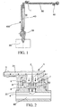
- FIG. 1 is a schematic structural diagram of a coffee maker system.
- a coffee maker 100 has a water tank 20, a water pump 30, a heating apparatus 40, and a brewing chamber 50, and a valve body 1 is provided upstream of the brewing chamber 50.
- FIG. 2 is a schematic sectional view of a valve body.
- FIG. 3 is a schematic exploded diagram of a valve body.
- FIG. 4 is a schematic structural diagram of a cover body of a first type.
- FIG. 5 is a schematic sectional view of a cover body of a first type.
- the valve body 1 includes:
- the first chamber 51 is in communication with external atmosphere, and the air pressure is P0.
- the air pressure of the second chamber 52 is a changing internal air pressure P1 of the coffee maker.
- the cover body 8 elastically deforms under an air pressure difference between P0 and P1 to seal or open the air hole 7, to control air communication between the second chamber 52 and the external atmosphere.
- the cover body 8 seals the air hole 7.
- the cover body 8 elastically deforms (flips) and leaves the separator plate 6, to open the air hole 7. Therefore, the air pressure balance is maintained in the system, the brewing chamber 50 is not affected, and a status such as back suction does not appear.
- the cover body 8 is made of a silica gel material, is easily made and easily generates elastic deformation.
- the cover body 8 is of an umbrella-shaped structure, and using the umbrella-shaped structure can make the cover body has a cavity, so that the cover body easily generates deformation.
- the separator plate 6 has a through hole 10
- a cylinder 81 is provided on the cover body 8, where the cylinder 81 penetrates the through hole 10, and the cover body 8 is mounted on the separator plate 6 by using a clamping portion 811 on the cylinder 81.
- the design helps the cover body be mounted onto the separator plate, facilitating latter cleaning and replacing.
- FIG. 6 is a schematic sectional view of a cover body of a second type. As shown in FIG. 6 , an end 82 of the cover body 8 is connected to a surface 62 that is of the separator plate 6 and that is located in the second chamber 52. When a pressure difference of the system changes, the cover body 8 deforms, for example, approaches the separator plate 6, or leaves the separator plate 6 and flips to open the air hole 7. To further ensure air tightness between the first chamber 51 and the second chamber 52, the valve body 1 further includes a seal ring 9 disposed in the housing 2 and abutting the separator plate 6.
- the housing 2 includes a first housing 21 and a second housing 22, the air hole 7 being provided on the first housing 21, and the opening 4 being provided on the second housing 22.
- the detachable housing facilitates the mounting of internal components of the valve body 1.
- a protrusion 301 and a groove 302 engaging with each other are provided on outer walls 210, and 220 of the first housing 21 and the second housing 22.
- the protrusion engages with the groove by means of clamping, facilitating mounting and assembling.
- the problem in the prior art that the pressure relief is not convenient or is complex to be performed in the coffee maker after a coffee is brewed is resolved, so that the coffee maker automatically balances the internal negative pressure thereof after the brewing is completed, and no manual operation is needed.
- a structure is simple, a cost is low, and use experience of a user is improved at the same time.
Landscapes
- Engineering & Computer Science (AREA)
- General Engineering & Computer Science (AREA)
- Mechanical Engineering (AREA)
- Food Science & Technology (AREA)
- Physics & Mathematics (AREA)
- Fluid Mechanics (AREA)
- Apparatus For Making Beverages (AREA)
Abstract
The present invention discloses a valve body and a coffee maker having the valve body. The valve body includes: a housing internally having a chamber, the housing being provided with an air hole in communication with the outside and an opening in communication with a hot water pipe of the coffee maker; a separator plate separating the chamber into a first chamber and a second chamber, the first chamber being in communication with the air hole, the second chamber being in communication with the opening, and an air hole being provided on the separator plate; and a cover body disposed in the second chamber, where the cover body elastically deforms under the control of an air pressure difference between the first chamber and the second chamber to seal or open the air hole, to control ventilation between the first chamber and the second chamber.
Description
- The present invention relates to the field of home appliance technologies, and specifically to a valve body and a coffee maker having the valve body.
- Most existing beverage preparation machines, such as a coffee maker, have a "brewing chamber" or a "brewing unit" for accommodating ingredients that are divided into parts for preparing food or a beverage. A water pump delivers water from a water tank to a heating apparatus for heating, and the water is heated therein and transported to the brewing chamber. The pump stops delivery of water after preset water consumption is reached, while the heating apparatus further operates. Water still that stays in the heating apparatus is quickly converted to vapor and generates a vapor pressure, because no more water is supplied subsequently to cool down the water in the heating apparatus. The pressure pushes hot water into the brewing chamber, and a corresponding coffee beverage is prepared and then flows into a cup. A pressure and a water temperature greatly affect the coffee taste, and therefore the pressure in the brewing chamber is greater than the atmospheric pressure. For extraction of baked and ground coffee, the required pressure is usually approximately 2 bars to 12 bars.
- After the brewing ends, the heating apparatus stops heating, and when a temperature in the system reduces below a boiling point of water, vapor in a downstream pipe of a heating pipe cools down, so that the vapor condenses in the pipe and a volume thereof reduces, and a negative pressure is generated. If air is taken out or residual liquid is brought out from the brewing chamber by the negative pressure, the pressure balance in the brewing chamber may be affected. To prevent this, a one-way valve is provided upstream of the brewing chamber. For example, the one-way valve may be designed as an elastic grooving diaphragm. However, the function of the one-way valve may be impaired due to aging and a machining tolerance of the diaphragm. Consequently, air tightness cannot be completely ensured.
- For the problem in the prior art that the pressure balance of the brewing chamber is affected because the air tightness of the one-way valve in the coffee maker cannot be ensured, no effective solutions are provided currently.
- The present invention provides a valve body and a coffee maker having the valve body, to resolve at least the problem in the prior art that a pressure balance of a brewing chamber is affected because air tightness of a one-way valve cannot be ensured.
- To achieve the objective, according to an aspect of the present invention, a valve body is provided.
- According to a valve body, of the present invention, for a coffee maker, the valve body includes: a housing internally having a chamber, the housing being provided with an air hole in communication with the outside and an opening in communication with a hot water pipe of the coffee maker; and
a separator plate separating the chamber into a first chamber and a second chamber, the first chamber being in communication with the air hole, the second chamber being in communication with the opening, and an air hole being provided on the separator plate; and a cover body disposed in the second chamber, where the cover body elastically deforms under the control of an air pressure difference between the first chamber and the second chamber to seal or open the air hole, to control air communication between the first chamber and the second chamber. The first chamber is in communication with external atmosphere, the air pressure of the second chamber is a changing internal air pressure, and the cover body elastically deforms under an air pressure difference between the first chamber and the second chamber to seal or open the air hole, to control air communication between the second chamber and the external atmosphere, so that a pressure balance of the system is implemented, and the brewing chamber. - Preferably, the cover body seals the air hole when the air pressure of the first chamber is balanced with that of the second chamber or the air pressure of the second chamber is greater than the air pressure of the first chamber.
- Preferably, when the air pressure of the first chamber is greater than the air pressure of the second chamber, the cover body elastically deforms and leaves the separator plate, to open the air hole.
- Preferably, when the air pressure of the second chamber is greater than the air pressure of the first chamber, the cover body elastically deforms and approaches the separator plate, to seal the air hole.
- Preferably, the separator plate has a through hole, and a cylinder is provided on the cover body, where the cylinder penetrates the through hole, and the cover body is mounted on the separator plate by using a clamping portion on the cylinder. The design helps the cover body be mounted onto the separator plate, facilitating latter cleaning and replacing.
- Preferably, the cover body is made of a silica gel material. Preferably, the cover body is of an umbrella-shaped structure. Preferably, a seal ring disposed in the housing and abutting against the separator plate is provided.
- Preferably, the housing includes a first housing and a second housing, the air hole being provided on the first housing, and the opening being provided on the second housing.
- Preferably, outer walls of the first housing and the second housing are provided with a protrusion and a groove engaging with each other.
- According to the other aspect of the present invention, a coffee maker is provided. The coffee maker has a water tank, a heating pipe and a brewing chamber, and has the valve body described above.
- Based on the present invention, the problem in the prior art that the pressure balance of the brewing chamber is affected because the air tightness of the one-way valve cannot be ensured is resolved, so that the coffee maker automatically balances internal negative pressure thereof after the brewing is completed, and no manual operation is needed. In addition, the present invention has a simple structure and a cost is low, and improves use experience of a user.
- The accompanying drawings herein are used for providing further understanding of the present invention, and constitute a part of this application. Schematic embodiments of the present invention and the illustration thereof are used for describing the present invention, and do not constitute inappropriate limitation on the present invention. In the drawings:
- FIG. 1
- is a schematic structural diagram of a coffee maker system;
- FIG. 2
- is a schematic sectional view of a valve body;
- FIG. 3
- is a schematic exploded diagram of a valve body;
- FIG. 4
- is a schematic structural diagram of a cover body of a first type;
- FIG. 5
- is a schematic sectional view of a cover body of a first type; and
- FIG. 6
- is a schematic sectional view of a cover body of a second type.
- The following descries the present invention in detail with reference to the accompanying drawings and in accordance with embodiments. It should be noted that the embodiments in this application and the features in the embodiments may be mutually combined as long as they do not conflict.
- In an embodiment,
FIG. 1 is a schematic structural diagram of a coffee maker system. As shown inFIG. 1 , acoffee maker 100 has a water tank 20, awater pump 30, aheating apparatus 40, and abrewing chamber 50, and a valve body 1 is provided upstream of thebrewing chamber 50. -
FIG. 2 is a schematic sectional view of a valve body.FIG. 3 is a schematic exploded diagram of a valve body.FIG. 4 is a schematic structural diagram of a cover body of a first type.FIG. 5 is a schematic sectional view of a cover body of a first type. As shown inFIG. 2 ,FIG. 3 ,FIG. 4 andFIG. 5 , the valve body 1 includes: - a
housing 2 internally having a chamber 5; - the
housing 2 being provided with anair hole 3 in communication with the outside and anopening 4 in communication with ahot water pipe 60 of thecoffee maker 100; - a
separator plate 6 separating the chamber 5 into afirst chamber 51 and a second chamber 52, thefirst chamber 51 being in communication with theair hole 3, the second chamber 52 being in communication with theopening 4, and anair hole 7 being provided on theseparator plate 6; - a
cover body 8 disposed in the second chamber 52, - where the
cover body 8 elastically deforms under the control of an air pressure difference between thefirst chamber 51 and the second chamber 52 to seal or open theair hole 7, to control air communication between thefirst chamber 51 and the second chamber 52. - The
first chamber 51 is in communication with external atmosphere, and the air pressure is P0. The air pressure of the second chamber 52 is a changing internal air pressure P1 of the coffee maker. Thecover body 8 elastically deforms under an air pressure difference between P0 and P1 to seal or open theair hole 7, to control air communication between the second chamber 52 and the external atmosphere. - Specifically, when the air pressure of the
first chamber 51 is balanced with that of the second chamber 52, or the air pressure of the second chamber 52 is greater than the air pressure of thefirst chamber 51, thecover body 8 seals theair hole 7. - In a normal state, the air pressure of the
first chamber 51 is balanced with that of the second chamber 52, and thecover body 8 is in a closed state. - In a process of brewing and preparing a coffee by using a coffee maker, as heating is performed, vapor is generated, and the air pressure in the system increases. When the air pressure of the second chamber 52 is greater than the air pressure of the
first chamber 51, thecover body 8 elastically deforms and approaches theseparator plate 6, to seal theair hole 7, so that air tightness is ensured. - After the coffee is brewed by using the coffee maker, the vapor condenses, and the air pressure in the system reduces to a negative pressure. When the air pressure of the
first chamber 51 is greater than the air pressure of the second chamber 52, thecover body 8 elastically deforms (flips) and leaves theseparator plate 6, to open theair hole 7. Therefore, the air pressure balance is maintained in the system, thebrewing chamber 50 is not affected, and a status such as back suction does not appear. - Elastic deformation of the cover body is completely caused by the internal and the external air pressure, no manual operation is needed, a structure is simple, and a cost is low.
- Preferably, the
cover body 8 is made of a silica gel material, is easily made and easily generates elastic deformation. Thecover body 8 is of an umbrella-shaped structure, and using the umbrella-shaped structure can make the cover body has a cavity, so that the cover body easily generates deformation. - Preferably, as shown in
FIG. 4 andFIG. 5 , theseparator plate 6 has a throughhole 10, acylinder 81 is provided on thecover body 8, where thecylinder 81 penetrates the throughhole 10, and thecover body 8 is mounted on theseparator plate 6 by using a clampingportion 811 on thecylinder 81. The design helps the cover body be mounted onto the separator plate, facilitating latter cleaning and replacing. - The
cover body 8 may further adopt another type of manner.FIG. 6 is a schematic sectional view of a cover body of a second type. As shown inFIG. 6 , anend 82 of thecover body 8 is connected to a surface 62 that is of theseparator plate 6 and that is located in the second chamber 52. When a pressure difference of the system changes, thecover body 8 deforms, for example, approaches theseparator plate 6, or leaves theseparator plate 6 and flips to open theair hole 7.
To further ensure air tightness between thefirst chamber 51 and the second chamber 52, the valve body 1 further includes aseal ring 9 disposed in thehousing 2 and abutting theseparator plate 6. - Preferably, the
housing 2 includes afirst housing 21 and asecond housing 22, theair hole 7 being provided on thefirst housing 21, and theopening 4 being provided on thesecond housing 22. The detachable housing facilitates the mounting of internal components of the valve body 1. - A
protrusion 301 and agroove 302 engaging with each other are provided onouter walls first housing 21 and thesecond housing 22. The protrusion engages with the groove by means of clamping, facilitating mounting and assembling. - Based on the present invention, the problem in the prior art that the pressure relief is not convenient or is complex to be performed in the coffee maker after a coffee is brewed is resolved, so that the coffee maker automatically balances the internal negative pressure thereof after the brewing is completed, and no manual operation is needed. In addition, a structure is simple, a cost is low, and use experience of a user is improved at the same time.
- The embodiments described in the foregoing and shown in the accompanying drawings are merely used for illustrating the present invention, and are not the entire present invention. Within the scope of basic technical ideas of the present invention, changes in any form made by a person of ordinary skill in the related art shall all fall within the protection scope of the present invention.
Claims (11)
- A valve body (1) for a coffee maker (100), characterized in that the valve body (1) comprises:a housing (2) internally having a chamber (5), the housing (2) being provided with an air hole (3) in communication with the outside and an opening (4) in communication with a hot water pipe (60) of the coffee maker (100);a separator plate (6) separating the chamber (5) into a first chamber (51) and a second chamber (52), the first chamber (51) being in communication with the air hole (3), the second chamber (52) being in communication with the opening (4), and an air hole (7) being provided on the separator plate (6); anda cover body (8) disposed in the second chamber (52),wherein the cover body (8) elastically deforms under the control of an air pressure difference between the first chamber (51) and the second chamber (52) to seal or open the air hole (7), to control ventilation between the first chamber (51) and the second chamber (52).
- The valve body according to claim 1, characterized in that
the cover body (8) seals the air hole (7) when the air pressure of the first chamber (51) is balanced with that of the second chamber (52) or the air pressure of the second chamber (52) is greater than the air pressure of the first chamber (51). - The valve body according to claim 2, characterized in that
when the air pressure of the first chamber (51) is greater than the air pressure of the second chamber (52), the cover body (8) elastically deforms and leaves the separator plate (6), to open the air hole (7). - The valve body according to claim 2, characterized in that
when the air pressure of the second chamber (52) is greater than the air pressure of the first chamber (51), the cover body (8) elastically deforms and approaches the separator plate (6), to seal the air hole (7). - The valve body according to claim 3, characterized in that
the separator plate (6) has a through hole (10), and a cylinder (81) is provided on the cover body (8),
wherein the cylinder (81) penetrates the through hole (10), and the cover body (8) is mounted on the separator plate (6) by using a clamping portion (811) on the cylinder (81). - The valve body according to claim 1, characterized in that
the cover body (8) is made of a silica gel material. - The valve body according to claim 1, characterized in that
the cover body (8) is of an umbrella-shaped structure. - The valve body according to claim 1, characterized by comprising:a seal ring (9) disposed in the housing (2) and abutting against the separator plate (6).
- The valve body according to claim 1, characterized in that
the housing (2) comprises a first housing (21) and a second housing (22), the air hole (3) being provided on the first housing (21), and the opening (4) being provided on the second housing (22). - The valve body according to claim 1, characterized in that
a protrusion (301) and a groove (302) engaging with each other are provided on outer walls (210, 220) of the first housing (21) and the second housing (22). - A coffee maker (100), comprising a water tank (20), a heating pipe (40) and a brewing chamber (50), and characterized by comprising:the valve body according to any one of claims 1 to 10.
Applications Claiming Priority (1)
| Application Number | Priority Date | Filing Date | Title |
|---|---|---|---|
| CN201710748071.3A CN109419364A (en) | 2017-08-28 | 2017-08-28 | Valve body and coffee machine with the valve body |
Publications (1)
| Publication Number | Publication Date |
|---|---|
| EP3449782A1 true EP3449782A1 (en) | 2019-03-06 |
Family
ID=63878312
Family Applications (1)
| Application Number | Title | Priority Date | Filing Date |
|---|---|---|---|
| EP18191184.3A Withdrawn EP3449782A1 (en) | 2017-08-28 | 2018-08-28 | Valve body and coffee maker having same |
Country Status (2)
| Country | Link |
|---|---|
| EP (1) | EP3449782A1 (en) |
| CN (1) | CN109419364A (en) |
Cited By (3)
| Publication number | Priority date | Publication date | Assignee | Title |
|---|---|---|---|---|
| CN110081602A (en) * | 2019-04-27 | 2019-08-02 | 广东亿龙电器科技有限公司 | One kind letting out residual aqueous vapor device |
| EP4019816A1 (en) * | 2020-12-14 | 2022-06-29 | B/E Aerospace, Inc. | Venting devices for aircraft brewing apparatus |
| CN116869355A (en) * | 2023-05-10 | 2023-10-13 | 安徽雷格斯科技有限公司 | A graphene electric kettle |
Families Citing this family (3)
| Publication number | Priority date | Publication date | Assignee | Title |
|---|---|---|---|---|
| JP7376935B2 (en) * | 2019-01-31 | 2023-11-09 | 株式会社フジキン | Flow path assembly, valve device using this flow path assembly, fluid control device, semiconductor manufacturing device, and semiconductor manufacturing method |
| CN110123144A (en) * | 2019-05-07 | 2019-08-16 | 宁波心想科技有限公司 | Back pressure valve arrangement and beverage extraction plant with the back pressure valve arrangement |
| CN111820745A (en) * | 2019-08-06 | 2020-10-27 | 宁波白蚁网络科技有限公司 | Universal scavenging cover |
Citations (7)
| Publication number | Priority date | Publication date | Assignee | Title |
|---|---|---|---|---|
| EP0117785A2 (en) * | 1983-01-31 | 1984-09-05 | AlliedSignal Inc. | Vacuum check valve |
| WO2002100227A1 (en) * | 2001-06-08 | 2002-12-19 | Sara Lee/De N.V. | Apparatus for preparing a beverage suitable for consumption, such as coffee |
| US20080041231A1 (en) * | 2006-08-17 | 2008-02-21 | The Procter & Gamble Company | Method and device for brewing beverages |
| WO2010043952A1 (en) * | 2008-10-14 | 2010-04-22 | Sgl Italia S.R.L. Con Unico Socio | Infusion unit |
| DE102011084839A1 (en) * | 2011-10-20 | 2013-04-25 | BSH Bosch und Siemens Hausgeräte GmbH | Valve assembly for hot beverage preparation device for household use, has pressure equalizing device that switches over or under pressure, where pressure equalizing device is installed in fluid line of cooking apparatus |
| US20130239817A1 (en) * | 2012-03-14 | 2013-09-19 | Hamilton Beach Brands, Inc. | Kitchen Appliance for Preparing a Beverage and Method of Operating Same |
| CN106855143A (en) * | 2015-12-08 | 2017-06-16 | 北京谊安医疗系统股份有限公司 | A kind of diaphragm check valve |
Family Cites Families (4)
| Publication number | Priority date | Publication date | Assignee | Title |
|---|---|---|---|---|
| IT233538Y1 (en) * | 1994-07-01 | 2000-01-28 | Miralfin Srl | VALVE DEVICE FOR THE SELF-PRIMING OF A PUMP PARTICULARLY FOR MACHINES FOR THE PRODUCTION OF AN INFUSION OF COFFEE |
| CN103479228B (en) * | 2013-09-18 | 2015-10-28 | 宁波全景电器技术有限公司 | Anti negative pressure spout |
| CN106321883B (en) * | 2015-06-24 | 2019-03-12 | 广东美的生活电器制造有限公司 | Valve body and coffee machine having the same |
| CN204784838U (en) * | 2015-06-24 | 2015-11-18 | 广东美的生活电器制造有限公司 | Valve body and have coffee machine of this valve body |
-
2017
- 2017-08-28 CN CN201710748071.3A patent/CN109419364A/en active Pending
-
2018
- 2018-08-28 EP EP18191184.3A patent/EP3449782A1/en not_active Withdrawn
Patent Citations (7)
| Publication number | Priority date | Publication date | Assignee | Title |
|---|---|---|---|---|
| EP0117785A2 (en) * | 1983-01-31 | 1984-09-05 | AlliedSignal Inc. | Vacuum check valve |
| WO2002100227A1 (en) * | 2001-06-08 | 2002-12-19 | Sara Lee/De N.V. | Apparatus for preparing a beverage suitable for consumption, such as coffee |
| US20080041231A1 (en) * | 2006-08-17 | 2008-02-21 | The Procter & Gamble Company | Method and device for brewing beverages |
| WO2010043952A1 (en) * | 2008-10-14 | 2010-04-22 | Sgl Italia S.R.L. Con Unico Socio | Infusion unit |
| DE102011084839A1 (en) * | 2011-10-20 | 2013-04-25 | BSH Bosch und Siemens Hausgeräte GmbH | Valve assembly for hot beverage preparation device for household use, has pressure equalizing device that switches over or under pressure, where pressure equalizing device is installed in fluid line of cooking apparatus |
| US20130239817A1 (en) * | 2012-03-14 | 2013-09-19 | Hamilton Beach Brands, Inc. | Kitchen Appliance for Preparing a Beverage and Method of Operating Same |
| CN106855143A (en) * | 2015-12-08 | 2017-06-16 | 北京谊安医疗系统股份有限公司 | A kind of diaphragm check valve |
Cited By (3)
| Publication number | Priority date | Publication date | Assignee | Title |
|---|---|---|---|---|
| CN110081602A (en) * | 2019-04-27 | 2019-08-02 | 广东亿龙电器科技有限公司 | One kind letting out residual aqueous vapor device |
| EP4019816A1 (en) * | 2020-12-14 | 2022-06-29 | B/E Aerospace, Inc. | Venting devices for aircraft brewing apparatus |
| CN116869355A (en) * | 2023-05-10 | 2023-10-13 | 安徽雷格斯科技有限公司 | A graphene electric kettle |
Also Published As
| Publication number | Publication date |
|---|---|
| CN109419364A (en) | 2019-03-05 |
Similar Documents
| Publication | Publication Date | Title |
|---|---|---|
| CN109419364A (en) | Valve body and coffee machine with the valve body | |
| US4565121A (en) | Apparatus for use in preparing infusions | |
| EP3078308B1 (en) | Coffee extraction device | |
| US12295522B2 (en) | Mixing apparatus having a seal | |
| JPS5941772Y2 (en) | Coffee boiler for families and small cafes | |
| CN208425952U (en) | Waterway Components and Drinking Fixtures | |
| EP3731704B1 (en) | A mixing apparatus having a seal | |
| CN104970695B (en) | Fully automatic cooking and steaming integrated rice cooker | |
| CN103371723B (en) | Funnel structure of two-in-one coffee machine | |
| CN202168742U (en) | Structure of general capsule coffee maker | |
| CN201752351U (en) | Water storage type coffee machine | |
| US20080173182A1 (en) | Machine for the preparation of a hot drink | |
| CN210697198U (en) | Pressure relief device of electric pressure cooker | |
| CN111387817A (en) | Heating device and using method thereof | |
| CN209826258U (en) | Novel rice steaming heat preservation electric cooker | |
| CN206333748U (en) | Brewing machine | |
| CN110623518B (en) | Stewing and steaming device | |
| CN216256670U (en) | Cup cover and electric heating cup | |
| CN221949658U (en) | A tea machine | |
| CN221469665U (en) | Container cover assembly and cooking utensil | |
| CN213155343U (en) | Lid assembly for a cooking appliance and cooking appliance | |
| CN213248363U (en) | Cooking utensil | |
| TWI726769B (en) | Coffee flushing method and device | |
| CN205162770U (en) | Coffee pot | |
| CN214595492U (en) | Lid assembly and have its cooking utensil |
Legal Events
| Date | Code | Title | Description |
|---|---|---|---|
| PUAI | Public reference made under article 153(3) epc to a published international application that has entered the european phase |
Free format text: ORIGINAL CODE: 0009012 |
|
| AK | Designated contracting states |
Kind code of ref document: A1 Designated state(s): AL AT BE BG CH CY CZ DE DK EE ES FI FR GB GR HR HU IE IS IT LI LT LU LV MC MK MT NL NO PL PT RO RS SE SI SK SM TR |
|
| AX | Request for extension of the european patent |
Extension state: BA ME |
|
| STAA | Information on the status of an ep patent application or granted ep patent |
Free format text: STATUS: THE APPLICATION IS DEEMED TO BE WITHDRAWN |
|
| 18D | Application deemed to be withdrawn |
Effective date: 20190907 |