EP3449175B1 - An arrangement for a liquefied gas fuel system for a vehicle - Google Patents
An arrangement for a liquefied gas fuel system for a vehicle Download PDFInfo
- Publication number
- EP3449175B1 EP3449175B1 EP17790015.6A EP17790015A EP3449175B1 EP 3449175 B1 EP3449175 B1 EP 3449175B1 EP 17790015 A EP17790015 A EP 17790015A EP 3449175 B1 EP3449175 B1 EP 3449175B1
- Authority
- EP
- European Patent Office
- Prior art keywords
- vehicle
- arrangement
- liquefied gas
- gas fuel
- tank
- Prior art date
- Legal status (The legal status is an assumption and is not a legal conclusion. Google has not performed a legal analysis and makes no representation as to the accuracy of the status listed.)
- Active
Links
Images


Classifications
-
- F—MECHANICAL ENGINEERING; LIGHTING; HEATING; WEAPONS; BLASTING
- F17—STORING OR DISTRIBUTING GASES OR LIQUIDS
- F17C—VESSELS FOR CONTAINING OR STORING COMPRESSED, LIQUEFIED OR SOLIDIFIED GASES; FIXED-CAPACITY GAS-HOLDERS; FILLING VESSELS WITH, OR DISCHARGING FROM VESSELS, COMPRESSED, LIQUEFIED, OR SOLIDIFIED GASES
- F17C13/00—Details of vessels or of the filling or discharging of vessels
- F17C13/08—Mounting arrangements for vessels
- F17C13/083—Mounting arrangements for vessels for medium-sized mobile storage vessels, e.g. tank vehicles or railway tank vehicles
-
- B—PERFORMING OPERATIONS; TRANSPORTING
- B60—VEHICLES IN GENERAL
- B60K—ARRANGEMENT OR MOUNTING OF PROPULSION UNITS OR OF TRANSMISSIONS IN VEHICLES; ARRANGEMENT OR MOUNTING OF PLURAL DIVERSE PRIME-MOVERS IN VEHICLES; AUXILIARY DRIVES FOR VEHICLES; INSTRUMENTATION OR DASHBOARDS FOR VEHICLES; ARRANGEMENTS IN CONNECTION WITH COOLING, AIR INTAKE, GAS EXHAUST OR FUEL SUPPLY OF PROPULSION UNITS IN VEHICLES
- B60K15/00—Arrangement in connection with fuel supply of combustion engines or other fuel consuming energy converters, e.g. fuel cells; Mounting or construction of fuel tanks
- B60K15/01—Arrangement of fuel conduits
- B60K15/013—Arrangement of fuel conduits of gas conduits
-
- B—PERFORMING OPERATIONS; TRANSPORTING
- B60—VEHICLES IN GENERAL
- B60K—ARRANGEMENT OR MOUNTING OF PROPULSION UNITS OR OF TRANSMISSIONS IN VEHICLES; ARRANGEMENT OR MOUNTING OF PLURAL DIVERSE PRIME-MOVERS IN VEHICLES; AUXILIARY DRIVES FOR VEHICLES; INSTRUMENTATION OR DASHBOARDS FOR VEHICLES; ARRANGEMENTS IN CONNECTION WITH COOLING, AIR INTAKE, GAS EXHAUST OR FUEL SUPPLY OF PROPULSION UNITS IN VEHICLES
- B60K15/00—Arrangement in connection with fuel supply of combustion engines or other fuel consuming energy converters, e.g. fuel cells; Mounting or construction of fuel tanks
- B60K15/03—Fuel tanks
- B60K15/063—Arrangement of tanks
- B60K15/067—Mounting of tanks
- B60K15/07—Mounting of tanks of gas tanks
-
- B—PERFORMING OPERATIONS; TRANSPORTING
- B60—VEHICLES IN GENERAL
- B60K—ARRANGEMENT OR MOUNTING OF PROPULSION UNITS OR OF TRANSMISSIONS IN VEHICLES; ARRANGEMENT OR MOUNTING OF PLURAL DIVERSE PRIME-MOVERS IN VEHICLES; AUXILIARY DRIVES FOR VEHICLES; INSTRUMENTATION OR DASHBOARDS FOR VEHICLES; ARRANGEMENTS IN CONNECTION WITH COOLING, AIR INTAKE, GAS EXHAUST OR FUEL SUPPLY OF PROPULSION UNITS IN VEHICLES
- B60K15/00—Arrangement in connection with fuel supply of combustion engines or other fuel consuming energy converters, e.g. fuel cells; Mounting or construction of fuel tanks
- B60K15/03—Fuel tanks
- B60K15/03006—Gas tanks
-
- B—PERFORMING OPERATIONS; TRANSPORTING
- B60—VEHICLES IN GENERAL
- B60K—ARRANGEMENT OR MOUNTING OF PROPULSION UNITS OR OF TRANSMISSIONS IN VEHICLES; ARRANGEMENT OR MOUNTING OF PLURAL DIVERSE PRIME-MOVERS IN VEHICLES; AUXILIARY DRIVES FOR VEHICLES; INSTRUMENTATION OR DASHBOARDS FOR VEHICLES; ARRANGEMENTS IN CONNECTION WITH COOLING, AIR INTAKE, GAS EXHAUST OR FUEL SUPPLY OF PROPULSION UNITS IN VEHICLES
- B60K15/00—Arrangement in connection with fuel supply of combustion engines or other fuel consuming energy converters, e.g. fuel cells; Mounting or construction of fuel tanks
- B60K15/03—Fuel tanks
- B60K15/063—Arrangement of tanks
-
- F—MECHANICAL ENGINEERING; LIGHTING; HEATING; WEAPONS; BLASTING
- F02—COMBUSTION ENGINES; HOT-GAS OR COMBUSTION-PRODUCT ENGINE PLANTS
- F02M—SUPPLYING COMBUSTION ENGINES IN GENERAL WITH COMBUSTIBLE MIXTURES OR CONSTITUENTS THEREOF
- F02M21/00—Apparatus for supplying engines with non-liquid fuels, e.g. gaseous fuels stored in liquid form
- F02M21/02—Apparatus for supplying engines with non-liquid fuels, e.g. gaseous fuels stored in liquid form for gaseous fuels
- F02M21/0203—Apparatus for supplying engines with non-liquid fuels, e.g. gaseous fuels stored in liquid form for gaseous fuels characterised by the type of gaseous fuel
- F02M21/0209—Hydrocarbon fuels, e.g. methane or acetylene
-
- F—MECHANICAL ENGINEERING; LIGHTING; HEATING; WEAPONS; BLASTING
- F02—COMBUSTION ENGINES; HOT-GAS OR COMBUSTION-PRODUCT ENGINE PLANTS
- F02M—SUPPLYING COMBUSTION ENGINES IN GENERAL WITH COMBUSTIBLE MIXTURES OR CONSTITUENTS THEREOF
- F02M21/00—Apparatus for supplying engines with non-liquid fuels, e.g. gaseous fuels stored in liquid form
- F02M21/02—Apparatus for supplying engines with non-liquid fuels, e.g. gaseous fuels stored in liquid form for gaseous fuels
- F02M21/0203—Apparatus for supplying engines with non-liquid fuels, e.g. gaseous fuels stored in liquid form for gaseous fuels characterised by the type of gaseous fuel
- F02M21/0209—Hydrocarbon fuels, e.g. methane or acetylene
- F02M21/0212—Hydrocarbon fuels, e.g. methane or acetylene comprising at least 3 C-Atoms, e.g. liquefied petroleum gas [LPG], propane or butane
-
- F—MECHANICAL ENGINEERING; LIGHTING; HEATING; WEAPONS; BLASTING
- F02—COMBUSTION ENGINES; HOT-GAS OR COMBUSTION-PRODUCT ENGINE PLANTS
- F02M—SUPPLYING COMBUSTION ENGINES IN GENERAL WITH COMBUSTIBLE MIXTURES OR CONSTITUENTS THEREOF
- F02M21/00—Apparatus for supplying engines with non-liquid fuels, e.g. gaseous fuels stored in liquid form
- F02M21/02—Apparatus for supplying engines with non-liquid fuels, e.g. gaseous fuels stored in liquid form for gaseous fuels
- F02M21/0218—Details on the gaseous fuel supply system, e.g. tanks, valves, pipes, pumps, rails, injectors or mixers
-
- F—MECHANICAL ENGINEERING; LIGHTING; HEATING; WEAPONS; BLASTING
- F02—COMBUSTION ENGINES; HOT-GAS OR COMBUSTION-PRODUCT ENGINE PLANTS
- F02M—SUPPLYING COMBUSTION ENGINES IN GENERAL WITH COMBUSTIBLE MIXTURES OR CONSTITUENTS THEREOF
- F02M21/00—Apparatus for supplying engines with non-liquid fuels, e.g. gaseous fuels stored in liquid form
- F02M21/02—Apparatus for supplying engines with non-liquid fuels, e.g. gaseous fuels stored in liquid form for gaseous fuels
- F02M21/0218—Details on the gaseous fuel supply system, e.g. tanks, valves, pipes, pumps, rails, injectors or mixers
- F02M21/0221—Fuel storage reservoirs, e.g. cryogenic tanks
-
- F—MECHANICAL ENGINEERING; LIGHTING; HEATING; WEAPONS; BLASTING
- F17—STORING OR DISTRIBUTING GASES OR LIQUIDS
- F17C—VESSELS FOR CONTAINING OR STORING COMPRESSED, LIQUEFIED OR SOLIDIFIED GASES; FIXED-CAPACITY GAS-HOLDERS; FILLING VESSELS WITH, OR DISCHARGING FROM VESSELS, COMPRESSED, LIQUEFIED, OR SOLIDIFIED GASES
- F17C1/00—Pressure vessels, e.g. gas cylinder, gas tank, replaceable cartridge
-
- F—MECHANICAL ENGINEERING; LIGHTING; HEATING; WEAPONS; BLASTING
- F17—STORING OR DISTRIBUTING GASES OR LIQUIDS
- F17C—VESSELS FOR CONTAINING OR STORING COMPRESSED, LIQUEFIED OR SOLIDIFIED GASES; FIXED-CAPACITY GAS-HOLDERS; FILLING VESSELS WITH, OR DISCHARGING FROM VESSELS, COMPRESSED, LIQUEFIED, OR SOLIDIFIED GASES
- F17C13/00—Details of vessels or of the filling or discharging of vessels
- F17C13/08—Mounting arrangements for vessels
-
- F—MECHANICAL ENGINEERING; LIGHTING; HEATING; WEAPONS; BLASTING
- F17—STORING OR DISTRIBUTING GASES OR LIQUIDS
- F17C—VESSELS FOR CONTAINING OR STORING COMPRESSED, LIQUEFIED OR SOLIDIFIED GASES; FIXED-CAPACITY GAS-HOLDERS; FILLING VESSELS WITH, OR DISCHARGING FROM VESSELS, COMPRESSED, LIQUEFIED, OR SOLIDIFIED GASES
- F17C13/00—Details of vessels or of the filling or discharging of vessels
- F17C13/12—Arrangements or mounting of devices for preventing or minimising the effect of explosion ; Other safety measures
- F17C13/123—Arrangements or mounting of devices for preventing or minimising the effect of explosion ; Other safety measures for gas bottles, cylinders or reservoirs for tank vehicles or for railway tank wagons
-
- B—PERFORMING OPERATIONS; TRANSPORTING
- B60—VEHICLES IN GENERAL
- B60K—ARRANGEMENT OR MOUNTING OF PROPULSION UNITS OR OF TRANSMISSIONS IN VEHICLES; ARRANGEMENT OR MOUNTING OF PLURAL DIVERSE PRIME-MOVERS IN VEHICLES; AUXILIARY DRIVES FOR VEHICLES; INSTRUMENTATION OR DASHBOARDS FOR VEHICLES; ARRANGEMENTS IN CONNECTION WITH COOLING, AIR INTAKE, GAS EXHAUST OR FUEL SUPPLY OF PROPULSION UNITS IN VEHICLES
- B60K15/00—Arrangement in connection with fuel supply of combustion engines or other fuel consuming energy converters, e.g. fuel cells; Mounting or construction of fuel tanks
- B60K15/03—Fuel tanks
- B60K2015/03309—Tanks specially adapted for particular fuels
-
- B—PERFORMING OPERATIONS; TRANSPORTING
- B60—VEHICLES IN GENERAL
- B60K—ARRANGEMENT OR MOUNTING OF PROPULSION UNITS OR OF TRANSMISSIONS IN VEHICLES; ARRANGEMENT OR MOUNTING OF PLURAL DIVERSE PRIME-MOVERS IN VEHICLES; AUXILIARY DRIVES FOR VEHICLES; INSTRUMENTATION OR DASHBOARDS FOR VEHICLES; ARRANGEMENTS IN CONNECTION WITH COOLING, AIR INTAKE, GAS EXHAUST OR FUEL SUPPLY OF PROPULSION UNITS IN VEHICLES
- B60K15/00—Arrangement in connection with fuel supply of combustion engines or other fuel consuming energy converters, e.g. fuel cells; Mounting or construction of fuel tanks
- B60K15/03—Fuel tanks
- B60K15/063—Arrangement of tanks
- B60K2015/0636—Arrangement of tanks the fuel tank being part of the chassis or frame
-
- B—PERFORMING OPERATIONS; TRANSPORTING
- B60—VEHICLES IN GENERAL
- B60Y—INDEXING SCHEME RELATING TO ASPECTS CROSS-CUTTING VEHICLE TECHNOLOGY
- B60Y2200/00—Type of vehicle
- B60Y2200/10—Road Vehicles
- B60Y2200/14—Trucks; Load vehicles, Busses
- B60Y2200/141—Light trucks
-
- B—PERFORMING OPERATIONS; TRANSPORTING
- B60—VEHICLES IN GENERAL
- B60Y—INDEXING SCHEME RELATING TO ASPECTS CROSS-CUTTING VEHICLE TECHNOLOGY
- B60Y2200/00—Type of vehicle
- B60Y2200/10—Road Vehicles
- B60Y2200/14—Trucks; Load vehicles, Busses
- B60Y2200/142—Heavy duty trucks
-
- B—PERFORMING OPERATIONS; TRANSPORTING
- B60—VEHICLES IN GENERAL
- B60Y—INDEXING SCHEME RELATING TO ASPECTS CROSS-CUTTING VEHICLE TECHNOLOGY
- B60Y2200/00—Type of vehicle
- B60Y2200/10—Road Vehicles
- B60Y2200/14—Trucks; Load vehicles, Busses
- B60Y2200/142—Heavy duty trucks
- B60Y2200/1422—Multi-axle trucks
-
- F—MECHANICAL ENGINEERING; LIGHTING; HEATING; WEAPONS; BLASTING
- F17—STORING OR DISTRIBUTING GASES OR LIQUIDS
- F17C—VESSELS FOR CONTAINING OR STORING COMPRESSED, LIQUEFIED OR SOLIDIFIED GASES; FIXED-CAPACITY GAS-HOLDERS; FILLING VESSELS WITH, OR DISCHARGING FROM VESSELS, COMPRESSED, LIQUEFIED, OR SOLIDIFIED GASES
- F17C2201/00—Vessel construction, in particular geometry, arrangement or size
- F17C2201/05—Size
- F17C2201/056—Small (<1 m3)
-
- F—MECHANICAL ENGINEERING; LIGHTING; HEATING; WEAPONS; BLASTING
- F17—STORING OR DISTRIBUTING GASES OR LIQUIDS
- F17C—VESSELS FOR CONTAINING OR STORING COMPRESSED, LIQUEFIED OR SOLIDIFIED GASES; FIXED-CAPACITY GAS-HOLDERS; FILLING VESSELS WITH, OR DISCHARGING FROM VESSELS, COMPRESSED, LIQUEFIED, OR SOLIDIFIED GASES
- F17C2205/00—Vessel construction, in particular mounting arrangements, attachments or identifications means
- F17C2205/01—Mounting arrangements
- F17C2205/0123—Mounting arrangements characterised by number of vessels
- F17C2205/013—Two or more vessels
-
- F—MECHANICAL ENGINEERING; LIGHTING; HEATING; WEAPONS; BLASTING
- F17—STORING OR DISTRIBUTING GASES OR LIQUIDS
- F17C—VESSELS FOR CONTAINING OR STORING COMPRESSED, LIQUEFIED OR SOLIDIFIED GASES; FIXED-CAPACITY GAS-HOLDERS; FILLING VESSELS WITH, OR DISCHARGING FROM VESSELS, COMPRESSED, LIQUEFIED, OR SOLIDIFIED GASES
- F17C2205/00—Vessel construction, in particular mounting arrangements, attachments or identifications means
- F17C2205/03—Fluid connections, filters, valves, closure means or other attachments
- F17C2205/0302—Fittings, valves, filters, or components in connection with the gas storage device
-
- F—MECHANICAL ENGINEERING; LIGHTING; HEATING; WEAPONS; BLASTING
- F17—STORING OR DISTRIBUTING GASES OR LIQUIDS
- F17C—VESSELS FOR CONTAINING OR STORING COMPRESSED, LIQUEFIED OR SOLIDIFIED GASES; FIXED-CAPACITY GAS-HOLDERS; FILLING VESSELS WITH, OR DISCHARGING FROM VESSELS, COMPRESSED, LIQUEFIED, OR SOLIDIFIED GASES
- F17C2205/00—Vessel construction, in particular mounting arrangements, attachments or identifications means
- F17C2205/03—Fluid connections, filters, valves, closure means or other attachments
- F17C2205/0302—Fittings, valves, filters, or components in connection with the gas storage device
- F17C2205/0352—Pipes
-
- F—MECHANICAL ENGINEERING; LIGHTING; HEATING; WEAPONS; BLASTING
- F17—STORING OR DISTRIBUTING GASES OR LIQUIDS
- F17C—VESSELS FOR CONTAINING OR STORING COMPRESSED, LIQUEFIED OR SOLIDIFIED GASES; FIXED-CAPACITY GAS-HOLDERS; FILLING VESSELS WITH, OR DISCHARGING FROM VESSELS, COMPRESSED, LIQUEFIED, OR SOLIDIFIED GASES
- F17C2205/00—Vessel construction, in particular mounting arrangements, attachments or identifications means
- F17C2205/03—Fluid connections, filters, valves, closure means or other attachments
- F17C2205/0302—Fittings, valves, filters, or components in connection with the gas storage device
- F17C2205/0352—Pipes
- F17C2205/0364—Pipes flexible or articulated, e.g. a hose
-
- F—MECHANICAL ENGINEERING; LIGHTING; HEATING; WEAPONS; BLASTING
- F17—STORING OR DISTRIBUTING GASES OR LIQUIDS
- F17C—VESSELS FOR CONTAINING OR STORING COMPRESSED, LIQUEFIED OR SOLIDIFIED GASES; FIXED-CAPACITY GAS-HOLDERS; FILLING VESSELS WITH, OR DISCHARGING FROM VESSELS, COMPRESSED, LIQUEFIED, OR SOLIDIFIED GASES
- F17C2221/00—Handled fluid, in particular type of fluid
- F17C2221/03—Mixtures
- F17C2221/032—Hydrocarbons
- F17C2221/033—Methane, e.g. natural gas, CNG, LNG, GNL, GNC, PLNG
-
- F—MECHANICAL ENGINEERING; LIGHTING; HEATING; WEAPONS; BLASTING
- F17—STORING OR DISTRIBUTING GASES OR LIQUIDS
- F17C—VESSELS FOR CONTAINING OR STORING COMPRESSED, LIQUEFIED OR SOLIDIFIED GASES; FIXED-CAPACITY GAS-HOLDERS; FILLING VESSELS WITH, OR DISCHARGING FROM VESSELS, COMPRESSED, LIQUEFIED, OR SOLIDIFIED GASES
- F17C2223/00—Handled fluid before transfer, i.e. state of fluid when stored in the vessel or before transfer from the vessel
- F17C2223/01—Handled fluid before transfer, i.e. state of fluid when stored in the vessel or before transfer from the vessel characterised by the phase
- F17C2223/0107—Single phase
- F17C2223/013—Single phase liquid
-
- F—MECHANICAL ENGINEERING; LIGHTING; HEATING; WEAPONS; BLASTING
- F17—STORING OR DISTRIBUTING GASES OR LIQUIDS
- F17C—VESSELS FOR CONTAINING OR STORING COMPRESSED, LIQUEFIED OR SOLIDIFIED GASES; FIXED-CAPACITY GAS-HOLDERS; FILLING VESSELS WITH, OR DISCHARGING FROM VESSELS, COMPRESSED, LIQUEFIED, OR SOLIDIFIED GASES
- F17C2223/00—Handled fluid before transfer, i.e. state of fluid when stored in the vessel or before transfer from the vessel
- F17C2223/01—Handled fluid before transfer, i.e. state of fluid when stored in the vessel or before transfer from the vessel characterised by the phase
- F17C2223/0146—Two-phase
- F17C2223/0153—Liquefied gas, e.g. LPG, GPL
- F17C2223/0161—Liquefied gas, e.g. LPG, GPL cryogenic, e.g. LNG, GNL, PLNG
-
- F—MECHANICAL ENGINEERING; LIGHTING; HEATING; WEAPONS; BLASTING
- F17—STORING OR DISTRIBUTING GASES OR LIQUIDS
- F17C—VESSELS FOR CONTAINING OR STORING COMPRESSED, LIQUEFIED OR SOLIDIFIED GASES; FIXED-CAPACITY GAS-HOLDERS; FILLING VESSELS WITH, OR DISCHARGING FROM VESSELS, COMPRESSED, LIQUEFIED, OR SOLIDIFIED GASES
- F17C2223/00—Handled fluid before transfer, i.e. state of fluid when stored in the vessel or before transfer from the vessel
- F17C2223/03—Handled fluid before transfer, i.e. state of fluid when stored in the vessel or before transfer from the vessel characterised by the pressure level
- F17C2223/033—Small pressure, e.g. for liquefied gas
-
- F—MECHANICAL ENGINEERING; LIGHTING; HEATING; WEAPONS; BLASTING
- F17—STORING OR DISTRIBUTING GASES OR LIQUIDS
- F17C—VESSELS FOR CONTAINING OR STORING COMPRESSED, LIQUEFIED OR SOLIDIFIED GASES; FIXED-CAPACITY GAS-HOLDERS; FILLING VESSELS WITH, OR DISCHARGING FROM VESSELS, COMPRESSED, LIQUEFIED, OR SOLIDIFIED GASES
- F17C2260/00—Purposes of gas storage and gas handling
- F17C2260/01—Improving mechanical properties or manufacturing
- F17C2260/013—Reducing manufacturing time or effort
-
- F—MECHANICAL ENGINEERING; LIGHTING; HEATING; WEAPONS; BLASTING
- F17—STORING OR DISTRIBUTING GASES OR LIQUIDS
- F17C—VESSELS FOR CONTAINING OR STORING COMPRESSED, LIQUEFIED OR SOLIDIFIED GASES; FIXED-CAPACITY GAS-HOLDERS; FILLING VESSELS WITH, OR DISCHARGING FROM VESSELS, COMPRESSED, LIQUEFIED, OR SOLIDIFIED GASES
- F17C2270/00—Applications
- F17C2270/01—Applications for fluid transport or storage
- F17C2270/0165—Applications for fluid transport or storage on the road
- F17C2270/0168—Applications for fluid transport or storage on the road by vehicles
- F17C2270/0171—Trucks
-
- Y—GENERAL TAGGING OF NEW TECHNOLOGICAL DEVELOPMENTS; GENERAL TAGGING OF CROSS-SECTIONAL TECHNOLOGIES SPANNING OVER SEVERAL SECTIONS OF THE IPC; TECHNICAL SUBJECTS COVERED BY FORMER USPC CROSS-REFERENCE ART COLLECTIONS [XRACs] AND DIGESTS
- Y02—TECHNOLOGIES OR APPLICATIONS FOR MITIGATION OR ADAPTATION AGAINST CLIMATE CHANGE
- Y02T—CLIMATE CHANGE MITIGATION TECHNOLOGIES RELATED TO TRANSPORTATION
- Y02T10/00—Road transport of goods or passengers
- Y02T10/10—Internal combustion engine [ICE] based vehicles
- Y02T10/30—Use of alternative fuels, e.g. biofuels
Definitions
- the invention relates to an arrangement for a liquefied gas fuel system for a vehicle.
- the invention also relates to a vehicle.
- liquefied gas fuel tanks of a certain volume are required. For this purpose it is common to provide dual liquefied gas tanks, one at each side of the vehicle frame.
- Liquefied natural gas, LNG, used as fuel for gas trucks is currently transported in rigid pipes from the fuel tank to the engine and venting system.
- the pipes are long and difficult to mount, especially if the trucks have dual tanks. Further, tensions are often built into such liquefied natural gas systems.
- Document US2014/150884A1 discloses a liquid gas system for vehicles, the system comprises two gas reservoirs, connected via feed lines to a changeover switch concurrently integrating a pressure regulator.
- the changeover switch works as follows: when two full gas reservoirs are connected, the changeover switch is adjusted so that gas is withdrawn from the preselected gas reservoir. When this gas reservoir runs empty, the changeover switch automatically switches over to the second full gas reservoir.
- Document US2014/137953A1 discloses a compressed natural gas fuel system comprising a frame, a first container, a second container, a first manifold, a second manifold, and a casing.
- the first manifold may be engaged to and substantially shrouded by the first side of the frame.
- the second manifold may be engaged to and substantially shrouded by the second side of the frame.
- an object of the invention is achieved by an arrangement for a liquefied gas fuel system for a vehicle according to claim 1.
- Said fuel system has two separate liquefied gas fuel tanks for providing fuel to the engine of the vehicle. Said installation of the piping and an easier handling at maintenance. Another advantage is that fewer bendings will allow a less limited flow in the liquefied gas fuel system.
- the respective interface elements are arranged to support said set of pipes.
- the risk of built in tensions in the system is further reduced.
- connection arrangement comprises a support element for said set of pipes arranged between said interface elements.
- one interface element is arranged to be connected to one longitudinal side of the vehicle frame and the other interface element is arranged to be connected to the opposite longitudinal side of the vehicle frame.
- said support element is arranged to be connected to a crossbeam of the vehicle frame.
- said liquefied gas fuel is liquefied natural gas, LNG, or liquefied biogas, LBG.
- a vehicle comprising an arrangement as set out herein.
- liquefied gas refers to liquefied natural gas, LNG, or liquefied biogas, LBG.
- liquefied gas fuel system refers to a fuel system for liquefied natural gas, LNG, or a fuel system for liquefied biogas, LBG.
- hoses refers to hoses configured to transport fluids for a liquefied gas fuel system being bendable to a certain degree and having a certain flexibility so as to facilitate connection to fuel tanks.
- the hoses are according to an embodiment made of Polytetrafluoroethylene (PTFE) or internally lined with a layer of PTFE in order to benefit from the methane resistant properties of PTFE.
- PTFE Polytetrafluoroethylene
- pipes refers to rigid pipes configured to transport fluids for a liquefied gas fuel system which do not provide any flexibility or bendability in comparison to said flexible hoses.
- the pipes are according to an embodiment made of stainless steel.
- the pipes may also be made of copper.
- Fig. 1 schematically illustrates a side view of a vehicle 1 according to the present invention.
- the exemplified vehicle 1 is a heavy vehicle in the shape of a truck.
- the vehicle according to the present invention could be any suitable vehicle.
- the vehicle comprises an arrangement for a liquefied gas fuel system for a vehicle.
- the vehicle comprises a vehicle frame 2, 3, comprising a left longitudinal vehicle beam 2 and a right longitudinal vehicle beam 3.
- the vehicle comprises a left liquefied gas fuel tank TM arranged in connection to the left longitudinal vehicle beam 2 and a right liquefied gas fuel tank TS arranged in connection to the right longitudinal beam 3.
- the tanks TM, TS have an essentially cylindrical shape and are arranged on the respective side of the longitudinal vehicle beams 2, 3 axially extending along the respective longitudinal beam 2, 3.
- Fig. 2 schematically illustrates plan view of the vehicle in fig. 1 with the vehicle frame 2, 3, 4.
- the vehicle frame 2, 3, 4 comprises a left longitudinal vehicle beam 2 and a right longitudinal vehicle beam 3.
- the vehicle frame 2, 3, 4 comprises a crossbeam 4 arranged a support between the left and right longitudinal beams 2, 3.
- the exemplified vehicle 1 is a heavy vehicle in the shape of a truck.
- the vehicle 1 in this embodiment has a forward wheeled axle X1 with opposite front wheels and a powered rear wheeled axle X2 with opposite tractive wheels.
- the vehicle 1 comprises a liquefied gas fuel system I.
- the fuel system I comprises the two separate liquefied tanks TM, TS for providing fuel to the engine E of the vehicle 1 via a pipe PE, a left liquefied gas fuel tank TM arranged in connection to the left longitudinal vehicle beam 2 and a right liquefied gas fuel tank TS arranged in connection to the right longitudinal beam 3.
- the tanks TM, TS are arranged on the respective side of the longitudinal vehicle beams 2, 3 axially extending along the respective longitudinal beam 2, 3.
- the left liquefied gas fuel tank TM is denoted the main tank TM and the right liquefied gas fuel tank TS is denoted the auxiliary tank TS of the dual tank installation.
- the tank TM may also be denoted master tank and the tank TS may also be denoted slave tank.
- the fuel system I comprises a connection arrangement 10.
- the main tank TM and auxiliary tank TS are in in fluid communication via the connection arrangement 10.
- the connection arrangement comprises a set of pipes P.
- connection arrangement 10 comprises an interface element 12, 14 for the respective tank TM, TS.
- the interface element 12, 14 for the respective tank TM, TS comprises a left interface element 12 arranged to be connected to the left longitudinal beam 2 of the vehicle frame 2, 3, 4.
- the interface element 12, 14 for the respective tank TM, TS comprises a right interface element 14 arranged to be connected to the right longitudinal beam 3 of the vehicle frame 2, 3, 4.
- the connection arrangement 10 comprises a set of hoses HM, HS directly connected to the respective tank TM, TS.
- the set of hoses HM, HS comprises a set of hoses HM directly connected to the main tank TM and a set of hoses directly connected to the auxiliary tank TS.
- the set of flexible hoses HM, HS for the respective tank TM, TS are connected to the set of pipes via the respective interface element 12, 14.
- the set of hoses HM directly connected to the main tank TM are connected to the set of pipes P via the interface element 12.
- the set of hoses HM directly connected to the main tank TM are thus connected to one set of ends of the set of pipes P via the interface element 12.
- the set of hoses HS directly connected to the auxiliary tank TS are connected to the set of pipes P via the interface element 14.
- the set of hoses HS directly connected to the auxiliary tank TS are thus connected to the opposite set of ends of the set of pipes P via the interface element 14.
- the connection arrangement 10 comprises a support element 16 for said set of pipes P arranged between said interface elements 12, 14.
- the support element 16 is arranged to be connected to the crossbeam 4 of the vehicle frame 2, 3, 4.
- the support element 16 is thus arranged to support the set of pipes P.
- the set of pipes P are connected to the support element 16.
- the support element 16 thus functions as a crossbeam pipe bracket.
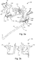
- Fig. 3a schematically illustrates a perspective view of a connection arrangement 110 for fluid connection of two separate liquefied gas fuel tanks TM, TS for providing fuel to the engine of a vehicle and fig. 3b schematically illustrates a front view of the connection arrangement 110 in fig. 3a .
- the fuel tanks TM, TS have here been denoted the same reference signs as in the embodiment in fig. 2 .
- connection arrangement 110 functionally corresponds to the connection arrangement 10.
- the connection arrangement 10 in fig. 2 is more generally illustrated.
- the connection arrangement 110 in fig. 3a-b , fig. 4 and fig. 5 according to an embodiment essentially corresponds to the connection arrangement in fig. 2 .
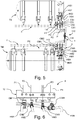
- Fig. 4 schematically illustrates a perspective view of the connection arrangement in fig. 3 connected to fuel tanks
- fig. 5 schematically illustrates a plan view of the connection arrangement in fig. 4
- fig. 6 schematically illustrates a detail of the connection arrangement in fig. 5 .
- the connection arrangement comprises a set of pipes P.
- the set of pipes P comprises a first pipe P1 configured for transporting liquefied gas, i.e. liquefied natural gas, LNG, or liquefied biogas LBG.
- liquefied gas i.e. liquefied natural gas, LNG, or liquefied biogas LBG.
- the set of pipes P comprises a second pipe P2 configured for venting in connection to refuelling the tanks TM, TS.
- the set of pipes P comprises a third pipe P3 configured for venting of boil-off gas.
- the set of pipes P comprises a fourth pipe P4 configured for transporting the gas fuel to the engine.
- connection arrangement 110 comprises an interface element 112, 114 for the respective tank TM, TS.
- the interface element 112, 114 for the respective tank TM, TS comprises a left interface element 112.
- the left interface element 112 is arranged to be connected to the left longitudinal beam 2 of the vehicle frame as illustrated in fig. 5 .
- the left interface element 112 has an upper portion 112a, see fig. 3a , for connecting the left interface 112 to the left longitudinal beam 2 by means of fastening members F1, F2, according to an embodiment screw members, see fig. 3b .
- the left interface element 112 has a lower portion 112b, see fig. 3a .
- the interface element 112, 114 for the respective tank TM, TS comprises a right interface element 114.
- the right interface element 114 is arranged to be connected to the right longitudinal beam 3 of the vehicle as illustrated in fig. 5 .
- the right interface element 114 has an upper portion 114a, see fig. 3a , for connecting the right interface 114 to the right longitudinal beam 3 by means of fastening members F3, F4, according to an embodiment screw members, see fig. 3b .
- the right interface element 114 has a lower portion 114b, see fig. 3a .
- the connection arrangement 110 comprises a set of flexible hoses HM, HS directly connected to the respective tank TM, TS.
- the set of flexible hoses HM, HS comprises a set of hoses HM directly connected to the main tank TM and a set of hoses directly connected to the auxiliary tank TS.
- the set of flexible hoses HM directly connected to the main tank TM comprises a first hose HM1 configured for transporting liquefied gas, i.e. liquefied natural gas, LNG, or liquefied biogas LBG.
- the first hose HM1 is connected to one end of the first pipe P1 via the left interface element 112.
- the first hose HM1 is coupled to the first pipe via coupling member CM1.
- the coupling member CM1 comprises according to an embodiment a ferrule coupling.
- the set of flexible hoses HM directly connected to the main tank TM comprises a second hose HM2 configured for venting in connection to refuelling the tanks TM, TS.
- the second hose HM2 is connected to one end of the second pipe P2 via the left interface element 112.
- the second hose HM2 is coupled to the second pipe via coupling member CM2.
- the coupling member CM2 comprises according to an embodiment a ferrule coupling.
- the coupling member has a T-coupling configuration for connecting a pipe P5 for said venting.
- the set of flexible hoses HM directly connected to the main tank TM comprises a third hose HM3 configured for venting in connection to decoction.
- the third hose HM3 is connected to one end of the third pipe P3 via the left interface element 112.
- the third hose HM3 is coupled to the third pipe via coupling member CM3.
- the coupling member CM3 comprises according to an embodiment a ferrule coupling.
- the set of flexible hoses HM directly connected to the main tank HM comprises a fourth hose HM4 configured for transporting the gas fuel to the engine.
- the fourth hose H4 is connected to one end of the fourth pipe P4 via the left interface element 112.
- the fourth hose HM4 is coupled to the fourth pipe via coupling member CM4.
- the coupling member CM4 comprises according to an embodiment a ferrule coupling.
- the coupling member has a T-coupling configuration for connecting a pipe PE for transporting the gas fuel to the engine. Gas transported via the pipe PE to the engine will be gas fuel from the tank TM, TS having the highest pressure.
- the set of flexible hoses HS directly connected to the auxiliary tank TS comprises a first hose HS1 configured for transporting liquefied gas, i.e. liquefied natural gas, LNG, or liquefied biogas LBG.
- the first hose HS1 is connected to the opposite end of the first pipe P1 via the left interface element 112.
- the first hose HS1 is coupled to the first pipe via coupling member CS1.
- the coupling member CS1 comprises according to an embodiment a ferrule coupling.
- the set of flexible hoses HM directly connected to the auxiliary tank TS comprises a second hose HS2 configured for venting in connection to refuelling the tanks HS, TS.
- the second hose HS2 is connected to the opposite end of the second pipe P2 via the left interface element 112.
- the second hose HS2 is coupled to the second pipe via coupling member CS2.
- the coupling member CS2 comprises according to an embodiment a ferrule coupling.
- the set of flexible hoses HM directly connected to the auxiliary tank TS comprises a third hose HS3 configured for venting in connection to decoction.
- the third hose HS3 is connected to the opposite end of the third pipe P3 via the left interface element 112.
- the third hose HS3 is coupled to the third pipe via coupling member CS3.
- the coupling member CS3 comprises according to an embodiment a ferrule coupling.
- the set of flexible hoses HM directly connected to the auxiliary tank TS comprises a fourth hose HS4 configured for transporting the gas fuel to the engine.
- the fourth hose HS4 is connected to the opposite end of the fourth pipe P4 via the left interface element 112.
- the fourth hose HS4 is coupled to the fourth pipe via coupling member CS4.
- the coupling member CS4 comprises according to an embodiment a ferrule coupling.
- the coupling members CM1-CM4, CS1-CS4 may be any suitable coupling.
- the coupling members CM1-CM4, CS1-CS4 being a ferrule coupling may be a double ferrule coupling.
- the coupling members could also comprise a cutting ring fitting.
- the set of flexible hoses HM, HS for the respective tank TM, TS are thus connected to the set of pipes P via the respective interface element 112, 114.
- the set of flexible hoses HM, HS for the respective tank TM, TS are connected to the set of pipes P via the lower portion 112b, 114b of the respective interface element 112, 114 by means of connecting elements.
- the connection arrangement 110 comprises a support element 116 for said set of pipes P arranged between said interface elements 112, 114.
- the support element 116 is arranged to be connected to the crossbeam 4 of the vehicle frame, see fig. 5 .
- the support element 116 is thus arranged to support the set of pipes P.
- the set of pipes P are connected to the support element 116 via connecting elements C1, C2, C3, C4.
- the first pipe P1 is connected to the support element 116 via a first connecting element C1.
- the second pipe P2 is connected to the support element 116 via a second connecting element C2.
- the third pipe P3 is connected to the support element 116 via a third connecting element C3.
- the fourth pipe P4 is connected to the support element 116 via a fourth connecting element C4.
- the risk of built in tensions in the system is reduced in that the pipes P are connected via said interface elements 12, 14 to the flexible hoses HM, HS and may thereby be subjected to less tensions. Easier installation and maintenance is hereby facilitated.
- the main tank TM is arranged to be connected to the left longitudinal beam 2 of the vehicle frame via fastening elements M1, M2, M3; M4
- the auxiliary tank TS is arranged to be connected to the right longitudinal beam 2 of the vehicle frame via fastening elements S1, S2, S3.
- the interface elements 112, 114 are comprised in an arrangement for a liquefied gas fuel system for a vehicle according to an embodiment of the present invention.
- the support element 116 is according to an embodiment comprised in said arrangement for a liquefied gas fuel system.
- the connection arrangement 110 is according to an embodiment comprised in said arrangement for a liquefied gas fuel system.
Landscapes
- Engineering & Computer Science (AREA)
- Chemical & Material Sciences (AREA)
- Mechanical Engineering (AREA)
- Combustion & Propulsion (AREA)
- General Engineering & Computer Science (AREA)
- Transportation (AREA)
- Life Sciences & Earth Sciences (AREA)
- Sustainable Energy (AREA)
- Sustainable Development (AREA)
- Chemical Kinetics & Catalysis (AREA)
- General Chemical & Material Sciences (AREA)
- Oil, Petroleum & Natural Gas (AREA)
- Cooling, Air Intake And Gas Exhaust, And Fuel Tank Arrangements In Propulsion Units (AREA)
- Filling Or Discharging Of Gas Storage Vessels (AREA)
Description
- The invention relates to an arrangement for a liquefied gas fuel system for a vehicle. The invention also relates to a vehicle.
- Alternative fuels such as natural gas and biogas are being introduced in vehicles such as heavy vehicles. For this purpose fuel systems for compressed natural gas, CNG and compressed biogas CBG and fuel systems for liquefied natural gas LNG and liquefied biogas LBG are being developed.
- Systems for liquefied gas, i.e. LNG and LBG, require handling of relatively low temperatures, e.g. -130 degrees at 10 bar for LNG, requiring certain conduits for transporting the liquefied natural gas. Further, in order to provide sufficient fuel to be able to travel desired distances, liquefied gas fuel tanks of a certain volume are required. For this purpose it is common to provide dual liquefied gas tanks, one at each side of the vehicle frame.
- Liquefied natural gas, LNG, used as fuel for gas trucks is currently transported in rigid pipes from the fuel tank to the engine and venting system. The pipes are long and difficult to mount, especially if the trucks have dual tanks. Further, tensions are often built into such liquefied natural gas systems.
- Document
US2014/150884A1 discloses a liquid gas system for vehicles, the system comprises two gas reservoirs, connected via feed lines to a changeover switch concurrently integrating a pressure regulator. The changeover switch works as follows: when two full gas reservoirs are connected, the changeover switch is adjusted so that gas is withdrawn from the preselected gas reservoir. When this gas reservoir runs empty, the changeover switch automatically switches over to the second full gas reservoir. - Document
US2014/137953A1 discloses a compressed natural gas fuel system comprising a frame, a first container, a second container, a first manifold, a second manifold, and a casing. The first manifold may be engaged to and substantially shrouded by the first side of the frame. The second manifold may be engaged to and substantially shrouded by the second side of the frame. - An object of the present invention is to provide an arrangement for a liquefied gas fuel system for a vehicle which facilitates mounting of the system. Another object of the present invention is to provide an arrangement for a liquefied gas fuel system for a vehicle which reduces risk of built in tensions in the system.
- These and other objects, apparent from the following description, are achieved by an arrangement and a vehicle as set out in the appended independent claim. Preferred embodiments of the arrangement are defined in appended dependent claims.
- Specifically an object of the invention is achieved by an arrangement for a liquefied gas fuel system for a vehicle according to
claim 1. Said fuel system has two separate liquefied gas fuel tanks for providing fuel to the engine of the vehicle. Said installation of the piping and an easier handling at maintenance. Another advantage is that fewer bendings will allow a less limited flow in the liquefied gas fuel system. - The combination of pipes and hoses provides stiffness provided by the pipes where desirable, for example near the propeller shaft where collisions need to be avoided, and is less costly than an alternative only consisting of hoses.
- According to an embodiment of the arrangement the respective interface elements are arranged to support said set of pipes. Hereby the risk of built in tensions in the system is further reduced.
- According to an embodiment of the arrangement said connection arrangement comprises a support element for said set of pipes arranged between said interface elements. Hereby the risk of built in tensions in the system is further reduced.
- According to an embodiment of the arrangement one interface element is arranged to be connected to one longitudinal side of the vehicle frame and the other interface element is arranged to be connected to the opposite longitudinal side of the vehicle frame.
- Hereby an efficient construction for tanks arranged in connection to the respective longitudinal side of the vehicle frame is obtained. By thus arranging the interface elements in connection to the respective side of the longitudinal side of the vehicle frame efficient support for the pipes is facilitated.
- According to an embodiment of the arrangement said support element is arranged to be connected to a crossbeam of the vehicle frame. Hereby the risk of built in tensions in the system is further reduced.
- According to an embodiment of the arrangement said liquefied gas fuel is liquefied natural gas, LNG, or liquefied biogas, LBG.
- Specifically an object of the invention is achieved by a vehicle comprising an arrangement as set out herein.
- For a better understanding of the present invention reference is made to the following detailed description when read in conjunction with the accompanying drawings, wherein like reference characters refer to like parts throughout the several views, and in which:
-
Fig. 1 schematically illustrates a perspective view of a vehicle with a liquefied gas fuel system; -
Fig. 2 schematically illustrates plan view of the vehicle infig. 1 with an arrangement for a liquefied gas fuel system according to an embodiment of the present invention; -
Fig. 3a schematically illustrates a perspective view of a connection arrangement for fluid connection of two separate liquefied gas fuel tanks for providing fuel to the engine of a vehicle; -
Fig. 3b schematically illustrates a front view of the connection arrangement infig. 3a ; -
Fig. 4 schematically illustrates a perspective view of the connection arrangement infig. 3 connected to fuel tanks; -
Fig. 5 schematically illustrates a plan view of the connection arrangement infig. 4 ; and -
Fig. 6 schematically illustrates a detail of the connection arrangement infig. 5 . - Hereinafter the term "liquefied gas" refers to liquefied natural gas, LNG, or liquefied biogas, LBG.
- Hereinafter the term "liquefied gas fuel system" refers to a fuel system for liquefied natural gas, LNG, or a fuel system for liquefied biogas, LBG.
- Hereinafter the term "flexible hoses" refers to hoses configured to transport fluids for a liquefied gas fuel system being bendable to a certain degree and having a certain flexibility so as to facilitate connection to fuel tanks. The hoses are according to an embodiment made of Polytetrafluoroethylene (PTFE) or internally lined with a layer of PTFE in order to benefit from the methane resistant properties of PTFE.
- Hereinafter the term "pipes" refers to rigid pipes configured to transport fluids for a liquefied gas fuel system which do not provide any flexibility or bendability in comparison to said flexible hoses. The pipes are according to an embodiment made of stainless steel. The pipes may also be made of copper.
-
Fig. 1 schematically illustrates a side view of avehicle 1 according to the present invention. The exemplifiedvehicle 1 is a heavy vehicle in the shape of a truck. The vehicle according to the present invention could be any suitable vehicle. The vehicle comprises an arrangement for a liquefied gas fuel system for a vehicle. - The vehicle comprises a
vehicle frame longitudinal vehicle beam 2 and a rightlongitudinal vehicle beam 3. - The vehicle comprises a left liquefied gas fuel tank TM arranged in connection to the left
longitudinal vehicle beam 2 and a right liquefied gas fuel tank TS arranged in connection to the rightlongitudinal beam 3. The tanks TM, TS have an essentially cylindrical shape and are arranged on the respective side of the longitudinal vehicle beams 2, 3 axially extending along the respectivelongitudinal beam -
Fig. 2 schematically illustrates plan view of the vehicle infig. 1 with thevehicle frame vehicle frame longitudinal vehicle beam 2 and a rightlongitudinal vehicle beam 3. Thevehicle frame crossbeam 4 arranged a support between the left and rightlongitudinal beams - The exemplified
vehicle 1 is a heavy vehicle in the shape of a truck. Thevehicle 1 in this embodiment has a forward wheeled axle X1 with opposite front wheels and a powered rear wheeled axle X2 with opposite tractive wheels. - The
vehicle 1 comprises a liquefied gas fuel system I. The fuel system I comprises the two separate liquefied tanks TM, TS for providing fuel to the engine E of thevehicle 1 via a pipe PE, a left liquefied gas fuel tank TM arranged in connection to the leftlongitudinal vehicle beam 2 and a right liquefied gas fuel tank TS arranged in connection to the rightlongitudinal beam 3. The tanks TM, TS are arranged on the respective side of the longitudinal vehicle beams 2, 3 axially extending along the respectivelongitudinal beam - The left liquefied gas fuel tank TM is denoted the main tank TM and the right liquefied gas fuel tank TS is denoted the auxiliary tank TS of the dual tank installation. The tank TM may also be denoted master tank and the tank TS may also be denoted slave tank.
- The fuel system I comprises a
connection arrangement 10. The main tank TM and auxiliary tank TS are in in fluid communication via theconnection arrangement 10. - The connection arrangement comprises a set of pipes P.
- The
connection arrangement 10 comprises aninterface element - The
interface element left interface element 12 arranged to be connected to the leftlongitudinal beam 2 of thevehicle frame - The
interface element right interface element 14 arranged to be connected to the rightlongitudinal beam 3 of thevehicle frame - The
connection arrangement 10 comprises a set of hoses HM, HS directly connected to the respective tank TM, TS. The set of hoses HM, HS comprises a set of hoses HM directly connected to the main tank TM and a set of hoses directly connected to the auxiliary tank TS. - The set of flexible hoses HM, HS for the respective tank TM, TS are connected to the set of pipes via the
respective interface element interface element 12. The set of hoses HM directly connected to the main tank TM are thus connected to one set of ends of the set of pipes P via theinterface element 12. The set of hoses HS directly connected to the auxiliary tank TS are connected to the set of pipes P via theinterface element 14. The set of hoses HS directly connected to the auxiliary tank TS are thus connected to the opposite set of ends of the set of pipes P via theinterface element 14. - The
connection arrangement 10 comprises asupport element 16 for said set of pipes P arranged between saidinterface elements support element 16 is arranged to be connected to thecrossbeam 4 of thevehicle frame support element 16 is thus arranged to support the set of pipes P. The set of pipes P are connected to thesupport element 16. Thesupport element 16 thus functions as a crossbeam pipe bracket. - By thus connecting flexible hoses HM, HS via the
respective interface element interface elements -
Fig. 3a schematically illustrates a perspective view of aconnection arrangement 110 for fluid connection of two separate liquefied gas fuel tanks TM, TS for providing fuel to the engine of a vehicle andfig. 3b schematically illustrates a front view of theconnection arrangement 110 infig. 3a . The fuel tanks TM, TS have here been denoted the same reference signs as in the embodiment infig. 2 . - The
connection arrangement 110 according to this embodiment functionally corresponds to theconnection arrangement 10. Theconnection arrangement 10 infig. 2 is more generally illustrated. Theconnection arrangement 110 infig. 3a-b ,fig. 4 andfig. 5 according to an embodiment essentially corresponds to the connection arrangement infig. 2 . -
Fig. 4 schematically illustrates a perspective view of the connection arrangement infig. 3 connected to fuel tanks,fig. 5 schematically illustrates a plan view of the connection arrangement infig. 4 andfig. 6 schematically illustrates a detail of the connection arrangement infig. 5 . - The connection arrangement comprises a set of pipes P.
- The set of pipes P comprises a first pipe P1 configured for transporting liquefied gas, i.e. liquefied natural gas, LNG, or liquefied biogas LBG.
- The set of pipes P comprises a second pipe P2 configured for venting in connection to refuelling the tanks TM, TS.
- The set of pipes P comprises a third pipe P3 configured for venting of boil-off gas.
- The set of pipes P comprises a fourth pipe P4 configured for transporting the gas fuel to the engine.
- The
connection arrangement 110 comprises aninterface element - The
interface element left interface element 112. Theleft interface element 112 is arranged to be connected to the leftlongitudinal beam 2 of the vehicle frame as illustrated infig. 5 . Theleft interface element 112 has anupper portion 112a, seefig. 3a , for connecting theleft interface 112 to the leftlongitudinal beam 2 by means of fastening members F1, F2, according to an embodiment screw members, seefig. 3b . Theleft interface element 112 has alower portion 112b, seefig. 3a . - The
interface element right interface element 114. Theright interface element 114 is arranged to be connected to the rightlongitudinal beam 3 of the vehicle as illustrated infig. 5 . Theright interface element 114 has anupper portion 114a, seefig. 3a , for connecting theright interface 114 to the rightlongitudinal beam 3 by means of fastening members F3, F4, according to an embodiment screw members, seefig. 3b . Theright interface element 114 has alower portion 114b, seefig. 3a . - The
connection arrangement 110 comprises a set of flexible hoses HM, HS directly connected to the respective tank TM, TS. The set of flexible hoses HM, HS comprises a set of hoses HM directly connected to the main tank TM and a set of hoses directly connected to the auxiliary tank TS. - The set of flexible hoses HM directly connected to the main tank TM comprises a first hose HM1 configured for transporting liquefied gas, i.e. liquefied natural gas, LNG, or liquefied biogas LBG. The first hose HM1 is connected to one end of the first pipe P1 via the
left interface element 112. The first hose HM1 is coupled to the first pipe via coupling member CM1. The coupling member CM1 comprises according to an embodiment a ferrule coupling. - The set of flexible hoses HM directly connected to the main tank TM comprises a second hose HM2 configured for venting in connection to refuelling the tanks TM, TS. The second hose HM2 is connected to one end of the second pipe P2 via the
left interface element 112. The second hose HM2 is coupled to the second pipe via coupling member CM2. The coupling member CM2 comprises according to an embodiment a ferrule coupling. The coupling member has a T-coupling configuration for connecting a pipe P5 for said venting. - The set of flexible hoses HM directly connected to the main tank TM comprises a third hose HM3 configured for venting in connection to decoction. The third hose HM3 is connected to one end of the third pipe P3 via the
left interface element 112. The third hose HM3 is coupled to the third pipe via coupling member CM3. The coupling member CM3 comprises according to an embodiment a ferrule coupling. - The set of flexible hoses HM directly connected to the main tank HM comprises a fourth hose HM4 configured for transporting the gas fuel to the engine. The fourth hose H4 is connected to one end of the fourth pipe P4 via the
left interface element 112. The fourth hose HM4 is coupled to the fourth pipe via coupling member CM4. The coupling member CM4 comprises according to an embodiment a ferrule coupling. The coupling member has a T-coupling configuration for connecting a pipe PE for transporting the gas fuel to the engine. Gas transported via the pipe PE to the engine will be gas fuel from the tank TM, TS having the highest pressure. - The set of flexible hoses HS directly connected to the auxiliary tank TS comprises a first hose HS1 configured for transporting liquefied gas, i.e. liquefied natural gas, LNG, or liquefied biogas LBG. The first hose HS1 is connected to the opposite end of the first pipe P1 via the
left interface element 112. The first hose HS1 is coupled to the first pipe via coupling member CS1. The coupling member CS1 comprises according to an embodiment a ferrule coupling. - The set of flexible hoses HM directly connected to the auxiliary tank TS comprises a second hose HS2 configured for venting in connection to refuelling the tanks HS, TS. The second hose HS2 is connected to the opposite end of the second pipe P2 via the
left interface element 112. The second hose HS2 is coupled to the second pipe via coupling member CS2. The coupling member CS2 comprises according to an embodiment a ferrule coupling. - The set of flexible hoses HM directly connected to the auxiliary tank TS comprises a third hose HS3 configured for venting in connection to decoction. The third hose HS3 is connected to the opposite end of the third pipe P3 via the
left interface element 112. The third hose HS3 is coupled to the third pipe via coupling member CS3. The coupling member CS3 comprises according to an embodiment a ferrule coupling. - The set of flexible hoses HM directly connected to the auxiliary tank TS comprises a fourth hose HS4 configured for transporting the gas fuel to the engine. The fourth hose HS4 is connected to the opposite end of the fourth pipe P4 via the
left interface element 112. The fourth hose HS4 is coupled to the fourth pipe via coupling member CS4. The coupling member CS4 comprises according to an embodiment a ferrule coupling. - The coupling members CM1-CM4, CS1-CS4 may be any suitable coupling. The coupling members CM1-CM4, CS1-CS4 being a ferrule coupling may be a double ferrule coupling. The coupling members could also comprise a cutting ring fitting.
- The set of flexible hoses HM, HS for the respective tank TM, TS are thus connected to the set of pipes P via the
respective interface element lower portion respective interface element - The
connection arrangement 110 comprises asupport element 116 for said set of pipes P arranged between saidinterface elements support element 116 is arranged to be connected to thecrossbeam 4 of the vehicle frame, seefig. 5 . Thesupport element 116 is thus arranged to support the set of pipes P. The set of pipes P are connected to thesupport element 116 via connecting elements C1, C2, C3, C4. The first pipe P1 is connected to thesupport element 116 via a first connecting element C1. The second pipe P2 is connected to thesupport element 116 via a second connecting element C2. The third pipe P3 is connected to thesupport element 116 via a third connecting element C3. The fourth pipe P4 is connected to thesupport element 116 via a fourth connecting element C4. - By thus connecting flexible hoses HM1, HM2, HM3, HM4, HS1, HS2, HS3, HS4 via the
respective interface element interface elements - The main tank TM is arranged to be connected to the left
longitudinal beam 2 of the vehicle frame via fastening elements M1, M2, M3; M4 The auxiliary tank TS is arranged to be connected to the rightlongitudinal beam 2 of the vehicle frame via fastening elements S1, S2, S3. - The
interface elements support element 116 is according to an embodiment comprised in said arrangement for a liquefied gas fuel system. Theconnection arrangement 110 is according to an embodiment comprised in said arrangement for a liquefied gas fuel system. - The foregoing description of the preferred embodiments of the present invention has been provided for the purposes of illustration and description. It is not intended to be exhaustive or to limit the invention to the precise forms disclosed. Obviously, many modifications and variations are possible within the scope of the appended claims and will be apparent to practitioners skilled in the art. The embodiments were chosen and described in order to best explain the principles of the invention and its practical applications, thereby enabling others skilled in the art to understand the invention for various embodiments and with the various modifications as are suited to the particular use contemplated.
Claims (7)
- An arrangement for a liquefied gas fuel system for a vehicle (1), said fuel system having two separate liquefied gas fuel tanks (TM, TS) for providing fuel to the engine (E) of the vehicle (1), said fuel tanks (TM, TS) being in fluid communication via a connection arrangement (10; 110) comprising a set of rigid pipes (P), characterized in that said connection arrangement (10; 110) comprises interface elements (12, 14; 112, 114) for the respective tank (TM, TS) and a set of flexible hoses (HM, HS) directly connected to the respective tank (TM, TS), wherein the set of flexible hoses (HM, HS) for the respective tank (TM, TS) are connected to the set of rigid pipes (P) via the respective interface elements (12, 14; 112, 114).
- An arrangement according to claim 1, wherein the respective interface elements (12, 14; 112, 114) are arranged to support said set of rigid pipes (P).
- An arrangement according to claim 1 or 2, wherein said connection arrangement (10; 110) comprises a support element (16; 116) for said set of rigid pipes (P) arranged between said interface elements (12, 14; 112, 114).
- An arrangement according to any of claims 1-3, wherein one interface element (12; 112) is arranged to be connected to one longitudinal side (2) of the vehicle frame and the other interface element (14; 114) is arranged to be connected to the opposite longitudinal side (3) of the vehicle frame.
- An arrangement according to any of claims 1-4, wherein said support element (16; 116) is arranged to be connected to a crossbeam (4) of the vehicle frame.
- An arrangement according to any of claims 1-5, wherein said liquefied gas fuel is liquefied natural gas, LNG, or liquefied biogas, LBG.
- A vehicle (1) comprising an arrangement according to any of claims 1-6.
Applications Claiming Priority (2)
| Application Number | Priority Date | Filing Date | Title |
|---|---|---|---|
| SE1650560A SE540106C2 (en) | 2016-04-27 | 2016-04-27 | A connection arrangement for a liquefied gas fuel system for a vehicle |
| PCT/SE2017/050400 WO2017188882A1 (en) | 2016-04-27 | 2017-04-24 | An arrangement for a liquefied gas fuel system for a vehicle |
Publications (3)
| Publication Number | Publication Date |
|---|---|
| EP3449175A1 EP3449175A1 (en) | 2019-03-06 |
| EP3449175A4 EP3449175A4 (en) | 2019-12-18 |
| EP3449175B1 true EP3449175B1 (en) | 2021-03-24 |
Family
ID=60159902
Family Applications (1)
| Application Number | Title | Priority Date | Filing Date |
|---|---|---|---|
| EP17790015.6A Active EP3449175B1 (en) | 2016-04-27 | 2017-04-24 | An arrangement for a liquefied gas fuel system for a vehicle |
Country Status (6)
| Country | Link |
|---|---|
| EP (1) | EP3449175B1 (en) |
| KR (1) | KR102226701B1 (en) |
| CN (1) | CN109073160B (en) |
| BR (1) | BR112018069570B1 (en) |
| SE (1) | SE540106C2 (en) |
| WO (1) | WO2017188882A1 (en) |
Cited By (1)
| Publication number | Priority date | Publication date | Assignee | Title |
|---|---|---|---|---|
| EP4403395A1 (en) * | 2023-01-18 | 2024-07-24 | Friedrich Boysen GmbH & Co. KG | Tank system |
Families Citing this family (3)
| Publication number | Priority date | Publication date | Assignee | Title |
|---|---|---|---|---|
| JP7103250B2 (en) * | 2019-01-31 | 2022-07-20 | トヨタ自動車株式会社 | Fuel cell vehicle |
| JP7205510B2 (en) * | 2020-03-10 | 2023-01-17 | いすゞ自動車株式会社 | Fuel hose routing structure |
| DE112023000055A5 (en) | 2022-09-19 | 2024-05-23 | Quantron Ag | VEHICLE AND METHOD FOR FILLING A FUEL TANK OF SUCH A VEHICLE |
Family Cites Families (17)
| Publication number | Priority date | Publication date | Assignee | Title |
|---|---|---|---|---|
| KR100325737B1 (en) * | 1999-06-17 | 2002-03-06 | 류정열 | Connection Structure of Assembly Multi-line Fuel Tank of Cars Using LPG |
| JP3627670B2 (en) * | 2001-05-16 | 2005-03-09 | 日産自動車株式会社 | High pressure gas container mounting structure |
| CA2386443C (en) * | 2001-05-17 | 2007-10-23 | Dynetek Industries Ltd. | Replaceable fuel module and method |
| JP3823806B2 (en) * | 2001-10-30 | 2006-09-20 | 日産自動車株式会社 | Support structure for high pressure vessel |
| KR20030083384A (en) * | 2002-04-22 | 2003-10-30 | 현대자동차주식회사 | Mounting structure of fuel feeding control unit in truck using compressed natural gas |
| JP5023548B2 (en) * | 2006-05-01 | 2012-09-12 | 井関農機株式会社 | Tractor |
| DE102007035977B4 (en) * | 2007-08-01 | 2009-07-16 | Toptron Gmbh | Electronic flow sensor |
| BRPI0823369B1 (en) * | 2008-12-12 | 2020-02-04 | Volvo Lastvagnar Ab | tank and vehicle layout with a tank layout |
| US8807256B2 (en) * | 2012-11-21 | 2014-08-19 | Trilogy Engineered Solutions, LLC | Methods and systems for compressed natural gas (CNG) |
| US9592731B2 (en) * | 2013-10-22 | 2017-03-14 | Shem, Llc | CNG fuel system for a vehicle |
| CN203567551U (en) * | 2013-10-29 | 2014-04-30 | 武汉亚普汽车塑料件有限公司 | Saddle-shaped automobile fuel tank |
| KR20160017787A (en) * | 2014-08-05 | 2016-02-17 | 현대중공업 주식회사 | Moss type lng and gascarrier |
| DE202014006478U1 (en) * | 2014-08-08 | 2014-08-29 | Heliocentris Energy Solutions Ag | Valve system for gas cylinder bundles |
| CN204623141U (en) * | 2015-04-30 | 2015-09-09 | 安徽安凯汽车股份有限公司 | A kind of Double-layer bus tank pressure balanced structure |
| CN105015323A (en) * | 2015-07-21 | 2015-11-04 | 宁波舜江汽车部件制造有限公司 | Oil filling pipe assembly with flexible structure |
| CN204937447U (en) * | 2015-09-08 | 2016-01-06 | 江南造船(集团)有限责任公司 | The arrangement structure of liquefied gas carrier fuel storage facility and gas supply system |
| CN205086915U (en) * | 2015-10-30 | 2016-03-16 | 中车资阳机车有限公司 | Two fuel locomotive's safety guarantee system |
-
2016
- 2016-04-27 SE SE1650560A patent/SE540106C2/en unknown
-
2017
- 2017-04-24 WO PCT/SE2017/050400 patent/WO2017188882A1/en not_active Ceased
- 2017-04-24 KR KR1020187032112A patent/KR102226701B1/en active Active
- 2017-04-24 BR BR112018069570-0A patent/BR112018069570B1/en active IP Right Grant
- 2017-04-24 CN CN201780024306.2A patent/CN109073160B/en active Active
- 2017-04-24 EP EP17790015.6A patent/EP3449175B1/en active Active
Non-Patent Citations (1)
| Title |
|---|
| None * |
Cited By (1)
| Publication number | Priority date | Publication date | Assignee | Title |
|---|---|---|---|---|
| EP4403395A1 (en) * | 2023-01-18 | 2024-07-24 | Friedrich Boysen GmbH & Co. KG | Tank system |
Also Published As
| Publication number | Publication date |
|---|---|
| BR112018069570A2 (en) | 2019-01-29 |
| EP3449175A4 (en) | 2019-12-18 |
| SE540106C2 (en) | 2018-03-27 |
| SE1650560A1 (en) | 2017-10-28 |
| KR20180133885A (en) | 2018-12-17 |
| CN109073160B (en) | 2021-11-02 |
| CN109073160A (en) | 2018-12-21 |
| KR102226701B1 (en) | 2021-03-12 |
| WO2017188882A1 (en) | 2017-11-02 |
| EP3449175A1 (en) | 2019-03-06 |
| BR112018069570B1 (en) | 2023-01-17 |
Similar Documents
| Publication | Publication Date | Title |
|---|---|---|
| EP3449175A1 (en) | An arrangement for a liquefied gas fuel system for a vehicle | |
| US9187982B2 (en) | Apparatus and methods for providing natural gas to multiple engines disposed upon multiple carriers | |
| US5603360A (en) | Method and system for transporting natural gas from a pipeline to a compressed natural gas automotive re-fueling station | |
| EP3509887B1 (en) | An arrangement for mounting a gas pipe in a vehicle | |
| CN205065271U (en) | Multi -functional LNG integration loading and unloading sledge | |
| CN110062711A (en) | Apparatus for mounting evaporative pipes of liquefied gas fuel systems to vehicles | |
| CN110494353B (en) | Ship with a detachable cover | |
| EP1688660A1 (en) | Mobile lng/cng supply station | |
| US20230073632A1 (en) | Method and system for transporting hydrogen gas via a pipeline | |
| WO2020076210A1 (en) | An arrangement for facilitating evacuating evaporated liquefied gas of a liquefied gas fuel system of a vehicle | |
| EP2761218B1 (en) | Line and delivery system having such a line | |
| US9777682B2 (en) | Fuel tank assembly having crossover tube | |
| EP3509889B1 (en) | An arrangement for mounting a boil-off pipe of a liquefied gas fuel system to a vehicle | |
| WO2020076209A1 (en) | An arrangement for facilitating evacuating evaporated liquefied gas of a liquefied gas fuel system of a vehicle | |
| IL302501A (en) | Hydraulic unit for carbonated water tanks | |
| CN220745380U (en) | Filling pump and crane position batch control device | |
| KR101818518B1 (en) | Apparatus for transferring fluid | |
| CN202687938U (en) | Novel double-fuel refueling truck | |
| CN219062747U (en) | Pipeline assembly and gas conveying equipment | |
| CN111602000A (en) | Method and system for supplying liquefied gas | |
| WO2024076239A1 (en) | Device for transferring liquid | |
| WO2023097156A3 (en) | Oil delivery process with bulk oil quality control | |
| ES1044439U (en) | System settings refueling aircraft fuel units as autonomous and suitable for the transport of dangerous goods by road semitrailers. (Machine-translation by Google Translate, not legally binding) | |
| TW466316B (en) | Compressed fuel gas transportation and distribution system | |
| DE50004979D1 (en) | Inliner for transport containers |
Legal Events
| Date | Code | Title | Description |
|---|---|---|---|
| STAA | Information on the status of an ep patent application or granted ep patent |
Free format text: STATUS: THE INTERNATIONAL PUBLICATION HAS BEEN MADE |
|
| PUAI | Public reference made under article 153(3) epc to a published international application that has entered the european phase |
Free format text: ORIGINAL CODE: 0009012 |
|
| STAA | Information on the status of an ep patent application or granted ep patent |
Free format text: STATUS: REQUEST FOR EXAMINATION WAS MADE |
|
| 17P | Request for examination filed |
Effective date: 20181127 |
|
| AK | Designated contracting states |
Kind code of ref document: A1 Designated state(s): AL AT BE BG CH CY CZ DE DK EE ES FI FR GB GR HR HU IE IS IT LI LT LU LV MC MK MT NL NO PL PT RO RS SE SI SK SM TR |
|
| AX | Request for extension of the european patent |
Extension state: BA ME |
|
| DAV | Request for validation of the european patent (deleted) | ||
| DAX | Request for extension of the european patent (deleted) | ||
| A4 | Supplementary search report drawn up and despatched |
Effective date: 20191119 |
|
| RIC1 | Information provided on ipc code assigned before grant |
Ipc: F02M 21/02 20060101ALI20191113BHEP Ipc: B60K 15/01 20060101ALI20191113BHEP Ipc: F17C 1/00 20060101ALI20191113BHEP Ipc: B60K 15/07 20060101ALI20191113BHEP Ipc: F17C 13/08 20060101AFI20191113BHEP Ipc: B60K 15/03 20060101ALI20191113BHEP Ipc: F17C 13/12 20060101ALI20191113BHEP Ipc: B60K 15/063 20060101ALI20191113BHEP |
|
| GRAP | Despatch of communication of intention to grant a patent |
Free format text: ORIGINAL CODE: EPIDOSNIGR1 |
|
| STAA | Information on the status of an ep patent application or granted ep patent |
Free format text: STATUS: GRANT OF PATENT IS INTENDED |
|
| INTG | Intention to grant announced |
Effective date: 20201027 |
|
| GRAS | Grant fee paid |
Free format text: ORIGINAL CODE: EPIDOSNIGR3 |
|
| GRAA | (expected) grant |
Free format text: ORIGINAL CODE: 0009210 |
|
| STAA | Information on the status of an ep patent application or granted ep patent |
Free format text: STATUS: THE PATENT HAS BEEN GRANTED |
|
| AK | Designated contracting states |
Kind code of ref document: B1 Designated state(s): AL AT BE BG CH CY CZ DE DK EE ES FI FR GB GR HR HU IE IS IT LI LT LU LV MC MK MT NL NO PL PT RO RS SE SI SK SM TR |
|
| REG | Reference to a national code |
Ref country code: GB Ref legal event code: FG4D |
|
| REG | Reference to a national code |
Ref country code: CH Ref legal event code: EP |
|
| REG | Reference to a national code |
Ref country code: IE Ref legal event code: FG4D |
|
| REG | Reference to a national code |
Ref country code: AT Ref legal event code: REF Ref document number: 1374824 Country of ref document: AT Kind code of ref document: T Effective date: 20210415 Ref country code: DE Ref legal event code: R096 Ref document number: 602017035319 Country of ref document: DE |
|
| RAP4 | Party data changed (patent owner data changed or rights of a patent transferred) |
Owner name: SCANIA CV AB |
|
| REG | Reference to a national code |
Ref country code: LT Ref legal event code: MG9D |
|
| PG25 | Lapsed in a contracting state [announced via postgrant information from national office to epo] |
Ref country code: HR Free format text: LAPSE BECAUSE OF FAILURE TO SUBMIT A TRANSLATION OF THE DESCRIPTION OR TO PAY THE FEE WITHIN THE PRESCRIBED TIME-LIMIT Effective date: 20210324 Ref country code: FI Free format text: LAPSE BECAUSE OF FAILURE TO SUBMIT A TRANSLATION OF THE DESCRIPTION OR TO PAY THE FEE WITHIN THE PRESCRIBED TIME-LIMIT Effective date: 20210324 Ref country code: GR Free format text: LAPSE BECAUSE OF FAILURE TO SUBMIT A TRANSLATION OF THE DESCRIPTION OR TO PAY THE FEE WITHIN THE PRESCRIBED TIME-LIMIT Effective date: 20210625 Ref country code: NO Free format text: LAPSE BECAUSE OF FAILURE TO SUBMIT A TRANSLATION OF THE DESCRIPTION OR TO PAY THE FEE WITHIN THE PRESCRIBED TIME-LIMIT Effective date: 20210624 Ref country code: BG Free format text: LAPSE BECAUSE OF FAILURE TO SUBMIT A TRANSLATION OF THE DESCRIPTION OR TO PAY THE FEE WITHIN THE PRESCRIBED TIME-LIMIT Effective date: 20210624 |
|
| PG25 | Lapsed in a contracting state [announced via postgrant information from national office to epo] |
Ref country code: LV Free format text: LAPSE BECAUSE OF FAILURE TO SUBMIT A TRANSLATION OF THE DESCRIPTION OR TO PAY THE FEE WITHIN THE PRESCRIBED TIME-LIMIT Effective date: 20210324 Ref country code: RS Free format text: LAPSE BECAUSE OF FAILURE TO SUBMIT A TRANSLATION OF THE DESCRIPTION OR TO PAY THE FEE WITHIN THE PRESCRIBED TIME-LIMIT Effective date: 20210324 Ref country code: SE Free format text: LAPSE BECAUSE OF FAILURE TO SUBMIT A TRANSLATION OF THE DESCRIPTION OR TO PAY THE FEE WITHIN THE PRESCRIBED TIME-LIMIT Effective date: 20210324 |
|
| REG | Reference to a national code |
Ref country code: NL Ref legal event code: MP Effective date: 20210324 |
|
| REG | Reference to a national code |
Ref country code: AT Ref legal event code: MK05 Ref document number: 1374824 Country of ref document: AT Kind code of ref document: T Effective date: 20210324 |
|
| PG25 | Lapsed in a contracting state [announced via postgrant information from national office to epo] |
Ref country code: NL Free format text: LAPSE BECAUSE OF FAILURE TO SUBMIT A TRANSLATION OF THE DESCRIPTION OR TO PAY THE FEE WITHIN THE PRESCRIBED TIME-LIMIT Effective date: 20210324 |
|
| PG25 | Lapsed in a contracting state [announced via postgrant information from national office to epo] |
Ref country code: SM Free format text: LAPSE BECAUSE OF FAILURE TO SUBMIT A TRANSLATION OF THE DESCRIPTION OR TO PAY THE FEE WITHIN THE PRESCRIBED TIME-LIMIT Effective date: 20210324 Ref country code: AT Free format text: LAPSE BECAUSE OF FAILURE TO SUBMIT A TRANSLATION OF THE DESCRIPTION OR TO PAY THE FEE WITHIN THE PRESCRIBED TIME-LIMIT Effective date: 20210324 Ref country code: LT Free format text: LAPSE BECAUSE OF FAILURE TO SUBMIT A TRANSLATION OF THE DESCRIPTION OR TO PAY THE FEE WITHIN THE PRESCRIBED TIME-LIMIT Effective date: 20210324 Ref country code: EE Free format text: LAPSE BECAUSE OF FAILURE TO SUBMIT A TRANSLATION OF THE DESCRIPTION OR TO PAY THE FEE WITHIN THE PRESCRIBED TIME-LIMIT Effective date: 20210324 Ref country code: CZ Free format text: LAPSE BECAUSE OF FAILURE TO SUBMIT A TRANSLATION OF THE DESCRIPTION OR TO PAY THE FEE WITHIN THE PRESCRIBED TIME-LIMIT Effective date: 20210324 |
|
| PG25 | Lapsed in a contracting state [announced via postgrant information from national office to epo] |
Ref country code: SK Free format text: LAPSE BECAUSE OF FAILURE TO SUBMIT A TRANSLATION OF THE DESCRIPTION OR TO PAY THE FEE WITHIN THE PRESCRIBED TIME-LIMIT Effective date: 20210324 Ref country code: RO Free format text: LAPSE BECAUSE OF FAILURE TO SUBMIT A TRANSLATION OF THE DESCRIPTION OR TO PAY THE FEE WITHIN THE PRESCRIBED TIME-LIMIT Effective date: 20210324 Ref country code: PL Free format text: LAPSE BECAUSE OF FAILURE TO SUBMIT A TRANSLATION OF THE DESCRIPTION OR TO PAY THE FEE WITHIN THE PRESCRIBED TIME-LIMIT Effective date: 20210324 Ref country code: PT Free format text: LAPSE BECAUSE OF FAILURE TO SUBMIT A TRANSLATION OF THE DESCRIPTION OR TO PAY THE FEE WITHIN THE PRESCRIBED TIME-LIMIT Effective date: 20210726 Ref country code: IS Free format text: LAPSE BECAUSE OF FAILURE TO SUBMIT A TRANSLATION OF THE DESCRIPTION OR TO PAY THE FEE WITHIN THE PRESCRIBED TIME-LIMIT Effective date: 20210724 |
|
| PG25 | Lapsed in a contracting state [announced via postgrant information from national office to epo] |
Ref country code: LU Free format text: LAPSE BECAUSE OF NON-PAYMENT OF DUE FEES Effective date: 20210424 |
|
| REG | Reference to a national code |
Ref country code: DE Ref legal event code: R097 Ref document number: 602017035319 Country of ref document: DE |
|
| PG25 | Lapsed in a contracting state [announced via postgrant information from national office to epo] |
Ref country code: ES Free format text: LAPSE BECAUSE OF FAILURE TO SUBMIT A TRANSLATION OF THE DESCRIPTION OR TO PAY THE FEE WITHIN THE PRESCRIBED TIME-LIMIT Effective date: 20210324 Ref country code: MC Free format text: LAPSE BECAUSE OF FAILURE TO SUBMIT A TRANSLATION OF THE DESCRIPTION OR TO PAY THE FEE WITHIN THE PRESCRIBED TIME-LIMIT Effective date: 20210324 Ref country code: LI Free format text: LAPSE BECAUSE OF NON-PAYMENT OF DUE FEES Effective date: 20210430 Ref country code: AL Free format text: LAPSE BECAUSE OF FAILURE TO SUBMIT A TRANSLATION OF THE DESCRIPTION OR TO PAY THE FEE WITHIN THE PRESCRIBED TIME-LIMIT Effective date: 20210324 Ref country code: DK Free format text: LAPSE BECAUSE OF FAILURE TO SUBMIT A TRANSLATION OF THE DESCRIPTION OR TO PAY THE FEE WITHIN THE PRESCRIBED TIME-LIMIT Effective date: 20210324 Ref country code: CH Free format text: LAPSE BECAUSE OF NON-PAYMENT OF DUE FEES Effective date: 20210430 |
|
| PLBE | No opposition filed within time limit |
Free format text: ORIGINAL CODE: 0009261 |
|
| STAA | Information on the status of an ep patent application or granted ep patent |
Free format text: STATUS: NO OPPOSITION FILED WITHIN TIME LIMIT |
|
| PG25 | Lapsed in a contracting state [announced via postgrant information from national office to epo] |
Ref country code: SI Free format text: LAPSE BECAUSE OF FAILURE TO SUBMIT A TRANSLATION OF THE DESCRIPTION OR TO PAY THE FEE WITHIN THE PRESCRIBED TIME-LIMIT Effective date: 20210324 |
|
| 26N | No opposition filed |
Effective date: 20220104 |
|
| PG25 | Lapsed in a contracting state [announced via postgrant information from national office to epo] |
Ref country code: IE Free format text: LAPSE BECAUSE OF NON-PAYMENT OF DUE FEES Effective date: 20210424 |
|
| PG25 | Lapsed in a contracting state [announced via postgrant information from national office to epo] |
Ref country code: IS Free format text: LAPSE BECAUSE OF FAILURE TO SUBMIT A TRANSLATION OF THE DESCRIPTION OR TO PAY THE FEE WITHIN THE PRESCRIBED TIME-LIMIT Effective date: 20210724 |
|
| P01 | Opt-out of the competence of the unified patent court (upc) registered |
Effective date: 20230516 |
|
| PG25 | Lapsed in a contracting state [announced via postgrant information from national office to epo] |
Ref country code: CY Free format text: LAPSE BECAUSE OF FAILURE TO SUBMIT A TRANSLATION OF THE DESCRIPTION OR TO PAY THE FEE WITHIN THE PRESCRIBED TIME-LIMIT Effective date: 20210324 |
|
| PG25 | Lapsed in a contracting state [announced via postgrant information from national office to epo] |
Ref country code: HU Free format text: LAPSE BECAUSE OF FAILURE TO SUBMIT A TRANSLATION OF THE DESCRIPTION OR TO PAY THE FEE WITHIN THE PRESCRIBED TIME-LIMIT; INVALID AB INITIO Effective date: 20170424 |
|
| PG25 | Lapsed in a contracting state [announced via postgrant information from national office to epo] |
Ref country code: MK Free format text: LAPSE BECAUSE OF FAILURE TO SUBMIT A TRANSLATION OF THE DESCRIPTION OR TO PAY THE FEE WITHIN THE PRESCRIBED TIME-LIMIT Effective date: 20210324 |
|
| PG25 | Lapsed in a contracting state [announced via postgrant information from national office to epo] |
Ref country code: MT Free format text: LAPSE BECAUSE OF FAILURE TO SUBMIT A TRANSLATION OF THE DESCRIPTION OR TO PAY THE FEE WITHIN THE PRESCRIBED TIME-LIMIT Effective date: 20210324 |
|
| PGFP | Annual fee paid to national office [announced via postgrant information from national office to epo] |
Ref country code: DE Payment date: 20250305 Year of fee payment: 9 |
|
| PG25 | Lapsed in a contracting state [announced via postgrant information from national office to epo] |
Ref country code: TR Free format text: LAPSE BECAUSE OF FAILURE TO SUBMIT A TRANSLATION OF THE DESCRIPTION OR TO PAY THE FEE WITHIN THE PRESCRIBED TIME-LIMIT Effective date: 20210324 |
|
| PGFP | Annual fee paid to national office [announced via postgrant information from national office to epo] |
Ref country code: GB Payment date: 20260313 Year of fee payment: 10 |
|
| PGFP | Annual fee paid to national office [announced via postgrant information from national office to epo] |
Ref country code: BE Payment date: 20260317 Year of fee payment: 10 Ref country code: IT Payment date: 20260320 Year of fee payment: 10 |
|
| PGFP | Annual fee paid to national office [announced via postgrant information from national office to epo] |
Ref country code: FR Payment date: 20260309 Year of fee payment: 10 |