EP3448698B1 - Tire with unique tread block and upper sidewall design - Google Patents
Tire with unique tread block and upper sidewall design Download PDFInfo
- Publication number
- EP3448698B1 EP3448698B1 EP17790322.6A EP17790322A EP3448698B1 EP 3448698 B1 EP3448698 B1 EP 3448698B1 EP 17790322 A EP17790322 A EP 17790322A EP 3448698 B1 EP3448698 B1 EP 3448698B1
- Authority
- EP
- European Patent Office
- Prior art keywords
- tire
- lateral grooves
- shoulder
- blocks
- implementations
- Prior art date
- Legal status (The legal status is an assumption and is not a legal conclusion. Google has not performed a legal analysis and makes no representation as to the accuracy of the status listed.)
- Active
Links
Images




Classifications
-
- B—PERFORMING OPERATIONS; TRANSPORTING
- B60—VEHICLES IN GENERAL
- B60C—VEHICLE TYRES; TYRE INFLATION; TYRE CHANGING; CONNECTING VALVES TO INFLATABLE ELASTIC BODIES IN GENERAL; DEVICES OR ARRANGEMENTS RELATED TO TYRES
- B60C13/00—Tyre sidewalls; Protecting, decorating, marking, or the like, thereof
- B60C13/02—Arrangement of grooves or ribs
-
- B—PERFORMING OPERATIONS; TRANSPORTING
- B60—VEHICLES IN GENERAL
- B60C—VEHICLE TYRES; TYRE INFLATION; TYRE CHANGING; CONNECTING VALVES TO INFLATABLE ELASTIC BODIES IN GENERAL; DEVICES OR ARRANGEMENTS RELATED TO TYRES
- B60C11/00—Tyre tread bands; Tread patterns; Anti-skid inserts
- B60C11/01—Shape of the shoulders between tread and sidewall, e.g. rounded, stepped or cantilevered
-
- B—PERFORMING OPERATIONS; TRANSPORTING
- B60—VEHICLES IN GENERAL
- B60C—VEHICLE TYRES; TYRE INFLATION; TYRE CHANGING; CONNECTING VALVES TO INFLATABLE ELASTIC BODIES IN GENERAL; DEVICES OR ARRANGEMENTS RELATED TO TYRES
- B60C15/00—Tyre beads, e.g. ply turn-up or overlap
- B60C15/0009—Tyre beads, e.g. ply turn-up or overlap features of the carcass terminal portion
- B60C15/0036—Tyre beads, e.g. ply turn-up or overlap features of the carcass terminal portion with high ply turn-up, i.e. folded around the bead core and terminating radially above the point of maximum section width
-
- B—PERFORMING OPERATIONS; TRANSPORTING
- B60—VEHICLES IN GENERAL
- B60C—VEHICLE TYRES; TYRE INFLATION; TYRE CHANGING; CONNECTING VALVES TO INFLATABLE ELASTIC BODIES IN GENERAL; DEVICES OR ARRANGEMENTS RELATED TO TYRES
- B60C11/00—Tyre tread bands; Tread patterns; Anti-skid inserts
- B60C11/03—Tread patterns
- B60C2011/0337—Tread patterns characterised by particular design features of the pattern
- B60C2011/0339—Grooves
- B60C2011/0341—Circumferential grooves
- B60C2011/0346—Circumferential grooves with zigzag shape
-
- B—PERFORMING OPERATIONS; TRANSPORTING
- B60—VEHICLES IN GENERAL
- B60C—VEHICLE TYRES; TYRE INFLATION; TYRE CHANGING; CONNECTING VALVES TO INFLATABLE ELASTIC BODIES IN GENERAL; DEVICES OR ARRANGEMENTS RELATED TO TYRES
- B60C11/00—Tyre tread bands; Tread patterns; Anti-skid inserts
- B60C11/03—Tread patterns
- B60C2011/0337—Tread patterns characterised by particular design features of the pattern
- B60C2011/0339—Grooves
- B60C2011/0358—Lateral grooves, i.e. having an angle of 45 to 90 degees to the equatorial plane
- B60C2011/0365—Lateral grooves, i.e. having an angle of 45 to 90 degees to the equatorial plane characterised by width
-
- B—PERFORMING OPERATIONS; TRANSPORTING
- B60—VEHICLES IN GENERAL
- B60C—VEHICLE TYRES; TYRE INFLATION; TYRE CHANGING; CONNECTING VALVES TO INFLATABLE ELASTIC BODIES IN GENERAL; DEVICES OR ARRANGEMENTS RELATED TO TYRES
- B60C11/00—Tyre tread bands; Tread patterns; Anti-skid inserts
- B60C11/03—Tread patterns
- B60C2011/0337—Tread patterns characterised by particular design features of the pattern
- B60C2011/0339—Grooves
- B60C2011/0358—Lateral grooves, i.e. having an angle of 45 to 90 degees to the equatorial plane
- B60C2011/0372—Lateral grooves, i.e. having an angle of 45 to 90 degees to the equatorial plane with particular inclination angles
-
- B—PERFORMING OPERATIONS; TRANSPORTING
- B60—VEHICLES IN GENERAL
- B60C—VEHICLE TYRES; TYRE INFLATION; TYRE CHANGING; CONNECTING VALVES TO INFLATABLE ELASTIC BODIES IN GENERAL; DEVICES OR ARRANGEMENTS RELATED TO TYRES
- B60C2200/00—Tyres specially adapted for particular applications
- B60C2200/14—Tyres specially adapted for particular applications for off-road use
Definitions
- Tires may be used on multiple vehicle types (e.g., trucks, cars, trailers, etc.) to help travel under multiple on road/off road conditions. For instance, using trucks as an example, specific designs of tires may be used to help the truck travel under normal conditions, mud conditions, snow conditions, rain conditions, as well as other conditions. Tires comprising blocks on the upper sidewall to improve grip under off-road conditions are known from the documents US 2009/107600 A1 and US 2008/210356 A1 .
- the plurality of shoulder blocks may include an alternating pattern using the plurality of first block types and the plurality of second block types.
- the tire may further comprise a plurality of lateral grooves of a plurality of center ribs. A first portion of the plurality of lateral grooves may be staggered from a second portion of the plurality of lateral grooves.
- One or more of the plurality of lateral grooves of the plurality of center ribs may be connected to one or more lateral grooves on the shoulder.
- the one or more of the plurality of lateral grooves of the plurality of center ribs may be narrower than the one or more lateral grooves on the shoulder.
- the one or more of the plurality of lateral grooves of the plurality of center ribs may have an angle of 62 degrees, and the one or more lateral grooves on the shoulder may have an angle of 72 degrees. Only two rows of the plurality of shoulder blocks may contact a bottom surface at maximum tire load of the tire.
- Tires may be used on multiple vehicle types (e.g., trucks, cars, trailers, etc.) to help travel under multiple on road/off road conditions. For instance, using trucks as an example, specific designs of tires may be used to help the truck travel on paved or non-paved roads under normal conditions, mud conditions, snow conditions, rain conditions, as well as other conditions.
- vehicle types e.g., trucks, cars, trailers, etc.
- specific designs of tires may be used to help the truck travel on paved or non-paved roads under normal conditions, mud conditions, snow conditions, rain conditions, as well as other conditions.
- a tire includes a sidewall, wherein the sidewall includes an upper sidewall.
- the upper sidewall includes a plurality of extruded, angled blocks proximate an outer edge of the tire.
- the tire includes a plurality of shoulder blocks. The plurality of shoulder blocks are at the outer edge of the tire on a shoulder.
- a tire e.g., tire 100
- the tire 100 includes a sidewall, which includes an upper sidewall (e.g., upper sidewall 102).
- the sidewall may generally be described as the side of a tire between the tread shoulder and the rim bead.
- the upper sidewall includes a plurality of extruded, angled blocks proximate an outer edge of the tire.
- upper sidewall 102 of tire 100 includes a plurality of extruded, angled (winged) blocks (e.g., blocks 200) proximate the outer edge of tire 100.
- the extruded, angled blocks are not to be confused with general "patterned" up (upper) sidewall design, which may not be extruded and/or angled blocks.
- the extruded, angled blocks may enhance the traction performance on deep snow, mud, or other soft surfaces, by e.g., promoting better traction for improved braking and handling.
- Tire 100 includes a plurality of shoulder blocks.
- tire 100 includes a shoulder (e.g., shoulder 104).
- the plurality of shoulder blocks are at the outer edge of tire 100 on shoulder 104.
- the plurality of shoulder blocks include a plurality of first block types.
- tire 100 includes a plurality of shoulder blocks, where a first block type of the plurality of shoulder blocks is included.
- the plurality of first block types include a tread surface 301 recessed from an edge of the tire.
- first block type 300 the tread surface 301 of the first block type 300 is recessed from the tread surface edge and from the edge of the second block type (discussed below) of tire 100, as shown via the dashed lines of the recessed portion of first block type 300.
- first block type 300 may be recessed from the edge by, e.g., 5mm, and recessed from the tread surface by, e.g., 8mm. It will be appreciated that other recess amounts may be used without departing from the scope of the invention.
- the top surface of the recessed part of first block type 300 may have a particular shape (e.g., a triangular shape) if viewed from the side of tire 100.
- the plurality of shoulder blocks include a plurality of second block types.
- tire 100 includes a plurality of shoulder blocks, where a second block type of the plurality of shoulder blocks is included.
- the plurality of second block types (e.g., second block type 302) include a tread surface 303 that extends outward. As shown via the dashed lines, the tread surface 303 of the second block type 302 extends outward to the edge of tire 100.
- first block type 300 may be recessed from the edge by, e.g., 5mm, and recessed from the tread surface by, e.g., 8mm.
- the plurality of shoulder blocks may include an alternating pattern using the plurality of first block types (e.g., first block type 300) and the plurality of second block types (e.g., second block type 302).
- the alternating pattern may include, e.g., first block type 300, second block type 302, first block type 300, second block type 302, etc. It will be appreciated that other alternating patterns may also be used without departing from the scope of the invention.
- the alternating pattern may include first block type 300, first block type 300, second block type 302, second block type 302, first block type 300, first block type 300, etc.
- the example alternating pattern shown via Fig. 3 should be taken as example only and not to otherwise limiting the scope of the invention.
- the repeating pattern may provide tire 100 more "bite" or grip into the mud or other soft surface, thus creating more lateral and longitudinal force to improve handling.
- the tire may further comprise a plurality of lateral grooves of a plurality of center ribs.
- tire 100 may include a plurality of lateral grooves (e.g., lateral groove 304 shown via dashed lines) of the plurality of center ribs.
- the width of the lateral grooves may range from, e.g., 25 to 30mm, however, it will be appreciated that other size ranges may be used without departing from the scope of the invention.
- a first portion of the plurality of lateral grooves may be staggered from a second portion of the plurality of lateral grooves. For example, as shown via Fig.
- each of the lateral grooves 304 is shown staggered (i.e., offset) from one another. Staggering the lateral grooves may provide resistance to air flow in the footprint, which may help with noise suppression.
- one of the tire noise mechanism is a so-called air pumping effect. When the tire rotates and its surfaces comes into contact with the road surface, most of the air between the tire and the road surface may get pushed out, but the air in the tread grooves may become trapped and then compressed, creating the kind of 'whistling" noise. When the grooves are inline, it may be easier for the compressed air to travel, thus causing more noise. Staggered grooves may provide no direct path for noise travel, thus reducing noise.
- one or more of the plurality of lateral grooves of the plurality of center ribs may be connected to one or more lateral grooves on the shoulder.
- lateral groove 304 (of the center ribs) may be connected to another lateral groove (e.g., lateral groove 306 shown via white dashed lines 307) on the shoulder of tire 100.
- the one or more of the plurality of lateral grooves of the plurality of center ribs may be narrower than the one or more lateral grooves on the shoulder.
- lateral groove 304 (of the center ribs) may be narrower than lateral groove 306 (on the shoulder) of tire 100.
- the narrower lateral grooves 304 being connected with wider lateral grooves 306 may additionally / alternatively reduce the above-noted air pumping effect, as the wider shoulder grooves may provide "pressure" release for the trapped air.
- the ratio of narrower lateral groove 304 to wider lateral groove 306 may be, e.g., 1:2, however, it will be appreciated that other ratios may be used on lateral groove 304 and lateral groove 306 without departing from the scope of the invention.
- the one or more of the plurality of lateral grooves of the plurality of center ribs may have an angle of 62 degrees
- the one or more lateral grooves on the shoulder may have an angle of 72 degrees. It will be appreciated that other angles may be used on lateral groove 304 and lateral groove 306 without departing from the scope of the invention. As such, the example angles of 62 and 72 degrees should be taken as example only and not to otherwise limit the scope of the invention.
- the sidewall includes a 3-ply with 2 ply high turn-up construction.
- tire 100 includes a lower sidewall, which includes a 3-ply with 2 ply high turn-up construction.
- This means that the tire carcass has a total of 3 plies, with 2 of the 3 plies being high turn-up.
- a body ply 501 is turned (wrapped around the bead 503) to the upper or middle sidewall area, it may be referred to as high turn-up construction.
- the 3-ply sidewall with the high turn-up construction may act as an extra layer on reinforcement to increase puncture resistance of the low sidewall area.
- tire 100 may include a plurality of beads 503 in a bead filler 511, surrounded by five layers of polyester 513, and one chafer layer 515.
- only two rows of the plurality of shoulder blocks may contact a bottom surface at maximum tire load of the tire.
- the maximum tire load of tire 100 is being applied (e.g., the maximum tire load specified in the T&RA manual and stamped on the tire sidewall, such as the example 35X12.5R20 (as illustrated in Figure 5 ) tire with the max load of 1450kg).
- the maximum tire load of tire 100 is being applied (e.g., the maximum tire load specified in the T&RA manual and stamped on the tire sidewall, such as the example 35X12.5R20 (as illustrated in Figure 5 ) tire with the max load of 1450kg).
- only two rows (or substantially only two rows) of the plurality of shoulder blocks is making contact with the bottom surface.
- at the maximum tire load at least two rows, but less than 3 full rows of the plurality of shoulder blocks is making contact with the bottom surface.
- tire 100 may have a ratio of rubber to void on the tread of, e.g., 5.4:4.6. This may allow for optimum balances for on-road and off-road (e.g., mud) performances. It will be appreciated that other ratios may be used without departing from the scope of the invention.
- tire 100 may be formulated using a variety of different materials for one or more of its sections (e.g., tread, sidewall, base rubber, bead rim cushion, belt, overlay, bodyply, buffer layer, inner liner, apex, bead, etc.).
- Table 600 shown in Fig. 6 shows example materials and amounts of materials used for each of its section. It will be appreciated that various other materials and amounts may be used without departing from the scope of the invention. As such, the material in table 600 should be taken as example only and not to otherwise limit the scope of the invention.
- tire 100 may come in a variety of sizes with various specifications (e.g., tire size, load index, speed symbol, ply rating, outside diameter, section width, tread depth, load cap, etc.).
- Table 700 shown in Fig. 7 shows example specifications that may be used for different tire sizes. It will be appreciated that various other sizes with differing specifications may be used without departing from the scope of the invention. As such, the sizes and specifications in table 700 should be taken as example only and not to otherwise limit the scope of the invention.
Landscapes
- Engineering & Computer Science (AREA)
- Mechanical Engineering (AREA)
- Tires In General (AREA)
Description
- This application claims the benefit of
U.S. Provisional Application No. 62/327,660 filed on 26 April 2016 - Tires may be used on multiple vehicle types (e.g., trucks, cars, trailers, etc.) to help travel under multiple on road/off road conditions. For instance, using trucks as an example, specific designs of tires may be used to help the truck travel under normal conditions, mud conditions, snow conditions, rain conditions, as well as other conditions. Tires comprising blocks on the upper sidewall to improve grip under off-road conditions are known from the documents
US 2009/107600 A1 andUS 2008/210356 A1 . - The invention is set out in the appended set of claims.
- One or more of the following example features may be included. The plurality of shoulder blocks may include an alternating pattern using the plurality of first block types and the plurality of second block types. The tire may further comprise a plurality of lateral grooves of a plurality of center ribs. A first portion of the plurality of lateral grooves may be staggered from a second portion of the plurality of lateral grooves. One or more of the plurality of lateral grooves of the plurality of center ribs may be connected to one or more lateral grooves on the shoulder. The one or more of the plurality of lateral grooves of the plurality of center ribs may be narrower than the one or more lateral grooves on the shoulder. The one or more of the plurality of lateral grooves of the plurality of center ribs may have an angle of 62 degrees, and the one or more lateral grooves on the shoulder may have an angle of 72 degrees. Only two rows of the plurality of shoulder blocks may contact a bottom surface at maximum tire load of the tire.
- The details of one or more example implementations are set forth in the accompanying drawings and the description below. Other possible example features and/or possible example advantages will become apparent from the description, the drawings, and the claims. Some implementations may not have those possible example features and/or possible example advantages, and such possible example features and/or possible example advantages may not necessarily be required of some implementations.
-
-
Fig. 1 is an example diagrammatic view of a tire according to one or more example implementations of the invention; -
Fig. 2 is an example diagrammatic view of a tire according to one or more example implementations of the invention; -
Fig. 3 is an example diagrammatic view of a tire according to one or more example implementations of the invention; -
Fig. 4 is an example diagrammatic view of a tire footprint according to one or more example implementations of the invention; -
Fig. 5 is an example diagrammatic view of a tire according to one or more example implementations of the invention; -
Fig. 6 is an example formula table of a tire according to one or more example implementations of the invention; and -
Fig. 7 is an example size and specification table of a tire according to one or more example implementations of the invention. - Like reference symbols in the various drawings indicate like elements.
- Tires may be used on multiple vehicle types (e.g., trucks, cars, trailers, etc.) to help travel under multiple on road/off road conditions. For instance, using trucks as an example, specific designs of tires may be used to help the truck travel on paved or non-paved roads under normal conditions, mud conditions, snow conditions, rain conditions, as well as other conditions.
- As discussed above and referring also at least to the example implementations of
Figs. 1-7 , a tire includes a sidewall, wherein the sidewall includes an upper sidewall. The upper sidewall includes a plurality of extruded, angled blocks proximate an outer edge of the tire. The tire includes a plurality of shoulder blocks. The plurality of shoulder blocks are at the outer edge of the tire on a shoulder. - Referring at least to the example implementation of
Fig. 1 , a tire (e.g., tire 100) is shown. Thetire 100 includes a sidewall, which includes an upper sidewall (e.g., upper sidewall 102). The sidewall may generally be described as the side of a tire between the tread shoulder and the rim bead. - The upper sidewall includes a plurality of extruded, angled blocks proximate an outer edge of the tire. Referring at least to the example implementation of
Fig. 2 , upper sidewall 102 oftire 100 includes a plurality of extruded, angled (winged) blocks (e.g., blocks 200) proximate the outer edge oftire 100. Notably, the extruded, angled blocks are not to be confused with general "patterned" up (upper) sidewall design, which may not be extruded and/or angled blocks. The extruded, angled blocks may enhance the traction performance on deep snow, mud, or other soft surfaces, by e.g., promoting better traction for improved braking and handling. - Tire 100 includes a plurality of shoulder blocks. Referring again at least to the example implementation of
Fig. 1 ,tire 100 includes a shoulder (e.g., shoulder 104). The plurality of shoulder blocks (e.g., shoulder blocks 106) are at the outer edge oftire 100 on shoulder 104. - The plurality of shoulder blocks include a plurality of first block types. For example, and referring again at least to the example implementation of
Fig. 3 ,tire 100 includes a plurality of shoulder blocks, where a first block type of the plurality of shoulder blocks is included. In the example, the plurality of first block types (e.g., first block type 300) include atread surface 301 recessed from an edge of the tire. As shown inFig. 3 ,first block type 300, thetread surface 301 of thefirst block type 300 is recessed from the tread surface edge and from the edge of the second block type (discussed below) oftire 100, as shown via the dashed lines of the recessed portion offirst block type 300. In some implementations,first block type 300 may be recessed from the edge by, e.g., 5mm, and recessed from the tread surface by, e.g., 8mm. It will be appreciated that other recess amounts may be used without departing from the scope of the invention. In some implementations, the top surface of the recessed part offirst block type 300 may have a particular shape (e.g., a triangular shape) if viewed from the side oftire 100. - The plurality of shoulder blocks include a plurality of second block types. For example, and referring still to the example implementation of
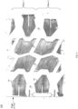
Fig. 3 ,tire 100 includes a plurality of shoulder blocks, where a second block type of the plurality of shoulder blocks is included. In the example, the plurality of second block types (e.g., second block type 302) include atread surface 303 that extends outward. As shown via the dashed lines, thetread surface 303 of thesecond block type 302 extends outward to the edge oftire 100. Referring at least to the example implementation ofFig. 4 , a footprint oftire 100 is shown to help show the differences between the tread surface of thefirst block type 300 recessed from the edge oftire 100, and the tread surface of thesecond block type 302 extends outward to the edge oftire 100. As noted above,first block type 300 may be recessed from the edge by, e.g., 5mm, and recessed from the tread surface by, e.g., 8mm. - In some implementations, the plurality of shoulder blocks may include an alternating pattern using the plurality of first block types (e.g., first block type 300) and the plurality of second block types (e.g., second block type 302). In some implementations, the alternating pattern may include, e.g.,
first block type 300,second block type 302,first block type 300,second block type 302, etc. It will be appreciated that other alternating patterns may also be used without departing from the scope of the invention. For example, the alternating pattern may includefirst block type 300,first block type 300,second block type 302,second block type 302,first block type 300,first block type 300, etc. As such, the example alternating pattern shown viaFig. 3 should be taken as example only and not to otherwise limiting the scope of the invention. In some implementations, the repeating pattern may providetire 100 more "bite" or grip into the mud or other soft surface, thus creating more lateral and longitudinal force to improve handling. - In some implementations, the tire may further comprise a plurality of lateral grooves of a plurality of center ribs. For example, and referring still to the example implementation of
Fig. 3 ,tire 100 may include a plurality of lateral grooves (e.g.,lateral groove 304 shown via dashed lines) of the plurality of center ribs. In some implementations, the width of the lateral grooves may range from, e.g., 25 to 30mm, however, it will be appreciated that other size ranges may be used without departing from the scope of the invention. In some implementations, a first portion of the plurality of lateral grooves may be staggered from a second portion of the plurality of lateral grooves. For example, as shown viaFig. 3 , each of thelateral grooves 304 is shown staggered (i.e., offset) from one another. Staggering the lateral grooves may provide resistance to air flow in the footprint, which may help with noise suppression. For example, one of the tire noise mechanism is a so-called air pumping effect. When the tire rotates and its surfaces comes into contact with the road surface, most of the air between the tire and the road surface may get pushed out, but the air in the tread grooves may become trapped and then compressed, creating the kind of 'whistling" noise. When the grooves are inline, it may be easier for the compressed air to travel, thus causing more noise. Staggered grooves may provide no direct path for noise travel, thus reducing noise. - In some implementations, one or more of the plurality of lateral grooves of the plurality of center ribs may be connected to one or more lateral grooves on the shoulder. For example, and referring still to the example implementation of
Fig. 3 , lateral groove 304 (of the center ribs) may be connected to another lateral groove (e.g.,lateral groove 306 shown via white dashed lines 307) on the shoulder oftire 100. - In some implementations, the one or more of the plurality of lateral grooves of the plurality of center ribs may be narrower than the one or more lateral grooves on the shoulder. For example, and referring still to the example implementation of
Fig. 3 , lateral groove 304 (of the center ribs) may be narrower than lateral groove 306 (on the shoulder) oftire 100. The narrowerlateral grooves 304 being connected with widerlateral grooves 306 may additionally / alternatively reduce the above-noted air pumping effect, as the wider shoulder grooves may provide "pressure" release for the trapped air. In some implementations, the ratio of narrowerlateral groove 304 to widerlateral groove 306 may be, e.g., 1:2, however, it will be appreciated that other ratios may be used onlateral groove 304 andlateral groove 306 without departing from the scope of the invention. - In some implementations, the one or more of the plurality of lateral grooves of the plurality of center ribs (e.g., lateral groove 304) may have an angle of 62 degrees, and the one or more lateral grooves on the shoulder (e.g., lateral groove 306) may have an angle of 72 degrees. It will be appreciated that other angles may be used on
lateral groove 304 andlateral groove 306 without departing from the scope of the invention. As such, the example angles of 62 and 72 degrees should be taken as example only and not to otherwise limit the scope of the invention. - The sidewall includes a 3-ply with 2 ply high turn-up construction. For example, and referring to the example implementation of
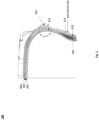
Fig. 5 ,tire 100 includes a lower sidewall, which includes a 3-ply with 2 ply high turn-up construction. This means that the tire carcass has a total of 3 plies, with 2 of the 3 plies being high turn-up. For example, when abody ply 501 is turned (wrapped around the bead 503) to the upper or middle sidewall area, it may be referred to as high turn-up construction. The 3-ply sidewall with the high turn-up construction may act as an extra layer on reinforcement to increase puncture resistance of the low sidewall area. In some implementations, three layers ofpolyester cord fabric 505 and two high strength layers ofsteel belts 507, and two layers ofnylon 509 in the tread may guard against rock and debris puncture to the tread area. In some implementations,tire 100 may include a plurality ofbeads 503 in abead filler 511, surrounded by five layers ofpolyester 513, and onechafer layer 515. - In some implementations, only two rows of the plurality of shoulder blocks may contact a bottom surface at maximum tire load of the tire. For example, and referring again to the example implementation of
Fig. 4 , assume that the maximum tire load oftire 100 is being applied (e.g., the maximum tire load specified in the T&RA manual and stamped on the tire sidewall, such as the example 35X12.5R20 (as illustrated inFigure 5 ) tire with the max load of 1450kg). In the example, only two rows (or substantially only two rows) of the plurality of shoulder blocks is making contact with the bottom surface. Thus, in the example, at the maximum tire load, at least two rows, but less than 3 full rows of the plurality of shoulder blocks is making contact with the bottom surface. Large tread blocks may provide stiff tread for enhanced off-road and all season performance. Large tread block may be quantified by a block's area and its relative size to tire-road contact area. Block surface area may vary with tire size, but using 35" outer diameter size as an sample, the surface area of a block may range from, e.g., 9500-14000 mm2. For all sizes, at maximum tire load there are two rows of tread blocks that are in contact with the road, in comparison other tires of similar application having 3 - 4 rows of tread blocks in contact with the road. - In some implementations,
tire 100 may have a ratio of rubber to void on the tread of, e.g., 5.4:4.6. This may allow for optimum balances for on-road and off-road (e.g., mud) performances. It will be appreciated that other ratios may be used without departing from the scope of the invention. - In some implementations,
tire 100 may be formulated using a variety of different materials for one or more of its sections (e.g., tread, sidewall, base rubber, bead rim cushion, belt, overlay, bodyply, buffer layer, inner liner, apex, bead, etc.). Table 600 shown inFig. 6 shows example materials and amounts of materials used for each of its section. It will be appreciated that various other materials and amounts may be used without departing from the scope of the invention. As such, the material in table 600 should be taken as example only and not to otherwise limit the scope of the invention. - In some implementations,
tire 100 may come in a variety of sizes with various specifications (e.g., tire size, load index, speed symbol, ply rating, outside diameter, section width, tread depth, load cap, etc.). Table 700 shown inFig. 7 shows example specifications that may be used for different tire sizes. It will be appreciated that various other sizes with differing specifications may be used without departing from the scope of the invention. As such, the sizes and specifications in table 700 should be taken as example only and not to otherwise limit the scope of the invention. - The terminology used herein is for the purpose of describing particular implementations only and is not intended to be limiting of the invention. As used herein, the singular forms "a", "an" and "the" are intended to include the plural forms as well, unless the context clearly indicates otherwise. As used herein, the language "at least one of A, B, and C" (and the like) should be interpreted as covering only A, only B, only C, or any combination of the three, unless the context clearly indicates otherwise. It will be further understood that the terms "comprises" and/or "comprising," when used in this specification, specify the presence of stated features, integers, elements, and/or components, but do not preclude the presence or addition of one or more other features, integers, elements, components, and/or groups thereof.
- The description of the present invention has been presented for purposes of illustration and description, but is not intended to be exhaustive or limited to the invention in the form disclosed. Many modifications, variations, substitutions, and any combinations thereof will be apparent to those of ordinary skill in the art without departing from the scope of the claims. The implementation(s) were chosen and described in order to explain the principles of the invention and the practical application, and to enable others of ordinary skill in the art to understand the invention for various implementation(s) with various modifications and/or any combinations of implementation(s) as are suited to the particular use contemplated.
- Having thus described the invention of the present application in detail and by reference to implementation(s) thereof, it will be apparent that modifications, variations, and any combinations of implementation(s) (including any modifications, variations, substitutions, and combinations thereof) are possible without departing from the scope of the invention defined in the appended claims.
Claims (12)
- A tire (100) comprising:a sidewall including an upper sidewall (102), wherein the upper sidewall includes a plurality of angled winged blocks (200) proximate an outer edge of the tire; anda plurality of shoulder blocks (106), wherein the plurality of shoulder blocks are at the outer edge of the tire on a shoulder (104), wherein the plurality of shoulder blocks includes a plurality of first block types (300), wherein the plurality of first block types includes a tread surface recessed from an edge of the tire, wherein the plurality of shoulder blocks includes a plurality of second block types (302), and wherein the plurality of second block types includes a tread surface that extends outward to the edge of the tire;characterized in that the plurality of angled winged blocks are extruded, angled winged blocks; andthe sidewall includes a 3-ply with 2 ply high turn-up construction.
- The tire (100) of claim 1 wherein the plurality of shoulder blocks (106) includes an alternating pattern using the plurality of first block types (300) and the plurality of second block types (302).
- The tire (100) of claim 1 further comprising a plurality of lateral grooves (304) of a plurality of center ribs.
- The tire (100) of claim 3 wherein a first portion of the plurality of lateral grooves (304) are staggered from a second portion of the plurality of lateral grooves (304).
- The tire (100) of claim 4 wherein one or more of the plurality of lateral grooves (304) of the plurality of center ribs are connected to one or more lateral grooves (306) on the shoulder.
- The tire (100) of claim 5 wherein the one or more of the plurality of lateral grooves (304) of the plurality of center ribs arc narrower than the one or more lateral grooves (306) on the shoulder.
- The tire (100) of claim 6 wherein the one or more of the plurality of lateral grooves (304) of the plurality of center ribs have an angle of 62 degrees, and wherein the one or more lateral grooves (306) on the shoulder have an angle of 72 degrees.
- The tire (100) of claim 1 wherein only two rows of the plurality of shoulder blocks (106) contact a bottom surface at maximum tire load of the tire.
- The tire (100) of claim 2 further comprising a plurality of lateral grooves (304) of a plurality of center ribs.
- The tire (100) of claim 9 wherein a first portion of the plurality of lateral grooves (304) are staggered from a second portion of the plurality of lateral grooves (304).
- The tire (100) of claim 9 wherein one or more of the plurality of lateral grooves (304) of the plurality of center ribs arc connected to one or more lateral grooves (306) on the shoulder.
- The tire (100) of claim 1 1 wherein the one or more of the plurality of lateral grooves (304) of the plurality of center ribs are narrower than the one or more lateral grooves (306) on the shoulder.
Priority Applications (1)
| Application Number | Priority Date | Filing Date | Title |
|---|---|---|---|
| RS20241175A RS66196B1 (en) | 2016-04-26 | 2017-04-26 | Tire with unique tread block and upper sidewall design |
Applications Claiming Priority (2)
| Application Number | Priority Date | Filing Date | Title |
|---|---|---|---|
| US201662327660P | 2016-04-26 | 2016-04-26 | |
| PCT/US2017/029578 WO2017189688A1 (en) | 2016-04-26 | 2017-04-26 | Tire with unique tread block and up sidewall designs |
Publications (4)
| Publication Number | Publication Date |
|---|---|
| EP3448698A1 EP3448698A1 (en) | 2019-03-06 |
| EP3448698A4 EP3448698A4 (en) | 2019-12-11 |
| EP3448698B1 true EP3448698B1 (en) | 2024-07-24 |
| EP3448698C0 EP3448698C0 (en) | 2024-07-24 |
Family
ID=60088369
Family Applications (1)
| Application Number | Title | Priority Date | Filing Date |
|---|---|---|---|
| EP17790322.6A Active EP3448698B1 (en) | 2016-04-26 | 2017-04-26 | Tire with unique tread block and upper sidewall design |
Country Status (9)
| Country | Link |
|---|---|
| US (1) | US20170305203A1 (en) |
| EP (1) | EP3448698B1 (en) |
| CN (1) | CN109689400A (en) |
| AU (1) | AU2017255556B2 (en) |
| ES (1) | ES2991245T3 (en) |
| MX (1) | MX2018013192A (en) |
| NZ (1) | NZ747566A (en) |
| RS (1) | RS66196B1 (en) |
| WO (1) | WO2017189688A1 (en) |
Families Citing this family (4)
| Publication number | Priority date | Publication date | Assignee | Title |
|---|---|---|---|---|
| JP2019104413A (en) | 2017-12-13 | 2019-06-27 | Toyo Tire株式会社 | Pneumatic tire |
| TWI669224B (en) * | 2018-06-05 | 2019-08-21 | 正新橡膠工業股份有限公司 | Tire pattern structure |
| JP6644272B1 (en) * | 2018-09-14 | 2020-02-12 | 横浜ゴム株式会社 | Pneumatic tire |
| JP7202175B2 (en) * | 2018-12-21 | 2023-01-11 | Toyo Tire株式会社 | pneumatic tire |
Citations (1)
| Publication number | Priority date | Publication date | Assignee | Title |
|---|---|---|---|---|
| US20090107600A1 (en) * | 2007-10-31 | 2009-04-30 | Lisa Marie Missik-Gaffney | Grip tire with added puncture protection |
Family Cites Families (14)
| Publication number | Priority date | Publication date | Assignee | Title |
|---|---|---|---|---|
| US5361815A (en) * | 1992-11-16 | 1994-11-08 | The Goodyear Tire & Rubber Company | Tread for a tire with blocks and ribs |
| ES2089690T3 (en) * | 1992-12-30 | 1996-10-01 | Michelin Rech Tech | TIRE ROLLER BELT COMPENSATING FOR THE RESIDUAL ALIGNMENT TORQUE. |
| US6213180B1 (en) * | 1997-03-26 | 2001-04-10 | Bridgestone Corporation | Pneumatic radial tire including beveled acute angle corner portions |
| US6189586B1 (en) * | 1998-10-15 | 2001-02-20 | Warren L. Guidry | Pneumatic rubber tire for on/off-road vehicles |
| US6920906B2 (en) * | 2001-08-31 | 2005-07-26 | Bridgestone/Firestone North American Tire, Llc | Pneumatic tire with sidewall projections |
| US6913053B2 (en) * | 2002-05-22 | 2005-07-05 | Bridgestone/Firestone North American Tire, Llc | Three ply layer turn-up pneumatic tire |
| US7874331B2 (en) * | 2007-03-02 | 2011-01-25 | The Goodyear Tire & Rubber Company | Pneumatic tire with tread having chamfer located in notch |
| US7784511B2 (en) * | 2007-03-02 | 2010-08-31 | The Goodyear Tire & Rubber Company | Pneumatic tire having extension blocks |
| US20090095397A1 (en) * | 2007-10-15 | 2009-04-16 | Robert Anthony Neubauer | Floating two-ply tire |
| FR2924376B1 (en) * | 2007-12-03 | 2009-11-20 | Michelin Soc Tech | DEVICE AND METHOD FOR PRODUCING A BEARING BAND |
| JP4980872B2 (en) * | 2007-12-20 | 2012-07-18 | 東洋ゴム工業株式会社 | Pneumatic tire |
| CN102991276A (en) * | 2011-09-09 | 2013-03-27 | 建大橡胶(中国)有限公司 | Special tyre for off-road vehicles |
| JP5698776B2 (en) * | 2013-02-14 | 2015-04-08 | 住友ゴム工業株式会社 | Heavy duty pneumatic tire |
| USD791681S1 (en) * | 2015-04-24 | 2017-07-11 | Shandong Hongsheng Rubber Co., Ltd. | Tire |
-
2017
- 2017-04-26 EP EP17790322.6A patent/EP3448698B1/en active Active
- 2017-04-26 WO PCT/US2017/029578 patent/WO2017189688A1/en not_active Ceased
- 2017-04-26 ES ES17790322T patent/ES2991245T3/en active Active
- 2017-04-26 NZ NZ747566A patent/NZ747566A/en unknown
- 2017-04-26 US US15/497,649 patent/US20170305203A1/en not_active Abandoned
- 2017-04-26 CN CN201780026284.3A patent/CN109689400A/en active Pending
- 2017-04-26 MX MX2018013192A patent/MX2018013192A/en unknown
- 2017-04-26 RS RS20241175A patent/RS66196B1/en unknown
- 2017-04-26 AU AU2017255556A patent/AU2017255556B2/en active Active
Patent Citations (1)
| Publication number | Priority date | Publication date | Assignee | Title |
|---|---|---|---|---|
| US20090107600A1 (en) * | 2007-10-31 | 2009-04-30 | Lisa Marie Missik-Gaffney | Grip tire with added puncture protection |
Also Published As
| Publication number | Publication date |
|---|---|
| EP3448698A4 (en) | 2019-12-11 |
| MX2018013192A (en) | 2019-07-04 |
| US20170305203A1 (en) | 2017-10-26 |
| NZ747566A (en) | 2020-06-26 |
| AU2017255556A1 (en) | 2018-11-15 |
| AU2017255556B2 (en) | 2020-03-05 |
| EP3448698A1 (en) | 2019-03-06 |
| CA3022111A1 (en) | 2017-11-02 |
| RS66196B1 (en) | 2024-12-31 |
| WO2017189688A1 (en) | 2017-11-02 |
| CN109689400A (en) | 2019-04-26 |
| ES2991245T3 (en) | 2024-12-03 |
| EP3448698C0 (en) | 2024-07-24 |
Similar Documents
| Publication | Publication Date | Title |
|---|---|---|
| CN104334372B (en) | pneumatic tire | |
| US8950452B2 (en) | Motorcycle tire for running on rough terrain | |
| AU2016213134B2 (en) | Pneumatic tire | |
| CN105980173B (en) | Pneumatic tire | |
| US8616253B2 (en) | Tyre for vehicle wheels | |
| JP5564224B2 (en) | Pneumatic tire | |
| CN109291739B (en) | Tyre for vehicle wheels | |
| JPH11291718A (en) | Pneumatic tire | |
| CN109955655B (en) | Pneumatic tires | |
| US20180043737A1 (en) | Pneumatic Tire | |
| CN107150557A (en) | Tyre for vehicle wheels | |
| CN103665450A (en) | Rubber composition for tread groove reinforcement | |
| CN108215667B (en) | Pneumatic tire | |
| CN105934355B (en) | Tire for motorcycle | |
| JP2012179964A (en) | Pneumatic tire | |
| CN105555549A (en) | Pneumatic tire | |
| WO2013150783A1 (en) | Pneumatic tire | |
| AU2017255556B2 (en) | Tire with unique tread block and up sidewall designs | |
| JP7502660B2 (en) | tire | |
| JP7172953B2 (en) | pneumatic tire | |
| US11318795B2 (en) | Pneumatic tire | |
| JP6766460B2 (en) | Pneumatic tires | |
| JP3377262B2 (en) | Pneumatic tires for motorcycles | |
| CA3022111C (en) | Tire with alternating shoulder blocks | |
| CN113508042B (en) | Tires for two-wheelers |
Legal Events
| Date | Code | Title | Description |
|---|---|---|---|
| STAA | Information on the status of an ep patent application or granted ep patent |
Free format text: STATUS: THE INTERNATIONAL PUBLICATION HAS BEEN MADE |
|
| PUAI | Public reference made under article 153(3) epc to a published international application that has entered the european phase |
Free format text: ORIGINAL CODE: 0009012 |
|
| STAA | Information on the status of an ep patent application or granted ep patent |
Free format text: STATUS: REQUEST FOR EXAMINATION WAS MADE |
|
| 17P | Request for examination filed |
Effective date: 20181123 |
|
| AK | Designated contracting states |
Kind code of ref document: A1 Designated state(s): AL AT BE BG CH CY CZ DE DK EE ES FI FR GB GR HR HU IE IS IT LI LT LU LV MC MK MT NL NO PL PT RO RS SE SI SK SM TR |
|
| AX | Request for extension of the european patent |
Extension state: BA ME |
|
| DAV | Request for validation of the european patent (deleted) | ||
| DAX | Request for extension of the european patent (deleted) | ||
| A4 | Supplementary search report drawn up and despatched |
Effective date: 20191108 |
|
| RIC1 | Information provided on ipc code assigned before grant |
Ipc: B60C 11/01 20060101ALN20191104BHEP Ipc: B60C 13/02 20060101ALN20191104BHEP Ipc: B60C 15/00 20060101ALN20191104BHEP Ipc: B60C 11/03 20060101AFI20191104BHEP Ipc: B60C 11/11 20060101ALI20191104BHEP |
|
| STAA | Information on the status of an ep patent application or granted ep patent |
Free format text: STATUS: EXAMINATION IS IN PROGRESS |
|
| 17Q | First examination report despatched |
Effective date: 20200702 |
|
| REG | Reference to a national code |
Free format text: PREVIOUS MAIN CLASS: B60C0011110000 Ref country code: DE Ref legal event code: R079 Ref document number: 602017083546 Country of ref document: DE Free format text: PREVIOUS MAIN CLASS: B60C0011110000 Ipc: B60C0011030000 |
|
| RIC1 | Information provided on ipc code assigned before grant |
Ipc: B60C 15/00 20060101ALN20230404BHEP Ipc: B60C 13/02 20060101ALN20230404BHEP Ipc: B60C 11/01 20060101ALN20230404BHEP Ipc: B60C 11/11 20060101ALI20230404BHEP Ipc: B60C 11/03 20060101AFI20230404BHEP |
|
| GRAP | Despatch of communication of intention to grant a patent |
Free format text: ORIGINAL CODE: EPIDOSNIGR1 |
|
| STAA | Information on the status of an ep patent application or granted ep patent |
Free format text: STATUS: GRANT OF PATENT IS INTENDED |
|
| RIC1 | Information provided on ipc code assigned before grant |
Ipc: B60C 15/00 20060101ALN20240109BHEP Ipc: B60C 13/02 20060101ALN20240109BHEP Ipc: B60C 11/01 20060101ALN20240109BHEP Ipc: B60C 11/11 20060101ALI20240109BHEP Ipc: B60C 11/03 20060101AFI20240109BHEP |
|
| RIC1 | Information provided on ipc code assigned before grant |
Ipc: B60C 11/11 20060101ALI20240119BHEP Ipc: B60C 11/03 20060101AFI20240119BHEP Ipc: B60C 15/00 20060101ALN20240119BHEP Ipc: B60C 13/02 20060101ALN20240119BHEP Ipc: B60C 11/01 20060101ALN20240119BHEP |
|
| INTG | Intention to grant announced |
Effective date: 20240212 |
|
| GRAS | Grant fee paid |
Free format text: ORIGINAL CODE: EPIDOSNIGR3 |
|
| GRAA | (expected) grant |
Free format text: ORIGINAL CODE: 0009210 |
|
| STAA | Information on the status of an ep patent application or granted ep patent |
Free format text: STATUS: THE PATENT HAS BEEN GRANTED |
|
| AK | Designated contracting states |
Kind code of ref document: B1 Designated state(s): AL AT BE BG CH CY CZ DE DK EE ES FI FR GB GR HR HU IE IS IT LI LT LU LV MC MK MT NL NO PL PT RO RS SE SI SK SM TR |
|
| REG | Reference to a national code |
Ref country code: GB Ref legal event code: FG4D |
|
| REG | Reference to a national code |
Ref country code: CH Ref legal event code: EP |
|
| REG | Reference to a national code |
Ref country code: IE Ref legal event code: FG4D Ref country code: DE Ref legal event code: R096 Ref document number: 602017083546 Country of ref document: DE |
|
| U01 | Request for unitary effect filed |
Effective date: 20240824 |
|
| U07 | Unitary effect registered |
Designated state(s): AT BE BG DE DK EE FI FR IT LT LU LV MT NL PT RO SE SI Effective date: 20241009 |
|
| REG | Reference to a national code |
Ref country code: ES Ref legal event code: FG2A Ref document number: 2991245 Country of ref document: ES Kind code of ref document: T3 Effective date: 20241203 |
|
| PG25 | Lapsed in a contracting state [announced via postgrant information from national office to epo] |
Ref country code: NO Free format text: LAPSE BECAUSE OF FAILURE TO SUBMIT A TRANSLATION OF THE DESCRIPTION OR TO PAY THE FEE WITHIN THE PRESCRIBED TIME-LIMIT Effective date: 20241024 |
|
| PG25 | Lapsed in a contracting state [announced via postgrant information from national office to epo] |
Ref country code: GR Free format text: LAPSE BECAUSE OF FAILURE TO SUBMIT A TRANSLATION OF THE DESCRIPTION OR TO PAY THE FEE WITHIN THE PRESCRIBED TIME-LIMIT Effective date: 20241025 Ref country code: PL Free format text: LAPSE BECAUSE OF FAILURE TO SUBMIT A TRANSLATION OF THE DESCRIPTION OR TO PAY THE FEE WITHIN THE PRESCRIBED TIME-LIMIT Effective date: 20240724 |
|
| PG25 | Lapsed in a contracting state [announced via postgrant information from national office to epo] |
Ref country code: HR Free format text: LAPSE BECAUSE OF FAILURE TO SUBMIT A TRANSLATION OF THE DESCRIPTION OR TO PAY THE FEE WITHIN THE PRESCRIBED TIME-LIMIT Effective date: 20240724 |
|
| PG25 | Lapsed in a contracting state [announced via postgrant information from national office to epo] |
Ref country code: PL Free format text: LAPSE BECAUSE OF FAILURE TO SUBMIT A TRANSLATION OF THE DESCRIPTION OR TO PAY THE FEE WITHIN THE PRESCRIBED TIME-LIMIT Effective date: 20240724 Ref country code: NO Free format text: LAPSE BECAUSE OF FAILURE TO SUBMIT A TRANSLATION OF THE DESCRIPTION OR TO PAY THE FEE WITHIN THE PRESCRIBED TIME-LIMIT Effective date: 20241024 Ref country code: HR Free format text: LAPSE BECAUSE OF FAILURE TO SUBMIT A TRANSLATION OF THE DESCRIPTION OR TO PAY THE FEE WITHIN THE PRESCRIBED TIME-LIMIT Effective date: 20240724 Ref country code: GR Free format text: LAPSE BECAUSE OF FAILURE TO SUBMIT A TRANSLATION OF THE DESCRIPTION OR TO PAY THE FEE WITHIN THE PRESCRIBED TIME-LIMIT Effective date: 20241025 |
|
| PG25 | Lapsed in a contracting state [announced via postgrant information from national office to epo] |
Ref country code: SM Free format text: LAPSE BECAUSE OF FAILURE TO SUBMIT A TRANSLATION OF THE DESCRIPTION OR TO PAY THE FEE WITHIN THE PRESCRIBED TIME-LIMIT Effective date: 20240724 |
|
| PG25 | Lapsed in a contracting state [announced via postgrant information from national office to epo] |
Ref country code: CZ Free format text: LAPSE BECAUSE OF FAILURE TO SUBMIT A TRANSLATION OF THE DESCRIPTION OR TO PAY THE FEE WITHIN THE PRESCRIBED TIME-LIMIT Effective date: 20240724 |
|
| PG25 | Lapsed in a contracting state [announced via postgrant information from national office to epo] |
Ref country code: SK Free format text: LAPSE BECAUSE OF FAILURE TO SUBMIT A TRANSLATION OF THE DESCRIPTION OR TO PAY THE FEE WITHIN THE PRESCRIBED TIME-LIMIT Effective date: 20240724 |
|
| PLBE | No opposition filed within time limit |
Free format text: ORIGINAL CODE: 0009261 |
|
| STAA | Information on the status of an ep patent application or granted ep patent |
Free format text: STATUS: NO OPPOSITION FILED WITHIN TIME LIMIT |
|
| U20 | Renewal fee for the european patent with unitary effect paid |
Year of fee payment: 9 Effective date: 20250425 |
|
| 26N | No opposition filed |
Effective date: 20250425 |
|
| PGFP | Annual fee paid to national office [announced via postgrant information from national office to epo] |
Ref country code: GB Payment date: 20250429 Year of fee payment: 9 Ref country code: ES Payment date: 20250530 Year of fee payment: 9 |
|
| PGFP | Annual fee paid to national office [announced via postgrant information from national office to epo] |
Ref country code: IS Payment date: 20250425 Year of fee payment: 9 Ref country code: RS Payment date: 20250423 Year of fee payment: 9 |
|
| REG | Reference to a national code |
Ref country code: CH Ref legal event code: H13 Free format text: ST27 STATUS EVENT CODE: U-0-0-H10-H13 (AS PROVIDED BY THE NATIONAL OFFICE) Effective date: 20251125 |
|
| PG25 | Lapsed in a contracting state [announced via postgrant information from national office to epo] |
Ref country code: MC Free format text: LAPSE BECAUSE OF FAILURE TO SUBMIT A TRANSLATION OF THE DESCRIPTION OR TO PAY THE FEE WITHIN THE PRESCRIBED TIME-LIMIT Effective date: 20240724 |
|
| PG25 | Lapsed in a contracting state [announced via postgrant information from national office to epo] |
Ref country code: CH Free format text: LAPSE BECAUSE OF NON-PAYMENT OF DUE FEES Effective date: 20250430 |
|
| PG25 | Lapsed in a contracting state [announced via postgrant information from national office to epo] |
Ref country code: IE Free format text: LAPSE BECAUSE OF NON-PAYMENT OF DUE FEES Effective date: 20250426 |