EP3448286B1 - An intraosseous device - Google Patents
An intraosseous device Download PDFInfo
- Publication number
- EP3448286B1 EP3448286B1 EP17720759.4A EP17720759A EP3448286B1 EP 3448286 B1 EP3448286 B1 EP 3448286B1 EP 17720759 A EP17720759 A EP 17720759A EP 3448286 B1 EP3448286 B1 EP 3448286B1
- Authority
- EP
- European Patent Office
- Prior art keywords
- handle
- formations
- hub
- stylet
- cannula
- Prior art date
- Legal status (The legal status is an assumption and is not a legal conclusion. Google has not performed a legal analysis and makes no representation as to the accuracy of the status listed.)
- Active
Links
Images






Classifications
-
- A—HUMAN NECESSITIES
- A61—MEDICAL OR VETERINARY SCIENCE; HYGIENE
- A61B—DIAGNOSIS; SURGERY; IDENTIFICATION
- A61B17/00—Surgical instruments, devices or methods
- A61B17/34—Trocars; Puncturing needles
- A61B17/3472—Trocars; Puncturing needles for bones, e.g. intraosseus injections
-
- A—HUMAN NECESSITIES
- A61—MEDICAL OR VETERINARY SCIENCE; HYGIENE
- A61B—DIAGNOSIS; SURGERY; IDENTIFICATION
- A61B17/00—Surgical instruments, devices or methods
- A61B17/16—Instruments for performing osteoclasis; Drills or chisels for bones; Trepans
- A61B17/164—Instruments for performing osteoclasis; Drills or chisels for bones; Trepans intramedullary
-
- A—HUMAN NECESSITIES
- A61—MEDICAL OR VETERINARY SCIENCE; HYGIENE
- A61B—DIAGNOSIS; SURGERY; IDENTIFICATION
- A61B17/00—Surgical instruments, devices or methods
- A61B17/34—Trocars; Puncturing needles
- A61B17/3415—Trocars; Puncturing needles for introducing tubes or catheters, e.g. gastrostomy tubes, drain catheters
-
- A—HUMAN NECESSITIES
- A61—MEDICAL OR VETERINARY SCIENCE; HYGIENE
- A61B—DIAGNOSIS; SURGERY; IDENTIFICATION
- A61B17/00—Surgical instruments, devices or methods
- A61B17/34—Trocars; Puncturing needles
- A61B17/3417—Details of tips or shafts, e.g. grooves, expandable, bendable; Multiple coaxial sliding cannulas, e.g. for dilating
- A61B17/3421—Cannulas
Definitions
- handle formations and the hub formations comprise interlock formations.
- the handle formations 41 and the hub formations 42 only interlock when the tip of the stylet and the tip of the cannula are aligned for optimum bone penetration.
- the stabiliser 60 has mounting features for engaging the stabiliser with the intraosseous device.
- the mounting features include an inturned ledge 70 which in use defines a receiver which engages with the outer periphery of the hub flange 50.
- the stabiliser can be closed on the hub one handed by the user. This is made possible by the combination of the hinge 63 and the locking mechanism 64, 65. Finally the ribbed wings 66, 67 are flexible, allowing for conforming to the patients skin surface at the cannula insertion site. Once secured with tape this allows for a robust stabilisation of the cannula.
Landscapes
- Health & Medical Sciences (AREA)
- Surgery (AREA)
- Life Sciences & Earth Sciences (AREA)
- Molecular Biology (AREA)
- General Health & Medical Sciences (AREA)
- Veterinary Medicine (AREA)
- Engineering & Computer Science (AREA)
- Biomedical Technology (AREA)
- Heart & Thoracic Surgery (AREA)
- Medical Informatics (AREA)
- Public Health (AREA)
- Animal Behavior & Ethology (AREA)
- Nuclear Medicine, Radiotherapy & Molecular Imaging (AREA)
- Pathology (AREA)
- Orthopedic Medicine & Surgery (AREA)
- Dentistry (AREA)
- Oral & Maxillofacial Surgery (AREA)
- Gastroenterology & Hepatology (AREA)
- Surgical Instruments (AREA)
- Infusion, Injection, And Reservoir Apparatuses (AREA)
Description
- There are currently several different intraosseous devices commercially available and, in general, these are stainless steel needles with central removable stylets/trocars that reduce plugging risk during insertion. Studies and case reports on these products have shown that manual needles can be easily used in young paediatric patients. However, it has been seen that it is difficult to insert these in adults (S.M. Blumberg, 2008) (L. Phillips, 2010).
-
US4,487,209 describes a biopsy needle. -
EP1925261A describes a hand-held instrument that accesses interior body regions. -
US6,217,561 describes a medication injection device and method, -
WO2014/134438 describes a direct pressure mediated intra-bone delivery system for cellular therapeutics. -
WO2005/072625 describes a manual intraosseous device. -
WO2008/054894 describes apparatus and method to communicate fluids and/or support intraosseous devices. - The failure mode of current intraosseous devices is primarily a failure to easily penetrate adult bone. There is therefore a need for an intraosseous device that can readily penetrate adult bone.
- According to the invention there is provided an intraosseous device as defined in
claim 1. Preferred embodiments are defined in the dependent claims. - In one case the handle formations and the hub formations comprise interlock formations.
- The handle formations and the hub formations may be engagable only in a set number of engagement configurations of the handle relative to the hub. In one case the set number is one. In another case the set number is two and the engagement configuration are at 180° to each other.
- In one embodiment the formations comprise ribs and corresponding recesses.
- The formations may be of generally polygonal shape.
- In one case the formations comprise at least one dovetail formation of the handle which in the engaged configuration is engaged with a corresponding dovetail formation of the hub.
- The handle may comprise a pair of dovetail formations which are diametrically opposed. In one case the handle comprises two pairs of dovetail formations.
- The handle formations and the hub formations may be engagable only in a set number of engagement configurations of the handle relative to the hub. The set number may be one. In one case the set number is two and the engagement configuration are at 180° to each other.
- The formations may comprise at least one dovetail formation of the handle which in the engaged configuration is engaged with a corresponding dovetail formation of the hub. The handle may comprise a pair of dovetail formations which are diametrically opposed. The handle may comprise two pairs of dovetail formations.
- In some cases the handle is configured for manual operation and may comprise manual grip features. In other cases the handle is configured for connection to a powered driver.
- In one case the handle is configured for connection to a powered driver for torque transmission.
- In some embodiments the handle comprises drive formations for interengagement with corresponding formations of a powered driver.
- In some cases the handle has a central formation for engaging with a corresponding central formation of a powered driver.
- Also provided is a system comprising an intraosseous device of the invention and a powered driver which is adapted for releasable connection to the handle.
- The powered driver may comprise a drive shaft, and the drive shaft has one end for connecting with the handle of the device. The powered driver may comprise a motor for providing rotary motion to the drive shaft. In one case the powered driver comprises a gear assembly rotatably attached to the motor. The powered driver may further comprise a power supply and electrical circuitry for providing power to the motor. The powered device may have at least one electronic switch. The switch may be an on/off switch which activates and de-activates the powered device. A switch may be used to increase or decrease the speed of rotation of the drive shaft. In some cases activation of a switch causes power to be supplied of either polarity so the motor can rotate in either a clockwise or anti-clockwise direction.
- In one case the bent portion of the stylet extends at an angle of from 10° to 30° to the longitudinal axis of the main body of the stylet. The bent portion of the stylet may extend at an angle of about 20° to the longitudinal axis of the stylet.
- In one embodiment the bent portion of the stylet has a roughened surface.
- In one case the flare at the hub end of the cannula is a split flare.
- In one embodiment the hub end of the cannula has a roughened surface.
- The hub may comprise a circumferential flange part. The flange part may have cut-away regions to facilitate finger engagement with the hub.
- In one embodiment the hub comprises a luer connector which is exposed on removal of the handle body.
- The handle may comprise a handle body to which the handle end of the stylet is mounted and a handle cover which is mounted to the handle body. The handle body may comprise a socket to receive a corresponding spigot of the handle cover.
- In one case the cover has a ledge extending around the periphery thereof and a depending wall and wherein the handle body has a corresponding recess to receive the depending wall of the handle cover.
- In one embodiment both the handle body and the handle cover are generally rectilinear in transverse cross section with rounded corners. The handle body and the handle cover may have manual grip features.
- In all embodiments the cannula may have a series of markings which may extend around the cannula. The markings are used to indicate to a user the length that the cannula has penetrated into bone. At distances such as every 5mm along the length of the cannula the markings may be differentiated, for example made thicker, for ease of monitoring by the user.
- In one embodiment the intraosseous device further comprises a removable protective tube for the stylet and cannula.
- Also provided is an intraosseous system comprising an intraosseous device and a stabiliser for stabilising the device, in situ. Also provided is a stabiliser for use in stabilising an intraosseous device. The intraosseous device may be a device according to the various embodiments described herein.
- In one embodiment the stabiliser comprises mounting features for engaging the stabiliser with the intraosseous device. The stabiliser may comprise side wings for mounting to the skin of a patient.
- In one case the stabiliser comprises a pair of half cylindrical elements which are hinged together on one side and which have a locking system for interlocking the parts on an opposite side.
- A side wing may extend outwardly from each of the half cylindrical elements.
- In another embodiment the stabiliser comprises cushioning to engage with the hub at different locations and/or orientations of the hub.
- The invention will be more clearly understood from the following description thereof, given by way of example only, with reference to the accompanying drawings, in which:
-
Fig. 1 is a perspective view of a manual intraosseous device according to the invention including a protective tube; -
Fig. 2 is an exploded view of the device ofFig. 1 ; -
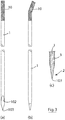
Fig. 3(a), (b) and (c) are a series of images showing a stylet part of the device; -
Figs. 4(a), (b) and (c) are views of a cannula part of the device; -
Fig. 5 is a cut-away view illustrating the mounting of the stylet in a handle body of the device; -
Fig. 6 is a perspective view of a handle body of the device; -
Fig. 7 is a cut-away view of the handle body; -
Fig. 8 is a perspective view of a head part forming a handle cover of the device; -
Fig. 9 is a perspective view of a hub part of the device; -
Fig. 10 is a cut-away view of the hub part; -
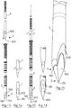
Fig. 11 is an exploded view illustrating the stylet being inserted into the cannula; -
Fig. 12 are views of the stylet tip; -
Fig. 13 is a view illustrating the stylet inserted into the cannula; -
Figs. 14 and 15 illustrate the engagement of the tip of the stylet and the tip of the cannula; -
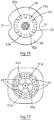
Fig. 16 is a top plan view of the hub showing hub engagement formations; -
Fig. 17 is an underneath plan view of the handle showing handle engagement formations; -
Fig. 18 is an exploded view illustrating the engagement of the hub formations with the handle formations; -
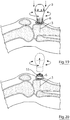
Fig. 19 is a diagram of the device being inserted into the bone of a patient; -
Fig. 20 is a view of the intraosseous device with the handle removed; -
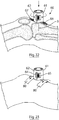
Figs. 21(a) and 21(b) are perspective views of a stabilising anchor; -
Figs. 22 and 23 are perspective views of the stabilising anchor in use with the intraosseous device; and -
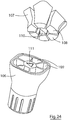
Fig. 24 is a perspective view of portion of another intraosseous device. - Referring to the drawings there is illustrated an intraosseous device according to the invention which comprises a
stylet 1 with apointed needle end 2 for penetrating tissue and bone and acannula 3 through which thestylet 1 extends. Thecannula 3 has abone penetrating end 4. The upper end of thestylet 1 is mounted to ahandle body 5 and the upper end of thecannula 3 is mounted to ahub 6 which is releasably mountable to thehandle body 5. The device also includes ahandle cover 7. A removableprotective tube 8 may be provided for thestylet 1 andcannula 3 before use. - The
stylet 1 has abent portion 10 at the handle end and thehandle body 5 has areceiver 11 for receiving and retaining thebent portion 10 of thestylet 1. Thebent portion 10 has a roughened surface, which may be generated by grit blasting, for example, for enhanced engagement with an adhesive which further fixes thebent portion 10 in thehandle body 5 in a manner than prevents rotation of thestylet 1 relative to thehandle body 5 when manual torque is applied to penetrate tissue and bone, in use. - The
bent portion 10 of the stylet extends at an angle of from 10° to 30°, about 20° to the longitudinal axis of the stylet. We have found that this angle optimally achieves optimum engagement in the handle without sacrificing the strength and torqueability of the stylet. - The
cannula 3 has an outwardly extendingflare 20 at the hub end. In this case the flare is a split flare which is engaged in acorresponding seat 21 in thehub 6. The flared hub end also has a roughenedsurface 22, which may be generated by grit blasting, for example, for enhanced engagement with an adhesive which further fixes the hub end of thecannula 3 in thehub 6 in a manner that prevents rotation of thecannula 3 relative to thehub 6 when manual torque is applied, in use. - The
bend 10 at the handle end of thestylet 1 and engages in the receiver of the handle. This ensures that thestylet 1 cannot rotate independently of thehandle 5, regardless of the level of manual torque applied. The hub end of thecannula 3 is flared and this was found to be able to withstand up to 10 times more torque than a straight sand-blasted surface. The result of the reinforcement of thestylet 1 and thecannula 3 is an exceptionally strong and robust manual intraosseous device. - The cannula has a series of
markings 25 that are used to indicate to a user the length that the cannula has penetrated into bone. These graduated markings allow for better localisation at hospital and monitoring of the penetration depth. Every 5 mm along the length of the cannula the circumferential markings are thicker to make it easier again for the user to quickly examine the depth of penetration. This is important to the user as if the cannula penetration depth has moved, it may indicate that the cannula has moved out of the bone. - The
handle body 5 has asocket 30 to receive a correspondingspigot 31 of thehandle cover 7. Thehandle cover 7 also has a ledge 35 extending around the periphery thereof and a dependingwall 36 which engages with acorresponding recess 37 in thehandle body 5. Thehandle body 5 is reinforced withvarious ribs 38. Similarly, thehandle cover 7 also has reinforcingribs 39. - The
handle body 5 and thehandle cover 7 are generally rectilinear in transverse cross section with rounded corners for ease of gripping by the user somewhat like the handle of a screwdriver for ease of gripping and application of torque by a user. Thehandle parts - The hub end of the
handle body 5 has arecess 40 and a series of circumferentially spaced-apartformations 41 that engage withcorresponding recesses 42 at a handle end of thehub 6. The interlocking engagement between the handle and hub formations / recesses 41, 42 are highly effective for torque transmission. - The
hub 6 has acircumferential flange 50 which widens the region of contact between the device and the patient. Theflange 50 has cut-awayregions 51 to facilitate gripping engagement of a user's fingers with thehub 6. Thehub 6 also has aluer connector 55 for engagement with a luer of another device such as an intraosseous extension set that connects to the fluids to be administered. - Referring to
Figs. 11 to 15 , thestylet 1 andcannula 3 are shown in more detail. Theend 4 of the cannula has two bevellededges 100 which define two cuttingtips 101. Thebone retracting end 1 of thestylet 3 also has bevellededges 102 which define asingle cutting tip 103. In the correct alignment of the stylet end and the cannula end, the cuttingtip 103 of the stylet projects beyond the cuttingtips 101 of the cannula and the bevellededges 100 of the cannula and the bevellededges 102 of the stylet are aligned and flush with each other for optimum penetration and cutting efficiency. - The engagement of the
handle 7 andhub 6 are shown in more detail inFigs. 16 to 18 . The hub end of thehandle body 5 has arecess 40 for receiving thehub 6 and a series of circumferentially spaced-apartformations 41 that engage withcorresponding hub formations 42 at a handle end of thehub 6. In use, the handle is rotated and thehandle formations 41 engage with thehub formations 42. This results in an interlocking engagement of thehandle 7 andhub 5 and allows for effective torque transmission which is particularly advantageous as the device is manually operated. - The
handle formations 41 and thehub formations 42 only interlock when the tip of the stylet and the tip of the cannula are aligned for optimum bone penetration. - Importantly, the engagement between the hub and the handle allows for both clockwise and anticlockwise twisting. This is important to ensure that the stylet and the cannula are aligned for optimum bone penetration and also to facilitate the natural twist tendencies of both left and right handed users. The engagement system also provides for significant torque strength which is necessary to achieve manual penetration of bone.
- The
handle formations 41 and thehub formations 42 are engagable only in a set number of engagement configurations of the handle relative to the hub. In some cases the set number may be one. In the embodiment illustrated the set number is two and the engagement configuration are at 180° to each other. - In the aligned configuration, the
handle 5 is movable downwardly for interlocking thehandle formations 41 with thehub formations 42. - The plurality of
hub formations 42 comprise formations of differing shapes and the plurality ofhandle formations 41 comprise formations of differing shapes. In the engaging configuration, handleformations 41 which are of the same shape asformations 42 of the hub are aligned. - In some cases the formations comprise ribs and corresponding recesses which may be of generally polygonal shape.
- The formations in this case comprise at least one
dovetail formation 41a of the handle which in the engaged configuration is engaged with acorresponding dovetail formation 42a of the hub. In one embodiment the handle comprises a pair ofdovetail formations 41a which are diametrically opposed and the handle comprises two pairs ofdovetail formations 41a of matching size and shape to thehub dovetail formations 42a. The formations are shaped for ease of effective interlocking engagement - In use, when access is required to the bone marrow the
protective tube 8 is removed which exposes thepointed end 103 of thestylet 1. The user grasps the device firmly and a torqueing action is used to force the stylet and the following cannula tip to penetrate bone. Thehandle part 5 andstylet 1 are then removed leaving theluer 55 on thehub 6 exposed for connection to an extension set that connects to fluids to be administered. Fluids are administered through thecannula 3. - Referring to
Figs. 19 and 20 , there is illustrated the intraosseous device of the invention inserted into a patient. The rotation in both an anti-clockwise and a clockwise direction are illustrated by arrows. - Referring to
Figs. 21 to 23 there is illustrated a stabilisinganchor 60 which is used to anchor theintraosseous device 1 in use, for example to the patient. Thestabiliser 60 comprises a pair of halfcylindrical elements strip 64 on oneelement 61 and areceiver 65 on theother element 62 is provided on the other side of theelements Side wings elements wings wings adhesive tape 80 may be used over the wings for securing to the patients skin as illustrated inFig. 23 - The
stabiliser 60 has mounting features for engaging the stabiliser with the intraosseous device. The mounting features include aninturned ledge 70 which in use defines a receiver which engages with the outer periphery of thehub flange 50. - The
inner surfaces elements - Many patients where intraosseous access is administered require quick transport. Such transport can result in dislodgement of the intraosseous device. The stabiliser helps to protect the device from dislodgement so that uninterrupted administration of fluids can occur. Additionally it is designed to fit and secure the cannula by gripping the hub at any height. This allows for multiple depth securements as the penetration depth may be different from patient to patient. It is also unlikely that the user will insert the cannula in such a way that the
hub 50 is at exactly 90 degrees to the skin surface. The cushioning allows for stabilisation even if the cannula is not inserted at a 90 degree angle. - Additionally, the stabiliser can be closed on the hub one handed by the user. This is made possible by the combination of the
hinge 63 and thelocking mechanism ribbed wings - The stabiliser can be fitted to the device hub and closed around it and locked. Once in place around the hub
medical tape 80 can be placed over the wings to secure these to the patient's skin. This stabilises the device for continued fluid administration or transport.Figs. 22 and 23 illustrate the use of the stabiliser of the invention in more detail. There is illustrated a stabilisinganchor 60 which is used to anchor theintraosseous device 1 in use, for example to the patient. Thestabiliser 60 comprises a pair of halfcylindrical elements side wings elements Fig. 23 , it can be seen thatadhesive strips 80 are used to secureside wings - The handle may be gripped by a user and/or may be driven by any suitable accessory or tool such as a powered driver. For example, the handle may be releasably engagable with a powered tool, either directly or by using a suitable adaptor that engage with the handle and the powered driver. For example, the handle may have formations such as those described above which are engagable with a powered driver. In this way the device can be manually operated and/or assisted by a power driver. In the case of the device of
Figs. 1 to 20 , thelid part 7 of the handle may be removed and the powered tool engaged with the upper end of the handle formations. - Another example of such a device can be seen in
Fig. 24 . In this example, the device is illustrated in association with a powered driving tool. The device comprises a hub and ahandle 106, which are releasably mounted with a stylet mounted to the handle and a cannula mounted to the hub, as in previous embodiments. In this case thehandle 106 is illustrated being releasably engaging with a powered driver for torque transmission. - The
handle 106 has formations adapted to receive portions of apowered driver end 107, so that thehandle 106 andpowered driver 107 inter-engage. - The
powered driver end 107 has circumferentially spaced-apartformations 108 for engaging withcorresponding recesses 109 of thehandle 106. In addition, thedriver 107 has acentral formation 110 for engaging with acentral recess 111 in thehandle 106. This configuration of inter-engaging formations has the advantage of providing central, as well as radially spaced apart engagement, resulting in a secure connection and significant torque strength. - The
handle 106 may have rounded corners and may have additional external recesses and/or ribs to aid gripping, so that in use thehandle 106 can be held in place for the reception of thepower driver formations - Upon engagement of the formations of the
handle 106 and the formations of thedriver connector 107, the power driver is releasably connected to thehandle 106. - The power driver comprises a drive shaft, a motor for providing the rotary motion to the drive shaft, a power supply and electronic circuitry. The motor provides rotary motion to the drive shaft, which has one end, 107, for connecting with the
handle 106. This rotary motion may be provided via a gear assembly, so that the frequency of rotation of the drive shaft can be increased or decreased. - It is envisaged that a set of switches may also be used to control the use of the power device. For example, there may be a switch for turning on and off the power of the device and another for increasing or decreasing the speed of rotation of the drive shaft. There may also be another switch for anti-clockwise and clockwise rotation of the drive shaft.
- Upon activation of the power device the motor provides a rotary motion to the drive shaft, which rotates the handle of the device and transmits torque to the stylet and the cannula for bone penetration of the patient.
- The device can be inserted into bone at any desired location including a humeral head, a proximal tibia, and a distal tibia. Typical procedures using the intraosseous device are as follows.
-
- 1. Prepare the intended insertion site with antiseptic solution.
- 2. Hold the handle 57 in the palm of the hand and place thumb and index fingers in the hub fingers slots.
- 3. Puncture the skin at the insertion site and push the
needle 1 through subcutaneous tissue until bone contact. - 4. Begin bone insertion with the
needle 1 at a 90° angle at the surface using a steady twisting/rotation action along with gentle inward pressure. - 5. As the
needle tip 103 enters the bone, continue advancing the cannula and stylet with a steady clockwise and anticlockwise rotation/twisting through the cortex of the bone until a slight give is felt (i.e. loss of resistance). The device is designed to cut using this twisting/rotation and only gentle pressure against the bone is needed. - 6. When loss of resistance is felt, the
needle trocar stylet 1 is removed by stabilising thecannula hub 3 and withdrawing thehandle 5 with the stylet mounted to it. The stylet is disposed of in sharps containment. No handle twisting is required to disengage. Thehandle 5 can be pulled upwardly for removal. - 7. The provided connection extension set is primed with saline and connected to the
Leur lock connection 55 on thecannula hub 6. - 8. The position of the intramedullary needle is confirmed by aspirating a small visual quantity of bone marrow and then the cannula is flushed with an appropriate volume (e.g. 10ml in adults) of 0.9% saline.
- 9. After flushing, medication/fluids can be administered.
- 10. The
cannula hub 6 is stabilised by using the stabilisation device.- a) The stabilisation device is opened by unclasping the locking mechanism (64, 65).
- b) The stabilisation device is placed around the
cannula hub 6 with the wings (66, 67) based against the skin (for tibia, the stabilisation device is placed with the wings in line with the long axis of the bone). - c) The stabilisation device is then closed until a click is heard as a result of engagement of the
locking mechanism Tape 80 is then applied acrosswings
- The stabilisation device, if it has been applied, is removed first. Then, the cannula hub in a clockwise and anticlockwise motion as the cannula is pulled straight out from the bone. If achieving grip on the needle cannula hub is difficult then a Leur syringe may be connected directly to the
Leur lock connection 55 and gently twisted in a clockwise direction as the syringe/needle hub is pulled out. Once removed, thecannula 3 is placed in an appropriate sharps container.
Claims (15)
- An intraosseous device comprising:-a handle (5, 7);a hub (6) which is releasably mounted to the handle;a stylet (1) having an end mounted to the handle; anda cannula (3) having an end mounted to the hub,the handle end of the stylet (1) having a bend and the handle having a receiver (11) for the bent portion (10) of the stylet (1) for non-rotatably fixing the stylet (1) to the handle;the hub end of the cannula (3) having an outwardly extending flare (20) for non-rotatably fixing the cannula (3) to the hub (6);the handle and the hub (6) having interengagable formations (41, 42) for torque transmission to the stylet (1) and the cannula (3) for bone penetration on either clockwise or anticlockwise rotation of the device,the formations (41, 42) comprising a plurality of circumferentially spaced-apart handle formations (41) that are engagable with a plurality of corresponding formations (42) of the hub,the plurality of hub formations (42) comprising formations of differing shapes andthe plurality of handle formations (41) comprising formations of differing shapes wherein, in the engaged configuration, handle formations (41) of the same shape as formations (42) of the hub are aligned,the handle being rotatable relative to the hub (6) from a disengaged configuration in which the handle formations (41) are not aligned with the hub formations (42) to an aligned configuration in which the handle formations (41) are aligned with the hub formations (42),wherein, in the aligned configuration, the handle is movable axially for interlocking the handle formations (41) with the hub formations (42), andwherein, in the interlocked configuration, a tip (103) of the stylet (1) extends from a distal end of the cannula (3) and a bevelled edge (102) of the stylet (1) is aligned with a bevelled edge (101) of the cannula (3).
- An intraosseous device as claimed in claim 1 wherein the handle formations (41) and the hub formations (42) are engagable only in a set number of engagement configurations of the handle relative to the hub.
- An intraosseous device as claimed in claim 2 wherein the set number is one or wherein the set number is two and the engagement configurations are at 180° to each other.
- An intraosseous device as claimed in any of claims 1 to 3 wherein the formations (41, 42) comprise ribs and corresponding recesses.
- An intraosseous device as claimed in any of claims 1 to 4 wherein the formations (41, 42) are of generally polygonal shape.
- An intraosseous device as claimed in any of claims 1 to 5 wherein the formations comprise at least one dovetail formation (41) of the handle which in the engaged configuration is engaged with a corresponding dovetail formation (42) of the hub, in one case the handle comprises a pair of dovetail formations (41) which are diametrically opposed, in one case the handle comprises two pairs of dovetail formations (41).
- An intraosseous device as claimed in any of claims 1 to 6 wherein the bent portion (10) of the stylet (1) extends at an angle of from 10° to 30° to the longitudinal axis of the main body of the stylet, in one case the bent portion (10) of the stylet (1) extends at an angle of about 20° to the longitudinal axis of the stylet.
- An intraosseous device as claimed in any of claims 1 to 7 wherein the bent portion (10) of the stylet (1) has a roughened surface.
- An intraosseous device as claimed in any of claims 1 to 8 wherein the flare (20) at the hub end of the cannula (3) is a split flare.
- An intraosseous device as claimed in any of claims 1 to 9 wherein the hub end of the cannula (3) has a roughened surface.
- An intraosseous device as claimed in any of claims 1 to 10 wherein the hub comprises a circumferential flange part (50), in one case the flange part (50) has cut-away regions (51) to facilitate finger engagement with the hub.
- An intraosseous device as claimed in any of claims 1 to 11 wherein the handle is configured for connection to a powered driver (107) for torque transmission,
the handle may comprise formations (109) for interengagement with corresponding formations (108) of a powered driver, in one case the handle formations comprise a plurality of circumferentially spaced-apart formations (109) that are engageable with a plurality of corresponding formations (108) of a powered driver, in one case the handle has a central formation (111) for engaging with a corresponding central formation (110) of a powered driver. - A system comprising an intraosseous device as claimed in any of claims 1 to 12 and an accessory such as a powered driver which is adapted for releasable connection to the handle.
- An intraosseous system comprising a device as claimed in any of claims 1 to 12 and/or a system as claimed in claim 13 and a stabiliser (60) for stabilising the device, in situ.
- An intraosseous system as claimed in claim 14 wherein the stabiliser (60) comprises mounting features (70) for engaging the stabiliser with the intraosseous device, in one case the stabiliser (60) comprises side wings (66, 67) for mounting to the skin of a patient, in one case the stabiliser (60) comprises a pair of half cylindrical elements (71, 72) which are hinged together (63) on one side and which have a locking system (64, 65) for interlocking the parts on an opposite side, a side wing (66, 67) may extend outwardly from each of the half cylindrical elements (71, 72), in one case the stabiliser (60) comprises cushioning to engage with the hub at different locations and/or orientations of the hub.
Priority Applications (1)
| Application Number | Priority Date | Filing Date | Title |
|---|---|---|---|
| EP20193246.4A EP3777729A1 (en) | 2016-04-28 | 2017-04-26 | An intraosseous device |
Applications Claiming Priority (4)
| Application Number | Priority Date | Filing Date | Title |
|---|---|---|---|
| EP16167438 | 2016-04-28 | ||
| EP17157674 | 2017-02-23 | ||
| EP17160940 | 2017-03-14 | ||
| PCT/EP2017/059931 WO2017186794A1 (en) | 2016-04-28 | 2017-04-26 | An intraosseous device |
Related Child Applications (2)
| Application Number | Title | Priority Date | Filing Date |
|---|---|---|---|
| EP20193246.4A Division-Into EP3777729A1 (en) | 2016-04-28 | 2017-04-26 | An intraosseous device |
| EP20193246.4A Division EP3777729A1 (en) | 2016-04-28 | 2017-04-26 | An intraosseous device |
Publications (2)
| Publication Number | Publication Date |
|---|---|
| EP3448286A1 EP3448286A1 (en) | 2019-03-06 |
| EP3448286B1 true EP3448286B1 (en) | 2020-10-28 |
Family
ID=58664686
Family Applications (2)
| Application Number | Title | Priority Date | Filing Date |
|---|---|---|---|
| EP17720759.4A Active EP3448286B1 (en) | 2016-04-28 | 2017-04-26 | An intraosseous device |
| EP20193246.4A Withdrawn EP3777729A1 (en) | 2016-04-28 | 2017-04-26 | An intraosseous device |
Family Applications After (1)
| Application Number | Title | Priority Date | Filing Date |
|---|---|---|---|
| EP20193246.4A Withdrawn EP3777729A1 (en) | 2016-04-28 | 2017-04-26 | An intraosseous device |
Country Status (6)
| Country | Link |
|---|---|
| US (2) | US10433871B2 (en) |
| EP (2) | EP3448286B1 (en) |
| CA (1) | CA3022148A1 (en) |
| ES (1) | ES2843824T3 (en) |
| WO (1) | WO2017186794A1 (en) |
| ZA (1) | ZA201807131B (en) |
Families Citing this family (11)
| Publication number | Priority date | Publication date | Assignee | Title |
|---|---|---|---|---|
| WO2017136273A1 (en) | 2016-02-01 | 2017-08-10 | RegenMed Systems, Inc. | Cannula for tissue disruption |
| US10980522B2 (en) | 2016-10-18 | 2021-04-20 | Piper Access, Llc | Intraosseous access devices, systems, and methods |
| US10265481B2 (en) * | 2016-11-02 | 2019-04-23 | Abul Bashar Mohammad Anwarul Islam | Intramarrow injection/infusion and aspiration needle and method |
| EP3568083B1 (en) | 2017-03-07 | 2021-04-28 | Piper Access, LLC. | Safety shields for elongated instruments and related systems |
| JP7169984B2 (en) | 2017-03-10 | 2022-11-11 | パイパー・アクセス、エルエルシー | Fastening device, fastening system, and fastening method |
| US20200054347A1 (en) * | 2017-09-09 | 2020-02-20 | Billie Coppedge | Foldable, stowable intraosseous device with automatic power generation when opened |
| WO2019051343A1 (en) * | 2017-09-09 | 2019-03-14 | June Medical Ip, Llc | Passive safety intraosseous device |
| ES2953372T3 (en) | 2018-02-20 | 2023-11-10 | Piper Access Llc | Drilling devices and related methods |
| US11642472B2 (en) * | 2019-08-27 | 2023-05-09 | Black Tie Medical Inc. | Hub for coupling a cannula with a transfer device |
| KR102360346B1 (en) * | 2019-12-31 | 2022-02-10 | (주)엘앤케이바이오메드 | Medical Needle Apparatus |
| US20250261967A1 (en) * | 2022-04-11 | 2025-08-21 | Relievant Medsystems, Inc. | Controlled bone access and operator feedback features |
Family Cites Families (14)
| Publication number | Priority date | Publication date | Assignee | Title |
|---|---|---|---|---|
| US4487209A (en) | 1981-03-16 | 1984-12-11 | Creative Research And Manufacturing Inc. | Biopsy needle |
| US4838282A (en) | 1987-02-26 | 1989-06-13 | Manan Manufacturing Co., Inc. | Bone biopsy needle assembly |
| US5257632A (en) * | 1992-09-09 | 1993-11-02 | Symbiosis Corporation | Coaxial bone marrow biopsy coring and aspirating needle assembly and method of use thereof |
| US5372583A (en) * | 1992-11-25 | 1994-12-13 | Cardiopulmonary Specialities, Inc. | Bone marrow infuser and method of use |
| US6217561B1 (en) | 1995-06-06 | 2001-04-17 | David Gibbs | Medication injection device and method |
| DE60032887T2 (en) | 1999-03-19 | 2007-10-25 | Cervi, Paul Laurence | BIOPSY NEEDLE |
| US6575919B1 (en) | 1999-10-19 | 2003-06-10 | Kyphon Inc. | Hand-held instruments that access interior body regions |
| ATE478606T1 (en) | 2004-01-26 | 2010-09-15 | Vidacare Corp | MANUAL INTEROSSARY DEVICE |
| US8974410B2 (en) * | 2006-10-30 | 2015-03-10 | Vidacare LLC | Apparatus and methods to communicate fluids and/or support intraosseous devices |
| US9682180B2 (en) | 2009-11-15 | 2017-06-20 | Thoratec Corporation | Attachment system, device and method |
| IN2009DE02581A (en) * | 2009-12-11 | 2015-07-03 | Stanford India Biodesign | |
| US9839740B2 (en) * | 2010-02-02 | 2017-12-12 | Teleflex Medical Devices S.À R.L | Intraosseous-needle stabilizer and methods |
| BR112014000796A2 (en) | 2011-07-11 | 2017-03-01 | Vidacare Corp | sternal locators and associated systems and methods |
| WO2014134438A1 (en) | 2013-03-01 | 2014-09-04 | The United States Of America, As Represented By The Secretary, Department Of Health & Human Services | Direct pressure-mediated intra-bone delivery system for cellular therapeutics |
-
2017
- 2017-04-26 EP EP17720759.4A patent/EP3448286B1/en active Active
- 2017-04-26 EP EP20193246.4A patent/EP3777729A1/en not_active Withdrawn
- 2017-04-26 CA CA3022148A patent/CA3022148A1/en not_active Abandoned
- 2017-04-26 WO PCT/EP2017/059931 patent/WO2017186794A1/en not_active Ceased
- 2017-04-26 ES ES17720759T patent/ES2843824T3/en active Active
- 2017-04-26 US US15/497,770 patent/US10433871B2/en active Active
-
2018
- 2018-10-25 ZA ZA2018/07131A patent/ZA201807131B/en unknown
-
2019
- 2019-08-27 US US16/552,635 patent/US20190380744A1/en not_active Abandoned
Non-Patent Citations (1)
| Title |
|---|
| None * |
Also Published As
| Publication number | Publication date |
|---|---|
| ZA201807131B (en) | 2019-07-31 |
| ES2843824T3 (en) | 2021-07-20 |
| US10433871B2 (en) | 2019-10-08 |
| US20190380744A1 (en) | 2019-12-19 |
| US20170311981A1 (en) | 2017-11-02 |
| EP3448286A1 (en) | 2019-03-06 |
| WO2017186794A1 (en) | 2017-11-02 |
| CA3022148A1 (en) | 2017-11-02 |
| EP3777729A1 (en) | 2021-02-17 |
Similar Documents
| Publication | Publication Date | Title |
|---|---|---|
| US10433871B2 (en) | Intraosseous device | |
| EP4031017B1 (en) | Step needle for intraosseous access device | |
| CN101541370B (en) | Intraosseous device and methods for accessing bone marrow in the sternum and other target areas | |
| US6221029B1 (en) | Universal biopsy system | |
| US8246627B2 (en) | Cement delivery device for introducing cement into tissue, the device having a cavity creator | |
| US6019776A (en) | Precision depth guided instruments for use in vertebroplasty | |
| US4838282A (en) | Bone biopsy needle assembly | |
| CN101474088B (en) | Manual interosseous device | |
| EP3125985B1 (en) | Devices and methods for installation and removal of a needle tip of a needle | |
| CN113473926B (en) | Intraosseous access device and method of accessing bone marrow | |
| CN103458812A (en) | Suprapubic safety cannula | |
| EP3821833B1 (en) | Device for intraosseous needle removal | |
| CN108420464B (en) | Biopsy sampling device | |
| US12150627B2 (en) | Bone biopsy device and related methods | |
| EP3167828A1 (en) | Apparatus for use in conjunction with an intraosseous device | |
| GB2551257A (en) | An intraosseous device | |
| IE20170090A1 (en) | An intraosseous device | |
| IE87040B1 (en) | An intraosseous device | |
| EP3986299B1 (en) | Intraosseous access device and locator assembly | |
| HK1176261A (en) | Manual interosseous device |
Legal Events
| Date | Code | Title | Description |
|---|---|---|---|
| STAA | Information on the status of an ep patent application or granted ep patent |
Free format text: STATUS: UNKNOWN |
|
| STAA | Information on the status of an ep patent application or granted ep patent |
Free format text: STATUS: THE INTERNATIONAL PUBLICATION HAS BEEN MADE |
|
| PUAI | Public reference made under article 153(3) epc to a published international application that has entered the european phase |
Free format text: ORIGINAL CODE: 0009012 |
|
| STAA | Information on the status of an ep patent application or granted ep patent |
Free format text: STATUS: REQUEST FOR EXAMINATION WAS MADE |
|
| 17P | Request for examination filed |
Effective date: 20181009 |
|
| AK | Designated contracting states |
Kind code of ref document: A1 Designated state(s): AL AT BE BG CH CY CZ DE DK EE ES FI FR GB GR HR HU IE IS IT LI LT LU LV MC MK MT NL NO PL PT RO RS SE SI SK SM TR |
|
| AX | Request for extension of the european patent |
Extension state: BA ME |
|
| DAV | Request for validation of the european patent (deleted) | ||
| DAX | Request for extension of the european patent (deleted) | ||
| RAP1 | Party data changed (applicant data changed or rights of an application transferred) |
Owner name: PROMETHEUS MEDICAL TECHNOLOGIES LIMITED |
|
| GRAP | Despatch of communication of intention to grant a patent |
Free format text: ORIGINAL CODE: EPIDOSNIGR1 |
|
| STAA | Information on the status of an ep patent application or granted ep patent |
Free format text: STATUS: GRANT OF PATENT IS INTENDED |
|
| INTG | Intention to grant announced |
Effective date: 20200519 |
|
| GRAS | Grant fee paid |
Free format text: ORIGINAL CODE: EPIDOSNIGR3 |
|
| GRAA | (expected) grant |
Free format text: ORIGINAL CODE: 0009210 |
|
| STAA | Information on the status of an ep patent application or granted ep patent |
Free format text: STATUS: THE PATENT HAS BEEN GRANTED |
|
| AK | Designated contracting states |
Kind code of ref document: B1 Designated state(s): AL AT BE BG CH CY CZ DE DK EE ES FI FR GB GR HR HU IE IS IT LI LT LU LV MC MK MT NL NO PL PT RO RS SE SI SK SM TR |
|
| REG | Reference to a national code |
Ref country code: GB Ref legal event code: FG4D |
|
| REG | Reference to a national code |
Ref country code: CH Ref legal event code: EP |
|
| REG | Reference to a national code |
Ref country code: AT Ref legal event code: REF Ref document number: 1327397 Country of ref document: AT Kind code of ref document: T Effective date: 20201115 |
|
| REG | Reference to a national code |
Ref country code: DE Ref legal event code: R096 Ref document number: 602017026324 Country of ref document: DE |
|
| REG | Reference to a national code |
Ref country code: IE Ref legal event code: FG4D |
|
| REG | Reference to a national code |
Ref country code: DE Ref legal event code: R082 Ref document number: 602017026324 Country of ref document: DE Representative=s name: HL KEMPNER PATENTANWAELTE, SOLICITORS (ENGLAND, DE Ref country code: DE Ref legal event code: R082 Ref document number: 602017026324 Country of ref document: DE Representative=s name: HL KEMPNER PATENTANWALT, RECHTSANWALT, SOLICIT, DE Ref country code: DE Ref legal event code: R082 Ref document number: 602017026324 Country of ref document: DE Representative=s name: HL KEMPNER PARTG MBB, DE |
|
| REG | Reference to a national code |
Ref country code: AT Ref legal event code: MK05 Ref document number: 1327397 Country of ref document: AT Kind code of ref document: T Effective date: 20201028 |
|
| REG | Reference to a national code |
Ref country code: NL Ref legal event code: MP Effective date: 20201028 |
|
| PG25 | Lapsed in a contracting state [announced via postgrant information from national office to epo] |
Ref country code: GR Free format text: LAPSE BECAUSE OF FAILURE TO SUBMIT A TRANSLATION OF THE DESCRIPTION OR TO PAY THE FEE WITHIN THE PRESCRIBED TIME-LIMIT Effective date: 20210129 Ref country code: FI Free format text: LAPSE BECAUSE OF FAILURE TO SUBMIT A TRANSLATION OF THE DESCRIPTION OR TO PAY THE FEE WITHIN THE PRESCRIBED TIME-LIMIT Effective date: 20201028 Ref country code: NO Free format text: LAPSE BECAUSE OF FAILURE TO SUBMIT A TRANSLATION OF THE DESCRIPTION OR TO PAY THE FEE WITHIN THE PRESCRIBED TIME-LIMIT Effective date: 20210128 Ref country code: RS Free format text: LAPSE BECAUSE OF FAILURE TO SUBMIT A TRANSLATION OF THE DESCRIPTION OR TO PAY THE FEE WITHIN THE PRESCRIBED TIME-LIMIT Effective date: 20201028 Ref country code: PT Free format text: LAPSE BECAUSE OF FAILURE TO SUBMIT A TRANSLATION OF THE DESCRIPTION OR TO PAY THE FEE WITHIN THE PRESCRIBED TIME-LIMIT Effective date: 20210301 |
|
| REG | Reference to a national code |
Ref country code: LT Ref legal event code: MG4D |
|
| PG25 | Lapsed in a contracting state [announced via postgrant information from national office to epo] |
Ref country code: PL Free format text: LAPSE BECAUSE OF FAILURE TO SUBMIT A TRANSLATION OF THE DESCRIPTION OR TO PAY THE FEE WITHIN THE PRESCRIBED TIME-LIMIT Effective date: 20201028 Ref country code: LV Free format text: LAPSE BECAUSE OF FAILURE TO SUBMIT A TRANSLATION OF THE DESCRIPTION OR TO PAY THE FEE WITHIN THE PRESCRIBED TIME-LIMIT Effective date: 20201028 Ref country code: IS Free format text: LAPSE BECAUSE OF FAILURE TO SUBMIT A TRANSLATION OF THE DESCRIPTION OR TO PAY THE FEE WITHIN THE PRESCRIBED TIME-LIMIT Effective date: 20210228 Ref country code: BG Free format text: LAPSE BECAUSE OF FAILURE TO SUBMIT A TRANSLATION OF THE DESCRIPTION OR TO PAY THE FEE WITHIN THE PRESCRIBED TIME-LIMIT Effective date: 20210128 Ref country code: AT Free format text: LAPSE BECAUSE OF FAILURE TO SUBMIT A TRANSLATION OF THE DESCRIPTION OR TO PAY THE FEE WITHIN THE PRESCRIBED TIME-LIMIT Effective date: 20201028 Ref country code: SE Free format text: LAPSE BECAUSE OF FAILURE TO SUBMIT A TRANSLATION OF THE DESCRIPTION OR TO PAY THE FEE WITHIN THE PRESCRIBED TIME-LIMIT Effective date: 20201028 |
|
| PG25 | Lapsed in a contracting state [announced via postgrant information from national office to epo] |
Ref country code: HR Free format text: LAPSE BECAUSE OF FAILURE TO SUBMIT A TRANSLATION OF THE DESCRIPTION OR TO PAY THE FEE WITHIN THE PRESCRIBED TIME-LIMIT Effective date: 20201028 Ref country code: NL Free format text: LAPSE BECAUSE OF FAILURE TO SUBMIT A TRANSLATION OF THE DESCRIPTION OR TO PAY THE FEE WITHIN THE PRESCRIBED TIME-LIMIT Effective date: 20201028 |
|
| REG | Reference to a national code |
Ref country code: ES Ref legal event code: FG2A Ref document number: 2843824 Country of ref document: ES Kind code of ref document: T3 Effective date: 20210720 |
|
| REG | Reference to a national code |
Ref country code: DE Ref legal event code: R097 Ref document number: 602017026324 Country of ref document: DE |
|
| PG25 | Lapsed in a contracting state [announced via postgrant information from national office to epo] |
Ref country code: EE Free format text: LAPSE BECAUSE OF FAILURE TO SUBMIT A TRANSLATION OF THE DESCRIPTION OR TO PAY THE FEE WITHIN THE PRESCRIBED TIME-LIMIT Effective date: 20201028 Ref country code: CZ Free format text: LAPSE BECAUSE OF FAILURE TO SUBMIT A TRANSLATION OF THE DESCRIPTION OR TO PAY THE FEE WITHIN THE PRESCRIBED TIME-LIMIT Effective date: 20201028 Ref country code: LT Free format text: LAPSE BECAUSE OF FAILURE TO SUBMIT A TRANSLATION OF THE DESCRIPTION OR TO PAY THE FEE WITHIN THE PRESCRIBED TIME-LIMIT Effective date: 20201028 Ref country code: SM Free format text: LAPSE BECAUSE OF FAILURE TO SUBMIT A TRANSLATION OF THE DESCRIPTION OR TO PAY THE FEE WITHIN THE PRESCRIBED TIME-LIMIT Effective date: 20201028 Ref country code: RO Free format text: LAPSE BECAUSE OF FAILURE TO SUBMIT A TRANSLATION OF THE DESCRIPTION OR TO PAY THE FEE WITHIN THE PRESCRIBED TIME-LIMIT Effective date: 20201028 Ref country code: SK Free format text: LAPSE BECAUSE OF FAILURE TO SUBMIT A TRANSLATION OF THE DESCRIPTION OR TO PAY THE FEE WITHIN THE PRESCRIBED TIME-LIMIT Effective date: 20201028 |
|
| PG25 | Lapsed in a contracting state [announced via postgrant information from national office to epo] |
Ref country code: DK Free format text: LAPSE BECAUSE OF FAILURE TO SUBMIT A TRANSLATION OF THE DESCRIPTION OR TO PAY THE FEE WITHIN THE PRESCRIBED TIME-LIMIT Effective date: 20201028 |
|
| PLBE | No opposition filed within time limit |
Free format text: ORIGINAL CODE: 0009261 |
|
| STAA | Information on the status of an ep patent application or granted ep patent |
Free format text: STATUS: NO OPPOSITION FILED WITHIN TIME LIMIT |
|
| 26N | No opposition filed |
Effective date: 20210729 |
|
| PG25 | Lapsed in a contracting state [announced via postgrant information from national office to epo] |
Ref country code: AL Free format text: LAPSE BECAUSE OF FAILURE TO SUBMIT A TRANSLATION OF THE DESCRIPTION OR TO PAY THE FEE WITHIN THE PRESCRIBED TIME-LIMIT Effective date: 20201028 |
|
| PG25 | Lapsed in a contracting state [announced via postgrant information from national office to epo] |
Ref country code: SI Free format text: LAPSE BECAUSE OF FAILURE TO SUBMIT A TRANSLATION OF THE DESCRIPTION OR TO PAY THE FEE WITHIN THE PRESCRIBED TIME-LIMIT Effective date: 20201028 Ref country code: MC Free format text: LAPSE BECAUSE OF FAILURE TO SUBMIT A TRANSLATION OF THE DESCRIPTION OR TO PAY THE FEE WITHIN THE PRESCRIBED TIME-LIMIT Effective date: 20201028 |
|
| PG25 | Lapsed in a contracting state [announced via postgrant information from national office to epo] |
Ref country code: LU Free format text: LAPSE BECAUSE OF NON-PAYMENT OF DUE FEES Effective date: 20210426 |
|
| REG | Reference to a national code |
Ref country code: BE Ref legal event code: MM Effective date: 20210430 |
|
| PG25 | Lapsed in a contracting state [announced via postgrant information from national office to epo] |
Ref country code: CH Free format text: LAPSE BECAUSE OF NON-PAYMENT OF DUE FEES Effective date: 20210430 Ref country code: LI Free format text: LAPSE BECAUSE OF NON-PAYMENT OF DUE FEES Effective date: 20210430 |
|
| PG25 | Lapsed in a contracting state [announced via postgrant information from national office to epo] |
Ref country code: IE Free format text: LAPSE BECAUSE OF NON-PAYMENT OF DUE FEES Effective date: 20210426 |
|
| PG25 | Lapsed in a contracting state [announced via postgrant information from national office to epo] |
Ref country code: IS Free format text: LAPSE BECAUSE OF FAILURE TO SUBMIT A TRANSLATION OF THE DESCRIPTION OR TO PAY THE FEE WITHIN THE PRESCRIBED TIME-LIMIT Effective date: 20210228 |
|
| PG25 | Lapsed in a contracting state [announced via postgrant information from national office to epo] |
Ref country code: BE Free format text: LAPSE BECAUSE OF NON-PAYMENT OF DUE FEES Effective date: 20210430 |
|
| PG25 | Lapsed in a contracting state [announced via postgrant information from national office to epo] |
Ref country code: CY Free format text: LAPSE BECAUSE OF FAILURE TO SUBMIT A TRANSLATION OF THE DESCRIPTION OR TO PAY THE FEE WITHIN THE PRESCRIBED TIME-LIMIT Effective date: 20201028 |
|
| PG25 | Lapsed in a contracting state [announced via postgrant information from national office to epo] |
Ref country code: HU Free format text: LAPSE BECAUSE OF FAILURE TO SUBMIT A TRANSLATION OF THE DESCRIPTION OR TO PAY THE FEE WITHIN THE PRESCRIBED TIME-LIMIT; INVALID AB INITIO Effective date: 20170426 |
|
| PG25 | Lapsed in a contracting state [announced via postgrant information from national office to epo] |
Ref country code: MK Free format text: LAPSE BECAUSE OF FAILURE TO SUBMIT A TRANSLATION OF THE DESCRIPTION OR TO PAY THE FEE WITHIN THE PRESCRIBED TIME-LIMIT Effective date: 20201028 |
|
| PGFP | Annual fee paid to national office [announced via postgrant information from national office to epo] |
Ref country code: IT Payment date: 20240419 Year of fee payment: 8 |
|
| PG25 | Lapsed in a contracting state [announced via postgrant information from national office to epo] |
Ref country code: MT Free format text: LAPSE BECAUSE OF FAILURE TO SUBMIT A TRANSLATION OF THE DESCRIPTION OR TO PAY THE FEE WITHIN THE PRESCRIBED TIME-LIMIT Effective date: 20201028 |
|
| PGFP | Annual fee paid to national office [announced via postgrant information from national office to epo] |
Ref country code: DE Payment date: 20250422 Year of fee payment: 9 |
|
| PGFP | Annual fee paid to national office [announced via postgrant information from national office to epo] |
Ref country code: ES Payment date: 20250507 Year of fee payment: 9 |
|
| PG25 | Lapsed in a contracting state [announced via postgrant information from national office to epo] |
Ref country code: TR Free format text: LAPSE BECAUSE OF FAILURE TO SUBMIT A TRANSLATION OF THE DESCRIPTION OR TO PAY THE FEE WITHIN THE PRESCRIBED TIME-LIMIT Effective date: 20201028 |
|
| PGFP | Annual fee paid to national office [announced via postgrant information from national office to epo] |
Ref country code: GB Payment date: 20260327 Year of fee payment: 10 |
|
| PG25 | Lapsed in a contracting state [announced via postgrant information from national office to epo] |
Ref country code: IT Free format text: LAPSE BECAUSE OF NON-PAYMENT OF DUE FEES Effective date: 20250426 |
|
| PGFP | Annual fee paid to national office [announced via postgrant information from national office to epo] |
Ref country code: FR Payment date: 20260320 Year of fee payment: 10 |