EP3447933B1 - Signal decoding method, apparatus and device - Google Patents
Signal decoding method, apparatus and device Download PDFInfo
- Publication number
- EP3447933B1 EP3447933B1 EP16909181.6A EP16909181A EP3447933B1 EP 3447933 B1 EP3447933 B1 EP 3447933B1 EP 16909181 A EP16909181 A EP 16909181A EP 3447933 B1 EP3447933 B1 EP 3447933B1
- Authority
- EP
- European Patent Office
- Prior art keywords
- signal
- coefficient
- equalization
- antenna
- timeslot
- Prior art date
- Legal status (The legal status is an assumption and is not a legal conclusion. Google has not performed a legal analysis and makes no representation as to the accuracy of the status listed.)
- Active
Links
Images


Classifications
-
- H—ELECTRICITY
- H04—ELECTRIC COMMUNICATION TECHNIQUE
- H04L—TRANSMISSION OF DIGITAL INFORMATION, e.g. TELEGRAPHIC COMMUNICATION
- H04L1/00—Arrangements for detecting or preventing errors in the information received
- H04L1/02—Arrangements for detecting or preventing errors in the information received by diversity reception
- H04L1/06—Arrangements for detecting or preventing errors in the information received by diversity reception using space diversity
- H04L1/0618—Space-time coding
- H04L1/0631—Receiver arrangements
-
- H—ELECTRICITY
- H04—ELECTRIC COMMUNICATION TECHNIQUE
- H04B—TRANSMISSION
- H04B7/00—Radio transmission systems, i.e. using radiation field
- H04B7/02—Diversity systems; Multi-antenna system, i.e. transmission or reception using multiple antennas
- H04B7/04—Diversity systems; Multi-antenna system, i.e. transmission or reception using multiple antennas using two or more spaced independent antennas
- H04B7/06—Diversity systems; Multi-antenna system, i.e. transmission or reception using multiple antennas using two or more spaced independent antennas at the transmitting station
- H04B7/0613—Diversity systems; Multi-antenna system, i.e. transmission or reception using multiple antennas using two or more spaced independent antennas at the transmitting station using simultaneous transmission
- H04B7/0667—Diversity systems; Multi-antenna system, i.e. transmission or reception using multiple antennas using two or more spaced independent antennas at the transmitting station using simultaneous transmission of delayed versions of same signal
-
- H—ELECTRICITY
- H04—ELECTRIC COMMUNICATION TECHNIQUE
- H04B—TRANSMISSION
- H04B7/00—Radio transmission systems, i.e. using radiation field
- H04B7/02—Diversity systems; Multi-antenna system, i.e. transmission or reception using multiple antennas
- H04B7/04—Diversity systems; Multi-antenna system, i.e. transmission or reception using multiple antennas using two or more spaced independent antennas
- H04B7/08—Diversity systems; Multi-antenna system, i.e. transmission or reception using multiple antennas using two or more spaced independent antennas at the receiving station
- H04B7/0891—Space-time diversity
-
- H—ELECTRICITY
- H04—ELECTRIC COMMUNICATION TECHNIQUE
- H04B—TRANSMISSION
- H04B7/00—Radio transmission systems, i.e. using radiation field
- H04B7/02—Diversity systems; Multi-antenna system, i.e. transmission or reception using multiple antennas
- H04B7/04—Diversity systems; Multi-antenna system, i.e. transmission or reception using multiple antennas using two or more spaced independent antennas
- H04B7/0413—MIMO systems
Definitions
- the present invention relates to the communications field, and in particular, to a signal decoding method, apparatus, and device.
- MIMO Multiple-Input Multiple-Output
- the MIMO technology means that a plurality of antennas are used at both a transmit end and a receive end of signals, and signals are transmitted and received by using the plurality of antennas at the transmit end and the receive end, so as to improve communication quality.
- a space-time coding technology emerges, to be specific, signal coding is performed in two dimensions: spatial domain and time domain, so that spatial diversity of a plurality of antennas is used in space to increase a system gain.
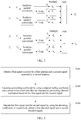
- FIG. 1 is an architectural diagram of an Alamouti space-time coding scheme.
- a signal transmit end has two antennas: a first antenna and a second antenna
- a signal receive end also has two antennas: a third antenna and a fourth antenna.
- Two different signals are obtained after serial-to-parallel conversion is performed on a signal s , and are a transmit signal s 1 and a transmit signal s 2 .
- the third antenna transmits the signal s 1
- the fourth antenna transmits the signal s 2
- the third antenna transmits a signal - s 2 *
- the fourth antenna transmits a signal s 1 *
- the first antenna receives a signal y 1
- the second antenna receives a signal y 2
- the first antenna receives a signal y 1 ′
- the second antenna receives a signal y 2 ′ .
- a phase noise means that a phase of an output signal randomly changes due to various noises at the transmit end of a signal.
- a longer wavelength and a lower frequency of a radio wave lead to a lower phase noise; otherwise, a shorter wavelength and a higher frequency of a radio wave lead to a higher phase noise.
- the Alamouti coding scheme is mainly pertinent to a radio wave with a relatively long wavelength and a relatively low frequency, for example, a long wave (with a wavelength of 1 km to 10 km and a frequency range of 30 KHz to 300 KHz) and a medium wave (with a wavelength range of 100 m to 1000 m and a frequency range of 300 KHz to 3000 KHz).
- the decoded signal ⁇ 1 obtained by the signal receive end through decoding is related only to the transmit signal s 1 and is unrelated to the transmit signal s 2 .
- the decoded signal ⁇ 2 obtained through decoding is related only to the transmit signal s 2 and is unrelated to the transmit signal s 2 .
- a decoding result is good.
- a phase noise is usually high for a radio wave with a relatively short wavelength and a relatively high frequency, for example, a microwave (with a wavelength range of 0.1 mm to 10 dm and a frequency range of 3000 MHz to 3000 GHz), a phase noise is usually high.
- the decoded signal ⁇ 1 obtained by the signal receive end through decoding is related to both the transmit signal s 1 and the transmit signal s 2 , to be specific, the transmit signal s 2 causes interference to the transmit signal s 1 .
- the decoded signal ⁇ 2 is related to both the transmit signal s 2 and the transmit signal s 1 , to be specific, the transmit signal s 1 causes interference to the transmit signal s 2 .
- a decoding result is relatively poor. Therefore, there is an urgent need for a method that can be applied to decode a radio wave with a relatively short wavelength and a relatively high frequency, to improve decoding performance.
- US 2007/0098092 A1 describes a technique for generating common phase error (CPE) estimates in a multicarrier receiver.
- the CPE estimates are generated for each channel between two or more transmit antennas and the multicarrier receiver.
- embodiments of the present invention provide a signal decoding method, apparatus, and device, so that a good decoding result can be obtained even if phase noises exist at a signal transmit end and a signal receive end in a 2 ⁇ 2 MIMO system.
- An embodiment of the present invention provides a signal decoding method, where the method is applied to a MIMO system, the MIMO system includes a signal transmit end and a signal receive end, the signal receive end includes a first antenna and a second antenna, and the signal transmit end includes a third antenna and a fourth antenna; and the method includes:
- the first group of equalization coefficients include a first equalization coefficient, a second equalization coefficient, a third equalization coefficient, and a fourth equalization coefficient; and the filtering the first group of four signals by using the first group of equalization coefficients to obtain a third signal and a fourth signal includes:
- the first equalization coefficient W 11 1 h 11
- the second equalization coefficient W 12 1 h 12 ⁇
- the third equalization coefficient W 13 1 h 21
- the fourth equalization coefficient W 14 1 h 22 ⁇
- h 11 is a channel fading coefficient from the third antenna to the first antenna
- h 12 ⁇ is a conjugate of h 12
- h 12 is a channel fading coefficient from the fourth antenna to the first antenna
- h 21 is a channel fading coefficient from the third antenna to the second antenna
- h 22 ⁇ is a conjugate of h 22
- h 22 is a channel fading coefficient from the fourth antenna to the second antenna.
- the second group of equalization coefficients include a fifth equalization coefficient, a sixth equalization coefficient, a seventh equalization coefficient, and an eighth equalization coefficient; and the filtering the second group of four signals by using the second group of equalization coefficients to obtain a fifth signal and a sixth signal includes:
- the fifth equalization coefficient W 21 1 h 12
- the sixth equalization coefficient W 22 ⁇ 1 h 11 ⁇
- the seventh equalization coefficient W 23 1 h 22
- the eighth equalization coefficient W 24 ⁇ 1 h 21 ⁇
- h 12 is a channel fading coefficient from the fourth antenna to the first antenna
- h 11 ⁇ is a conjugate of h 11
- h 11 is a channel fading coefficient from the third antenna to the first antenna
- h 22 is a channel fading coefficient from the fourth antenna to the second antenna
- h 21 ⁇ is a conjugate of h 21
- h 21 is a channel fading coefficient from the third antenna to the second antenna.
- the calculating the decoding coefficient by using the phase noise coefficient obtained by performing channel estimation on a signal obtained after equalization processing includes:
- the first group of decoding coefficients include a first decoding coefficient, a second decoding coefficient, a third decoding coefficient, and a fourth decoding coefficient; and the decoding the third signal and the fourth signal by using the first group of decoding coefficients, to obtain the first decoded signal includes: multiplying the first timeslot of the third signal and the first decoding coefficient, multiplying the second timeslot of the third signal and the second decoding coefficient, multiplying the first timeslot of the fourth signal and the third decoding coefficient, multiplying the second timeslot of the fourth signal and the fourth decoding coefficient, and adding multiplying results to each other to obtain the first decoded signal.
- the first decoding coefficient w 11 e ⁇ j ⁇ 11 ′
- the second decoding coefficient w 12 ⁇ 2 e j ⁇ 12
- the third decoding coefficient w 13 ⁇ 2 e ⁇ j ⁇ 21 ′
- the fourth decoding coefficient w 14 e j ⁇ 22 ; or
- the second group of decoding coefficients include a fifth decoding coefficient, a sixth decoding coefficient, a seventh decoding coefficient, and an eighth decoding coefficient; and the decoding the fifth signal and the sixth signal by using the second group of decoding coefficients, to obtain the second decoded signal includes: multiplying the first timeslot of the fifth signal and the fifth decoding coefficient, multiplying the second timeslot of the fifth signal and the sixth decoding coefficient, multiplying the first timeslot of the sixth signal and the seventh decoding coefficient, multiplying the second timeslot of the sixth signal and the eighth decoding coefficient, and adding multiplying results to each other to obtain the second decoded signal.
- the fifth decoding coefficient w 21 ⁇ 2 e -j ⁇ ' 12
- the sixth decoding coefficient w 22 e j ⁇ 12
- the seventh decoding coefficient w 23 e -j ⁇ ' 12
- the eighth decoding coefficient w 24 ⁇ 2 e j ⁇ 12
- the fifth decoding coefficient w 21 ⁇ e -j ⁇ ' 12
- the sixth decoding coefficient w 22 1 ⁇ e j ⁇ 11
- the seventh decoding coefficient w 23 1 ⁇ e ⁇ j ⁇ ′ 22
- the eighth decoding coefficient w 24 ⁇ e j ⁇ 12
- the fifth decoding coefficient w 21 ⁇ 2 e ⁇ j ⁇ 12 ′ e j ⁇ 11 ⁇ ⁇ 11 ′ + ⁇ 2 e j ⁇ 12 ⁇ ⁇ 12 ′
- the sixth decoding coefficient w 22 e j ⁇ 11 e j ⁇ 11 ⁇ ⁇ 11 ′ +
- the performing equalization processing on the first signal and the second signal by using the equalization coefficient includes: in time domain, performing equalization processing on the first signal and the second signal by using the equalization coefficient.
- the performing equalization processing on the first signal and the second signal by using the equalization coefficient includes: in frequency domain, performing equalization processing on the first signal and the second signal by using the equalization coefficient.
- An embodiment of the present invention provides a signal decoding apparatus, where the apparatus is applied to a MIMO system, the MIMO system includes a signal transmit end and a signal receive end, the signal receive end includes a first antenna and a second antenna, and the signal transmit end includes a third antenna and a fourth antenna; and the apparatus includes:
- the first signal and the second signal correspond to a same timeslot, and the timeslot includes a first timeslot and a second timeslot;
- the equalization coefficient calculation unit is specifically configured to calculate a first group of equalization coefficients and a second group of equalization coefficients by using the channel fading coefficient obtained by performing channel estimation based on the first signal and the second signal;
- the equalization unit specifically includes a preprocessing unit and a filter unit, and the filter unit includes a first filter unit and a second filter unit, where the preprocessing unit is configured to preprocess the first signal and the second signal to obtain a first group of four signals and a second group of four signals, where the first group of four signals and the second group of four signals each include the first timeslot of the first signal, a conjugate of the second timeslot of the first signal, the first timeslot of the second signal, and a conjugate of the second timeslot of the second signal; the first filter unit is configured to filter the first group of four signals by using the first group of equalization coefficients to obtain a third signal and
- the first group of equalization coefficients include a first equalization coefficient, a second equalization coefficient, a third equalization coefficient, and a fourth equalization coefficient; and the first filter unit is specifically configured to:
- the first equalization coefficient W 11 1 h 11
- the second equalization coefficient W 12 1 h 12 ⁇
- the third equalization coefficient W 13 1 h 21
- the fourth equalization coefficient W 14 1 h 22 ⁇
- h 11 is a channel fading coefficient from the third antenna to the first antenna
- h 12 ⁇ is a conjugate of h 12
- h 12 is a channel fading coefficient from the fourth antenna to the first antenna
- h 21 is a channel fading coefficient from the third antenna to the second antenna
- h 22 ⁇ is a conjugate of h 22
- h 22 is a channel fading coefficient from the fourth antenna to the second antenna.
- the second group of equalization coefficients include a fifth equalization coefficient, a sixth equalization coefficient, a seventh equalization coefficient, and an eighth equalization coefficient; and the second filter unit is specifically configured to:
- the fifth equalization coefficient W 21 1 h 12
- the sixth equalization coefficient W 22 ⁇ 1 h 11 ⁇
- the seventh equalization coefficient W 23 1 h 22
- the eighth equalization coefficient W 24 ⁇ 1 h 21 ⁇
- h 12 is a channel fading coefficient from the fourth antenna to the first antenna
- h 11 ⁇ is a conjugate of h 11
- h 11 is a channel fading coefficient from the third antenna to the first antenna
- h 22 is a channel fading coefficient from the fourth antenna to the second antenna
- h 21 ⁇ is a conjugate of h 21
- h 21 is a channel fading coefficient from the third antenna to the second antenna.
- the decoding coefficient calculation subunit is specifically configured to:
- the first group of decoding coefficients include a first decoding coefficient, a second decoding coefficient, a third decoding coefficient, and a fourth decoding coefficient; and the first decoding unit is specifically configured to: multiply the first timeslot of the third signal and the first decoding coefficient, multiply the second timeslot of the third signal and the second decoding coefficient, multiply the first timeslot of the fourth signal and the third decoding coefficient, multiply the second timeslot of the fourth signal and the fourth decoding coefficient, and add multiplying results to each other to obtain the first decoded signal.
- the second group of decoding coefficients include a fifth decoding coefficient, a sixth decoding coefficient, a seventh decoding coefficient, and an eighth decoding coefficient; and the second decoding unit is specifically configured to: multiply the first timeslot of the fifth signal and the fifth decoding coefficient, multiply the second timeslot of the fifth signal and the sixth decoding coefficient, multiply the first timeslot of the sixth signal and the seventh decoding coefficient, multiply the second timeslot of the sixth signal and the eighth decoding coefficient, and add multiplying results to each other to obtain the second decoded signal.
- the fifth decoding coefficient w 21 ⁇ 2 e -j ⁇ ' 12
- the sixth decoding coefficient w 22 e j ⁇ 11
- the seventh decoding coefficient w 23 e -j ⁇ ' 22
- the sixth decoding coefficient w 22 1 ⁇ e j ⁇ 11
- the seventh decoding coefficient w 23 1 ⁇ e ⁇ j ⁇ ′ 22
- the eighth decoding coefficient w 24 ⁇ e j ⁇ 21
- the fifth decoding coefficient w 21 ⁇ 2 e ⁇ j ⁇ 12 ′ e j ⁇ 11 ⁇ ⁇ 11 ′ + ⁇ 2 e j ⁇ 12 ⁇ ⁇ 12 ′
- the sixth decoding coefficient w 22 e j ⁇ 11 e j ⁇ 11 ⁇ ⁇ 11 ′ +
- the equalization unit is specifically configured to: in time domain, perform equalization processing on the first signal and the second signal by using the equalization coefficient.
- the equalization unit is specifically configured to: in frequency domain, perform equalization processing on the first signal and the second signal by using the equalization coefficient.
- An embodiment of the present invention provides a signal decoding device, configured to perform any of the methods described herein.
- the channel fading coefficient is obtained by considering channel fading
- the phase noise coefficient is obtained by considering the phase noises of the signal transmit end and the phase noises of the signal receive end
- the first signal and the second signal are decoded by using the decoding coefficient obtained based on the channel fading coefficient and the phase noise coefficient.
- An obtained decoded signal is a signal not interfered with by another signal, thereby achieving a good decoding effect.
- Space-time coding is one of most important technologies in MIMO technologies.
- an Alamouti space-time coding scheme is applicable only to a radio wave with a relatively long wavelength and a relatively low frequency. Because a phase noise of such a radio wave is relatively small at a transmit end and therefore can be ignored, two signals obtained after decoding at a receive end are independent of each other, and decoding performance is relatively good.
- a phase noise at the transmit end is relatively high, and a decoded signal obtained after decoding by the receive end includes interference from another signal.
- a decoding result is relatively poor. The following describes in detail a specific principle.
- the first antenna at a receive end after receiving the signal y 1 and the signal y 1 ′ , the first antenna at a receive end performs decoding.
- a specific decoding process is as follows:
- channel estimation is performed on four channels between the first antenna, the second antenna, the third antenna, and the fourth antenna, to respectively obtain decoding coefficient matrices corresponding to the third antenna and the fourth antenna.
- the channel estimation is a process of estimating a model parameter of an assumed channel model from received data.
- Channel estimation may be performed by using a plurality of implementation methods. Common implementation methods are a training sequence-based channel estimation method, a pilot sequence-based channel estimation method, and the like. Because these methods are well known to a person skilled in the art, details are not described herein.
- a decoding coefficient vector A that is obtained through channel estimation and that corresponds to the third antenna is h 11 ⁇ h 12 h 21 ⁇ h 22
- a decoding coefficient vector B that is obtained through channel estimation and that corresponds to the fourth antenna is h 12 ⁇ ⁇ h 11 h 22 ⁇ ⁇ h 21 .
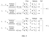
- the decoding coefficient matrix corresponding to the third antenna After the decoding coefficient matrix corresponding to the third antenna is obtained, serial-to-parallel conversion is performed on signals received by the first antenna and the second antenna, to be specific, the two signals are converted into four signals. Then the four signals obtained through serial-to-parallel conversion are respectively entered into respective multipliers, and a multiplication parameter in the multiplier is a corresponding decoding coefficient in the decoding coefficient vector A. Signals in a second timeslot of the first antenna and in the second timeslot of the second antenna need to be conjugated (Conj means performing conjugation) before being entered into a corresponding multiplier. Finally, signals obtained after multiplication are added to each other, to obtain a decoded signal ⁇ 1 corresponding to the third antenna. Likewise, the decoding coefficient vector B may be used to obtain a decoded signal ⁇ 2 corresponding to the fourth antenna.
- the decoded signal ⁇ 1 that is obtained after decoding and that corresponds to the first antenna is related only to a transmit signal s 1 , and the transmit signal s 1 may be obtained because the decoded signal ⁇ 1 and the decoding coefficient vector A are known.
- the decoded signal ⁇ 2 that is obtained after decoding and that corresponds to the second antenna is related only to a transmit signal s 2 , and the transmit signal s 2 may be obtained because the decoded signal ⁇ 2 and the decoding coefficient vector B are known.
- ⁇ rx 1 is a phase noise coefficient corresponding to the received signal y 1
- ⁇ rx 1 ′ is a phase noise coefficient corresponding to the received signal y 1 ′
- ⁇ rx 2 is a phase noise coefficient corresponding to the received signal y 2
- ⁇ rx 2 ′ is a phase noise coefficient corresponding to the received signal y 2 ′
- ⁇ tx 1 is a phase noise coefficient corresponding to the transmitted signal s 1
- ⁇ tx 1 ′ is a phase noise coefficient corresponding to a transmitted signal - s 2 *
- ⁇ tx 2 is a phase noise coefficient corresponding to the transmitted signal s 2
- ⁇ tx 2 ′ is a phase noise coefficient corresponding to a transmitted signal s 1 * .
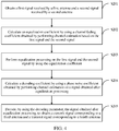
- FIG. 3 is a flowchart of a signal decoding method according to Embodiment 1 of the present invention.
- the signal decoding method provided in this embodiment is applied to a MIMO system, the MIMO system includes a signal transmit end and a signal receive end, the signal receive end includes a first antenna and a second antenna, and the signal transmit end includes a third antenna and a fourth antenna.
- the method includes the following steps.
- Step S101 Obtain a first signal received by the first antenna and a second signal received by the second antenna, where the first signal and the second signal are from the third antenna and the fourth antenna of the signal transmit end.
- the MIMO system in this embodiment is a 2 ⁇ 2 transceiver system, to be specific, the signal receive end has two antennas: the first antenna and the second antenna, and the signal transmit end has two antennas: the third antenna and the fourth antenna.
- two different signals are obtained after serial-to-parallel conversion is performed on a signal s , and are a transmit signal s 1 and a transmit signal s 2 .
- the third antenna transmits the signal s 1
- the fourth antenna transmits the signal s 2 ;
- the third antenna transmits a signal - s 2 *
- the fourth antenna transmits a signal s 1 * ("*" represents a conjugate complex number).
- the signal s 1 and the signal - s 2 * transmitted by the third antenna are referred to as a first transmitted signal, and a signal s 2 and a signal s 1 * transmitted by the fourth antenna are referred to as a second transmitted signal.
- the first antenna receives a signal y 1
- the second antenna receives a signal y 2
- the first antenna receives a signal y 1 ′
- the second antenna receives a signal y 2 ′
- the signal y 1 and the signal y 1 ′ are referred to as the first signal
- the signal y 2 and the signal y 2 ′ are referred to as the second signal.
- Step S102 Calculate a decoding coefficient by using a channel fading coefficient and a phase noise coefficient that are obtained by performing channel estimation based on the first signal and the second signal.
- a signal fading degree needs to be calculated, so as to compensate for the received first signal and second signal in a decoding process.
- the signal fading degree is usually indicated by the channel fading coefficient, and the channel fading coefficient is obtained through channel estimation.
- a decoding parameter is obtained by using the channel fading coefficient, so as to decode the first signal and the second signal to obtain the transmit signal s 1 and the transmit signal s 2 .
- a signal received by the signal receive end is affected by attenuation and also by phase noises of the signal transmit end and phase noises of the signal receive end.
- the signal transmit end includes two antennas
- the signal receive end includes two antennas
- the phase noises also have four values that respectively correspond to the four antennas.
- the phase noises of the signal transmit end and the phase noises of the signal receive end are mutually independent of each other.
- the decoding parameter in the prior art only the channel fading coefficient is considered, and no phase noise coefficient is considered. Consequently, the signal s 1 and the signal s 2 that are obtained through decoding interfere with each other, and decoding performance is relatively poor.
- the decoding parameter not only the channel fading coefficient is considered, but also a phase noise coefficient of the signal transmit end and a phase noise coefficient of the signal receive end are considered.
- the phase noise coefficient may also be obtained through channel estimation.
- the channel fading coefficient and the phase noise coefficient may be obtained by performing channel estimation once, to be specific, a phase noise is used as a part of a channel.
- the channel fading coefficient and the phase noise coefficient are calculated as a whole. If a channel whose phase noise is not considered is H , a channel whose phase noise is considered is He j ⁇ . Then the channel fading coefficient and the phase noise coefficient are used as a whole to obtain the decoding coefficient. It should be noted that, if the phase noise is considered in the channel, because the phase noise changes dynamically over time, the channel also dynamically changes, and the decoding coefficient obtained through calculation also dynamically changes.
- the signal transmit end needs to periodically send a training sequence to perform channel estimation, to obtain a decoding coefficient corresponding to the training sequence, and when the first signal and the second signal are not received signals corresponding to the training sequence, decoding coefficients respectively corresponding to the first signal and the second signal need to be estimated through an interpolation or in another manner.
- a start time point of a time period T is tl
- a corresponding decoding coefficient is m1
- an end time point is t2
- a corresponding decoding coefficient is m2.
- a receiving time of the first signal and the second signal is t3 and t2>t3>tl
- a corresponding decoding coefficient m3 may be equal to m1+(m2-m1)(t3-t1)/(t2-t1).
- the channel fading coefficient and the phase noise coefficient may be obtained by performing channel estimation twice, to be specific, the channel fading coefficient is obtained by performing channel estimation for a first time, and the phase noise coefficient is obtained by performing channel estimation for a second time.
- performing channel estimation twice can greatly reduce a workload of channel estimation performed for a single time, thereby improving decoding efficiency. For example, if the training-based channel estimation method is used, when channel estimation is performed once, a length of a training sequence for the channel estimation is L+1 (L is a channel impulse response length, and L is greater than 1 when channel equalization is not performed).
- L+1 is a channel impulse response length, and L is greater than 1 when channel equalization is not performed.
- channel estimation may be performed at a very long interval.
- the channel estimation performed twice is described in detail in the following embodiment, and details are not described herein.
- Step S103 Decode the first signal and the second signal by using the decoding coefficient, to respectively obtain a first decoded signal and a second decoded signal.
- the decoding parameter is obtained based on the channel fading coefficient and the phase noise coefficient, and the first signal and the second signal are decoded by using the decoding parameter to obtain the first decoded signal and the second decoded signal.
- the first decoded signal is related only to the transmit signal s 1 corresponding to the third antenna and is unrelated to the transmit signal s 2 corresponding to the fourth antenna
- the second decoded signal is related only to the transmit signal s 1 corresponding to the fourth antenna and is unrelated to the transmit signal s 2 corresponding to the third antenna. It may be learned from FIG.
- a signal transmitted by the third antenna is a first transmitted signal
- a signal transmitted by the fourth antenna is a second transmitted signal.
- the channel fading coefficient is obtained by considering channel fading
- the phase noise coefficient is obtained by considering the phase noises of the signal transmit end and the phase noises of the signal receive end
- the first signal and the second signal are decoded by using the decoding parameter obtained based on the channel fading coefficient and the phase noise coefficient.
- An obtained decoded signal is a signal not interfered with by another signal, thereby achieving a good decoding effect.
- FIG. 4 is a flowchart of a signal decoding method according to Embodiment 2 of the present invention.
- the signal decoding method provided in this embodiment includes the following steps.
- Step S201 Obtain a first signal received by a first antenna and a second signal received by a second antenna, where the first signal and the second signal are from a third antenna and a fourth antenna of a signal transmit end.
- step S201 is the same as step S101 in Embodiment 1, details are not described herein again.
- Step S202 Calculate an equalization coefficient by using a channel fading coefficient obtained by performing channel estimation based on the first signal and the second signal.
- channel estimation is performed twice in this embodiment, the channel fading coefficient is obtained by performing channel estimation for a first time, and a phase noise coefficient is obtained by performing channel estimation for a second time.
- channel fading coefficients obtained by performing channel estimation for a first time are h 11 , h 12 , h 21 , and h 22 .
- h 11 is a channel fading coefficient from the third antenna to the first antenna
- h 12 is a channel fading coefficient from the fourth antenna to the first antenna
- h 21 is a channel fading coefficient from the third antenna to the second antenna
- h 22 is a channel fading coefficient from the fourth antenna to the second antenna.
- Step S203 Perform equalization processing on the first signal and the second signal by using the equalization coefficient.
- the channel fading coefficient obtained through channel estimation is used to obtain the equalization coefficient, and equalization processing is performed on the first signal and the second signal by using the equalization coefficient, to cancel impact of channel fading on the transmit signal. In this way, only a phase noise needs to be considered when channel estimation is performed for a second time, so as to reduce a workload of channel estimation.
- a specific equalization processing process may include the following: The first signal and the second signal are first preprocessed to obtain a first group of four signals and a second group of four signals, where the first group of four signals and the second group of four signals each include a first timeslot of the first signal, a conjugate of a second timeslot of the first signal, the first timeslot of the second signal, and a conjugate of the second timeslot of the second signal.
- serial-to-parallel conversion may be performed twice on each of the first signal and the second signal, to obtain the first timeslot and the second timeslot of the first signal in the two groups of four signals, and the first timeslot and the second timeslot of the second signal, and then conjugation is performed on the second timeslot of the first signal and the second timeslot of the second signal in the two groups of four signals.
- the equalization processing is filtering the two groups of four signals by using the equalization coefficient.
- the equalization processing step may be performed in time domain, or may be performed in frequency domain. If equalization processing is performed in time domain, the equalization coefficient is a time-domain equalization coefficient, and if equalization processing is performed in frequency domain, the equalization coefficient is a frequency-domain equalization coefficient. Because the first signal and the second signal are time-domain signals, equalization processing only needs to be directly performed in time domain.
- the equalization processing is performing convolution on the two groups of four time-domain signals by using the equalization coefficient. However, if equalization processing is performed in frequency domain, the first signal and the second signal need to be converted from time-domain signals into frequency-domain signals, and then equalization processing is performed.
- the equalization processing means that the two groups of four signals are multiplied by using the equalization coefficient, and then signals obtained after equalization processing are converted into time-domain signals, so as to ensure that decoding in step S204 is performed in time domain.
- the following formula for equalization processing is performed in time domain. Equalization processing may be performed in frequency domain with reference to these formulas.
- An equalization coefficient corresponding to the first group of four signals is a first group of equalization coefficients, and the first group of equalization coefficients include a first equalization coefficient W 11 , a second equalization coefficient W 12 , a third equalization coefficient W 13 , and a fourth equalization coefficient W 14 .
- the first timeslot of the first signal is filtered by using the first equalization coefficient W 11
- the second timeslot of the first signal is filtered by using the second equalization coefficient W 12
- the first timeslot of the second signal is filtered by using the third equalization coefficient W 13
- the second timeslot of the second signal is filtered by using the fourth equalization coefficient W 14 .
- An equalization coefficient corresponding to the second group of four signals is a second group of equalization coefficients, and the second group of equalization coefficients include a fifth equalization coefficient W 21 , a sixth equalization coefficient W 22 , a seventh equalization coefficient W 23 , and an eighth equalization coefficient W 24 .
- the first timeslot of the first signal is filtered by using the fifth equalization coefficient W 21
- the second timeslot of the first signal is filtered by using the sixth equalization coefficient W 22
- the first timeslot of the second signal is filtered by using the seventh equalization coefficient W 23
- the second timeslot of the second signal is filtered by using the eighth equalization coefficient W 24 .
- the equalization coefficient needs to meet the condition.
- the first equalization coefficient W 11 1 h 11
- the second equalization coefficient W 12 1 h 12 ⁇
- the third equalization coefficient W 13 1 h 21
- the fourth equalization coefficient W 14 1 h 22 ⁇ .
- the fifth equalization coefficient W 21 1 h 12
- the sixth equalization coefficient W 22 ⁇ 1 h 11 ⁇
- the seventh equalization coefficient W 23 1 h 22
- the eighth equalization coefficient W 24 ⁇ 1 h 21 ⁇ .
- h 11 is a channel fading coefficient from the third antenna to the first antenna
- h 12 is a channel fading coefficient from the fourth antenna to the first antenna
- h 21 is a channel fading coefficient from the third antenna to the second antenna
- h 22 is a channel fading coefficient from the fourth antenna to the second antenna.
- h 12 ⁇ is a conjugate of h 12
- h 22 ⁇ is a conjugate of h 22
- h 11 ⁇ is a conjugate of h 11
- h 21 ⁇ is a conjugate of h 21 .
- a MIMO system with dual-antenna transmission and dual-antenna receiving in this embodiment has the following features:
- h 21 and h 12 ⁇ h 22 .
- a third signal and a fourth signal that correspond to the first group of four signals, and a fifth signal and a sixth signal that correspond to the second group of four signals are obtained.
- the third signal includes the first timeslot ⁇ 1 and the second timeslot y ⁇ 1 ′
- the fourth signal includes the first timeslot ⁇ 2 and the second timeslot y ⁇ 2 ′
- the fifth signal includes the first timeslot ⁇ 1 and the second timeslot y ⁇ 1 ′
- the sixth signal includes the first timeslot ⁇ 2 and the second timeslot y ⁇ 2 ′
- ⁇ 11 ⁇ tx 1 + ⁇ rx 1
- ⁇ 12 ⁇ tx 2 + ⁇ rx 1
- ⁇ 11 ′ ⁇ t ⁇ 1 ′ + ⁇ r ⁇ 1 ′
- ⁇ 12 ′ ⁇ t ⁇ 2 ′ + ⁇ r ⁇ 1 ′
- ⁇ 21 ⁇ tx1 + ⁇ rx2
- ⁇ 22 ⁇ tx 2 + ⁇ rx 2
- ⁇ ' 21 ⁇ ' tx1 + ⁇ ' rx2
- ⁇ 22 ′ ⁇ t ⁇ 2 ′ + ⁇ r ⁇ 2 ′
- ⁇ rx 1 is a phase noise coefficient corresponding to the first timeslot of the first signal
- ⁇ ' rx1 is a phase noise coefficient corresponding to the second timeslot of the first signal
- ⁇ rx 2 is a phase noise coefficient corresponding to the first timeslot of the second signal
- ⁇ ' rx 2
- Step S204 Calculate a decoding coefficient by using a phase noise coefficient obtained by performing channel estimation on a signal obtained after equalization processing.
- Equalization processing is performed on the first signal and the second signal in this embodiment to cancel interference caused to a transmitted signal of the signal transmit end by the four channels between the first antenna and the fourth antenna.
- the third signal is considered as a signal received by the first antenna of the signal receive end
- the fourth signal is considered as a signal received by the second antenna
- the four channels between the first antenna and the fourth antenna can be considered as flat channels, in other words, channels without fading.
- the fifth signal is considered as a signal received by the first antenna
- the sixth signal is considered as a signal received by the second antenna
- the four channels between the first antenna and the fourth antenna may also be considered as channels without intercode interference.
- channel estimation is performed on a signal obtained after equalization processing, so as to obtain a phase noise coefficient. Specifically, channel estimation is performed based on the third signal and the fourth signal to obtain a first group of phase noise coefficients, to be specific, phase noise coefficients in phase noise matrices H 1 and H 2 . Channel estimation is performed based on the fifth signal and the sixth signal to obtain a second group of phase noise coefficients, to be specific, phase noise coefficients in phase noise matrices H 3 and H 4 .
- a decoding coefficient is obtained based on the phase noise coefficient.
- the decoding coefficient is used for decoding, so that a signal obtained through decoding is related only to the transmit signal s 1 or the transmit signal s 2 .
- a first group of decoding coefficients are calculated based on the first group of phase noise coefficients, and the first group of decoding coefficients include a first decoding coefficient W 11 , a second decoding coefficient W 12 , a third decoding coefficient W 13 , and a fourth decoding coefficient W 14 .
- the first decoding coefficient needs to meet a condition that a first decoded signal obtained through decoding is related only to the transmit signal s 1 corresponding to the third antenna.
- w 11 e ⁇ j ⁇ 11 ′
- w 12 ⁇ 2 e j ⁇ 12
- w 13 ⁇ 2 e ⁇ j ⁇ 21 ′
- w 14 e j ⁇ 22 .
- w 11 ⁇ 1 ⁇ e ⁇ j ⁇ 11 ′
- w 12 - ⁇ e j ⁇ 12
- w 13 ⁇ ⁇ e ⁇ j ⁇ 21 ′
- w 14 ⁇ 1 ⁇ e j ⁇ 22 .
- a second group of decoding coefficients are calculated based on the second group of phase noise coefficients, and the second group of decoding coefficients include a fifth decoding coefficient W 21 , a sixth decoding coefficient W 22 , a seventh decoding coefficient W 23 , and an eighth decoding coefficient W 24 .
- the second decoding coefficient needs to meet a condition that a second decoded signal obtained through decoding is related only to the transmit signal s 2 corresponding to the fourth antenna.
- w 21 ⁇ 2 e ⁇ j ⁇ 12 ′
- w 22 e j ⁇ 12
- w 23 e ⁇ j ⁇ 22 ′
- w 24 ⁇ 2 e j ⁇ 21 .
- w 21 ⁇ e ⁇ j ⁇ 12 ′
- w 22 1 ⁇ e j ⁇ 11
- w 23 1 ⁇ e ⁇ j ⁇ 22 ′
- w 24 ⁇ e j ⁇ 21 .
- Step S205 Decode, by using the decoding parameter, the signal obtained after equalization processing, to obtain a transmit signal corresponding to the third antenna and a transmit signal corresponding to the fourth antenna.
- the third signal is decoded by using the first group of decoding coefficients.
- a specific decoding process may be: multiplying the first timeslot of the third signal and the first decoding coefficient, multiplying the second timeslot of the third signal and the second decoding coefficient, multiplying the first timeslot of the fourth signal and the third decoding coefficient, multiplying the second timeslot of the fourth signal and the fourth decoding coefficient, and adding multiplying results to each other to obtain the first decoded signal ⁇ 1 .
- the fourth signal is decoded by using the second group of decoding coefficients.
- a specific decoding process may be: multiplying the first timeslot of the fifth signal and the fifth decoding coefficient, multiplying the second timeslot of the fifth signal and the sixth decoding coefficient, multiplying the first timeslot of the sixth signal and the seventh decoding coefficient, multiplying the second timeslot of the sixth signal and the eighth decoding coefficient, and adding multiplying results to each other to obtain the second decoded signal ⁇ 2 .
- the first decoded signal ⁇ 1 is related only to the transmit signal s 1 corresponding to the third antenna, and is not interfered with by the transmit signal s 2 , and a good decoding result is obtained.
- the second decoded signal ⁇ 2 is related only to the transmit signal ⁇ 2 corresponding to the fourth antenna, and is not interfered with by the transmit signal ⁇ 1 , and a good decoding result is obtained.
- the channel fading coefficient is obtained by performing channel estimation for a first time, and the equalization coefficient is obtained based on the channel fading coefficient, so as to perform equalization processing on the first signal and the second signal to obtain the third signal and the fourth signal.
- channel estimation is performed for a second time based on the third signal and the fourth signal to obtain the decoding coefficient, and the first signal and the second signal are decoded by using the decoding coefficient, to respectively obtain the first decoded signal and the second decoded signal.
- a channel corresponding to the third signal and a channel corresponding to the fourth signal may be considered as channels without intercode interference, thereby improving decoding efficiency.
- channel estimation performed for a second time is to obtain a phase noise coefficient. Because a phase noise coefficient dynamically changes, if a training-based channel estimation method is used, after a phase noise coefficient corresponding to a training sequence is obtained, an actual phase noise coefficient corresponding to the signal (the third signal and the fourth signal) may be obtained through an interpolation.
- FIG. 6 is a structural block diagram of a signal decoding apparatus according to Embodiment 3 of the present invention.
- the signal decoding apparatus provided in this embodiment is applied to a MIMO system, the MIMO system includes a signal transmit end and a signal receive end, the signal receive end includes a first antenna and a second antenna, and the signal transmit end includes a third antenna and a fourth antenna.
- the apparatus includes: a signal obtaining unit 11, a decoding coefficient calculation unit 21, and a decoding unit 31.
- the signal obtaining unit 11 is configured to obtain a first signal received by the first antenna and a second signal received by the second antenna, where the first signal and the second signal are from the third antenna and the fourth antenna of the signal transmit end.
- the decoding coefficient calculation unit 21 is configured to calculate a decoding coefficient by using a channel fading coefficient and a phase noise coefficient that are obtained by performing channel estimation based on the first signal and the second signal, where the channel fading coefficient includes channel fading coefficients respectively corresponding to four channels formed between the first antenna, the second antenna, the third antenna, and the fourth antenna, the phase noise coefficient includes a phase noise coefficient of the signal transmit end and a phase noise coefficient of the signal receive end, and a phase noise corresponding to the phase noise coefficient of the signal transmit end and a phase noise corresponding to the phase noise coefficient of the signal receive end are independent of each other.
- the decoding unit 31 is configured to decode the first signal and the second signal by using the decoding coefficient, to respectively obtain a first decoded signal and a second decoded signal, where the first decoded signal is related only to a transmit signal corresponding to the third antenna and is unrelated to a transmit signal corresponding to the fourth antenna, and the second decoded signal is related only to the transmit signal corresponding to the fourth antenna and is unrelated to the transmit signal corresponding to the third antenna.
- the channel fading coefficient is obtained by considering channel fading
- the phase noise coefficient is obtained by considering the phase noises of the signal transmit end and the phase noises of the signal receive end
- the first signal and the second signal are decoded by using the decoding parameter obtained based on the channel fading coefficient and the phase noise coefficient.
- An obtained decoded signal is a signal not interfered with by another signal, thereby achieving a good decoding effect.
- the channel fading coefficient and the phase noise coefficient may be obtained by performing channel estimation once, to be specific, during channel estimation, the channel fading coefficient and the phase noise coefficient are calculated as a whole. Then the channel fading coefficient and the phase noise coefficient are used as a whole to obtain the decoding coefficient.
- the channel fading coefficient and the phase noise coefficient may be obtained by performing channel estimation twice, to be specific, the channel fading coefficient is obtained by performing channel estimation for a first time, and the phase noise coefficient is obtained by performing channel estimation for a second time.
- the decoding coefficient calculation unit 21 specifically includes: an equalization coefficient calculation unit 211, an equalization unit 212, and a decoding coefficient calculation subunit 213.
- the equalization coefficient calculation unit 211 is configured to calculate an equalization coefficient by using the channel fading coefficient obtained by performing channel estimation based on the first signal and the second signal.
- the equalization unit 212 is configured to perform equalization processing on the first signal and the second signal by using the equalization coefficient.
- the decoding coefficient calculation subunit 213 is configured to calculate the decoding coefficient by using the phase noise coefficient obtained by performing channel estimation on a signal obtained after equalization processing.
- the equalization coefficient calculation unit 211 is specifically configured to calculate a first group of equalization coefficients and a second group of equalization coefficients by using the channel fading coefficient obtained by performing channel estimation based on the first signal and the second signal.
- the equalization unit 212 specifically includes a preprocessing unit and a filter unit, and the filter unit includes a first filter unit and a second filter unit.
- the preprocessing unit is configured to preprocess the first signal and the second signal to obtain a first group of four signals and a second group of four signals, where the first group of four signals and the second group of four signals each include the first timeslot of the first signal, a conjugate of the second timeslot of the first signal, the first timeslot of the second signal, and a conjugate of the second timeslot of the second signal.
- the first filter unit is configured to filter the first group of four signals by using the first group of equalization coefficients to obtain a third signal and a fourth signal, where the third signal and the fourth signal each correspond to the timeslot.
- the second filter unit is configured to filter the second group of four signals by using the second group of equalization coefficients to obtain a fifth signal and a sixth signal, where the fifth signal and the sixth signal each correspond to the timeslot.
- the first filter unit is specifically configured to:
- the second filter unit is specifically configured to:
- the decoding coefficient calculation subunit 213 may be specifically configured to:
- the decoding unit 31 includes a first decoding unit 311 and a second decoding unit 312.
- the first decoding unit 311 is configured to: decode the third signal and the fourth signal by using the first group of decoding coefficients, to obtain the first decoded signal.
- the second decoding unit 312 is configured to: decode the fifth signal and the sixth signal by using the second group of decoding coefficients, to obtain the second decoded signal.
- the first decoding unit 311 is specifically configured to: multiply the first timeslot of the third signal and the first decoding coefficient, multiply the second timeslot of the third signal and the second decoding coefficient, multiply the first timeslot of the fourth signal and the third decoding coefficient, multiply the second timeslot of the fourth signal and the fourth decoding coefficient, and add multiplying results to each other to obtain the first decoded signal.
- the second decoding unit 312 is specifically configured to: multiply the first timeslot of the fifth signal and the fifth decoding coefficient, multiply the second timeslot of the fifth signal and the sixth decoding coefficient, multiply the first timeslot of the sixth signal and the seventh decoding coefficient, multiply the second timeslot of the sixth signal and the eighth decoding coefficient, and add multiplying results to each other to obtain the second decoded signal.
- the equalization unit 212 is specifically configured to: in time domain, perform equalization processing on the first signal and the second signal by using the equalization coefficient.
- the equalization unit 212 is specifically configured to: in frequency domain, perform equalization processing on the first signal and the second signal by using the equalization coefficient.
- the equalization unit 212 may be implemented by using a filter, and may be specifically implemented by using a transverse filter.
- Embodiment 4 of the present invention provides a signal decoding device, the device is applied to a MIMO system, the MIMO system includes a signal transmit end and a signal receive end, the signal receive end includes a first antenna and a second antenna, and the signal transmit end includes a third antenna and a fourth antenna.
- the device includes a memory and a processor, the memory is configured to store a group of program instructions, and the processor is configured to invoke the program instructions stored in the memory, to perform the following operations:
- the processor may be a central processing unit (Central Processing Unit, CPU), and the memory may be an internal memory of a random access memory (Random Access Memory, RAM) type.
- the processor and the memory may be integrated into one or more independent circuits or hardware, for example, an application-specific integrated circuit (Application-Specific Integrated Circuit, ASIC).
- ASIC Application-Specific Integrated Circuit
- the program may be stored in a computer readable storage medium. When the program runs, the steps of the method embodiments are performed.
- the storage medium may be at least one of the following media: media that are capable of storing program code, such as a read-only memory (English: read-only memory, ROM for short), a RAM, a magnetic disk, or an optical disc.
Landscapes
- Engineering & Computer Science (AREA)
- Computer Networks & Wireless Communication (AREA)
- Signal Processing (AREA)
- Radio Transmission System (AREA)
- Noise Elimination (AREA)
Description
- The present invention relates to the communications field, and in particular, to a signal decoding method, apparatus, and device.
- In the field of wireless communications, a multiple-input multiple-output (Multiple-Input Multiple-Output, MIMO) technology is widely applied at present. The MIMO technology means that a plurality of antennas are used at both a transmit end and a receive end of signals, and signals are transmitted and received by using the plurality of antennas at the transmit end and the receive end, so as to improve communication quality.
- To further increase a gain of a MIMO system, a space-time coding technology emerges, to be specific, signal coding is performed in two dimensions: spatial domain and time domain, so that spatial diversity of a plurality of antennas is used in space to increase a system gain.
- Currently, a relatively mature space-time coding technology includes an Alamouti coding scheme.
FIG. 1 is an architectural diagram of an Alamouti space-time coding scheme. In this scheme, a signal transmit end has two antennas: a first antenna and a second antenna, and a signal receive end also has two antennas: a third antenna and a fourth antenna. Two different signals are obtained after serial-to-parallel conversion is performed on a signal s, and are a transmit signal s 1 and a transmit signal s 2. After orthogonal space-time coding, in a first timeslot, the third antenna transmits the signal s 1, and the fourth antenna transmits the signal s 2; in a second timeslot, the third antenna transmits a signal -s 2 *, and the fourth antenna transmits a signal s 1 * ("*" represents a conjugate complex number). At the signal receive end, in the first timeslot, the first antenna receives a signal y 1, and the second antenna receives a signal y 2; in the second timeslot, the first antenna receives asignal 
signal 
- A phase noise (Phase Noise) means that a phase of an output signal randomly changes due to various noises at the transmit end of a signal. A longer wavelength and a lower frequency of a radio wave lead to a lower phase noise; otherwise, a shorter wavelength and a higher frequency of a radio wave lead to a higher phase noise. The Alamouti coding scheme is mainly pertinent to a radio wave with a relatively long wavelength and a relatively low frequency, for example, a long wave (with a wavelength of 1 km to 10 km and a frequency range of 30 KHz to 300 KHz) and a medium wave (with a wavelength range of 100 m to 1000 m and a frequency range of 300 KHz to 3000 KHz). Because a phase noise is very low and therefore can be ignored, the decoded signal ŝ 1 obtained by the signal receive end through decoding is related only to the transmit signal s 1 and is unrelated to the transmit signal s 2 . The decoded signal ŝ 2 obtained through decoding is related only to the transmit signal s 2 and is unrelated to the transmit signal s 2. A decoding result is good. However, for a radio wave with a relatively short wavelength and a relatively high frequency, for example, a microwave (with a wavelength range of 0.1 mm to 10 dm and a frequency range of 3000 MHz to 3000 GHz), a phase noise is usually high. Consequently, the decoded signal ŝ 1 obtained by the signal receive end through decoding is related to both the transmit signal s 1 and the transmit signal s 2, to be specific, the transmit signal s 2 causes interference to the transmit signal s 1. The decoded signal ŝ 2 is related to both the transmit signal s 2 and the transmit signal s 1, to be specific, the transmit signal s 1 causes interference to the transmit signal s 2. A decoding result is relatively poor. Therefore, there is an urgent need for a method that can be applied to decode a radio wave with a relatively short wavelength and a relatively high frequency, to improve decoding performance.
- S. M. Alamouti, "A Simple Transmit Diversity Technique for Wireless Communications", IEEE Journal on selected areas in communications, vol. 16, no. 8, 01-Oct-1998, p. 1454-1455 describes a two-branch transmit diversity scheme. Using two transmit antennas and one receive antenna the scheme provides the same diversity order as maximal-ratio receiver combining (MRRC) with one transmit antenna, and two receive antennas. The scheme can be generalized to two transmit antennas and M receive antennas to provide a diversity order of 2M.
-
US 2007/0098092 A1 describes a technique for generating common phase error (CPE) estimates in a multicarrier receiver. The CPE estimates are generated for each channel between two or more transmit antennas and the multicarrier receiver. - To resolve the foregoing technical problem, embodiments of the present invention provide a signal decoding method, apparatus, and device, so that a good decoding result can be obtained even if phase noises exist at a signal transmit end and a signal receive end in a 2×2 MIMO system.
- An embodiment of the present invention provides a signal decoding method, where the method is applied to a MIMO system, the MIMO system includes a signal transmit end and a signal receive end, the signal receive end includes a first antenna and a second antenna, and the signal transmit end includes a third antenna and a fourth antenna; and
the method includes: - obtaining a first signal received by the first antenna and a second signal received by the second antenna, where the first signal and the second signal are from the third antenna and the fourth antenna of the signal transmit end;
- calculating a decoding coefficient by using a channel fading coefficient and a phase noise coefficient that are obtained by performing channel estimation based on the first signal and the second signal, where the channel fading coefficient includes channel fading coefficients respectively corresponding to four channels formed between the first antenna, the second antenna, the third antenna, and the fourth antenna, and the phase noise coefficient includes a phase noise coefficient of the signal transmit end and a phase noise coefficient of the signal receive end; and
- decoding the first signal and the second signal by using the decoding coefficient, to respectively obtain a first decoded signal and a second decoded signal, where the first decoded signal is related only to a transmit signal corresponding to the third antenna and is unrelated to a transmit signal corresponding to the fourth antenna, the second decoded signal is related only to the transmit signal corresponding to the fourth antenna and is unrelated to the transmit signal corresponding to the third antenna, and the transmit signal is a signal before encoding;
wherein the calculating a decoding coefficient by using a channel fading coefficient and a phase noise coefficient that are obtained by performing channel estimation based on the first signal and the second signal includes:- calculating an equalization coefficient by using the channel fading coefficient obtained by performing channel estimation for a first time based on the first signal and the second signal;
- performing equalization processing on the first signal and the second signal by using the equalization coefficient; and
- Preferably, the first signal and the second signal correspond to a same timeslot, and the timeslot includes a first timeslot and a second timeslot;
the calculating an equalization coefficient by using the channel fading coefficient obtained by performing channel estimation based on the first signal and the second signal includes: - calculating a first group of equalization coefficients and a second group of equalization coefficients by using the channel fading coefficient obtained by performing channel estimation based on the first signal and the second signal; and
- the performing equalization processing on the first signal and the second signal by using the equalization coefficient includes:
- preprocessing the first signal and the second signal to obtain a first group of four signals and a second group of four signals, where the first group of four signals and the second group of four signals each include the first timeslot of the first signal, a conjugate of the second timeslot of the first signal, the first timeslot of the second signal, and a conjugate of the second timeslot of the second signal;
- filtering the first group of four signals by using the first group of equalization coefficients to obtain a third signal and a fourth signal, where the third signal and the fourth signal each correspond to the timeslot; and
- filtering the second group of four signals by using the second group of equalization coefficients to obtain a fifth signal and a sixth signal, where the fifth signal and the sixth signal each correspond to the timeslot.
- Preferably, the first group of equalization coefficients include a first equalization coefficient, a second equalization coefficient, a third equalization coefficient, and a fourth equalization coefficient; and
the filtering the first group of four signals by using the first group of equalization coefficients to obtain a third signal and a fourth signal includes: - filtering the first timeslot of the first signal by using the first equalization coefficient, to obtain the first timeslot of the third signal;
- filtering the conjugate of the second timeslot of the first signal by using the second equalization coefficient, to obtain the second timeslot of the third signal;
- filtering the first timeslot of the second signal by using the third equalization coefficient, to obtain the first timeslot of the fourth signal; and
- filtering the conjugate of the second timeslot of the second signal by using the fourth equalization coefficient, to obtain the second timeslot of the fourth signal.
- Preferably, the first
equalization coefficient 
equalization coefficient 
equalization coefficient 
equalization coefficient 
h 11 is a channel fading coefficient from the third antenna to the first antenna,

- Preferably, the second group of equalization coefficients include a fifth equalization coefficient, a sixth equalization coefficient, a seventh equalization coefficient, and an eighth equalization coefficient; and
the filtering the second group of four signals by using the second group of equalization coefficients to obtain a fifth signal and a sixth signal includes: - filtering the first timeslot of the first signal by using the fifth equalization coefficient, to obtain the first timeslot of the fifth signal;
- filtering the conjugate of the second timeslot of the first signal by using the sixth equalization coefficient, to obtain the second timeslot of the fifth signal;
- filtering the first timeslot of the second signal by using the seventh equalization coefficient, to obtain the first timeslot of the sixth signal; and
- filtering the conjugate of the second timeslot of the second signal by using the eighth equalization coefficient, to obtain the second timeslot of the sixth signal.
- Preferably, the fifth
equalization coefficient 
equalization coefficient 
equalization coefficient 
equalization coefficient 
h 12 is a channel fading coefficient from the fourth antenna to the first antenna,

- Preferably, the calculating the decoding coefficient by using the phase noise coefficient obtained by performing channel estimation on a signal obtained after equalization processing includes:
- calculating a first group of decoding coefficients by using a first group of phase noise coefficients obtained by performing channel estimation based on the third signal and the fourth signal; and
- calculating a second group of decoding coefficients by using a second group of phase noise coefficients obtained by performing channel estimation based on the fifth signal and the sixth signal; and
- the decoding the first signal and the second signal by using the decoding coefficient, to respectively obtain a first decoded signal and a second decoded signal includes:
- decoding the third signal and the fourth signal by using the first group of decoding coefficients, to obtain the first decoded signal; and
- decoding the fifth signal and the sixth signal by using the second group of decoding coefficients, to obtain the second decoded signal.
- Preferably, the first group of decoding coefficients include a first decoding coefficient, a second decoding coefficient, a third decoding coefficient, and a fourth decoding coefficient; and
the decoding the third signal and the fourth signal by using the first group of decoding coefficients, to obtain the first decoded signal includes:
multiplying the first timeslot of the third signal and the first decoding coefficient, multiplying the second timeslot of the third signal and the second decoding coefficient, multiplying the first timeslot of the fourth signal and the third decoding coefficient, multiplying the second timeslot of the fourth signal and the fourth decoding coefficient, and adding multiplying results to each other to obtain the first decoded signal. - Preferably, the first
decoding coefficient 
12 , the thirddecoding coefficient 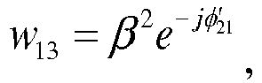
22 ; or - the first
decoding coefficient 
12 , the thirddecoding coefficient 
decoding coefficient 
- the first
decoding coefficient 
decoding coefficient 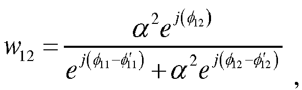
decoding coefficient 
decoding coefficient 
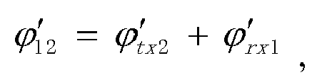
- ϕ 11 = ϕ tx1 + ϕ rx1 , ϕ 12 = ϕ tx2 + ϕ rx1,


- Preferably, the second group of decoding coefficients include a fifth decoding coefficient, a sixth decoding coefficient, a seventh decoding coefficient, and an eighth decoding coefficient; and
the decoding the fifth signal and the sixth signal by using the second group of decoding coefficients, to obtain the second decoded signal includes:
multiplying the first timeslot of the fifth signal and the fifth decoding coefficient, multiplying the second timeslot of the fifth signal and the sixth decoding coefficient, multiplying the first timeslot of the sixth signal and the seventh decoding coefficient, multiplying the second timeslot of the sixth signal and the eighth decoding coefficient, and adding multiplying results to each other to obtain the second decoded signal. - Preferably, the fifth decoding coefficient w 21= α 2 e -jφ'
12 , the sixth decoding coefficient w 22= e jφ12 , the seventh decoding coefficient w 23= e -jφ'12 , and the eighth decoding coefficient w 24= β 2 e jφ12 ; or
the fifth decoding coefficient w 21=αe -jφ'12 , the sixthdecoding coefficient 
decoding coefficient 
12 ; or
the fifthdecoding coefficient 
decoding coefficient 
decoding coefficient 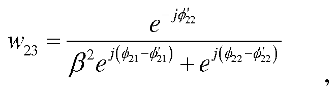
decoding coefficient 
ϕ 11 = ϕ tx1 + ϕ rx1, ϕ 12 = ϕ tx2 + ϕ rx1,


- Preferably, the performing equalization processing on the first signal and the second signal by using the equalization coefficient includes:
in time domain, performing equalization processing on the first signal and the second signal by using the equalization coefficient. - Preferably, the performing equalization processing on the first signal and the second signal by using the equalization coefficient includes:
in frequency domain, performing equalization processing on the first signal and the second signal by using the equalization coefficient. - An embodiment of the present invention provides a signal decoding apparatus, where the apparatus is applied to a MIMO system, the MIMO system includes a signal transmit end and a signal receive end, the signal receive end includes a first antenna and a second antenna, and the signal transmit end includes a third antenna and a fourth antenna; and
the apparatus includes: - a signal obtaining unit, a decoding coefficient calculation unit, and a decoding unit, where
- the signal obtaining unit is configured to obtain a first signal received by the first antenna and a second signal received by the second antenna, where the first signal and the second signal are from the third antenna and the fourth antenna of the signal transmit end;
- the decoding coefficient calculation unit is configured to calculate a decoding coefficient by using a channel fading coefficient and a phase noise coefficient that are obtained by performing channel estimation based on the first signal and the second signal, where the channel fading coefficient includes channel fading coefficients respectively corresponding to four channels formed between the first antenna, the second antenna, the third antenna, and the fourth antenna, and the phase noise coefficient includes a phase noise coefficient of the signal transmit end and a phase noise coefficient of the signal receive end; and
- the decoding unit is configured to decode the first signal and the second signal by using the decoding coefficient, to respectively obtain a first decoded signal and a second decoded signal, where the first decoded signal is related only to a transmit signal corresponding to the third antenna and is unrelated to a transmit signal corresponding to the fourth antenna, the second decoded signal is related only to the transmit signal corresponding to the fourth antenna and is unrelated to the transmit signal corresponding to the third antenna, and the transmit signal is a signal before encoding;
- an equalization coefficient calculation unit, an equalization unit, and a decoding coefficient calculation subunit, where
- the equalization coefficient calculation unit is configured to calculate an equalization coefficient by using the channel fading coefficient obtained by performing channel estimation for a first time based on the first signal and the second signal;
- the equalization unit is configured to perform equalization processing on the first signal and the second signal by using the equalization coefficient; and
- the decoding coefficient calculation subunit is configured to calculate the decoding coefficient by using the phase noise coefficient obtained by performing channel estimation for a second time on a signal obtained after equalization processing, wherein the performing channel estimation for a first time for obtaining the channel fading coefficient is performed at a longer interval than the performing channel estimation for a second time for obtaining the phase noise coefficient.
- Preferably, the first signal and the second signal correspond to a same timeslot, and the timeslot includes a first timeslot and a second timeslot;
the equalization coefficient calculation unit is specifically configured to calculate a first group of equalization coefficients and a second group of equalization coefficients by using the channel fading coefficient obtained by performing channel estimation based on the first signal and the second signal; and
the equalization unit specifically includes a preprocessing unit and a filter unit, and the filter unit includes a first filter unit and a second filter unit, where
the preprocessing unit is configured to preprocess the first signal and the second signal to obtain a first group of four signals and a second group of four signals, where the first group of four signals and the second group of four signals each include the first timeslot of the first signal, a conjugate of the second timeslot of the first signal, the first timeslot of the second signal, and a conjugate of the second timeslot of the second signal;
the first filter unit is configured to filter the first group of four signals by using the first group of equalization coefficients to obtain a third signal and a fourth signal, where the third signal and the fourth signal each correspond to the timeslot; and
the second filter unit is configured to filter the second group of four signals by using the second group of equalization coefficients to obtain a fifth signal and a sixth signal, where the fifth signal and the sixth signal each correspond to the timeslot. - Preferably, the first group of equalization coefficients include a first equalization coefficient, a second equalization coefficient, a third equalization coefficient, and a fourth equalization coefficient; and
the first filter unit is specifically configured to: - filter the first timeslot of the first signal by using the first equalization coefficient, to obtain the first timeslot of the third signal;
- filter the conjugate of the second timeslot of the first signal by using the second equalization coefficient, to obtain the second timeslot of the third signal;
- filter the first timeslot of the second signal by using the third equalization coefficient, to obtain the first timeslot of the fourth signal; and
- filter the conjugate of the second timeslot of the second signal by using the fourth equalization coefficient, to obtain the second timeslot of the fourth signal.
- Preferably, the first
equalization coefficient 
equalization coefficient 
equalization coefficient 
equalization coefficient 
h 11 is a channel fading coefficient from the third antenna to the first antenna,

- Preferably, the second group of equalization coefficients include a fifth equalization coefficient, a sixth equalization coefficient, a seventh equalization coefficient, and an eighth equalization coefficient; and
the second filter unit is specifically configured to: - filter the first timeslot of the first signal by using the fifth equalization coefficient, to obtain the first timeslot of the fifth signal;
- filter the conjugate of the second timeslot of the first signal by using the sixth equalization coefficient, to obtain the second timeslot of the fifth signal;
- filter the first timeslot of the second signal by using the seventh equalization coefficient, to obtain the first timeslot of the sixth signal; and
- filter the conjugate of the second timeslot of the second signal by using the eighth equalization coefficient, to obtain the second timeslot of the sixth signal.
- Preferably, the fifth
equalization coefficient 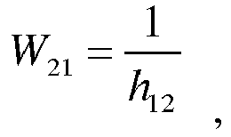
equalization coefficient 
equalization coefficient 
equalization coefficient 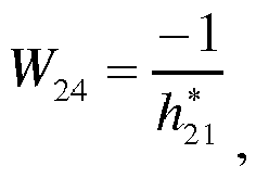
h 12 is a channel fading coefficient from the fourth antenna to the first antenna,

- Preferably, the decoding coefficient calculation subunit is specifically configured to:
- calculate a first group of decoding coefficients by using a first group of phase noise coefficients obtained by performing channel estimation based on the third signal and the fourth signal; and
- calculate a second group of decoding coefficients by using a second group of phase noise coefficients obtained by performing channel estimation based on the fifth signal and the sixth signal; and
- the decoding unit includes a first decoding unit and a second decoding unit, where
- the first decoding unit is configured to:
- decode the third signal and the fourth signal by using the first group of decoding coefficients, to obtain the first decoded signal; and
- the second decoding unit is configured to:
decode the fifth signal and the sixth signal by using the second group of decoding coefficients, to obtain the second decoded signal.
- Preferably, the first group of decoding coefficients include a first decoding coefficient, a second decoding coefficient, a third decoding coefficient, and a fourth decoding coefficient; and
the first decoding unit is specifically configured to:
multiply the first timeslot of the third signal and the first decoding coefficient, multiply the second timeslot of the third signal and the second decoding coefficient, multiply the first timeslot of the fourth signal and the third decoding coefficient, multiply the second timeslot of the fourth signal and the fourth decoding coefficient, and add multiplying results to each other to obtain the first decoded signal. - Preferably, the first
decoding coefficient 
12 , the thirddecoding coefficient 
22 ; or
the firstdecoding coefficient 
12 , the thirddecoding coefficient 
decoding coefficient 
the firstdecoding coefficient 
decoding coefficient 
decoding coefficient 
decoding coefficient 
ϕ 11 = ϕ tx1 + ϕ rx1, ϕ 12 = ϕ tx2 + ϕ rx1,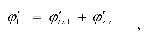


- Preferably, the second group of decoding coefficients include a fifth decoding coefficient, a sixth decoding coefficient, a seventh decoding coefficient, and an eighth decoding coefficient; and
the second decoding unit is specifically configured to:
multiply the first timeslot of the fifth signal and the fifth decoding coefficient, multiply the second timeslot of the fifth signal and the sixth decoding coefficient, multiply the first timeslot of the sixth signal and the seventh decoding coefficient, multiply the second timeslot of the sixth signal and the eighth decoding coefficient, and add multiplying results to each other to obtain the second decoded signal. - Preferably, the fifth decoding coefficient w 21=α 2 e -jφ'
12 , the sixth decoding coefficient w 22=e jφ11 , the seventh decoding coefficient w 23=e -jφ'22 , and the eighth decoding coefficient w 24=β 2 e jφ21 ; or
the fifth decoding coefficient w 21=αe -jφ'12 , the sixthdecoding coefficient 
decoding coefficient 
21 ; or
the fifthdecoding coefficient 
decoding coefficient 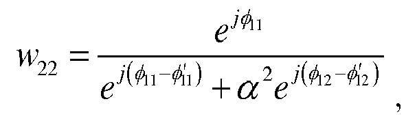
decoding coefficient 
decoding coefficient 
ϕ 11 = ϕ tx1 + ϕ rx1, ϕ 12 = ϕ tx2 + ϕ rx1,


- Preferably, the equalization unit is specifically configured to:
in time domain, perform equalization processing on the first signal and the second signal by using the equalization coefficient. - Preferably, the equalization unit is specifically configured to:
in frequency domain, perform equalization processing on the first signal and the second signal by using the equalization coefficient. - An embodiment of the present invention provides a signal decoding device, configured to perform any of the methods described herein.
- It may be learned from the foregoing technical solutions that, in the present invention, in a process of solving the decoding coefficient, the channel fading coefficient is obtained by considering channel fading, the phase noise coefficient is obtained by considering the phase noises of the signal transmit end and the phase noises of the signal receive end, and then the first signal and the second signal are decoded by using the decoding coefficient obtained based on the channel fading coefficient and the phase noise coefficient. An obtained decoded signal is a signal not interfered with by another signal, thereby achieving a good decoding effect.
- To describe the technical solutions in the embodiments of the present invention or in the prior art more clearly, the following briefly describes the accompanying drawings required for describing the embodiments or the prior art. Apparently, the accompanying drawings in the following description show merely some embodiments of the present invention, and a person of ordinary skill in the art may still derive other drawings from these accompanying drawings without creative efforts.
-
FIG. 1 is an architectural diagram of an Alamouti space-time coding scheme; -
FIG. 2 is a schematic diagram of a signal decoding method in the prior art; -
FIG. 3 is a flowchart of a signal decoding method according toEmbodiment 1 of the present invention; -
FIG. 4 is a flowchart of a signal decoding method according toEmbodiment 2 of the present invention; -
FIG. 5 is a schematic diagram of a signal decoding method according toEmbodiment 2 of the present invention; and -
FIG. 6 is a structural block diagram of a signal encoding apparatus according to Embodiment 3 of the present invention. - Space-time coding is one of most important technologies in MIMO technologies. In the prior art, an Alamouti space-time coding scheme is applicable only to a radio wave with a relatively long wavelength and a relatively low frequency. Because a phase noise of such a radio wave is relatively small at a transmit end and therefore can be ignored, two signals obtained after decoding at a receive end are independent of each other, and decoding performance is relatively good. For a radio wave with a relatively short wavelength and a relatively high frequency, a phase noise at the transmit end is relatively high, and a decoded signal obtained after decoding by the receive end includes interference from another signal. A decoding result is relatively poor. The following describes in detail a specific principle.
- Referring to
FIG. 1 , h 11, h 12 , h 21 , and h 22 are a channel fading coefficient from a third antenna to a first antenna, a channel fading coefficient from a fourth antenna to the first antenna, a channel fading coefficient from the third antenna to a second antenna, and a channel fading coefficient from the fourth antenna to the second antenna, and received signals y 1,


- Referring to
FIG. 2 , after receiving the signal y 1 and thesignal 
- First, channel estimation is performed on four channels between the first antenna, the second antenna, the third antenna, and the fourth antenna, to respectively obtain decoding coefficient matrices corresponding to the third antenna and the fourth antenna. The channel estimation is a process of estimating a model parameter of an assumed channel model from received data. Channel estimation may be performed by using a plurality of implementation methods. Common implementation methods are a training sequence-based channel estimation method, a pilot sequence-based channel estimation method, and the like. Because these methods are well known to a person skilled in the art, details are not described herein.
- In an Alamouti space-time coding scheme, a decoding coefficient vector A that is obtained through channel estimation and that corresponds to the third antenna is


- After the decoding coefficient matrix corresponding to the third antenna is obtained, serial-to-parallel conversion is performed on signals received by the first antenna and the second antenna, to be specific, the two signals are converted into four signals. Then the four signals obtained through serial-to-parallel conversion are respectively entered into respective multipliers, and a multiplication parameter in the multiplier is a corresponding decoding coefficient in the decoding coefficient vector A. Signals in a second timeslot of the first antenna and in the second timeslot of the second antenna need to be conjugated (Conj means performing conjugation) before being entered into a corresponding multiplier. Finally, signals obtained after multiplication are added to each other, to obtain a decoded signal ŝ 1 corresponding to the third antenna. Likewise, the decoding coefficient vector B may be used to obtain a decoded signal ŝ 2 corresponding to the fourth antenna.
- A formula (5) and a formula (6) may be obtained based on the foregoing decoding process and with reference to the formula (1) to the formula (4):


- It may be learned from the formula (5) and the formula (6) that the decoded signal ŝ 1 that is obtained after decoding and that corresponds to the first antenna is related only to a transmit signal s 1, and the transmit signal s 1 may be obtained because the decoded signal ŝ 1 and the decoding coefficient vector A are known. Likewise, the decoded signal ŝ 2 that is obtained after decoding and that corresponds to the second antenna is related only to a transmit signal s 2, and the transmit signal s 2 may be obtained because the decoded signal ŝ 2 and the decoding coefficient vector B are known.
- However, when a phase noise exists at a transmit end and phase noises of the third antenna and the fourth antenna at the transmit end are separately independent of phase noises of the first antenna and the second antenna at the receive end, the received signals y 1,


- ϕ rx1 is a phase noise coefficient corresponding to the received signal y 1,

signal 

signal 


- A formula (11) and a formula (12) may be obtained based on the foregoing decoding process and with reference to the formula (7) to the formula (10):


- It can be learned from the formula (11) and the formula (12) that a phase noise changes over time and is dynamic, and therefore, usually, jφ 12 is different from
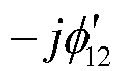
- The following clearly and completely describes the technical solutions in the embodiments of the present invention with reference to the accompanying drawings in the embodiments of the present invention. Apparently, the described embodiments are merely some rather than all of the embodiments of the present invention.
-
FIG. 3 is a flowchart of a signal decoding method according toEmbodiment 1 of the present invention. - The signal decoding method provided in this embodiment is applied to a MIMO system, the MIMO system includes a signal transmit end and a signal receive end, the signal receive end includes a first antenna and a second antenna, and the signal transmit end includes a third antenna and a fourth antenna.
- The method includes the following steps.
- Step S101: Obtain a first signal received by the first antenna and a second signal received by the second antenna, where the first signal and the second signal are from the third antenna and the fourth antenna of the signal transmit end.
- The MIMO system in this embodiment is a 2×2 transceiver system, to be specific, the signal receive end has two antennas: the first antenna and the second antenna, and the signal transmit end has two antennas: the third antenna and the fourth antenna.
- At the signal transmit end, two different signals are obtained after serial-to-parallel conversion is performed on a signal s, and are a transmit signal s 1 and a transmit signal s 2. After orthogonal space-time coding, in a first timeslot, the third antenna transmits the signal s 1, and the fourth antenna transmits the signal s 2; in a second timeslot, the third antenna transmits a signal -s 2 *, and the fourth antenna transmits a signal s 1 * ("*" represents a conjugate complex number). The signal s 1 and the signal -s 2 * transmitted by the third antenna are referred to as a first transmitted signal, and a signal s 2 and a signal s 1* transmitted by the fourth antenna are referred to as a second transmitted signal. At the signal receive end, in the first timeslot, the first antenna receives a signal y 1, and the second antenna receives a signal y 2 ; in the second timeslot, the first antenna receives a
signal 
signal 
signal 
signal 
- Step S102: Calculate a decoding coefficient by using a channel fading coefficient and a phase noise coefficient that are obtained by performing channel estimation based on the first signal and the second signal.
- Four channels are formed between the two antennas of the signal transmit end and the two antennas of the signal receive end. When a signal is transmitted from the signal transmit end to the signal receive end, because the signal fades due to signal scattering and reflection, a signal received by the signal receive end is not obtained simply through superposition of transmitted signals of the signal transmit end. To recover the signal transmitted by the signal transmit end, a signal fading degree needs to be calculated, so as to compensate for the received first signal and second signal in a decoding process. The signal fading degree is usually indicated by the channel fading coefficient, and the channel fading coefficient is obtained through channel estimation. In this embodiment, there are four channel fading coefficients that respectively belong to the four channels formed between the first antenna, the second antenna, the third antenna, and the fourth antenna. In the prior art, after a channel fading coefficient is obtained, a decoding parameter is obtained by using the channel fading coefficient, so as to decode the first signal and the second signal to obtain the transmit signal s 1 and the transmit signal s 2.
- However, for a radio wave with a relatively short wavelength and a relatively high frequency, a signal received by the signal receive end is affected by attenuation and also by phase noises of the signal transmit end and phase noises of the signal receive end. Because the signal transmit end includes two antennas, and the signal receive end includes two antennas, the phase noises also have four values that respectively correspond to the four antennas. In addition, usually, the phase noises of the signal transmit end and the phase noises of the signal receive end are mutually independent of each other.
- For the decoding parameter in the prior art, only the channel fading coefficient is considered, and no phase noise coefficient is considered. Consequently, the signal s 1 and the signal s 2 that are obtained through decoding interfere with each other, and decoding performance is relatively poor. In this embodiment, for the decoding parameter, not only the channel fading coefficient is considered, but also a phase noise coefficient of the signal transmit end and a phase noise coefficient of the signal receive end are considered. Same as the channel fading coefficient, the phase noise coefficient may also be obtained through channel estimation. Specifically, in an implementation process, the channel fading coefficient and the phase noise coefficient may be obtained by performing channel estimation once, to be specific, a phase noise is used as a part of a channel. During channel estimation, the channel fading coefficient and the phase noise coefficient are calculated as a whole. If a channel whose phase noise is not considered is H, a channel whose phase noise is considered is Hejϕ. Then the channel fading coefficient and the phase noise coefficient are used as a whole to obtain the decoding coefficient. It should be noted that, if the phase noise is considered in the channel, because the phase noise changes dynamically over time, the channel also dynamically changes, and the decoding coefficient obtained through calculation also dynamically changes. If a training-based channel estimation method, the signal transmit end needs to periodically send a training sequence to perform channel estimation, to obtain a decoding coefficient corresponding to the training sequence, and when the first signal and the second signal are not received signals corresponding to the training sequence, decoding coefficients respectively corresponding to the first signal and the second signal need to be estimated through an interpolation or in another manner. For example, it is assumed that a start time point of a time period T is tl, a corresponding decoding coefficient is m1, an end time point is t2, and a corresponding decoding coefficient is m2. If a receiving time of the first signal and the second signal is t3 and t2>t3>tl, a corresponding decoding coefficient m3 may be equal to m1+(m2-m1)(t3-t1)/(t2-t1).
- Alternatively, the channel fading coefficient and the phase noise coefficient may be obtained by performing channel estimation twice, to be specific, the channel fading coefficient is obtained by performing channel estimation for a first time, and the phase noise coefficient is obtained by performing channel estimation for a second time. Compared with channel estimation performed once, performing channel estimation twice can greatly reduce a workload of channel estimation performed for a single time, thereby improving decoding efficiency. For example, if the training-based channel estimation method is used, when channel estimation is performed once, a length of a training sequence for the channel estimation is L+1 (L is a channel impulse response length, and L is greater than 1 when channel equalization is not performed). During the channel estimation performed twice, channel fading and a phase noise are separated. Because the channel fading coefficient is a relatively stable parameter, channel estimation may be performed at a very long interval. For estimation of the phase noise coefficient, when channel equalization is performed, a channel impulse response length is 1, a length of a required training sequence is 1+1=2, and is less than a length of a training sequence required for performing channel estimation once, and therefore, a calculation amount of the channel estimation performed twice is much less. The channel estimation performed twice is described in detail in the following embodiment, and details are not described herein.
- Step S103: Decode the first signal and the second signal by using the decoding coefficient, to respectively obtain a first decoded signal and a second decoded signal.
- After the channel fading coefficient and the phase noise coefficient are obtained through channel estimation, the decoding parameter is obtained based on the channel fading coefficient and the phase noise coefficient, and the first signal and the second signal are decoded by using the decoding parameter to obtain the first decoded signal and the second decoded signal. The first decoded signal is related only to the transmit signal s 1 corresponding to the third antenna and is unrelated to the transmit signal s 2 corresponding to the fourth antenna, and the second decoded signal is related only to the transmit signal s 1 corresponding to the fourth antenna and is unrelated to the transmit signal s 2 corresponding to the third antenna. It may be learned from
FIG. 1 that the transmit signal s 1 and the transmit signal s 2 are signals before space-time coding, and after space-time coding is performed, a signal transmitted by the third antenna is a first transmitted signal, and a signal transmitted by the fourth antenna is a second transmitted signal. - In this embodiment, in a process of solving the decoding coefficient, the channel fading coefficient is obtained by considering channel fading, the phase noise coefficient is obtained by considering the phase noises of the signal transmit end and the phase noises of the signal receive end, and then the first signal and the second signal are decoded by using the decoding parameter obtained based on the channel fading coefficient and the phase noise coefficient. An obtained decoded signal is a signal not interfered with by another signal, thereby achieving a good decoding effect.
-
FIG. 4 is a flowchart of a signal decoding method according toEmbodiment 2 of the present invention. - The signal decoding method provided in this embodiment includes the following steps.
- Step S201: Obtain a first signal received by a first antenna and a second signal received by a second antenna, where the first signal and the second signal are from a third antenna and a fourth antenna of a signal transmit end.
- Because step S201 is the same as step S101 in
Embodiment 1, details are not described herein again. - Step S202: Calculate an equalization coefficient by using a channel fading coefficient obtained by performing channel estimation based on the first signal and the second signal.
- To improve decoding efficiency, channel estimation is performed twice in this embodiment, the channel fading coefficient is obtained by performing channel estimation for a first time, and a phase noise coefficient is obtained by performing channel estimation for a second time. It is assumed that channel fading coefficients obtained by performing channel estimation for a first time are h 11, h 12, h 21, and h 22. h 11 is a channel fading coefficient from the third antenna to the first antenna, h 12 is a channel fading coefficient from the fourth antenna to the first antenna, h 21 is a channel fading coefficient from the third antenna to the second antenna, and h 22 is a channel fading coefficient from the fourth antenna to the second antenna.
- Step S203: Perform equalization processing on the first signal and the second signal by using the equalization coefficient.
- Because channel fading exists in a process of transmitting a transmit signal on four channels between the first antenna and the fourth antenna, in this embodiment, the channel fading coefficient obtained through channel estimation is used to obtain the equalization coefficient, and equalization processing is performed on the first signal and the second signal by using the equalization coefficient, to cancel impact of channel fading on the transmit signal. In this way, only a phase noise needs to be considered when channel estimation is performed for a second time, so as to reduce a workload of channel estimation.
- Referring to
FIG. 5 , a specific equalization processing process may include the following:
The first signal and the second signal are first preprocessed to obtain a first group of four signals and a second group of four signals, where the first group of four signals and the second group of four signals each include a first timeslot of the first signal, a conjugate of a second timeslot of the first signal, the first timeslot of the second signal, and a conjugate of the second timeslot of the second signal. In practical application, to obtain the first group of four signals and the second group of four signals, serial-to-parallel conversion may be performed twice on each of the first signal and the second signal, to obtain the first timeslot and the second timeslot of the first signal in the two groups of four signals, and the first timeslot and the second timeslot of the second signal, and then conjugation is performed on the second timeslot of the first signal and the second timeslot of the second signal in the two groups of four signals. - The equalization processing is filtering the two groups of four signals by using the equalization coefficient. The equalization processing step may be performed in time domain, or may be performed in frequency domain. If equalization processing is performed in time domain, the equalization coefficient is a time-domain equalization coefficient, and if equalization processing is performed in frequency domain, the equalization coefficient is a frequency-domain equalization coefficient. Because the first signal and the second signal are time-domain signals, equalization processing only needs to be directly performed in time domain. The equalization processing is performing convolution on the two groups of four time-domain signals by using the equalization coefficient. However, if equalization processing is performed in frequency domain, the first signal and the second signal need to be converted from time-domain signals into frequency-domain signals, and then equalization processing is performed. In this case, the equalization processing means that the two groups of four signals are multiplied by using the equalization coefficient, and then signals obtained after equalization processing are converted into time-domain signals, so as to ensure that decoding in step S204 is performed in time domain. For brevity, the following formula for equalization processing is performed in time domain. Equalization processing may be performed in frequency domain with reference to these formulas.
- An equalization coefficient corresponding to the first group of four signals is a first group of equalization coefficients, and the first group of equalization coefficients include a first equalization coefficient W 11, a second equalization coefficient W 12, a third equalization coefficient W 13, and a fourth equalization coefficient W 14. The first timeslot of the first signal is filtered by using the first equalization coefficient W 11, the second timeslot of the first signal is filtered by using the second equalization coefficient W 12, the first timeslot of the second signal is filtered by using the third equalization coefficient W 13, and the second timeslot of the second signal is filtered by using the fourth equalization coefficient W 14.
- An equalization coefficient corresponding to the second group of four signals is a second group of equalization coefficients, and the second group of equalization coefficients include a fifth equalization coefficient W 21, a sixth equalization coefficient W 22, a seventh equalization coefficient W 23, and an eighth equalization coefficient W 24. The first timeslot of the first signal is filtered by using the fifth equalization coefficient W 21, the second timeslot of the first signal is filtered by using the sixth equalization coefficient W 22, the first timeslot of the second signal is filtered by using the seventh equalization coefficient W 23, and the second timeslot of the second signal is filtered by using the eighth equalization coefficient W 24.
- Because an objective of equalization processing is to cancel impact of channel fading, the equalization coefficient needs to meet the condition.
- In a possible implementation, the first
equalization coefficient 
equalization coefficient 
equalization coefficient 
equalization coefficient 
- In a possible implementation, the fifth
equalization coefficient 
equalization coefficient 
equalization coefficient 
equalization coefficient 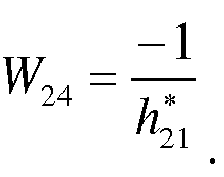
- h 11 is a channel fading coefficient from the third antenna to the first antenna, h 12 is a channel fading coefficient from the fourth antenna to the first antenna, h 21 is a channel fading coefficient from the third antenna to the second antenna, and h 22 is a channel fading coefficient from the fourth antenna to the second antenna.


- It should be noted that a MIMO system with dual-antenna transmission and dual-antenna receiving in this embodiment has the following features: The first antenna is relatively close to the second antenna, and the third antenna is relatively close to the fourth antenna. Therefore, the four channels formed between the first antenna and the fourth antenna are consistent in frequency selective fading, and are different in flat fading. Therefore, there is a proportional relationship between h 11 and h 12, and this may be specifically represented by h 12 = αh 11. There is also a proportional relationship between h 21 and h 12, and this may be specifically represented by h 21 = βh 22.
- After equalization processing, a third signal and a fourth signal that correspond to the first group of four signals, and a fifth signal and a sixth signal that correspond to the second group of four signals are obtained.
- The third signal includes the first timeslot ŷ 1 and the second timeslot


- A 1 = e jϕ
11 , A 2 = αe jϕ12 ,

- B 1 = e jϕ
21 ,


- The following result may be obtained by using the formula (13) to the formula (16):

- The fifth signal includes the first timeslot ỹ 1 and the second timeslot


-

12 ,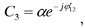

- D 1 = βe jϕ
21 , D 2 = e jϕ22 ,

- The following result may be obtained by using the formula (17) to the formula (20):

- ϕ 11 = ϕ tx1 + ϕ rx1, ϕ 12 = ϕ tx2 + ϕ rx1,
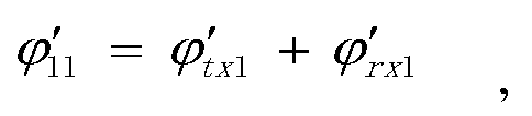


- Step S204: Calculate a decoding coefficient by using a phase noise coefficient obtained by performing channel estimation on a signal obtained after equalization processing.
- Equalization processing is performed on the first signal and the second signal in this embodiment to cancel interference caused to a transmitted signal of the signal transmit end by the four channels between the first antenna and the fourth antenna. If the third signal is considered as a signal received by the first antenna of the signal receive end, and the fourth signal is considered as a signal received by the second antenna, the four channels between the first antenna and the fourth antenna can be considered as flat channels, in other words, channels without fading. Likewise, if the fifth signal is considered as a signal received by the first antenna, the sixth signal is considered as a signal received by the second antenna, and the four channels between the first antenna and the fourth antenna may also be considered as channels without intercode interference.
- In this embodiment, channel estimation is performed on a signal obtained after equalization processing, so as to obtain a phase noise coefficient. Specifically, channel estimation is performed based on the third signal and the fourth signal to obtain a first group of phase noise coefficients, to be specific, phase noise coefficients in phase noise matrices H 1 and H 2. Channel estimation is performed based on the fifth signal and the sixth signal to obtain a second group of phase noise coefficients, to be specific, phase noise coefficients in phase noise matrices H 3 and H 4.
- In this embodiment, after the phase noise coefficient is obtained, a decoding coefficient is obtained based on the phase noise coefficient. The decoding coefficient is used for decoding, so that a signal obtained through decoding is related only to the transmit signal s 1 or the transmit signal s 2.
- Specifically, a first group of decoding coefficients are calculated based on the first group of phase noise coefficients, and the first group of decoding coefficients include a first decoding coefficient W 11, a second decoding coefficient W 12, a third decoding coefficient W 13, and a fourth decoding coefficient W 14 .
- It can be learned from the foregoing that the first decoding coefficient needs to meet a condition that a first decoded signal obtained through decoding is related only to the transmit signal s 1 corresponding to the third antenna.
- In a first possible implementation,

12 ,
22 . - In a second possible implementation,

12 ,

- In a third possible implementation,



- A second group of decoding coefficients are calculated based on the second group of phase noise coefficients, and the second group of decoding coefficients include a fifth decoding coefficient W 21, a sixth decoding coefficient W 22, a seventh decoding coefficient W 23, and an eighth decoding coefficient W 24.
- It can be learned from the foregoing that the second decoding coefficient needs to meet a condition that a second decoded signal obtained through decoding is related only to the transmit signal s 2 corresponding to the fourth antenna.
- In a first possible implementation,

12 ,
21 . - In a second possible implementation,


21 . - In a third possible implementation,


- Certainly, it may be understood that the foregoing three possible implementations of the first decoding coefficient to the eighth decoding coefficient do not constitute a limitation on the present invention.
- Step S205: Decode, by using the decoding parameter, the signal obtained after equalization processing, to obtain a transmit signal corresponding to the third antenna and a transmit signal corresponding to the fourth antenna.
- In this embodiment, after the first group of decoding coefficients are obtained, the third signal is decoded by using the first group of decoding coefficients. A specific decoding process may be: multiplying the first timeslot of the third signal and the first decoding coefficient, multiplying the second timeslot of the third signal and the second decoding coefficient, multiplying the first timeslot of the fourth signal and the third decoding coefficient, multiplying the second timeslot of the fourth signal and the fourth decoding coefficient, and adding multiplying results to each other to obtain the first decoded signal ŝ 1.
- After the second group of decoding coefficients are obtained, the fourth signal is decoded by using the second group of decoding coefficients. A specific decoding process may be: multiplying the first timeslot of the fifth signal and the fifth decoding coefficient, multiplying the second timeslot of the fifth signal and the sixth decoding coefficient, multiplying the first timeslot of the sixth signal and the seventh decoding coefficient, multiplying the second timeslot of the sixth signal and the eighth decoding coefficient, and adding multiplying results to each other to obtain the second decoded signal ŝ 2.
- For the first decoded signal ŝ 1, specifically, a formula (21) may be obtained with reference to the formula (13) to the formula (16) and the first implementation of the first group of decoding coefficients:

- A formula (22) may be obtained with reference to the formula (13) to the formula (16) and the second implementation of the first group of decoding coefficients:

- A formula (23) may be obtained with reference to the formula (13) to the formula (16) and the third implementation of the first group of decoding coefficients:

- It can be learned from the formula (21) to the formula (23) that the first decoded signal ŝ 1 is related only to the transmit signal s 1 corresponding to the third antenna, and is not interfered with by the transmit signal s 2, and a good decoding result is obtained.
- For the second decoded signal ŝ 2, specifically, a formula (24) may be obtained with reference to the formula (17) to the formula (20) and the first implementation of the second group of decoding coefficients:

- A formula (25) may be obtained with reference to the formula (17) to the formula (20) and the second implementation of the second group of decoding coefficients:

- A formula (26) may be obtained with reference to the formula (17) to the formula (20) and the third implementation of the second group of decoding coefficients:

- It can be learned from the formula (24) to the formula (26) that the second decoded signal ŝ 2 is related only to the transmit signal ŝ 2 corresponding to the fourth antenna, and is not interfered with by the transmit signal ŝ 1, and a good decoding result is obtained.
- In this embodiment, the channel fading coefficient is obtained by performing channel estimation for a first time, and the equalization coefficient is obtained based on the channel fading coefficient, so as to perform equalization processing on the first signal and the second signal to obtain the third signal and the fourth signal. After equalization processing is performed, channel estimation is performed for a second time based on the third signal and the fourth signal to obtain the decoding coefficient, and the first signal and the second signal are decoded by using the decoding coefficient, to respectively obtain the first decoded signal and the second decoded signal. A channel corresponding to the third signal and a channel corresponding to the fourth signal may be considered as channels without intercode interference, thereby improving decoding efficiency.
- It may be understood that, for channel estimation methods used for channel estimation performed twice, refer to the prior art. The methods are not specifically limited in the present invention.
- In addition, channel estimation performed for a second time is to obtain a phase noise coefficient. Because a phase noise coefficient dynamically changes, if a training-based channel estimation method is used, after a phase noise coefficient corresponding to a training sequence is obtained, an actual phase noise coefficient corresponding to the signal (the third signal and the fourth signal) may be obtained through an interpolation.
-
FIG. 6 is a structural block diagram of a signal decoding apparatus according to Embodiment 3 of the present invention. - The signal decoding apparatus provided in this embodiment is applied to a MIMO system, the MIMO system includes a signal transmit end and a signal receive end, the signal receive end includes a first antenna and a second antenna, and the signal transmit end includes a third antenna and a fourth antenna.
- The apparatus includes:
asignal obtaining unit 11, a decodingcoefficient calculation unit 21, and adecoding unit 31. - The
signal obtaining unit 11 is configured to obtain a first signal received by the first antenna and a second signal received by the second antenna, where the first signal and the second signal are from the third antenna and the fourth antenna of the signal transmit end. - The decoding
coefficient calculation unit 21 is configured to calculate a decoding coefficient by using a channel fading coefficient and a phase noise coefficient that are obtained by performing channel estimation based on the first signal and the second signal, where the channel fading coefficient includes channel fading coefficients respectively corresponding to four channels formed between the first antenna, the second antenna, the third antenna, and the fourth antenna, the phase noise coefficient includes a phase noise coefficient of the signal transmit end and a phase noise coefficient of the signal receive end, and a phase noise corresponding to the phase noise coefficient of the signal transmit end and a phase noise corresponding to the phase noise coefficient of the signal receive end are independent of each other. - The
decoding unit 31 is configured to decode the first signal and the second signal by using the decoding coefficient, to respectively obtain a first decoded signal and a second decoded signal, where the first decoded signal is related only to a transmit signal corresponding to the third antenna and is unrelated to a transmit signal corresponding to the fourth antenna, and the second decoded signal is related only to the transmit signal corresponding to the fourth antenna and is unrelated to the transmit signal corresponding to the third antenna. - In this embodiment, in a process of solving the decoding coefficient, the channel fading coefficient is obtained by considering channel fading, the phase noise coefficient is obtained by considering the phase noises of the signal transmit end and the phase noises of the signal receive end, and then the first signal and the second signal are decoded by using the decoding parameter obtained based on the channel fading coefficient and the phase noise coefficient. An obtained decoded signal is a signal not interfered with by another signal, thereby achieving a good decoding effect.
- In a specific implementation process of the decoding
coefficient calculation unit 21, the channel fading coefficient and the phase noise coefficient may be obtained by performing channel estimation once, to be specific, during channel estimation, the channel fading coefficient and the phase noise coefficient are calculated as a whole. Then the channel fading coefficient and the phase noise coefficient are used as a whole to obtain the decoding coefficient. Alternatively, the channel fading coefficient and the phase noise coefficient may be obtained by performing channel estimation twice, to be specific, the channel fading coefficient is obtained by performing channel estimation for a first time, and the phase noise coefficient is obtained by performing channel estimation for a second time. - If the channel fading coefficient and the phase noise coefficient are obtained by performing channel estimation twice, the decoding
coefficient calculation unit 21 specifically includes:
an equalizationcoefficient calculation unit 211, anequalization unit 212, and a decodingcoefficient calculation subunit 213. - The equalization
coefficient calculation unit 211 is configured to calculate an equalization coefficient by using the channel fading coefficient obtained by performing channel estimation based on the first signal and the second signal. - The
equalization unit 212 is configured to perform equalization processing on the first signal and the second signal by using the equalization coefficient. - The decoding
coefficient calculation subunit 213 is configured to calculate the decoding coefficient by using the phase noise coefficient obtained by performing channel estimation on a signal obtained after equalization processing. - If the first signal and the second signal correspond to a same timeslot, and the timeslot includes a first timeslot and a second timeslot, the equalization
coefficient calculation unit 211 is specifically configured to calculate a first group of equalization coefficients and a second group of equalization coefficients by using the channel fading coefficient obtained by performing channel estimation based on the first signal and the second signal. - The
equalization unit 212 specifically includes a preprocessing unit and a filter unit, and the filter unit includes a first filter unit and a second filter unit. - The preprocessing unit is configured to preprocess the first signal and the second signal to obtain a first group of four signals and a second group of four signals, where the first group of four signals and the second group of four signals each include the first timeslot of the first signal, a conjugate of the second timeslot of the first signal, the first timeslot of the second signal, and a conjugate of the second timeslot of the second signal.
- The first filter unit is configured to filter the first group of four signals by using the first group of equalization coefficients to obtain a third signal and a fourth signal, where the third signal and the fourth signal each correspond to the timeslot.
- The second filter unit is configured to filter the second group of four signals by using the second group of equalization coefficients to obtain a fifth signal and a sixth signal, where the fifth signal and the sixth signal each correspond to the timeslot.
- If the first group of equalization coefficients include a first equalization coefficient, a second equalization coefficient, a third equalization coefficient, and a fourth equalization coefficient, the first filter unit is specifically configured to:
- filter the first timeslot of the first signal by using the first equalization coefficient, to obtain the first timeslot of the third signal;
- filter the conjugate of the second timeslot of the first signal by using the second equalization coefficient, to obtain the second timeslot of the third signal;
- filter the first timeslot of the second signal by using the third equalization coefficient, to obtain the first timeslot of the fourth signal; and
- filter the conjugate of the second timeslot of the second signal by using the fourth equalization coefficient, to obtain the second timeslot of the fourth signal.
- If the second group of equalization coefficients include a fifth equalization coefficient, a sixth equalization coefficient, a seventh equalization coefficient, and an eighth equalization coefficient, the second filter unit is specifically configured to:
- filter the first timeslot of the first signal by using the fifth equalization coefficient, to obtain the first timeslot of the fifth signal;
- filter the conjugate of the second timeslot of the first signal by using the sixth equalization coefficient, to obtain the second timeslot of the fifth signal;
- filter the first timeslot of the second signal by using the seventh equalization coefficient, to obtain the first timeslot of the sixth signal; and
- filter the conjugate of the second timeslot of the second signal by using the eighth equalization coefficient, to obtain the second timeslot of the sixth signal.
- The decoding
coefficient calculation subunit 213 may be specifically configured to: - calculate a first group of decoding coefficients by using a first group of phase noise coefficients obtained by performing channel estimation based on the third signal and the fourth signal; and
- calculate a second group of decoding coefficients by using a second group of phase noise coefficients obtained by performing channel estimation based on the fifth signal and the sixth signal.
- The
decoding unit 31 includes afirst decoding unit 311 and asecond decoding unit 312. - The
first decoding unit 311 is configured to:
decode the third signal and the fourth signal by using the first group of decoding coefficients, to obtain the first decoded signal. - The
second decoding unit 312 is configured to:
decode the fifth signal and the sixth signal by using the second group of decoding coefficients, to obtain the second decoded signal. - If the first group of decoding coefficients include a first decoding coefficient, a second decoding coefficient, a third decoding coefficient, and a fourth decoding coefficient, the
first decoding unit 311 is specifically configured to:
multiply the first timeslot of the third signal and the first decoding coefficient, multiply the second timeslot of the third signal and the second decoding coefficient, multiply the first timeslot of the fourth signal and the third decoding coefficient, multiply the second timeslot of the fourth signal and the fourth decoding coefficient, and add multiplying results to each other to obtain the first decoded signal. - If the second group of decoding coefficients include a fifth decoding coefficient, a sixth decoding coefficient, a seventh decoding coefficient, and an eighth decoding coefficient, the
second decoding unit 312 is specifically configured to:
multiply the first timeslot of the fifth signal and the fifth decoding coefficient, multiply the second timeslot of the fifth signal and the sixth decoding coefficient, multiply the first timeslot of the sixth signal and the seventh decoding coefficient, multiply the second timeslot of the sixth signal and the eighth decoding coefficient, and add multiplying results to each other to obtain the second decoded signal. - Optionally, the
equalization unit 212 is specifically configured to:
in time domain, perform equalization processing on the first signal and the second signal by using the equalization coefficient. - Optionally, the
equalization unit 212 is specifically configured to:
in frequency domain, perform equalization processing on the first signal and the second signal by using the equalization coefficient. - In practical application, the
equalization unit 212 may be implemented by using a filter, and may be specifically implemented by using a transverse filter. - Embodiment 4 of the present invention provides a signal decoding device, the device is applied to a MIMO system, the MIMO system includes a signal transmit end and a signal receive end, the signal receive end includes a first antenna and a second antenna, and the signal transmit end includes a third antenna and a fourth antenna.
- The device includes a memory and a processor, the memory is configured to store a group of program instructions, and the processor is configured to invoke the program instructions stored in the memory, to perform the following operations:
- obtaining a first signal received by the first antenna and a second signal received by the second antenna, where the first signal and the second signal are from the third antenna and the fourth antenna of the signal transmit end;
- calculating a decoding coefficient by using a channel fading coefficient and a phase noise coefficient that are obtained by performing channel estimation based on the first signal and the second signal, where the channel fading coefficient includes channel fading coefficients respectively corresponding to four channels formed between the first antenna, the second antenna, the third antenna, and the fourth antenna, the phase noise coefficient includes a phase noise coefficient of the signal transmit end and a phase noise coefficient of the signal receive end, and a phase noise corresponding to the phase noise coefficient of the signal transmit end and a phase noise corresponding to the phase noise coefficient of the signal receive end are independent of each other; and
- decoding the first signal and the second signal by using the decoding coefficient, to respectively obtain a first decoded signal and a second decoded signal, where the first decoded signal is related only to a transmit signal corresponding to the third antenna and is unrelated to a transmit signal corresponding to the fourth antenna, the second decoded signal is related only to the transmit signal corresponding to the fourth antenna and is unrelated to the transmit signal corresponding to the third antenna, and the transmit signal is a signal before encoding.
- Optionally, the processor may be a central processing unit (Central Processing Unit, CPU), and the memory may be an internal memory of a random access memory (Random Access Memory, RAM) type. The processor and the memory may be integrated into one or more independent circuits or hardware, for example, an application-specific integrated circuit (Application-Specific Integrated Circuit, ASIC).
- A person of ordinary skill in the art may understand that all or some of the steps of the method embodiments may be implemented by a program instructing relevant hardware. The program may be stored in a computer readable storage medium. When the program runs, the steps of the method embodiments are performed. The storage medium may be at least one of the following media: media that are capable of storing program code, such as a read-only memory (English: read-only memory, ROM for short), a RAM, a magnetic disk, or an optical disc.
- It should be noted that the embodiments in this specification are all described in a progressive manner, for same or similar parts in the embodiments, refer to these embodiments, and each embodiment focuses on a difference from other embodiments. Especially, device and system embodiments are basically similar to a method embodiment, and therefore are described briefly. For related parts, refer to partial descriptions in the method embodiment. The described device and system embodiments are merely examples. The units described as separate parts may or may not be physically separate, and parts displayed as units may or may not be physical units, may be located in one position, or may be distributed on a plurality of network units. Some or all of the modules may be selected based on actual needs to achieve the objectives of the solutions of the embodiments. A person of ordinary skill in the art may understand and implement the embodiments of the present invention without creative efforts.
- The foregoing descriptions are merely examples of specific implementations of the present invention, but are not intended to limit the protection scope of the present invention. Any variation or replacement readily figured out by a person skilled in the art within the technical scope disclosed in the present invention shall fall within the protection scope of the present invention. Therefore, the protection scope of the present invention shall be subject to the protection scope of the claims.
Claims (13)
- A signal decoding method, wherein the method is applied to a Multiple-Input Multiple-Output, MIMO, system, the MIMO system comprises a signal transmit end and a signal receive end, the signal receive end comprises a first antenna and a second antenna, and the signal transmit end comprises a third antenna and a fourth antenna; and
the method comprises:obtaining (S101) a first signal received by the first antenna and a second signal received by the second antenna, wherein the first signal and the second signal are from the third antenna and the fourth antenna of the signal transmit end;calculating (S102) a decoding coefficient by using a channel fading coefficient and a phase noise coefficient that are obtained by performing channel estimation based on the first signal and the second signal, wherein the channel fading coefficient comprises channel fading coefficients respectively corresponding to four channels formed between the first antenna, the second antenna, the third antenna, and the fourth antenna, and the phase noise coefficient comprises a phase noise coefficient of the signal transmit end and a phase noise coefficient of the signal receive end; anddecoding (S103) the first signal and the second signal by using the decoding coefficient, to respectively obtain a first decoded signal and a second decoded signal, wherein the first decoded signal is related only to a transmit signal corresponding to the third antenna and is unrelated to a transmit signal corresponding to the fourth antenna, the second decoded signal is related only to the transmit signal corresponding to the fourth antenna and is unrelated to the transmit signal corresponding to the third antenna, and the transmit signal is a signal before encoding;wherein the calculating a decoding coefficient by using a channel fading coefficient and a phase noise coefficient that are obtained by performing channel estimation based on the first signal and the second signal comprises:calculating (S202) an equalization coefficient by using the channel fading coefficient obtained by performing channel estimation for a first time based on the first signal and the second signal;performing (S203) equalization processing on the first signal and the second signal by using the equalization coefficient; andcalculating (S204) the decoding coefficient by using the phase noise coefficient obtained by performing channel estimation for a second time on a signal obtained after equalization processing, wherein the performing channel estimation for a first time for obtaining the channel fading coefficient is performed at a longer interval than the performing channel estimation for a second time for obtaining the phase noise coefficient. - The method according to claim 1, wherein the first signal and the second signal correspond to a same timeslot, and the timeslot comprises a first timeslot and a second timeslot;
the calculating an equalization coefficient by using the channel fading coefficient obtained by performing channel estimation based on the first signal and the second signal comprises:calculating a first group of equalization coefficients and a second group of equalization coefficients by using the channel fading coefficient obtained by performing channel estimation based on the first signal and the second signal; andthe performing equalization processing on the first signal and the second signal by using the equalization coefficient comprises:preprocessing the first signal and the second signal to obtain a first group of four signals and a second group of four signals, wherein the first group of four signals and the second group of four signals each comprise the first timeslot of the first signal, a conjugate of the second timeslot of the first signal, the first timeslot of the second signal, and a conjugate of the second timeslot of the second signal;filtering the first group of four signals by using the first group of equalization coefficients to obtain a third signal and a fourth signal, wherein the third signal and the fourth signal each correspond to the timeslot; andfiltering the second group of four signals by using the second group of equalization coefficients to obtain a fifth signal and a sixth signal, wherein the fifth signal and the sixth signal each correspond to the timeslot. - The method according to claim 2, wherein the first group of equalization coefficients comprise a first equalization coefficient, a second equalization coefficient, a third equalization coefficient, and a fourth equalization coefficient; and
the filtering the first group of four signals by using the first group of equalization coefficients to obtain a third signal and a fourth signal comprises:filtering the first timeslot of the first signal by using the first equalization coefficient, to obtain the first timeslot of the third signal;filtering the conjugate of the second timeslot of the first signal by using the second equalization coefficient, to obtain the second timeslot of the third signal;filtering the first timeslot of the second signal by using the third equalization coefficient, to obtain the first timeslot of the fourth signal; andfiltering the conjugate of the second timeslot of the second signal by using the fourth equalization coefficient, to obtain the second timeslot of the fourth signal. - The method according to claim 2, wherein the second group of equalization coefficients comprise a fifth equalization coefficient, a sixth equalization coefficient, a seventh equalization coefficient, and an eighth equalization coefficient; and
the filtering the second group of four signals by using the second group of equalization coefficients to obtain a fifth signal and a sixth signal comprises:filtering the first timeslot of the first signal by using the fifth equalization coefficient, to obtain the first timeslot of the fifth signal;filtering the conjugate of the second timeslot of the first signal by using the sixth equalization coefficient, to obtain the second timeslot of the fifth signal;filtering the first timeslot of the second signal by using the seventh equalization coefficient, to obtain the first timeslot of the sixth signal; andfiltering the conjugate of the second timeslot of the second signal by using the eighth equalization coefficient, to obtain the second timeslot of the sixth signal. - The method according to claim 1, wherein the performing equalization processing on the first signal and the second signal by using the equalization coefficient comprises:
in time domain, performing equalization processing on the first signal and the second signal by using the equalization coefficient. - The method according to claim 1, wherein the performing equalization processing on the first signal and the second signal by using the equalization coefficient comprises:
in frequency domain, performing equalization processing on the first signal and the second signal by using the equalization coefficient. - A signal decoding apparatus, wherein the apparatus is applied to a Multiple-Input Multiple-Output, MIMO, system, the MIMO system comprises a signal transmit end and a signal receive end, the signal receive end comprises a first antenna and a second antenna, and the signal transmit end comprises a third antenna and a fourth antenna; and
the apparatus comprises:a signal obtaining unit (11), a decoding coefficient calculation unit (21), and a decoding unit (31), whereinthe signal obtaining unit (11) is configured to obtain a first signal received by the first antenna and a second signal received by the second antenna, wherein the first signal and the second signal are from the third antenna and the fourth antenna of the signal transmit end;the decoding coefficient calculation unit (21) is configured to calculate a decoding coefficient by using a channel fading coefficient and a phase noise coefficient that are obtained by performing channel estimation based on the first signal and the second signal, wherein the channel fading coefficient comprises channel fading coefficients respectively corresponding to four channels formed between the first antenna, the second antenna, the third antenna, and the fourth antenna, and the phase noise coefficient comprises a phase noise coefficient of the signal transmit end and a phase noise coefficient of the signal receive end; andthe decoding unit (31) is configured to decode the first signal and the second signal by using the decoding coefficient, to respectively obtain a first decoded signal and a second decoded signal, wherein the first decoded signal is related only to a transmit signal corresponding to the third antenna and is unrelated to a transmit signal corresponding to the fourth antenna, the second decoded signal is related only to the transmit signal corresponding to the fourth antenna and is unrelated to the transmit signal corresponding to the third antenna, and the transmit signal is a signal before encoding;wherein the decoding coefficient calculation unit (21) specifically comprises:an equalization coefficient calculation unit (211), an equalization unit (212), and a decoding coefficient calculation subunit (213), whereinthe equalization coefficient calculation unit (211) is configured to calculate an equalization coefficient by using the channel fading coefficient obtained by performing channel estimation for a first time based on the first signal and the second signal;the equalization unit (212) is configured to perform equalization processing on the first signal and the second signal by using the equalization coefficient; andthe decoding coefficient calculation subunit (213) is configured to calculate the decoding coefficient by using the phase noise coefficient obtained by performing channel estimation for a second time on a signal obtained after equalization processing, wherein the performing channel estimation for a first time for obtaining the channel fading coefficient is performed at a longer interval than the performing channel estimation for a second time for obtaining the phase noise coefficient. - The apparatus according to claim 7, wherein the first signal and the second signal correspond to a same timeslot, and the timeslot comprises a first timeslot and a second timeslot;
the equalization coefficient calculation unit (211) is specifically configured to calculate a first group of equalization coefficients and a second group of equalization coefficients by using the channel fading coefficient obtained by performing channel estimation based on the first signal and the second signal; and
the equalization unit (212) specifically comprises a preprocessing unit and a filter unit, and the filter unit comprises a first filter unit and a second filter unit, wherein
the preprocessing unit is configured to preprocess the first signal and the second signal to obtain a first group of four signals and a second group of four signals, wherein the first group of four signals and the second group of four signals each comprise the first timeslot of the first signal, a conjugate of the second timeslot of the first signal, the first timeslot of the second signal, and a conjugate of the second timeslot of the second signal;
the first filter unit is configured to filter the first group of four signals by using the first group of equalization coefficients to obtain a third signal and a fourth signal, wherein the third signal and the fourth signal each correspond to the timeslot; and
the second filter unit is configured to filter the second group of four signals by using the second group of equalization coefficients to obtain a fifth signal and a sixth signal, wherein the fifth signal and the sixth signal each correspond to the timeslot. - The apparatus according to claim 8, wherein the first group of equalization coefficients comprise a first equalization coefficient, a second equalization coefficient, a third equalization coefficient, and a fourth equalization coefficient; and
the first filter unit is specifically configured to:filter the first timeslot of the first signal by using the first equalization coefficient, to obtain the first timeslot of the third signal;filter the conjugate of the second timeslot of the first signal by using the second equalization coefficient, to obtain the second timeslot of the third signal;filter the first timeslot of the second signal by using the third equalization coefficient, to obtain the first timeslot of the fourth signal; andfilter the conjugate of the second timeslot of the second signal by using the fourth equalization coefficient, to obtain the second timeslot of the fourth signal. - The apparatus according to claim 9, wherein the first equalization coefficient


h 11 is a channel fading coefficient from the third antenna to the first antenna,

- The apparatus according to claim 8, wherein the second group of equalization coefficients comprise a fifth equalization coefficient, a sixth equalization coefficient, a seventh equalization coefficient, and an eighth equalization coefficient; and
the second filter unit is specifically configured to:filter the first timeslot of the first signal by using the fifth equalization coefficient, to obtain the first timeslot of the fifth signal;filter the conjugate of the second timeslot of the first signal by using the sixth equalization coefficient, to obtain the second timeslot of the fifth signal;filter the first timeslot of the second signal by using the seventh equalization coefficient, to obtain the first timeslot of the sixth signal; andfilter the conjugate of the second timeslot of the second signal by using the eighth equalization coefficient, to obtain the second timeslot of the sixth signal. - The apparatus according to claim 7, wherein the equalization unit (212) is specifically configured to:
in time domain, perform equalization processing on the first signal and the second signal by using the equalization coefficient. - The apparatus according to claim 7, wherein the equalization unit (212) is specifically configured to:
in frequency domain, perform equalization processing on the first signal and the second signal by using the equalization coefficient.
Applications Claiming Priority (1)
| Application Number | Priority Date | Filing Date | Title |
|---|---|---|---|
| PCT/CN2016/090691 WO2018014253A1 (en) | 2016-07-20 | 2016-07-20 | Signal decoding method, apparatus and device |
Publications (3)
| Publication Number | Publication Date |
|---|---|
| EP3447933A1 EP3447933A1 (en) | 2019-02-27 |
| EP3447933A4 EP3447933A4 (en) | 2019-04-24 |
| EP3447933B1 true EP3447933B1 (en) | 2020-11-04 |
Family
ID=60992813
Family Applications (1)
| Application Number | Title | Priority Date | Filing Date |
|---|---|---|---|
| EP16909181.6A Active EP3447933B1 (en) | 2016-07-20 | 2016-07-20 | Signal decoding method, apparatus and device |
Country Status (4)
| Country | Link |
|---|---|
| EP (1) | EP3447933B1 (en) |
| CN (1) | CN108496310B (en) |
| MY (1) | MY190950A (en) |
| WO (1) | WO2018014253A1 (en) |
Families Citing this family (1)
| Publication number | Priority date | Publication date | Assignee | Title |
|---|---|---|---|---|
| CN108736938B (en) * | 2018-09-07 | 2021-01-22 | 电子科技大学 | Uplink channel estimation and data demodulation method for massive MIMO |
Family Cites Families (12)
| Publication number | Priority date | Publication date | Assignee | Title |
|---|---|---|---|---|
| US7366089B2 (en) * | 2003-10-08 | 2008-04-29 | Atheros Communications, Inc. | Apparatus and method of multiple antenna receiver combining of high data rate wideband packetized wireless communication signals |
| US7564917B2 (en) * | 2005-11-01 | 2009-07-21 | Intel Corporation | Multicarrier receiver and method for generating common phase error estimates for use in systems that employ two or more transmit antennas with independent local oscillators |
| CN101039136B (en) * | 2006-03-15 | 2011-09-14 | 华为技术有限公司 | Space-frequency coding-based multi-antenna transmitter diversity method and system thereof |
| CN101043297B (en) * | 2006-03-20 | 2010-08-25 | 华为技术有限公司 | A method and system for transmitting signals in multi-antenna communication |
| US7889822B2 (en) * | 2006-09-21 | 2011-02-15 | Broadcom Corporation | Frequency domain equalizer with one dominant interference cancellation for dual antenna radio |
| CN101136731B (en) * | 2007-08-09 | 2011-08-31 | 复旦大学 | Method for eliminating phase noise using continuous transmission parameter signalling |
| CN101437007A (en) * | 2007-11-12 | 2009-05-20 | 华为技术有限公司 | Method, apparatus and equipment for sending and receiving data of MIMO system |
| CN101488775B (en) * | 2008-01-18 | 2013-09-11 | 中兴通讯股份有限公司 | Space multiplexing method and apparatus in TD-SCDMA system |
| JP4561916B2 (en) * | 2008-10-31 | 2010-10-13 | ソニー株式会社 | Wireless communication apparatus and wireless communication method, signal processing apparatus and signal processing method, and computer program |
| US8416841B1 (en) * | 2009-11-23 | 2013-04-09 | Xilinx, Inc. | Multiple-input multiple-output (MIMO) decoding with subcarrier grouping |
| WO2015135132A1 (en) * | 2014-03-11 | 2015-09-17 | 华为技术有限公司 | Signal processing method and apparatus |
| CN105306118B (en) * | 2015-10-19 | 2018-08-21 | 东南大学 | The asynchronous adjustable multi-carrier wireless transmission method of wideband and system |
-
2016
- 2016-07-20 CN CN201680079903.0A patent/CN108496310B/en active Active
- 2016-07-20 EP EP16909181.6A patent/EP3447933B1/en active Active
- 2016-07-20 MY MYPI2018002122A patent/MY190950A/en unknown
- 2016-07-20 WO PCT/CN2016/090691 patent/WO2018014253A1/en not_active Ceased
Non-Patent Citations (1)
| Title |
|---|
| None * |
Also Published As
| Publication number | Publication date |
|---|---|
| EP3447933A1 (en) | 2019-02-27 |
| MY190950A (en) | 2022-05-23 |
| CN108496310B (en) | 2021-01-29 |
| CN108496310A (en) | 2018-09-04 |
| EP3447933A4 (en) | 2019-04-24 |
| WO2018014253A1 (en) | 2018-01-25 |
Similar Documents
| Publication | Publication Date | Title |
|---|---|---|
| CN100499395C (en) | Space-Time Transmit Diversity (STTD) for Multiple Antennas in Wireless Communications | |
| EP2568676B1 (en) | Pre-coding method, pre-decoding method, transmitter and mobile terminal based on interference alignment | |
| US9118372B2 (en) | Method and apparatus for downlink multiuser MIMO transmission in a wireless network | |
| EP3672095B1 (en) | Method and device for indicating and determining precoding matrix | |
| EP2602943B1 (en) | Interference alignment method and device and multiple-channel communication system | |
| CN103312389A (en) | Multiuser interference suppression method, terminal and base station | |
| CN102013904A (en) | Uplink data processing method and system | |
| CN114600384A (en) | A channel measurement method and communication device | |
| EP1349297A1 (en) | A closed loop multiple antenna system | |
| CN101986575B (en) | Precoding Method for Multi-user MIMO System | |
| EP2485423B1 (en) | Precoding method in cooperative relay system, communication apparatus and relay apparatus | |
| CN102171946A (en) | Method and device for data transmission | |
| CN103873125A (en) | Downlink signal sending method and downlink signal sending equipment in multiaerial system | |
| EP3447933A1 (en) | Signal decoding method, apparatus and device | |
| CN102055691A (en) | Estimation processing method for beamforming (BF) weight and base station | |
| US11303487B2 (en) | Wireless communication system, wireless communication method, and transmitting device | |
| CN101521531B (en) | Method of enhancing down-link performance of TD-LTE by antenna selection | |
| US9973247B2 (en) | Wireless communication system | |
| CN102957468A (en) | MU-MIMO (multi-user multiple-input multiple-output) user pairing method | |
| CN101958852B (en) | Method and device for estimating CINR of MLD receiver in MIMO system | |
| CN102148779B (en) | Method and device for detecting signals | |
| Jing et al. | Interference cancellation in distributed space-time coded wireless relay networks | |
| CN106603137A (en) | Method and device for combining antennas | |
| CN105187109B (en) | The residual interference removing method and multiple-input multiple-output broadcast of multiple-input multiple-output broadcast | |
| KR101205996B1 (en) | Method for transmitting/receiving video signal in two-way relaying system |
Legal Events
| Date | Code | Title | Description |
|---|---|---|---|
| STAA | Information on the status of an ep patent application or granted ep patent |
Free format text: STATUS: THE INTERNATIONAL PUBLICATION HAS BEEN MADE |
|
| PUAI | Public reference made under article 153(3) epc to a published international application that has entered the european phase |
Free format text: ORIGINAL CODE: 0009012 |
|
| STAA | Information on the status of an ep patent application or granted ep patent |
Free format text: STATUS: REQUEST FOR EXAMINATION WAS MADE |
|
| 17P | Request for examination filed |
Effective date: 20181122 |
|
| AK | Designated contracting states |
Kind code of ref document: A1 Designated state(s): AL AT BE BG CH CY CZ DE DK EE ES FI FR GB GR HR HU IE IS IT LI LT LU LV MC MK MT NL NO PL PT RO RS SE SI SK SM TR |
|
| AX | Request for extension of the european patent |
Extension state: BA ME |
|
| A4 | Supplementary search report drawn up and despatched |
Effective date: 20190327 |
|
| RIC1 | Information provided on ipc code assigned before grant |
Ipc: H04B 7/04 20170101AFI20190321BHEP Ipc: H04L 1/06 20060101ALI20190321BHEP Ipc: H04B 7/0413 20170101ALN20190321BHEP Ipc: H04B 7/08 20060101ALI20190321BHEP Ipc: H04B 7/06 20060101ALI20190321BHEP |
|
| DAV | Request for validation of the european patent (deleted) | ||
| DAX | Request for extension of the european patent (deleted) | ||
| STAA | Information on the status of an ep patent application or granted ep patent |
Free format text: STATUS: EXAMINATION IS IN PROGRESS |
|
| 17Q | First examination report despatched |
Effective date: 20191127 |
|
| GRAP | Despatch of communication of intention to grant a patent |
Free format text: ORIGINAL CODE: EPIDOSNIGR1 |
|
| STAA | Information on the status of an ep patent application or granted ep patent |
Free format text: STATUS: GRANT OF PATENT IS INTENDED |
|
| RIC1 | Information provided on ipc code assigned before grant |
Ipc: H04B 7/06 20060101ALI20200515BHEP Ipc: H04B 7/0413 20170101ALN20200515BHEP Ipc: H04L 1/06 20060101ALI20200515BHEP Ipc: H04B 7/04 20170101AFI20200515BHEP Ipc: H04B 7/08 20060101ALI20200515BHEP |
|
| INTG | Intention to grant announced |
Effective date: 20200605 |
|
| GRAS | Grant fee paid |
Free format text: ORIGINAL CODE: EPIDOSNIGR3 |
|
| GRAA | (expected) grant |
Free format text: ORIGINAL CODE: 0009210 |
|
| STAA | Information on the status of an ep patent application or granted ep patent |
Free format text: STATUS: THE PATENT HAS BEEN GRANTED |
|
| AK | Designated contracting states |
Kind code of ref document: B1 Designated state(s): AL AT BE BG CH CY CZ DE DK EE ES FI FR GB GR HR HU IE IS IT LI LT LU LV MC MK MT NL NO PL PT RO RS SE SI SK SM TR |
|
| REG | Reference to a national code |
Ref country code: GB Ref legal event code: FG4D |
|
| REG | Reference to a national code |
Ref country code: CH Ref legal event code: EP |
|
| REG | Reference to a national code |
Ref country code: AT Ref legal event code: REF Ref document number: 1332158 Country of ref document: AT Kind code of ref document: T Effective date: 20201115 |
|
| REG | Reference to a national code |
Ref country code: DE Ref legal event code: R096 Ref document number: 602016047507 Country of ref document: DE |
|
| REG | Reference to a national code |
Ref country code: IE Ref legal event code: FG4D |
|
| REG | Reference to a national code |
Ref country code: NL Ref legal event code: MP Effective date: 20201104 |
|
| REG | Reference to a national code |
Ref country code: AT Ref legal event code: MK05 Ref document number: 1332158 Country of ref document: AT Kind code of ref document: T Effective date: 20201104 |
|
| PG25 | Lapsed in a contracting state [announced via postgrant information from national office to epo] |
Ref country code: PT Free format text: LAPSE BECAUSE OF FAILURE TO SUBMIT A TRANSLATION OF THE DESCRIPTION OR TO PAY THE FEE WITHIN THE PRESCRIBED TIME-LIMIT Effective date: 20210304 Ref country code: RS Free format text: LAPSE BECAUSE OF FAILURE TO SUBMIT A TRANSLATION OF THE DESCRIPTION OR TO PAY THE FEE WITHIN THE PRESCRIBED TIME-LIMIT Effective date: 20201104 Ref country code: NO Free format text: LAPSE BECAUSE OF FAILURE TO SUBMIT A TRANSLATION OF THE DESCRIPTION OR TO PAY THE FEE WITHIN THE PRESCRIBED TIME-LIMIT Effective date: 20210204 Ref country code: FI Free format text: LAPSE BECAUSE OF FAILURE TO SUBMIT A TRANSLATION OF THE DESCRIPTION OR TO PAY THE FEE WITHIN THE PRESCRIBED TIME-LIMIT Effective date: 20201104 Ref country code: GR Free format text: LAPSE BECAUSE OF FAILURE TO SUBMIT A TRANSLATION OF THE DESCRIPTION OR TO PAY THE FEE WITHIN THE PRESCRIBED TIME-LIMIT Effective date: 20210205 |
|
| PG25 | Lapsed in a contracting state [announced via postgrant information from national office to epo] |
Ref country code: AT Free format text: LAPSE BECAUSE OF FAILURE TO SUBMIT A TRANSLATION OF THE DESCRIPTION OR TO PAY THE FEE WITHIN THE PRESCRIBED TIME-LIMIT Effective date: 20201104 Ref country code: ES Free format text: LAPSE BECAUSE OF FAILURE TO SUBMIT A TRANSLATION OF THE DESCRIPTION OR TO PAY THE FEE WITHIN THE PRESCRIBED TIME-LIMIT Effective date: 20201104 Ref country code: LV Free format text: LAPSE BECAUSE OF FAILURE TO SUBMIT A TRANSLATION OF THE DESCRIPTION OR TO PAY THE FEE WITHIN THE PRESCRIBED TIME-LIMIT Effective date: 20201104 Ref country code: IS Free format text: LAPSE BECAUSE OF FAILURE TO SUBMIT A TRANSLATION OF THE DESCRIPTION OR TO PAY THE FEE WITHIN THE PRESCRIBED TIME-LIMIT Effective date: 20210304 Ref country code: PL Free format text: LAPSE BECAUSE OF FAILURE TO SUBMIT A TRANSLATION OF THE DESCRIPTION OR TO PAY THE FEE WITHIN THE PRESCRIBED TIME-LIMIT Effective date: 20201104 Ref country code: BG Free format text: LAPSE BECAUSE OF FAILURE TO SUBMIT A TRANSLATION OF THE DESCRIPTION OR TO PAY THE FEE WITHIN THE PRESCRIBED TIME-LIMIT Effective date: 20210204 Ref country code: SE Free format text: LAPSE BECAUSE OF FAILURE TO SUBMIT A TRANSLATION OF THE DESCRIPTION OR TO PAY THE FEE WITHIN THE PRESCRIBED TIME-LIMIT Effective date: 20201104 |
|
| REG | Reference to a national code |
Ref country code: LT Ref legal event code: MG9D |
|
| PG25 | Lapsed in a contracting state [announced via postgrant information from national office to epo] |
Ref country code: HR Free format text: LAPSE BECAUSE OF FAILURE TO SUBMIT A TRANSLATION OF THE DESCRIPTION OR TO PAY THE FEE WITHIN THE PRESCRIBED TIME-LIMIT Effective date: 20201104 |
|
| PG25 | Lapsed in a contracting state [announced via postgrant information from national office to epo] |
Ref country code: RO Free format text: LAPSE BECAUSE OF FAILURE TO SUBMIT A TRANSLATION OF THE DESCRIPTION OR TO PAY THE FEE WITHIN THE PRESCRIBED TIME-LIMIT Effective date: 20201104 Ref country code: SK Free format text: LAPSE BECAUSE OF FAILURE TO SUBMIT A TRANSLATION OF THE DESCRIPTION OR TO PAY THE FEE WITHIN THE PRESCRIBED TIME-LIMIT Effective date: 20201104 Ref country code: EE Free format text: LAPSE BECAUSE OF FAILURE TO SUBMIT A TRANSLATION OF THE DESCRIPTION OR TO PAY THE FEE WITHIN THE PRESCRIBED TIME-LIMIT Effective date: 20201104 Ref country code: CZ Free format text: LAPSE BECAUSE OF FAILURE TO SUBMIT A TRANSLATION OF THE DESCRIPTION OR TO PAY THE FEE WITHIN THE PRESCRIBED TIME-LIMIT Effective date: 20201104 Ref country code: SM Free format text: LAPSE BECAUSE OF FAILURE TO SUBMIT A TRANSLATION OF THE DESCRIPTION OR TO PAY THE FEE WITHIN THE PRESCRIBED TIME-LIMIT Effective date: 20201104 Ref country code: LT Free format text: LAPSE BECAUSE OF FAILURE TO SUBMIT A TRANSLATION OF THE DESCRIPTION OR TO PAY THE FEE WITHIN THE PRESCRIBED TIME-LIMIT Effective date: 20201104 |
|
| REG | Reference to a national code |
Ref country code: DE Ref legal event code: R097 Ref document number: 602016047507 Country of ref document: DE |
|
| PG25 | Lapsed in a contracting state [announced via postgrant information from national office to epo] |
Ref country code: DK Free format text: LAPSE BECAUSE OF FAILURE TO SUBMIT A TRANSLATION OF THE DESCRIPTION OR TO PAY THE FEE WITHIN THE PRESCRIBED TIME-LIMIT Effective date: 20201104 |
|
| PLBE | No opposition filed within time limit |
Free format text: ORIGINAL CODE: 0009261 |
|
| STAA | Information on the status of an ep patent application or granted ep patent |
Free format text: STATUS: NO OPPOSITION FILED WITHIN TIME LIMIT |
|
| 26N | No opposition filed |
Effective date: 20210805 |
|
| PG25 | Lapsed in a contracting state [announced via postgrant information from national office to epo] |
Ref country code: IT Free format text: LAPSE BECAUSE OF FAILURE TO SUBMIT A TRANSLATION OF THE DESCRIPTION OR TO PAY THE FEE WITHIN THE PRESCRIBED TIME-LIMIT Effective date: 20201104 Ref country code: AL Free format text: LAPSE BECAUSE OF FAILURE TO SUBMIT A TRANSLATION OF THE DESCRIPTION OR TO PAY THE FEE WITHIN THE PRESCRIBED TIME-LIMIT Effective date: 20201104 Ref country code: NL Free format text: LAPSE BECAUSE OF FAILURE TO SUBMIT A TRANSLATION OF THE DESCRIPTION OR TO PAY THE FEE WITHIN THE PRESCRIBED TIME-LIMIT Effective date: 20201104 |
|
| PG25 | Lapsed in a contracting state [announced via postgrant information from national office to epo] |
Ref country code: SI Free format text: LAPSE BECAUSE OF FAILURE TO SUBMIT A TRANSLATION OF THE DESCRIPTION OR TO PAY THE FEE WITHIN THE PRESCRIBED TIME-LIMIT Effective date: 20201104 |
|
| REG | Reference to a national code |
Ref country code: DE Ref legal event code: R119 Ref document number: 602016047507 Country of ref document: DE |
|
| REG | Reference to a national code |
Ref country code: CH Ref legal event code: PL |
|
| PG25 | Lapsed in a contracting state [announced via postgrant information from national office to epo] |
Ref country code: MC Free format text: LAPSE BECAUSE OF FAILURE TO SUBMIT A TRANSLATION OF THE DESCRIPTION OR TO PAY THE FEE WITHIN THE PRESCRIBED TIME-LIMIT Effective date: 20201104 |
|
| REG | Reference to a national code |
Ref country code: BE Ref legal event code: MM Effective date: 20210731 |
|
| PG25 | Lapsed in a contracting state [announced via postgrant information from national office to epo] |
Ref country code: LI Free format text: LAPSE BECAUSE OF NON-PAYMENT OF DUE FEES Effective date: 20210731 Ref country code: DE Free format text: LAPSE BECAUSE OF NON-PAYMENT OF DUE FEES Effective date: 20220201 Ref country code: CH Free format text: LAPSE BECAUSE OF NON-PAYMENT OF DUE FEES Effective date: 20210731 |
|
| PG25 | Lapsed in a contracting state [announced via postgrant information from national office to epo] |
Ref country code: IS Free format text: LAPSE BECAUSE OF FAILURE TO SUBMIT A TRANSLATION OF THE DESCRIPTION OR TO PAY THE FEE WITHIN THE PRESCRIBED TIME-LIMIT Effective date: 20210304 Ref country code: LU Free format text: LAPSE BECAUSE OF NON-PAYMENT OF DUE FEES Effective date: 20210720 Ref country code: FR Free format text: LAPSE BECAUSE OF NON-PAYMENT OF DUE FEES Effective date: 20210731 |
|
| PG25 | Lapsed in a contracting state [announced via postgrant information from national office to epo] |
Ref country code: IE Free format text: LAPSE BECAUSE OF NON-PAYMENT OF DUE FEES Effective date: 20210720 Ref country code: BE Free format text: LAPSE BECAUSE OF NON-PAYMENT OF DUE FEES Effective date: 20210731 |
|
| PG25 | Lapsed in a contracting state [announced via postgrant information from national office to epo] |
Ref country code: CY Free format text: LAPSE BECAUSE OF FAILURE TO SUBMIT A TRANSLATION OF THE DESCRIPTION OR TO PAY THE FEE WITHIN THE PRESCRIBED TIME-LIMIT Effective date: 20201104 |
|
| PG25 | Lapsed in a contracting state [announced via postgrant information from national office to epo] |
Ref country code: HU Free format text: LAPSE BECAUSE OF FAILURE TO SUBMIT A TRANSLATION OF THE DESCRIPTION OR TO PAY THE FEE WITHIN THE PRESCRIBED TIME-LIMIT; INVALID AB INITIO Effective date: 20160720 |
|
| PG25 | Lapsed in a contracting state [announced via postgrant information from national office to epo] |
Ref country code: MK Free format text: LAPSE BECAUSE OF FAILURE TO SUBMIT A TRANSLATION OF THE DESCRIPTION OR TO PAY THE FEE WITHIN THE PRESCRIBED TIME-LIMIT Effective date: 20201104 |
|
| PG25 | Lapsed in a contracting state [announced via postgrant information from national office to epo] |
Ref country code: MT Free format text: LAPSE BECAUSE OF FAILURE TO SUBMIT A TRANSLATION OF THE DESCRIPTION OR TO PAY THE FEE WITHIN THE PRESCRIBED TIME-LIMIT Effective date: 20201104 |
|
| PG25 | Lapsed in a contracting state [announced via postgrant information from national office to epo] |
Ref country code: TR Free format text: LAPSE BECAUSE OF FAILURE TO SUBMIT A TRANSLATION OF THE DESCRIPTION OR TO PAY THE FEE WITHIN THE PRESCRIBED TIME-LIMIT Effective date: 20201104 |
|
| PGFP | Annual fee paid to national office [announced via postgrant information from national office to epo] |
Ref country code: GB Payment date: 20260608 Year of fee payment: 11 |