EP3447875A1 - Device and method for preventing nfc card destruction by a wireless charging system - Google Patents
Device and method for preventing nfc card destruction by a wireless charging system Download PDFInfo
- Publication number
- EP3447875A1 EP3447875A1 EP17465542.3A EP17465542A EP3447875A1 EP 3447875 A1 EP3447875 A1 EP 3447875A1 EP 17465542 A EP17465542 A EP 17465542A EP 3447875 A1 EP3447875 A1 EP 3447875A1
- Authority
- EP
- European Patent Office
- Prior art keywords
- nfc
- wireless charging
- magnetic field
- card
- detection circuit
- Prior art date
- Legal status (The legal status is an assumption and is not a legal conclusion. Google has not performed a legal analysis and makes no representation as to the accuracy of the status listed.)
- Granted
Links
Images


Classifications
-
- H—ELECTRICITY
- H02—GENERATION; CONVERSION OR DISTRIBUTION OF ELECTRIC POWER
- H02J—ELECTRIC POWER NETWORKS; CIRCUIT ARRANGEMENTS OR SYSTEMS FOR SUPPLYING OR DISTRIBUTING ELECTRIC POWER; SYSTEMS FOR STORING ELECTRIC ENERGY
- H02J50/00—Circuit arrangements or systems for wireless supply or distribution of electric power
- H02J50/60—Circuit arrangements or systems for wireless supply or distribution of electric power responsive to the presence of foreign objects, e.g. detection of living beings
-
- H—ELECTRICITY
- H02—GENERATION; CONVERSION OR DISTRIBUTION OF ELECTRIC POWER
- H02J—ELECTRIC POWER NETWORKS; CIRCUIT ARRANGEMENTS OR SYSTEMS FOR SUPPLYING OR DISTRIBUTING ELECTRIC POWER; SYSTEMS FOR STORING ELECTRIC ENERGY
- H02J50/00—Circuit arrangements or systems for wireless supply or distribution of electric power
- H02J50/10—Circuit arrangements or systems for wireless supply or distribution of electric power using inductive coupling
- H02J50/12—Circuit arrangements or systems for wireless supply or distribution of electric power using inductive coupling of the resonant type
Definitions
- the present invention relates to the field of NFC card systems. Particularly, the present invention relates to a device for preventing NFC card destruction by a wireless charging system and a corresponding method.
- the generated magnetic field is high enough to destroy an NFC card if it is present between the phone and the wireless charger.
- the methods for preventing the destruction of an NFC card is to scan, before starting the wireless charging, for the presence of NFC devices. If a NFC card is detected then the wireless charging of the smartphone battery will not start. This method involves having NFC function in the wireless charging base station.
- An aspect of the present invention relates to a device for preventing NFC card destruction during wireless charging operations, the device comprising: a magnetic field detection circuit, which is configured to measure an intensity of a magnetic field generated by a wireless charging system; a NFC-card detection circuit which is configured to detect a presence of a NFC card; and a charging control circuit, which is configured to limit a transmitted power of the wireless charging system during wireless charging operations based on a maximum permitted field, wherein the maximum permitted field is related to the detected presence of the NFC card.
- the proposed idea intend to add to the wireless charging station, a circuit that will measure the magnetic field (H) generated by the charger, and based on card presence and type (ISO 11443 or ISO 15693) detection, and on measured magnetic field to take the decision to limit the transmitted power of the wireless charger.
- H magnetic field
- ISO 11443 or ISO 15693 card presence and type
- the measuring circuit may comprise using a wire loop (single or multiple loops) tuned with a parallel capacitor at 13.56 MHz ⁇ which is the operating frequency of the NFC cards).
- That wire loop may be placed above the transmitting coil of the wireless charger, in which the magnetic field generated by the charger. This will induce an AC voltage.
- the AC voltage will be then rectified with a Schottky Diode - also known as hot carrier diode - or a bridge of diodes and after that the rectified voltage, smoothed with a capacitor will be measured with an ADC input pin of the microcontroller.
- the sensing loop can be made on an FR4 or flex foil PCB placed above the charging coil, as a separate loop used only for field sensing or shared with the existing NFC antenna (the NFC antenna will be used also to measure the induced magnetic field).
- the detection mechanism will be as follows:
- a further, second aspect of the present invention relates to a method for preventing NFC card destruction during wireless charging operations, the method comprising the following steps of: Measuring, by means of a magnetic field detection circuit, an intensity of a magnetic field generated by a wireless charging system; Detecting, by means of a NFC-card detection circuit, a presence of a NFC card; and Limiting, by means of a charging control circuit, a transmitted power of the wireless charging system during wireless charging operations based on a maximum permitted field, wherein the maximum permitted field is related to the detected presence of the NFC card.
- the charging control circuit is configured, if no devices are detected by the NFC-card detection circuit, to start normal wireless charging operations, wherein the charging control circuit is configured, if NFC cards are detected, to start limited wireless charging operations and the magnetic field detection circuit is configured to measure, the intensity of the magnetic field induced at the radio frequency band of NFC cards.
- the charging control circuit is configured, if the maximum permitted field is exceeded by the intensity of the magnetic field, to reduce the transmitted power of the wireless charger in order to have the magnetic field which passes through the NFC card under the value of the maximum permitted field, Hmax.
- the NFC-card detection circuit is configured to detect a type of a detected NFC card.
- the magnetic field detection circuit comprises a wire loop tuned with a parallel capacitor at the radio frequency band of NFC cards.
- the wire loop is coupled to an FR4 or flex foil PCB and wherein the wire loop is a separate loop used only for field sensing or shared with an existing NFC antenna.
- a computer program performing the method of the present invention may be stored on a computer-readable medium.
- a computer-readable medium may be a floppy disk, a hard disk, a CD, a DVD, an USB (Universal Serial Bus) storage device, a RAM (Random Access Memory), a ROM (Read Only Memory) or an EPROM (Erasable Programmable Read Only Memory).
- a computer-readable medium may also be a data communication network, for example the Internet, which allows downloading a program code.
- DSP Digital Signal Processor
- ASIC application specific integrated circuit
- CPLD CPLD
- the present invention can be implemented in digital electronic circuitry or in computer hardware, firmware, software, or in combinations thereof, for instance in available hardware of conventional medical imaging devices or in new hardware dedicated for processing the methods described herein.
- Fig. 1 shows a schematic flowchart diagram for a method for preventing NFC card destruction during wireless charging operations according to an exemplary embodiment of the present invention.
- the method for preventing NFC card destruction during wireless charging operations comprises the following steps:
- measuring S1 by means of a magnetic field detection circuit 10, an intensity of a magnetic field H generated by a wireless charging system is performed.
- detecting S2 a presence of a NFC card is performed by means of a NFC-card detection circuit 20.
- a transmitted power of the wireless charging system is performed during wireless charging operations based on a maximum permitted field, wherein the maximum permitted field is related to the detected presence of the NFC card.
- Fig. 2 shows a schematic diagram for a device for preventing NFC card destruction during wireless charging operations according to an exemplary embodiment of the present invention.
- a device 100 for preventing NFC card destruction during wireless charging operations comprises a magnetic field detection circuit 10 and a NFC-card detection circuit 20 as well as a charging control circuit 30.
- the magnetic field detection circuit 10 is configured to measure an intensity of a magnetic field H generated by a wireless charging system.
- the NFC-card detection circuit 20 is configured to detect a presence of a NFC card.
- the charging control circuit 30 is configured to limit a transmitted power of the wireless charging system during wireless charging operations based on a maximum permitted field, wherein the maximum permitted field is related to the detected presence of the NFC card.
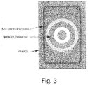
- Fig. 3 shows a schematic diagram for a device for preventing NFC card destruction during wireless charging operations according to an exemplary embodiment of the present invention.
- Fig. 4 shows a schematic diagram for a device for preventing NFC card destruction during wireless charging operations according to an exemplary embodiment of the present invention.
Landscapes
- Engineering & Computer Science (AREA)
- Computer Networks & Wireless Communication (AREA)
- Power Engineering (AREA)
- Charge And Discharge Circuits For Batteries Or The Like (AREA)
Abstract
Description
- The present invention relates to the field of NFC card systems. Particularly, the present invention relates to a device for preventing NFC card destruction by a wireless charging system and a corresponding method.
- With the introduction of the new standards for Qi wireless power transfer for medium power chargers (TX power > 5W), the generated magnetic field is high enough to destroy an NFC card if it is present between the phone and the wireless charger.
- There are two standards, each of which defines the maximum filed intensity limit, at which the NFC card shall withstand:
- 7.5A/m for NFC cards based on ISO 14443
- 5A/m for NFC card based on ISO 15693
- The disadvantages of the prior art are that a wireless charging station needs to integrate NFC function.
- The methods for preventing the destruction of an NFC card is to scan, before starting the wireless charging, for the presence of NFC devices. If a NFC card is detected then the wireless charging of the smartphone battery will not start. This method involves having NFC function in the wireless charging base station.
- There may be a need to improve charging devices to avoid NFC card damages.
- These needs are met by the subject-matter of the independent claims. Further exemplary embodiments are evident from the dependent claims and the following description.
- An aspect of the present invention relates to a device for preventing NFC card destruction during wireless charging operations, the device comprising: a magnetic field detection circuit, which is configured to measure an intensity of a magnetic field generated by a wireless charging system; a NFC-card detection circuit which is configured to detect a presence of a NFC card; and a charging control circuit, which is configured to limit a transmitted power of the wireless charging system during wireless charging operations based on a maximum permitted field, wherein the maximum permitted field is related to the detected presence of the NFC card.
- The proposed idea intend to add to the wireless charging station, a circuit that will measure the magnetic field (H) generated by the charger, and based on card presence and type (ISO 11443 or ISO 15693) detection, and on measured magnetic field to take the decision to limit the transmitted power of the wireless charger.
- The measuring circuit may comprise using a wire loop (single or multiple loops) tuned with a parallel capacitor at 13.56 MHz {which is the operating frequency of the NFC cards).
- That wire loop may be placed above the transmitting coil of the wireless charger, in which the magnetic field generated by the charger. This will induce an AC voltage. The AC voltage will be then rectified with a Schottky Diode - also known as hot carrier diode - or a bridge of diodes and after that the rectified voltage, smoothed with a capacitor will be measured with an ADC input pin of the microcontroller.
- According to the wire loop characteristics (loop size and wire size) a formula to correlate the received DC voltage and the magnetic field can be determined.
- The sensing loop can be made on an FR4 or flex foil PCB placed above the charging coil, as a separate loop used only for field sensing or shared with the existing NFC antenna (the NFC antenna will be used also to measure the induced magnetic field).
- The detection mechanism will be as follows:
- 1) NFC reader integrated in wireless charger scans for existing NFC devices;
- 2) If no devices are detected, then start normal charging;
- 3) If NFC cards are detected, then start charging and monitor in the same time the intensity of the magnetic field induced at 13.56 MHz;
- 4) If the maximum permitted field by the card type detected (Hmax) is exceeded, then the transmitted power of the wireless charger is limited in order to have the magnetic field which passes through the card under Hmax.
- A further, second aspect of the present invention relates to a method for preventing NFC card destruction during wireless charging operations, the method comprising the following steps of: Measuring, by means of a magnetic field detection circuit, an intensity of a magnetic field generated by a wireless charging system; Detecting, by means of a NFC-card detection circuit, a presence of a NFC card; and Limiting, by means of a charging control circuit, a transmitted power of the wireless charging system during wireless charging operations based on a maximum permitted field, wherein the maximum permitted field is related to the detected presence of the NFC card.
- According to an exemplary embodiment of the present invention, the charging control circuit is configured, if no devices are detected by the NFC-card detection circuit, to start normal wireless charging operations, wherein the charging control circuit is configured, if NFC cards are detected, to start limited wireless charging operations and the magnetic field detection circuit is configured to measure, the intensity of the magnetic field induced at the radio frequency band of NFC cards.
- According to an exemplary embodiment of the present invention, the charging control circuit is configured, if the maximum permitted field is exceeded by the intensity of the magnetic field, to reduce the transmitted power of the wireless charger in order to have the magnetic field which passes through the NFC card under the value of the maximum permitted field, Hmax.
- According to an exemplary embodiment of the present invention, the NFC-card detection circuit is configured to detect a type of a detected NFC card.
- According to an exemplary embodiment of the present invention, the magnetic field detection circuit comprises a wire loop tuned with a parallel capacitor at the radio frequency band of NFC cards.
- According to an exemplary embodiment of the present invention, the wire loop is coupled to an FR4 or flex foil PCB and wherein the wire loop is a separate loop used only for field sensing or shared with an existing NFC antenna.
- A computer program performing the method of the present invention may be stored on a computer-readable medium. A computer-readable medium may be a floppy disk, a hard disk, a CD, a DVD, an USB (Universal Serial Bus) storage device, a RAM (Random Access Memory), a ROM (Read Only Memory) or an EPROM (Erasable Programmable Read Only Memory).
- A computer-readable medium may also be a data communication network, for example the Internet, which allows downloading a program code.
- The methods, systems, and devices described herein may be implemented as software in a Digital Signal Processor, DSP, in a micro-controller or in any other side-processor or as a hardware circuit within an application specific integrated circuit, ASIC, CPLD or FPGA.
- The present invention can be implemented in digital electronic circuitry or in computer hardware, firmware, software, or in combinations thereof, for instance in available hardware of conventional medical imaging devices or in new hardware dedicated for processing the methods described herein.
- A more complete appreciation of the invention and the attendant advantages thereof will be clearly understood by reference to the following schematic drawings, which are not to scale, wherein:
- Fig. 1
- shows a schematic flowchart diagram for a method for preventing NFC card destruction during wireless charging operations according to an exemplary embodiment of the present invention;
- Fig. 2
- shows a schematic diagram for a device for preventing NFC card destruction during wireless charging operations according to an exemplary embodiment of the present invention;
- Fig. 3
- shows a schematic diagram for a device for preventing NFC card destruction during wireless charging operations according to an exemplary embodiment of the present invention; and
- Fig. 4
- shows a schematic diagram for a device for preventing NFC card destruction during wireless charging operations according to an exemplary embodiment of the present invention.
- The illustration in the drawings is purely schematic and does not intend to provide scaling relations or size information. In different drawings, similar or identical elements are provided with the same reference numerals.
- Generally, identical parts, units, entities or steps are provided with the same reference symbols in the description.
-
Fig. 1 shows a schematic flowchart diagram for a method for preventing NFC card destruction during wireless charging operations according to an exemplary embodiment of the present invention. - The method for preventing NFC card destruction during wireless charging operations comprises the following steps:
- As a first step of the method, measuring S1, by means of a magnetic
field detection circuit 10, an intensity of a magnetic field H generated by a wireless charging system is performed. - As a second step of the method, detecting S2 a presence of a NFC card is performed by means of a NFC-
card detection circuit 20. - As a third step of the method, limiting S3, by means of a
charging control circuit 30, a transmitted power of the wireless charging system is performed during wireless charging operations based on a maximum permitted field, wherein the maximum permitted field is related to the detected presence of the NFC card. -
Fig. 2 shows a schematic diagram for a device for preventing NFC card destruction during wireless charging operations according to an exemplary embodiment of the present invention. - A
device 100 for preventing NFC card destruction during wireless charging operations comprises a magneticfield detection circuit 10 and a NFC-card detection circuit 20 as well as acharging control circuit 30. - The magnetic
field detection circuit 10 is configured to measure an intensity of a magnetic field H generated by a wireless charging system. - The NFC-
card detection circuit 20 is configured to detect a presence of a NFC card. - The
charging control circuit 30 is configured to limit a transmitted power of the wireless charging system during wireless charging operations based on a maximum permitted field, wherein the maximum permitted field is related to the detected presence of the NFC card. -
Fig. 3 shows a schematic diagram for a device for preventing NFC card destruction during wireless charging operations according to an exemplary embodiment of the present invention. -
Fig. 4 shows a schematic diagram for a device for preventing NFC card destruction during wireless charging operations according to an exemplary embodiment of the present invention. - It has to be noted that embodiments of the present invention are described with reference to different subject-matters. In particular, some embodiments are described with reference to method type claims, whereas other embodiments are described with reference to the device type claims.
- However, a person skilled in the art will gather from the above and the foregoing description that, unless otherwise notified, in addition to any combination of features belonging to one type of the subject-matter also any combination between features relating to different subject-matters is considered to be disclosed with this application.
- However, all features can be combined providing synergetic effects that are more than the simple summation of these features.
- While the invention has been illustrated and described in detail in the drawings and foregoing description, such illustration and description are to be considered illustrative or exemplary and not restrictive; the present invention is not limited to the disclosed embodiments.
- Other variations to the disclosed embodiments can be understood and effected by those skilled in the art and practicing the claimed invention, from a study of the drawings, the disclosure, and the appended claims.
- In the claims, the word "comprising" does not exclude other elements or steps, and the indefinite article "a" or "an" does not exclude a plurality. A single processor or controller or other unit may fulfill the functions of several items recited in the claims.
- The mere fact that certain measures are recited in mutually different dependent claims does not indicate that a combination of these measures cannot be used to advantage. Any reference signs in the claims should not be considered as limiting the scope.
Claims (9)
- A device (100) for preventing NFC card destruction during wireless charging operations, the device (100) comprising:a magnetic field detection circuit (10), which is configured to measure an intensity of a magnetic field (H) generated by a wireless charging system;a NFC-card detection circuit (20), which is configured to detect a presence of a NFC card;a charging control circuit (30), which is configured to limit a transmitted power of the wireless charging system during wireless charging operations based on a maximum permitted field, wherein the maximum permitted field is related to the detected presence of the NFC card.
- The device (100) according to claim 1,
wherein the charging control circuit (30) is configured, if no devices are detected by the NFC-card detection circuit, to start normal wireless charging operations; and
wherein the charging control circuit (30) is configured, if NFC cards are detected, to start limited wireless charging operations and the magnetic field detection circuit (10) is configured to measure, the intensity of the magnetic field induced at the radio frequency band of NFC cards. - The device (100) according to claim 1 or 2,
wherein the charging control circuit (30) is configured, if the maximum permitted field is exceeded by the intensity of the magnetic field, to reduce the transmitted power of the wireless charger in order to have the magnetic field, which passes through the NFC card under the value of the maximum permitted field, Hmax. - The device (100) according to any one of the preceding claims,
wherein the NFC-card detection circuit (20) is configured to detect a type of a detected NFC card. - The device (100) according to any one of the preceding claims,
wherein magnetic field detection circuit (10) comprises a wire loop tuned with a parallel capacitor at the radio frequency band of NFC cards. - The device (100) according to claim 5,
wherein the wire loop is coupled to an FR4 or flex foil PCB and
wherein the wire loop is a separate loop used only for field sensing or shared with an existing NFC antenna. - A method for preventing NFC card destruction during wireless charging operations, the method comprising the following steps of:- Measuring (S1), by means of a magnetic field detection circuit (10), an intensity of a magnetic field (H) generated by a wireless charging system;- Detecting (S2), by means of a NFC-card detection circuit (20), a presence of a NFC card; and- Limiting (S3), by means of a charging control circuit (30), a transmitted power of the wireless charging system during wireless charging operations based on a maximum permitted field, wherein the maximum permitted field is related to the detected presence of the NFC card.
- The method according to claim 7, further comprising the steps of:if no devices are detected by the NFC-card detection circuit, starting normal wireless charging operations;if NFC cards are detected, starting limited wireless charging operations and measuring, the intensity of the magnetic field induced at the radio frequency band of NFC cards.
- The method according to claim 7 or 8, further comprising the steps of:if the maximum permitted field is exceeded by the intensity of the magnetic field, reducing the transmitted power of the wireless charger in order to have the magnetic field which passes through the NFC card under the value of the maximum permitted field.
Priority Applications (2)
| Application Number | Priority Date | Filing Date | Title |
|---|---|---|---|
| EP17465542.3A EP3447875B1 (en) | 2017-08-23 | 2017-08-23 | Device and method for preventing nfc card destruction by a wireless charging system |
| PCT/EP2018/071524 WO2019038089A1 (en) | 2017-08-23 | 2018-08-08 | Device and method for preventing nfc card destruction by a wireless charging system |
Applications Claiming Priority (1)
| Application Number | Priority Date | Filing Date | Title |
|---|---|---|---|
| EP17465542.3A EP3447875B1 (en) | 2017-08-23 | 2017-08-23 | Device and method for preventing nfc card destruction by a wireless charging system |
Publications (2)
| Publication Number | Publication Date |
|---|---|
| EP3447875A1 true EP3447875A1 (en) | 2019-02-27 |
| EP3447875B1 EP3447875B1 (en) | 2022-03-16 |
Family
ID=59829324
Family Applications (1)
| Application Number | Title | Priority Date | Filing Date |
|---|---|---|---|
| EP17465542.3A Active EP3447875B1 (en) | 2017-08-23 | 2017-08-23 | Device and method for preventing nfc card destruction by a wireless charging system |
Country Status (2)
| Country | Link |
|---|---|
| EP (1) | EP3447875B1 (en) |
| WO (1) | WO2019038089A1 (en) |
Cited By (4)
| Publication number | Priority date | Publication date | Assignee | Title |
|---|---|---|---|---|
| US10819394B1 (en) | 2019-10-04 | 2020-10-27 | Nxp B.V. | Detection of NFC proximity IC cards (PICCs) during wireless charging |
| DE102021117142A1 (en) | 2021-07-02 | 2023-01-05 | Infineon Technologies Ag | Wearable device, smart card and system |
| EP4567665A1 (en) | 2023-12-05 | 2025-06-11 | Linxens Holding | Antenna assembly and smart tag or smartcard with such an antenna assembly |
| US12451929B2 (en) | 2022-01-03 | 2025-10-21 | Nxp B.V. | NFC device and method of operating an NFC device |
Families Citing this family (5)
| Publication number | Priority date | Publication date | Assignee | Title |
|---|---|---|---|---|
| EP3869383B1 (en) * | 2020-02-20 | 2023-07-19 | Continental Automotive Technologies GmbH | Method for identifying a passive rfid card |
| CN114013304B (en) * | 2021-12-10 | 2024-05-14 | 重庆金康赛力斯新能源汽车设计院有限公司 | Automobile wireless charging control method and system and automobile |
| CN116325524B (en) * | 2022-06-29 | 2025-02-25 | 华为数字能源技术有限公司 | A power supply device supporting wireless power supply and near field communication |
| US12407195B2 (en) | 2022-09-30 | 2025-09-02 | Nxp B.V. | Method and device for performing a presence check for wireless charging listener devices |
| CN115864685A (en) * | 2022-12-14 | 2023-03-28 | 深圳市恒讯驰技术有限公司 | Method, system and device for vehicle-mounted wireless charging device identification card and safe charging |
Citations (3)
| Publication number | Priority date | Publication date | Assignee | Title |
|---|---|---|---|---|
| US20110221388A1 (en) * | 2010-03-11 | 2011-09-15 | Qualcomm Incorporated | Detection and protection of devices within a wireless power system |
| US20160322853A1 (en) * | 2015-04-28 | 2016-11-03 | Intel Corporation | System and method for safe wireless charging station |
| US20170085297A1 (en) * | 2015-09-23 | 2017-03-23 | Jie Gao | Method, system and apparatus to optimize a4wp wireless charging and nfc co-existence |
-
2017
- 2017-08-23 EP EP17465542.3A patent/EP3447875B1/en active Active
-
2018
- 2018-08-08 WO PCT/EP2018/071524 patent/WO2019038089A1/en not_active Ceased
Patent Citations (3)
| Publication number | Priority date | Publication date | Assignee | Title |
|---|---|---|---|---|
| US20110221388A1 (en) * | 2010-03-11 | 2011-09-15 | Qualcomm Incorporated | Detection and protection of devices within a wireless power system |
| US20160322853A1 (en) * | 2015-04-28 | 2016-11-03 | Intel Corporation | System and method for safe wireless charging station |
| US20170085297A1 (en) * | 2015-09-23 | 2017-03-23 | Jie Gao | Method, system and apparatus to optimize a4wp wireless charging and nfc co-existence |
Cited By (9)
| Publication number | Priority date | Publication date | Assignee | Title |
|---|---|---|---|---|
| US10819394B1 (en) | 2019-10-04 | 2020-10-27 | Nxp B.V. | Detection of NFC proximity IC cards (PICCs) during wireless charging |
| CN112615650A (en) * | 2019-10-04 | 2021-04-06 | 恩智浦有限公司 | Detecting NFC inductive IC card (PICC) during wireless charging |
| CN112615650B (en) * | 2019-10-04 | 2024-02-09 | 恩智浦有限公司 | Detecting NFC inductive IC card (PICC) during wireless charging |
| DE102021117142A1 (en) | 2021-07-02 | 2023-01-05 | Infineon Technologies Ag | Wearable device, smart card and system |
| US20230006477A1 (en) * | 2021-07-02 | 2023-01-05 | Infineon Technologies Ag | Wearable device, smart card and system |
| US12463465B2 (en) * | 2021-07-02 | 2025-11-04 | Infineon Technologies Ag | Wearable device, smart card and system |
| US12451929B2 (en) | 2022-01-03 | 2025-10-21 | Nxp B.V. | NFC device and method of operating an NFC device |
| EP4567665A1 (en) | 2023-12-05 | 2025-06-11 | Linxens Holding | Antenna assembly and smart tag or smartcard with such an antenna assembly |
| WO2025120369A1 (en) | 2023-12-05 | 2025-06-12 | Linxens Holding | Antenna assembly, smart tag or smartcard with such an antenna assembly, and method |
Also Published As
| Publication number | Publication date |
|---|---|
| WO2019038089A1 (en) | 2019-02-28 |
| EP3447875B1 (en) | 2022-03-16 |
Similar Documents
| Publication | Publication Date | Title |
|---|---|---|
| EP3447875B1 (en) | Device and method for preventing nfc card destruction by a wireless charging system | |
| EP3422588B1 (en) | Card detect architecture for near field communications | |
| US20150054453A1 (en) | Apparatus and method for non-compliant object detection | |
| US20190222066A1 (en) | Power feed device | |
| CN107040290B (en) | A wireless charging method, system and computer readable medium | |
| US10085110B2 (en) | Power supply apparatus configured to wirelessly supply power | |
| US20100073138A1 (en) | RFID tag communication system and RFID tag communication apparatus | |
| WO2019050559A1 (en) | Wireless charging system with image-processing-based foreign object detection | |
| EP3493364B1 (en) | Power-supplying system | |
| KR20160043693A (en) | A NFC Card Reader, system including the same, and method there-of | |
| CN104897978A (en) | Electrical activity sensor device for detecting electrical activity and electrical activity monitoring apparatus | |
| US20200274394A1 (en) | Communication device and electronic device having protective function | |
| US9608470B2 (en) | Bank card presence detection to avoid a wireless charger demagnetizing a bank card | |
| US10236721B2 (en) | Power reception apparatus, determination method, and program | |
| US12451929B2 (en) | NFC device and method of operating an NFC device | |
| US11201506B2 (en) | Power transfer system, power receiving apparatus, control method, and storage medium | |
| US10666083B2 (en) | Techniques for wire-free charging | |
| US20180262038A1 (en) | Thermal Management at a Wireless Power System | |
| KR101641112B1 (en) | Method for detecting wideband tapping signal | |
| JP2018163565A (en) | Wireless tag reader and wireless tag reading method | |
| US20180262047A1 (en) | Wireless Power System with Foreign Object Detection and Method Therefor | |
| KR100910200B1 (en) | Method for Detecting Symbols in RFID Systems | |
| CN106160031B (en) | Electronic equipment and information processing method | |
| CN116227513B (en) | Tag communication method, device, equipment and storage medium based on ultrahigh frequency | |
| CN107067063B (en) | Intelligent electronic device |
Legal Events
| Date | Code | Title | Description |
|---|---|---|---|
| PUAI | Public reference made under article 153(3) epc to a published international application that has entered the european phase |
Free format text: ORIGINAL CODE: 0009012 |
|
| STAA | Information on the status of an ep patent application or granted ep patent |
Free format text: STATUS: THE APPLICATION HAS BEEN PUBLISHED |
|
| AK | Designated contracting states |
Kind code of ref document: A1 Designated state(s): AL AT BE BG CH CY CZ DE DK EE ES FI FR GB GR HR HU IE IS IT LI LT LU LV MC MK MT NL NO PL PT RO RS SE SI SK SM TR |
|
| AX | Request for extension of the european patent |
Extension state: BA ME |
|
| STAA | Information on the status of an ep patent application or granted ep patent |
Free format text: STATUS: REQUEST FOR EXAMINATION WAS MADE |
|
| 17P | Request for examination filed |
Effective date: 20190827 |
|
| RBV | Designated contracting states (corrected) |
Designated state(s): AL AT BE BG CH CY CZ DE DK EE ES FI FR GB GR HR HU IE IS IT LI LT LU LV MC MK MT NL NO PL PT RO RS SE SI SK SM TR |
|
| STAA | Information on the status of an ep patent application or granted ep patent |
Free format text: STATUS: EXAMINATION IS IN PROGRESS |
|
| 17Q | First examination report despatched |
Effective date: 20210521 |
|
| GRAP | Despatch of communication of intention to grant a patent |
Free format text: ORIGINAL CODE: EPIDOSNIGR1 |
|
| STAA | Information on the status of an ep patent application or granted ep patent |
Free format text: STATUS: GRANT OF PATENT IS INTENDED |
|
| INTG | Intention to grant announced |
Effective date: 20211129 |
|
| GRAS | Grant fee paid |
Free format text: ORIGINAL CODE: EPIDOSNIGR3 |
|
| GRAA | (expected) grant |
Free format text: ORIGINAL CODE: 0009210 |
|
| STAA | Information on the status of an ep patent application or granted ep patent |
Free format text: STATUS: THE PATENT HAS BEEN GRANTED |
|
| AK | Designated contracting states |
Kind code of ref document: B1 Designated state(s): AL AT BE BG CH CY CZ DE DK EE ES FI FR GB GR HR HU IE IS IT LI LT LU LV MC MK MT NL NO PL PT RO RS SE SI SK SM TR |
|
| REG | Reference to a national code |
Ref country code: GB Ref legal event code: FG4D |
|
| REG | Reference to a national code |
Ref country code: CH Ref legal event code: EP Ref country code: DE Ref legal event code: R096 Ref document number: 602017054614 Country of ref document: DE |
|
| REG | Reference to a national code |
Ref country code: IE Ref legal event code: FG4D |
|
| REG | Reference to a national code |
Ref country code: AT Ref legal event code: REF Ref document number: 1476572 Country of ref document: AT Kind code of ref document: T Effective date: 20220415 |
|
| REG | Reference to a national code |
Ref country code: LT Ref legal event code: MG9D |
|
| REG | Reference to a national code |
Ref country code: DE Ref legal event code: R081 Ref document number: 602017054614 Country of ref document: DE Owner name: CONTINENTAL AUTOMOTIVE TECHNOLOGIES GMBH, DE Free format text: FORMER OWNER: CONTINENTAL AUTOMOTIVE GMBH, 30165 HANNOVER, DE Ref country code: DE Ref legal event code: R081 Ref document number: 602017054614 Country of ref document: DE Owner name: AUMOVIO GERMANY GMBH, DE Free format text: FORMER OWNER: CONTINENTAL AUTOMOTIVE GMBH, 30165 HANNOVER, DE |
|
| REG | Reference to a national code |
Ref country code: NL Ref legal event code: MP Effective date: 20220316 |
|
| PG25 | Lapsed in a contracting state [announced via postgrant information from national office to epo] |
Ref country code: SE Free format text: LAPSE BECAUSE OF FAILURE TO SUBMIT A TRANSLATION OF THE DESCRIPTION OR TO PAY THE FEE WITHIN THE PRESCRIBED TIME-LIMIT Effective date: 20220316 Ref country code: RS Free format text: LAPSE BECAUSE OF FAILURE TO SUBMIT A TRANSLATION OF THE DESCRIPTION OR TO PAY THE FEE WITHIN THE PRESCRIBED TIME-LIMIT Effective date: 20220316 Ref country code: NO Free format text: LAPSE BECAUSE OF FAILURE TO SUBMIT A TRANSLATION OF THE DESCRIPTION OR TO PAY THE FEE WITHIN THE PRESCRIBED TIME-LIMIT Effective date: 20220616 Ref country code: LT Free format text: LAPSE BECAUSE OF FAILURE TO SUBMIT A TRANSLATION OF THE DESCRIPTION OR TO PAY THE FEE WITHIN THE PRESCRIBED TIME-LIMIT Effective date: 20220316 Ref country code: HR Free format text: LAPSE BECAUSE OF FAILURE TO SUBMIT A TRANSLATION OF THE DESCRIPTION OR TO PAY THE FEE WITHIN THE PRESCRIBED TIME-LIMIT Effective date: 20220316 Ref country code: BG Free format text: LAPSE BECAUSE OF FAILURE TO SUBMIT A TRANSLATION OF THE DESCRIPTION OR TO PAY THE FEE WITHIN THE PRESCRIBED TIME-LIMIT Effective date: 20220616 |
|
| REG | Reference to a national code |
Ref country code: AT Ref legal event code: MK05 Ref document number: 1476572 Country of ref document: AT Kind code of ref document: T Effective date: 20220316 |
|
| PG25 | Lapsed in a contracting state [announced via postgrant information from national office to epo] |
Ref country code: LV Free format text: LAPSE BECAUSE OF FAILURE TO SUBMIT A TRANSLATION OF THE DESCRIPTION OR TO PAY THE FEE WITHIN THE PRESCRIBED TIME-LIMIT Effective date: 20220316 Ref country code: GR Free format text: LAPSE BECAUSE OF FAILURE TO SUBMIT A TRANSLATION OF THE DESCRIPTION OR TO PAY THE FEE WITHIN THE PRESCRIBED TIME-LIMIT Effective date: 20220617 Ref country code: FI Free format text: LAPSE BECAUSE OF FAILURE TO SUBMIT A TRANSLATION OF THE DESCRIPTION OR TO PAY THE FEE WITHIN THE PRESCRIBED TIME-LIMIT Effective date: 20220316 |
|
| PG25 | Lapsed in a contracting state [announced via postgrant information from national office to epo] |
Ref country code: NL Free format text: LAPSE BECAUSE OF FAILURE TO SUBMIT A TRANSLATION OF THE DESCRIPTION OR TO PAY THE FEE WITHIN THE PRESCRIBED TIME-LIMIT Effective date: 20220316 |
|
| PG25 | Lapsed in a contracting state [announced via postgrant information from national office to epo] |
Ref country code: SM Free format text: LAPSE BECAUSE OF FAILURE TO SUBMIT A TRANSLATION OF THE DESCRIPTION OR TO PAY THE FEE WITHIN THE PRESCRIBED TIME-LIMIT Effective date: 20220316 Ref country code: SK Free format text: LAPSE BECAUSE OF FAILURE TO SUBMIT A TRANSLATION OF THE DESCRIPTION OR TO PAY THE FEE WITHIN THE PRESCRIBED TIME-LIMIT Effective date: 20220316 Ref country code: RO Free format text: LAPSE BECAUSE OF FAILURE TO SUBMIT A TRANSLATION OF THE DESCRIPTION OR TO PAY THE FEE WITHIN THE PRESCRIBED TIME-LIMIT Effective date: 20220316 Ref country code: PT Free format text: LAPSE BECAUSE OF FAILURE TO SUBMIT A TRANSLATION OF THE DESCRIPTION OR TO PAY THE FEE WITHIN THE PRESCRIBED TIME-LIMIT Effective date: 20220718 Ref country code: ES Free format text: LAPSE BECAUSE OF FAILURE TO SUBMIT A TRANSLATION OF THE DESCRIPTION OR TO PAY THE FEE WITHIN THE PRESCRIBED TIME-LIMIT Effective date: 20220316 Ref country code: EE Free format text: LAPSE BECAUSE OF FAILURE TO SUBMIT A TRANSLATION OF THE DESCRIPTION OR TO PAY THE FEE WITHIN THE PRESCRIBED TIME-LIMIT Effective date: 20220316 Ref country code: CZ Free format text: LAPSE BECAUSE OF FAILURE TO SUBMIT A TRANSLATION OF THE DESCRIPTION OR TO PAY THE FEE WITHIN THE PRESCRIBED TIME-LIMIT Effective date: 20220316 Ref country code: AT Free format text: LAPSE BECAUSE OF FAILURE TO SUBMIT A TRANSLATION OF THE DESCRIPTION OR TO PAY THE FEE WITHIN THE PRESCRIBED TIME-LIMIT Effective date: 20220316 |
|
| PG25 | Lapsed in a contracting state [announced via postgrant information from national office to epo] |
Ref country code: PL Free format text: LAPSE BECAUSE OF FAILURE TO SUBMIT A TRANSLATION OF THE DESCRIPTION OR TO PAY THE FEE WITHIN THE PRESCRIBED TIME-LIMIT Effective date: 20220316 Ref country code: IS Free format text: LAPSE BECAUSE OF FAILURE TO SUBMIT A TRANSLATION OF THE DESCRIPTION OR TO PAY THE FEE WITHIN THE PRESCRIBED TIME-LIMIT Effective date: 20220716 Ref country code: AL Free format text: LAPSE BECAUSE OF FAILURE TO SUBMIT A TRANSLATION OF THE DESCRIPTION OR TO PAY THE FEE WITHIN THE PRESCRIBED TIME-LIMIT Effective date: 20220316 |
|
| REG | Reference to a national code |
Ref country code: DE Ref legal event code: R097 Ref document number: 602017054614 Country of ref document: DE |
|
| PLBE | No opposition filed within time limit |
Free format text: ORIGINAL CODE: 0009261 |
|
| STAA | Information on the status of an ep patent application or granted ep patent |
Free format text: STATUS: NO OPPOSITION FILED WITHIN TIME LIMIT |
|
| PG25 | Lapsed in a contracting state [announced via postgrant information from national office to epo] |
Ref country code: DK Free format text: LAPSE BECAUSE OF FAILURE TO SUBMIT A TRANSLATION OF THE DESCRIPTION OR TO PAY THE FEE WITHIN THE PRESCRIBED TIME-LIMIT Effective date: 20220316 |
|
| 26N | No opposition filed |
Effective date: 20221219 |
|
| PG25 | Lapsed in a contracting state [announced via postgrant information from national office to epo] |
Ref country code: SI Free format text: LAPSE BECAUSE OF FAILURE TO SUBMIT A TRANSLATION OF THE DESCRIPTION OR TO PAY THE FEE WITHIN THE PRESCRIBED TIME-LIMIT Effective date: 20220316 |
|
| REG | Reference to a national code |
Ref country code: GB Ref legal event code: 732E Free format text: REGISTERED BETWEEN 20230223 AND 20230301 |
|
| PG25 | Lapsed in a contracting state [announced via postgrant information from national office to epo] |
Ref country code: MC Free format text: LAPSE BECAUSE OF FAILURE TO SUBMIT A TRANSLATION OF THE DESCRIPTION OR TO PAY THE FEE WITHIN THE PRESCRIBED TIME-LIMIT Effective date: 20220316 |
|
| REG | Reference to a national code |
Ref country code: CH Ref legal event code: PL |
|
| PG25 | Lapsed in a contracting state [announced via postgrant information from national office to epo] |
Ref country code: LU Free format text: LAPSE BECAUSE OF NON-PAYMENT OF DUE FEES Effective date: 20220823 Ref country code: LI Free format text: LAPSE BECAUSE OF NON-PAYMENT OF DUE FEES Effective date: 20220831 Ref country code: CH Free format text: LAPSE BECAUSE OF NON-PAYMENT OF DUE FEES Effective date: 20220831 |
|
| REG | Reference to a national code |
Ref country code: BE Ref legal event code: MM Effective date: 20220831 |
|
| P01 | Opt-out of the competence of the unified patent court (upc) registered |
Effective date: 20230522 |
|
| PG25 | Lapsed in a contracting state [announced via postgrant information from national office to epo] |
Ref country code: IT Free format text: LAPSE BECAUSE OF FAILURE TO SUBMIT A TRANSLATION OF THE DESCRIPTION OR TO PAY THE FEE WITHIN THE PRESCRIBED TIME-LIMIT Effective date: 20220316 Ref country code: IE Free format text: LAPSE BECAUSE OF NON-PAYMENT OF DUE FEES Effective date: 20220823 |
|
| PG25 | Lapsed in a contracting state [announced via postgrant information from national office to epo] |
Ref country code: BE Free format text: LAPSE BECAUSE OF NON-PAYMENT OF DUE FEES Effective date: 20220831 |
|
| REG | Reference to a national code |
Ref country code: DE Ref legal event code: R081 Ref document number: 602017054614 Country of ref document: DE Owner name: CONTINENTAL AUTOMOTIVE TECHNOLOGIES GMBH, DE Free format text: FORMER OWNER: CONTINENTAL AUTOMOTIVE TECHNOLOGIES GMBH, 30165 HANNOVER, DE Ref country code: DE Ref legal event code: R081 Ref document number: 602017054614 Country of ref document: DE Owner name: AUMOVIO GERMANY GMBH, DE Free format text: FORMER OWNER: CONTINENTAL AUTOMOTIVE TECHNOLOGIES GMBH, 30165 HANNOVER, DE |
|
| PG25 | Lapsed in a contracting state [announced via postgrant information from national office to epo] |
Ref country code: HU Free format text: LAPSE BECAUSE OF FAILURE TO SUBMIT A TRANSLATION OF THE DESCRIPTION OR TO PAY THE FEE WITHIN THE PRESCRIBED TIME-LIMIT; INVALID AB INITIO Effective date: 20170823 |
|
| PG25 | Lapsed in a contracting state [announced via postgrant information from national office to epo] |
Ref country code: CY Free format text: LAPSE BECAUSE OF FAILURE TO SUBMIT A TRANSLATION OF THE DESCRIPTION OR TO PAY THE FEE WITHIN THE PRESCRIBED TIME-LIMIT Effective date: 20220316 |
|
| PG25 | Lapsed in a contracting state [announced via postgrant information from national office to epo] |
Ref country code: MK Free format text: LAPSE BECAUSE OF FAILURE TO SUBMIT A TRANSLATION OF THE DESCRIPTION OR TO PAY THE FEE WITHIN THE PRESCRIBED TIME-LIMIT Effective date: 20220316 |
|
| PG25 | Lapsed in a contracting state [announced via postgrant information from national office to epo] |
Ref country code: TR Free format text: LAPSE BECAUSE OF FAILURE TO SUBMIT A TRANSLATION OF THE DESCRIPTION OR TO PAY THE FEE WITHIN THE PRESCRIBED TIME-LIMIT Effective date: 20220316 |
|
| PG25 | Lapsed in a contracting state [announced via postgrant information from national office to epo] |
Ref country code: MT Free format text: LAPSE BECAUSE OF FAILURE TO SUBMIT A TRANSLATION OF THE DESCRIPTION OR TO PAY THE FEE WITHIN THE PRESCRIBED TIME-LIMIT Effective date: 20220316 |
|
| PGFP | Annual fee paid to national office [announced via postgrant information from national office to epo] |
Ref country code: DE Payment date: 20250831 Year of fee payment: 9 |
|
| PGFP | Annual fee paid to national office [announced via postgrant information from national office to epo] |
Ref country code: GB Payment date: 20250821 Year of fee payment: 9 |
|
| PGFP | Annual fee paid to national office [announced via postgrant information from national office to epo] |
Ref country code: FR Payment date: 20250828 Year of fee payment: 9 |
|
| REG | Reference to a national code |
Ref country code: DE Ref legal event code: R079 Ref document number: 602017054614 Country of ref document: DE Free format text: PREVIOUS MAIN CLASS: H02J0005000000 Ipc: H02J0004250000 |
|
| REG | Reference to a national code |
Ref country code: DE Ref legal event code: R081 Ref document number: 602017054614 Country of ref document: DE Owner name: AUMOVIO GERMANY GMBH, DE Free format text: FORMER OWNER: CONTINENTAL AUTOMOTIVE TECHNOLOGIES GMBH, 30175 HANNOVER, DE |