EP3447853A1 - Shielded connector - Google Patents
Shielded connector Download PDFInfo
- Publication number
- EP3447853A1 EP3447853A1 EP18190077.0A EP18190077A EP3447853A1 EP 3447853 A1 EP3447853 A1 EP 3447853A1 EP 18190077 A EP18190077 A EP 18190077A EP 3447853 A1 EP3447853 A1 EP 3447853A1
- Authority
- EP
- European Patent Office
- Prior art keywords
- main body
- cover tab
- protrusion
- shell main
- shell
- Prior art date
- Legal status (The legal status is an assumption and is not a legal conclusion. Google has not performed a legal analysis and makes no representation as to the accuracy of the status listed.)
- Withdrawn
Links
- 230000000149 penetrating effect Effects 0.000 claims abstract description 6
- 238000003780 insertion Methods 0.000 claims description 6
- 230000037431 insertion Effects 0.000 claims description 6
- 239000012212 insulator Substances 0.000 abstract description 12
- 239000004020 conductor Substances 0.000 description 9
- 239000000463 material Substances 0.000 description 7
- 230000013011 mating Effects 0.000 description 5
- 238000001746 injection moulding Methods 0.000 description 3
- 239000011347 resin Substances 0.000 description 3
- 229920005989 resin Polymers 0.000 description 3
- 230000000630 rising effect Effects 0.000 description 3
- 238000009413 insulation Methods 0.000 description 2
- 230000000717 retained effect Effects 0.000 description 2
- 230000004308 accommodation Effects 0.000 description 1
- 238000005452 bending Methods 0.000 description 1
- 230000015556 catabolic process Effects 0.000 description 1
- 238000011109 contamination Methods 0.000 description 1
- 238000002788 crimping Methods 0.000 description 1
- 238000006731 degradation reaction Methods 0.000 description 1
- 230000000994 depressogenic effect Effects 0.000 description 1
- 230000000694 effects Effects 0.000 description 1
- 238000000605 extraction Methods 0.000 description 1
- 239000002184 metal Substances 0.000 description 1
- 239000007769 metal material Substances 0.000 description 1
- 239000000243 solution Substances 0.000 description 1
Images




Classifications
-
- H—ELECTRICITY
- H01—ELECTRIC ELEMENTS
- H01R—ELECTRICALLY-CONDUCTIVE CONNECTIONS; STRUCTURAL ASSOCIATIONS OF A PLURALITY OF MUTUALLY-INSULATED ELECTRICAL CONNECTING ELEMENTS; COUPLING DEVICES; CURRENT COLLECTORS
- H01R13/00—Details of coupling devices of the kinds covered by groups H01R12/70 or H01R24/00 - H01R33/00
- H01R13/648—Protective earth or shield arrangements on coupling devices, e.g. anti-static shielding
- H01R13/658—High frequency shielding arrangements, e.g. against EMI [Electro-Magnetic Interference] or EMP [Electro-Magnetic Pulse]
- H01R13/6581—Shield structure
-
- H—ELECTRICITY
- H01—ELECTRIC ELEMENTS
- H01R—ELECTRICALLY-CONDUCTIVE CONNECTIONS; STRUCTURAL ASSOCIATIONS OF A PLURALITY OF MUTUALLY-INSULATED ELECTRICAL CONNECTING ELEMENTS; COUPLING DEVICES; CURRENT COLLECTORS
- H01R13/00—Details of coupling devices of the kinds covered by groups H01R12/70 or H01R24/00 - H01R33/00
- H01R13/648—Protective earth or shield arrangements on coupling devices, e.g. anti-static shielding
- H01R13/658—High frequency shielding arrangements, e.g. against EMI [Electro-Magnetic Interference] or EMP [Electro-Magnetic Pulse]
- H01R13/6591—Specific features or arrangements of connection of shield to conductive members
- H01R13/6592—Specific features or arrangements of connection of shield to conductive members the conductive member being a shielded cable
- H01R13/6593—Specific features or arrangements of connection of shield to conductive members the conductive member being a shielded cable the shield being composed of different pieces
-
- H—ELECTRICITY
- H01—ELECTRIC ELEMENTS
- H01R—ELECTRICALLY-CONDUCTIVE CONNECTIONS; STRUCTURAL ASSOCIATIONS OF A PLURALITY OF MUTUALLY-INSULATED ELECTRICAL CONNECTING ELEMENTS; COUPLING DEVICES; CURRENT COLLECTORS
- H01R12/00—Structural associations of a plurality of mutually-insulated electrical connecting elements, specially adapted for printed circuits, e.g. printed circuit boards [PCB], flat or ribbon cables, or like generally planar structures, e.g. terminal strips, terminal blocks; Coupling devices specially adapted for printed circuits, flat or ribbon cables, or like generally planar structures; Terminals specially adapted for contact with, or insertion into, printed circuits, flat or ribbon cables, or like generally planar structures
- H01R12/70—Coupling devices
- H01R12/7005—Guiding, mounting, polarizing or locking means; Extractors
-
- H—ELECTRICITY
- H01—ELECTRIC ELEMENTS
- H01R—ELECTRICALLY-CONDUCTIVE CONNECTIONS; STRUCTURAL ASSOCIATIONS OF A PLURALITY OF MUTUALLY-INSULATED ELECTRICAL CONNECTING ELEMENTS; COUPLING DEVICES; CURRENT COLLECTORS
- H01R13/00—Details of coupling devices of the kinds covered by groups H01R12/70 or H01R24/00 - H01R33/00
- H01R13/46—Bases; Cases
- H01R13/502—Bases; Cases composed of different pieces
- H01R13/506—Bases; Cases composed of different pieces assembled by snap action of the parts
-
- H—ELECTRICITY
- H01—ELECTRIC ELEMENTS
- H01R—ELECTRICALLY-CONDUCTIVE CONNECTIONS; STRUCTURAL ASSOCIATIONS OF A PLURALITY OF MUTUALLY-INSULATED ELECTRICAL CONNECTING ELEMENTS; COUPLING DEVICES; CURRENT COLLECTORS
- H01R13/00—Details of coupling devices of the kinds covered by groups H01R12/70 or H01R24/00 - H01R33/00
- H01R13/46—Bases; Cases
- H01R13/516—Means for holding or embracing insulating body, e.g. casing, hoods
- H01R13/518—Means for holding or embracing insulating body, e.g. casing, hoods for holding or embracing several coupling parts, e.g. frames
-
- H—ELECTRICITY
- H01—ELECTRIC ELEMENTS
- H01R—ELECTRICALLY-CONDUCTIVE CONNECTIONS; STRUCTURAL ASSOCIATIONS OF A PLURALITY OF MUTUALLY-INSULATED ELECTRICAL CONNECTING ELEMENTS; COUPLING DEVICES; CURRENT COLLECTORS
- H01R13/00—Details of coupling devices of the kinds covered by groups H01R12/70 or H01R24/00 - H01R33/00
- H01R13/62—Means for facilitating engagement or disengagement of coupling parts or for holding them in engagement
- H01R13/639—Additional means for holding or locking coupling parts together, after engagement, e.g. separate keylock, retainer strap
-
- H—ELECTRICITY
- H01—ELECTRIC ELEMENTS
- H01R—ELECTRICALLY-CONDUCTIVE CONNECTIONS; STRUCTURAL ASSOCIATIONS OF A PLURALITY OF MUTUALLY-INSULATED ELECTRICAL CONNECTING ELEMENTS; COUPLING DEVICES; CURRENT COLLECTORS
- H01R13/00—Details of coupling devices of the kinds covered by groups H01R12/70 or H01R24/00 - H01R33/00
- H01R13/648—Protective earth or shield arrangements on coupling devices, e.g. anti-static shielding
- H01R13/658—High frequency shielding arrangements, e.g. against EMI [Electro-Magnetic Interference] or EMP [Electro-Magnetic Pulse]
- H01R13/6581—Shield structure
- H01R13/6582—Shield structure with resilient means for engaging mating connector
-
- H—ELECTRICITY
- H01—ELECTRIC ELEMENTS
- H01R—ELECTRICALLY-CONDUCTIVE CONNECTIONS; STRUCTURAL ASSOCIATIONS OF A PLURALITY OF MUTUALLY-INSULATED ELECTRICAL CONNECTING ELEMENTS; COUPLING DEVICES; CURRENT COLLECTORS
- H01R24/00—Two-part coupling devices, or either of their cooperating parts, characterised by their overall structure
- H01R24/60—Contacts spaced along planar side wall transverse to longitudinal axis of engagement
- H01R24/62—Sliding engagements with one side only, e.g. modular jack coupling devices
Definitions
- the present invention relates to an electrical connector having an electromagnetic shielding function.
- an electrical connector provided with an electromagnetic shield shell (outer conductor) surrounding an inner conductor is used as disclosed for example in patent JP2011-60613A .
- JP2011-60613A describes a shielded connector provided with an inner conductor connected to an electrical wire, an inner insulator accommodating the inner conductor, an outer conductor surrounding the inner insulator, and an outer insulator provided outside the outer conductor.
- the shield shell By providing a window penetrating the shield shell along the wall thickness, and catching in the window an insulator lance or the like, the shield shell can be retained to the insulators. However, a degradation in electromagnetic shielding performance due to the window acting as a gap in the electromagnetic shield should be avoided.
- the shielded connector of JP2011-60613A1 has difficulty in retaining the outer conductor to the inner insulator and/or the outer insulator since the outer conductor is not provided with the window.
- an object of the present invention is to provide a shielded connector capable of achieving sufficient electromagnetic shielding performance while retaining a shield shell to an insulator.
- a shielded connector of the present invention is provided with a housing accommodating a contact and a shield shell surrounding the housing from outside, the housing has a catch protrusion inserted from inside into an opening penetrating the shield shell, the shield shell has a shell main body formed with the opening, and a cover tab supported by the shell main body and covering the opening while being set back from the catch protrusion toward outside.
- the shell main body be formed in a tubular shape and have a seam along an axial-line direction, and the cover tab be supported in a cantilever-like manner at either one of one end portion and another end portion of the shell main body joined together at the seam, and extend in a direction perpendicular to the axial-line direction in the outside over the opening.
- the shielded connector of the present invention be further provided with an outer housing surrounding the shield shell from the outside, and the cover tab be held between the outer housing and the shell main body, causing a portion of the cover tab to come into contact with the shell main body to establish electrical continuity.
- the outer housing has a catch portion caught by the cover tab.
- the cover tab is supported in a cantilever-like manner by the shell main body, and a free end portion of the cover tab has a contact portion protruding toward the shell main body.
- the cover tab is supported in a cantilever-like manner by the shell main body, the outer housing is formed with a first protrusion protruding toward the inside toward a free end portion of the cover tab, and the free end portion is pressed between the first protrusion and the shell main body.
- the outer housing is formed with a guide groove capable of guiding, in a direction of insertion for the shield shell to be inserted into the outer housing, the cover tab extending in a direction perpendicular to the direction of insertion, and the first protrusion and a catch portion caught by the cover tab nearer a supported end of the cover tab than the first protrusion are formed inside the guide groove.
- the cover tab has at a free end portion a second protrusion protruding toward the outside from a portion covering the opening, and the second protrusion comes into contact with the outer housing, causing the free end portion to be pressed between the outer housing and the shell main body.
- the cover tab that the shield shell is provided with covers the opening while being set back from the catch protrusion of the housing toward the outside, regardless of the opening being formed in the shield shell, electromagnetic noise entry and/or emission through the opening can be avoided. Therefore, the electromagnetic shielding performance of the connector can be improved while a structure for retaining the shield shell to an insulator housing by the catch protrusion being inserted into the opening is maintained.
- a connector 1 shown in Figure 1 and Figure 2 is a shielded connector having an electromagnetic shielding function.
- the connector 1 of the present embodiment is suitable for use in an on-board device for vehicle.
- the electromagnetic shielding function of the connector 1 can suppress electromagnetic noise emission to the outside from the device and/or influence of electromagnetic noise received from another device.
- the connector 1 is to be mated with a mating connector (not shown) connected to a board or the like of the device along an axial line A ( Figure 1(c) ) set in the connector 1.
- axial line A Figure 1(c)
- the connector 1 ( Figure 1 and Figure 2 ) is provided with an inner housing 10 that is an insulator, a shield shell 20 that is a conductor, and an outer housing 30 that is an insulator.
- the inner housing 10 is surrounded by the shield shell 20 around the axis.
- the shield shell 20 is surrounded by the outer housing 30 around the axis.
- the inner housing 10 retains two contacts (not shown) having conductivity.
- the inner housing 10 is formed from a resin material having an insulation property by injection molding in a substantially rectangular-parallelepiped-like shape having four walls around the axis.
- the connector 1 may be provided with a single or more than two contacts.
- Cavities 12, 12 accommodating the contacts therein are formed in the inner housing 10 ( Figure 2 ).
- the mating connector (not shown) is to be mated to a front end portion 10A of the inner housing 10.
- a front end side of the connector 1 is denoted by F
- a rear end side of the connector 1 is denoted by R.
- the cavities 12, 12 penetrate the inner housing 10 in a direction of plugging/extraction of the connector 1 into/from the mating connector. Electrical wires (not shown) connected via crimping portions of the contacts are each led out to the rear sides of the cavities 12, 12.
- a central (axial line A) side where the contacts are located is referred to as "inside”
- an outer-peripheral side distant from the axial line A in a direction perpendicular to the axial line A is referred to as "outside”.
- a catch beam 14 caught by a portion of the shield shell 20 is provided on one sidewall 13 of the inner housing 10.
- the catch beam 14 is supported in the vicinity of the front end portion 10A of the inner housing 10, and extends to the rear side.
- a catch protrusion 14A protruding toward the outside is formed at a free end portion of the catch beam 14.
- a front end 14B ( Figure 4(b) ) of the catch protrusion 14A is inclined relative to an axial-line direction D1.
- a rear end 14C ( Figure 4(b) ) of the catch protrusion 14A rises substantially perpendicularly to the axial-line direction D1.
- the shield shell 20 ( Figure 2 , Figure 3 ) surrounds from the outside the inner housing 10 retaining the contacts.
- the shield shell 20 is grounded to the electrical wires (not shown) connected to the contacts retained by the inner housing 10, and to a casing of the device provided with the mating connector.
- the shield shell 20 imparts an electromagnetic shielding function to the connector 1.
- the shield shell 20 integrally has a shell main body 21 and a cover tab 22 supported by the shell main body 21, and is made from a material having conductivity and elasticity.
- the shield shell 20 of the present embodiment is so formed as to be rectangular in cross section by stamping out a sheet material formed from a metal material along the wall thickness and bending it into a rectangular-tube-like shape.
- An opening 210 penetrating the shield shell 20 in a direction from the inside/outside toward the outside/inside is formed in the shell main body 21.
- a dimension from a sidewall 23 of the shell main body 21 where the opening 210 is located to an opposite sidewall 24 is set such that the catch beam 14 is pressed toward the inside and deflected by the sidewall 23 of the shell main body 21 when the inner housing 10 is inserted into the shield shell 20 in a direction of the axial line A (axial-line direction D1) from the rear side of the shield shell 20.
- the rectangular-tube-like shell main body 21, as shown in Figure 3(a) has a seam 21S along the axial-line direction D1.
- the seam 21S is located at a widthwise center of the sidewall 23 of the shell main body 21.
- the shell main body 21 is formed in a tubular shape such that end faces of one end portion 211 and another end portion 212 of the sheet material abut on each other at the seam 21S.
- a tongue 212A protruding from the other end portion 212 fits in a notch 211A of the one end portion 211, thereby preventing the one end portion 211 and the other end portion 212 from being separated.
- the opening 210 is formed in a substantially rectangular shape as a whole by combining a notch formed in the one end portion 211 by lancing the cover tab 22 and a notch formed in the other end portion 212.
- the cover tab 22 electromagnetically closes the opening 210 so that a gap of the electromagnetic shield may not occur at the position of the opening 210 penetrating the shield shell 20.
- the cover tab 22 is not located inside the opening 210, but offset toward the outside from the opening 210.
- the cover tab 22 is supported by the shell main body 21 in a cantilever-like manner by lancing a portion of the sheet material forming the shield shell 20. Since being lanced toward the outside from the shell main body 21, the cover tab 22 covers the opening 210 from the outside while being set back from the catch protrusion 14A inserted into the opening 210 of the shell main body 21.
- the cover tab 22 integrally extends into the one end portion 211 of the shell main body 21, and extends in a direction perpendicular to the direction of the axial line (axial-line direction D1) of the shell main body 21 (widthwise) in the outside over the opening 210. A distal end portion of the cover tab 22 reaches the sidewall 23 beyond the opening 210.
- the cover tab 22 is formed in a rectangular shape as viewed from above.
- the cover tab 22 has a supported end portion 22A rising toward the outside from the shell main body 21 and a free end portion 22B extending substantially along the sidewall 23 from the supported end portion 22A.
- a contact portion 22C ( Figure 3(b) , Figure 4(a) ) protruding toward the sidewall 23 of the shell main body 21 is formed in the vicinity of a distal end of the free end portion 22B.
- the cover tab 22 covers the opening 210 from the outside with the catch protrusion 14A being caught in the opening 210.
- the contact portion 22C is raised out by pressing from an outer side of the cover tab 22, thus being so formed as to protrude toward the inside.
- the outer housing 30 (also referred to as enclosure), as shown in Figure 1(c) , surrounds the shield shell 20 from the outside.
- the shield shell 20 is inserted from the rear side of the outer housing 30 to a front end of an accommodation space formed inside the outer housing 30, the cover tab 22 held between the outer housing 30 and the shell main body 21 is pressed by a portion of the outer housing 30 and thus deflected toward the inside.
- the contact portion 22C of the free end portion 22B of the cover tab 22 comes into contact with the shell main body 21, as shown in Figure 4(a) , to establish electrical continuity.
- the shell main body 21 may be provided with a contact portion protruding toward an inner side of the free end portion 22B of the cover tab 22.
- the outer housing 30 is so formed from a resin material having an insulation property by injection molding as to have the appearance of a rectangular parallelepiped having sidewalls each corresponding to four sidewalls of the shell main body 21. It should be noted that the outer housing 30 may be formed from a resin or metal having conductivity.
- a catch beam 34 caught by the cover tab 22 of the shield shell 20 is provided on an inner side (back side) of one sidewall 33 of the outer housing 30. The catch beam 34 is caught by the cover tab 22 nearer the supported end portion 22A than a portion of the cover tab 22 pressed toward the shell main body 21 by a portion of the outer housing 30.
- the catch beam 34 extends from the rear side toward the front side.
- a catch protrusion 34A protruding toward the inside is formed at a free-end side of the catch beam 34.
- the catch protrusion 34A is caught by the cover tab 22 from behind.
- a rear end 34B ( Figure 4(b) ) of the catch protrusion 34A is inclined relative to the axial-line direction D1.
- a front end 34C ( Figure 4(b) ) of the catch protrusion 34A rises substantially perpendicularly to the axial-line direction D1.
- Figures 5(a) and 5(b) show the catch beam 34 and a pressing protrusion 35 (first protrusion) for pressing the free end portion 22B of the cover tab 22.
- the catch beam 34 and the pressing protrusion 35 are formed inside a guide groove 36 extending in the direction of the axial line of the shield shell 20 (axial-line direction D1) on the bottom side of the sidewall 33 of the outer housing 30.
- the guide groove 36 is depressed toward the outside from the bottom side of the sidewall 33, and receives the cover tab 22 rising from the shell main body 21 from the rear side.
- the cover tab 22 is shifted inside the guide groove 36 from a position indicated by a chain line to a position indicated by a chain double-dashed line in Figure 5(a) .
- the catch beam 34 and the pressing protrusion 35 are formed between inner walls 361, 362 extending along the axial-line direction D1 in the guide groove 36.
- the inner walls 361, 362 extend into a rear end 30B ( Figure 1(c) ) of the outer housing 30.
- the catch beam 34 is defined inside the inner walls 361, 362 of the guide groove 36 by grooves 341, 341 recessed from the bottom portion 36A of the guide groove 36.
- the catch protrusion 34A of the catch beam 34 protrudes toward the inside beyond an inner face of the sidewall 33 around the guide groove 36.
- a groove 37 ( Figure 1(c) , Figure 2 ) extending into a front end 30A of the outer housing 30 beyond a front wall 363 of the guide groove 36 is formed.
- the pressing protrusion 35 protrudes toward the inside from the bottom portion 36A of the guide groove 36 in a position corresponding to the free end portion 22B of the cover tab 22.
- the pressing protrusion 35 is located beside the catch protrusion 34A.
- One side face of the pressing protrusion 35 extends flush with a wall face of the groove 341.
- the pressing protrusion 35 has a flat apex portion 35A substantially parallel to the sidewall 23 of the shell main body 21.
- the apex portion 35A is so formed in a position corresponding to the contact portion 22C of the cover tab 22 as to have a size corresponding to the contact portion 22C.
- a side face 35D of the pressing protrusion 35 expands from the apex portion 35A to the bottom portion 36A of the guide groove 36.
- a rear end 35B of the pressing protrusion 35 is inclined relative to the axial-line direction D1, and a front end 35C ( Figure 5(b) ) of the pressing protrusion 35 rises substantially perpendicularly to the axial-line direction D1.
- the apex portion 35A of the pressing protrusion 35 remains inside the guide groove 36, as shown in Figure 4(a) .
- the free end portion 22B of the cover tab 22 is pressed inwardly toward the shell main body 21 by the apex portion 35A.
- the cover tab 22 When the shield shell 20 is inserted into the outer housing 30, the cover tab 22 is guided in the axial-line direction D1 by the inner walls 361, 362 of the guide groove 36 from the rear end 30B ( Figure 1(c) ) of the outer housing 30. As the shield shell 20 is being inserted to the front end of the accommodating space inside the outer housing 30, the cover tab 22 gets over the catch protrusion 34A from the rear side toward the front side, while deflecting the catch beam 34 toward the outside, to be disposed in the position indicated by the chain double-dashed line in Figure 5(a) . Hereat, as shown in Figure 4(b) , the front end 34C of the catch protrusion 34A is caught by the rear end 22D of the cover tab 22.
- the catch beam 34 retains the shield shell 20 to the outer housing 30, and simultaneously the free end portion 22B of the cover tab 22 is pressed between the pressing protrusion 35 ( Figure 4(a) ) and the shell main body 21, which causes the contact portion 22C to come into contact with the shell main body 21 to establish electrical continuity. Since the pressing protrusion 35 presses the cover tab 22 to the shell main body 21, a sufficient contact pressure is secured between the cover tab 22 and the shell main body 21.
- the cover tab 22 the shield shell 20 is provided with covers the opening 210 while being set back from the catch protrusion 14A of the inner housing 10 toward the outside. Therefore, regardless of the opening 210 formed in the shield shell 20, electromagnetic noise entry and/or emission through the opening 210 can be avoided. Therefore, the electromagnetic shielding performance of the connector 1 can be improved while a structure for retaining the shield shell 20 to the inner housing 10 by inserting the catch protrusion 14A into the opening 210 is maintained. Then, electromagnetic noise contamination of the devices provided with the connector 1 and the mating connector or the like and/or of signals transmitted through the electrical wires is avoided, and thus the reliability of communication can be improved.
- the cover tab 22 Since not only covering the opening 210 but also catching the catch protrusion 34A of the outer housing 30, the cover tab 22 also functions to retain the shield shell 20 to the outer housing 30. Moreover, since the free end portion 22B of the cover tab 22 pressed between the outer housing 30 and the shell main body 21 comes into contact with the shell main body 21 to establish electrical continuity, electromagnetic noise entry into the cover tab 22 and/or electromagnetic noise emission from the cover tab 22 can be avoided.
- the cover tab 22 is set back from the catch protrusion 14A toward the outside, and rises from the shell main body 21 by a dimension slightly larger than the wall thickness to the extent necessary to catch the catch protrusion 34A. Then, the free end portion 22B is pressed by the pressing protrusion 35 of the outer housing 30, and thus brought into contact with the shell main body 21. Accordingly, the cover tab 22 extends along the shell main body 21 as a whole, and both end sides of the cover tab 22 are electrically connected to the shell main body 21, so that the cover tab 22 is substantially integrally coupled with the shell main body 21 electromagnetically.
- a region discontinuous from the shell main body 21 is limited to a distal-end side from the contact portion 22C of the cover tab 22, so that the cover tab 22 itself can avoid becoming a source of emission and/or a source of reception of electromagnetic noise as much as possible.
- a connector 2 like the connector 1 of the above embodiment, is provided with the inner housing 10, the shield shell 20, and the outer housing 30.
- a cover tab 42 of the shield shell 20 is provided which is supported by the shell main body 21 in a cantilever-like manner, as shown in Figure 7(a) , and has at a free end portion a pressed protrusion 45 (second protrusion) protruding toward the outside from a portion covering the opening 210 from the outside.
- the pressing protrusion 35 ( Figure 4(a) ) is not formed on the outer housing 30.
- a cover portion 42A which is the portion of the cover tab 42 ( Figure 7(a) ) covering the opening 210 from the outside, is configured in a similar manner to the cover tab 22 ( Figure 3 ) of the above embodiment.
- the cover tab 42 is composed of the cover portion 42A and the pressed protrusion 45.
- the pressed protrusion 45 is stamped from the sheet material of the shield shell 20 integrally with the cover potion 42A, and bent in an out-of-plane direction relative to the cover portion 42A.
- the pressed protrusion 45 extends in a direction perpendicular to the cover portion 42A, while gradually rising toward the outside, from a distal end portion (free end portion) of the cover portion 42A.
- the cover portion 42A extends in the direction perpendicular to the axial-line direction D1, whereas the pressed protrusion 45 extends in the axial-line direction D1.
- the cover tab 42 When the shield shell 20 is inserted into the outer housing 30 from the rear side, the cover tab 42 is guided in the axial-line direction D1 by the guide groove 36. As shown in Figure 6(b) and Figure 7(b) , the pressed protrusion 45 comes into contact with the bottom portion 36A of the guide groove 36, which causes the free end portion of the cover tab 42 to be pressed between the outer housing 30 and the shell main body 21, so that the contact portion 22C ( Figure 6(b) ) of the cover tab 42 comes into contact with the shell main body 21 with a sufficient contact pressure. That is, the pressed protrusion 45 functions in a similar manner to the pressing protrusion 35 of the above embodiment.
- any configuration described in the above embodiment may be selectively adopted or removed, or such a configuration may be replaced with another configuration, if necessary.
- the inner housing 10, the shield shell 20, and the outer housing 30 are configured to be rectangular in cross section, but these may be configured to be circular in cross section.
- the cover tab 22 be curved from the supported end portion to the contact portion, and extend along an outer wall of the shell main body 21, because this enables avoidance of electromagnetic noise emission from and/or entry into the cover tab 22.
- the cover tab 22 extends in the direction of the width perpendicular to the axial-line direction D1, but the cover tab in the present invention may extend in the axial-line direction D1.
- the connector of the present invention is applicable not only to on-board devices for vehicle but also to various devices.
- the connector of the present invention is provided with a housing retaining a contact and a shield shell surrounding the housing from the outside, and the shield shell is provided with a cover tab for covering an opening formed in a shell main body of the shield shell while being set back from a catch protrusion of the housing inserted into the opening from the inside, its component is allowed to be selectively adopted or removed, and/or changed, if necessary.
- the connector of the present invention may not be provided with the outer housing 30 surrounding the shield shell 20 from the outside.
Landscapes
- Details Of Connecting Devices For Male And Female Coupling (AREA)
Abstract
Description
- The present invention relates to an electrical connector having an electromagnetic shielding function.
- In order to suppress electromagnetic noise emission from a device to the outside and/or the influence of electromagnetic noise received from another device, an electrical connector provided with an electromagnetic shield shell (outer conductor) surrounding an inner conductor is used as disclosed for example in patent
JP2011-60613A -
JP2011-60613A - By providing a window penetrating the shield shell along the wall thickness, and catching in the window an insulator lance or the like, the shield shell can be retained to the insulators. However, a degradation in electromagnetic shielding performance due to the window acting as a gap in the electromagnetic shield should be avoided. The shielded connector of
JP2011-60613A1 - In view of these circumstance, an object of the present invention is to provide a shielded connector capable of achieving sufficient electromagnetic shielding performance while retaining a shield shell to an insulator.
- A shielded connector of the present invention is provided with a housing accommodating a contact and a shield shell surrounding the housing from outside, the housing has a catch protrusion inserted from inside into an opening penetrating the shield shell, the shield shell has a shell main body formed with the opening, and a cover tab supported by the shell main body and covering the opening while being set back from the catch protrusion toward outside.
- In the shielded connector of the present invention, it is preferred that the shell main body be formed in a tubular shape and have a seam along an axial-line direction, and the cover tab be supported in a cantilever-like manner at either one of one end portion and another end portion of the shell main body joined together at the seam, and extend in a direction perpendicular to the axial-line direction in the outside over the opening.
- It is preferred that the shielded connector of the present invention be further provided with an outer housing surrounding the shield shell from the outside, and the cover tab be held between the outer housing and the shell main body, causing a portion of the cover tab to come into contact with the shell main body to establish electrical continuity.
- In the shielded connector of the present invention, it is preferred that the outer housing has a catch portion caught by the cover tab.
- In the shielded connector of the present invention, it is preferred that the cover tab is supported in a cantilever-like manner by the shell main body, and a free end portion of the cover tab has a contact portion protruding toward the shell main body.
- In the shielded connector of the present invention, it is preferred that the cover tab is supported in a cantilever-like manner by the shell main body, the outer housing is formed with a first protrusion protruding toward the inside toward a free end portion of the cover tab, and the free end portion is pressed between the first protrusion and the shell main body.
- In the shielded connector of the present invention, it is preferred that the outer housing is formed with a guide groove capable of guiding, in a direction of insertion for the shield shell to be inserted into the outer housing, the cover tab extending in a direction perpendicular to the direction of insertion, and the first protrusion and a catch portion caught by the cover tab nearer a supported end of the cover tab than the first protrusion are formed inside the guide groove.
- In the shielded connector of the present invention, it is preferred that the cover tab has at a free end portion a second protrusion protruding toward the outside from a portion covering the opening, and the second protrusion comes into contact with the outer housing, causing the free end portion to be pressed between the outer housing and the shell main body.
- According to the present invention, since the cover tab that the shield shell is provided with covers the opening while being set back from the catch protrusion of the housing toward the outside, regardless of the opening being formed in the shield shell, electromagnetic noise entry and/or emission through the opening can be avoided. Therefore, the electromagnetic shielding performance of the connector can be improved while a structure for retaining the shield shell to an insulator housing by the catch protrusion being inserted into the opening is maintained.
-
-
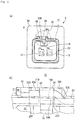
Figures 1(a) to 1(c) are views showing a shielded connector according to an embodiment of the present invention.Figure 1(a) is a front view of the shielded connector, andFigure 1(b) is a rear view of the shielded connector.Figure 1(c) is a cross sectional view taken along a line Ic-Ic ofFigure 1(a) . -
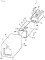
Figure 2 is an exploded isometric view of the shielded connector shown inFigure 1 . -
Figure 3(a) is an isometric view showing an inner housing and a shield shell.Figure 3(b) is an isometric view showing a cover tab of the shield shell. -
Figure 4(a) is an enlarged view of a portion IV ofFigure 1(b) .Figure 4(b) is a partially enlarged view ofFigure 1(c) . -
Figure 5(a) is an isometric view showing the inside of an outer housing.Figure 5(b) is a bottom view showing the inside of the outer housing. -
Figures 6(a) and 6(b) are views showing a shielded connector according to a variation of the present invention.Figure 6(a) is a rear view of the shielded connector according to the variation.Figure 6(b) is an enlarged view of a portion VIb ofFigure 6(a) . -
Figure 7(a) is an isometric view of a shield shell of the shielded connector shown inFigure 6 , andFigure 7(b) is a longitudinal sectional view of the shielded connector at a position corresponding to a line VIIb-VIIb ofFigure 7(a) . - Hereinafter, with reference to the accompanying drawings, an embodiment of the present invention will be described. A
connector 1 shown inFigure 1 andFigure 2 is a shielded connector having an electromagnetic shielding function. Theconnector 1 of the present embodiment is suitable for use in an on-board device for vehicle. The electromagnetic shielding function of theconnector 1 can suppress electromagnetic noise emission to the outside from the device and/or influence of electromagnetic noise received from another device. Theconnector 1 is to be mated with a mating connector (not shown) connected to a board or the like of the device along an axial line A (Figure 1(c) ) set in theconnector 1. Hereinafter, "around the axis" refers to around the axial line A. - The connector 1 (
Figure 1 andFigure 2 ) is provided with aninner housing 10 that is an insulator, ashield shell 20 that is a conductor, and anouter housing 30 that is an insulator. Theinner housing 10 is surrounded by theshield shell 20 around the axis. Theshield shell 20 is surrounded by theouter housing 30 around the axis. Theinner housing 10 retains two contacts (not shown) having conductivity. Theinner housing 10 is formed from a resin material having an insulation property by injection molding in a substantially rectangular-parallelepiped-like shape having four walls around the axis. Theconnector 1 may be provided with a single or more than two contacts. -
Cavities Figure 2 ). The mating connector (not shown) is to be mated to afront end portion 10A of theinner housing 10. In each of the drawings, a front end side of theconnector 1 is denoted by F, and a rear end side of theconnector 1 is denoted by R.
Thecavities inner housing 10 in a direction of plugging/extraction of theconnector 1 into/from the mating connector. Electrical wires (not shown) connected via crimping portions of the contacts are each led out to the rear sides of thecavities - In the
connector 1, a central (axial line A) side where the contacts are located is referred to as "inside", and an outer-peripheral side distant from the axial line A in a direction perpendicular to the axial line A is referred to as "outside". - A
catch beam 14 caught by a portion of theshield shell 20 is provided on onesidewall 13 of theinner housing 10. Thecatch beam 14 is supported in the vicinity of thefront end portion 10A of theinner housing 10, and extends to the rear side. Acatch protrusion 14A protruding toward the outside is formed at a free end portion of thecatch beam 14. In order that thecatch beam 14 can be deflected by a small force when theinner housing 10 is inserted into theshield shell 20 from the rear side, afront end 14B (Figure 4(b) ) of thecatch protrusion 14A is inclined relative to an axial-line direction D1. On the other hand, arear end 14C (Figure 4(b) ) of thecatch protrusion 14A rises substantially perpendicularly to the axial-line direction D1. - Next, the shield shell 20 (
Figure 2 ,Figure 3 ) surrounds from the outside theinner housing 10 retaining the contacts. Theshield shell 20 is grounded to the electrical wires (not shown) connected to the contacts retained by theinner housing 10, and to a casing of the device provided with the mating connector. Theshield shell 20 imparts an electromagnetic shielding function to theconnector 1. - The
shield shell 20 integrally has a shellmain body 21 and acover tab 22 supported by the shellmain body 21, and is made from a material having conductivity and elasticity. Theshield shell 20 of the present embodiment is so formed as to be rectangular in cross section by stamping out a sheet material formed from a metal material along the wall thickness and bending it into a rectangular-tube-like shape. - An
opening 210 penetrating theshield shell 20 in a direction from the inside/outside toward the outside/inside is formed in the shellmain body 21. A dimension from asidewall 23 of the shellmain body 21 where theopening 210 is located to anopposite sidewall 24 is set such that thecatch beam 14 is pressed toward the inside and deflected by thesidewall 23 of the shellmain body 21 when theinner housing 10 is inserted into theshield shell 20 in a direction of the axial line A (axial-line direction D1) from the rear side of theshield shell 20. - As shown in
Figure 1(c) , once theinner housing 10 is inserted to thefront end 20A of theshield shell 20, thecatch protrusion 14A is inserted into the opening 210 from the inside. Hereat, as shown inFigure 4(b) , therear end 14C of thecatch protrusion 14A is caught by a rear end edge of theopening 210 opposite therear end 14C. Then, thecatch beam 14 retains theshield shell 20 to theinner housing 10. - The rectangular-tube-like shell
main body 21, as shown inFigure 3(a) , has aseam 21S along the axial-line direction D1. Theseam 21S is located at a widthwise center of thesidewall 23 of the shellmain body 21. The shellmain body 21 is formed in a tubular shape such that end faces of oneend portion 211 and anotherend portion 212 of the sheet material abut on each other at theseam 21S. Atongue 212A protruding from theother end portion 212 fits in anotch 211A of the oneend portion 211, thereby preventing the oneend portion 211 and theother end portion 212 from being separated. - The
opening 210 is formed in a substantially rectangular shape as a whole by combining a notch formed in the oneend portion 211 by lancing thecover tab 22 and a notch formed in theother end portion 212. - The
cover tab 22 electromagnetically closes theopening 210 so that a gap of the electromagnetic shield may not occur at the position of theopening 210 penetrating theshield shell 20. Thecover tab 22 is not located inside theopening 210, but offset toward the outside from theopening 210. - The
cover tab 22 is supported by the shellmain body 21 in a cantilever-like manner by lancing a portion of the sheet material forming theshield shell 20. Since being lanced toward the outside from the shellmain body 21, thecover tab 22 covers the opening 210 from the outside while being set back from thecatch protrusion 14A inserted into theopening 210 of the shellmain body 21. Thecover tab 22 integrally extends into the oneend portion 211 of the shellmain body 21, and extends in a direction perpendicular to the direction of the axial line (axial-line direction D1) of the shell main body 21 (widthwise) in the outside over theopening 210. A distal end portion of thecover tab 22 reaches thesidewall 23 beyond theopening 210. Thecover tab 22 is formed in a rectangular shape as viewed from above. - The
cover tab 22 has a supportedend portion 22A rising toward the outside from the shellmain body 21 and afree end portion 22B extending substantially along thesidewall 23 from the supportedend portion 22A. Acontact portion 22C (Figure 3(b) ,Figure 4(a) ) protruding toward thesidewall 23 of the shellmain body 21 is formed in the vicinity of a distal end of thefree end portion 22B. Thecover tab 22 covers the opening 210 from the outside with thecatch protrusion 14A being caught in theopening 210. Thecontact portion 22C is raised out by pressing from an outer side of thecover tab 22, thus being so formed as to protrude toward the inside. Although being separated from the surface of the shellmain body 21 in an unloaded state shown inFigure 3(b) , once theouter housing 30 is assembled onto theshield shell 20, thecontact portion 22C of thefree end portion 22B comes into contact with the shellmain body 21, as shown inFigure 4(a) , to establish electrical continuity. - Next, the outer housing 30 (also referred to as enclosure), as shown in
Figure 1(c) , surrounds theshield shell 20 from the outside. When theshield shell 20 is inserted from the rear side of theouter housing 30 to a front end of an accommodation space formed inside theouter housing 30, thecover tab 22 held between theouter housing 30 and the shellmain body 21 is pressed by a portion of theouter housing 30 and thus deflected toward the inside. Then, thecontact portion 22C of thefree end portion 22B of thecover tab 22 comes into contact with the shellmain body 21, as shown inFigure 4(a) , to establish electrical continuity. - It should be noted that, instead of the
cover tab 22 being provided with thecontact portion 22C, the shellmain body 21 may be provided with a contact portion protruding toward an inner side of thefree end portion 22B of thecover tab 22. - The
outer housing 30 is so formed from a resin material having an insulation property by injection molding as to have the appearance of a rectangular parallelepiped having sidewalls each corresponding to four sidewalls of the shellmain body 21. It should be noted that theouter housing 30 may be formed from a resin or metal having conductivity. Acatch beam 34 caught by thecover tab 22 of theshield shell 20 is provided on an inner side (back side) of onesidewall 33 of theouter housing 30. Thecatch beam 34 is caught by thecover tab 22 nearer the supportedend portion 22A than a portion of thecover tab 22 pressed toward the shellmain body 21 by a portion of theouter housing 30. - The
catch beam 34 extends from the rear side toward the front side. Acatch protrusion 34A protruding toward the inside is formed at a free-end side of thecatch beam 34. As shown inFigure 1(c) , thecatch protrusion 34A is caught by thecover tab 22 from behind. In order that thecatch beam 34 can be deflected by a small force when theshield shell 20 is inserted into theouter housing 30 from the rear side, arear end 34B (Figure 4(b) ) of thecatch protrusion 34A is inclined relative to the axial-line direction D1. On the other hand, afront end 34C (Figure 4(b) ) of thecatch protrusion 34A rises substantially perpendicularly to the axial-line direction D1. -
Figures 5(a) and 5(b) show thecatch beam 34 and a pressing protrusion 35 (first protrusion) for pressing thefree end portion 22B of thecover tab 22. Thecatch beam 34 and thepressing protrusion 35 are formed inside aguide groove 36 extending in the direction of the axial line of the shield shell 20 (axial-line direction D1) on the bottom side of thesidewall 33 of theouter housing 30. Theguide groove 36 is depressed toward the outside from the bottom side of thesidewall 33, and receives thecover tab 22 rising from the shellmain body 21 from the rear side. As theshield shell 20 is being inserted into theouter housing 30 in the axial-line direction D1 (direction of insertion), thecover tab 22 is shifted inside theguide groove 36 from a position indicated by a chain line to a position indicated by a chain double-dashed line inFigure 5(a) . - The
catch beam 34 and thepressing protrusion 35 are formed betweeninner walls guide groove 36. Theinner walls rear end 30B (Figure 1(c) ) of theouter housing 30. - The
catch beam 34 is defined inside theinner walls guide groove 36 bygrooves bottom portion 36A of theguide groove 36. Thecatch protrusion 34A of thecatch beam 34 protrudes toward the inside beyond an inner face of thesidewall 33 around theguide groove 36. In order that thecatch protrusion 34A can be extracted from a mold in the axial-line direction D1 at the time of injection molding, a groove 37 (Figure 1(c) ,Figure 2 ) extending into afront end 30A of theouter housing 30 beyond afront wall 363 of theguide groove 36 is formed. - The
pressing protrusion 35 protrudes toward the inside from thebottom portion 36A of theguide groove 36 in a position corresponding to thefree end portion 22B of thecover tab 22. Thepressing protrusion 35 is located beside thecatch protrusion 34A. One side face of thepressing protrusion 35 extends flush with a wall face of thegroove 341. Thepressing protrusion 35 has aflat apex portion 35A substantially parallel to thesidewall 23 of the shellmain body 21. Theapex portion 35A is so formed in a position corresponding to thecontact portion 22C of thecover tab 22 as to have a size corresponding to thecontact portion 22C. In order that a sufficient rigidity to press thecontact portion 22C can be imparted to thepressing protrusion 35, aside face 35D of thepressing protrusion 35 expands from theapex portion 35A to thebottom portion 36A of theguide groove 36. Like thecatch protrusion 34A, arear end 35B of thepressing protrusion 35 is inclined relative to the axial-line direction D1, and afront end 35C (Figure 5(b) ) of thepressing protrusion 35 rises substantially perpendicularly to the axial-line direction D1. - The
apex portion 35A of thepressing protrusion 35 remains inside theguide groove 36, as shown inFigure 4(a) . As a result of a dimensional relation between theshield shell 20 and theouter housing 30 when theshield shell 20 and theouter housing 30 are assembled together, inside theguide groove 36, thefree end portion 22B of thecover tab 22 is pressed inwardly toward the shellmain body 21 by theapex portion 35A. - When the
shield shell 20 is inserted into theouter housing 30, thecover tab 22 is guided in the axial-line direction D1 by theinner walls guide groove 36 from therear end 30B (Figure 1(c) ) of theouter housing 30. As theshield shell 20 is being inserted to the front end of the accommodating space inside theouter housing 30, thecover tab 22 gets over thecatch protrusion 34A from the rear side toward the front side, while deflecting thecatch beam 34 toward the outside, to be disposed in the position indicated by the chain double-dashed line inFigure 5(a) . Hereat, as shown inFigure 4(b) , thefront end 34C of thecatch protrusion 34A is caught by therear end 22D of thecover tab 22. Therefore, thecatch beam 34 retains theshield shell 20 to theouter housing 30, and simultaneously thefree end portion 22B of thecover tab 22 is pressed between the pressing protrusion 35 (Figure 4(a) ) and the shellmain body 21, which causes thecontact portion 22C to come into contact with the shellmain body 21 to establish electrical continuity. Since thepressing protrusion 35 presses thecover tab 22 to the shellmain body 21, a sufficient contact pressure is secured between thecover tab 22 and the shellmain body 21. - The
catch protrusion 14A of theinner housing 10, as shown inFigure 1(c) andFigure 4(a) , is located inside theopening 210. Therefore, even when theshield shell 20 and theinner housing 10 is assembled together in advance, thecatch protrusion 14A of theinner housing 10 and thecatch protrusion 34A of theouter housing 30 do not interfere with each other. As shown inFigure 4(b) , it is preferred that anapex portion 34D of thecatch protrusion 34A be in contact with the surface of the shellmain body 21 and adistal end portion 34E of thecatch beam 34 be in contact with the surface of thecover tab 22 because this causes thecatch beam 34 to stably retain theshield shell 20 to theouter housing 30. - According to the present embodiment described above, the
cover tab 22 theshield shell 20 is provided with covers theopening 210 while being set back from thecatch protrusion 14A of theinner housing 10 toward the outside. Therefore, regardless of theopening 210 formed in theshield shell 20, electromagnetic noise entry and/or emission through theopening 210 can be avoided. Therefore, the electromagnetic shielding performance of theconnector 1 can be improved while a structure for retaining theshield shell 20 to theinner housing 10 by inserting thecatch protrusion 14A into theopening 210 is maintained. Then, electromagnetic noise contamination of the devices provided with theconnector 1 and the mating connector or the like and/or of signals transmitted through the electrical wires is avoided, and thus the reliability of communication can be improved. - Since not only covering the
opening 210 but also catching thecatch protrusion 34A of theouter housing 30, thecover tab 22 also functions to retain theshield shell 20 to theouter housing 30. Moreover, since thefree end portion 22B of thecover tab 22 pressed between theouter housing 30 and the shellmain body 21 comes into contact with the shellmain body 21 to establish electrical continuity, electromagnetic noise entry into thecover tab 22 and/or electromagnetic noise emission from thecover tab 22 can be avoided. - As shown in
Figure 4(a) , thecover tab 22 is set back from thecatch protrusion 14A toward the outside, and rises from the shellmain body 21 by a dimension slightly larger than the wall thickness to the extent necessary to catch thecatch protrusion 34A. Then, thefree end portion 22B is pressed by the pressingprotrusion 35 of theouter housing 30, and thus brought into contact with the shellmain body 21. Accordingly, thecover tab 22 extends along the shellmain body 21 as a whole, and both end sides of thecover tab 22 are electrically connected to the shellmain body 21, so that thecover tab 22 is substantially integrally coupled with the shellmain body 21 electromagnetically. According to the present embodiment, a region discontinuous from the shellmain body 21 is limited to a distal-end side from thecontact portion 22C of thecover tab 22, so that thecover tab 22 itself can avoid becoming a source of emission and/or a source of reception of electromagnetic noise as much as possible. - With reference to
Figure 6 andFigure 7 , a variation of the present invention will be described. Aconnector 2, like theconnector 1 of the above embodiment, is provided with theinner housing 10, theshield shell 20, and theouter housing 30. Acover tab 42 of theshield shell 20 is provided which is supported by the shellmain body 21 in a cantilever-like manner, as shown inFigure 7(a) , and has at a free end portion a pressed protrusion 45 (second protrusion) protruding toward the outside from a portion covering theopening 210 from the outside. - As shown in
Figure 6(b) , the pressing protrusion 35 (Figure 4(a) ) is not formed on theouter housing 30. A portion adjacent to thecatch beam 34 in thebottom portion 36A of theguide groove 36, namely, a portion where thepressing protrusion 35 might have been formed, is flatly formed. - A
cover portion 42A, which is the portion of the cover tab 42 (Figure 7(a) ) covering theopening 210 from the outside, is configured in a similar manner to the cover tab 22 (Figure 3 ) of the above embodiment. Thecover tab 42 is composed of thecover portion 42A and the pressedprotrusion 45. The pressedprotrusion 45 is stamped from the sheet material of theshield shell 20 integrally with thecover potion 42A, and bent in an out-of-plane direction relative to thecover portion 42A. - The pressed
protrusion 45 extends in a direction perpendicular to thecover portion 42A, while gradually rising toward the outside, from a distal end portion (free end portion) of thecover portion 42A. Thecover portion 42A extends in the direction perpendicular to the axial-line direction D1, whereas the pressedprotrusion 45 extends in the axial-line direction D1. - When the
shield shell 20 is inserted into theouter housing 30 from the rear side, thecover tab 42 is guided in the axial-line direction D1 by theguide groove 36. As shown inFigure 6(b) andFigure 7(b) , the pressedprotrusion 45 comes into contact with thebottom portion 36A of theguide groove 36, which causes the free end portion of thecover tab 42 to be pressed between theouter housing 30 and the shellmain body 21, so that thecontact portion 22C (Figure 6(b) ) of thecover tab 42 comes into contact with the shellmain body 21 with a sufficient contact pressure. That is, the pressedprotrusion 45 functions in a similar manner to thepressing protrusion 35 of the above embodiment. - In addition to the above, without departing from the scope of the present invention, any configuration described in the above embodiment may be selectively adopted or removed, or such a configuration may be replaced with another configuration, if necessary.
- In the above embodiment, the
inner housing 10, theshield shell 20, and theouter housing 30 are configured to be rectangular in cross section, but these may be configured to be circular in cross section. In that case, it is preferred that, following the shape of the shellmain body 21, thecover tab 22 be curved from the supported end portion to the contact portion, and extend along an outer wall of the shellmain body 21, because this enables avoidance of electromagnetic noise emission from and/or entry into thecover tab 22. In addition, in the above embodiment, thecover tab 22 extends in the direction of the width perpendicular to the axial-line direction D1, but the cover tab in the present invention may extend in the axial-line direction D1. - The connector of the present invention is applicable not only to on-board devices for vehicle but also to various devices. As long as the connector of the present invention is provided with a housing retaining a contact and a shield shell surrounding the housing from the outside, and the shield shell is provided with a cover tab for covering an opening formed in a shell main body of the shield shell while being set back from a catch protrusion of the housing inserted into the opening from the inside, its component is allowed to be selectively adopted or removed, and/or changed, if necessary. The connector of the present invention may not be provided with the
outer housing 30 surrounding theshield shell 20 from the outside. -
- 1, 2...connector (shielded connector),
- 10...inner housing (housing),
- 10A...front end portion,
- 12...cavity,
- 13...sidewall,
- 14...catch beam,
- 14A... catch protrusion,
- 14B...front end,
- 14C...rear end,
- 20...shield shell,
- 20A...front end,
- 21...shell main body,
- 21S...seam,
- 22...cover tab,
- 22A... supported end portion,
- 22B...free end portion,
- 22C...contact portion,
- 22D...rear end,
- 23, 24...sidewall,
- 30...outer housing,
- 30A...front end,
- 30B...rear end,
- 33...sidewall,
- 34...catch beam (catch portion),
- 34A...catch protrusion,
- 34B...rear end,
- 34C...front end,
- 34D...apex portion,
- 34E...distal end portion,
- 35...pressing protrusion (first protrusion),
- 35A...apex portion,
- 35B...rear end,
- 35C...front end,
- 35D...side face,
- 36...guide groove,
- 36A...bottom portion,
- 37...groove,
- 42...cover tab,
- 42A...cover portion,
- 45...pressed protrusion (second protrusion),
- 210...opening,
- 211...one end portion,
- 212...another end portion (the other end portion),
- 341...groove,
- 361, 362...inner wall,
- 363...front wall,
- A... axial line,
- D1...axial-line direction (direction of insertion).
Claims (8)
- A shielded connector (1) comprising:a housing (10) accommodating a contact; anda shield shell (20) surrounding the housing (10) from outside, whereinthe housing (10) has a catch protrusion (34A) inserted from inside into an opening (210) penetrating the shield shell (20), andthe shield shell (20) has a shell main body (21) formed with the opening (210), and a cover tab (22) supported by the shell main body (21) and covering the opening (210) and being set back from the catch protrusion (34A) toward outside.
- The shielded connector (1) according to claim 1, wherein
the shell main body (21) is formed in a tubular shape and has a seam (215) along an axial-line direction (D1), and
the cover tab (22) is supported in a cantilever-like manner at either one of one end portion (211) and another end portion (212) of the shell main body (21) joined together at the seam (21S), and extends in a direction perpendicular to the axial-line direction (D1) in the outside over the opening (210). - The shielded connector (1) according to claim 1 or 2, further comprising:an outer housing (30) surrounding the shield shell (20) from the outside, whereinthe cover tab (22) is held between the outer housing (30) and the shell main body (21), causing a portion of the cover tab (22) to come into contact with the shell main body (21) to establish electrical continuity.
- The shielded connector (1) according to claim 3, wherein the outer housing (30) has a catch portion (34) caught by the cover tab (22).
- The shielded connector (1) according to claim 3 or 4, wherein
the cover tab (22) is supported in a cantilever-like manner by the shell main body (21), and
a free end portion (22B) of the cover tab (22) has a contact portion (22C) protruding toward the shell main body (21). - The shielded connector (1) according to any one of claims 3 to 5, wherein
the cover tab (22) is supported in a cantilever-like manner by the shell main body (21),
the outer housing (30) is formed with a first protrusion (35) protruding toward the inside toward a free end portion (22B) of the cover tab (22), and
the free end portion (22B) is pressed between the first protrusion (35) and the shell main body (21). - The shielded connector (1) according to claim 6, wherein
the outer housing (30) is formed with a guide groove (36) capable of guiding, in a direction of insertion (D1) for the shield shell (20) to be inserted into the outer housing (30), the cover tab (22) extending in a direction perpendicular to the direction of insertion (D1), and
the first protrusion (35) and a catch portion (34) caught by the cover tab (22) nearer a supported end (22A) of the cover tab (22) than the first protrusion (35) are formed inside the guide groove (36). - The shielded connector (2) according to any one of claims 3 to 5, wherein
the cover tab (42) has at a free end portion a second protrusion (45) protruding toward the outside from a portion covering the opening (210), and
the second protrusion (45) comes into contact with the outer housing (30), causing the free end portion to be pressed between the outer housing (30) and the shell main body (21).
Applications Claiming Priority (1)
| Application Number | Priority Date | Filing Date | Title |
|---|---|---|---|
| JP2017160147A JP2019040690A (en) | 2017-08-23 | 2017-08-23 | Shield connector |
Publications (1)
| Publication Number | Publication Date |
|---|---|
| EP3447853A1 true EP3447853A1 (en) | 2019-02-27 |
Family
ID=63350469
Family Applications (1)
| Application Number | Title | Priority Date | Filing Date |
|---|---|---|---|
| EP18190077.0A Withdrawn EP3447853A1 (en) | 2017-08-23 | 2018-08-21 | Shielded connector |
Country Status (4)
| Country | Link |
|---|---|
| US (1) | US10608383B2 (en) |
| EP (1) | EP3447853A1 (en) |
| JP (1) | JP2019040690A (en) |
| CN (1) | CN109428237A (en) |
Families Citing this family (9)
| Publication number | Priority date | Publication date | Assignee | Title |
|---|---|---|---|---|
| JP2020043024A (en) * | 2018-09-13 | 2020-03-19 | 矢崎総業株式会社 | Board connector |
| CN110113926B (en) * | 2019-05-30 | 2021-01-08 | 维沃移动通信有限公司 | Shielding structure and terminal |
| EP3787130A1 (en) * | 2019-08-27 | 2021-03-03 | TE Connectivity Germany GmbH | Connector shielding with a guiding protrusion |
| JP7491193B2 (en) * | 2020-11-20 | 2024-05-28 | 住友電装株式会社 | Connector Unit |
| JP7522680B2 (en) * | 2021-02-17 | 2024-07-25 | 日本航空電子工業株式会社 | Shielded Connectors |
| CN114243323B (en) * | 2021-12-23 | 2024-05-07 | 友嘉众邦电缆有限公司 | Mining control shielding type cable connector and manufacturing method |
| JP7461394B2 (en) * | 2022-01-31 | 2024-04-03 | 住友電装株式会社 | shield connector |
| CN218123810U (en) * | 2022-08-31 | 2022-12-23 | 泰科电子(上海)有限公司 | Connectors and Connector Assemblies |
| DE102023109903A1 (en) * | 2023-04-19 | 2024-10-24 | Te Connectivity Solutions Gmbh | housing arrangement, connector and connection device |
Citations (7)
| Publication number | Priority date | Publication date | Assignee | Title |
|---|---|---|---|---|
| US7229317B2 (en) * | 2004-01-30 | 2007-06-12 | Finisar Corporation | Shielding tabs for reduction of electromagnetic interference |
| EP2034564A2 (en) * | 2007-09-06 | 2009-03-11 | HONDA TSUSHIN KOGYO Co., Ltd. | Mold case attached with retainer |
| JP2010182647A (en) * | 2009-02-09 | 2010-08-19 | Sumitomo Wiring Syst Ltd | Shield connector and shield shell |
| JP2011060613A (en) | 2009-09-10 | 2011-03-24 | Japan Aviation Electronics Industry Ltd | Connector assembly |
| US8840435B2 (en) * | 2010-07-30 | 2014-09-23 | Tyco Electronics Amp Italia Srl | Electrical connector with an outer housing, an inner housing and an indicator sleeve |
| WO2016125668A1 (en) * | 2015-02-05 | 2016-08-11 | 株式会社オートネットワーク技術研究所 | Shield connector |
| CN205944619U (en) * | 2016-06-07 | 2017-02-08 | 富士康(昆山)电脑接插件有限公司 | Electric connector |
-
2017
- 2017-08-23 JP JP2017160147A patent/JP2019040690A/en active Pending
-
2018
- 2018-08-21 EP EP18190077.0A patent/EP3447853A1/en not_active Withdrawn
- 2018-08-22 CN CN201810959551.9A patent/CN109428237A/en active Pending
- 2018-08-22 US US16/108,679 patent/US10608383B2/en active Active
Patent Citations (7)
| Publication number | Priority date | Publication date | Assignee | Title |
|---|---|---|---|---|
| US7229317B2 (en) * | 2004-01-30 | 2007-06-12 | Finisar Corporation | Shielding tabs for reduction of electromagnetic interference |
| EP2034564A2 (en) * | 2007-09-06 | 2009-03-11 | HONDA TSUSHIN KOGYO Co., Ltd. | Mold case attached with retainer |
| JP2010182647A (en) * | 2009-02-09 | 2010-08-19 | Sumitomo Wiring Syst Ltd | Shield connector and shield shell |
| JP2011060613A (en) | 2009-09-10 | 2011-03-24 | Japan Aviation Electronics Industry Ltd | Connector assembly |
| US8840435B2 (en) * | 2010-07-30 | 2014-09-23 | Tyco Electronics Amp Italia Srl | Electrical connector with an outer housing, an inner housing and an indicator sleeve |
| WO2016125668A1 (en) * | 2015-02-05 | 2016-08-11 | 株式会社オートネットワーク技術研究所 | Shield connector |
| CN205944619U (en) * | 2016-06-07 | 2017-02-08 | 富士康(昆山)电脑接插件有限公司 | Electric connector |
Also Published As
| Publication number | Publication date |
|---|---|
| JP2019040690A (en) | 2019-03-14 |
| US10608383B2 (en) | 2020-03-31 |
| US20190067882A1 (en) | 2019-02-28 |
| CN109428237A (en) | 2019-03-05 |
Similar Documents
| Publication | Publication Date | Title |
|---|---|---|
| EP3447853A1 (en) | Shielded connector | |
| US10644416B2 (en) | Connector | |
| US8915750B2 (en) | Plug connector with mis-insert features and corresponding receptacle connector therewith | |
| JP5771094B2 (en) | Shield connector | |
| US10594056B2 (en) | Terminal fitting | |
| US9425564B2 (en) | Connector | |
| EP0981180B1 (en) | Shielded connector | |
| JP6708025B2 (en) | Shielded connector | |
| JP2016072067A (en) | connector | |
| US7134900B2 (en) | Electrical connector assembly with multi-function latching member | |
| CN108352661B (en) | Connector with a locking member | |
| US6929512B2 (en) | Cable end connector assembly with a shield device | |
| US10530094B2 (en) | Electrical connector | |
| CN108808289B (en) | Electrical connector and electrical connector device | |
| US9627815B2 (en) | Receptacle connector for cable | |
| US7229298B2 (en) | Electrical connector having an improved grounding path | |
| US9077136B2 (en) | Combination electrical connector and assembly of the same | |
| CN110870143B (en) | Terminal parts | |
| JP5048580B2 (en) | Shield connector | |
| CN108808395B (en) | Electric connector and electric connector device | |
| JP4184370B2 (en) | Electrical connector | |
| US20230261423A1 (en) | Shield connector | |
| JP5128359B2 (en) | Shield connector | |
| JP2019145463A (en) | connector | |
| JP2003068406A (en) | Connector with shield case |
Legal Events
| Date | Code | Title | Description |
|---|---|---|---|
| PUAI | Public reference made under article 153(3) epc to a published international application that has entered the european phase |
Free format text: ORIGINAL CODE: 0009012 |
|
| STAA | Information on the status of an ep patent application or granted ep patent |
Free format text: STATUS: THE APPLICATION HAS BEEN PUBLISHED |
|
| AK | Designated contracting states |
Kind code of ref document: A1 Designated state(s): AL AT BE BG CH CY CZ DE DK EE ES FI FR GB GR HR HU IE IS IT LI LT LU LV MC MK MT NL NO PL PT RO RS SE SI SK SM TR |
|
| AX | Request for extension of the european patent |
Extension state: BA ME |
|
| STAA | Information on the status of an ep patent application or granted ep patent |
Free format text: STATUS: REQUEST FOR EXAMINATION WAS MADE |
|
| 17P | Request for examination filed |
Effective date: 20190722 |
|
| RBV | Designated contracting states (corrected) |
Designated state(s): AL AT BE BG CH CY CZ DE DK EE ES FI FR GB GR HR HU IE IS IT LI LT LU LV MC MK MT NL NO PL PT RO RS SE SI SK SM TR |
|
| STAA | Information on the status of an ep patent application or granted ep patent |
Free format text: STATUS: EXAMINATION IS IN PROGRESS |
|
| 17Q | First examination report despatched |
Effective date: 20191209 |
|
| GRAP | Despatch of communication of intention to grant a patent |
Free format text: ORIGINAL CODE: EPIDOSNIGR1 |
|
| STAA | Information on the status of an ep patent application or granted ep patent |
Free format text: STATUS: GRANT OF PATENT IS INTENDED |
|
| INTG | Intention to grant announced |
Effective date: 20201008 |
|
| STAA | Information on the status of an ep patent application or granted ep patent |
Free format text: STATUS: THE APPLICATION IS DEEMED TO BE WITHDRAWN |
|
| 18D | Application deemed to be withdrawn |
Effective date: 20210219 |