EP3447852B1 - Differential connector - Google Patents
Differential connector Download PDFInfo
- Publication number
- EP3447852B1 EP3447852B1 EP17833206.0A EP17833206A EP3447852B1 EP 3447852 B1 EP3447852 B1 EP 3447852B1 EP 17833206 A EP17833206 A EP 17833206A EP 3447852 B1 EP3447852 B1 EP 3447852B1
- Authority
- EP
- European Patent Office
- Prior art keywords
- shield
- differential
- module
- plug
- adjacent
- Prior art date
- Legal status (The legal status is an assumption and is not a legal conclusion. Google has not performed a legal analysis and makes no representation as to the accuracy of the status listed.)
- Active
Links
Images


Classifications
-
- H—ELECTRICITY
- H01—ELECTRIC ELEMENTS
- H01R—ELECTRICALLY-CONDUCTIVE CONNECTIONS; STRUCTURAL ASSOCIATIONS OF A PLURALITY OF MUTUALLY-INSULATED ELECTRICAL CONNECTING ELEMENTS; COUPLING DEVICES; CURRENT COLLECTORS
- H01R13/00—Details of coupling devices of the kinds covered by groups H01R12/70 or H01R24/00 - H01R33/00
- H01R13/648—Protective earth or shield arrangements on coupling devices, e.g. anti-static shielding
- H01R13/658—High frequency shielding arrangements, e.g. against EMI [Electro-Magnetic Interference] or EMP [Electro-Magnetic Pulse]
- H01R13/6598—Shield material
- H01R13/6599—Dielectric material made conductive, e.g. plastic material coated with metal
-
- H—ELECTRICITY
- H01—ELECTRIC ELEMENTS
- H01R—ELECTRICALLY-CONDUCTIVE CONNECTIONS; STRUCTURAL ASSOCIATIONS OF A PLURALITY OF MUTUALLY-INSULATED ELECTRICAL CONNECTING ELEMENTS; COUPLING DEVICES; CURRENT COLLECTORS
- H01R13/00—Details of coupling devices of the kinds covered by groups H01R12/70 or H01R24/00 - H01R33/00
- H01R13/648—Protective earth or shield arrangements on coupling devices, e.g. anti-static shielding
- H01R13/658—High frequency shielding arrangements, e.g. against EMI [Electro-Magnetic Interference] or EMP [Electro-Magnetic Pulse]
- H01R13/6581—Shield structure
- H01R13/659—Shield structure with plural ports for distinct connectors
-
- H—ELECTRICITY
- H01—ELECTRIC ELEMENTS
- H01R—ELECTRICALLY-CONDUCTIVE CONNECTIONS; STRUCTURAL ASSOCIATIONS OF A PLURALITY OF MUTUALLY-INSULATED ELECTRICAL CONNECTING ELEMENTS; COUPLING DEVICES; CURRENT COLLECTORS
- H01R13/00—Details of coupling devices of the kinds covered by groups H01R12/70 or H01R24/00 - H01R33/00
- H01R13/648—Protective earth or shield arrangements on coupling devices, e.g. anti-static shielding
-
- H—ELECTRICITY
- H01—ELECTRIC ELEMENTS
- H01R—ELECTRICALLY-CONDUCTIVE CONNECTIONS; STRUCTURAL ASSOCIATIONS OF A PLURALITY OF MUTUALLY-INSULATED ELECTRICAL CONNECTING ELEMENTS; COUPLING DEVICES; CURRENT COLLECTORS
- H01R13/00—Details of coupling devices of the kinds covered by groups H01R12/70 or H01R24/00 - H01R33/00
- H01R13/648—Protective earth or shield arrangements on coupling devices, e.g. anti-static shielding
- H01R13/658—High frequency shielding arrangements, e.g. against EMI [Electro-Magnetic Interference] or EMP [Electro-Magnetic Pulse]
- H01R13/6581—Shield structure
-
- H—ELECTRICITY
- H01—ELECTRIC ELEMENTS
- H01R—ELECTRICALLY-CONDUCTIVE CONNECTIONS; STRUCTURAL ASSOCIATIONS OF A PLURALITY OF MUTUALLY-INSULATED ELECTRICAL CONNECTING ELEMENTS; COUPLING DEVICES; CURRENT COLLECTORS
- H01R13/00—Details of coupling devices of the kinds covered by groups H01R12/70 or H01R24/00 - H01R33/00
- H01R13/648—Protective earth or shield arrangements on coupling devices, e.g. anti-static shielding
- H01R13/658—High frequency shielding arrangements, e.g. against EMI [Electro-Magnetic Interference] or EMP [Electro-Magnetic Pulse]
- H01R13/6581—Shield structure
- H01R13/6582—Shield structure with resilient means for engaging mating connector
- H01R13/6583—Shield structure with resilient means for engaging mating connector with separate conductive resilient members between mating shield members
-
- H—ELECTRICITY
- H01—ELECTRIC ELEMENTS
- H01R—ELECTRICALLY-CONDUCTIVE CONNECTIONS; STRUCTURAL ASSOCIATIONS OF A PLURALITY OF MUTUALLY-INSULATED ELECTRICAL CONNECTING ELEMENTS; COUPLING DEVICES; CURRENT COLLECTORS
- H01R13/00—Details of coupling devices of the kinds covered by groups H01R12/70 or H01R24/00 - H01R33/00
- H01R13/648—Protective earth or shield arrangements on coupling devices, e.g. anti-static shielding
- H01R13/658—High frequency shielding arrangements, e.g. against EMI [Electro-Magnetic Interference] or EMP [Electro-Magnetic Pulse]
- H01R13/6581—Shield structure
- H01R13/6585—Shielding material individually surrounding or interposed between mutually spaced contacts
-
- H—ELECTRICITY
- H01—ELECTRIC ELEMENTS
- H01R—ELECTRICALLY-CONDUCTIVE CONNECTIONS; STRUCTURAL ASSOCIATIONS OF A PLURALITY OF MUTUALLY-INSULATED ELECTRICAL CONNECTING ELEMENTS; COUPLING DEVICES; CURRENT COLLECTORS
- H01R13/00—Details of coupling devices of the kinds covered by groups H01R12/70 or H01R24/00 - H01R33/00
- H01R13/648—Protective earth or shield arrangements on coupling devices, e.g. anti-static shielding
- H01R13/658—High frequency shielding arrangements, e.g. against EMI [Electro-Magnetic Interference] or EMP [Electro-Magnetic Pulse]
- H01R13/6598—Shield material
Definitions
- the present invention relates to the field of electrical connectors, and in particular to a differential connector.
- a fully shielded differential connector disclosed in China Patent Publication No. CN104300313A and published on January 21, 2015 includes a housing component and two or more differential modules.
- Each differential module includes an insulator, differential pairs and ground pins (i.e. ground contacts). Plugging holes corresponding to the differential pairs and the ground pins are provided on the housing component.
- a trace shield is provided on at least one side of the insulator, and the trace shield is provided between any two differential modules.
- An end shield is provided on at least one side of a plugging section of the differential pairs, and the end shield is provided between the corresponding differential pairs of any two differential modules and being electrically connected to the corresponding trace shield.
- the end shield is disposed between the plugging sections of the differential pairs of two adjacent differential modules, so as to prevent electromagnetic interference between the plugging sections of the differential pairs of the two differential modules, thereby solving the problem that the existing differential connector destroys the signal integrity of a transmission line.
- the differential pairs of the adjacent differential modules still undergo an electromagnetic leakage in multiple areas and are affected, thereby finally affecting the quality of signal transmission.
- WO2015013430A1 relates to a connector suitable for use in a backplane application.
- WO2015013430A1 describes a differential connector, comprising a differential connector housing component and two or more differential modules, the differential connector housing component comprising a housing, plugging holes each configured for corresponding to a plug-in end of a differential pair of a differential module are provided on the housing, and end shields each corresponding to the plug-in end of the differential pair are provided on the housing.
- Each end shield is provided with a shield groove extending along a plugging direction of the plug-in end of the differential pair and containing the plug-in end of the differential pair such that the plug-in end of the differential pair is isolated from a plug-in end of an adjacent differential pair of a same differential module, wherein opening of each shield groove faces toward the same direction.
- the present invention is directed to provide a differential connector, intended to solve the problem of electromagnetic interference existing between differential pairs of adjacent differential modules of a current differential connector.
- the present invention is set out in the appended set of claims.
- a differential connector is disclosed according to claim 1. Further aspects of the invention are disclosed in the dependent claims.
- a specific embodiment 1 for a differential connector of the present invention an end of an existing differential connector is shielded by only one shield sheet, so that the shielding effect is bad.
- a fully shielded cylindrical end shield sheet cannot be applied to an original differential module, so if the cylindrical end shield is adopted, it is necessary to change the structure of the differential module.
- the present invention designs a differential connector as follows.
- the differential connector includes a housing component 1, differential modules 2 and a fixing sheet 3 for fixing the differential modules.
- a housing component 1 differential modules 2
- a fixing sheet 3 for fixing the differential modules.
- Each differential module 2 includes an insulator 21, differential pairs 22 and ground contacts 23, trace shields being provided on two sides of the insulator 21 respectively.
- the housing component 1 includes a housing 14, a plugging hole 11 corresponding to the differential pair 22 and a ground contact receptacle 16 corresponding to the ground contact 23 are provided on the housing 14, and the insulator 21 is used for combining the differential pair 22 and the ground contact 23 together.
- a shield plate 24 is adopted as the trace shield, the shield plate 24 being fixed to the insulator.
- An end shield 12 corresponding to a plug-in end of the differential pair 22 is provided on the housing 14.
- the end shield 12 is provided with a shield groove 121 extending along a plugging direction of the plug-in end of the differential pair.
- the shield groove is a U-shaped shield groove.
- the plug-in end of the differential pair is provided in the shield groove 121. Openings of the shield grooves 121 of the end shields 12 corresponding to the differential pairs 22 of the same differential module face toward the same direction.
- the plug-in end of the differential pair is provided in the shield groove 121 so as to be isolated from a plug-in end of an adjacent differential pair.
- the end shields corresponding to the differential pairs of the same differential module constitute an end shield group.
- the two front end shield groups face forward in the hierarchical direction of the differential module, and the six rear end shield groups face backward.
- the arrangement manner is not limited to this, but the following conditions should be satisfied: openings of shield grooves of only one pair of end shield groups in all pairs of adjacent end shield groups face toward opposite directions, and openings of shield grooves of the remaining pairs of adjacent end shield groups face toward the same direction.
- the number of the end shield groups may be two or more (excluding eight), and when there are two end shield groups, shield notches of the two end shield groups face toward opposite directions.
- the end shield 12 is electrically connected to the shield plate 24.
- An end shield mounting hole 13 for mounting the end shield 12 is provided on the housing 14.
- the end shield 12 includes an insulator layer 124 and a metal plate 125 laid on the insulator layer.
- the metal plate 125 constitutes a shield layer laid on the insulator layer.
- the shield layer is laid on an outer surface of the insulator layer, and the insulator layer is provided between the plugging hole and the shield layer to ensure good insulated isolation between the shield layer and the differential pair.
- the metal plates of the adjacent end shields are connected through connection ribs 126.
- the end shield 12 includes a portion located inside the end shield mounting hole and a portion located outside the end shield mounting hole, and the two portions are disposed along the plugging direction of the differential pair.
- the connection rib is connected to the portions, located outside the end shield mounting holes, on the adjacent end shields.
- an integrated module 15 configured for integrating the end shields corresponding to the same differential module is provided on the housing 14, the integrated module 15 being of a sleeve structure.
- a guide key 151 is provided on the outer side of the integrated module, and a guide groove 141 matching the guide key is provided on the housing, thereby facilitating mounting of the integrated module.
- a hole wall of the end shield mounting hole 13 includes a first mounting hole wall section 131 provided at the notch of the shield groove, and the plugging hole 11 is formed by a groove wall of the shield groove and the first mounting hole wall section 131.
- the end shield mounting hole 13 of the end shield 12 is provided on the integrated module 15.
- the plugging hole and the end shield mounting hole share the first mounting hole wall section.
- the insulated partition plate is provided between two plugging holes corresponding to the differential pair 22.
- the insulated partition plate is formed by combining an L-shaped insulated plate 132 provided on the first mounting hole wall section and located in the end shield mounting hole and an inverted L-shaped insulated plate 127 provided on the insulator layer and being in buckled connection with the L-shaped insulated plate, and a positioning structure for positioning the end shield is also provided in the end shield mounting hole.
- the positioning structure includes a positioning boss in positioning fit with the end shield.
- the integrated module 15 is detachably and fixedly connected to the housing 14.
- the end shield mounting hole is provided in the integrated module.
- the end shield mounting holes corresponding to the end shields of the same differential module run through each other along the arrangement direction of the differential pairs to constitute a mounting cavity provided in the integrated module.
- each end shield is mounted in the mounting cavity.
- the integrated module may also be of a plate-like structure, the end shield mounting holes are provided on the integrated module independently, and at this time, adjacent side faces of adjacent integrated modules form end shield mounting holes independent of each other.
- the adjacent end shields are provided at intervals, and form a ground contact receptacle 16 with the integrated module.
- the first mounting hole wall section is provided in the integrated module, and the L-shaped insulated plate 132 provided in the integrated module and the positioning structure for positioning the end shield constitute a shield mounting structure provided in the integrated module and used for mounting the end shield.
- Corresponding partial shield mounting structures are provided on adjacent side walls of the adjacent integrated modules, and the corresponding partial shield mounting structures constitute the shield mounting structure.
- the positioning structure is provided on the side wall of one of the integrated modules, and the L-shaped insulated plate is provided on the adjacent side wall of the adjacent integrated module.
- the positioning structure and the L-shaped insulated plate on the side walls of an integrated module constitute a partial shield mounting structure, corresponding to two adjacent integrated modules, on the present integrated module.
- the insulated partition plate may be provided on the end shield, and at this time, the shield mounting structure may be multiple positioning tables in positioning fit with the end shields.
- the differential pair of the present invention is provided in the U-shaped shield groove.
- the plug-in ends of the differential pairs of the adjacent differential modules cannot cause electromagnetic interference, and electromagnetic interference between diagonally adjacent differential pairs is also eliminated, thereby greatly improving the quality of signal transmission.
- the plug-in ends of the differential pairs of the adjacent differential modules cannot also cause electromagnetic interference.
- the end shield of the present invention adopts a method of laying a shield layer on an insulator layer, which is not only suitable for laying a metal plate on an insulator layer, but also can lay a plating layer or other materials capable of absorbing or reflecting electromagnetic waves on an insulator layer.
- the shield layer needs to be electrically connected to the trace shield only when it is a conductive medium.
- a specific embodiment 2 for a differential connector of the present invention the difference between the differential connector in the present embodiment and the differential connector described in the specific embodiment 1 for the foregoing differential connector is only that in the present embodiment as shown in FIG. 9 , openings of shield grooves 1021 of end shields 102 corresponding to differential pairs of each differential module face toward the same direction, the openings of each shield groove 1021 facing toward the same arrangement direction of the differential modules.
- the structures of the housing 104, the integrated module 105 and the end shield mounting hole 103 of the housing component 10 are all adaptively changed.
- the differential pair of the present invention is provided in a U-shaped shield groove 1021, and openings of the shield grooves 1021 face toward the same direction.
- Fig. 11 since an electromagnetic interference path of differential pairs of adjacent differential modules is closed, the plug-in ends of the differential pairs of the adjacent differential modules cannot cause electromagnetic interference, and electromagnetic interference between diagonally adjacent differential pairs is also eliminated, thereby greatly improving the quality of signal transmission.
- the other partial structures are the same as those described in the specific embodiment 1 for the foregoing differential connector, and the descriptions thereof are omitted herein.
- the differential connector housing component has the same structure as the housing component described in the specific embodiment 1 or 2 for the foregoing differential connector, and the descriptions thereof are omitted herein.
Landscapes
- Details Of Connecting Devices For Male And Female Coupling (AREA)
- Connector Housings Or Holding Contact Members (AREA)
Description
- The present invention relates to the field of electrical connectors, and in particular to a differential connector.
- In a conventional differential connector, an empty groove for mounting a shield sheet is provided inside a housing component of the connector. For example, a fully shielded differential connector disclosed in China Patent Publication No.
CN104300313A and published on January 21, 2015 includes a housing component and two or more differential modules. Each differential module includes an insulator, differential pairs and ground pins (i.e. ground contacts). Plugging holes corresponding to the differential pairs and the ground pins are provided on the housing component. A trace shield is provided on at least one side of the insulator, and the trace shield is provided between any two differential modules. An end shield is provided on at least one side of a plugging section of the differential pairs, and the end shield is provided between the corresponding differential pairs of any two differential modules and being electrically connected to the corresponding trace shield. During use, the end shield is disposed between the plugging sections of the differential pairs of two adjacent differential modules, so as to prevent electromagnetic interference between the plugging sections of the differential pairs of the two differential modules, thereby solving the problem that the existing differential connector destroys the signal integrity of a transmission line. However, during the use of this differential connector, the differential pairs of the adjacent differential modules still undergo an electromagnetic leakage in multiple areas and are affected, thereby finally affecting the quality of signal transmission.WO2015013430A1 relates to a connector suitable for use in a backplane application.WO2015013430A1 describes a differential connector, comprising a differential connector housing component and two or more differential modules, the differential connector housing component comprising a housing, plugging holes each configured for corresponding to a plug-in end of a differential pair of a differential module are provided on the housing, and end shields each corresponding to the plug-in end of the differential pair are provided on the housing. Each end shield is provided with a shield groove extending along a plugging direction of the plug-in end of the differential pair and containing the plug-in end of the differential pair such that the plug-in end of the differential pair is isolated from a plug-in end of an adjacent differential pair of a same differential module, wherein opening of each shield groove faces toward the same direction. - The present invention is directed to provide a differential connector, intended to solve the problem of electromagnetic interference existing between differential pairs of adjacent differential modules of a current differential connector. The present invention is set out in the appended set of claims.
- A differential connector is disclosed according to
claim 1. Further aspects of the invention are disclosed in the dependent claims. -
-
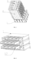
Fig. 1 is schematic structure diagram of aspecific embodiment 1 for a differential connector of the present invention. -
Fig. 2 is a schematic assembly diagram of a partial end shield and a housing component in aspecific embodiment 1 for a differential connector of the present invention. -
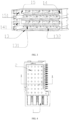
Fig. 3 is a local schematic structure diagram of a housing component in aspecific embodiment 1 for a differential connector of the present invention. -
Fig. 4 is a schematic structure diagram of aspecific embodiment 1 for a differential connector of the present invention. -
Fig. 5 is a partial sectional view along A-A inFig. 4 . -
Fig. 6 is schematic structure diagram of an end shield in aspecific embodiment 1 for a differential connector of the present invention. -
Fig. 7 is a partial sectional view of an assembly of an end shield and a housing component in aspecific embodiment 1 for a differential connector of the present invention. -
Fig. 8 is a schematic structure diagram of a shield plate inFig. 6 . -
Fig. 9 is a schematic assembly diagram of an end shield and a housing component in aspecific embodiment 2 for a differential connector of the present invention. -
Fig. 10 is a schematic structure diagram of a housing component in aspecific embodiment 2 for a differential connector of the present invention. -
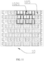
Fig. 11 is a partial sectional view of an assembly of an end shield and a housing component in aspecific embodiment 2 for a differential connector of the present invention. - The implementation manner of the present invention is further described below with reference to the accompanying drawings.
- In a
specific embodiment 1 for a differential connector of the present invention, an end of an existing differential connector is shielded by only one shield sheet, so that the shielding effect is bad. Under the limitation of the size of a housing component, a fully shielded cylindrical end shield sheet cannot be applied to an original differential module, so if the cylindrical end shield is adopted, it is necessary to change the structure of the differential module. For the purpose of reducing electromagnetic interference between differential pairs corresponding to adjacent differential modules as much as possible, the present invention designs a differential connector as follows. - As shown in
Fig. 1 to Fig. 8 , the differential connector includes ahousing component 1,differential modules 2 and afixing sheet 3 for fixing the differential modules. There are eight differential modules in the present embodiment. - Each
differential module 2 includes aninsulator 21,differential pairs 22 andground contacts 23, trace shields being provided on two sides of theinsulator 21 respectively. Thehousing component 1 includes ahousing 14, aplugging hole 11 corresponding to thedifferential pair 22 and aground contact receptacle 16 corresponding to theground contact 23 are provided on thehousing 14, and theinsulator 21 is used for combining thedifferential pair 22 and theground contact 23 together. In the present embodiment, ashield plate 24 is adopted as the trace shield, theshield plate 24 being fixed to the insulator. Anend shield 12 corresponding to a plug-in end of thedifferential pair 22 is provided on thehousing 14. - The
end shield 12 is provided with ashield groove 121 extending along a plugging direction of the plug-in end of the differential pair. In the present embodiment, the shield groove is a U-shaped shield groove. The plug-in end of the differential pair is provided in theshield groove 121. Openings of theshield grooves 121 of theend shields 12 corresponding to thedifferential pairs 22 of the same differential module face toward the same direction. The plug-in end of the differential pair is provided in theshield groove 121 so as to be isolated from a plug-in end of an adjacent differential pair. - A bottom wall, correspondingly disposed with a notch of the
shield groove 121 on theend shield 12, constitutes an adjacent-module differentialpair shield portion 122 between the differential pairs corresponding to two adjacent differential modules. Two side walls of the end shield, adjacent to the notch of the shield groove, constitute a same-module differentialpair shield portion 123 provided between adjacent differential pairs of the same differential module. - In the present embodiment, the end shields corresponding to the differential pairs of the same differential module constitute an end shield group. In the present embodiment, there are eight differential modules, there are eight corresponding end shield groups, and each end shield group is disposed along a hierarchical direction of the differential module, wherein in the hierarchical direction of the differential module, the four front end shield groups face forward, and the four rear end shield groups face backward.
- In other embodiments, the two front end shield groups face forward in the hierarchical direction of the differential module, and the six rear end shield groups face backward. Of course, the arrangement manner is not limited to this, but the following conditions should be satisfied: openings of shield grooves of only one pair of end shield groups in all pairs of adjacent end shield groups face toward opposite directions, and openings of shield grooves of the remaining pairs of adjacent end shield groups face toward the same direction. When the above conditions are satisfied, the number of the end shield groups may be two or more (excluding eight), and when there are two end shield groups, shield notches of the two end shield groups face toward opposite directions.
- The
end shield 12 is electrically connected to theshield plate 24. An endshield mounting hole 13 for mounting theend shield 12 is provided on thehousing 14. Theend shield 12 includes aninsulator layer 124 and ametal plate 125 laid on the insulator layer. Themetal plate 125 constitutes a shield layer laid on the insulator layer. In the present embodiment, in order to ensure insulated isolation between the shield layer and the differential pair, the shield layer is laid on an outer surface of the insulator layer, and the insulator layer is provided between the plugging hole and the shield layer to ensure good insulated isolation between the shield layer and the differential pair. The metal plates of the adjacent end shields are connected throughconnection ribs 126. In the present embodiment, theend shield 12 includes a portion located inside the end shield mounting hole and a portion located outside the end shield mounting hole, and the two portions are disposed along the plugging direction of the differential pair. The connection rib is connected to the portions, located outside the end shield mounting holes, on the adjacent end shields. An assembly relationship between the end shield and the housing component may be simplified as much as possible, and meanwhile, the end shield is electrically connected to the trace shield through the connection rib, thereby facilitating electrical connection between the end shield and the trace shield. - In the present embodiment, in order to facilitate mounting of the end shield and forming of a modular structure, an
integrated module 15 configured for integrating the end shields corresponding to the same differential module is provided on thehousing 14, theintegrated module 15 being of a sleeve structure. Aguide key 151 is provided on the outer side of the integrated module, and aguide groove 141 matching the guide key is provided on the housing, thereby facilitating mounting of the integrated module. - In order to facilitate mounting of the end shield and reduce the size of the end shield as much as possible, in the present embodiment, a hole wall of the end
shield mounting hole 13 includes a first mountinghole wall section 131 provided at the notch of the shield groove, and the plugginghole 11 is formed by a groove wall of the shield groove and the first mountinghole wall section 131. The endshield mounting hole 13 of theend shield 12 is provided on theintegrated module 15. In the present embodiment, the plugging hole and the end shield mounting hole share the first mounting hole wall section. - An insulated partition plate is provided between two plugging holes corresponding to the
differential pair 22. In the present embodiment, the insulated partition plate is formed by combining an L-shapedinsulated plate 132 provided on the first mounting hole wall section and located in the end shield mounting hole and an inverted L-shapedinsulated plate 127 provided on the insulator layer and being in buckled connection with the L-shaped insulated plate, and a positioning structure for positioning the end shield is also provided in the end shield mounting hole. In the present embodiment, the positioning structure includes a positioning boss in positioning fit with the end shield. - The
integrated module 15 is detachably and fixedly connected to thehousing 14. The end shield mounting hole is provided in the integrated module. In the present embodiment, in order to further reduce the size of the housing component and facilitate mounting, the end shield mounting holes corresponding to the end shields of the same differential module run through each other along the arrangement direction of the differential pairs to constitute a mounting cavity provided in the integrated module. In the present embodiment, each end shield is mounted in the mounting cavity. In other embodiments, the integrated module may also be of a plate-like structure, the end shield mounting holes are provided on the integrated module independently, and at this time, adjacent side faces of adjacent integrated modules form end shield mounting holes independent of each other. In the present embodiment, the adjacent end shields are provided at intervals, and form aground contact receptacle 16 with the integrated module. - The first mounting hole wall section is provided in the integrated module, and the L-shaped
insulated plate 132 provided in the integrated module and the positioning structure for positioning the end shield constitute a shield mounting structure provided in the integrated module and used for mounting the end shield. Corresponding partial shield mounting structures are provided on adjacent side walls of the adjacent integrated modules, and the corresponding partial shield mounting structures constitute the shield mounting structure. In the present embodiment, the positioning structure is provided on the side wall of one of the integrated modules, and the L-shaped insulated plate is provided on the adjacent side wall of the adjacent integrated module. The positioning structure and the L-shaped insulated plate on the side walls of an integrated module constitute a partial shield mounting structure, corresponding to two adjacent integrated modules, on the present integrated module. Only one side wall of the side walls of an edge integrated module is provided with the partial shield mounting structure corresponding to the adjacent integrated module. In other embodiments, the insulated partition plate may be provided on the end shield, and at this time, the shield mounting structure may be multiple positioning tables in positioning fit with the end shields. - The differential pair of the present invention is provided in the U-shaped shield groove. As shown in
Fig. 7 , for the adjacent end shield groups where the openings of the shield grooves face toward the same direction, since an electromagnetic interference path of differential pairs of adjacent differential modules is closed, the plug-in ends of the differential pairs of the adjacent differential modules cannot cause electromagnetic interference, and electromagnetic interference between diagonally adjacent differential pairs is also eliminated, thereby greatly improving the quality of signal transmission. In the same way, for the adjacent end shield groups where the openings of the shield grooves face toward opposite directions, the plug-in ends of the differential pairs of the adjacent differential modules cannot also cause electromagnetic interference. - The end shield of the present invention adopts a method of laying a shield layer on an insulator layer, which is not only suitable for laying a metal plate on an insulator layer, but also can lay a plating layer or other materials capable of absorbing or reflecting electromagnetic waves on an insulator layer. The shield layer needs to be electrically connected to the trace shield only when it is a conductive medium.
- In a
specific embodiment 2 for a differential connector of the present invention, the difference between the differential connector in the present embodiment and the differential connector described in thespecific embodiment 1 for the foregoing differential connector is only that in the present embodiment as shown inFIG. 9 , openings ofshield grooves 1021 of end shields 102 corresponding to differential pairs of each differential module face toward the same direction, the openings of eachshield groove 1021 facing toward the same arrangement direction of the differential modules. Correspondingly, as shown inFig. 10 andFig. 11 , the structures of thehousing 104, theintegrated module 105 and the endshield mounting hole 103 of thehousing component 10 are all adaptively changed. The differential pair of the present invention is provided in aU-shaped shield groove 1021, and openings of theshield grooves 1021 face toward the same direction. As shown inFig. 11 , since an electromagnetic interference path of differential pairs of adjacent differential modules is closed, the plug-in ends of the differential pairs of the adjacent differential modules cannot cause electromagnetic interference, and electromagnetic interference between diagonally adjacent differential pairs is also eliminated, thereby greatly improving the quality of signal transmission. The other partial structures are the same as those described in thespecific embodiment 1 for the foregoing differential connector, and the descriptions thereof are omitted herein. - In specific embodiments for a differential connector housing component of the present invention, the differential connector housing component has the same structure as the housing component described in the
specific embodiment
Claims (4)
- A differential connector, comprising a differential connector housing component (1) and two or more differential modules,the differential connector housing component (1) comprising a housing (14), plugging holes (11) each configured for corresponding to a plug-in end of a differential pair (22) of a differential module (2) are provided on the housing (14), and end shields (12) each corresponding to the plug-in end of the differential pair (22) are provided on the housing (14);wherein each end shield (12) is provided with a shield groove (121) extending along a plugging direction of the plug-in end of the differential pair (22) and containing the plug-in end of the differential pair (22) such that the plug-in end of the differential pair (22) is isolated from a plug-in end of an adjacent differential pair (22) of a same differential module;opening of each shield groove (121) faces toward the same direction;or, openings of shield grooves (121) of the end shields (12) corresponding to the differential pairs (22) of the same differential module face toward the same direction; the end shields (12) corresponding to the differential pairs (22) of the same differential module constitute end shield groups; when there are two end shield groups, openings of shield grooves (121) of the two end shield groups face toward opposite directions; and when there are more than two end shield groups which form pairs of adjacent end shield groups, openings of shield grooves (121) of only one pair of end shield groups in all pairs of adjacent end shield groups face toward opposite directions, and openings of shield grooves (121) of the remaining pairs of adjacent end shield groups face toward the same direction,wherein each end shield (12) comprises an insulator layer and a shield layer provided on the insulator layer; the shield layer is a conductive shield layer; wherein the shield layer is a metal plate; connection ribs are provided between metal plates of adjacent end shields (12);wherein the shield layer of each end shield corresponding to one differential pair of one differential module is electrically connected to a trace shield of said differential module through the connection ribs,wherein each differential module comprises an insulator, differential pairs (22) and ground contacts, wherein the plug-in end of each differential pair (22) is provided in each shield groove (121) and is isolated from a plug-in end of an adjacent differential pair (22) of the same differential module,wherein the trace shield is provided on at least one side of the insulator, the trace shield being provided between any two of the differential modules,wherein each differential module comprises ground contacts and the trace shield andthat the shield layer is configured to be electrically connected to the trace shield through the connection ribs,wherein each differential module comprises a plurality of differential pairs, and each plugging hole is configured for corresponding to a plug-in end of each corresponding differential pair of a differential module and that each end shield corresponds to the plug-in end of the each corresponding differential pair.
- The differential connector according to claim 1, wherein end shield mounting holes (13) are provided on the housing (14); a hole wall of each end shield mounting hole comprises a first mounting hole wall section (131) provided at a notch of each shield groove (121); the plugging hole is formed by the shield groove (121) and the first mounting hole wall section (131); and the insulator layer is provided between the plugging hole and the shield layer.
- The differential connector according to claims 2, wherein an integrated module configured for integrating end shields (12) is provided on the housing (14); a shield mounting structure adapted to each end shield (12) is provided on the integrated module; the integrated module is of a sleeve structure; the shield mounting structure is provided in the integrated module; corresponding partial shield mounting structures are provided on adjacent side walls of the adjacent integrated modules; and the corresponding partial shield mounting structures constitute the shield mounting structure.
- The differential connector according to claim 3, wherein an insulated partition plate is provided between two plugging holes (11) corresponding to the differential pairs (22); an L-shaped insulated plate is provided on the first mounting hole wall section (131); an inverted L-shaped insulated plate in buckled connection with the L-shaped insulated plate is provided on the insulator layer; and the insulated partition plate consists of the L-shaped insulated plate and the inverted L-shaped insulated plate.
Applications Claiming Priority (3)
| Application Number | Priority Date | Filing Date | Title |
|---|---|---|---|
| CN201610610603.2A CN106207637B (en) | 2016-07-29 | 2016-07-29 | Differential connector and its housing parts |
| CN201611083103.4A CN106785533B (en) | 2016-11-30 | 2016-11-30 | A kind of differential connector and its housing parts |
| PCT/CN2017/077469 WO2018018898A1 (en) | 2016-07-29 | 2017-03-21 | Differential connector and housing component thereof |
Publications (3)
| Publication Number | Publication Date |
|---|---|
| EP3447852A1 EP3447852A1 (en) | 2019-02-27 |
| EP3447852A4 EP3447852A4 (en) | 2019-05-01 |
| EP3447852B1 true EP3447852B1 (en) | 2025-02-26 |
Family
ID=61016391
Family Applications (1)
| Application Number | Title | Priority Date | Filing Date |
|---|---|---|---|
| EP17833206.0A Active EP3447852B1 (en) | 2016-07-29 | 2017-03-21 | Differential connector |
Country Status (6)
| Country | Link |
|---|---|
| US (1) | US10396503B2 (en) |
| EP (1) | EP3447852B1 (en) |
| JP (1) | JP6781826B2 (en) |
| KR (1) | KR102025217B1 (en) |
| FI (1) | FI3447852T3 (en) |
| WO (1) | WO2018018898A1 (en) |
Families Citing this family (7)
| Publication number | Priority date | Publication date | Assignee | Title |
|---|---|---|---|---|
| WO2020218845A1 (en) | 2019-04-23 | 2020-10-29 | (주)셀라토즈테라퓨틱스 | Method for regulation of selective differentiation of musculoskeletal stem cells |
| CN110323622B (en) * | 2019-07-17 | 2024-07-19 | 上海航天科工电器研究院有限公司 | Radio frequency coaxial connector with special-shaped conductive structure and manufacturing method thereof |
| CN112713429A (en) * | 2019-10-24 | 2021-04-27 | 深圳市得润电子股份有限公司 | Shielding sheet and electric connection device |
| CN112652906B (en) * | 2020-06-19 | 2022-12-02 | 东莞立讯技术有限公司 | Plugging module and cable connector |
| CN115133354B (en) * | 2022-07-07 | 2025-08-12 | 中航光电科技股份有限公司 | Shielding structure and electric connector using same |
| CN115864068A (en) * | 2022-10-24 | 2023-03-28 | 四川永贵科技有限公司 | Low-crosstalk signal pair unit, assembly thereof and high-speed cable connector |
| CN115986450B (en) * | 2023-01-03 | 2026-01-13 | 四川永贵科技有限公司 | Differential pair unit and connector for automotive application |
Citations (1)
| Publication number | Priority date | Publication date | Assignee | Title |
|---|---|---|---|---|
| WO2015013430A1 (en) * | 2013-07-23 | 2015-01-29 | Molex Incorporated | Direct backplane connector |
Family Cites Families (23)
| Publication number | Priority date | Publication date | Assignee | Title |
|---|---|---|---|---|
| DE69718948T2 (en) | 1996-08-20 | 2003-12-24 | Fci, Paris | HIGH FREQUENCY MODULAR ELECTRICAL CONNECTOR |
| US6325672B1 (en) * | 1999-10-16 | 2001-12-04 | Berg Technology, Inc. | Electrical connector with internal shield and filter |
| CA2399960A1 (en) | 2000-02-03 | 2001-08-09 | Teradyne, Inc. | Connector with shielding |
| US6293827B1 (en) * | 2000-02-03 | 2001-09-25 | Teradyne, Inc. | Differential signal electrical connector |
| US6315608B1 (en) | 2000-03-31 | 2001-11-13 | Molex Incorporated | Channel isolation shield |
| JP2003188609A (en) * | 2001-12-17 | 2003-07-04 | Japan Aviation Electronics Industry Ltd | Signal transmission board and connection structure using the signal transmission board |
| JP2005190820A (en) * | 2003-12-25 | 2005-07-14 | Fujitsu Component Ltd | Connector assembly |
| KR100610947B1 (en) | 2005-01-14 | 2006-08-09 | 엘에스전선 주식회사 | Connector with electromagnetic shielding means |
| CN100593268C (en) | 2007-05-26 | 2010-03-03 | 贵州航天电器股份有限公司 | High-speed data transmission electric connector with double shielding function |
| CN101335406B (en) | 2007-06-28 | 2011-06-08 | 贵州航天电器股份有限公司 | Integral differential pair and shielding piece dual shielding electric connector |
| US7651337B2 (en) | 2007-08-03 | 2010-01-26 | Amphenol Corporation | Electrical connector with divider shields to minimize crosstalk |
| CN201430243Y (en) | 2009-03-05 | 2010-03-24 | 富士康(昆山)电脑接插件有限公司 | Electric connector |
| US7988491B2 (en) * | 2009-12-11 | 2011-08-02 | Tyco Electronics Corporation | Electrical connector having contact modules |
| US8449329B1 (en) | 2011-12-08 | 2013-05-28 | Tyco Electronics Corporation | Cable header connector having cable subassemblies with ground shields connected to a metal holder |
| CN103594874B (en) * | 2012-08-16 | 2018-03-06 | 富士康(昆山)电脑接插件有限公司 | Electric connector and its application |
| US8840431B2 (en) | 2012-10-26 | 2014-09-23 | Tyco Electronics Corporation | Electrical connector systems |
| TWI593199B (en) * | 2013-01-08 | 2017-07-21 | 鴻騰精密科技股份有限公司 | Electrical connector |
| CN103151650B (en) | 2013-03-06 | 2015-04-29 | 华为机器有限公司 | Signal connector |
| TWI532274B (en) | 2013-05-22 | 2016-05-01 | 鴻海精密工業股份有限公司 | Electrical connector |
| CN104300313B (en) | 2013-12-05 | 2017-02-15 | 中航光电科技股份有限公司 | Full-shielding-type difference connector |
| CN105470736B (en) * | 2014-08-27 | 2019-08-30 | 富士康(昆山)电脑接插件有限公司 | Electric connector |
| CN106207637B (en) | 2016-07-29 | 2019-03-29 | 中航光电科技股份有限公司 | Differential connector and its housing parts |
| CN107871987B (en) * | 2016-09-23 | 2020-10-30 | 富士康(昆山)电脑接插件有限公司 | Electrical connector |
-
2017
- 2017-03-21 FI FIEP17833206.0T patent/FI3447852T3/en active
- 2017-03-21 WO PCT/CN2017/077469 patent/WO2018018898A1/en not_active Ceased
- 2017-03-21 JP JP2019514161A patent/JP6781826B2/en active Active
- 2017-03-21 EP EP17833206.0A patent/EP3447852B1/en active Active
- 2017-03-21 US US16/097,839 patent/US10396503B2/en active Active
- 2017-03-21 KR KR1020187032443A patent/KR102025217B1/en active Active
Patent Citations (1)
| Publication number | Priority date | Publication date | Assignee | Title |
|---|---|---|---|---|
| WO2015013430A1 (en) * | 2013-07-23 | 2015-01-29 | Molex Incorporated | Direct backplane connector |
Also Published As
| Publication number | Publication date |
|---|---|
| EP3447852A4 (en) | 2019-05-01 |
| KR102025217B1 (en) | 2019-09-25 |
| JP2019523977A (en) | 2019-08-29 |
| JP6781826B2 (en) | 2020-11-04 |
| KR20180127501A (en) | 2018-11-28 |
| EP3447852A1 (en) | 2019-02-27 |
| FI3447852T3 (en) | 2025-05-19 |
| US10396503B2 (en) | 2019-08-27 |
| WO2018018898A1 (en) | 2018-02-01 |
| US20190140400A1 (en) | 2019-05-09 |
Similar Documents
| Publication | Publication Date | Title |
|---|---|---|
| US10396503B2 (en) | Differential connector and housing component thereof | |
| US8277252B2 (en) | Electrical connector assembly | |
| US8545268B2 (en) | Electrical connector assembly | |
| US8715005B2 (en) | High speed high density connector assembly | |
| JP6236094B2 (en) | Electrical interconnection system and electrical connector thereof | |
| CN102904120B (en) | For the ground structure of plug and socket assembly | |
| EP4024624B1 (en) | Connector, connection assembly and backplane interconnection system | |
| TWI805979B (en) | Connectors and Components | |
| US8545267B2 (en) | Electrical connector assembly | |
| US8007318B1 (en) | Shielded integrated connector module | |
| US9735481B2 (en) | Daughter card assembly and communication system including the same | |
| US11005218B2 (en) | Shielding structure for an electrical connector | |
| CN106356677B (en) | Interconnection system and electric connector with resonance control | |
| US20040043661A1 (en) | Connector apparatus | |
| WO2021068967A1 (en) | Male end connector, female end connector, connector assembly, and communication device | |
| CN106207637B (en) | Differential connector and its housing parts | |
| CN106785533B (en) | A kind of differential connector and its housing parts | |
| US20180352687A1 (en) | Electromagnetic interference shielding apparatus | |
| CN212485699U (en) | Electric connector assembly | |
| US9232666B2 (en) | Cable backplane system having stiffeners | |
| US10424873B1 (en) | Electrical connector and circuit board thereof | |
| CN117239484A (en) | socket cage with absorber | |
| CN211062979U (en) | Electric connector with high interference prevention function | |
| KR101932050B1 (en) | Connector for flat cable | |
| CN111129879A (en) | Electric connector with high interference prevention function |
Legal Events
| Date | Code | Title | Description |
|---|---|---|---|
| STAA | Information on the status of an ep patent application or granted ep patent |
Free format text: STATUS: THE INTERNATIONAL PUBLICATION HAS BEEN MADE |
|
| PUAI | Public reference made under article 153(3) epc to a published international application that has entered the european phase |
Free format text: ORIGINAL CODE: 0009012 |
|
| STAA | Information on the status of an ep patent application or granted ep patent |
Free format text: STATUS: REQUEST FOR EXAMINATION WAS MADE |
|
| 17P | Request for examination filed |
Effective date: 20181122 |
|
| AK | Designated contracting states |
Kind code of ref document: A1 Designated state(s): AL AT BE BG CH CY CZ DE DK EE ES FI FR GB GR HR HU IE IS IT LI LT LU LV MC MK MT NL NO PL PT RO RS SE SI SK SM TR |
|
| AX | Request for extension of the european patent |
Extension state: BA ME |
|
| A4 | Supplementary search report drawn up and despatched |
Effective date: 20190329 |
|
| RIC1 | Information provided on ipc code assigned before grant |
Ipc: H01R 13/648 20060101AFI20190325BHEP Ipc: H01R 13/6581 20110101ALI20190325BHEP |
|
| DAV | Request for validation of the european patent (deleted) | ||
| DAX | Request for extension of the european patent (deleted) | ||
| STAA | Information on the status of an ep patent application or granted ep patent |
Free format text: STATUS: EXAMINATION IS IN PROGRESS |
|
| 17Q | First examination report despatched |
Effective date: 20200728 |
|
| REG | Reference to a national code |
Ref country code: DE Ref legal event code: R079 Free format text: PREVIOUS MAIN CLASS: H01R0013648000 Ipc: H01R0013658500 Ref country code: DE Ref legal event code: R079 Ref document number: 602017088039 Country of ref document: DE Free format text: PREVIOUS MAIN CLASS: H01R0013648000 Ipc: H01R0013658500 |
|
| RIC1 | Information provided on ipc code assigned before grant |
Ipc: H01R 13/6599 20110101ALI20210930BHEP Ipc: H01R 13/6585 20110101AFI20210930BHEP |
|
| GRAP | Despatch of communication of intention to grant a patent |
Free format text: ORIGINAL CODE: EPIDOSNIGR1 |
|
| STAA | Information on the status of an ep patent application or granted ep patent |
Free format text: STATUS: GRANT OF PATENT IS INTENDED |
|
| INTG | Intention to grant announced |
Effective date: 20240920 |
|
| GRAS | Grant fee paid |
Free format text: ORIGINAL CODE: EPIDOSNIGR3 |
|
| GRAA | (expected) grant |
Free format text: ORIGINAL CODE: 0009210 |
|
| STAA | Information on the status of an ep patent application or granted ep patent |
Free format text: STATUS: THE PATENT HAS BEEN GRANTED |
|
| AK | Designated contracting states |
Kind code of ref document: B1 Designated state(s): AL AT BE BG CH CY CZ DE DK EE ES FI FR GB GR HR HU IE IS IT LI LT LU LV MC MK MT NL NO PL PT RO RS SE SI SK SM TR |
|
| REG | Reference to a national code |
Ref country code: GB Ref legal event code: FG4D |
|
| REG | Reference to a national code |
Ref country code: CH Ref legal event code: EP |
|
| P01 | Opt-out of the competence of the unified patent court (upc) registered |
Free format text: CASE NUMBER: APP_5376/2025 Effective date: 20250131 |
|
| REG | Reference to a national code |
Ref country code: DE Ref legal event code: R096 Ref document number: 602017088039 Country of ref document: DE |
|
| REG | Reference to a national code |
Ref country code: IE Ref legal event code: FG4D |
|
| REG | Reference to a national code |
Ref country code: FI Ref legal event code: FGE |
|
| REG | Reference to a national code |
Ref country code: NL Ref legal event code: MP Effective date: 20250226 |
|
| PG25 | Lapsed in a contracting state [announced via postgrant information from national office to epo] |
Ref country code: RS Free format text: LAPSE BECAUSE OF FAILURE TO SUBMIT A TRANSLATION OF THE DESCRIPTION OR TO PAY THE FEE WITHIN THE PRESCRIBED TIME-LIMIT Effective date: 20250526 |
|
| PG25 | Lapsed in a contracting state [announced via postgrant information from national office to epo] |
Ref country code: PL Free format text: LAPSE BECAUSE OF FAILURE TO SUBMIT A TRANSLATION OF THE DESCRIPTION OR TO PAY THE FEE WITHIN THE PRESCRIBED TIME-LIMIT Effective date: 20250226 |
|
| PG25 | Lapsed in a contracting state [announced via postgrant information from national office to epo] |
Ref country code: ES Free format text: LAPSE BECAUSE OF FAILURE TO SUBMIT A TRANSLATION OF THE DESCRIPTION OR TO PAY THE FEE WITHIN THE PRESCRIBED TIME-LIMIT Effective date: 20250226 |
|
| REG | Reference to a national code |
Ref country code: LT Ref legal event code: MG9D |
|
| PG25 | Lapsed in a contracting state [announced via postgrant information from national office to epo] |
Ref country code: NO Free format text: LAPSE BECAUSE OF FAILURE TO SUBMIT A TRANSLATION OF THE DESCRIPTION OR TO PAY THE FEE WITHIN THE PRESCRIBED TIME-LIMIT Effective date: 20250526 Ref country code: IS Free format text: LAPSE BECAUSE OF FAILURE TO SUBMIT A TRANSLATION OF THE DESCRIPTION OR TO PAY THE FEE WITHIN THE PRESCRIBED TIME-LIMIT Effective date: 20250626 |
|
| PG25 | Lapsed in a contracting state [announced via postgrant information from national office to epo] |
Ref country code: NL Free format text: LAPSE BECAUSE OF FAILURE TO SUBMIT A TRANSLATION OF THE DESCRIPTION OR TO PAY THE FEE WITHIN THE PRESCRIBED TIME-LIMIT Effective date: 20250226 |
|
| PG25 | Lapsed in a contracting state [announced via postgrant information from national office to epo] |
Ref country code: HR Free format text: LAPSE BECAUSE OF FAILURE TO SUBMIT A TRANSLATION OF THE DESCRIPTION OR TO PAY THE FEE WITHIN THE PRESCRIBED TIME-LIMIT Effective date: 20250226 |
|
| PG25 | Lapsed in a contracting state [announced via postgrant information from national office to epo] |
Ref country code: LV Free format text: LAPSE BECAUSE OF FAILURE TO SUBMIT A TRANSLATION OF THE DESCRIPTION OR TO PAY THE FEE WITHIN THE PRESCRIBED TIME-LIMIT Effective date: 20250226 Ref country code: PT Free format text: LAPSE BECAUSE OF FAILURE TO SUBMIT A TRANSLATION OF THE DESCRIPTION OR TO PAY THE FEE WITHIN THE PRESCRIBED TIME-LIMIT Effective date: 20250626 |
|
| PG25 | Lapsed in a contracting state [announced via postgrant information from national office to epo] |
Ref country code: BG Free format text: LAPSE BECAUSE OF FAILURE TO SUBMIT A TRANSLATION OF THE DESCRIPTION OR TO PAY THE FEE WITHIN THE PRESCRIBED TIME-LIMIT Effective date: 20250226 Ref country code: GR Free format text: LAPSE BECAUSE OF FAILURE TO SUBMIT A TRANSLATION OF THE DESCRIPTION OR TO PAY THE FEE WITHIN THE PRESCRIBED TIME-LIMIT Effective date: 20250527 |
|
| REG | Reference to a national code |
Ref country code: AT Ref legal event code: MK05 Ref document number: 1771628 Country of ref document: AT Kind code of ref document: T Effective date: 20250226 |
|
| PG25 | Lapsed in a contracting state [announced via postgrant information from national office to epo] |
Ref country code: SE Free format text: LAPSE BECAUSE OF FAILURE TO SUBMIT A TRANSLATION OF THE DESCRIPTION OR TO PAY THE FEE WITHIN THE PRESCRIBED TIME-LIMIT Effective date: 20250226 |
|
| PG25 | Lapsed in a contracting state [announced via postgrant information from national office to epo] |
Ref country code: SM Free format text: LAPSE BECAUSE OF FAILURE TO SUBMIT A TRANSLATION OF THE DESCRIPTION OR TO PAY THE FEE WITHIN THE PRESCRIBED TIME-LIMIT Effective date: 20250226 |
|
| PG25 | Lapsed in a contracting state [announced via postgrant information from national office to epo] |
Ref country code: DK Free format text: LAPSE BECAUSE OF FAILURE TO SUBMIT A TRANSLATION OF THE DESCRIPTION OR TO PAY THE FEE WITHIN THE PRESCRIBED TIME-LIMIT Effective date: 20250226 |
|
| PG25 | Lapsed in a contracting state [announced via postgrant information from national office to epo] |
Ref country code: IT Free format text: LAPSE BECAUSE OF FAILURE TO SUBMIT A TRANSLATION OF THE DESCRIPTION OR TO PAY THE FEE WITHIN THE PRESCRIBED TIME-LIMIT Effective date: 20250226 |
|
| PG25 | Lapsed in a contracting state [announced via postgrant information from national office to epo] |
Ref country code: AT Free format text: LAPSE BECAUSE OF FAILURE TO SUBMIT A TRANSLATION OF THE DESCRIPTION OR TO PAY THE FEE WITHIN THE PRESCRIBED TIME-LIMIT Effective date: 20250226 |
|
| PG25 | Lapsed in a contracting state [announced via postgrant information from national office to epo] |
Ref country code: EE Free format text: LAPSE BECAUSE OF FAILURE TO SUBMIT A TRANSLATION OF THE DESCRIPTION OR TO PAY THE FEE WITHIN THE PRESCRIBED TIME-LIMIT Effective date: 20250226 Ref country code: CZ Free format text: LAPSE BECAUSE OF FAILURE TO SUBMIT A TRANSLATION OF THE DESCRIPTION OR TO PAY THE FEE WITHIN THE PRESCRIBED TIME-LIMIT Effective date: 20250226 |
|
| REG | Reference to a national code |
Ref country code: CH Ref legal event code: H13 Free format text: ST27 STATUS EVENT CODE: U-0-0-H10-H13 (AS PROVIDED BY THE NATIONAL OFFICE) Effective date: 20251023 |
|
| PG25 | Lapsed in a contracting state [announced via postgrant information from national office to epo] |
Ref country code: RO Free format text: LAPSE BECAUSE OF FAILURE TO SUBMIT A TRANSLATION OF THE DESCRIPTION OR TO PAY THE FEE WITHIN THE PRESCRIBED TIME-LIMIT Effective date: 20250226 |
|
| PG25 | Lapsed in a contracting state [announced via postgrant information from national office to epo] |
Ref country code: SK Free format text: LAPSE BECAUSE OF FAILURE TO SUBMIT A TRANSLATION OF THE DESCRIPTION OR TO PAY THE FEE WITHIN THE PRESCRIBED TIME-LIMIT Effective date: 20250226 |
|
| PG25 | Lapsed in a contracting state [announced via postgrant information from national office to epo] |
Ref country code: LU Free format text: LAPSE BECAUSE OF NON-PAYMENT OF DUE FEES Effective date: 20250321 |
|
| REG | Reference to a national code |
Ref country code: DE Ref legal event code: R097 Ref document number: 602017088039 Country of ref document: DE |
|
| REG | Reference to a national code |
Ref country code: BE Ref legal event code: MM Effective date: 20250331 |
|
| PG25 | Lapsed in a contracting state [announced via postgrant information from national office to epo] |
Ref country code: MC Free format text: LAPSE BECAUSE OF FAILURE TO SUBMIT A TRANSLATION OF THE DESCRIPTION OR TO PAY THE FEE WITHIN THE PRESCRIBED TIME-LIMIT Effective date: 20250226 |
|
| PLBE | No opposition filed within time limit |
Free format text: ORIGINAL CODE: 0009261 |
|
| STAA | Information on the status of an ep patent application or granted ep patent |
Free format text: STATUS: NO OPPOSITION FILED WITHIN TIME LIMIT |
|
| PG25 | Lapsed in a contracting state [announced via postgrant information from national office to epo] |
Ref country code: BE Free format text: LAPSE BECAUSE OF NON-PAYMENT OF DUE FEES Effective date: 20250331 |
|
| PG25 | Lapsed in a contracting state [announced via postgrant information from national office to epo] |
Ref country code: CH Free format text: LAPSE BECAUSE OF NON-PAYMENT OF DUE FEES Effective date: 20250331 |
|
| PG25 | Lapsed in a contracting state [announced via postgrant information from national office to epo] |
Ref country code: IE Free format text: LAPSE BECAUSE OF NON-PAYMENT OF DUE FEES Effective date: 20250321 |
|
| 26N | No opposition filed |
Effective date: 20251127 |
|
| PGFP | Annual fee paid to national office [announced via postgrant information from national office to epo] |
Ref country code: GB Payment date: 20260317 Year of fee payment: 10 |
|
| PGFP | Annual fee paid to national office [announced via postgrant information from national office to epo] |
Ref country code: DE Payment date: 20260326 Year of fee payment: 10 |
|
| PGFP | Annual fee paid to national office [announced via postgrant information from national office to epo] |
Ref country code: FI Payment date: 20260317 Year of fee payment: 10 |
|
| PGFP | Annual fee paid to national office [announced via postgrant information from national office to epo] |
Ref country code: FR Payment date: 20260319 Year of fee payment: 10 |