EP3447825B1 - Electrolyte mixing apparatus for battery capable of increasing flow velocity of electrolyte - Google Patents
Electrolyte mixing apparatus for battery capable of increasing flow velocity of electrolyte Download PDFInfo
- Publication number
- EP3447825B1 EP3447825B1 EP17209927.7A EP17209927A EP3447825B1 EP 3447825 B1 EP3447825 B1 EP 3447825B1 EP 17209927 A EP17209927 A EP 17209927A EP 3447825 B1 EP3447825 B1 EP 3447825B1
- Authority
- EP
- European Patent Office
- Prior art keywords
- electrolyte
- wall
- specific gravity
- circulation path
- guide plate
- Prior art date
- Legal status (The legal status is an assumption and is not a legal conclusion. Google has not performed a legal analysis and makes no representation as to the accuracy of the status listed.)
- Active
Links
Images







Classifications
-
- H—ELECTRICITY
- H01—ELECTRIC ELEMENTS
- H01M—PROCESSES OR MEANS, e.g. BATTERIES, FOR THE DIRECT CONVERSION OF CHEMICAL ENERGY INTO ELECTRICAL ENERGY
- H01M10/00—Secondary cells; Manufacture thereof
- H01M10/06—Lead-acid accumulators
- H01M10/12—Construction or manufacture
-
- B—PERFORMING OPERATIONS; TRANSPORTING
- B01—PHYSICAL OR CHEMICAL PROCESSES OR APPARATUS IN GENERAL
- B01F—MIXING, e.g. DISSOLVING, EMULSIFYING OR DISPERSING
- B01F23/00—Mixing according to the phases to be mixed, e.g. dispersing or emulsifying
- B01F23/40—Mixing liquids with liquids; Emulsifying
- B01F23/45—Mixing liquids with liquids; Emulsifying using flow mixing
-
- B—PERFORMING OPERATIONS; TRANSPORTING
- B01—PHYSICAL OR CHEMICAL PROCESSES OR APPARATUS IN GENERAL
- B01F—MIXING, e.g. DISSOLVING, EMULSIFYING OR DISPERSING
- B01F35/00—Accessories for mixers; Auxiliary operations or auxiliary devices; Parts or details of general application
- B01F35/50—Mixing receptacles
- B01F35/53—Mixing receptacles characterised by the configuration of the interior, e.g. baffles for facilitating the mixing of components
- B01F35/531—Mixing receptacles characterised by the configuration of the interior, e.g. baffles for facilitating the mixing of components with baffles, plates or bars on the wall or the bottom
-
- H—ELECTRICITY
- H01—ELECTRIC ELEMENTS
- H01M—PROCESSES OR MEANS, e.g. BATTERIES, FOR THE DIRECT CONVERSION OF CHEMICAL ENERGY INTO ELECTRICAL ENERGY
- H01M10/00—Secondary cells; Manufacture thereof
- H01M10/42—Methods or arrangements for servicing or maintenance of secondary cells or secondary half-cells
- H01M10/4214—Arrangements for moving electrodes or electrolyte
-
- H—ELECTRICITY
- H01—ELECTRIC ELEMENTS
- H01M—PROCESSES OR MEANS, e.g. BATTERIES, FOR THE DIRECT CONVERSION OF CHEMICAL ENERGY INTO ELECTRICAL ENERGY
- H01M10/00—Secondary cells; Manufacture thereof
- H01M10/42—Methods or arrangements for servicing or maintenance of secondary cells or secondary half-cells
- H01M10/4242—Regeneration of electrolyte or reactants
-
- H—ELECTRICITY
- H01—ELECTRIC ELEMENTS
- H01M—PROCESSES OR MEANS, e.g. BATTERIES, FOR THE DIRECT CONVERSION OF CHEMICAL ENERGY INTO ELECTRICAL ENERGY
- H01M50/00—Constructional details or processes of manufacture of the non-active parts of electrochemical cells other than fuel cells, e.g. hybrid cells
- H01M50/70—Arrangements for stirring or circulating the electrolyte
-
- H—ELECTRICITY
- H01—ELECTRIC ELEMENTS
- H01M—PROCESSES OR MEANS, e.g. BATTERIES, FOR THE DIRECT CONVERSION OF CHEMICAL ENERGY INTO ELECTRICAL ENERGY
- H01M2300/00—Electrolytes
- H01M2300/0002—Aqueous electrolytes
- H01M2300/0005—Acid electrolytes
- H01M2300/0011—Sulfuric acid-based
-
- Y—GENERAL TAGGING OF NEW TECHNOLOGICAL DEVELOPMENTS; GENERAL TAGGING OF CROSS-SECTIONAL TECHNOLOGIES SPANNING OVER SEVERAL SECTIONS OF THE IPC; TECHNICAL SUBJECTS COVERED BY FORMER USPC CROSS-REFERENCE ART COLLECTIONS [XRACs] AND DIGESTS
- Y02—TECHNOLOGIES OR APPLICATIONS FOR MITIGATION OR ADAPTATION AGAINST CLIMATE CHANGE
- Y02E—REDUCTION OF GREENHOUSE GAS [GHG] EMISSIONS, RELATED TO ENERGY GENERATION, TRANSMISSION OR DISTRIBUTION
- Y02E60/00—Enabling technologies; Technologies with a potential or indirect contribution to GHG emissions mitigation
- Y02E60/10—Energy storage using batteries
-
- Y—GENERAL TAGGING OF NEW TECHNOLOGICAL DEVELOPMENTS; GENERAL TAGGING OF CROSS-SECTIONAL TECHNOLOGIES SPANNING OVER SEVERAL SECTIONS OF THE IPC; TECHNICAL SUBJECTS COVERED BY FORMER USPC CROSS-REFERENCE ART COLLECTIONS [XRACs] AND DIGESTS
- Y02—TECHNOLOGIES OR APPLICATIONS FOR MITIGATION OR ADAPTATION AGAINST CLIMATE CHANGE
- Y02P—CLIMATE CHANGE MITIGATION TECHNOLOGIES IN THE PRODUCTION OR PROCESSING OF GOODS
- Y02P70/00—Climate change mitigation technologies in the production process for final industrial or consumer products
- Y02P70/50—Manufacturing or production processes characterised by the final manufactured product
Definitions
- the present invention generally relates to an electrolyte mixing apparatus for a battery capable of increasing a flow velocity of an electrolyte.
- a battery is a device generating an electromotive force by an internal chemical action.
- a battery is capable of being repeatedly charged and discharged, and therefore, it is generally called a secondary battery.
- a positive electrode is composed of lead dioxide (PbO2)
- a negative electrode is composed of spongy lead (Pb)
- an electrolyte is a diluted sulfuric acid (H2SO4).
- Such a battery makes current flow using a potential difference between the positive electrode and the negative electrode, each one consisting of the lead dioxide and the lead respectively, whereby power is generated for operating a load.
- a casing of the battery is filled with the electrolyte and a surface of the filled electrolyte is higher than upper ends of pole plates fixed in the casing of the battery.
- electrolyte stratification occurs wherein the electrolyte becomes layered according to specific gravity so that lower specific gravity electrolyte is disposed at an upper layer while higher specific gravity electrolyte sinks and is disposed at a bottom layer.
- Such conventional electrolyte stratification means a separation of the electrolyte into multiple layers according to specific gravities thereof. This is a general phenomenon caused by a difference in specific gravities under no convection state.
- a pole plate group restricts a flow of the electrolyte so that upper and lower portions of the electrolyte cannot be mixed smoothly with each other, thereby the electrolyte stratification occurs. That is, in the conventional battery, the electrolyte stratification makes the lower specific gravity electrolyte be disposed at the upper portion of the pole plate assembly, thereby corrosion of the upper portion of the pole plates is accelerated since the sulfuric acid solution of the lower specific gravity electrolyte has a relatively low concentration.
- a terminal voltage of the battery may be indicated higher than an actual degree of charge.
- Such overvoltage may cause insufficient charge in a typical charging method of vehicles or other machines in which charge voltage is adjusted to a predetermined voltage.
- continuous use of the battery in the insufficient charging state also accelerates sulfation of the pole plates, thus reducing the lifetime of the battery.
- An apparatus for mixing higher specific gravity electrolyte and lower specific gravity electrolyte according to a flow of an electrolyte in a battery is provided in the related art.
- a conventional apparatus for mixing an electrolyte in a battery has large amount of the electrolyte therein, thus the electrolyte should be mixed in a short period of time.
- the conventional apparatus for mixing an electrolyte in a battery has a problem with time of mixing the higher specific gravity electrolyte and the lower specific gravity electrolyte, for example, in case of the conventional apparatus is applied to such a large capacity battery, since a flow of an electrolyte up and down takes a long time.
- EP 2 660 894 A1 discloses mixing electrolyte of batteries.
- the present invention has been made keeping in mind the above problems occurring in the related art, and the present invention is intended to provide an electrolyte mixing apparatus for a battery capable of increasing a flow velocity of an electrolyte which is configured to increase a flow velocity of an electrolyte separated into higher specific gravity electrolyte and lower specific gravity electrolyte so as to mix the higher specific gravity electrolyte and the lower specific gravity electrolyte in a short period of time.
- the present invention is intended to provide an electrolyte mixing apparatus for a battery capable of increasing a flow velocity of an electrolyte which is configured to efficiently mix higher specific gravity electrolyte and lower specific gravity electrolyte in a large capacity battery applied to heavy vehicles (buses or trucks).
- the present invention provides the electrolyte mixing apparatus for a battery of claim 1, as well as exemplary embodiments described hereinbelow.
- an electrolyte mixing apparatus for a battery capable of increasing a flow velocity of an electrolyte
- the apparatus including,: a guide plate provided between an inner wall surface of a battery casing and a pole plate assembly so as to provide a passage to deliver the higher specific gravity electrolyte upwards by inertia, and to deliver downwards a mixed electrolyte provided at an upper portion; and at least one mixing container mixing the higher specific gravity electrolyte, introduced through the passage provided on the guide plate, with the lower specific gravity electrolyte introduced into the upper portion, and discharging the mixed electrolyte, according to a direction of inertia
- the mixing container includes: a receiving portion providing a space in a top portion of the guide plate for mixing the lower specific gravity electrolyte with the higher specific gravity electrolyte, and providing an inlet/outlet groove for introducing the lower specific gravity electrolyte and discharging the mixed electrolyte according to a direction of in
- the present invention is intended to provide an electrolyte mixing apparatus for a battery capable of increasing a flow velocity of an electrolyte which is configured to efficiently mix higher specific gravity electrolyte and lower specific gravity electrolyte in a large capacity battery applied to heavy vehicles (buses or trucks).
- the present invention provides exemplary embodiments described hereinbelow.
- an electrolyte mixing apparatus for a battery capable of increasing a flow velocity of an electrolyte
- the apparatus including,: a guide plate provided between an inner wall surface of a battery casing and a pole plate assembly so as to provide a passage to deliver the higher specific gravity electrolyte upwards by inertia, and to deliver downwards a mixed electrolyte provided at an upper portion; and at least one mixing container mixing the higher specific gravity electrolyte, introduced through the passage provided on the guide plate, with the lower specific gravity electrolyte introduced into the upper portion, and discharging the mixed electrolyte, according to a direction of inertia
- the mixing container includes: a receiving portion providing a space in a top portion of the guide plate for mixing the lower specific gravity electrolyte with the higher specific gravity electrolyte, and providing an inlet/outlet groove for introducing the lower specific gravity electrolyte and discharging the mixed electrolyte according to a direction of in
- the electrolyte mixing apparatus for a battery according to the present invention can increase the flow velocity of both the lower specific gravity electrolyte and the higher specific gravity electrolyte, introduced into the mixing apparatus by inertia, thereby efficiently mixing the electrolyte in a short period of time.
- the present invention is capable of increasing a flow velocity of the electrolyte, it is suitable for a large capacity battery.
- pole plate assembly 2 strap 3: mixing apparatus 4: casing A: higher specific gravity electrolyte B: lower specific gravity electrolyte C: mixed electrolyte 100: guide plate 110: incision portion 200, 200': mixing container 210: receiving portion 211: partition wall 21 1a: outer partition wall 211b: inner partition wall 212: extension wall 213: bottom surface 220: labyrinth portion 221, 222: labyrinth wall 221a, 222a: convergence wall 221b, 222b: conversion wall 221c, 222c: expansion wall 223: circulation port 230: inclined wall 240: inlet/outlet groove 251: first circulation path 252: second circulation path 253: third circulation path 300: connecting container 310, 320, 330: connecting portion 341, 342: sidewall 351, 352, 353: front wall 400: guide bar 510: first guide passage 520: second guide passage
- FIGS. 1A and 1B are schematic diagrams describing a summary of an electrolyte mixing apparatus for a battery capable of increasing a flow velocity of an electrolyte according to the present invention.
- an electrolyte mixing apparatus 3 mixes and discharges an electrolyte by inertia, which is generated according to an operation of vehicles (for example, acceleration, steady speed, deceleration, stopped).
- the battery may consist of a casing 4, a pole plate assembly 1, and a strap 2.
- the casing 4 provides a place for containing an electrolyte, the pole plate assembly 1, and the strap 2 therein.
- the electrolyte is dispersed into higher specific gravity electrolyte A and lower specific gravity electrolyte B, and each is disposed at a bottom portion and at an upper portion respectively.
- the pole plate assembly 1 consists of multiple positive and negative plates densely arranged alternately, and the strap 2 connects the positive and negative pole plates to each other such that an electric current can flow therebetween.
- the casing 4, the pole plate assembly 1, and the strap 2 are generally applied by using known configurations, and thus will not be described here.
- the electrolyte mixing apparatus 3 is provided between the pole plate assembly 1 and an inner wall surface of the battery casing 4, and mixes and discharges the electrolyte moved by the inertia.
- the inertia when the inertia is applied to the electrolyte in one direction, the lower specific gravity electrolyte B disposed at an upper portion of the casing 4 is introduced into an upper portion of the electrolyte mixing apparatus 3, and the higher specific gravity electrolyte A disposed at a bottom portion of the casing 4 is introduced into the upper portion of the electrolyte mixing apparatus 3 through a passage provided between the inner wall surface of the casing 4.
- the electrolyte is introduced into the electrolyte mixing apparatus 3 due to kinetic energy generated by such inertia, so a height difference is generated.
- the electrolyte mixing apparatus 3 mixes the higher specific gravity electrolyte A moved by the inertia with the lower specific gravity electrolyte B introduced from the upper portion, and then discharges the electrolyte so as to remove the height difference.
- the electrolyte mixing apparatus 3 discharges mixed electrolyte C in such a process, the height difference is removed and the electrolyte becomes a horizontal surface so that the electrolyte mixing apparatus 3 becomes a state of receiving the mixed electrolyte C therein.
- the electrolyte is moved to an opposite direction of FIG. 1A by kinetic energy applied in an opposite direction, so a height difference is generated in an opposite side.
- the mixed electrolyte in the electrolyte mixing apparatus 3 is quickly discharged to the upper side and the bottom side due to the height difference.
- the electrolyte mixing apparatus 3 repeatedly mixes and discharges the higher and the lower specific gravity electrolytes A and B while the height difference of electrolyte by the inertia is generated and removed.
- the present invention increases the flow velocity of the higher specific gravity electrolyte A moved from bottom portion of the casing 4 so as to mix large amounts of higher specific gravity electrolyte A and lower specific gravity electrolyte B during such generation and removal processes of the height difference.
- FIG. 2 is a front perspective view
- FIG. 3 is a rear perspective view
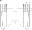
- FIG. 4 is a rear view
- FIG. 5 is a side view
- FIG. 6 is a plan view illustrating an electrolyte mixing apparatus for a battery capable of increasing a flow velocity of an electrolyte according to the present invention
- FIG. 7 illustrates a circulating path.
- an electrolyte mixing apparatus 3 for a battery capable of increasing a flow velocity of an electrolyte includes a guide plate 100 which is provided between an inner wall surface of a battery casing 4 so as to provide a passage, at least one mixing container 200 mixing an electrolyte, a connecting container 300 connecting and supporting between mixing containers 200, and a guide bar 400 increasing a flow velocity at the guide plate 100.
- the guide plate 100 that is an upright panel provides passages between it and the inner wall surface of the casing 4.
- the passages include a passage that delivers the higher specific gravity electrolyte A disposed at the bottom portion upwards, and a passage that delivers a mixed electrolyte C mixed at the mixing container 200 downwards.
- the passage for delivering the higher specific gravity electrolyte A upwards and the passage for delivering the mixed electrolyte C downwards may be configured as one passage or may be configured separately.
- the guide plate 100 may include an incision portion 110, which is cut in the middle bottom portion of the guide plate 100 so as to deliver the higher specific gravity electrolyte A from the middle portion of the guide plate 100 to the connecting container 300.
- the incision portion 110 is cut in the middle bottom portion of the guide plate 100 and provides a path for delivering the higher specific gravity electrolyte A disposed at the bottom portion.
- the incision portion 110 may be provided for removing a resistance caused by residues formed by a hot melt adhesive introduced to bond the pole plate assembly 1 of the battery, or removing a resistance by a protrusion on the wall surface of the casing 4.
- the incision portion 110 may provide a space for receiving a protrusion or residues when the protrusion on the wall surface of the casing 4 and the residues by the hot melt adhesive exist. That is, when the guide plate 100 is inserted between the wall surface of the casing 4 and the pole plate assembly 1 and the protrusion exists on the wall surface of the casing 4, the protrusion may be received in the space provided by the incision portion 110 and the resistance by the protrusion on the wall surface of the casing 4 can be removed.
- the mixing container 200 provides a passage to circulate the introduced higher specific gravity electrolyte A and lower specific gravity electrolyte B so as to mix the higher specific gravity electrolyte A and the lower specific gravity electrolyte B together at the upper portion of the guide plate 100.
- the mixing container 200 is configured to form a bent bottom surface 213 at a top portion of the guide plate 100, and includes a receiving portion 210 provided with a space between opposite wall surfaces, a labyrinth portion 220 circulating the electrolyte inside the receiving portion 210, an inclined wall 230 extending slantingly from a front surface of the receiving portion 210, and an inlet/outlet groove 240 of introducing the lower specific gravity electrolyte B disposed at an upper portion and discharging the mixed electrolyte C.
- the receiving portion 210 includes the bottom surface 213 bent from the top portion of the upright guide plate 100, opposite partition walls 211 separating spaces standing at opposite sides, an upward step 214 extending upward from the bottom surface 213, and an extension wall 212 extending from the partition wall 211 and providing the labyrinth portion 220 and circulation paths.
- the partition walls 211 are a pair of walls spaced apart from each other, and define a space for providing the labyrinth portion 220 therein. At this point, ends of the partition walls 211 protrude towards the wall surface of the casing 4 so as to provide a passage between the partition walls 211.
- the higher specific gravity electrolyte A disposed at the bottom portion flows to the receiving portion 210 providing the labyrinth portion 220 therein through the passage defined between the partition walls 211.
- the upward step 214 extends upward from the bottom surface 213 and supports the labyrinth portion 220.
- the upward step 214 since the upward step 214 is placed above the bottom surface 213, the upward step 214 has a configuration that can be close to the strap 2 at a top portion of the pole plate assembly 1.
- the strap 2 connects multiple positive and negative pole plates such that an electric current can flow therebetween.
- the upward step 214 is configured to have a structure corresponding to shapes of the strap 2 and the pole plate assembly 1, thereby enabling easy installing of the pole plate assembly 1 to which the strap 2 is connected.
- Such a structure of the upward step 214 realizes an easy installation of the mixing apparatus 3 in the casing 4.
- the extension wall 212 extends to be bent from an outer partition wall 211a disposed at an outer side among the pair of the partition walls 211.
- the extension wall 212 is upright and spaced apart from the labyrinth portion 220 so as to provide a passage for allowing a flow of the electrolyte between the extension wall 212 and the labyrinth portion 220.
- the extension wall 212 is configured to form an outer wall of the upward step 214.
- the inclined wall 230 slantingly extends upward from the end of the upward step 214, wherein the upward step 214 is surrounded by the extension wall 212 and an inner partition wall 211b, and extends upward from the bottom surface 213 of the receiving portion 210. At this point, the inclined wall 230 slantingly extends upward and is spaced apart from the ends of the extension wall 212 and the inner partition wall 211b so as to provide the inlet/outlet groove 240.
- the inlet/outlet groove 240 is a groove spaced apart from the ends of the inclined wall 230, the extension wall 212, and the inner partition wall 211b.
- the lower specific gravity electrolyte B disposed at the upper portion of the casing 4 is introduced and the mixed electrolyte C is discharged, through the inlet/outlet groove 240.
- the labyrinth portion 220 includes opposite labyrinth walls 221 and 222 which are upright and face each other in the receiving portion 210, and a circulation port 223 providing an inlet/outlet between the pair of labyrinth walls 221 and 222.
- the pair of the labyrinth walls 221 and 222 includes a first labyrinth wall 221 extending while being spaced apart from the outer partition wall 211a and the extension wall 212, and a second labyrinth wall 222 extending while being spaced apart from the inner partition wall 211b.
- the first labyrinth wall 221 defines a first circulation path 251
- the second labyrinth wall 222 defines a second circulation path 252
- a third circulation path 253 is defined between the first labyrinth wall 221 and the second labyrinth wall 222.
- the circulation of electrolyte in the first circulation path 251 to the third circulation path 253 is different according to a direction of inertia. That is, when the inertia is applied to the direction in which the electrolyte is introduced, the first circulation path 251 and the second circulation path 252 circulate the lower specific gravity electrolyte B introduced through the inlet/outlet groove 240 and discharge the lower specific gravity electrolyte B into the third circulation path 253, and the third circulation path 253 circulates the higher specific gravity electrolyte A introduced through the guide plate 100 and discharges the higher specific gravity electrolyte A into the first circulation path 251 and the second circulation path 252.
- the first circulation path 251 and the second circulation path 252 mix the lower specific gravity electrolyte B and the higher specific gravity electrolyte A together, and then discharge the mixed electrolyte into the third circulation path 253.
- the mixed electrolyte and the higher specific gravity electrolyte A are mixed together.
- the mixed electrolyte C as described above is discharged when the inertia is applied to the opposite direction or when the height difference generated by the inertia is removed.
- the mixed electrolyte C which is a result of mixing the lower specific gravity electrolyte B and the higher specific gravity electrolyte A circulates to be discharged outside the mixing container 200.
- the first circulation path 251 and the second circulation path 252 guide the mixed electrolyte C to the inlet/outlet groove 240
- the third circulation path 253 guides the mixed electrolyte C to the guide plate 100.
- first labyrinth wall 221 and the second labyrinth wall 222 have the same structure, so the first labyrinth wall 221 will be described as an example.
- the first labyrinth wall 221 includes a convergence wall 221a spaced apart from the outer partition wall 211a, a conversion wall 221b bent from the convergence wall 221a, and a expansion wall 221c bent from the conversion wall 221b.
- the convergence wall 221a is upright at the bottom surface 213 and slantingly extends.
- the convergence wall 221a slantingly extends such that a gap between the convergence wall 221a and the outer partition wall 211a becomes narrower in a direction toward the guide plate 100 (an exit side), thereby forming an exit of the first circulation path 251 (or the second circulation path 252).
- the conversion wall 221b is bent from the end of the convergence wall 221a. At this point, the conversion wall 221b is formed in a similar structure with a structure of the extension wall 212 connected to the partition wall 211. Such structure is to form the first circulation path 251 capable of switching the flow direction of the electrolyte introduced through the convergence wall 221a or the expansion wall 221c.
- the expansion wall 221c extends and is bent from the conversion wall 221b in the same direction as that of the extension wall 212, and forms the first circulation path 251 (or the second circulation path 252).
- the expansion wall 221c has a gap wider than gaps between the convergence wall 221a and the partition wall 211, and between the conversion wall 221b and the partition wall 211.
- the end of the expansion wall 221c is spaced apart from the inclined wall 230, thereby increasing the flow velocity of the higher specific gravity electrolyte A introduced from the third circulation path 253.
- the end of the expansion wall 221c spaced apart from the inclined wall 230 may be connected with the inlet/outlet groove 240.
- the first circulation path 251 and the second circulation path 252 defined by the first labyrinth wall 221 and the second labyrinth wall 222 are capable of increasing the flow velocity of the electrolyte since the exit side (between the convergence wall 221a and the partition wall 211) has the narrowest gap.
- the third circulation path 253 is capable of increasing the flow velocity of the higher specific gravity electrolyte A since an exit side, the circulation port 223, is configured to be narrower than an entrance side connecting the guide plate 100. Additionally, the flow velocities of the higher specific gravity electrolyte A and the mixed electrolyte C introduced from the third circulation path 253 into the first circulation path 251, and from the third circulation path 253 into the second circulation path 252 can be increased as passing the narrow gap between the expansion wall 221c and the inclined wall 230.
- the guide bar 400 extends in a longitudinal direction on a surface of the guide plate 100 between the ends of the opposite partition walls 211, and separates a first guide passage 510 and a second guide passage 520 from each other.
- the guide bar 400 slantingly extends from the bottom of the guide plate 100 in a direction toward the connecting container 300.
- the first guide passage 510 becomes enlarged gradually from a starting point (the bottom of the guide plate 100) to an end point (the entrance of the third circulation path 253) reaching the bottom surface 213, while the second guide passage 520 becomes narrow gradually.
- Such a difference in the shape of the passages is to deliver the higher specific gravity electrolyte A disposed at the bottom portion of the casing 4 to the first circulation path 251 and the second circulation path 252 through the third circulation path 253. That is, the first guide passage 510 extending to the third circulation path 253 is enlarged so as to deliver a large amount of the higher specific gravity electrolyte A introduced into the mixing container 200 from the bottom portion of the casing 4.
- a top of the second guide passage 520 is close to a starting point of the first circulation path 251, as a width of the second guide passage 520 becomes narrow, thus the flow velocity of the higher specific gravity electrolyte A flowing therein increases.
- the higher specific gravity electrolyte A having such higher velocity bumps into the mixed electrolyte C discharged from the first circulation path 251, thereby being guided to flow to the third circulation path 253.
- the second guide passage 520 increases the flow velocity of the higher specific gravity electrolyte A moved from the bottom portion of the casing 4, thus guiding a flow direction of the mixed electrolyte C to the third circulation path 253, wherein the mixed electrolyte C is the result of mixing the lower specific gravity electrolyte B discharged from the first circulation path 251 with the higher specific gravity electrolyte A together.
- the higher specific gravity electrolyte A disposed at the bottom portion of the casing 4 flows to the third circulation path 253 of the mixing container 200 through the first guide passage 510 and the second guide passage 520, and the higher specific gravity electrolyte A is mixed with the lower specific gravity electrolyte B introduced from the first circulation path 251 and the second circulation path 252 through the inlet/outlet groove 240 and circulates together with the lower specific gravity electrolyte B.
- the connecting container 300 is configured to divide multiple spaces between opposite mixing containers 200 so as to receive the higher specific gravity electrolyte A introduced from the bottom portion of the casing 4.
- the connecting container 300 is divided into first to third connecting portions 310 to 330 as a first side wall 341 and a second side wall 342 are configured to be spaced apart from each other at a position between the first mixing container 200 and a second mixing container 200'.
- the first to third connecting portions 310 to 330 are configured as a second bottom surface 313 horizontally bent from the guide plate 100, and may be divided by a first front wall 351 forming a front surface as extending between the inner partition wall 211b and the first side wall 341, a second front wall 352 forming a front surface of a second connection portion 320 as extending between the first side wall 341 and the second side wall 342, and a third front wall 353 forming a front surface as extending between the second side wall 342 and an inner partition wall 211b' of the second mixing container 200'.
- the end portions of the first side wall 341 and the second side wall 342 protrude toward the surface of the guide plate 100 and provide the passage delivering the higher specific gravity electrolyte A introduced from the incision portion 110. That is, the first side wall 341 and the inner partition wall 211b of the first mixing container 200 provide a passage therebetween, wherein the passage is connected to the first connecting portion 310. In addition, the first side wall 341 and the second side wall 342 are spaced apart from each other so as to provide a passage for delivering the higher specific gravity electrolyte A to the second connecting portion through the incision portion 110.
- the second side wall 342 and the inner partition wall 211b' of the second mixing container 200' are spaced apart from each other and provide a passage connecting the incision portion 110 to the third connecting portion 330.
- first front wall 351 and the third front wall 353 are formed on the same plane, while the second front wall 352 is placed at a position in back of the first front wall 351 and the third front wall 353. That is, the second front wall 352 is located to form a groove between the first front wall 351 and the third front wall 353.
- first connecting portion 310 and the first mixing container 200 are configured in a stepped structure
- third connecting portion 330 and the second mixing container 200' are configured in a stepped structure.
- the stepped structure and groove are configured as considering an arrangement of the strap 2 connected to an upper surface of the pole plate assembly 1.
- the strap 2 is configured in an L-shape, and a bus bar or other electric current flowing devices are connected to the strap 2 so as to be connected to positive and negative terminal posts provided on the upper surface of the casing 4. Therefore, when a pair of straps 2 is assembled on the pole plates to face each other while being spaced apart from each other, the first connecting portion 310 may be installed to be connected to a first strap 2, and the third connecting portion 330 may be installed to be connected to a second strap 2.
- the incision portion 110 performs a role as the path for delivering the higher specific gravity electrolyte A, and also may be configured to realize a purpose for removing resistance caused by residues of the hot melt adhesive, in case of the hot melt adhesive which is introduced to bond the pole plate assembly 1 inside the casing 4 remains on the wall surface of the casing 4.
- the hot melt adhesive is generally injected at a predetermined location of the wall surface of the casing 4 and is hardened at the bottom surface 213.
- the hot melt adhesive is injected through the wall surface of the casing 4, there is a possibility that the hot melt is not fully introduced to the bottom surface 213, but may remain on the wall surface of the casing 4.
- the guide plate 100 is inserted into between the pole plate assembly 1 and the wall surface of the casing 4, the residues of the hot melt adhesive on the wall surface of the casing 4 may interfere with the insertion of the guide plate 100.
- the incision portion 110 is formed with the consideration of the injecting location or point of the hot melt adhesive. That is, the present invention prevents the interference due to the residues of the hot melt adhesive as the incision portion 110 is formed considering the injecting location or point of the hot melt adhesive.
- the present invention includes such structures as explained above, and hereinbelow, the operation of mixing the electrolyte achieved by such structures will be described with reference to FIGS. 8 to 13 .
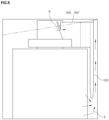
- FIG. 8 illustrates an example of generating a height difference by kinetic energy applied from one direction
- FIG. 9 is a plan view illustrating a mixing process of the lower specific gravity electrolyte B and the higher specific gravity electrolyte A
- FIG. 10 illustrates a flowing path of the higher specific gravity electrolyte A.
- a height difference may be generated in the electrolyte in a battery of the vehicle by kinetic energy applied from one direction due to inertia.
- the lower specific gravity electrolyte B disposed at the upper portion is introduced into the first mixing container 200 and the second mixing container 200' through the inlet/outlet groove 240, and the higher specific gravity electrolyte A disposed at the bottom portion is introduced into the first mixing container 200 and the second mixing container 200' through the first guide passage 510 and/or the second guide passage 520 due to inertia.
- the lower specific gravity electrolyte B flows to the first circulation path 251 and the second circulation path 252 after being introduced into the mixing container 200 through the inlet/outlet groove 240.
- the higher specific gravity electrolyte A flows into the first circulation path 251 and the second circulation path 252 after being introduced into the third circulation path 253 through the first guide passage 510.
- the flow direction of the higher specific gravity electrolyte A is changed due to the narrow space between the end of the expansion wall 221c and the inclined wall 230, and the higher specific gravity electrolyte A is introduced into the first circulation path 251 and the second circulation path 252. Therefore, the flow velocity of the higher specific gravity electrolyte A is increased while flowing from the wide space to the narrow space.
- the mixed electrolyte C provided at the first circulation path 251 and the second circulation path 252 is discharged into the third circulation path 253 through the exits of the first circulation path 251 and the second circulation path 252 (between the convergence wall 221a and the partition wall 211) which are configured to be narrower than the entrance. Therefore, the flow velocity of the mixed electrolyte C is increased once more and mixed with the higher specific gravity electrolyte A once more.
- the higher specific gravity electrolyte A and the lower specific gravity electrolyte B are mixed together while circulating through the first to third circulation paths 251, 252, and 253 provided by the pair of the labyrinth walls 221 and 222.
- the higher and the lower specific gravity electrolyte A and B push the mixed electrolyte C which was mixed at the mixing container 200 during the process of removing the height difference as shown in FIG. 8 .
- the mixed electrolyte C is discharged to the outside of the mixing container 200 as the height of the electrolyte in the mixing apparatus 3 becomes lower, and when the electrolyte forms the horizontal surface, the mixing container 200 receives the mixed electrolyte C therein.
- the mixed electrolyte C in the mixing container 200 is discharged as a height difference is generated oppositely by the kinetic energy applied from an opposite direction, and during the process of removing the height difference, the lower specific gravity electrolyte B and the higher specific gravity electrolyte A are introduced into the mixing container 200. This will be described with reference to FIGS. 11 to 13 .
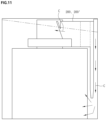
- FIG. 11 illustrates an example of generating the height difference by kinetic energy applied from the opposite direction
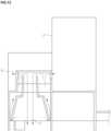
- FIG. 12 is a plan view illustrating a discharging process of the mixed electrolyte C
- FIG. 13 is a perspective view illustrating a discharging process of the mixed electrolyte C through the guide plate 100.
- the height of the electrolyte in the mixing apparatus 3 becomes lower due to kinetic energy, thereby causing a height difference.
- the remaining mixed electrolyte C in the first mixing container 200 and the second mixing container 200' is discharged to the outside of the mixing containers 200 and 200' by the kinetic energy. That is, the mixed electrolyte C is discharged into the upper portion of the battery through the inlet/outlet groove 240 while the surface height of the electrolyte gradually becomes lower, and is discharged downward into the bottom portion of the battery through the first guide passage 510 and/or the second guide passage 520.
- the inertia applied to the battery is removed, the height difference is removed, thereby the height of the electrolyte in the mixing apparatus 3 becomes higher and the height of the electrolyte in the opposite side becomes lower.
- the lower specific gravity electrolyte B and the higher specific gravity electrolyte A are efficiently mixed together through the processes of introduction and circulation thereof.
- the electrolyte mixing apparatus 3 for the battery capable of increasing the flow velocity of the electrolyte efficiently mixes the lower specific gravity electrolyte B and the higher specific gravity electrolyte A according to the acting direction of the kinetic energy, and discharges the mixed electrolyte C outside thereof when the kinetic energy is applied in an opposite direction. Further, a large amount of electrolyte can be efficiently mixed in a short period of time by controlling the space of the passage so as to increase the flow velocity of the electrolyte.
Landscapes
- Chemical & Material Sciences (AREA)
- Chemical Kinetics & Catalysis (AREA)
- Electrochemistry (AREA)
- General Chemical & Material Sciences (AREA)
- Engineering & Computer Science (AREA)
- Manufacturing & Machinery (AREA)
- Fuel Cell (AREA)
- Filling, Topping-Up Batteries (AREA)
Description
- The present invention generally relates to an electrolyte mixing apparatus for a battery capable of increasing a flow velocity of an electrolyte.
- A battery is a device generating an electromotive force by an internal chemical action. A battery is capable of being repeatedly charged and discharged, and therefore, it is generally called a secondary battery.
- As it is well known, in a battery, a positive electrode is composed of lead dioxide (PbO2), a negative electrode is composed of spongy lead (Pb), and an electrolyte is a diluted sulfuric acid (H2SO4).
- Such a battery makes current flow using a potential difference between the positive electrode and the negative electrode, each one consisting of the lead dioxide and the lead respectively, whereby power is generated for operating a load. Here, a casing of the battery is filled with the electrolyte and a surface of the filled electrolyte is higher than upper ends of pole plates fixed in the casing of the battery.
- As a certain time passes after the electrolyte has been supplied into the casing, during repeated uses of charging and discharging of battery, electrolyte stratification occurs wherein the electrolyte becomes layered according to specific gravity so that lower specific gravity electrolyte is disposed at an upper layer while higher specific gravity electrolyte sinks and is disposed at a bottom layer.
- Such conventional electrolyte stratification means a separation of the electrolyte into multiple layers according to specific gravities thereof. This is a general phenomenon caused by a difference in specific gravities under no convection state.
- However, a pole plate group restricts a flow of the electrolyte so that upper and lower portions of the electrolyte cannot be mixed smoothly with each other, thereby the electrolyte stratification occurs. That is, in the conventional battery, the electrolyte stratification makes the lower specific gravity electrolyte be disposed at the upper portion of the pole plate assembly, thereby corrosion of the upper portion of the pole plates is accelerated since the sulfuric acid solution of the lower specific gravity electrolyte has a relatively low concentration.
- Furthermore, in the conventional battery, since the higher specific gravity electrolyte is disposed at the lower portion of the battery where the pole plate assembly is provided, a terminal voltage of the battery may be indicated higher than an actual degree of charge. Such overvoltage may cause insufficient charge in a typical charging method of vehicles or other machines in which charge voltage is adjusted to a predetermined voltage. Moreover, continuous use of the battery in the insufficient charging state also accelerates sulfation of the pole plates, thus reducing the lifetime of the battery.
- An apparatus for mixing higher specific gravity electrolyte and lower specific gravity electrolyte according to a flow of an electrolyte in a battery is provided in the related art. However, in a case of heavy vehicles (for example, heavy buses or heavy trucks), such a conventional apparatus for mixing an electrolyte in a battery has large amount of the electrolyte therein, thus the electrolyte should be mixed in a short period of time.
- However, the conventional apparatus for mixing an electrolyte in a battery has a problem with time of mixing the higher specific gravity electrolyte and the lower specific gravity electrolyte, for example, in case of the conventional apparatus is applied to such a large capacity battery, since a flow of an electrolyte up and down takes a long time.
-
- (Patent Document 1)
Korean Patent Application Publication No. 10-2013-0122063 (2013.11.07 - (Patent Document 2)
Korean Patent Application Publication No. 10-2017-0051036 (2017.05.11 - (Patent Document 3)
U. S Patent No. 5,032,476 (1991.07.16 ). - Furthermore,
EP 2 660 894 A1 - Accordingly, the present invention has been made keeping in mind the above problems occurring in the related art, and the present invention is intended to provide an electrolyte mixing
apparatus for a battery capable of increasing a flow velocity of an electrolyte which is configured to increase a flow velocity of an electrolyte separated into higher specific gravity electrolyte and lower specific gravity electrolyte so as to mix the higher specific gravity electrolyte and the lower specific gravity electrolyte in a short period of time. - In addition, the present invention is intended to provide an electrolyte mixing apparatus for a battery capable of increasing a flow velocity of an electrolyte which is configured to efficiently mix higher specific gravity electrolyte and lower specific gravity electrolyte in a large capacity battery applied to heavy vehicles (buses or trucks).
- In order to achieve the above objects, the present invention provides the electrolyte mixing apparatus for a battery of
claim 1, as well as exemplary embodiments described hereinbelow. - According to an exemplary embodiment of the present invention, there is provided an electrolyte mixing apparatus for a battery capable of increasing a flow velocity of an electrolyte, the apparatus including,: a guide plate provided between an inner wall surface of a battery casing and a pole plate assembly so as to provide a passage to deliver the higher specific gravity electrolyte upwards by inertia, and to deliver downwards a mixed electrolyte provided at an upper portion; and at least one mixing container mixing the higher specific gravity electrolyte, introduced through the passage provided on the guide plate, with the lower specific gravity electrolyte introduced into the upper portion, and discharging the mixed electrolyte, according to a direction of inertia, wherein the mixing container includes: a receiving portion providing a space in a top portion of the guide plate for mixing the lower specific gravity electrolyte with the higher specific gravity electrolyte, and providing an inlet/outlet groove for introducing the lower specific gravity electrolyte and discharging the mixed electrolyte according to a direction of inertia; and a labyrinth portion having at least one circulation path, wherein an outlet of the circulation path is narrower than an
apparatus for a battery capable of increasing a flow velocity of an electrolyte which is configured to increase a flow velocity of an electrolyte separated into higher specific gravity electrolyte and lower specific gravity electrolyte so as to mix the higher specific gravity electrolyte and the lower specific gravity electrolyte in a short period of time. - In addition, the present invention is intended to provide an electrolyte mixing apparatus for a battery capable of increasing a flow velocity of an electrolyte which is configured to efficiently mix higher specific gravity electrolyte and lower specific gravity electrolyte in a large capacity battery applied to heavy vehicles (buses or trucks).
- In order to achieve the above objects, the present invention provides exemplary embodiments described hereinbelow.
- According to an exemplary embodiment of the present invention, there is provided an electrolyte mixing apparatus for a battery capable of increasing a flow velocity of an electrolyte, the apparatus including,: a guide plate provided between an inner wall surface of a battery casing and a pole plate assembly so as to provide a passage to deliver the higher specific gravity electrolyte upwards by inertia, and to deliver downwards a mixed electrolyte provided at an upper portion; and at least one mixing container mixing the higher specific gravity electrolyte, introduced through the passage provided on the guide plate, with the lower specific gravity electrolyte introduced into the upper portion, and discharging the mixed electrolyte, according to a direction of inertia, wherein the mixing container includes: a receiving portion providing a space in a top portion of the guide plate for mixing the lower specific gravity electrolyte with the higher specific gravity electrolyte, and providing an inlet/outlet groove for introducing the lower specific gravity electrolyte and discharging the mixed electrolyte according to a direction of inertia; and a labyrinth portion having at least one circulation path, wherein an outlet of the circulation path is narrower than an inlet so as to increase the flow velocity of the electrolyte, and the labyrinth portion mixing the lower specific gravity electrolyte, introduced through the inlet/outlet groove, with the higher specific gravity electrolyte, introduced through the guide plate.
- The electrolyte mixing apparatus for a battery according to the present invention can increase the flow velocity of both the lower specific gravity electrolyte and the higher specific gravity electrolyte, introduced into the mixing apparatus by inertia, thereby efficiently mixing the electrolyte in a short period of time.
- In addition, since the present invention is capable of increasing a flow velocity of the electrolyte, it is suitable for a large capacity battery.
- The above and other objects, features and other advantages of the present invention will be more clearly understood from the following detailed description when taken in conjunction with the accompanying drawings, in which:
-
FIGS. 1A and 1B are schematic diagrams describing a summary of an electrolyte mixing apparatus for a battery capable of increasing a flow velocity of an electrolyte according to the present invention; -
FIG. 2 is a front perspective view illustrating an electrolyte mixing apparatus for a battery capable of increasing a flow velocity of an electrolyte according to the present invention; -
FIG. 3 is a rear perspective view ofFIG. 2 ; -
FIG. 4 is a rear view ofFIG. 2 ; -
FIG. 5 is a side view ofFIG. 2 ; -
FIG. 6 is a plan view ofFig. 2 ; -
FIG. 7 illustrates a circulating path. -
FIG. 8 illustrates an example where a height difference is generated by kinetic energy applied from one direction; -
FIG. 9 is a plan view illustrating a mixing process of lower specific gravity electrolyte and higher specific gravity electrolyte; -
FIG. 10 illustrates a flowing path of higher specific gravity electrolyte; -
FIG. 11 illustrates an example where a height difference is generated by kinetic energy applied from an opposite direction; -
FIG. 12 is a plan view illustrating a discharging process of a mixed electrolyte; and -
FIG. 13 is a perspective view illustrating a discharging process of a mixed electrolyte through a guide plate. -
1: pole plate assembly 2: strap 3: mixing apparatus 4: casing A: higher specific gravity electrolyte B: lower specific gravity electrolyte C: mixed electrolyte 100: guide plate 110: incision portion 200, 200': mixing container 210: receiving portion 211: partition wall 21 1a: outer partition wall 211b: inner partition wall 212: extension wall 213: bottom surface 220: labyrinth portion 221, 222: labyrinth wall 221a, 222a: convergence wall 221b, 222b: conversion wall 221c, 222c: expansion wall 223: circulation port 230: inclined wall 240: inlet/outlet groove 251: first circulation path 252: second circulation path 253: third circulation path 300: connecting container 310, 320, 330: connecting portion 341, 342: sidewall 351, 352, 353: front wall 400: guide bar 510: first guide passage 520: second guide passage - Hereinbelow, to aid to understanding the invention, preferred embodiments of the present invention will be described in detail with reference to the accompanying drawings for allowing those skilled in the art to more clearly comprehend the present invention.
- All terms or words used herein should not be interpreted as being limited merely to common and dictionary meanings but should be interpreted as having meanings and concepts which are defined within the technical scope of the present invention.
- Unless the context clearly indicates otherwise, it will be further understood that the terms "comprises", "comprising", "includes", and/or "including", when used herein, specify the presence of stated features, integers, steps, operations, elements, and/or components, but do not preclude
the presence or addition of one or more other features, integers, steps, operations, elements, components, and/or groups thereof. - Hereinbelow, exemplary embodiments of the present invention will be described in detail with reference to the accompanying drawings.
-
FIGS. 1A and 1B are schematic diagrams describing a summary of an electrolyte mixing apparatus for a battery capable of increasing a flow velocity of an electrolyte according to the present invention. - Referring to
FIGS. 1A and 1B , anelectrolyte mixing apparatus 3 mixes and discharges an electrolyte by inertia, which is generated according to an operation of vehicles (for example, acceleration, steady speed, deceleration, stopped). - Here, the battery may consist of a
casing 4, apole plate assembly 1, and astrap 2. - The
casing 4 provides a place for containing an electrolyte, thepole plate assembly 1, and thestrap 2 therein. The electrolyte is dispersed into higher specific gravity electrolyte A and lower specific gravity electrolyte B, and each is disposed at a bottom portion and at an upper portion respectively. - The
pole plate assembly 1 consists of multiple positive and negative plates densely arranged alternately, and thestrap 2 connects the positive and negative pole plates to each other such that an electric current can flow therebetween. - Here, the
casing 4, thepole plate assembly 1, and thestrap 2 are generally applied by using known configurations, and thus will not be described here. - The
electrolyte mixing apparatus 3 according to the present invention is provided between thepole plate assembly 1 and an inner wall surface of thebattery casing 4, and mixes and discharges the electrolyte moved by the inertia. For example, referring toFIG. 1A , when the inertia is applied to the electrolyte in one direction, the lower specific gravity electrolyte B disposed at an upper portion of thecasing 4 is introduced into an upper portion of theelectrolyte mixing apparatus 3, and the higher specific gravity electrolyte A disposed at a bottom portion of thecasing 4 is introduced into the upper portion of theelectrolyte mixing apparatus 3 through a passage provided between the inner wall surface of thecasing 4. - At this point, in the inside of the
battery casing 4, the electrolyte is introduced into theelectrolyte mixing apparatus 3 due to kinetic energy generated by such inertia, so a height difference is generated. Thus, theelectrolyte mixing apparatus 3 mixes the higher specific gravity electrolyte A moved by the inertia with the lower specific gravity electrolyte B introduced from the upper portion, and then discharges the electrolyte so as to remove the height difference. - In addition, after the
electrolyte mixing apparatus 3 discharges mixed electrolyte C in such a process, the height difference is removed and the electrolyte becomes a horizontal surface so that theelectrolyte mixing apparatus 3 becomes a state of receiving the mixed electrolyte C therein. - After this, referring to
FIG. 1B , the electrolyte is moved to an opposite direction ofFIG. 1A by kinetic energy applied in an opposite direction, so a height difference is generated in an opposite side. At this time, the mixed electrolyte in theelectrolyte mixing apparatus 3 is quickly discharged to the upper side and the bottom side due to the height difference. - That is, the
electrolyte mixing apparatus 3 repeatedly mixes and discharges the higher and the lower specific gravity electrolytes A and B while the height difference of electrolyte by the inertia is generated and removed. - In addition, the present invention increases the flow velocity of the higher specific gravity electrolyte A moved from bottom portion of the
casing 4 so as to mix large amounts of higher specific gravity electrolyte A and lower specific gravity electrolyte B during such generation and removal processes of the height difference. -
FIG. 2 is a front perspective view,FIG. 3 is a rear perspective view,FIG. 4 is a rear view,FIG. 5 is a side view,FIG. 6 is a plan view illustrating an electrolyte mixing apparatus for a battery capable of increasing a flow velocity of an electrolyte according to the present invention, andFIG. 7 illustrates a circulating path. - Referring to
FIGS. 2 to 7 , anelectrolyte mixing apparatus 3 for a battery capable of increasing a flow velocity of an electrolyte according to the present invention includes aguide plate 100 which is provided between an inner wall surface of abattery casing 4 so as to provide a passage, at least one mixingcontainer 200 mixing an electrolyte, a connectingcontainer 300 connecting and supporting between mixingcontainers 200, and aguide bar 400 increasing a flow velocity at theguide plate 100. - The
guide plate 100 that is an upright panel provides passages between it and the inner wall surface of thecasing 4. The passages include a passage that delivers the higher specific gravity electrolyte A disposed at the bottom portion upwards, and a passage that delivers a mixed electrolyte C mixed at the mixingcontainer 200 downwards. Here, the passage for delivering the higher specific gravity electrolyte A upwards and the passage for delivering the mixed electrolyte C downwards may be configured as one passage or may be configured separately. - Further, the
guide plate 100 may include anincision portion 110, which is cut in the middle bottom portion of theguide plate 100 so as to deliver the higher specific gravity electrolyte A from the middle portion of theguide plate 100 to the connectingcontainer 300. Theincision portion 110 is cut in the middle bottom portion of theguide plate 100 and provides a path for delivering the higher specific gravity electrolyte A disposed at the bottom portion. - In addition, the
incision portion 110 may be provided for removing a resistance caused by residues formed by a hot melt adhesive introduced to bond thepole plate assembly 1 of the battery, or removing a resistance by a protrusion on the wall surface of thecasing 4. - For example, the
incision portion 110 may provide a space for receiving a protrusion or residues when the protrusion on the wall surface of thecasing 4 and the residues by the hot melt adhesive exist. That is, when theguide plate 100 is inserted between the wall surface of thecasing 4 and thepole plate assembly 1 and the protrusion exists on the wall surface of thecasing 4, the protrusion may be received in the space provided by theincision portion 110 and the resistance by the protrusion on the wall surface of thecasing 4 can be removed. - The mixing
container 200 provides a passage to circulate the introduced higher specific gravity electrolyte A and lower specific gravity electrolyte B so as to mix the higher specific gravity electrolyte A and the lower specific gravity electrolyte B together at the upper portion of theguide plate 100. - More specifically, the mixing
container 200 is configured to form abent bottom surface 213 at a top portion of theguide plate 100, and includes a receivingportion 210 provided with a space between opposite wall surfaces, alabyrinth portion 220 circulating the electrolyte inside the receivingportion 210, aninclined wall 230 extending slantingly from a front surface of the receivingportion 210, and an inlet/outlet groove 240 of introducing the lower specific gravity electrolyte B disposed at an upper portion and discharging the mixed electrolyte C. - The receiving
portion 210 includes thebottom surface 213 bent from the top portion of theupright guide plate 100,opposite partition walls 211 separating spaces standing at opposite sides, anupward step 214 extending upward from thebottom surface 213, and anextension wall 212 extending from thepartition wall 211 and providing thelabyrinth portion 220 and circulation paths. - The
partition walls 211 are a pair of walls spaced apart from each other, and define a space for providing thelabyrinth portion 220 therein. At this point, ends of thepartition walls 211 protrude towards the wall surface of thecasing 4 so as to provide a passage between thepartition walls 211. - That is, the higher specific gravity electrolyte A disposed at the bottom portion flows to the receiving
portion 210 providing thelabyrinth portion 220 therein through the passage defined between thepartition walls 211. - The
upward step 214 extends upward from thebottom surface 213 and supports thelabyrinth portion 220. Here, since theupward step 214 is placed above thebottom surface 213, theupward step 214 has a configuration that can be close to thestrap 2 at a top portion of thepole plate assembly 1. - For example, as shown at
FIGS. 1A and 1B , thestrap 2 connects multiple positive and negative pole plates such that an electric current can flow therebetween. - Accordingly, in the present invention, the
upward step 214 is configured to have a structure corresponding to shapes of thestrap 2 and thepole plate assembly 1, thereby enabling easy installing of thepole plate assembly 1 to which thestrap 2 is connected. Such a structure of theupward step 214 realizes an easy installation of themixing apparatus 3 in thecasing 4. - The
extension wall 212 extends to be bent from anouter partition wall 211a disposed at an outer side among the pair of thepartition walls 211. Here, theextension wall 212 is upright and spaced apart from thelabyrinth portion 220 so as to provide a passage for allowing a flow of the electrolyte between theextension wall 212 and thelabyrinth portion 220. Also, theextension wall 212 is configured to form an outer wall of theupward step 214. - The
inclined wall 230 slantingly extends upward from the end of theupward step 214, wherein theupward step 214 is surrounded by theextension wall 212 and aninner partition wall 211b, and extends upward from thebottom surface 213 of the receivingportion 210. At this point, theinclined wall 230 slantingly extends upward and is spaced apart from the ends of theextension wall 212 and theinner partition wall 211b so as to provide the inlet/outlet groove 240. - The inlet/
outlet groove 240 is a groove spaced apart from the ends of theinclined wall 230, theextension wall 212, and theinner partition wall 211b. The lower specific gravity electrolyte B disposed at the upper portion of thecasing 4 is introduced and the mixed electrolyte C is discharged, through the inlet/outlet groove 240. - Referring to
FIGS. 6 and7 , thelabyrinth portion 220 includesopposite labyrinth walls portion 210, and a circulation port 223 providing an inlet/outlet between the pair oflabyrinth walls - The pair of the
labyrinth walls first labyrinth wall 221 extending while being spaced apart from theouter partition wall 211a and theextension wall 212, and asecond labyrinth wall 222 extending while being spaced apart from theinner partition wall 211b. - The
first labyrinth wall 221 defines afirst circulation path 251, thesecond labyrinth wall 222 defines asecond circulation path 252, and athird circulation path 253 is defined between thefirst labyrinth wall 221 and thesecond labyrinth wall 222. - The circulation of electrolyte in the
first circulation path 251 to thethird circulation path 253 is different according to a direction of inertia. That is, when the inertia is applied to the direction in which the electrolyte is introduced, thefirst circulation path 251 and thesecond circulation path 252 circulate the lower specific gravity electrolyte B introduced through the inlet/outlet groove 240 and discharge the lower specific gravity electrolyte B into thethird circulation path 253, and thethird circulation path 253 circulates the higher specific gravity electrolyte A introduced through theguide plate 100 and discharges the higher specific gravity electrolyte A into thefirst circulation path 251 and thesecond circulation path 252. That is, thefirst circulation path 251 and thesecond circulation path 252 mix the lower specific gravity electrolyte B and the higher specific gravity electrolyte A together, and then discharge the mixed electrolyte into thethird circulation path 253. Thus, in thethird circulation path 253, the mixed electrolyte and the higher specific gravity electrolyte A are mixed together. - The mixed electrolyte C as described above is discharged when the inertia is applied to the opposite direction or when the height difference generated by the inertia is removed.
- Additionally, in an opposite case, the mixed electrolyte C which is a result of mixing the lower specific gravity electrolyte B and the higher specific gravity electrolyte A circulates to be discharged outside the mixing
container 200. For example, thefirst circulation path 251 and thesecond circulation path 252 guide the mixed electrolyte C to the inlet/outlet groove 240, and thethird circulation path 253 guides the mixed electrolyte C to theguide plate 100. - In the embodiment, the
first labyrinth wall 221 and thesecond labyrinth wall 222 have the same structure, so thefirst labyrinth wall 221 will be described as an example. - The
first labyrinth wall 221 includes aconvergence wall 221a spaced apart from theouter partition wall 211a, aconversion wall 221b bent from theconvergence wall 221a, and aexpansion wall 221c bent from theconversion wall 221b. - The
convergence wall 221a is upright at thebottom surface 213 and slantingly extends. Theconvergence wall 221a slantingly extends such that a gap between theconvergence wall 221a and theouter partition wall 211a becomes narrower in a direction toward the guide plate 100 (an exit side), thereby forming an exit of the first circulation path 251 (or the second circulation path 252). - The
conversion wall 221b is bent from the end of theconvergence wall 221a. At this point, theconversion wall 221b is formed in a similar structure with a structure of theextension wall 212 connected to thepartition wall 211. Such structure is to form thefirst circulation path 251 capable of switching the flow direction of the electrolyte introduced through theconvergence wall 221a or theexpansion wall 221c. - The
expansion wall 221c extends and is bent from theconversion wall 221b in the same direction as that of theextension wall 212, and forms the first circulation path 251 (or the second circulation path 252). Here, theexpansion wall 221c has a gap wider than gaps between theconvergence wall 221a and thepartition wall 211, and between theconversion wall 221b and thepartition wall 211. In addition, the end of theexpansion wall 221c is spaced apart from theinclined wall 230, thereby increasing the flow velocity of the higher specific gravity electrolyte A introduced from thethird circulation path 253. Further, the end of theexpansion wall 221c spaced apart from theinclined wall 230 may be connected with the inlet/outlet groove 240. - Here, as described above, the
first circulation path 251 and thesecond circulation path 252 defined by thefirst labyrinth wall 221 and thesecond labyrinth wall 222 are capable of increasing the flow velocity of the electrolyte since the exit side (between theconvergence wall 221a and the partition wall 211) has the narrowest gap. - In addition, the
third circulation path 253 is capable of increasing the flow velocity of the higher specific gravity electrolyte A since an exit side, the circulation port 223, is configured to be narrower than an entrance side connecting theguide plate 100. Additionally, the flow velocities of the higher specific gravity electrolyte A and the mixed electrolyte C introduced from thethird circulation path 253 into thefirst circulation path 251, and from thethird circulation path 253 into thesecond circulation path 252 can be increased as passing the narrow gap between theexpansion wall 221c and theinclined wall 230. - Referring to
FIGS. 3 ,4 , and7 , theguide bar 400 extends in a longitudinal direction on a surface of theguide plate 100 between the ends of theopposite partition walls 211, and separates afirst guide passage 510 and asecond guide passage 520 from each other. For example, theguide bar 400 slantingly extends from the bottom of theguide plate 100 in a direction toward the connectingcontainer 300. - Therefore, the
first guide passage 510 becomes enlarged gradually from a starting point (the bottom of the guide plate 100) to an end point (the entrance of the third circulation path 253) reaching thebottom surface 213, while thesecond guide passage 520 becomes narrow gradually. Such a difference in the shape of the passages is to deliver the higher specific gravity electrolyte A disposed at the bottom portion of thecasing 4 to thefirst circulation path 251 and thesecond circulation path 252 through thethird circulation path 253. That is, thefirst guide passage 510 extending to thethird circulation path 253 is enlarged so as to deliver a large amount of the higher specific gravity electrolyte A introduced into the mixingcontainer 200 from the bottom portion of thecasing 4. - In addition, a top of the
second guide passage 520 is close to a starting point of thefirst circulation path 251, as a width of thesecond guide passage 520 becomes narrow, thus the flow velocity of the higher specific gravity electrolyte A flowing therein increases. The higher specific gravity electrolyte A having such higher velocity bumps into the mixed electrolyte C discharged from thefirst circulation path 251, thereby being guided to flow to thethird circulation path 253. - That is, the
second guide passage 520 increases the flow velocity of the higher specific gravity electrolyte A moved from the bottom portion of thecasing 4, thus guiding a flow direction of the mixed electrolyte C to thethird circulation path 253, wherein the mixed electrolyte C is the result of mixing the lower specific gravity electrolyte B discharged from thefirst circulation path 251 with the higher specific gravity electrolyte A together. - According to such a structure, the higher specific gravity electrolyte A disposed at the bottom portion of the
casing 4 flows to thethird circulation path 253 of the mixingcontainer 200 through thefirst guide passage 510 and thesecond guide passage 520, and the higher specific gravity electrolyte A is mixed with the lower specific gravity electrolyte B introduced from thefirst circulation path 251 and thesecond circulation path 252 through the inlet/outlet groove 240 and circulates together with the lower specific gravity electrolyte B. - Referring to
FIGS. 2 ,3 , and6 , the connectingcontainer 300 is configured to divide multiple spaces between opposite mixingcontainers 200 so as to receive the higher specific gravity electrolyte A introduced from the bottom portion of thecasing 4. - For example, the connecting
container 300 is divided into first to third connectingportions 310 to 330 as afirst side wall 341 and asecond side wall 342 are configured to be spaced apart from each other at a position between thefirst mixing container 200 and a second mixing container 200'. Here, the first to third connectingportions 310 to 330 are configured as a secondbottom surface 313 horizontally bent from theguide plate 100, and may be divided by a firstfront wall 351 forming a front surface as extending between theinner partition wall 211b and thefirst side wall 341, a secondfront wall 352 forming a front surface of asecond connection portion 320 as extending between thefirst side wall 341 and thesecond side wall 342, and a thirdfront wall 353 forming a front surface as extending between thesecond side wall 342 and aninner partition wall 211b' of the second mixing container 200'. - Here, the end portions of the
first side wall 341 and thesecond side wall 342 protrude toward the surface of theguide plate 100 and provide the passage delivering the higher specific gravity electrolyte A introduced from theincision portion 110. That is, thefirst side wall 341 and theinner partition wall 211b of thefirst mixing container 200 provide a passage therebetween, wherein the passage is connected to the first connectingportion 310. In addition, thefirst side wall 341 and thesecond side wall 342 are spaced apart from each other so as to provide a passage for delivering the higher specific gravity electrolyte A to the second connecting portion through theincision portion 110. - In the same manner, the
second side wall 342 and theinner partition wall 211b' of the second mixing container 200' are spaced apart from each other and provide a passage connecting theincision portion 110 to the third connectingportion 330. - In addition, the first
front wall 351 and the thirdfront wall 353 are formed on the same plane, while the secondfront wall 352 is placed at a position in back of the firstfront wall 351 and the thirdfront wall 353. That is, the secondfront wall 352 is located to form a groove between the firstfront wall 351 and the thirdfront wall 353. - Additionally, the first connecting
portion 310 and thefirst mixing container 200 are configured in a stepped structure, and the third connectingportion 330 and the second mixing container 200' are configured in a stepped structure. - The stepped structure and groove are configured as considering an arrangement of the
strap 2 connected to an upper surface of thepole plate assembly 1. For example, thestrap 2 is configured in an L-shape, and a bus bar or other electric current flowing devices are connected to thestrap 2 so as to be connected to positive and negative terminal posts provided on the upper surface of thecasing 4. Therefore, when a pair ofstraps 2 is assembled on the pole plates to face each other while being spaced apart from each other, the first connectingportion 310 may be installed to be connected to afirst strap 2, and the third connectingportion 330 may be installed to be connected to asecond strap 2. - In addition, as stated above, the
incision portion 110 performs a role as the path for delivering the higher specific gravity electrolyte A, and also may be configured to realize a purpose for removing resistance caused by residues of the hot melt adhesive, in case of the hot melt adhesive which is introduced to bond thepole plate assembly 1 inside thecasing 4 remains on the wall surface of thecasing 4. - For example, the hot melt adhesive is generally injected at a predetermined location of the wall surface of the
casing 4 and is hardened at thebottom surface 213. Here, when the hot melt adhesive is injected through the wall surface of thecasing 4, there is a possibility that the hot melt is not fully introduced to thebottom surface 213, but may remain on the wall surface of thecasing 4. At this point, when theguide plate 100 is inserted into between thepole plate assembly 1 and the wall surface of thecasing 4, the residues of the hot melt adhesive on the wall surface of thecasing 4 may interfere with the insertion of theguide plate 100. - In the present invention, to overcome such a problem, the
incision portion 110 is formed with the consideration of the injecting location or point of the hot melt adhesive. That is, the present invention prevents the interference due to the residues of the hot melt adhesive as theincision portion 110 is formed considering the injecting location or point of the hot melt adhesive. - The present invention includes such structures as explained above, and hereinbelow, the operation of mixing the electrolyte achieved by such structures will be described with reference to
FIGS. 8 to 13 . -
FIG. 8 illustrates an example of generating a height difference by kinetic energy applied from one direction,FIG. 9 is a plan view illustrating a mixing process of the lower specific gravity electrolyte B and the higher specific gravity electrolyte A, andFIG. 10 illustrates a flowing path of the higher specific gravity electrolyte A. - For example, referring to
FIGS. 8 to 10 , when a vehicle is accelerated from a stopped or steady speed state, a height difference may be generated in the electrolyte in a battery of the vehicle by kinetic energy applied from one direction due to inertia. - Therefore, the lower specific gravity electrolyte B disposed at the upper portion is introduced into the
first mixing container 200 and the second mixing container 200' through the inlet/outlet groove 240, and the higher specific gravity electrolyte A disposed at the bottom portion is introduced into thefirst mixing container 200 and the second mixing container 200' through thefirst guide passage 510 and/or thesecond guide passage 520 due to inertia. - At this point, the lower specific gravity electrolyte B flows to the
first circulation path 251 and thesecond circulation path 252 after being introduced into the mixingcontainer 200 through the inlet/outlet groove 240. - In addition, the higher specific gravity electrolyte A flows into the
first circulation path 251 and thesecond circulation path 252 after being introduced into thethird circulation path 253 through thefirst guide passage 510. At this point, the flow direction of the higher specific gravity electrolyte A is changed due to the narrow space between the end of theexpansion wall 221c and theinclined wall 230, and the higher specific gravity electrolyte A is introduced into thefirst circulation path 251 and thesecond circulation path 252. Therefore, the flow velocity of the higher specific gravity electrolyte A is increased while flowing from the wide space to the narrow space. - Therefore, the lower specific gravity electrolyte B and the higher specific gravity electrolyte A are mixed at the
first circulation path 251 and thesecond circulation path 252. - In addition, the mixed electrolyte C provided at the
first circulation path 251 and thesecond circulation path 252 is discharged into thethird circulation path 253 through the exits of thefirst circulation path 251 and the second circulation path 252 (between theconvergence wall 221a and the partition wall 211) which are configured to be narrower than the entrance. Therefore, the flow velocity of the mixed electrolyte C is increased once more and mixed with the higher specific gravity electrolyte A once more. - That is, in the present invention, the higher specific gravity electrolyte A and the lower specific gravity electrolyte B are mixed together while circulating through the first to
third circulation paths labyrinth walls - Afterwards, when the kinetic energy applied from one direction by the inertia is removed, the higher and the lower specific gravity electrolyte A and B push the mixed electrolyte C which was mixed at the mixing
container 200 during the process of removing the height difference as shown inFIG. 8 . At this point, the mixed electrolyte C is discharged to the outside of the mixingcontainer 200 as the height of the electrolyte in themixing apparatus 3 becomes lower, and when the electrolyte forms the horizontal surface, the mixingcontainer 200 receives the mixed electrolyte C therein. - The mixed electrolyte C in the mixing
container 200 is discharged as a height difference is generated oppositely by the kinetic energy applied from an opposite direction, and during the process of removing the height difference, the lower specific gravity electrolyte B and the higher specific gravity electrolyte A are introduced into the mixingcontainer 200. This will be described with reference toFIGS. 11 to 13 . -
FIG. 11 illustrates an example of generating the height difference by kinetic energy applied from the opposite direction,FIG. 12 is a plan view illustrating a discharging process of the mixed electrolyte C, andFIG. 13 is a perspective view illustrating a discharging process of the mixed electrolyte C through theguide plate 100. - Referring to
FIGS. 11 to 13 , when the opposite directional inertia is applied to the higher and the lower specific gravity electrolyte A and B, the height of the electrolyte in themixing apparatus 3 becomes lower due to kinetic energy, thereby causing a height difference. At this point, the remaining mixed electrolyte C in thefirst mixing container 200 and the second mixing container 200' is discharged to the outside of the mixingcontainers 200 and 200' by the kinetic energy. That is, the mixed electrolyte C is discharged into the upper portion of the battery through the inlet/outlet groove 240 while the surface height of the electrolyte gradually becomes lower, and is discharged downward into the bottom portion of the battery through thefirst guide passage 510 and/or thesecond guide passage 520. - Afterwards, when the inertia applied to the battery is removed, the height difference is removed, thereby the height of the electrolyte in the
mixing apparatus 3 becomes higher and the height of the electrolyte in the opposite side becomes lower. In this process, the lower specific gravity electrolyte B and the higher specific gravity electrolyte A are efficiently mixed together through the processes of introduction and circulation thereof. - That is, the
electrolyte mixing apparatus 3 for the battery capable of increasing the flow velocity of the electrolyte efficiently mixes the lower specific gravity electrolyte B and the higher specific gravity electrolyte A according to the acting direction of the kinetic energy, and discharges the mixed electrolyte C outside thereof when the kinetic energy is applied in an opposite direction. Further, a large amount of electrolyte can be efficiently mixed in a short period of time by controlling the space of the passage so as to increase the flow velocity of the electrolyte. - It is thus well known to those skilled in that art that the present invention is not limited to the embodiment disclosed in the detailed description, and the patent right of the present invention should be defined by the scope and spirit of the invention as disclosed in the accompanying claims. Accordingly, it should be understood that the present invention includes various modifications, additions and substitutions without departing from the scope and spirit of the invention as disclosed in the accompanying claims.
Claims (7)
- An electrolyte mixing apparatus for a battery, the apparatus being configured to increase a flow velocity of an electrolyte and comprising:a guide plate (100) provided between an inner wall surface of a battery casing (4) and a pole plate assembly (1) so as to provide a passage to deliver higher specific gravity electrolyte (A) upwards by inertia, and to deliver downwards mixed electrolyte (C) provided at an upper portion thereof; andat least one mixing container (200) mixing the higher specific gravity electrolyte (A), introduced through the passage provided on the guide plate (100), with the lower specific gravity electrolyte (B), introduced into the upper portion, and discharging the mixed electrolyte (C), according to a direction of inertia,wherein the mixing container (200) comprises:a receiving portion (210) providing a space in a top portion of the guide plate (100) for mixing the lower specific gravity electrolyte (B) with the higher specific gravity electrolyte (A), and providing an inlet/outlet groove (240) for introducing the lower specific gravity electrolyte (B) and discharging the mixed electrolyte (C) according to a direction of inertia;wherein the mixing container (200) comprises:a labyrinth portion (220) having at least one circulation path, wherein an outlet of the circulation path is narrower than an inlet so as to increase the flow velocity of the electrolyte, and the labyrinth portion (220) mixing the lower specific gravity electrolyte (B), introduced through the inlet/outlet groove (240), with the higher specific gravity electrolyte (A), introduced through the guide plate (100),characterized in that the circulation path comprises:a first circulation path (251) provided between an outer partition wall (211a) of the receiving portion (210) and a first labyrinth wall (221) spaced apart therefrom;a second circulation path (252) provided between an inner partition wall (211b) of the receiving portion (210) and a second labyrinth wall (222) spaced apart therefrom; anda third circulation path (253) extending between the first labyrinth wall (221) and the second labyrinth wall (222) so as to be connected with the passage provided on the guide plate (100),whereininlets of the first circulation path (251) and the second circulation path (252) are connected with the inlet/outlet groove (240) and an outlet of the third circulation path (253), andoutlets thereof are connected with an inlet of the third circulation path (253),thereby mixing the lower specific gravity electrolyte (B) introduced through the inlet/outlet groove (240) with the higher specific gravity electrolyte (A) introduced through the third circulation path (253), and then discharging the mixed electrolyte (C) into the third circulation path (253).
- The electrolyte mixing apparatus of claim 1, wherein the labyrinth portion comprises:a convergence wall (221a) extending such that a gap between the convergence wall (221a) and the outer partition wall (211a) of the receiving portion (210) becomes narrower toward the guide plate (100);a conversion wall (221b) being bent from the convergence wall (221a); andan expansion wall (221c) being bent forward from the conversion wall (221b) and extending to form an end spaced apart from a front surface of the receiving portion (210).
- The electrolyte mixing apparatus of claim 1, wherein the passage of the guide plate (100) extends in a longitudinal direction at a location between opposite wall surfaces of the receiving portion (210), and is provided between ends protruding from one surface of the guide plate (100) toward the inner wall surface of the casing (4).
- The electrolyte mixing apparatus of claim 1, wherein the passage of the guide plate (100) is partitioned by a guide bar (400) extending in a longitudinal direction on a surface of the guide plate at a location between spaced ends protruding from opposite wall surfaces of the receiving portion (210).
- The electrolyte mixing apparatus of claim 4, wherein the passage of the guide plate (100) comprises:a first guide passage (510) provided on one side of the guide bar (400) slantingly extending, with a width of the first guide passage becoming enlarged as the first guide passage (510) goes upward; anda second guide passage (520) provided on the other side of the guide bar (400), with a width of the second guide passage becoming narrow as the second guide passage (520) goes upward.
- The electrolyte mixing apparatus of claim 1, further comprising: a connecting container (300) connected between opposite mixing containers (200) and provided with multiple connecting portions partitioned at the top portion of the guide plate (100).
- The electrolyte mixing apparatus of claim 1, the receiving portion (210) further comprising: an inclined wall (230) inclinedly extending upward from a front surface of the receiving portion (210) to be spaced apart from opposite wall surfaces of the receiving portion (210), and providing the inlet/outlet groove (240) between the inclined wall (230) and the opposite wall surfaces of the receiving portion (210).
Applications Claiming Priority (1)
| Application Number | Priority Date | Filing Date | Title |
|---|---|---|---|
| KR1020170106834A KR101916406B1 (en) | 2017-08-23 | 2017-08-23 | Electrolyte mixing apparatus for battery capable of increasing flow velocity of electrolyte |
Publications (2)
| Publication Number | Publication Date |
|---|---|
| EP3447825A1 EP3447825A1 (en) | 2019-02-27 |
| EP3447825B1 true EP3447825B1 (en) | 2023-06-14 |
Family
ID=60813640
Family Applications (1)
| Application Number | Title | Priority Date | Filing Date |
|---|---|---|---|
| EP17209927.7A Active EP3447825B1 (en) | 2017-08-23 | 2017-12-22 | Electrolyte mixing apparatus for battery capable of increasing flow velocity of electrolyte |
Country Status (3)
| Country | Link |
|---|---|
| EP (1) | EP3447825B1 (en) |
| KR (1) | KR101916406B1 (en) |
| ES (1) | ES2955104T3 (en) |
Citations (1)
| Publication number | Priority date | Publication date | Assignee | Title |
|---|---|---|---|---|
| EP0417186B1 (en) * | 1988-05-31 | 1996-01-17 | Globe-Union Inc. | Internal hydrostatic pump for a mobile vehicle battery |
Family Cites Families (5)
| Publication number | Priority date | Publication date | Assignee | Title |
|---|---|---|---|---|
| US5032476A (en) | 1990-07-19 | 1991-07-16 | Globe-Union, Inc. | Internal hydrostatic pump for a mobile vehicle battery |
| EP2628202B1 (en) * | 2010-10-15 | 2018-12-05 | Johnson Controls Autobatterie GmbH & Co. KGaA | Rechargeable battery having a wall element, and wall element therefor |
| DE102011111516A1 (en) * | 2011-08-31 | 2013-02-28 | Akkumulatorenfabrik Moll Gmbh & Co. Kg | Battery, battery box and method of manufacturing a battery |
| KR101338833B1 (en) * | 2012-04-30 | 2013-12-06 | 세방전지(주) | Mixing apparatus for battery electrolyte |
| KR20170051036A (en) | 2015-11-02 | 2017-05-11 | 주식회사 아트라스비엑스 | A lead-acid battery improved electrolyte circulation |
-
2017
- 2017-08-23 KR KR1020170106834A patent/KR101916406B1/en active Active
- 2017-12-22 ES ES17209927T patent/ES2955104T3/en active Active
- 2017-12-22 EP EP17209927.7A patent/EP3447825B1/en active Active
Patent Citations (1)
| Publication number | Priority date | Publication date | Assignee | Title |
|---|---|---|---|---|
| EP0417186B1 (en) * | 1988-05-31 | 1996-01-17 | Globe-Union Inc. | Internal hydrostatic pump for a mobile vehicle battery |
Also Published As
| Publication number | Publication date |
|---|---|
| KR101916406B1 (en) | 2018-11-08 |
| ES2955104T3 (en) | 2023-11-28 |
| EP3447825A1 (en) | 2019-02-27 |
Similar Documents
| Publication | Publication Date | Title |
|---|---|---|
| CN100454657C (en) | Battery module with improved cooling efficiency | |
| KR101338833B1 (en) | Mixing apparatus for battery electrolyte | |
| JP7034560B2 (en) | Power supply | |
| US20120214032A1 (en) | Secondary battery with improved destratification | |
| US20180248239A1 (en) | Air cooling battery module having guide vane | |
| KR101418891B1 (en) | Method for producing a liquid electrolyte battery | |
| DE112005001860T5 (en) | Mounting construction of electrical equipment | |
| CN101682003A (en) | Middle-or large-sized battery pack case providing improved coolant flux distribution uniformity | |
| CN101743651A (en) | Battery with electrolyte mixing device | |
| US20200373532A1 (en) | Module housing, battery module, high voltage battery, motor vehicle and method for introducing a heat transfer medium between a battery module and a cooling bottom | |
| ES2367186T3 (en) | PROCEDURE AND PROVISION FOR THE MODIFICATION OF THE STATUS OF CHARGING AND THE STATUS OF UTILITY (SOC; SOH) OF A BATTERY. | |
| KR20070088994A (en) | Medium and large battery packs with excellent cooling efficiency | |
| KR20190012461A (en) | Battery rack and energy storage system comprising the same | |
| EP3447825A1 (en) | Electrolyte mixing apparatus for battery capable of increasing flow velocity of electrolyte | |
| EP4648198A1 (en) | Battery pack | |
| DE112011105562B4 (en) | vehicle | |
| RU2611585C2 (en) | Battery with electrolyte mixing device | |
| AU774019B2 (en) | The improved combining structure between the battery electrode plates and the battery case | |
| CN216580405U (en) | Automobile all-in-one high-voltage distribution box | |
| EP3161894B1 (en) | Manufacturing process for gel batteries and apparatus therefor | |
| KR20250050469A (en) | Suppoter gripper and secondary battery including the same | |
| KR20180045448A (en) | A lead-acid battery improve electrolyte circulation | |
| KR20060101670A (en) | Secondary battery module | |
| KR102388651B1 (en) | Electrolytic cell | |
| JP7725224B2 (en) | Electrode group and lead-acid battery |
Legal Events
| Date | Code | Title | Description |
|---|---|---|---|
| PUAI | Public reference made under article 153(3) epc to a published international application that has entered the european phase |
Free format text: ORIGINAL CODE: 0009012 |
|
| STAA | Information on the status of an ep patent application or granted ep patent |
Free format text: STATUS: REQUEST FOR EXAMINATION WAS MADE |
|
| 17P | Request for examination filed |
Effective date: 20171222 |
|
| AK | Designated contracting states |
Kind code of ref document: A1 Designated state(s): AL AT BE BG CH CY CZ DE DK EE ES FI FR GB GR HR HU IE IS IT LI LT LU LV MC MK MT NL NO PL PT RO RS SE SI SK SM TR |
|
| AX | Request for extension of the european patent |
Extension state: BA ME |
|
| STAA | Information on the status of an ep patent application or granted ep patent |
Free format text: STATUS: EXAMINATION IS IN PROGRESS |
|
| 17Q | First examination report despatched |
Effective date: 20210208 |
|
| REG | Reference to a national code |
Ref country code: DE Ref legal event code: R079 Ref document number: 602017070160 Country of ref document: DE Free format text: PREVIOUS MAIN CLASS: H01M0002380000 Ipc: H01M0050700000 |
|
| GRAP | Despatch of communication of intention to grant a patent |
Free format text: ORIGINAL CODE: EPIDOSNIGR1 |
|
| STAA | Information on the status of an ep patent application or granted ep patent |
Free format text: STATUS: GRANT OF PATENT IS INTENDED |
|
| RIC1 | Information provided on ipc code assigned before grant |
Ipc: H01M 10/42 20060101ALI20221209BHEP Ipc: H01M 10/12 20060101ALI20221209BHEP Ipc: H01M 50/70 20210101AFI20221209BHEP |
|
| INTG | Intention to grant announced |
Effective date: 20230111 |
|
| GRAS | Grant fee paid |
Free format text: ORIGINAL CODE: EPIDOSNIGR3 |
|
| GRAA | (expected) grant |
Free format text: ORIGINAL CODE: 0009210 |
|
| STAA | Information on the status of an ep patent application or granted ep patent |
Free format text: STATUS: THE PATENT HAS BEEN GRANTED |
|
| AK | Designated contracting states |
Kind code of ref document: B1 Designated state(s): AL AT BE BG CH CY CZ DE DK EE ES FI FR GB GR HR HU IE IS IT LI LT LU LV MC MK MT NL NO PL PT RO RS SE SI SK SM TR |
|
| REG | Reference to a national code |
Ref country code: CH Ref legal event code: EP |
|
| REG | Reference to a national code |
Ref country code: DE Ref legal event code: R096 Ref document number: 602017070160 Country of ref document: DE |
|
| REG | Reference to a national code |
Ref country code: AT Ref legal event code: REF Ref document number: 1579909 Country of ref document: AT Kind code of ref document: T Effective date: 20230715 |
|
| REG | Reference to a national code |
Ref country code: LT Ref legal event code: MG9D |
|
| REG | Reference to a national code |
Ref country code: NL Ref legal event code: MP Effective date: 20230614 |
|
| PG25 | Lapsed in a contracting state [announced via postgrant information from national office to epo] |
Ref country code: SE Free format text: LAPSE BECAUSE OF FAILURE TO SUBMIT A TRANSLATION OF THE DESCRIPTION OR TO PAY THE FEE WITHIN THE PRESCRIBED TIME-LIMIT Effective date: 20230614 Ref country code: NO Free format text: LAPSE BECAUSE OF FAILURE TO SUBMIT A TRANSLATION OF THE DESCRIPTION OR TO PAY THE FEE WITHIN THE PRESCRIBED TIME-LIMIT Effective date: 20230914 |
|
| REG | Reference to a national code |
Ref country code: ES Ref legal event code: FG2A Ref document number: 2955104 Country of ref document: ES Kind code of ref document: T3 Effective date: 20231128 |
|
| PG25 | Lapsed in a contracting state [announced via postgrant information from national office to epo] |
Ref country code: RS Free format text: LAPSE BECAUSE OF FAILURE TO SUBMIT A TRANSLATION OF THE DESCRIPTION OR TO PAY THE FEE WITHIN THE PRESCRIBED TIME-LIMIT Effective date: 20230614 Ref country code: NL Free format text: LAPSE BECAUSE OF FAILURE TO SUBMIT A TRANSLATION OF THE DESCRIPTION OR TO PAY THE FEE WITHIN THE PRESCRIBED TIME-LIMIT Effective date: 20230614 Ref country code: LV Free format text: LAPSE BECAUSE OF FAILURE TO SUBMIT A TRANSLATION OF THE DESCRIPTION OR TO PAY THE FEE WITHIN THE PRESCRIBED TIME-LIMIT Effective date: 20230614 Ref country code: LT Free format text: LAPSE BECAUSE OF FAILURE TO SUBMIT A TRANSLATION OF THE DESCRIPTION OR TO PAY THE FEE WITHIN THE PRESCRIBED TIME-LIMIT Effective date: 20230614 Ref country code: HR Free format text: LAPSE BECAUSE OF FAILURE TO SUBMIT A TRANSLATION OF THE DESCRIPTION OR TO PAY THE FEE WITHIN THE PRESCRIBED TIME-LIMIT Effective date: 20230614 Ref country code: GR Free format text: LAPSE BECAUSE OF FAILURE TO SUBMIT A TRANSLATION OF THE DESCRIPTION OR TO PAY THE FEE WITHIN THE PRESCRIBED TIME-LIMIT Effective date: 20230915 |
|
| PG25 | Lapsed in a contracting state [announced via postgrant information from national office to epo] |
Ref country code: FI Free format text: LAPSE BECAUSE OF FAILURE TO SUBMIT A TRANSLATION OF THE DESCRIPTION OR TO PAY THE FEE WITHIN THE PRESCRIBED TIME-LIMIT Effective date: 20230614 |
|
| PG25 | Lapsed in a contracting state [announced via postgrant information from national office to epo] |
Ref country code: SK Free format text: LAPSE BECAUSE OF FAILURE TO SUBMIT A TRANSLATION OF THE DESCRIPTION OR TO PAY THE FEE WITHIN THE PRESCRIBED TIME-LIMIT Effective date: 20230614 |
|
| PG25 | Lapsed in a contracting state [announced via postgrant information from national office to epo] |
Ref country code: IS Free format text: LAPSE BECAUSE OF FAILURE TO SUBMIT A TRANSLATION OF THE DESCRIPTION OR TO PAY THE FEE WITHIN THE PRESCRIBED TIME-LIMIT Effective date: 20231014 |
|
| PG25 | Lapsed in a contracting state [announced via postgrant information from national office to epo] |
Ref country code: SM Free format text: LAPSE BECAUSE OF FAILURE TO SUBMIT A TRANSLATION OF THE DESCRIPTION OR TO PAY THE FEE WITHIN THE PRESCRIBED TIME-LIMIT Effective date: 20230614 Ref country code: SK Free format text: LAPSE BECAUSE OF FAILURE TO SUBMIT A TRANSLATION OF THE DESCRIPTION OR TO PAY THE FEE WITHIN THE PRESCRIBED TIME-LIMIT Effective date: 20230614 Ref country code: RO Free format text: LAPSE BECAUSE OF FAILURE TO SUBMIT A TRANSLATION OF THE DESCRIPTION OR TO PAY THE FEE WITHIN THE PRESCRIBED TIME-LIMIT Effective date: 20230614 Ref country code: PT Free format text: LAPSE BECAUSE OF FAILURE TO SUBMIT A TRANSLATION OF THE DESCRIPTION OR TO PAY THE FEE WITHIN THE PRESCRIBED TIME-LIMIT Effective date: 20231016 Ref country code: IS Free format text: LAPSE BECAUSE OF FAILURE TO SUBMIT A TRANSLATION OF THE DESCRIPTION OR TO PAY THE FEE WITHIN THE PRESCRIBED TIME-LIMIT Effective date: 20231014 Ref country code: EE Free format text: LAPSE BECAUSE OF FAILURE TO SUBMIT A TRANSLATION OF THE DESCRIPTION OR TO PAY THE FEE WITHIN THE PRESCRIBED TIME-LIMIT Effective date: 20230614 Ref country code: CZ Free format text: LAPSE BECAUSE OF FAILURE TO SUBMIT A TRANSLATION OF THE DESCRIPTION OR TO PAY THE FEE WITHIN THE PRESCRIBED TIME-LIMIT Effective date: 20230614 |
|
| PG25 | Lapsed in a contracting state [announced via postgrant information from national office to epo] |
Ref country code: PL Free format text: LAPSE BECAUSE OF FAILURE TO SUBMIT A TRANSLATION OF THE DESCRIPTION OR TO PAY THE FEE WITHIN THE PRESCRIBED TIME-LIMIT Effective date: 20230614 |
|
| REG | Reference to a national code |
Ref country code: DE Ref legal event code: R097 Ref document number: 602017070160 Country of ref document: DE |
|
| PLBE | No opposition filed within time limit |
Free format text: ORIGINAL CODE: 0009261 |
|
| STAA | Information on the status of an ep patent application or granted ep patent |
Free format text: STATUS: NO OPPOSITION FILED WITHIN TIME LIMIT |
|
| PG25 | Lapsed in a contracting state [announced via postgrant information from national office to epo] |
Ref country code: DK Free format text: LAPSE BECAUSE OF FAILURE TO SUBMIT A TRANSLATION OF THE DESCRIPTION OR TO PAY THE FEE WITHIN THE PRESCRIBED TIME-LIMIT Effective date: 20230614 |
|
| PG25 | Lapsed in a contracting state [announced via postgrant information from national office to epo] |
Ref country code: SI Free format text: LAPSE BECAUSE OF FAILURE TO SUBMIT A TRANSLATION OF THE DESCRIPTION OR TO PAY THE FEE WITHIN THE PRESCRIBED TIME-LIMIT Effective date: 20230614 |
|
| 26N | No opposition filed |
Effective date: 20240315 |
|
| PG25 | Lapsed in a contracting state [announced via postgrant information from national office to epo] |
Ref country code: SI Free format text: LAPSE BECAUSE OF FAILURE TO SUBMIT A TRANSLATION OF THE DESCRIPTION OR TO PAY THE FEE WITHIN THE PRESCRIBED TIME-LIMIT Effective date: 20230614 |
|
| REG | Reference to a national code |
Ref country code: CH Ref legal event code: PL |
|
| PG25 | Lapsed in a contracting state [announced via postgrant information from national office to epo] |
Ref country code: LU Free format text: LAPSE BECAUSE OF NON-PAYMENT OF DUE FEES Effective date: 20231222 |
|
| PG25 | Lapsed in a contracting state [announced via postgrant information from national office to epo] |
Ref country code: MC Free format text: LAPSE BECAUSE OF FAILURE TO SUBMIT A TRANSLATION OF THE DESCRIPTION OR TO PAY THE FEE WITHIN THE PRESCRIBED TIME-LIMIT Effective date: 20230614 |
|
| REG | Reference to a national code |
Ref country code: BE Ref legal event code: MM Effective date: 20231231 |
|
| PG25 | Lapsed in a contracting state [announced via postgrant information from national office to epo] |
Ref country code: MC Free format text: LAPSE BECAUSE OF FAILURE TO SUBMIT A TRANSLATION OF THE DESCRIPTION OR TO PAY THE FEE WITHIN THE PRESCRIBED TIME-LIMIT Effective date: 20230614 Ref country code: LU Free format text: LAPSE BECAUSE OF NON-PAYMENT OF DUE FEES Effective date: 20231222 |
|
| REG | Reference to a national code |
Ref country code: IE Ref legal event code: MM4A |
|
| PG25 | Lapsed in a contracting state [announced via postgrant information from national office to epo] |
Ref country code: IE Free format text: LAPSE BECAUSE OF NON-PAYMENT OF DUE FEES Effective date: 20231222 |
|
| PG25 | Lapsed in a contracting state [announced via postgrant information from national office to epo] |
Ref country code: BE Free format text: LAPSE BECAUSE OF NON-PAYMENT OF DUE FEES Effective date: 20231231 |
|
| PG25 | Lapsed in a contracting state [announced via postgrant information from national office to epo] |
Ref country code: FR Free format text: LAPSE BECAUSE OF NON-PAYMENT OF DUE FEES Effective date: 20231231 |
|
| PG25 | Lapsed in a contracting state [announced via postgrant information from national office to epo] |
Ref country code: CH Free format text: LAPSE BECAUSE OF NON-PAYMENT OF DUE FEES Effective date: 20231231 |
|
| PG25 | Lapsed in a contracting state [announced via postgrant information from national office to epo] |
Ref country code: IE Free format text: LAPSE BECAUSE OF NON-PAYMENT OF DUE FEES Effective date: 20231222 Ref country code: FR Free format text: LAPSE BECAUSE OF NON-PAYMENT OF DUE FEES Effective date: 20231231 Ref country code: CH Free format text: LAPSE BECAUSE OF NON-PAYMENT OF DUE FEES Effective date: 20231231 Ref country code: BE Free format text: LAPSE BECAUSE OF NON-PAYMENT OF DUE FEES Effective date: 20231231 |
|
| PG25 | Lapsed in a contracting state [announced via postgrant information from national office to epo] |
Ref country code: BG Free format text: LAPSE BECAUSE OF FAILURE TO SUBMIT A TRANSLATION OF THE DESCRIPTION OR TO PAY THE FEE WITHIN THE PRESCRIBED TIME-LIMIT Effective date: 20230614 |
|
| REG | Reference to a national code |
Ref country code: AT Ref legal event code: UEP Ref document number: 1579909 Country of ref document: AT Kind code of ref document: T Effective date: 20230614 |
|
| PG25 | Lapsed in a contracting state [announced via postgrant information from national office to epo] |
Ref country code: BG Free format text: LAPSE BECAUSE OF FAILURE TO SUBMIT A TRANSLATION OF THE DESCRIPTION OR TO PAY THE FEE WITHIN THE PRESCRIBED TIME-LIMIT Effective date: 20230614 |
|
| PG25 | Lapsed in a contracting state [announced via postgrant information from national office to epo] |
Ref country code: CY Free format text: LAPSE BECAUSE OF FAILURE TO SUBMIT A TRANSLATION OF THE DESCRIPTION OR TO PAY THE FEE WITHIN THE PRESCRIBED TIME-LIMIT; INVALID AB INITIO Effective date: 20171222 |
|
| PG25 | Lapsed in a contracting state [announced via postgrant information from national office to epo] |
Ref country code: HU Free format text: LAPSE BECAUSE OF FAILURE TO SUBMIT A TRANSLATION OF THE DESCRIPTION OR TO PAY THE FEE WITHIN THE PRESCRIBED TIME-LIMIT; INVALID AB INITIO Effective date: 20171222 |
|
| PG25 | Lapsed in a contracting state [announced via postgrant information from national office to epo] |
Ref country code: TR Free format text: LAPSE BECAUSE OF FAILURE TO SUBMIT A TRANSLATION OF THE DESCRIPTION OR TO PAY THE FEE WITHIN THE PRESCRIBED TIME-LIMIT Effective date: 20230614 |
|
| PGFP | Annual fee paid to national office [announced via postgrant information from national office to epo] |
Ref country code: GB Payment date: 20251218 Year of fee payment: 9 |
|
| PGFP | Annual fee paid to national office [announced via postgrant information from national office to epo] |
Ref country code: AT Payment date: 20251215 Year of fee payment: 9 |
|
| PGFP | Annual fee paid to national office [announced via postgrant information from national office to epo] |
Ref country code: ES Payment date: 20260119 Year of fee payment: 9 |
|
| PGFP | Annual fee paid to national office [announced via postgrant information from national office to epo] |
Ref country code: DE Payment date: 20260223 Year of fee payment: 9 |
|
| PGFP | Annual fee paid to national office [announced via postgrant information from national office to epo] |
Ref country code: IT Payment date: 20251231 Year of fee payment: 9 |